EP4227540B1 - Storable fan - Google Patents
Storable fan Download PDFInfo
- Publication number
- EP4227540B1 EP4227540B1 EP20959397.9A EP20959397A EP4227540B1 EP 4227540 B1 EP4227540 B1 EP 4227540B1 EP 20959397 A EP20959397 A EP 20959397A EP 4227540 B1 EP4227540 B1 EP 4227540B1
- Authority
- EP
- European Patent Office
- Prior art keywords
- rod
- fan
- base
- storable
- support rod
- Prior art date
- Legal status (The legal status is an assumption and is not a legal conclusion. Google has not performed a legal analysis and makes no representation as to the accuracy of the status listed.)
- Active
Links
Images










Classifications
-
- F—MECHANICAL ENGINEERING; LIGHTING; HEATING; WEAPONS; BLASTING
- F04—POSITIVE - DISPLACEMENT MACHINES FOR LIQUIDS; PUMPS FOR LIQUIDS OR ELASTIC FLUIDS
- F04D—NON-POSITIVE-DISPLACEMENT PUMPS
- F04D29/00—Details, component parts, or accessories
- F04D29/60—Mounting; Assembling; Disassembling
- F04D29/601—Mounting; Assembling; Disassembling specially adapted for elastic fluid pumps
-
- F—MECHANICAL ENGINEERING; LIGHTING; HEATING; WEAPONS; BLASTING
- F04—POSITIVE - DISPLACEMENT MACHINES FOR LIQUIDS; PUMPS FOR LIQUIDS OR ELASTIC FLUIDS
- F04D—NON-POSITIVE-DISPLACEMENT PUMPS
- F04D19/00—Axial-flow pumps
- F04D19/002—Axial flow fans
-
- F—MECHANICAL ENGINEERING; LIGHTING; HEATING; WEAPONS; BLASTING
- F04—POSITIVE - DISPLACEMENT MACHINES FOR LIQUIDS; PUMPS FOR LIQUIDS OR ELASTIC FLUIDS
- F04D—NON-POSITIVE-DISPLACEMENT PUMPS
- F04D25/00—Pumping installations or systems
- F04D25/02—Units comprising pumps and their driving means
- F04D25/08—Units comprising pumps and their driving means the working fluid being air, e.g. for ventilation
-
- F—MECHANICAL ENGINEERING; LIGHTING; HEATING; WEAPONS; BLASTING
- F04—POSITIVE - DISPLACEMENT MACHINES FOR LIQUIDS; PUMPS FOR LIQUIDS OR ELASTIC FLUIDS
- F04D—NON-POSITIVE-DISPLACEMENT PUMPS
- F04D25/00—Pumping installations or systems
- F04D25/02—Units comprising pumps and their driving means
- F04D25/08—Units comprising pumps and their driving means the working fluid being air, e.g. for ventilation
- F04D25/084—Units comprising pumps and their driving means the working fluid being air, e.g. for ventilation hand fans
-
- F—MECHANICAL ENGINEERING; LIGHTING; HEATING; WEAPONS; BLASTING
- F04—POSITIVE - DISPLACEMENT MACHINES FOR LIQUIDS; PUMPS FOR LIQUIDS OR ELASTIC FLUIDS
- F04D—NON-POSITIVE-DISPLACEMENT PUMPS
- F04D29/00—Details, component parts, or accessories
- F04D29/002—Details, component parts, or accessories especially adapted for elastic fluid pumps
-
- F—MECHANICAL ENGINEERING; LIGHTING; HEATING; WEAPONS; BLASTING
- F04—POSITIVE - DISPLACEMENT MACHINES FOR LIQUIDS; PUMPS FOR LIQUIDS OR ELASTIC FLUIDS
- F04D—NON-POSITIVE-DISPLACEMENT PUMPS
- F04D29/00—Details, component parts, or accessories
- F04D29/40—Casings; Connections of working fluid
- F04D29/52—Casings; Connections of working fluid for axial pumps
- F04D29/522—Casings; Connections of working fluid for axial pumps especially adapted for elastic fluid pumps
-
- F—MECHANICAL ENGINEERING; LIGHTING; HEATING; WEAPONS; BLASTING
- F04—POSITIVE - DISPLACEMENT MACHINES FOR LIQUIDS; PUMPS FOR LIQUIDS OR ELASTIC FLUIDS
- F04D—NON-POSITIVE-DISPLACEMENT PUMPS
- F04D29/00—Details, component parts, or accessories
- F04D29/60—Mounting; Assembling; Disassembling
-
- F—MECHANICAL ENGINEERING; LIGHTING; HEATING; WEAPONS; BLASTING
- F04—POSITIVE - DISPLACEMENT MACHINES FOR LIQUIDS; PUMPS FOR LIQUIDS OR ELASTIC FLUIDS
- F04D—NON-POSITIVE-DISPLACEMENT PUMPS
- F04D29/00—Details, component parts, or accessories
- F04D29/60—Mounting; Assembling; Disassembling
- F04D29/62—Mounting; Assembling; Disassembling of radial or helico-centrifugal pumps
- F04D29/624—Mounting; Assembling; Disassembling of radial or helico-centrifugal pumps especially adapted for elastic fluid pumps
- F04D29/626—Mounting or removal of fans
-
- F—MECHANICAL ENGINEERING; LIGHTING; HEATING; WEAPONS; BLASTING
- F04—POSITIVE - DISPLACEMENT MACHINES FOR LIQUIDS; PUMPS FOR LIQUIDS OR ELASTIC FLUIDS
- F04D—NON-POSITIVE-DISPLACEMENT PUMPS
- F04D29/00—Details, component parts, or accessories
- F04D29/60—Mounting; Assembling; Disassembling
- F04D29/64—Mounting; Assembling; Disassembling of axial pumps
-
- F—MECHANICAL ENGINEERING; LIGHTING; HEATING; WEAPONS; BLASTING
- F04—POSITIVE - DISPLACEMENT MACHINES FOR LIQUIDS; PUMPS FOR LIQUIDS OR ELASTIC FLUIDS
- F04D—NON-POSITIVE-DISPLACEMENT PUMPS
- F04D29/00—Details, component parts, or accessories
- F04D29/60—Mounting; Assembling; Disassembling
- F04D29/64—Mounting; Assembling; Disassembling of axial pumps
- F04D29/644—Mounting; Assembling; Disassembling of axial pumps especially adapted for elastic fluid pumps
-
- F—MECHANICAL ENGINEERING; LIGHTING; HEATING; WEAPONS; BLASTING
- F04—POSITIVE - DISPLACEMENT MACHINES FOR LIQUIDS; PUMPS FOR LIQUIDS OR ELASTIC FLUIDS
- F04D—NON-POSITIVE-DISPLACEMENT PUMPS
- F04D29/00—Details, component parts, or accessories
- F04D29/60—Mounting; Assembling; Disassembling
- F04D29/64—Mounting; Assembling; Disassembling of axial pumps
- F04D29/644—Mounting; Assembling; Disassembling of axial pumps especially adapted for elastic fluid pumps
- F04D29/646—Mounting or removal of fans
-
- F—MECHANICAL ENGINEERING; LIGHTING; HEATING; WEAPONS; BLASTING
- F04—POSITIVE - DISPLACEMENT MACHINES FOR LIQUIDS; PUMPS FOR LIQUIDS OR ELASTIC FLUIDS
- F04D—NON-POSITIVE-DISPLACEMENT PUMPS
- F04D29/00—Details, component parts, or accessories
- F04D29/70—Suction grids; Strainers; Dust separation; Cleaning
- F04D29/701—Suction grids; Strainers; Dust separation; Cleaning especially adapted for elastic fluid pumps
- F04D29/703—Suction grids; Strainers; Dust separation; Cleaning especially adapted for elastic fluid pumps specially for fans, e.g. fan guards
-
- F—MECHANICAL ENGINEERING; LIGHTING; HEATING; WEAPONS; BLASTING
- F16—ENGINEERING ELEMENTS AND UNITS; GENERAL MEASURES FOR PRODUCING AND MAINTAINING EFFECTIVE FUNCTIONING OF MACHINES OR INSTALLATIONS; THERMAL INSULATION IN GENERAL
- F16M—FRAMES, CASINGS OR BEDS OF ENGINES, MACHINES OR APPARATUS, NOT SPECIFIC TO ENGINES, MACHINES OR APPARATUS PROVIDED FOR ELSEWHERE; STANDS; SUPPORTS
- F16M11/00—Stands or trestles as supports for apparatus or articles placed thereon ; Stands for scientific apparatus such as gravitational force meters
- F16M11/02—Heads
- F16M11/04—Means for attachment of apparatus; Means allowing adjustment of the apparatus relatively to the stand
- F16M11/06—Means for attachment of apparatus; Means allowing adjustment of the apparatus relatively to the stand allowing pivoting
- F16M11/10—Means for attachment of apparatus; Means allowing adjustment of the apparatus relatively to the stand allowing pivoting around a horizontal axis
-
- F—MECHANICAL ENGINEERING; LIGHTING; HEATING; WEAPONS; BLASTING
- F16—ENGINEERING ELEMENTS AND UNITS; GENERAL MEASURES FOR PRODUCING AND MAINTAINING EFFECTIVE FUNCTIONING OF MACHINES OR INSTALLATIONS; THERMAL INSULATION IN GENERAL
- F16M—FRAMES, CASINGS OR BEDS OF ENGINES, MACHINES OR APPARATUS, NOT SPECIFIC TO ENGINES, MACHINES OR APPARATUS PROVIDED FOR ELSEWHERE; STANDS; SUPPORTS
- F16M11/00—Stands or trestles as supports for apparatus or articles placed thereon ; Stands for scientific apparatus such as gravitational force meters
- F16M11/20—Undercarriages with or without wheels
-
- F—MECHANICAL ENGINEERING; LIGHTING; HEATING; WEAPONS; BLASTING
- F16—ENGINEERING ELEMENTS AND UNITS; GENERAL MEASURES FOR PRODUCING AND MAINTAINING EFFECTIVE FUNCTIONING OF MACHINES OR INSTALLATIONS; THERMAL INSULATION IN GENERAL
- F16M—FRAMES, CASINGS OR BEDS OF ENGINES, MACHINES OR APPARATUS, NOT SPECIFIC TO ENGINES, MACHINES OR APPARATUS PROVIDED FOR ELSEWHERE; STANDS; SUPPORTS
- F16M11/00—Stands or trestles as supports for apparatus or articles placed thereon ; Stands for scientific apparatus such as gravitational force meters
- F16M11/20—Undercarriages with or without wheels
- F16M11/2007—Undercarriages with or without wheels comprising means allowing pivoting adjustment
- F16M11/2021—Undercarriages with or without wheels comprising means allowing pivoting adjustment around a horizontal axis
-
- F—MECHANICAL ENGINEERING; LIGHTING; HEATING; WEAPONS; BLASTING
- F16—ENGINEERING ELEMENTS AND UNITS; GENERAL MEASURES FOR PRODUCING AND MAINTAINING EFFECTIVE FUNCTIONING OF MACHINES OR INSTALLATIONS; THERMAL INSULATION IN GENERAL
- F16M—FRAMES, CASINGS OR BEDS OF ENGINES, MACHINES OR APPARATUS, NOT SPECIFIC TO ENGINES, MACHINES OR APPARATUS PROVIDED FOR ELSEWHERE; STANDS; SUPPORTS
- F16M11/00—Stands or trestles as supports for apparatus or articles placed thereon ; Stands for scientific apparatus such as gravitational force meters
- F16M11/20—Undercarriages with or without wheels
- F16M11/24—Undercarriages with or without wheels changeable in height or length of legs, also for transport only, e.g. by means of tubes screwed into each other
- F16M11/26—Undercarriages with or without wheels changeable in height or length of legs, also for transport only, e.g. by means of tubes screwed into each other by telescoping, with or without folding
- F16M11/28—Undercarriages for supports with one single telescoping pillar
-
- F—MECHANICAL ENGINEERING; LIGHTING; HEATING; WEAPONS; BLASTING
- F05—INDEXING SCHEMES RELATING TO ENGINES OR PUMPS IN VARIOUS SUBCLASSES OF CLASSES F01-F04
- F05B—INDEXING SCHEME RELATING TO WIND, SPRING, WEIGHT, INERTIA OR LIKE MOTORS, TO MACHINES OR ENGINES FOR LIQUIDS COVERED BY SUBCLASSES F03B, F03D AND F03G
- F05B2210/00—Working fluid
- F05B2210/10—Kind or type
- F05B2210/12—Kind or type gaseous, i.e. compressible
-
- F—MECHANICAL ENGINEERING; LIGHTING; HEATING; WEAPONS; BLASTING
- F05—INDEXING SCHEMES RELATING TO ENGINES OR PUMPS IN VARIOUS SUBCLASSES OF CLASSES F01-F04
- F05D—INDEXING SCHEME FOR ASPECTS RELATING TO NON-POSITIVE-DISPLACEMENT MACHINES OR ENGINES, GAS-TURBINES OR JET-PROPULSION PLANTS
- F05D2210/00—Working fluids
- F05D2210/10—Kind or type
- F05D2210/12—Kind or type gaseous, i.e. compressible
-
- F—MECHANICAL ENGINEERING; LIGHTING; HEATING; WEAPONS; BLASTING
- F05—INDEXING SCHEMES RELATING TO ENGINES OR PUMPS IN VARIOUS SUBCLASSES OF CLASSES F01-F04
- F05D—INDEXING SCHEME FOR ASPECTS RELATING TO NON-POSITIVE-DISPLACEMENT MACHINES OR ENGINES, GAS-TURBINES OR JET-PROPULSION PLANTS
- F05D2260/00—Function
- F05D2260/30—Retaining components in desired mutual position
Definitions
- the present disclosure relates to the technical field of household electrical appliances, and in particular to a storable fan.
- the electric fan As a common household electrical appliance, the electric fan is used frequently.
- the fan is used mostly in summer, but stored in other seasons.
- the conventional fan is hard to store and takes up a large indoor space for its irregular shape.
- the prior fan is wrapped by a guard and placed in the corner.
- the fan is detached into many parts to store in a case. A base and a support arm usually cannot be separated from a fan body until many screws, nuts and so on are detached.
- the utility model publication no. CN207728587U discloses a storage-type floor fan, which comprises a fan head, a telescopic upper rod, a lower rod, and a base; wherein the fan head is connected to the base through the telescopic upper rod and the lower rod; a fan head interface is disposed at a position corresponding to the fan shaft on the fan head; a top of the base is provided with a base interface; and the bottom of the base is provided with a storage space corresponding to the telescopic upper rod and the lower rod.
- the patent application publication no. CN104514733A discloses a floor fan.
- the floor fan comprises a machine head component, a machine body tube component, a chassis component and a chassis connecting piece, wherein the machine head component comprises a machine head and a machine head cover; the machine head cover is fixed in the center of the machine head; a first screwing part is arranged in the center of the machine head cover; the chassis component comprises a chassis body; a central through hole is formed in the chassis body; a groove is formed in the lower surface of the chassis body, and is used for placing the machine body tube component; a second screwing part is arranged on the chassis connecting piece; and the second screwing part of the chassis connecting piece fits the first screwing part of the machine head cover through the central through hole of the chassis body to achieve the purpose of convenient storage.
- the utility model publication no. JPS58191494U discloses a fan.
- a fan head positioned above the base includes a motor and a blast blade, and a column made up of a plurality of unit supports interposed between the base and the fan head and connectable to each other, wherein the height position of the fan head is changed by increasing or decreasing the number of unit supports.
- Two bases are formed in a hollow shape, and a supporting member to which a unit support is detachably supported is provided inside each base.
- the utility model publication no. CN204239295U discloses a fan which comprises a fan head, a vertical column, and a base, wherein the vertical column is detachably connected to the lower portion of the fan head, and the base is detachably connected at the bottom of the vertical column.
- a containing space is defined in the base and is suitable for containing the fan head and the vertical column. According to the fan, the fan head, the vertical column, and the base are detachably connected.
- the containing space is formed in the base, and the fan head and the vertical column can be detached and stored in the containing space of the base when the fan is not used.
- the storage space of the fan is reduced, and the fan can be used as a stool.
- the patent application publication no. CN110285085A discloses a folding storage-type barrel fan.
- the folding storage-type barrel fan comprises a fan head, a telescopic rod body, and a base.
- the fan head is matched with the shape of the base, and the base is provided with a turnover groove and a containing cavity.
- the turnover groove communicates with the containing cavity, and a clamping port is formed in the turnover groove.
- the telescopic rod body comprises a rotating rod, a head rod, and a tail rod, where the tail rod is connected with the rotating rod.
- the bottom part of the rotating rod extends towards the two sides to form convex heads correspondingly.
- the clamping port is connected with the convex heads in a matched mode, and the rotating rod is turned over by taking the convex heads as shafts.
- the fan head is provided with a butt joint part, and the head rod is provided with a rotary head.
- the butt joint part is hinged to the rotary head.
- the telescopic rod body is contracted, and the rotating rod is overturned so that the telescopic rod body can be stored in the turnover groove.
- the fan head is turned over in the direction of the base by taking the rotary head as the axis to enable the fan head to be connected with the base.
- An objective of the present disclosure is to provide a fan structure capable of being stored conveniently, to solve technical problems of a troublesome and complicated storage process, and a large footprint of the fan in the prior art.
- the present invention provides a storable fan, including a fan head, a support rod and a base that are connected detachably, where a first accommodating groove and a second accommodating groove are formed in the base, and the storable fan has a used state and a stored state;
- the fan head includes a guard and a connecting segment rotatably connected to the guard; and a fixing hole is formed in the base;
- the fixing hole and the first accommodating groove are formed in a same side of the base, and the second accommodating groove is formed in the other opposite side of the base.
- the support rod is a telescopic rod.
- the support rod is retracted in the stored state.
- the first end of the support rod connected to the fan head is provided with a first pressing plate, a first engagement member and a first button are provided on the first pressing plate, and a first engagement portion cooperated with the first engagement member is provided on the fan head; and/or the second end of the support rod connected to the base is provided with a second pressing plate, a second engagement member and a second button are provided on the second pressing plate, and a second engagement portion cooperated with the second engagement member is provided on the base.
- an end of the first engagement member away from the second end of the support rod is provided with an outward wedge-shaped surface; and/or an end of the second engagement member away from the first end of the support rod is provided with an outward wedge-shaped surface.
- a first locking piece is provided on the fan head, a second locking piece is provided on the base, and in the stored state, the first locking piece is locked with the second locking piece.
- the first locking piece is a locking rod
- a stationary blocking portion is provided on a surface of the locking rod along the radial direction of the locking rod
- the second locking piece is a locking hole formed in the base
- a movable blocking portion is provided on an inner wall of the locking hole, and the movable blocking portion is extended into the locking hole under an elastic force.
- a third locking piece is provided in the first accommodating groove, and in the stored state, the connecting segment is locked with the third locking piece.
- the support rod includes a first rod and a second rod connected to each other; the first rod is nested in the second rod; a plurality of first grooves are formed in an outer wall of the first rod along the axial direction of the first rod; a control assembly, a limiting hole and a locating pin are provided on the second rod; the locating pin is located in the limiting hole; and the control assembly is configured to limit the locating pin in a locked state of being simultaneously engaged in the first groove and the limiting hole or release the locked state of the locating pin.
- the second rod includes a first wall and a second wall; the first rod is sleeved in the second wall; the control assembly includes a slider and an elastic piece; the slider is slidably provided between the first wall and the second wall; a side of the slider facing the second wall is provided with a second groove; and when the limiting hole directly faces the first groove, the slider limits the locating pin in the limiting hole and the first groove simultaneously under an elastic force of the elastic piece.
- the present disclosure has the following beneficial effects:
- the fan head, the support rod and the base are connected detachably, for ease of detachment of the storable fan.
- Both the fan head and the support rod can be stored in the base.
- the storage process can be accomplished without detaching such fasteners as screws and nuts or by only using few fasteners.
- the storable fan is stored simply and conveniently, with a small footprint.
- the terms “include”, “contain”, and any other variants mean to cover the non-exclusive inclusion, for example, a process, method, system, product, or device that includes a list of steps or units is not necessarily limited to those steps or units which are clearly listed, but may include other steps or units which are not expressly listed or inherent to such a process, method, system, product, or device.
- connection may be a fixed connection, a removable connection, or integration; may be a mechanical connection or an electrical connection; may be a direct connection or an indirect connection implemented by using an intermediate medium; or may be intercommunication between two components, elements or components.
- the present invention provides a storable fan, including fan head 1, support rod 2, and base 3.
- the fan head 1, the support rod 2, and the base 3 are connected detachably.
- First accommodating groove 301 and second accommodating groove 302 are formed in the base 3.
- the storable fan has a used state and a stored state.
- the used state refers to a state in which various components of the fan are assembled for blowing or are ready for blowing.
- the fan head 1, the support rod 2, and the base 3 are connected sequentially.
- the stored state refers to a state in which various components of the fan are arranged for storage.
- the fan head 1 is stored in the first accommodating groove 301.
- the support rod 2 is stored in the second accommodating groove 302.
- the fan head 1, the support rod 2 and the base 3 are connected detachably, for ease of detachment of the storable fan.
- Both the fan head 1 and the support rod 2 can be stored in the base 3.
- the storage process can be accomplished without detaching such fasteners as screws and nuts.
- the storable fan is stored simply and conveniently, with a small footprint.
- the first accommodating groove 301 is formed in one side of the base 3.
- the second accommodating groove 302 is formed in the other opposite side of the base 3.
- the first accommodating groove 301 is formed in a top of the base 3.
- the second accommodating groove 302 is formed in a bottom of the base 3.
- the fan head 1 and the support rod 2 can be respectively stored at two sides of the base 3. This makes full use of a space of the base 3, and prevents mutual interference between the fan head 1 and the support rod 2.
- detachable connection between the fan head 1, the support rod 2, and the base 3 is preferably realized by insertion.
- the operation is simple, convenient, and easy-to-realize.
- two ends of the support rod 2 are respectively provided with first insertion portion 218 and second insertion portion 219.
- the fan head 1 includes guard 101 and connecting segment 102 rotatably connected to the guard 101.
- Fixing hole 303 is formed in the base 3.
- the first insertion portion 218 of the support rod 2 is inserted with a connecting portion, while the second insertion portion 219 of the support rod 2 is inserted with the fixing hole 303.
- the connecting segment 102 is fixed in the first accommodating groove 301.
- a shape of the first accommodating groove 301 is matched with a contour of a connecting end.
- the two ends of the support rod 2 may be respectively provided with a corresponding structural component.
- a first end of the support rod 2 connected to the fan head 1, namely the first insertion portion 218, is provided thereon with first pressing plate 201.
- First engagement member 202 and first button 203 are provided on the first pressing plate 201.
- a first engagement portion cooperated with the first engagement member 202 is provided on the fan head 1.
- the first pressing plate 201 can drive the first engagement portion to move inward, thereby generating an acting force opposite to a movement direction.
- the first pressing plate 201 and the first button 203 are restored under the acting force.
- the acting force may be generated by fourth elastic piece 220 between the first pressing plate 201 and the support rod 2.
- the first pressing plate 201 may further be provided as a cantilever structure integrally connected to the support rod 2; and the acting force is generated by deformation of the first pressing plate 201.
- the first button 203 at the end of the support rod 2 is pressed, such that the first pressing plate 201 and the first engagement member 202 move inward.
- the first insertion portion 218 at the end of the support rod 2 is inserted into the connecting segment 102 of the fan head 1.
- the first pressing plate 201 and the first engagement member 202 are restored reversely.
- the first engagement member 202 is engaged with the first engagement portion on the connecting segment 102 of the fan head 1 to realize installation and fixation for the fan head 1 and the support rod 2.
- the first button 203 at the end of the support rod 2 is pressed, such that the first pressing plate 201 and the first engagement member 202 move inward, and the first engagement member 202 is separated from the first engagement portion.
- the first insertion portion 218 at the end of the support rod 2 is moved out of the connecting segment 102 of the fan head 1.
- the first pressing plate 201 and the first engagement member 202 are restored reversely to realize detachment for the fan head 1 and the support rod 2.
- a second end of the support rod 2 connected to the base 3, namely the second insertion portion 219, is provided thereon with second pressing plate 204.
- Second engagement member 205 and second button 206 are provided on the second pressing plate 204.
- a second engagement portion cooperated with the second engagement member 205 is provided in the fixing hole 303 of the base 3.
- the second pressing plate 204 may further be provided as a cantilever structure integrally connected to the support rod 2; and the acting force is generated by deformation of the second pressing plate 204.
- the second button 206 at the end of the support rod 2 is pressed, such that the second pressing plate 204 and the second engagement member 205 move inward.
- the second insertion portion 219 at the end of the support rod 2 is inserted into the fixing hole 303 of the base 3.
- the second pressing plate 204 and the second engagement member 205 are restored reversely.
- the second engagement member 205 is engaged with the second engagement portion in the fixing hole 303 of the base 3 to realize installation and fixation for the base 3 and the support rod 2.
- the second button 206 at the end of the support rod 2 is pressed, such that the second pressing plate 204 and the second engagement member 205 move inward, and the second engagement member 205 is separated from the second engagement portion.
- the second insertion portion 219 at the end of the support rod 2 is moved out of the fixing hole 303 of the base 3.
- the first pressing plate 204 and the first engagement member 205 are restored reversely to realize detachment for the base 3 and the support rod 2.
- an end of the first engagement member 202 away from the second end (the second insertion portion 219) of the support rod 2 is provided with an outward wedge-shaped surface.
- the first button 203 is unnecessarily pressed.
- the connecting segment 102 is interfered with the wedge-shaped surface of the first engagement member 202, and the first engagement member 202 and the first pressing plate 201 are moved inward forcibly.
- the wedge-shaped surface of the first engagement member 202 is released from the connecting segment 102, and the first engagement member moves reversely to engage with the first engagement portion.
- an end of the second engagement member 205 away from the first end (the first insertion portion 218) of the support rod 2 is provided with an outward wedge-shaped surface.
- the wedge-shaped surface of the second engagement member 205 is released from the inner wall of the fixing hole 303, and the second engagement member 205 moves reversely to engage with the second engagement portion.
- the connecting segment 102 of the fan head 1 is attached to the guard 101 by rotating.
- the connecting segment 102 is then placed into the first accommodating groove 301, thereby realizing storage of the fan head 1.
- the guard 101 may rotate relative to the connecting segment 102 to make an overall structure of the fan head 1 and the base 3 unstable.
- a first locking piece is provided on the fan head 1.
- a second locking piece is provided on the base 3.
- the first locking piece is locked with the second locking piece.
- the first locking piece is provided on the guard 101.
- the fan head 1 and the base 3 can further be limited. This prevents the guard 101 from moving relative to the base 3 to make the storage structure unstable.
- the first locking piece is locking rod 103.
- Stationary blocking portion 104 is provided on a surface of the locking rod 103 along the radial direction of the locking rod 103.
- the second locking piece is locking hole 311 formed in the base 3.
- Movable blocking portion 304 is provided on an inner wall of the locking hole 311. The movable blocking portion 304 is extended into the locking hole 311 under an elastic force.
- the stationary blocking portion 104 pushes away the movable blocking portion 304 and is inserted under the movable blocking portion.
- the blocking portion is restored under the elastic force to realize engagement between the movable blocking portion 304 and the stationary blocking portion 104, as well as locking between the locking rod 103 and the locking hole 311.
- the locking rod 103 is moved outward by an external force. With the external force, the stationary blocking portion 104 pushes the movable blocking portion 304 forcibly to realize separation between the locking rod 103 and the locking hole 311. More preferably, as shown in FIG. 19 and FIG.
- the movable blocking portion 304 is connected to fourth button 307 through connecting rod 306 rotatably connected to the base 3.
- the fourth button 307 is provided at a side of the base 3.
- First elastic piece 308 is provided between the fourth button 307 and the button 3.
- propping member 309 is provided at a bottom of the locking hole 311.
- the propping member 309 is connected to the base 3 through second elastic piece 310.
- the locking rod 103 abuts against the propping member 309 when entering the locking hole 311 in assembly, so as to overcome an elastic restoring force of the second elastic piece 310.
- the second elastic piece 310 can pop up the fan head 1 automatically through the elastic restoring force. Therefore, the operation is more convenient.
- third locking piece 305 is provided in the first accommodating groove 301.
- the connecting segment 102 is locked with the third locking piece 305 in the stored state, such that a connection strength between the base 3 and the connecting segment 102 can be increased.
- the third locking piece 305 is preferably an elastic gripping jaw structure. An inner wall of the elastic gripping jaw structure is matched with an external contour of the connecting segment 102.
- the elastic gripping jaw structure may be provided at one end of the first accommodating groove 301. During storage, one end of the connecting segment 102 can be inserted into the elastic gripping jaw structure. The first locking piece is then connected to the second locking piece.
- the support rod 2 is a telescopic rod shown in FIGS. 11-18 .
- the height of the electric fan can be adjusted through the telescopic rod, such that the fan head 1 works at different heights to meet actual requirements of a user.
- the support rod 2 is retracted as shown in FIG. 18 , for better storage of the support rod 2.
- the second accommodating groove 302 in the base 3 is matched with the contour of the support rod 2 in the retracted state.
- the specific structure of the support rod 2 may be various forms of the telescopic rod in the prior art, provided that the objective of the present disclosure can be realized.
- the support rod 2 includes first rod 207 and second rod 208 connected to each other.
- the first rod 207 is nested in the second rod 208.
- a plurality of first grooves 209 are formed in an outer wall of the first rod 207 along the axial direction of the first rod 207.
- a control assembly, limiting hole 210 and locating pin 211 are provided on the second rod 208.
- the locating pin 211 is located in the limiting hole 210.
- the control assembly is configured to limit the locating pin 211 in a locked state of being simultaneously engaged in the first groove 209 and the limiting hole 210.
- the control assembly is further configured to release the locked state of the locating pin 211.
- the second rod 208 includes first wall 212 and second wall 213.
- the first rod 207 is sleeved in the second wall 213.
- the control assembly includes slider 214 and third elastic piece 216.
- the slider 214 is slidably provided between the first wall 212 and the second wall 213.
- a side of the slider 214 facing the second wall 213 is provided with second groove 215.
- the slider 214 When the storable fan is used, the slider 214 is pushed to overcome an elastic restoring force of the third elastic piece 216 to slide in mounting groove 226 between the first wall 212 and the second wall 213. As shown in FIG. 21 , at an extreme position, the second groove 215 in the slider 214 can directly face the limiting hole 210 in the second wall 213. By moving the first rod 207, the outer wall of the first rod 207 pushes the locating pin 211 to move to the second groove 215 of the slider 214. In this case, the first rod 207 and the second rod 208 cannot be locked. When some first groove 209 in the first rod 207 directly faces the limiting hole 210, the locating pin 211 can be located in the limiting hole 210 and the first groove 209 simultaneously.
- the slider 214 is restored under the third elastic piece 216, as shown in FIG. 22 .
- a bottom of the slider 214 abuts against the locating pin 211, the locating pin 211 cannot be released completely from the first groove 209, and the first rod 207 and the second rod 208 are locked through the locating pin 211.
- the slider 214 is pushed, such that the second groove 215 directly faces the limiting hole 210.
- the locating pin 211 is released from the first groove 209 to enter the second groove 215, as shown in FIG. 21 .
- a sum of a thickness of the slider 214 and a diameter of the locating pin 211 is greater than a distance between an inner wall of the first wall 212 and an inner wall of the second wall 213.
- a distance between a bottom of the first groove 209 and the inner wall of the second wall 213 is not less than the diameter of the locating pin 211.
- third button 217 can be provided on the second rod 208. The third button 217 and the slider 214 are in sliding fit through an oblique plane. By pressing the third button 217, the slider 214 can be pushed to slide.
- the third elastic piece 216 pushes the slider 214 to move reversely, thereby pushing the third button 217 for restoration.
- the support rod 2 includes first rod 207 and second rod 208 connected to each other.
- the first rod 207 is nested in the second rod 208.
- Locating hole 222 is formed in a wall of the second rod 208.
- a wall of the first rod 207 is recessed to form an accommodating groove 223.
- Propping bead 224 and sixth elastic piece 225 are provided in the accommodating groove 223.
- the sixth elastic piece 225 is provided between the propping bead 224 and a bottom of the accommodating groove 223. Through the sixth elastic piece 225, the propping bead 224 abuts against an inner wall of the second rod 208 or the locating hole 222.
- a diameter of the locating hole 222 is less than a diameter of the propping bead 224.
- the storable fan according to the above embodiment may further includes other necessary assemblies or structures, and the corresponding arrangement positions and connection relationships may refer to structures of related apparatuses in the prior art.
- the connection relations, operations and working principles of the structures not mentioned above are known to those of ordinary skill in the art, and will not be described in detail herein.
Landscapes
- Engineering & Computer Science (AREA)
- General Engineering & Computer Science (AREA)
- Mechanical Engineering (AREA)
- Structures Of Non-Positive Displacement Pumps (AREA)
Description
- The present disclosure relates to the technical field of household electrical appliances, and in particular to a storable fan.
- As a common household electrical appliance, the electric fan is used frequently. The fan is used mostly in summer, but stored in other seasons. Moreover, the conventional fan is hard to store and takes up a large indoor space for its irregular shape. For the sake of storage, the prior fan is wrapped by a guard and placed in the corner. Alternatively, the fan is detached into many parts to store in a case. A base and a support arm usually cannot be separated from a fan body until many screws, nuts and so on are detached.
- The utility model publication no.
CN207728587U discloses a storage-type floor fan, which comprises a fan head, a telescopic upper rod, a lower rod, and a base; wherein the fan head is connected to the base through the telescopic upper rod and the lower rod; a fan head interface is disposed at a position corresponding to the fan shaft on the fan head; a top of the base is provided with a base interface; and the bottom of the base is provided with a storage space corresponding to the telescopic upper rod and the lower rod. - The patent application publication no.
CN104514733A discloses a floor fan. The floor fan comprises a machine head component, a machine body tube component, a chassis component and a chassis connecting piece, wherein the machine head component comprises a machine head and a machine head cover; the machine head cover is fixed in the center of the machine head; a first screwing part is arranged in the center of the machine head cover; the chassis component comprises a chassis body; a central through hole is formed in the chassis body; a groove is formed in the lower surface of the chassis body, and is used for placing the machine body tube component; a second screwing part is arranged on the chassis connecting piece; and the second screwing part of the chassis connecting piece fits the first screwing part of the machine head cover through the central through hole of the chassis body to achieve the purpose of convenient storage. - The utility model publication no.
JPS58191494U - The utility model publication no.
CN204239295U discloses a fan which comprises a fan head, a vertical column, and a base, wherein the vertical column is detachably connected to the lower portion of the fan head, and the base is detachably connected at the bottom of the vertical column. A containing space is defined in the base and is suitable for containing the fan head and the vertical column. According to the fan, the fan head, the vertical column, and the base are detachably connected. The containing space is formed in the base, and the fan head and the vertical column can be detached and stored in the containing space of the base when the fan is not used. The storage space of the fan is reduced, and the fan can be used as a stool. - The patent application publication no.
CN110285085A discloses a folding storage-type barrel fan. The folding storage-type barrel fan comprises a fan head, a telescopic rod body, and a base. The fan head is matched with the shape of the base, and the base is provided with a turnover groove and a containing cavity. The turnover groove communicates with the containing cavity, and a clamping port is formed in the turnover groove. The telescopic rod body comprises a rotating rod, a head rod, and a tail rod, where the tail rod is connected with the rotating rod. The bottom part of the rotating rod extends towards the two sides to form convex heads correspondingly. The clamping port is connected with the convex heads in a matched mode, and the rotating rod is turned over by taking the convex heads as shafts. The fan head is provided with a butt joint part, and the head rod is provided with a rotary head. The butt joint part is hinged to the rotary head. The telescopic rod body is contracted, and the rotating rod is overturned so that the telescopic rod body can be stored in the turnover groove. The fan head is turned over in the direction of the base by taking the rotary head as the axis to enable the fan head to be connected with the base. - Although prior art documents disclose improvements regarding fan structures, the storage process is still troublesome and complicated, and the footprint is still large. Therefore, the fan in the prior art cannot satisfy users' requirements.
- An objective of the present disclosure is to provide a fan structure capable of being stored conveniently, to solve technical problems of a troublesome and complicated storage process, and a large footprint of the fan in the prior art.
- To achieve the above objective, the present invention provides a storable fan, including a fan head, a support rod and a base that are connected detachably, where a first accommodating groove and a second accommodating groove are formed in the base, and the storable fan has a used state and a stored state;
- when the storable fan is in the used state, the fan head, the support rod and the base are connected sequentially; and
- when the storable fan is in the stored state, the fan head is stored in the first accommodating groove, and the support rod is stored in the second accommodating groove.
- The fan head includes a guard and a connecting segment rotatably connected to the guard; and a fixing hole is formed in the base;
- when the storable fan is in the used state, a first end and a second end of the support rod are respectively connected to the connecting segment and the fixing hole; and
- when the storable fan, is in the stored state, the connecting segment is fixed in the first accommodating groove.
- The fixing hole and the first accommodating groove are formed in a same side of the base, and the second accommodating groove is formed in the other opposite side of the base.
- Further, preferably, according to the storable fan, the support rod is a telescopic rod.
- Further, preferably, according to the storable fan, the support rod is retracted in the stored state.
- Further, preferably, according to the storable fan, the first end of the support rod connected to the fan head is provided with a first pressing plate, a first engagement member and a first button are provided on the first pressing plate, and a first engagement portion cooperated with the first engagement member is provided on the fan head; and/or the second end of the support rod connected to the base is provided with a second pressing plate, a second engagement member and a second button are provided on the second pressing plate, and a second engagement portion cooperated with the second engagement member is provided on the base.
- Further, preferably, according to the storable fan, an end of the first engagement member away from the second end of the support rod is provided with an outward wedge-shaped surface; and/or an end of the second engagement member away from the first end of the support rod is provided with an outward wedge-shaped surface.
- Further, preferably, according to the storable fan, a first locking piece is provided on the fan head, a second locking piece is provided on the base, and in the stored state, the first locking piece is locked with the second locking piece.
- Further, preferably, according to the storable fan, the first locking piece is a locking rod, a stationary blocking portion is provided on a surface of the locking rod along the radial direction of the locking rod, the second locking piece is a locking hole formed in the base, a movable blocking portion is provided on an inner wall of the locking hole, and the movable blocking portion is extended into the locking hole under an elastic force.
- Further, preferably, according to the storable fan, a third locking piece is provided in the first accommodating groove, and in the stored state, the connecting segment is locked with the third locking piece.
- Further, preferably, according to the storable fan, the support rod includes a first rod and a second rod connected to each other; the first rod is nested in the second rod; a plurality of first grooves are formed in an outer wall of the first rod along the axial direction of the first rod; a control assembly, a limiting hole and a locating pin are provided on the second rod; the locating pin is located in the limiting hole; and the control assembly is configured to limit the locating pin in a locked state of being simultaneously engaged in the first groove and the limiting hole or release the locked state of the locating pin.
- Further, preferably, according to the storable fan, the second rod includes a first wall and a second wall; the first rod is sleeved in the second wall; the control assembly includes a slider and an elastic piece; the slider is slidably provided between the first wall and the second wall; a side of the slider facing the second wall is provided with a second groove; and when the limiting hole directly faces the first groove, the slider limits the locating pin in the limiting hole and the first groove simultaneously under an elastic force of the elastic piece.
- Compared with the prior art, the present disclosure has the following beneficial effects:
According to the storable fan provided by the present disclosure, the fan head, the support rod and the base are connected detachably, for ease of detachment of the storable fan. Both the fan head and the support rod can be stored in the base. The storage process can be accomplished without detaching such fasteners as screws and nuts or by only using few fasteners. The storable fan is stored simply and conveniently, with a small footprint. - The accompanying drawings constituting a part of the present disclosure are provided for further understanding of the present disclosure to make other features, objectives and advantages of the present disclosure more apparent. The schematic drawings of the present disclosure and description thereof are provided to illustrate the present disclosure and do not constitute an undue limitation to the present disclosure. In the drawings:
-
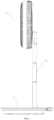
FIG. 1 is a structural reference view of a storable fan in a used state according to an embodiment of the present disclosure; -
FIG. 2 is a structural exploded view of a storable fan according to an embodiment of the present disclosure; -
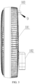
FIG. 3 is a structural reference view of a fan head in a storable fan according to an embodiment of the present disclosure; -
FIG. 4 is a partially enlarged view of D inFIG. 3 ; -
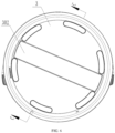
FIG. 5 is a structural reference view of a top of a base in a storable fan according to an embodiment of the present disclosure; -
FIG. 6 is a structural reference view of a bottom of a base in a storable fan according to an embodiment of the present disclosure; -
FIG. 7 is a reference view of a storage process for a fan head and a base in a storable fan according to an embodiment of the present disclosure; -
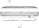
FIG. 8 is a structural reference view of a stored state for a fan head and a base in a storable fan according to an embodiment of the present disclosure; -
FIG. 9 is a structural reference view of a stored state for a support rod and a base in a storable fan according to an embodiment of the present disclosure; -
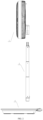
FIG. 10 is a structural reference view of a storable fan in a used state according to an embodiment of the present disclosure; -
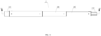
FIG. 11 is a side view of an extended state of a support rod in a storable fan according to an embodiment of the present disclosure; -
FIG. 12 is a sectional view along A-A inFIG. 11 ; -
FIG. 13 is a partially enlarged view of E inFIG. 12 ; -
FIG. 14 is a front view of an extended state of a support rod in a storable fan according to an embodiment of the present disclosure; -
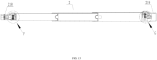
FIG. 15 is a sectional view along B-B inFIG. 14 ; -
FIG. 16 is a partially enlarged view of F inFIG. 15 ; -
FIG. 17 is a partially enlarged view of G inFIG. 15 ; -
FIG. 18 is a front view of a retracted state of a support rod in a storable fan according to an embodiment of the present disclosure; -
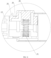
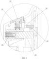
FIG. 19 is a sectional view along C-C inFIG. 6 ; -
FIG. 20 is a partially enlarged view of G inFIG. 18 ; -
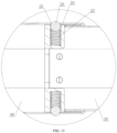
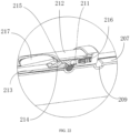
FIG. 21 is a structural reference view of a specific implementation for a locating structure of a telescopic rod in an unlocked state according to an embodiment of the present disclosure; and -
FIG. 22 is a structural reference view of a specific implementation for a locating structure of a telescopic rod in a locked state according to an embodiment of the present disclosure. - In the figures:
1: fan head, 101: guard, 102: connecting segment, 103: locking rod, 104: stationary blocking portion, 2: support rod, 201: first pressing plate, 202: first engagement member, 203: first button, 204: second pressing plate, 205: second engagement member, 206: second button, 207: first rod, 208: second rod, 209: first groove, 210: limiting hole, 211: locating pin, 212: first wall, 213: second wall, 214: slider, 215: second groove, 216: third elastic piece, 217: third button, 218: first insertion portion, 219: second insertion portion, 220: fourth elastic piece, 221: fifth elastic piece, 222: locating hole, 223: accommodating groove, 224: propping bead, 225: sixth elastic piece, 226: mounting groove, 3: base, 301: first accommodating groove, 302: second accommodating groove, 303: fixing hole, 304: movable blocking portion, 305: third locking piece, 306: connecting rod, 307: fourth button, 308: first elastic piece, 309: propping member, 310: second elastic piece, and 311: locking hole. - To enable those skilled in the art to better understand the solutions of the present disclosure, the technical solutions in the embodiments of the present disclosure will be clearly and completely described below in conjunction with the accompanying drawings in the embodiments of the present disclosure. Obviously, the described embodiments are only a part of, not all of, the embodiments of the present invention, which is solely defined by the appended claims.
- It should be noted that the terms "first", "second", and so on in the description and claims of this application and in the above accompanying drawings are intended to distinguish between similar objects but do not necessarily indicate a specific order or sequence. It should be understood that the data termed in such a way is interchangeable in proper circumstances such that the embodiments of the present disclosure described herein can be implemented in other orders than the order illustrated or described herein. Moreover, the terms "include", "contain", and any other variants mean to cover the non-exclusive inclusion, for example, a process, method, system, product, or device that includes a list of steps or units is not necessarily limited to those steps or units which are clearly listed, but may include other steps or units which are not expressly listed or inherent to such a process, method, system, product, or device.
- In the present disclosure, the terms such as "upper", "inner", "middle", "outer", "front", "rear", and "behind" indicate the orientation or positional relationship shown in the accompanying drawings. These terms are mainly intended to better describe the present disclosure and embodiments thereof, rather than to define that the devices or components indicated must have the specific orientation or be constructed and operated in the specific orientation.
- Besides, some of the terms mentioned above may be used to indicate other meanings in addition to indicating the orientation or positional relations. For example, the term "upper" may also be used to indicate an attachment relationship or a connection relationship in some cases. Those of ordinary skill in the art may understand specific meanings of these terms in the present disclosure based on a specific situation.
- In addition, the terms "provided with", "connected to" and "fixed to" should be understood in a board sense. For example, "connection" may be a fixed connection, a removable connection, or integration; may be a mechanical connection or an electrical connection; may be a direct connection or an indirect connection implemented by using an intermediate medium; or may be intercommunication between two components, elements or components. Those of ordinary skill in the art may understand specific meanings of the foregoing terms in the present disclosure based on a specific situation.
- The present disclosure will be described in detail below with reference to
FIGS. 1-21 and embodiments. - As shown in
FIG. 1 andFIG. 2 , the present invention provides a storable fan, includingfan head 1,support rod 2, andbase 3. Thefan head 1, thesupport rod 2, and thebase 3 are connected detachably. Firstaccommodating groove 301 and secondaccommodating groove 302 are formed in thebase 3. The storable fan has a used state and a stored state. The used state refers to a state in which various components of the fan are assembled for blowing or are ready for blowing. When the storable fan is in the used state, thefan head 1, thesupport rod 2, and thebase 3 are connected sequentially. The stored state refers to a state in which various components of the fan are arranged for storage. When the storable fan is in the stored state, thefan head 1 is stored in the firstaccommodating groove 301. Thesupport rod 2 is stored in the secondaccommodating groove 302. - According to the storable fan provided by the above embodiment, the
fan head 1, thesupport rod 2 and thebase 3 are connected detachably, for ease of detachment of the storable fan. Both thefan head 1 and thesupport rod 2 can be stored in thebase 3. The storage process can be accomplished without detaching such fasteners as screws and nuts. The storable fan is stored simply and conveniently, with a small footprint. - The first
accommodating groove 301 is formed in one side of thebase 3. The secondaccommodating groove 302 is formed in the other opposite side of thebase 3. For example, as shown inFIGS. 5-7 , the firstaccommodating groove 301 is formed in a top of thebase 3. The secondaccommodating groove 302 is formed in a bottom of thebase 3. Thefan head 1 and thesupport rod 2 can be respectively stored at two sides of thebase 3. This makes full use of a space of thebase 3, and prevents mutual interference between thefan head 1 and thesupport rod 2. - According to the storable fan provided by the embodiment of the present disclosure, specifically, detachable connection between the
fan head 1, thesupport rod 2, and thebase 3 is preferably realized by insertion. The operation is simple, convenient, and easy-to-realize. Specifically, as shown inFIGS. 11-17 , two ends of thesupport rod 2 are respectively provided withfirst insertion portion 218 andsecond insertion portion 219. Thefan head 1 includesguard 101 and connectingsegment 102 rotatably connected to theguard 101. Fixinghole 303 is formed in thebase 3. When the storable fan is in the used state, a first end and a second end of thesupport rod 2 are respectively connected to the connectingsegment 102 and the fixinghole 303. Thefirst insertion portion 218 of thesupport rod 2 is inserted with a connecting portion, while thesecond insertion portion 219 of thesupport rod 2 is inserted with the fixinghole 303. When the storable fan is in the stored state, the connectingsegment 102 is fixed in the firstaccommodating groove 301. A shape of the firstaccommodating groove 301 is matched with a contour of a connecting end. - In order to realize stable connection and convenient detachment for the two ends of the
support rod 2 with thefan head 1 and thebase 3, the two ends of thesupport rod 2 may be respectively provided with a corresponding structural component. - Optionally, as shown in
FIG. 15 andFIG. 16 , a first end of thesupport rod 2 connected to thefan head 1, namely thefirst insertion portion 218, is provided thereon with firstpressing plate 201.First engagement member 202 andfirst button 203 are provided on the firstpressing plate 201. A first engagement portion cooperated with thefirst engagement member 202 is provided on thefan head 1. By pressing thefirst button 203, the firstpressing plate 201 can drive the first engagement portion to move inward, thereby generating an acting force opposite to a movement direction. After thefirst button 203 is loosened, the firstpressing plate 201 and thefirst button 203 are restored under the acting force. Herein, the acting force may be generated by fourthelastic piece 220 between the firstpressing plate 201 and thesupport rod 2. Alternatively, the firstpressing plate 201 may further be provided as a cantilever structure integrally connected to thesupport rod 2; and the acting force is generated by deformation of the firstpressing plate 201. When the storable fan is used, thefirst button 203 at the end of thesupport rod 2 is pressed, such that the firstpressing plate 201 and thefirst engagement member 202 move inward. Thefirst insertion portion 218 at the end of thesupport rod 2 is inserted into the connectingsegment 102 of thefan head 1. After thefirst button 203 is loosened, the firstpressing plate 201 and thefirst engagement member 202 are restored reversely. Thefirst engagement member 202 is engaged with the first engagement portion on the connectingsegment 102 of thefan head 1 to realize installation and fixation for thefan head 1 and thesupport rod 2. When thefan head 1 and thesupport rod 2 are to be detached, thefirst button 203 at the end of thesupport rod 2 is pressed, such that the firstpressing plate 201 and thefirst engagement member 202 move inward, and thefirst engagement member 202 is separated from the first engagement portion. Thefirst insertion portion 218 at the end of thesupport rod 2 is moved out of the connectingsegment 102 of thefan head 1. After thefirst button 203 is loosened, the firstpressing plate 201 and thefirst engagement member 202 are restored reversely to realize detachment for thefan head 1 and thesupport rod 2. - Likewise, as shown in
FIG. 15 andFIG. 17 , a second end of thesupport rod 2 connected to thebase 3, namely thesecond insertion portion 219, is provided thereon with secondpressing plate 204.Second engagement member 205 andsecond button 206 are provided on the secondpressing plate 204. A second engagement portion cooperated with thesecond engagement member 205 is provided in the fixinghole 303 of thebase 3. By pressing thesecond button 206, the secondpressing plate 204 can drive the second engagement portion to move inward, thereby generating an acting force opposite to a movement direction. After thesecond button 206 is loosened, the secondpressing plate 204 and thesecond button 206 are restored under the acting force. Herein, the acting force may be generated by fifthelastic piece 221 between the secondpressing plate 204 and thesupport rod 2. Alternatively, the secondpressing plate 204 may further be provided as a cantilever structure integrally connected to thesupport rod 2; and the acting force is generated by deformation of the secondpressing plate 204. When the storable fan is used, thesecond button 206 at the end of thesupport rod 2 is pressed, such that the secondpressing plate 204 and thesecond engagement member 205 move inward. Thesecond insertion portion 219 at the end of thesupport rod 2 is inserted into the fixinghole 303 of thebase 3. After thesecond button 206 is loosened, the secondpressing plate 204 and thesecond engagement member 205 are restored reversely. Thesecond engagement member 205 is engaged with the second engagement portion in the fixinghole 303 of thebase 3 to realize installation and fixation for thebase 3 and thesupport rod 2. When thebase 3 and thesupport rod 2 are to be detached, thesecond button 206 at the end of thesupport rod 2 is pressed, such that the secondpressing plate 204 and thesecond engagement member 205 move inward, and thesecond engagement member 205 is separated from the second engagement portion. Thesecond insertion portion 219 at the end of thesupport rod 2 is moved out of the fixinghole 303 of thebase 3. After thefirst button 206 is loosened, the firstpressing plate 204 and thefirst engagement member 205 are restored reversely to realize detachment for thebase 3 and thesupport rod 2. - On the basis of the above implementations, for the sake of more convenient and quicker installation, as shown in
FIG. 16 andFIG. 17 , an end of thefirst engagement member 202 away from the second end (the second insertion portion 219) of thesupport rod 2 is provided with an outward wedge-shaped surface. With the wedge-shaped surface, when thefirst insertion portion 218 of thesupport rod 2 is inserted into the connectingsegment 102 of thefan head 1, thefirst button 203 is unnecessarily pressed. During insertion, the connectingsegment 102 is interfered with the wedge-shaped surface of thefirst engagement member 202, and thefirst engagement member 202 and the firstpressing plate 201 are moved inward forcibly. After the insertion is in place, the wedge-shaped surface of thefirst engagement member 202 is released from the connectingsegment 102, and the first engagement member moves reversely to engage with the first engagement portion. Likewise, an end of thesecond engagement member 205 away from the first end (the first insertion portion 218) of thesupport rod 2 is provided with an outward wedge-shaped surface. With the wedge-shaped surface, when thesecond insertion portion 219 of thesupport rod 2 is inserted into the fixinghole 303 of thebase 3, thesecond button 206 is unnecessarily pressed. During insertion, an inner wall of the fixinghole 303 is interfered with the wedge-shaped surface of thesecond engagement member 205, and thesecond engagement member 205 and the secondpressing plate 204 are moved inward forcibly. After the insertion is in place, the wedge-shaped surface of thesecond engagement member 205 is released from the inner wall of the fixinghole 303, and thesecond engagement member 205 moves reversely to engage with the second engagement portion. With the wedge-shaped surfaces on thefirst engagement member 202 and thesecond engagement member 205, when the fan is assembled, various structural components can be fixedly connected without pressing. The structural components can also be detached only by pressing. Therefore, the one-button operation is realized. - When the
fan head 1 is stored in the firstaccommodating groove 301 of thebase 3, the connectingsegment 102 of thefan head 1 is attached to theguard 101 by rotating. The connectingsegment 102 is then placed into the firstaccommodating groove 301, thereby realizing storage of thefan head 1. In this case, theguard 101 may rotate relative to the connectingsegment 102 to make an overall structure of thefan head 1 and thebase 3 unstable. In view of this, as shown inFIG. 3 ,FIG. 4 andFIG. 7 , a first locking piece is provided on thefan head 1. A second locking piece is provided on thebase 3. In the stored state shown inFIG. 8 , the first locking piece is locked with the second locking piece. Specifically, the first locking piece is provided on theguard 101. Through cooperation between the first locking piece and the second locking piece, thefan head 1 and thebase 3 can further be limited. This prevents theguard 101 from moving relative to thebase 3 to make the storage structure unstable. Preferably, as shown inFIG. 4 andFIG. 5 , the first locking piece is lockingrod 103.Stationary blocking portion 104 is provided on a surface of the lockingrod 103 along the radial direction of the lockingrod 103. The second locking piece is lockinghole 311 formed in thebase 3.Movable blocking portion 304 is provided on an inner wall of thelocking hole 311. Themovable blocking portion 304 is extended into thelocking hole 311 under an elastic force. When the lockingrod 103 is inserted into thelocking hole 311, thestationary blocking portion 104 pushes away themovable blocking portion 304 and is inserted under the movable blocking portion. The blocking portion is restored under the elastic force to realize engagement between themovable blocking portion 304 and thestationary blocking portion 104, as well as locking between the lockingrod 103 and thelocking hole 311. When the lockingrod 103 is to be moved out of thelocking hole 311, the lockingrod 103 is moved outward by an external force. With the external force, thestationary blocking portion 104 pushes themovable blocking portion 304 forcibly to realize separation between the lockingrod 103 and thelocking hole 311. More preferably, as shown inFIG. 19 andFIG. 20 , themovable blocking portion 304 is connected tofourth button 307 through connectingrod 306 rotatably connected to thebase 3. Thefourth button 307 is provided at a side of thebase 3. Firstelastic piece 308 is provided between thefourth button 307 and thebutton 3. By pressing thefourth button 307 to overcome an elastic restoring force of the firstelastic piece 308, the connectingrod 306 rotates, thereby driving themovable blocking portion 304 to move toward a direction away from a center of thelocking hole 311. Therefore, the limitation between themovable blocking portion 304 and thestationary blocking portion 104 can be released. After thefourth button 307 is loosened, thefourth button 307 is restored under an action of the firstelastic piece 308. In addition, proppingmember 309 is provided at a bottom of thelocking hole 311. The proppingmember 309 is connected to thebase 3 through secondelastic piece 310. The lockingrod 103 abuts against the proppingmember 309 when entering thelocking hole 311 in assembly, so as to overcome an elastic restoring force of the secondelastic piece 310. After thefourth button 307 is pressed for unlocking, the secondelastic piece 310 can pop up thefan head 1 automatically through the elastic restoring force. Therefore, the operation is more convenient. - In some implementations, as shown in
FIG. 5 andFIG. 7 ,third locking piece 305 is provided in the firstaccommodating groove 301. The connectingsegment 102 is locked with thethird locking piece 305 in the stored state, such that a connection strength between thebase 3 and the connectingsegment 102 can be increased. Thethird locking piece 305 is preferably an elastic gripping jaw structure. An inner wall of the elastic gripping jaw structure is matched with an external contour of the connectingsegment 102. The elastic gripping jaw structure may be provided at one end of the firstaccommodating groove 301. During storage, one end of the connectingsegment 102 can be inserted into the elastic gripping jaw structure. The first locking piece is then connected to the second locking piece. - In some implementations, the
support rod 2 is a telescopic rod shown inFIGS. 11-18 . On one hand, when the storable fan is in the used state, as shown inFIG. 10 , the height of the electric fan can be adjusted through the telescopic rod, such that thefan head 1 works at different heights to meet actual requirements of a user. On the other hand, when the storable fan is in the stored state, thesupport rod 2 is retracted as shown inFIG. 18 , for better storage of thesupport rod 2. As shown inFIG. 9 , the secondaccommodating groove 302 in thebase 3 is matched with the contour of thesupport rod 2 in the retracted state. - On the basis of the above implementations, the specific structure of the
support rod 2 may be various forms of the telescopic rod in the prior art, provided that the objective of the present disclosure can be realized. - Optionally, as shown in
FIG. 21 andFIG. 22 , thesupport rod 2 includesfirst rod 207 andsecond rod 208 connected to each other. Thefirst rod 207 is nested in thesecond rod 208. A plurality offirst grooves 209 are formed in an outer wall of thefirst rod 207 along the axial direction of thefirst rod 207. A control assembly, limitinghole 210 and locatingpin 211 are provided on thesecond rod 208. The locatingpin 211 is located in the limitinghole 210. The control assembly is configured to limit the locatingpin 211 in a locked state of being simultaneously engaged in thefirst groove 209 and the limitinghole 210. The control assembly is further configured to release the locked state of the locatingpin 211. Specifically, thesecond rod 208 includesfirst wall 212 andsecond wall 213. Thefirst rod 207 is sleeved in thesecond wall 213. The control assembly includesslider 214 and thirdelastic piece 216. Theslider 214 is slidably provided between thefirst wall 212 and thesecond wall 213. A side of theslider 214 facing thesecond wall 213 is provided withsecond groove 215. When the limitinghole 210 directly faces thefirst groove 209, theslider 214 limits the locatingpin 211 in the limitinghole 210 and thefirst groove 209 simultaneously under an elastic force of the thirdelastic piece 216. When the storable fan is used, theslider 214 is pushed to overcome an elastic restoring force of the thirdelastic piece 216 to slide in mountinggroove 226 between thefirst wall 212 and thesecond wall 213. As shown inFIG. 21 , at an extreme position, thesecond groove 215 in theslider 214 can directly face the limitinghole 210 in thesecond wall 213. By moving thefirst rod 207, the outer wall of thefirst rod 207 pushes the locatingpin 211 to move to thesecond groove 215 of theslider 214. In this case, thefirst rod 207 and thesecond rod 208 cannot be locked. When somefirst groove 209 in thefirst rod 207 directly faces the limitinghole 210, the locatingpin 211 can be located in the limitinghole 210 and thefirst groove 209 simultaneously. If theslider 214 is not pushed, theslider 214 is restored under the thirdelastic piece 216, as shown inFIG. 22 . In this case, a bottom of theslider 214 abuts against the locatingpin 211, the locatingpin 211 cannot be released completely from thefirst groove 209, and thefirst rod 207 and thesecond rod 208 are locked through the locatingpin 211. When the locking is to be released, theslider 214 is pushed, such that thesecond groove 215 directly faces the limitinghole 210. Through thefirst rod 207 moving axially relative to thesecond rod 208, the locatingpin 211 is released from thefirst groove 209 to enter thesecond groove 215, as shown inFIG. 21 . In order to realize the above action, a sum of a thickness of theslider 214 and a diameter of the locatingpin 211 is greater than a distance between an inner wall of thefirst wall 212 and an inner wall of thesecond wall 213. When theslider 214 is attached to thefirst wall 212, a distance between a bottom of thefirst groove 209 and the inner wall of thesecond wall 213 is not less than the diameter of the locatingpin 211. In order to push theslider 214 more conveniently,third button 217 can be provided on thesecond rod 208. Thethird button 217 and theslider 214 are in sliding fit through an oblique plane. By pressing thethird button 217, theslider 214 can be pushed to slide. After thethird button 217 is loosened, the thirdelastic piece 216 pushes theslider 214 to move reversely, thereby pushing thethird button 217 for restoration. Through the above structure, the length of the telescopic rod is adjusted conveniently, and the telescopic rod in the locked state is stable. Therefore, the operation is more humanized. - Optionally, as shown in the figure, the
support rod 2 includesfirst rod 207 andsecond rod 208 connected to each other. Thefirst rod 207 is nested in thesecond rod 208. Locatinghole 222 is formed in a wall of thesecond rod 208. A wall of thefirst rod 207 is recessed to form anaccommodating groove 223. Proppingbead 224 and sixthelastic piece 225 are provided in theaccommodating groove 223. The sixthelastic piece 225 is provided between the proppingbead 224 and a bottom of theaccommodating groove 223. Through the sixthelastic piece 225, the proppingbead 224 abuts against an inner wall of thesecond rod 208 or the locatinghole 222. A diameter of the locatinghole 222 is less than a diameter of the proppingbead 224. - The storable fan according to the above embodiment may further includes other necessary assemblies or structures, and the corresponding arrangement positions and connection relationships may refer to structures of related apparatuses in the prior art. The connection relations, operations and working principles of the structures not mentioned above are known to those of ordinary skill in the art, and will not be described in detail herein.
- Different embodiments are described progressively herein. Each embodiment focuses on the differences from other embodiments, and mutual reference may be made to the same and similar parts of such examples.
- The above are only specific implementations of the present invention, such that those skilled in the art can understand or realize the present invention.
- Various modifications to these embodiments are readily apparent to a person skilled in the art, and the generic principles defined herein may be practiced in other embodiments without departing from the scope of the present invention. Thus, the present invention is not limited to the embodiments shown herein but falls within the widest scope defined by the appended claims.
Claims (10)
- A storable fan, comprising a fan head (1), a support rod (2) and a base (3) that are connected detachably, wherein a first accommodating groove (301) and a second accommodating groove (302) are formed in the base (3), and the storable fan has a used state and a stored state; when the storable fan is in the used state, the fan head (1), the support rod (2) and the base (3) are connected sequentially; and when the storable fan is in the stored state, the fan head (1) is stored in the first accommodating groove (301), and the support rod (2) is stored in the second accommodating groove (302);the fan head (1) comprises a guard (101) and a connecting segment (102) rotatably connected to the guard (101); and a fixing hole (303) is formed in the base (3); when the storable fan is in the used state, a first end and a second end of the support rod (2) are respectively connected to the connecting segment (102) and the fixing hole (303); andthe fixing hole (303) and the first accommodating groove (301) are formed in a same side of the base (3), and the second accommodating groove (302) is formed in the other opposite side of the base (3);characterized in thatwhen the storable fan is in the stored state, the connecting segment (102) is fixed in the first accommodating groove (301).
- The storable fan according to claim 1, characterized in that the support rod (2) is a telescopic rod.
- The storable fan according to claim 2, characterized in that the support rod (2) is retracted in the stored state.
- The storable fan according to claim 1, characterized in that the first end of the support rod (2) connected to the fan head (1) is provided with a first pressing plate (201), a first engagement member (202) and a first button (203) are provided on the first pressing plate (201), and a first engagement portion cooperated with the first engagement member (202) is provided on the fan head (1); and/or
the second end of the support rod (2) connected to the base (3) is provided with a second pressing plate (204), a second engagement member (205) and a second button (206) are provided on the second pressing plate (204), and a second engagement portion cooperated with the second engagement member (205) is provided on the base (3). - The storable fan according to claim 4, characterized in that an end of the first engagement member (202) facing the first end of the support rod (2) is provided with an outward wedge-shaped surface; and/or
an end of the second engagement member (205) facing the second end of the support rod (2) is provided with an outward wedge-shaped surface. - The storable fan according to claim 1, characterized in that a first locking piece is provided on the fan head (1), a second locking piece is provided on the base (3), and in the stored state, the first locking piece is locked with the second locking piece.
- The storable fan according to claim 6, characterized in that the first locking piece is a locking rod (103), a stationary blocking portion (104) is provided on a surface of the locking rod (103) along a radial direction of the locking rod (103), the second locking piece is a locking hole (311) formed in the base (3), a movable blocking portion (304) is provided on an inner wall of the locking hole (311), and the movable blocking portion (304) is extended into the locking hole (311) under an elastic force.
- The storable fan according to claim 1, characterized in that a third locking piece (305) is provided in the first accommodating groove (301), and in the stored state, the connecting segment (102) is locked with the third locking piece (305).
- The storable fan according to claim 2, characterized in that the support rod (2) comprises a first rod (207) and a second rod (208) connected to each other; the first rod (207) is nested in the second rod (208); a plurality of first grooves (209) are formed in an outer wall of the first rod (207) along an axial direction of the first rod (207); a control assembly, a limiting hole (210) and a locating pin (211) are provided on the second rod (208); the locating pin (211) is located in the limiting hole (210); and the control assembly is configured to limit the locating pin (211) in a locked state of being simultaneously engaged in the first groove (209) and the limiting hole (210) or release the locked state of the locking pin (211).
- The storable fan according to claim 9, characterized in that the second rod (208) comprises a first wall (212) and a second wall (213); the first rod (207) is sleeved in the second wall (213); the control assembly comprises a slider (214) and a third elastic piece (216); the slider (214) is slidably provided between the first wall (212) and the second wall (213); a side of the slider (214) facing the second wall (213) is provided with a second groove (215); and when the limiting hole (210) directly faces the first groove (209), the slider (214) limits the locating pin (211) in the limiting hole (210) and the first groove (209) simultaneously under an elastic force of the third elastic piece (216).
Applications Claiming Priority (2)
| Application Number | Priority Date | Filing Date | Title |
|---|---|---|---|
| CN202022456928.4U CN217440321U (en) | 2020-10-29 | 2020-10-29 | Storable fan |
| PCT/CN2020/127654 WO2022088237A1 (en) | 2020-10-29 | 2020-11-10 | Storable fan |
Publications (4)
| Publication Number | Publication Date |
|---|---|
| EP4227540A1 EP4227540A1 (en) | 2023-08-16 |
| EP4227540A4 EP4227540A4 (en) | 2024-02-21 |
| EP4227540C0 EP4227540C0 (en) | 2025-01-01 |
| EP4227540B1 true EP4227540B1 (en) | 2025-01-01 |
Family
ID=75034955
Family Applications (1)
| Application Number | Title | Priority Date | Filing Date |
|---|---|---|---|
| EP20959397.9A Active EP4227540B1 (en) | 2020-10-29 | 2020-11-10 | Storable fan |
Country Status (5)
| Country | Link |
|---|---|
| US (1) | US11867200B2 (en) |
| EP (1) | EP4227540B1 (en) |
| JP (1) | JP7342107B2 (en) |
| KR (1) | KR102564935B1 (en) |
| CN (1) | CN112567138B (en) |
Families Citing this family (6)
| Publication number | Priority date | Publication date | Assignee | Title |
|---|---|---|---|---|
| CN118793642A (en) * | 2023-04-14 | 2024-10-18 | 广东美的环境电器制造有限公司 | Fan, fan head and fan assembly method |
| CN118793640A (en) * | 2023-04-14 | 2024-10-18 | 广东美的环境电器制造有限公司 | fan |
| US20250160316A1 (en) * | 2023-06-02 | 2025-05-22 | Shenzhen Maichen Suchuang Technology Co., Ltd. | Telescopic insect-and-fly repellent device |
| CN116716714B (en) * | 2023-07-25 | 2025-08-26 | 珠海格力电器股份有限公司 | Clothes rod assembly and device having the same |
| USD1118886S1 (en) * | 2024-12-16 | 2026-03-17 | Airmate Electrical (Shen Zhen) Co., Ltd | Floor fan |
| USD1105400S1 (en) * | 2025-02-10 | 2025-12-09 | E. Mishan & Sons, Inc. | Folding fan |
Family Cites Families (22)
| Publication number | Priority date | Publication date | Assignee | Title |
|---|---|---|---|---|
| JPS58191494U (en) * | 1982-06-14 | 1983-12-20 | 株式会社東芝 | Fan height adjustment device |
| JPS63158255U (en) * | 1987-04-02 | 1988-10-17 | ||
| JPH0436787Y2 (en) * | 1988-12-27 | 1992-08-31 | ||
| US6139270A (en) * | 1999-02-24 | 2000-10-31 | Liao; Chin-I | Electric fan |
| KR20100124454A (en) | 2009-05-19 | 2010-11-29 | 이순 | Electric fan |
| CN101813112A (en) * | 2010-05-10 | 2010-08-25 | 沈盘根 | Telescopic tube |
| CN201723537U (en) | 2010-06-13 | 2011-01-26 | 马卫宏 | Telescopic rod |
| CN104514733B (en) | 2013-09-26 | 2017-01-18 | 珠海格力电器股份有限公司 | Standard fan |
| JP5739038B1 (en) | 2013-11-11 | 2015-06-24 | アイリスオーヤマ株式会社 | Fan |
| CN104389820B (en) * | 2014-11-04 | 2017-10-13 | 珠海格力电器股份有限公司 | Upright post connecting structure and electric fan |
| CN204239295U (en) | 2014-11-18 | 2015-04-01 | 广东美的环境电器制造有限公司 | Fan |
| CN106015041A (en) | 2016-06-17 | 2016-10-12 | 杭州飞鱼工业设计有限公司 | Vertical type electric fan |
| CN207728587U (en) * | 2017-12-24 | 2018-08-14 | 江南大学 | A kind of intake type stand fan |
| US11162513B2 (en) * | 2018-12-20 | 2021-11-02 | Zhejiang Joyo Electric Appliance Technology Co,. Ltd. | Adjustable stand fan |
| CN110469793B (en) * | 2019-01-25 | 2020-10-27 | 深圳叠品科技有限公司 | A new type of folding device and its fan and table lamp |
| WO2020151102A1 (en) | 2019-01-25 | 2020-07-30 | 深圳市全天拍科技有限公司 | Foldable electric fan |
| CN110285085A (en) | 2019-07-12 | 2019-09-27 | 中山市春凯电器有限公司 | Folding storage type barrel fan |
| CN210509656U (en) | 2019-08-06 | 2020-05-12 | 东莞市格尚电器有限公司 | Foldable portable fan |
| CN210565256U (en) | 2019-09-11 | 2020-05-19 | 宋胜强 | Folding oscillating fan |
| CN210949218U (en) | 2019-11-22 | 2020-07-07 | 佛山市沃尼思通环境电器有限公司 | Foldable fan |
| JP3225783U (en) | 2020-01-22 | 2020-04-02 | 株式会社住本製作所 | Portable electric fan |
| US11378100B2 (en) * | 2020-11-30 | 2022-07-05 | E. Mishan & Sons, Inc. | Oscillating portable fan with removable grille |
-
2020
- 2020-11-10 JP JP2021506980A patent/JP7342107B2/en active Active
- 2020-11-10 US US18/250,999 patent/US11867200B2/en active Active
- 2020-11-10 EP EP20959397.9A patent/EP4227540B1/en active Active
- 2020-11-10 KR KR1020217004106A patent/KR102564935B1/en active Active
- 2020-11-10 CN CN202080002845.8A patent/CN112567138B/en active Active
Also Published As
| Publication number | Publication date |
|---|---|
| EP4227540A1 (en) | 2023-08-16 |
| EP4227540A4 (en) | 2024-02-21 |
| EP4227540C0 (en) | 2025-01-01 |
| US11867200B2 (en) | 2024-01-09 |
| CN112567138B (en) | 2022-12-06 |
| KR102564935B1 (en) | 2023-08-08 |
| US20230392614A1 (en) | 2023-12-07 |
| KR20220058834A (en) | 2022-05-10 |
| JP7342107B2 (en) | 2023-09-11 |
| CN112567138A (en) | 2021-03-26 |
| JP2023503727A (en) | 2023-02-01 |
Similar Documents
| Publication | Publication Date | Title |
|---|---|---|
| US11867200B2 (en) | Storable fan | |
| CN110652104B (en) | Multifunctional mounting bracket | |
| CN209051226U (en) | A kind of portable easel of novel and multifunctional design | |
| CN114856219A (en) | Prefabricated wallboard installation device | |
| US20100018086A1 (en) | Retractable iron and ironing board assembly | |
| CN217440321U (en) | Storable fan | |
| CN219762669U (en) | Extensible containing box | |
| CN210672522U (en) | Multifunctional folding table | |
| CN214072346U (en) | Automatic folding dining table of locking | |
| CN215737538U (en) | Table with turnover table board | |
| CN222149799U (en) | Frying and baking machine with storable handle | |
| CN222941953U (en) | Shelf structure of computer desk and computer desk | |
| CN211625449U (en) | Mounting structure, installation casing and heating installation | |
| CN219047745U (en) | Storage table with rotary panel | |
| CN222941941U (en) | Foldable desk plate structure and computer desk | |
| CN109177651B (en) | Portable telescopic castor | |
| CN220402156U (en) | Coupling assembling, electronic equipment's casing and electronic equipment | |
| CN222941947U (en) | Lifting device for lifting table and lifting table | |
| CN219422421U (en) | Folding table top capable of being mounted on wall | |
| CN222367790U (en) | Auxiliary workbench and anesthesia machine | |
| CN219000094U (en) | Oven and movable side table structure | |
| CN213403107U (en) | Support component | |
| CN220881803U (en) | Fixed framework for grinding brush | |
| CN117322821A (en) | Cleaning tool | |
| CN221465886U (en) | Chuck assembly of soft light box and soft light box |
Legal Events
| Date | Code | Title | Description |
|---|---|---|---|
| STAA | Information on the status of an ep patent application or granted ep patent |
Free format text: STATUS: THE INTERNATIONAL PUBLICATION HAS BEEN MADE |
|
| PUAI | Public reference made under article 153(3) epc to a published international application that has entered the european phase |
Free format text: ORIGINAL CODE: 0009012 |
|
| STAA | Information on the status of an ep patent application or granted ep patent |
Free format text: STATUS: REQUEST FOR EXAMINATION WAS MADE |
|
| 17P | Request for examination filed |
Effective date: 20230510 |
|
| AK | Designated contracting states |
Kind code of ref document: A1 Designated state(s): AL AT BE BG CH CY CZ DE DK EE ES FI FR GB GR HR HU IE IS IT LI LT LU LV MC MK MT NL NO PL PT RO RS SE SI SK SM TR |
|
| DAV | Request for validation of the european patent (deleted) | ||
| DAX | Request for extension of the european patent (deleted) | ||
| A4 | Supplementary search report drawn up and despatched |
Effective date: 20240122 |
|
| RIC1 | Information provided on ipc code assigned before grant |
Ipc: F04D 29/64 20060101ALI20240116BHEP Ipc: F04D 29/60 20060101ALI20240116BHEP Ipc: F04D 19/00 20060101ALI20240116BHEP Ipc: F04D 25/08 20060101AFI20240116BHEP |
|
| GRAP | Despatch of communication of intention to grant a patent |
Free format text: ORIGINAL CODE: EPIDOSNIGR1 |
|
| STAA | Information on the status of an ep patent application or granted ep patent |
Free format text: STATUS: GRANT OF PATENT IS INTENDED |
|
| RIC1 | Information provided on ipc code assigned before grant |
Ipc: F04D 29/64 20060101ALI20240626BHEP Ipc: F04D 29/60 20060101ALI20240626BHEP Ipc: F04D 19/00 20060101ALI20240626BHEP Ipc: F04D 25/08 20060101AFI20240626BHEP |
|
| INTG | Intention to grant announced |
Effective date: 20240717 |
|
| GRAS | Grant fee paid |
Free format text: ORIGINAL CODE: EPIDOSNIGR3 |
|
| GRAA | (expected) grant |
Free format text: ORIGINAL CODE: 0009210 |
|
| STAA | Information on the status of an ep patent application or granted ep patent |
Free format text: STATUS: THE PATENT HAS BEEN GRANTED |
|
| AK | Designated contracting states |
Kind code of ref document: B1 Designated state(s): AL AT BE BG CH CY CZ DE DK EE ES FI FR GB GR HR HU IE IS IT LI LT LU LV MC MK MT NL NO PL PT RO RS SE SI SK SM TR |
|
| REG | Reference to a national code |
Ref country code: GB Ref legal event code: FG4D |
|
| REG | Reference to a national code |
Ref country code: CH Ref legal event code: EP |
|
| REG | Reference to a national code |
Ref country code: DE Ref legal event code: R096 Ref document number: 602020044363 Country of ref document: DE |
|
| REG | Reference to a national code |
Ref country code: IE Ref legal event code: FG4D |
|
| U01 | Request for unitary effect filed |
Effective date: 20250123 |
|
| U07 | Unitary effect registered |
Designated state(s): AT BE BG DE DK EE FI FR IT LT LU LV MT NL PT RO SE SI Effective date: 20250130 |
|
| PG25 | Lapsed in a contracting state [announced via postgrant information from national office to epo] |
Ref country code: PL Free format text: LAPSE BECAUSE OF FAILURE TO SUBMIT A TRANSLATION OF THE DESCRIPTION OR TO PAY THE FEE WITHIN THE PRESCRIBED TIME-LIMIT Effective date: 20250101 |
|
| PG25 | Lapsed in a contracting state [announced via postgrant information from national office to epo] |
Ref country code: ES Free format text: LAPSE BECAUSE OF FAILURE TO SUBMIT A TRANSLATION OF THE DESCRIPTION OR TO PAY THE FEE WITHIN THE PRESCRIBED TIME-LIMIT Effective date: 20250101 |
|
| PG25 | Lapsed in a contracting state [announced via postgrant information from national office to epo] |
Ref country code: IS Free format text: LAPSE BECAUSE OF FAILURE TO SUBMIT A TRANSLATION OF THE DESCRIPTION OR TO PAY THE FEE WITHIN THE PRESCRIBED TIME-LIMIT Effective date: 20250501 Ref country code: NO Free format text: LAPSE BECAUSE OF FAILURE TO SUBMIT A TRANSLATION OF THE DESCRIPTION OR TO PAY THE FEE WITHIN THE PRESCRIBED TIME-LIMIT Effective date: 20250401 |
|
| PG25 | Lapsed in a contracting state [announced via postgrant information from national office to epo] |
Ref country code: HR Free format text: LAPSE BECAUSE OF FAILURE TO SUBMIT A TRANSLATION OF THE DESCRIPTION OR TO PAY THE FEE WITHIN THE PRESCRIBED TIME-LIMIT Effective date: 20250101 |
|
| PG25 | Lapsed in a contracting state [announced via postgrant information from national office to epo] |
Ref country code: GR Free format text: LAPSE BECAUSE OF FAILURE TO SUBMIT A TRANSLATION OF THE DESCRIPTION OR TO PAY THE FEE WITHIN THE PRESCRIBED TIME-LIMIT Effective date: 20250402 |
|
| PG25 | Lapsed in a contracting state [announced via postgrant information from national office to epo] |
Ref country code: CZ Free format text: LAPSE BECAUSE OF FAILURE TO SUBMIT A TRANSLATION OF THE DESCRIPTION OR TO PAY THE FEE WITHIN THE PRESCRIBED TIME-LIMIT Effective date: 20250101 |
|
| PG25 | Lapsed in a contracting state [announced via postgrant information from national office to epo] |
Ref country code: SM Free format text: LAPSE BECAUSE OF FAILURE TO SUBMIT A TRANSLATION OF THE DESCRIPTION OR TO PAY THE FEE WITHIN THE PRESCRIBED TIME-LIMIT Effective date: 20250101 |
|
| PG25 | Lapsed in a contracting state [announced via postgrant information from national office to epo] |
Ref country code: SK Free format text: LAPSE BECAUSE OF FAILURE TO SUBMIT A TRANSLATION OF THE DESCRIPTION OR TO PAY THE FEE WITHIN THE PRESCRIBED TIME-LIMIT Effective date: 20250101 |
|
| PLBE | No opposition filed within time limit |
Free format text: ORIGINAL CODE: 0009261 |
|
| STAA | Information on the status of an ep patent application or granted ep patent |
Free format text: STATUS: NO OPPOSITION FILED WITHIN TIME LIMIT |
|
| 26N | No opposition filed |
Effective date: 20251002 |
|
| U20 | Renewal fee for the european patent with unitary effect paid |
Year of fee payment: 6 Effective date: 20251124 |