EP4227225A1 - Powder supply device, and am device using powder supply device - Google Patents
Powder supply device, and am device using powder supply device Download PDFInfo
- Publication number
- EP4227225A1 EP4227225A1 EP21877316.6A EP21877316A EP4227225A1 EP 4227225 A1 EP4227225 A1 EP 4227225A1 EP 21877316 A EP21877316 A EP 21877316A EP 4227225 A1 EP4227225 A1 EP 4227225A1
- Authority
- EP
- European Patent Office
- Prior art keywords
- powder
- valve
- main body
- supply
- passage
- Prior art date
- Legal status (The legal status is an assumption and is not a legal conclusion. Google has not performed a legal analysis and makes no representation as to the accuracy of the status listed.)
- Pending
Links
Images


Classifications
-
- B—PERFORMING OPERATIONS; TRANSPORTING
- B22—CASTING; POWDER METALLURGY
- B22F—WORKING METALLIC POWDER; MANUFACTURE OF ARTICLES FROM METALLIC POWDER; MAKING METALLIC POWDER; APPARATUS OR DEVICES SPECIALLY ADAPTED FOR METALLIC POWDER
- B22F10/00—Additive manufacturing of workpieces or articles from metallic powder
- B22F10/20—Direct sintering or melting
- B22F10/25—Direct deposition of metal particles, e.g. direct metal deposition [DMD] or laser engineered net shaping [LENS]
-
- B—PERFORMING OPERATIONS; TRANSPORTING
- B22—CASTING; POWDER METALLURGY
- B22F—WORKING METALLIC POWDER; MANUFACTURE OF ARTICLES FROM METALLIC POWDER; MAKING METALLIC POWDER; APPARATUS OR DEVICES SPECIALLY ADAPTED FOR METALLIC POWDER
- B22F12/00—Apparatus or devices specially adapted for additive manufacturing; Auxiliary means for additive manufacturing; Combinations of additive manufacturing apparatus or devices with other processing apparatus or devices
- B22F12/50—Means for feeding of material, e.g. heads
- B22F12/52—Hoppers
-
- B—PERFORMING OPERATIONS; TRANSPORTING
- B22—CASTING; POWDER METALLURGY
- B22F—WORKING METALLIC POWDER; MANUFACTURE OF ARTICLES FROM METALLIC POWDER; MAKING METALLIC POWDER; APPARATUS OR DEVICES SPECIALLY ADAPTED FOR METALLIC POWDER
- B22F12/00—Apparatus or devices specially adapted for additive manufacturing; Auxiliary means for additive manufacturing; Combinations of additive manufacturing apparatus or devices with other processing apparatus or devices
- B22F12/50—Means for feeding of material, e.g. heads
- B22F12/57—Metering means
-
- B—PERFORMING OPERATIONS; TRANSPORTING
- B23—MACHINE TOOLS; METAL-WORKING NOT OTHERWISE PROVIDED FOR
- B23K—SOLDERING OR UNSOLDERING; WELDING; CLADDING OR PLATING BY SOLDERING OR WELDING; CUTTING BY APPLYING HEAT LOCALLY, e.g. FLAME CUTTING; WORKING BY LASER BEAM
- B23K26/00—Working by laser beam, e.g. welding, cutting or boring
- B23K26/14—Working by laser beam, e.g. welding, cutting or boring using a fluid stream, e.g. a jet of gas, in conjunction with the laser beam; Nozzles therefor
- B23K26/144—Working by laser beam, e.g. welding, cutting or boring using a fluid stream, e.g. a jet of gas, in conjunction with the laser beam; Nozzles therefor the fluid stream containing particles, e.g. powder
-
- B—PERFORMING OPERATIONS; TRANSPORTING
- B23—MACHINE TOOLS; METAL-WORKING NOT OTHERWISE PROVIDED FOR
- B23K—SOLDERING OR UNSOLDERING; WELDING; CLADDING OR PLATING BY SOLDERING OR WELDING; CUTTING BY APPLYING HEAT LOCALLY, e.g. FLAME CUTTING; WORKING BY LASER BEAM
- B23K26/00—Working by laser beam, e.g. welding, cutting or boring
- B23K26/34—Laser welding for purposes other than joining
- B23K26/342—Build-up welding
-
- B—PERFORMING OPERATIONS; TRANSPORTING
- B29—WORKING OF PLASTICS; WORKING OF SUBSTANCES IN A PLASTIC STATE IN GENERAL
- B29C—SHAPING OR JOINING OF PLASTICS; SHAPING OF MATERIAL IN A PLASTIC STATE, NOT OTHERWISE PROVIDED FOR; AFTER-TREATMENT OF THE SHAPED PRODUCTS, e.g. REPAIRING
- B29C64/00—Additive manufacturing, i.e. manufacturing of three-dimensional [3D] objects by additive deposition, additive agglomeration or additive layering, e.g. by 3D printing, stereolithography or selective laser sintering
- B29C64/10—Processes of additive manufacturing
- B29C64/141—Processes of additive manufacturing using only solid materials
- B29C64/153—Processes of additive manufacturing using only solid materials using layers of powder being selectively joined, e.g. by selective laser sintering or melting
-
- B—PERFORMING OPERATIONS; TRANSPORTING
- B29—WORKING OF PLASTICS; WORKING OF SUBSTANCES IN A PLASTIC STATE IN GENERAL
- B29C—SHAPING OR JOINING OF PLASTICS; SHAPING OF MATERIAL IN A PLASTIC STATE, NOT OTHERWISE PROVIDED FOR; AFTER-TREATMENT OF THE SHAPED PRODUCTS, e.g. REPAIRING
- B29C64/00—Additive manufacturing, i.e. manufacturing of three-dimensional [3D] objects by additive deposition, additive agglomeration or additive layering, e.g. by 3D printing, stereolithography or selective laser sintering
- B29C64/30—Auxiliary operations or equipment
- B29C64/307—Handling of material to be used in additive manufacturing
- B29C64/321—Feeding
-
- B—PERFORMING OPERATIONS; TRANSPORTING
- B33—ADDITIVE MANUFACTURING TECHNOLOGY
- B33Y—ADDITIVE MANUFACTURING, i.e. MANUFACTURING OF THREE-DIMENSIONAL [3D] OBJECTS BY ADDITIVE DEPOSITION, ADDITIVE AGGLOMERATION OR ADDITIVE LAYERING, e.g. BY 3D PRINTING, STEREOLITHOGRAPHY OR SELECTIVE LASER SINTERING
- B33Y30/00—Apparatus for additive manufacturing; Details thereof or accessories therefor
-
- B—PERFORMING OPERATIONS; TRANSPORTING
- B33—ADDITIVE MANUFACTURING TECHNOLOGY
- B33Y—ADDITIVE MANUFACTURING, i.e. MANUFACTURING OF THREE-DIMENSIONAL [3D] OBJECTS BY ADDITIVE DEPOSITION, ADDITIVE AGGLOMERATION OR ADDITIVE LAYERING, e.g. BY 3D PRINTING, STEREOLITHOGRAPHY OR SELECTIVE LASER SINTERING
- B33Y40/00—Auxiliary operations or equipment, e.g. for material handling
-
- B—PERFORMING OPERATIONS; TRANSPORTING
- B65—CONVEYING; PACKING; STORING; HANDLING THIN OR FILAMENTARY MATERIAL
- B65B—MACHINES, APPARATUS OR DEVICES FOR, OR METHODS OF, PACKAGING ARTICLES OR MATERIALS; UNPACKING
- B65B39/00—Nozzles, funnels or guides for introducing articles or materials into containers or wrappers
- B65B39/001—Nozzles, funnels or guides for introducing articles or materials into containers or wrappers with flow cut-off means, e.g. valves
- B65B39/002—Pivoting plates
-
- B—PERFORMING OPERATIONS; TRANSPORTING
- B65—CONVEYING; PACKING; STORING; HANDLING THIN OR FILAMENTARY MATERIAL
- B65B—MACHINES, APPARATUS OR DEVICES FOR, OR METHODS OF, PACKAGING ARTICLES OR MATERIALS; UNPACKING
- B65B39/00—Nozzles, funnels or guides for introducing articles or materials into containers or wrappers
- B65B39/001—Nozzles, funnels or guides for introducing articles or materials into containers or wrappers with flow cut-off means, e.g. valves
- B65B39/004—Nozzles, funnels or guides for introducing articles or materials into containers or wrappers with flow cut-off means, e.g. valves moving linearly
- B65B39/005—Nozzles, funnels or guides for introducing articles or materials into containers or wrappers with flow cut-off means, e.g. valves moving linearly transverse to flow direction
-
- B—PERFORMING OPERATIONS; TRANSPORTING
- B65—CONVEYING; PACKING; STORING; HANDLING THIN OR FILAMENTARY MATERIAL
- B65G—TRANSPORT OR STORAGE DEVICES, e.g. CONVEYORS FOR LOADING OR TIPPING, SHOP CONVEYOR SYSTEMS OR PNEUMATIC TUBE CONVEYORS
- B65G65/00—Loading or unloading
- B65G65/30—Methods or devices for filling or emptying bunkers, hoppers, tanks, or like containers, of interest apart from their use in particular chemical or physical processes or their application in particular machines, e.g. not covered by a single other subclass
- B65G65/32—Filling devices
-
- Y—GENERAL TAGGING OF NEW TECHNOLOGICAL DEVELOPMENTS; GENERAL TAGGING OF CROSS-SECTIONAL TECHNOLOGIES SPANNING OVER SEVERAL SECTIONS OF THE IPC; TECHNICAL SUBJECTS COVERED BY FORMER USPC CROSS-REFERENCE ART COLLECTIONS [XRACs] AND DIGESTS
- Y02—TECHNOLOGIES OR APPLICATIONS FOR MITIGATION OR ADAPTATION AGAINST CLIMATE CHANGE
- Y02P—CLIMATE CHANGE MITIGATION TECHNOLOGIES IN THE PRODUCTION OR PROCESSING OF GOODS
- Y02P10/00—Technologies related to metal processing
- Y02P10/25—Process efficiency
Definitions
- the present application relates to a powder supply apparatus and an AM apparatus using a powder supply apparatus.
- the present application claims priority under the Paris Convention to Japanese Patent Application No. 2020-169369 filed on October 6, 2020 .
- the entire disclosure of Japanese Patent Application No. 2020-169369 including the specification, the claims, the drawings, and the abstract is incorporated herein by reference in its entirety.
- DED Direct Energy Deposition
- the fabrication is carried out in such a manner that the powder material is melted and solidified by being irradiated with a laser while being supplied to a fabrication position using a DED nozzle. Therefore, in the case where the three-dimensional object is fabricated by DED, the powder material should be kept supplied to the DED nozzle.
- the supply of the powder material to the DED nozzle is conducted by supplying the powder material to the DED nozzle together with carrier gas using a powder supply apparatus.
- the powder supply apparatus can store the powder material therein and supply the powder material to a supply destination such as the DED nozzle by a predetermined supply amount.
- the fabrication may be unable to be completed using only the powder material prestored in the powder supply apparatus, and therefore the powder material should be replenished into the powder supply apparatus in the middle of the fabrication.
- the powder material is often replenished into the powder supply apparatus manually because this work necessitates detachment of a component or the like. This means that the fabrication by DED is temporarily interrupted and a longer time is required for the fabrication to replenish the powder material into the powder supply apparatus.
- a container storing the powder material therein in the powder supply apparatus may be pressurized. Therefore, the powder material may scatter around from the container unless the container storing the powder material therein is appropriately sealed. In light thereof, it is desirable to appropriately seal the container storing the powder material therein.
- a powder supply apparatus includes a container configured to store powder therein, a supply passage configured to supply the powder to the container therethrough, and a valve mechanism configured to open and close the supply passage thereby.
- the valve mechanism includes a valve main body movable between a first position, at which the valve main body closes the supply passage, and a second position, at which the valve main body opens the supply passage, and further includes a valve seat configured in such a manner that the valve main body is seated thereon.
- the valve main body includes a first seal portion and a second seal portion.
- the valve seat includes a first seat portion on which the first seal portion is seated, and a second seat portion on which the second seal portion is seated.
- the valve mechanism defines a space sealingly closed when the first seal portion is seated on the first seat portion and the second seal portion is seated on the second seat portion.
- the valve mechanism includes an exhaust passage configured to exhaust gas from the sealingly closed space therethrough and a pressure monitoring passage configured to be used to monitor a pressure in the sealingly closed space.
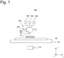
- FIG. 1 is a diagram schematically illustrating an AM apparatus for manufacturing a fabrication object according to one embodiment.
- an AM apparatus 100 includes a base plate 102.
- a fabrication object M is expected to be fabricated on the base plate 102.
- the base plate 102 can be a plate made from an arbitrary material capable of supporting the fabrication object M.
- the base plate 102 is disposed on an XY stage 104.
- the XY stage 104 is a stage 104 movable in two directions (an x direction and a y direction) perpendicular to each other in a horizontal plane.
- the XY stage 104 may be coupled with a lift mechanism movable in the height direction (a z direction). Further, in one embodiment, the XY stage 104 may be omitted.
- the AM apparatus 100 includes a DED head 200 as illustrated in Fig. 1 .
- the DED head 200 is connected to a laser source 202, a powder material source 300, and a gas source 206.
- the DED head 200 includes a DED nozzle 250.
- the DED nozzle 250 is configured to inject a laser, a powder material, and gas from the laser source 202, the powder material source 300, and the gas source 206, respectively.
- the DED head 200 can be an arbitrary DED head, and, for example, a known DED head can be used as it.
- the DED head 200 is coupled with a movement mechanism 220, and is movably configured.
- the movement mechanism 220 can be an arbitrary movement mechanism, and, for example, may be a movement mechanism capable of moving the DED head 200 along a specific axis such as a rail or may be formed from a robot capable of moving the DED head 200 to an arbitrary position and in an arbitrary direction.
- the movement mechanism 220 can be configured to be able to move the DED head 200 along perpendicular three axes.
- the AM apparatus 100 includes a control device 170 as illustrated in Fig. 1 .
- the control device 170 is configured to control the operations of various kinds of operation mechanisms of the AM apparatus 100, such as the above-described DED head 200 and various kinds of operation mechanisms 220.
- the control device 170 can be formed by a general computer or a dedicated computer.
- Fig. 2 is a diagram schematically illustrating a cross-section of the DED nozzle 250 according to one embodiment.
- the DED nozzle 250 according to the illustrated embodiment is a DED nozzle main body 259 having a generally truncated conical shape.
- the DED nozzle 250 according to the illustrated embodiment includes a first passage 252 at the center of the DED nozzle main body 259.
- a laser 251 passes through the first passage 252. After passing through the first passage 252, the laser is emitted from a laser port 252a of the DED nozzle main body 259.
- the DED nozzle main body 259 includes a second passage 254 outside the first passage 252.
- the powder material and carrier gas for transporting the powder material pass through the second passage 254.
- the DED nozzle main body 259 After passing through the second passage 254, the powder material is emitted from a powder port 254a. Further, the DED nozzle main body 259 includes a third passage 256 outside the second passage 254. Shield gas passes through the third passage 256. After passing through the third passage 256, the shield gas is emitted from a gas port 256a.
- the second passage 254 is configured in such a manner that the powder material discharged from the DED nozzle 250 is converged to substantially the same position as a focal point 251a of the laser 251.
- the flow of the powder material and the carrier gas is indicated by broken lines in Fig. 2 .
- the carrier gas can be inertial gas, such as argon gas or nitrogen gas. Argon gas heavier than air is further desirably used as the carrier gas. Using the inertial gas as the carrier gas allows a molten pool formed from the melted powder material to be covered with the inertial gas, thereby contributing to preventing oxidation thereof. However, due to the flow of the carrier gas emitted from the powder port 254a, air outside it may be entrained therein.
- the DED nozzle 250 illustrated in Fig. 2 can prevent surrounding air from being entrained by supplying the shield gas at a low speed from the third passage 256 provided outside the second passage 254, from which the powder material and the carrier gas are discharged. Preventing the surrounding air (especially, oxygen) from being entrained by the carrier gas can contribute to preventing a metal oxide film from being generated at the time of the fabrication, and, further, allow a highly wettable molten pool to be formed.
- the flow of the shield gas is indicated by arrows in Fig. 2 .
- the powder material should be supplied to the DED nozzle 250.
- the powder material source 300 is connected to the DED nozzle 250.
- Fig. 3 is a diagram schematically illustrating a powder supply apparatus 300 serving as the powder material source 300 according to one embodiment.
- the powder supply apparatus 300 includes a powder container 302 for storing the powder material 301 therein.
- a cover 350 is attached to the upper end of the powder container 302.
- the cover 350 may be configured detachably from the powder container 302.
- the powder supply apparatus 300 may be configured in such a manner that the powder material is replenished into the powder container 302 while the cover 350 is detached.
- the powder supply apparatus 300 may be configured in such a manner that the powder material can be replenished with the cover 350 kept attached to the powder container 302, as will be described below.
- the powder supply apparatus 300 includes a stirring device 310 disposed in the powder container 302, and is configured to be able to stir the powder material in the powder container 302.
- the lower end of the powder container 302 is connected to a weighing device 304.
- the weighing device 304 is further connected to a gas source 306.
- the gas source 306 can supply the carrier gas such as argon gas to the weighing device 304.
- the same gas source as the gas source 206 illustrated in Fig. 1 may be used as the gas source 306.
- the powder material supplied from the powder container 302 to the weighing device 304 is weighed, and is transmitted to the DED nozzle 250 together with the carrier gas.
- Fig. 4 is a cross-sectional view illustrating a structure of the cover 350 attached to the upper end of the powder container 302 according to one embodiment.
- Fig. 5 is a diagram illustrating the cover 350 illustrated in Fig. 4 as viewed from below.
- the cover 350 according to the illustrated embodiment is fixed to the upper end of the powder container 302 using a not-illustrated bolt or the like.
- the cover 350 includes a cover main body 352.
- the powder container 302 is an approximately cylindrical container, and the cover main body 352 has a generally disk-like shape.
- a supply port 354 is formed at the center of the cover main body 352, and a supply passage 356 is defined so as to extend through the cover main body 352 from the supply port 354.
- the cover 350 includes a valve structure 357 for opening and closing the supply passage 356 as illustrated in Fig. 4 .
- the valve structure 357 includes a valve main body 358.
- the valve main body 358 is rotationally movably supported using a pin 360.
- a first O-ring 362 is attached on the lower surface of the cover main body 352.
- a second O-ring 364 is attached outside the first O-ring 362 on the lower surface of the cover main body 352.
- Fig. 5 illustrates the cover 350 with the valve 357 omitted.
- the valve main body 358 is configured rotationally movably about the pin 360 between a first position, at which the upper surface thereof is in contact with the first O-ring 362 and the second O-ring 364, and a second position, at which the upper surface thereof is separated from the first O-ring 362 and the second O-ring 364.
- the supply passage 356 is closed by the valve main body 358.
- the valve main body 358 is located at the second position, the supply passage 356 is opened and the powder material can be loaded into the powder container 302 via the supply port 354 and the supply passage 356.
- the first O-ring 362 and the second O-ring 364 form a valve seat on which the valve main body 358 is seated.
- a portion of the valve main body 358 in contact with the first O-ring at the first position forms a first seal portion
- a portion of the valve main body 358 in contact with the second O-ring 364 at the first position forms a second seal portion.
- the first O-ring 362 forms a first seat portion
- the second O-ring 364 forms a second seat portion.
- the first O-ring 362 and the second O-ring 364 are provided on the lower surface of the cover main body 352 in the embodiment illustrated in Fig. 4 , but the powder supply apparatus 300 may be configured in such a manner that the first O-ring 362 and the second O-ring 364 are provided on the upper surface of the valve main body 358 as one embodiment.
- the powder supply apparatus 300 allows the powder material to be loaded from the supply port 354 and the supply passage 356 into the powder container 302 via the valve structure without requiring a removal of the cover 350.
- the powder material can be replenished into the powder container 302 by inserting, for example, a tube 390 for loading the powder material (refer to Fig. 6 and the like) into the supply port 354 and the supply passage 356.
- the powder material can be automatically supplied to the powder supply apparatus 300 by automatically and/or remotely operating the tube 390 for loading the powder material using a robot or the like. In the fabrication using the AM apparatus, humans may be prohibited from entering a fabrication chamber during the fabrication from a safety perspective.
- the powder supply apparatus 300 allows the powder material to be supplied to the powder supply apparatus 300 without manual intervention, therefore being also desirable in terms of safety.
- the valve structure 357 can include an elastic member 361, which biases the valve main body 358 toward the first position.
- the elastic member 361 can be a torsion spring such as the example illustrated in Figs. 4 and 6 .
- the torsion spring is disposed while being wound around the pin 360.
- the provision of the elastic member 361 leads to the valve main body 358 kept positioned at the first position where the valve main body 358 closes the supply passage 356 unless a force for opening the supply passage 356 is applied thereto. Therefore, the valve main body 358 is prevented from being opened accidentally and the powder material in the powder container 302 is prevented from being discharged from the supply passage 356.
- the powder material can be loaded into the powder container 302 by inserting the cylindrical tube 390 like the example illustrated in Fig. 6 from the supply port 354 into the supply passage 356 to move the valve main body 358 to the second position to open the supply passage 356, and supplying the powder material from the tube 390.
- the tube 390 allows the valve main body 358 to be rotationally moved from the first position to the second position by pushing down the valve main body 358, and the valve main body 358 can close the supply passage 356 by being automatically returned to the first position due to the function of the elastic member 361 when the tube 390 is pulled out.
- the valve 357 can be automatically opened by inserting the tube 390 into the supply passage 356, and the valve 357 can be automatically closed by extracting the tube 390 from the supply passage 356.
- a ring-shaped groove 366 is formed on the cover main body 352 between the first O-ring 362 and the second O-ring 364.
- an exhaust passage 368 which extends to a side surface of the cover main body 352, is formed in the ring-shaped groove 366.
- the exhaust passage 368 is connected to a vacuum pump 372.
- a pressure monitoring passage 370 which extends to an opposite side surface of the cover main body 352, is further formed in the ring-shaped groove 366.
- the pressure monitoring passage 370 is connected to a pressure gauze 374.
- a leak between the cover main body 352 and the first O-ring 362 and the second O-ring 364 can be detected by evacuating the ring-shaped groove 366 via the exhaust passage 368 and monitoring the pressure in the ring-shaped groove 366 via the pressure monitoring passage 370 when the valve main body 358 is disposed at the first position and the supply passage 356 is closed.
- whether the supply passage 356 can be securely closed by the valve main body 358 can be checked by monitoring the pressure in the ring-shaped groove 366 formed between the first O-ring 362 and the second O-ring 364.
- the powder material can be prevented from scattering around by controlling the powder supply apparatus 300 so as to start supplying the powder material therefrom only when the supply passage 356 can be securely closed by the valve main body 358.
- Fig. 7 is a cross-sectional view illustrating a structure of the cover 350 attached to the upper end of the powder container 302 according to one embodiment.
- the cover 350 according to the embodiment illustrated in Fig. 7 can be the same as the cover 350 illustrated in Fig. 4 except for the valve structure 357, which opens and closes the supply passage 356.
- the valve main body 358 is configured movably in a planar direction of the cover 350 and a direction perpendicular to the planar direction.
- the valve main body 358 is configured movably between a first position, at which the upper surface thereof is in contact with the first O-ring 362 and the second O-ring 364, and a second position, at which the upper surface thereof is separated from the first O-ring 362 and the second O-ring 364.
- the supply passage 356 is closed by the valve main body 358.
- the valve main body 358 is located at the second position, the supply passage 356 is opened and the powder material can be loaded into the powder container 302 via the supply port 354 and the supply passage 356.
- the first O-ring 362 and the second O-ring 364 are also provided on the lower surface of the cover main body 352 in the embodiment illustrated in Fig. 7 , but the powder supply apparatus 300 may be configured in such a manner that the first O-ring 362 and the second O-ring 364 are provided on the upper surface of the valve main body 358 as one embodiment.
- the embodiment illustrated in Fig. 7 can also achieve advantageous effects similar to the embodiments described with reference to Figs. 4 to 6 .
- Fig. 8 is a cross-sectional view illustrating a structure of the cover 350 attached to the upper end of the powder container 302 according to one embodiment.
- the cover 350 according to the embodiment illustrated in Fig. 8 is structured similarly to the cover 350 illustrated in Fig. 7 , but the ring-shaped groove 366, the exhaust passage 368, and the pressure monitoring passage 370 are not provided on the cover main body 352.
- a ring-shaped groove 394 is formed between a position of the valve main body 358 with which the first O-ring 362 (the first seat portion) is in contact (the first seal portion), and a position of the valve main body 358 with which the second O-ring 364 (the second seat portion) is in contact (the second seal portion).
- an exhaust passage 396 which extends to a side surface of the valve main body 358, is formed in the ring-shaped groove 394 formed on the valve main body 358.
- the exhaust passage 396 is connected to the vacuum pump 372.
- a pressure monitoring passage 398 which extends to the side surface of the valve main body 358, is further formed in the ring-shaped groove 394.
- the pressure monitoring passage 398 is connected to the pressure gauze 374.
- a leak between the valve main body 358 and the first O-ring 362 and the second O-ring 364 can be detected by evacuating the ring-shaped groove 394 via the exhaust passage 396 and monitoring the pressure in the ring-shaped groove 394 via the pressure monitoring passage 398 when the valve main body 358 is located at the first position and the supply passage 356 is closed.
- the first O-ring 362 and the second O-ring 364 are also provided on the lower surface of the cover main body 352 in the embodiment illustrated in Fig. 8 , but the powder supply apparatus 300 may be configured in such a manner that the first O-ring 362 and the second O-ring 364 are provided on the upper surface of the valve main body 358 as one embodiment.
- the embodiment illustrated in Fig. 8 can also achieve advantageous effects similar to the embodiments described with reference to Figs. 4 to 7 .
- Fig. 9 is a cross-sectional view schematically illustrating a structure around the supply passage 356 of the powder container 302 according to one embodiment.
- a first valve 330 for opening and closing a first position, and a second valve 332 for opening and closing a second position are provided in the supply passage 356 of the powder container 302.
- an exhaust line 334 for evacuation is connected to a space between the first position and the second position of the supply passage 356.
- the exhaust line 334 is connected to the vacuum pump 372.
- a pressure monitoring line 336 for monitoring the pressure is further connected to the space between the first position and the second position of the supply passage 356.
- the pressure monitoring passage 336 is connected to the pressure gauze 374.
- a leak from the first valve 330 and the second valve 332 can be checked by evacuating the space between the two valves via the exhaust line 334 and monitoring the pressure via the pressure monitoring line 336 when the first valve 330 and the second valve 332 are closed.
- the embodiment illustrated in Fig. 9 can also achieve advantageous effects similar to the embodiments described with reference to Figs. 4 to 8 .
- Fig. 10 is a flowchart illustrating a method for supplying a powder material from a powder supply apparatus according to one embodiment.
- the powder supply apparatus 300 according to an arbitrary one of the above-described embodiments or another arbitrary powder supply apparatus can be used as the powder supply apparatus.
- the valve is opened to load the powder material into the powder supply apparatus (S100).
- the valve of the powder supply apparatus 300 can be opened by inserting the tube 390 into the supply passage 356 via the supply port 354 to thus rotate the valve main body 358. It is desirable to insert the tube 390 by an automatic operation and/or a remote operation using a robot or the like.
- the supply passage 356 can be opened by moving the valve main body 358 downward and laterally.
- the supply passage 356 can be opened by opening both the first valve 330 and the second valve 332. It is also desirable to open the valve without manual intervention with the aid of an electric or electromagnetic effect in the powder supply apparatuses 300 illustrated in Figs. 7 to 9 .
- the powder material is loaded into the powder container 302 of the powder supply apparatus 300 (S 102).
- the powder material is loaded by, for example, inserting the tube 390 and supplying the powder material into the powder container 302 via inside the tube 390.
- the powder material is loaded into the powder container 302
- the valve of the powder supply apparatus 300 is closed (S104).
- the valve main body 358 automatically closes the supply passage 356 when the tube 390 is pulled out from the supply passage 356.
- the supply passage 356 is closed by moving the valve main body 358 to the first position after pulling out the tube 390 from the supply passage 356.
- the supply passage 356 can be closed by closing both the first valve 330 and the second valve 332.
- the ring-shaped groove 366 or 394 is evacuated via the exhaust passage 368 or 396, and the pressure in the ring-shaped groove 366 or 394 is measured via the pressure monitoring passage 370 or 398. If the pressure in the ring-shaped groove 366 or 394 is sufficiently low, the powder supply apparatus 300 is determined to be sealed appropriately by the valve main body 358 and the O-rings 362 and 364.
- the powder supply apparatus 300 is determined not to be sealed appropriately by the valve main body 358 and the O-rings 362 and 364. If being not sealed appropriately, the powder supply apparatus 300 should be subjected to maintenance such as cleaning of the valve mechanism or a replacement of a component.
- the powder material is supplied from the powder supply apparatus 300 to an intended location.
- the powder material can be supplied from the powder supply apparatus 300 to the DED nozzle 250 of the AM apparatus 100.
- the method according to the above-described embodiment includes confirming whether the valve is closed before supplying the powder material to the intended location, thereby being able to prevent the powder material from leaking out from the supply passage 356 or the like during the supply of the powder material.
Landscapes
- Engineering & Computer Science (AREA)
- Mechanical Engineering (AREA)
- Physics & Mathematics (AREA)
- Optics & Photonics (AREA)
- Chemical & Material Sciences (AREA)
- Materials Engineering (AREA)
- Manufacturing & Machinery (AREA)
- Plasma & Fusion (AREA)
- Filling Or Emptying Of Bunkers, Hoppers, And Tanks (AREA)
- Laser Beam Processing (AREA)
- Powder Metallurgy (AREA)
Abstract
Description
- The present application relates to a powder supply apparatus and an AM apparatus using a powder supply apparatus. The present application claims priority under the Paris Convention to
Japanese Patent Application No. 2020-169369 filed on October 6, 2020 Japanese Patent Application No. 2020-169369 - There are known techniques for directly fabricating a three-dimensional object based on three-dimensional data present on a computer that expresses the three-dimensional object. Known examples thereof include the Additive Manufacturing (AM) technique. As one example thereof, Direct Energy Deposition (DED) is available as the AM technique employing the deposition method. DED is a technique that carries out fabrication by melting and solidifying a powdered metal material together with a base material using an appropriate heat source while supplying the powdered metal material locally.
- In the case where the three-dimensional object is fabricated by DED, the fabrication is carried out in such a manner that the powder material is melted and solidified by being irradiated with a laser while being supplied to a fabrication position using a DED nozzle. Therefore, in the case where the three-dimensional object is fabricated by DED, the powder material should be kept supplied to the DED nozzle. Generally, the supply of the powder material to the DED nozzle is conducted by supplying the powder material to the DED nozzle together with carrier gas using a powder supply apparatus. The powder supply apparatus can store the powder material therein and supply the powder material to a supply destination such as the DED nozzle by a predetermined supply amount.
- PTL 1:
Japanese Patent Application Public Disclosure No. 2005-219060 - When a large three-dimensional object is fabricated by DED, the fabrication may be unable to be completed using only the powder material prestored in the powder supply apparatus, and therefore the powder material should be replenished into the powder supply apparatus in the middle of the fabrication. The powder material is often replenished into the powder supply apparatus manually because this work necessitates detachment of a component or the like. This means that the fabrication by DED is temporarily interrupted and a longer time is required for the fabrication to replenish the powder material into the powder supply apparatus. In light thereof, it is desirable to allow the powder material to be supplied to the powder supply apparatus not manually but automatically. Further, automatically supplying the powder material to the powder supply apparatus can contribute to reducing a risk that a human inhales the powder material. Further, when the powder material is supplied to the supply destination such as the DED nozzle using the powder supply apparatus together with the carrier gas, a container storing the powder material therein in the powder supply apparatus may be pressurized. Therefore, the powder material may scatter around from the container unless the container storing the powder material therein is appropriately sealed. In light thereof, it is desirable to appropriately seal the container storing the powder material therein. One of objects of the present application is to provide a structure capable of solving or alleviating at least a part of these problems.
- According to one aspect, a powder supply apparatus is provided. The powder supply apparatus includes a container configured to store powder therein, a supply passage configured to supply the powder to the container therethrough, and a valve mechanism configured to open and close the supply passage thereby. The valve mechanism includes a valve main body movable between a first position, at which the valve main body closes the supply passage, and a second position, at which the valve main body opens the supply passage, and further includes a valve seat configured in such a manner that the valve main body is seated thereon. The valve main body includes a first seal portion and a second seal portion. The valve seat includes a first seat portion on which the first seal portion is seated, and a second seat portion on which the second seal portion is seated. The valve mechanism defines a space sealingly closed when the first seal portion is seated on the first seat portion and the second seal portion is seated on the second seat portion. The valve mechanism includes an exhaust passage configured to exhaust gas from the sealingly closed space therethrough and a pressure monitoring passage configured to be used to monitor a pressure in the sealingly closed space.
-
-
Fig. 1 is a diagram schematically illustrating an AM apparatus for manufacturing a fabrication object according to one embodiment. -
Fig. 2 is a diagram schematically illustrating a cross-section of a DED nozzle according to one embodiment. -
Fig. 3 is a diagram schematically illustrating a powder supply apparatus serving as a powder material source according to one embodiment. -
Fig. 4 is a cross-sectional view schematically illustrating a structure of a cover attached to the upper end of a powder container according to one embodiment. -
Fig. 5 is a diagram illustrating the cover illustrated inFig. 4 as viewed from below. -
Fig. 6 is a diagram illustrating a supply passage of the cover illustrated inFig. 4 in an opened state. -
Fig. 7 is a cross-sectional view schematically illustrating a structure of the cover attached to the upper end of the powder container according to one embodiment. -
Fig. 8 is a cross-sectional view schematically illustrating a structure of the cover attached to the upper end of the powder container according to one embodiment. -
Fig. 9 is a cross-sectional view schematically illustrating a structure around the supply passage of the powder container according to one embodiment. -
Fig. 10 is a flowchart illustrating a method for supplying a powder material from a powder supply apparatus according to one embodiment. - In the following description, embodiments of a powder supply apparatus and an AM apparatus using a powder supply apparatus according to the present invention will be described with reference to the attached drawings. In the attached drawings, identical or similar components will be indicated by identical or similar reference numerals, and redundant descriptions regarding the identical or similar components may be omitted in the description of each of the embodiments. Further, features described in each of the embodiments are also applicable to other embodiments in so far as they do not contradict each other.
-
Fig. 1 is a diagram schematically illustrating an AM apparatus for manufacturing a fabrication object according to one embodiment. As illustrated inFig. 1 , anAM apparatus 100 includes abase plate 102. A fabrication object M is expected to be fabricated on thebase plate 102. Thebase plate 102 can be a plate made from an arbitrary material capable of supporting the fabrication object M. In one embodiment, thebase plate 102 is disposed on anXY stage 104. TheXY stage 104 is astage 104 movable in two directions (an x direction and a y direction) perpendicular to each other in a horizontal plane. TheXY stage 104 may be coupled with a lift mechanism movable in the height direction (a z direction). Further, in one embodiment, theXY stage 104 may be omitted. - In one embodiment, the
AM apparatus 100 includes aDED head 200 as illustrated inFig. 1 . The DEDhead 200 is connected to alaser source 202, apowder material source 300, and agas source 206. The DEDhead 200 includes aDED nozzle 250. The DEDnozzle 250 is configured to inject a laser, a powder material, and gas from thelaser source 202, thepowder material source 300, and thegas source 206, respectively. - The
DED head 200 can be an arbitrary DED head, and, for example, a known DED head can be used as it. TheDED head 200 is coupled with amovement mechanism 220, and is movably configured. Themovement mechanism 220 can be an arbitrary movement mechanism, and, for example, may be a movement mechanism capable of moving theDED head 200 along a specific axis such as a rail or may be formed from a robot capable of moving theDED head 200 to an arbitrary position and in an arbitrary direction. As one embodiment, themovement mechanism 220 can be configured to be able to move theDED head 200 along perpendicular three axes. - The
AM apparatus 100 according to one embodiment includes acontrol device 170 as illustrated inFig. 1 . Thecontrol device 170 is configured to control the operations of various kinds of operation mechanisms of theAM apparatus 100, such as the above-describedDED head 200 and various kinds ofoperation mechanisms 220. Thecontrol device 170 can be formed by a general computer or a dedicated computer. -
Fig. 2 is a diagram schematically illustrating a cross-section of theDED nozzle 250 according to one embodiment. TheDED nozzle 250 according to the illustrated embodiment is a DED nozzlemain body 259 having a generally truncated conical shape. TheDED nozzle 250 according to the illustrated embodiment includes afirst passage 252 at the center of the DED nozzlemain body 259. Alaser 251 passes through thefirst passage 252. After passing through thefirst passage 252, the laser is emitted from alaser port 252a of the DED nozzlemain body 259. Further, the DED nozzlemain body 259 includes asecond passage 254 outside thefirst passage 252. The powder material and carrier gas for transporting the powder material pass through thesecond passage 254. After passing through thesecond passage 254, the powder material is emitted from apowder port 254a. Further, the DED nozzlemain body 259 includes athird passage 256 outside thesecond passage 254. Shield gas passes through thethird passage 256. After passing through thethird passage 256, the shield gas is emitted from agas port 256a. - The
second passage 254 is configured in such a manner that the powder material discharged from theDED nozzle 250 is converged to substantially the same position as afocal point 251a of thelaser 251. The flow of the powder material and the carrier gas is indicated by broken lines inFig. 2 . The carrier gas can be inertial gas, such as argon gas or nitrogen gas. Argon gas heavier than air is further desirably used as the carrier gas. Using the inertial gas as the carrier gas allows a molten pool formed from the melted powder material to be covered with the inertial gas, thereby contributing to preventing oxidation thereof. However, due to the flow of the carrier gas emitted from thepowder port 254a, air outside it may be entrained therein. In light thereof, theDED nozzle 250 illustrated inFig. 2 can prevent surrounding air from being entrained by supplying the shield gas at a low speed from thethird passage 256 provided outside thesecond passage 254, from which the powder material and the carrier gas are discharged. Preventing the surrounding air (especially, oxygen) from being entrained by the carrier gas can contribute to preventing a metal oxide film from being generated at the time of the fabrication, and, further, allow a highly wettable molten pool to be formed. The flow of the shield gas is indicated by arrows inFig. 2 . - In the case where the fabrication is carried out using the
DED nozzle 250 as described above, the powder material should be supplied to theDED nozzle 250. As illustrated inFig. 1 , thepowder material source 300 is connected to theDED nozzle 250.Fig. 3 is a diagram schematically illustrating apowder supply apparatus 300 serving as thepowder material source 300 according to one embodiment. - As illustrated in
Fig. 3 , thepowder supply apparatus 300 includes apowder container 302 for storing thepowder material 301 therein. Acover 350 is attached to the upper end of thepowder container 302. Thecover 350 may be configured detachably from thepowder container 302. In the case where thecover 350 is configured detachably from thepowder container 302, thepowder supply apparatus 300 may be configured in such a manner that the powder material is replenished into thepowder container 302 while thecover 350 is detached. Alternatively, in one embodiment, thepowder supply apparatus 300 may be configured in such a manner that the powder material can be replenished with thecover 350 kept attached to thepowder container 302, as will be described below. In one embodiment, thepowder supply apparatus 300 includes astirring device 310 disposed in thepowder container 302, and is configured to be able to stir the powder material in thepowder container 302. - The lower end of the
powder container 302 is connected to a weighingdevice 304. The weighingdevice 304 is further connected to agas source 306. Thegas source 306 can supply the carrier gas such as argon gas to the weighingdevice 304. The same gas source as thegas source 206 illustrated inFig. 1 may be used as thegas source 306. The powder material supplied from thepowder container 302 to the weighingdevice 304 is weighed, and is transmitted to theDED nozzle 250 together with the carrier gas. -
Fig. 4 is a cross-sectional view illustrating a structure of thecover 350 attached to the upper end of thepowder container 302 according to one embodiment.Fig. 5 is a diagram illustrating thecover 350 illustrated inFig. 4 as viewed from below. Thecover 350 according to the illustrated embodiment is fixed to the upper end of thepowder container 302 using a not-illustrated bolt or the like. Thecover 350 includes a covermain body 352. In one embodiment, thepowder container 302 is an approximately cylindrical container, and the covermain body 352 has a generally disk-like shape. Asupply port 354 is formed at the center of the covermain body 352, and asupply passage 356 is defined so as to extend through the covermain body 352 from thesupply port 354. - In one embodiment, the
cover 350 includes avalve structure 357 for opening and closing thesupply passage 356 as illustrated inFig. 4 . Thevalve structure 357 includes a valvemain body 358. The valvemain body 358 is rotationally movably supported using apin 360. A first O-ring 362 is attached on the lower surface of the covermain body 352. Further, a second O-ring 364 is attached outside the first O-ring 362 on the lower surface of the covermain body 352.Fig. 5 illustrates thecover 350 with thevalve 357 omitted. - The valve
main body 358 is configured rotationally movably about thepin 360 between a first position, at which the upper surface thereof is in contact with the first O-ring 362 and the second O-ring 364, and a second position, at which the upper surface thereof is separated from the first O-ring 362 and the second O-ring 364. When the valvemain body 358 is located at the first position, thesupply passage 356 is closed by the valvemain body 358. On the other hand, when the valvemain body 358 is located at the second position, thesupply passage 356 is opened and the powder material can be loaded into thepowder container 302 via thesupply port 354 and thesupply passage 356. In the embodiment illustrated inFig. 4 , the first O-ring 362 and the second O-ring 364 form a valve seat on which the valvemain body 358 is seated. A portion of the valvemain body 358 in contact with the first O-ring at the first position forms a first seal portion, and a portion of the valvemain body 358 in contact with the second O-ring 364 at the first position forms a second seal portion. Further, the first O-ring 362 forms a first seat portion, and the second O-ring 364 forms a second seat portion. The first O-ring 362 and the second O-ring 364 are provided on the lower surface of the covermain body 352 in the embodiment illustrated inFig. 4 , but thepowder supply apparatus 300 may be configured in such a manner that the first O-ring 362 and the second O-ring 364 are provided on the upper surface of the valvemain body 358 as one embodiment. - The
powder supply apparatus 300 according to this embodiment allows the powder material to be loaded from thesupply port 354 and thesupply passage 356 into thepowder container 302 via the valve structure without requiring a removal of thecover 350. For example, the powder material can be replenished into thepowder container 302 by inserting, for example, atube 390 for loading the powder material (refer toFig. 6 and the like) into thesupply port 354 and thesupply passage 356. The powder material can be automatically supplied to thepowder supply apparatus 300 by automatically and/or remotely operating thetube 390 for loading the powder material using a robot or the like. In the fabrication using the AM apparatus, humans may be prohibited from entering a fabrication chamber during the fabrication from a safety perspective. Therefore, if the powder material can be replenished into thepowder supply apparatus 300 not manually but automatically, the powder material can be replenished into thepowder supply apparatus 300 without interrupting the fabrication, and the efficiency increases. Further, thepowder supply apparatus 300 according to this embodiment allows the powder material to be supplied to thepowder supply apparatus 300 without manual intervention, therefore being also desirable in terms of safety. - In one embodiment, the
valve structure 357 can include anelastic member 361, which biases the valvemain body 358 toward the first position. In one embodiment, theelastic member 361 can be a torsion spring such as the example illustrated inFigs. 4 and6 . The torsion spring is disposed while being wound around thepin 360. The provision of theelastic member 361 leads to the valvemain body 358 kept positioned at the first position where the valvemain body 358 closes thesupply passage 356 unless a force for opening thesupply passage 356 is applied thereto. Therefore, the valvemain body 358 is prevented from being opened accidentally and the powder material in thepowder container 302 is prevented from being discharged from thesupply passage 356. When the powder material is loaded into thepowder container 302, the powder material can be loaded into thepowder container 302 by inserting thecylindrical tube 390 like the example illustrated inFig. 6 from thesupply port 354 into thesupply passage 356 to move the valvemain body 358 to the second position to open thesupply passage 356, and supplying the powder material from thetube 390. In the case where theelastic member 361 is used, thetube 390 allows the valvemain body 358 to be rotationally moved from the first position to the second position by pushing down the valvemain body 358, and the valvemain body 358 can close thesupply passage 356 by being automatically returned to the first position due to the function of theelastic member 361 when thetube 390 is pulled out. According to this embodiment, thevalve 357 can be automatically opened by inserting thetube 390 into thesupply passage 356, and thevalve 357 can be automatically closed by extracting thetube 390 from thesupply passage 356. - As illustrated in
Fig. 4 , a ring-shapedgroove 366 is formed on the covermain body 352 between the first O-ring 362 and the second O-ring 364. As illustrated inFig. 4 , anexhaust passage 368, which extends to a side surface of the covermain body 352, is formed in the ring-shapedgroove 366. Theexhaust passage 368 is connected to avacuum pump 372. Further, apressure monitoring passage 370, which extends to an opposite side surface of the covermain body 352, is further formed in the ring-shapedgroove 366. Thepressure monitoring passage 370 is connected to apressure gauze 374. A leak between the covermain body 352 and the first O-ring 362 and the second O-ring 364 can be detected by evacuating the ring-shapedgroove 366 via theexhaust passage 368 and monitoring the pressure in the ring-shapedgroove 366 via thepressure monitoring passage 370 when the valvemain body 358 is disposed at the first position and thesupply passage 356 is closed. - In the above-described embodiment, whether the
supply passage 356 can be securely closed by the valvemain body 358 can be checked by monitoring the pressure in the ring-shapedgroove 366 formed between the first O-ring 362 and the second O-ring 364. The powder material can be prevented from scattering around by controlling thepowder supply apparatus 300 so as to start supplying the powder material therefrom only when thesupply passage 356 can be securely closed by the valvemain body 358. -
Fig. 7 is a cross-sectional view illustrating a structure of thecover 350 attached to the upper end of thepowder container 302 according to one embodiment. Thecover 350 according to the embodiment illustrated inFig. 7 can be the same as thecover 350 illustrated inFig. 4 except for thevalve structure 357, which opens and closes thesupply passage 356. In thevalve structure 357 according to the embodiment illustrated inFig. 7 , the valvemain body 358 is configured movably in a planar direction of thecover 350 and a direction perpendicular to the planar direction. In the embodiment illustrated inFig. 7 , the valvemain body 358 is configured movably between a first position, at which the upper surface thereof is in contact with the first O-ring 362 and the second O-ring 364, and a second position, at which the upper surface thereof is separated from the first O-ring 362 and the second O-ring 364. When the valvemain body 358 is located at the first position, thesupply passage 356 is closed by the valvemain body 358. On the other hand, when the valvemain body 358 is located at the second position, thesupply passage 356 is opened and the powder material can be loaded into thepowder container 302 via thesupply port 354 and thesupply passage 356. The first O-ring 362 and the second O-ring 364 are also provided on the lower surface of the covermain body 352 in the embodiment illustrated inFig. 7 , but thepowder supply apparatus 300 may be configured in such a manner that the first O-ring 362 and the second O-ring 364 are provided on the upper surface of the valvemain body 358 as one embodiment. The embodiment illustrated inFig. 7 can also achieve advantageous effects similar to the embodiments described with reference toFigs. 4 to 6 . -
Fig. 8 is a cross-sectional view illustrating a structure of thecover 350 attached to the upper end of thepowder container 302 according to one embodiment. Thecover 350 according to the embodiment illustrated inFig. 8 is structured similarly to thecover 350 illustrated inFig. 7 , but the ring-shapedgroove 366, theexhaust passage 368, and thepressure monitoring passage 370 are not provided on the covermain body 352. In the embodiment illustrated inFig. 8 , a ring-shapedgroove 394 is formed between a position of the valvemain body 358 with which the first O-ring 362 (the first seat portion) is in contact (the first seal portion), and a position of the valvemain body 358 with which the second O-ring 364 (the second seat portion) is in contact (the second seal portion). As illustrated inFig. 8 , anexhaust passage 396, which extends to a side surface of the valvemain body 358, is formed in the ring-shapedgroove 394 formed on the valvemain body 358. Theexhaust passage 396 is connected to thevacuum pump 372. Further, apressure monitoring passage 398, which extends to the side surface of the valvemain body 358, is further formed in the ring-shapedgroove 394. Thepressure monitoring passage 398 is connected to thepressure gauze 374. A leak between the valvemain body 358 and the first O-ring 362 and the second O-ring 364 can be detected by evacuating the ring-shapedgroove 394 via theexhaust passage 396 and monitoring the pressure in the ring-shapedgroove 394 via thepressure monitoring passage 398 when the valvemain body 358 is located at the first position and thesupply passage 356 is closed. The first O-ring 362 and the second O-ring 364 are also provided on the lower surface of the covermain body 352 in the embodiment illustrated inFig. 8 , but thepowder supply apparatus 300 may be configured in such a manner that the first O-ring 362 and the second O-ring 364 are provided on the upper surface of the valvemain body 358 as one embodiment. The embodiment illustrated inFig. 8 can also achieve advantageous effects similar to the embodiments described with reference toFigs. 4 to 7 . -
Fig. 9 is a cross-sectional view schematically illustrating a structure around thesupply passage 356 of thepowder container 302 according to one embodiment. In the embodiment illustrated inFig. 9 , afirst valve 330 for opening and closing a first position, and asecond valve 332 for opening and closing a second position are provided in thesupply passage 356 of thepowder container 302. In the embodiment illustrated inFig. 9 , anexhaust line 334 for evacuation is connected to a space between the first position and the second position of thesupply passage 356. Theexhaust line 334 is connected to thevacuum pump 372. Further, apressure monitoring line 336 for monitoring the pressure is further connected to the space between the first position and the second position of thesupply passage 356. Thepressure monitoring passage 336 is connected to thepressure gauze 374. A leak from thefirst valve 330 and thesecond valve 332 can be checked by evacuating the space between the two valves via theexhaust line 334 and monitoring the pressure via thepressure monitoring line 336 when thefirst valve 330 and thesecond valve 332 are closed. The embodiment illustrated inFig. 9 can also achieve advantageous effects similar to the embodiments described with reference toFigs. 4 to 8 . -
Fig. 10 is a flowchart illustrating a method for supplying a powder material from a powder supply apparatus according to one embodiment. In the embodiment illustrated inFig. 10 , thepowder supply apparatus 300 according to an arbitrary one of the above-described embodiments or another arbitrary powder supply apparatus can be used as the powder supply apparatus. - In the method for supplying the powder material according to one embodiment, first, the valve is opened to load the powder material into the powder supply apparatus (S100). In the case of the
powder supply apparatus 300 according to the embodiments illustrated inFigs. 4 to 6 , the valve of thepowder supply apparatus 300 can be opened by inserting thetube 390 into thesupply passage 356 via thesupply port 354 to thus rotate the valvemain body 358. It is desirable to insert thetube 390 by an automatic operation and/or a remote operation using a robot or the like. In the case of thepowder supply apparatus 300 according to the embodiments illustrated inFigs. 7 and8 , thesupply passage 356 can be opened by moving the valvemain body 358 downward and laterally. In the case of thepowder supply apparatus 300 according to the embodiment illustrated inFig. 9 , thesupply passage 356 can be opened by opening both thefirst valve 330 and thesecond valve 332. It is also desirable to open the valve without manual intervention with the aid of an electric or electromagnetic effect in thepowder supply apparatuses 300 illustrated inFigs. 7 to 9 . - After the valve is opened, the powder material is loaded into the
powder container 302 of the powder supply apparatus 300 (S 102). The powder material is loaded by, for example, inserting thetube 390 and supplying the powder material into thepowder container 302 via inside thetube 390. When the powder material is loaded into thepowder container 302, it is desirable to prevent the powder from being attached to the seal portions on the upper surface of the valvemain body 358 and the seat portions such as the O-rings. Therefore, in the case where the powder material is supplied by inserting thetube 390, it is desirable to supply the powder material into thepowder container 302 after creating such a state that the lower end of thetube 390 is located on the lower side with respect to the valvemain body 358. - After the powder material is loaded into the
powder container 302, the valve of thepowder supply apparatus 300 is closed (S104). In the case where theelastic member 361 is provided like the embodiments illustrated inFigs. 4 to 6 , the valvemain body 358 automatically closes thesupply passage 356 when thetube 390 is pulled out from thesupply passage 356. In the case of thepowder supply apparatus 300 according to the embodiments illustrated inFigs. 7 and8 , thesupply passage 356 is closed by moving the valvemain body 358 to the first position after pulling out thetube 390 from thesupply passage 356. In the case of thepowder supply apparatus 300 according to the embodiment illustrated inFig. 9 , thesupply passage 356 can be closed by closing both thefirst valve 330 and thesecond valve 332. - After the valve of the
powder supply apparatus 300 is closed, whether the valve is closed is confirmed (S 106). In the case of thepowder supply apparatus 300 according to the embodiments illustrated inFigs. 4 to 8 , the ring-shapedgroove exhaust passage groove pressure monitoring passage groove powder supply apparatus 300 is determined to be sealed appropriately by the valvemain body 358 and the O-rings groove powder supply apparatus 300 is determined not to be sealed appropriately by the valvemain body 358 and the O-rings powder supply apparatus 300 should be subjected to maintenance such as cleaning of the valve mechanism or a replacement of a component. - After the closing of the valve is confirmed, the powder material is supplied from the
powder supply apparatus 300 to an intended location. For example, the powder material can be supplied from thepowder supply apparatus 300 to theDED nozzle 250 of theAM apparatus 100. - The method according to the above-described embodiment includes confirming whether the valve is closed before supplying the powder material to the intended location, thereby being able to prevent the powder material from leaking out from the
supply passage 356 or the like during the supply of the powder material. - At least the following technical ideas can be recognized from the above-described embodiments.
- [Configuration 1] According to a configuration 1, a powder supply apparatus is provided. The powder supply apparatus includes a container configured to store powder therein, a supply passage configured to supply the powder to the container therethrough, and a valve mechanism configured to open and close the supply passage thereby. The valve mechanism includes a valve main body movable between a first position, at which the valve main body closes the supply passage, and a second position, at which the valve main body opens the supply passage, and further includes a valve seat configured in such a manner that the valve main body is seated thereon. The valve main body includes a first seal portion and a second seal portion. The valve seat includes a first seat portion on which the first seal portion is seated, and a second seat portion on which the second seal portion is seated. The valve mechanism defines a space sealingly closed when the first seal portion is seated on the first seat portion and the second seal portion is seated on the second seat portion. The valve mechanism includes an exhaust passage configured to exhaust gas from the sealingly closed space therethrough and a pressure monitoring passage configured to be used to monitor a pressure in the sealingly closed space.
- [Configuration 2] According to a configuration 2, in the powder supply apparatus according to the configuration 1, the supply passage is configured to be able to allow a tube for supplying the powder to the container to be inserted therein.
- [Configuration 3] According to a configuration 3, in the powder supply apparatus according to the configuration 1 or 2, the first seat portion includes a first O-ring and the second seat portion includes a second O-ring.
- [Configuration 4] According to a configuration 4, in the powder supply apparatus according to any one of the configurations 1 to 3, the valve main body is supported using a pin rotationally movably between the first position, at which the valve main body closes the supply passage, and the second position, at which the valve main body opens the supply passage.
- [Configuration 5] According to a configuration 5, the powder supply apparatus according to the configuration 4 further includes an elastic member configured to bias the valve main body toward the first position.
- [Configuration 6] According to a configuration 6, a powder supply apparatus is provided. The power supply apparatus includes a container configured to store powder therein, a supply passage configured to supply the powder to the container therethrough, a first valve configured to open and close a first position of the supply passage thereby, a second valve configured to open and close a second position of the supply passage thereby, an exhaust passage configured to exhaust gas therethrough from a space between the first position and the second position of the supply passage, and a pressure measurement passage configured to be used to measure a pressure in the space between the first position and the second position of the supply passage.
- [Configuration 7] According to a configuration 7, a method for supplying a powder material from a powder supply apparatus is provided. The powder supply apparatus includes a container configured to store powder therein, a supply passage configured to supply the powder to the container therethrough, and a valve configured to open and close the supply passage thereby. The method includes steps of opening the valve, loading the powder material into the container via the supply passage, closing the valve, confirming whether the valve is closed, and supplying the powder material from the powder supply apparatus after confirming that the valve is closed.
- [Configuration 8] According to a configuration 8, an AM apparatus configured to manufacture a fabrication object is provided. The AM apparatus includes a DED nozzle. The DED nozzle includes a laser port provided at a distal end of the DED nozzle and configured to emit laser light therefrom, a laser passage provided in communication with the laser port and configured to allow the laser light to pass through inside the DED nozzle, a powder port provided at the distal end of the DED nozzle and configured to inject a powder material therefrom, and a powder passage provided in communication with the powder port and configured to allow the powder material to pass through inside the DED nozzle. The AM apparatus further includes the powder supply apparatus configured to supply the powder material to the DED nozzle according to any one of the configurations 1 to 6.
-
- 100
- AM apparatus
- 300
- powder supply apparatus
- 301
- powder material
- 302
- powder container
- 304
- weighing device
- 306
- gas source
- 310
- stirring device
- 330
- first valve
- 332
- second valve
- 334
- exhaust line
- 336
- pressure monitoring line
- 350
- cover
- 352
- cover main body
- 354
- supply port
- 356
- supply passage
- 357
- valve mechanism
- 358
- valve main body
- 360
- pin
- 362
- first O-ring
- 364
- second O-ring
- 366
- ring-shaped groove
- 368
- exhaust passage
- 370
- pressure monitoring passage
- 372
- vacuum pump
- 374
- pressure gauge
- 390
- tube
- 394
- ring-shaped groove
- 396
- exhaust passage
- 398
- pressure monitoring passage
Claims (8)
- A powder supply apparatus comprising:a container configured to store powder therein;a supply passage configured to supply the powder to the container therethrough; anda valve mechanism configured to open and close the supply passage thereby,wherein the valve mechanism includes a valve main body movable between a first position, at which the valve main body closes the supply passage, and a second position, at which the valve main body opens the supply passage, and further includes a valve seat configured in such a manner that the valve main body is seated thereon,wherein the valve main body includes a first seal portion and a second seal portion,wherein the valve seat includes a first seat portion on which the first seal portion is seated, and a second seat portion on which the second seal portion is seated,wherein the valve mechanism defines a space sealingly closed when the first seal portion is seated on the first seat portion and the second seal portion is seated on the second seat portion, andwherein the valve mechanism includes an exhaust passage configured to exhaust gas from the sealingly closed space therethrough and a pressure monitoring passage configured to be used to monitor a pressure in the sealingly closed space.
- The powder supply apparatus according to claim 1, wherein the supply passage is configured to be able to allow a tube for supplying the powder to the container to be inserted therein.
- The powder supply apparatus according to claim 1 or 2, wherein the first seat portion includes a first O-ring and the second seat portion includes a second O-ring.
- The powder supply apparatus according to any one of claims 1 to 3, wherein the valve main body is supported using a pin rotationally movably between the first position, at which the valve main body closes the supply passage, and the second position, at which the valve main body opens the supply passage.
- The powder supply apparatus according to claim 4, further comprising an elastic member configured to bias the valve main body toward the first position.
- A powder supply apparatus comprising:a container configured to store powder therein;a supply passage configured to supply the powder to the container therethrough;a first valve configured to open and close a first position of the supply passage thereby;a second valve configured to open and close a second position of the supply passage thereby;an exhaust passage configured to exhaust gas therethrough from a space between the first position and the second position of the supply passage; anda pressure measurement passage configured to be used to measure a pressure in the space between the first position and the second position of the supply passage.
- A method for supplying a powder material from a powder supply apparatus,
the powder supply apparatus includinga container configured to store powder therein,a supply passage configured to supply the powder to the container therethrough, anda valve configured to open and close the supply passage thereby,the method comprising steps of:opening the valve;loading the powder material into the container via the supply passage;closing the valve;confirming whether the valve is closed; andsupplying the powder material from the powder supply apparatus after confirming that the valve is closed. - An AM apparatus configured to manufacture a fabrication object, the AM apparatus comprising:a DED nozzle, the DED nozzle includinga laser port provided at a distal end of the DED nozzle and configured to emit laser light therefrom, and a laser passage provided in communication with the laser port and configured to allow the laser light to pass through inside the DED nozzle, anda powder port provided at the distal end of the DED nozzle and configured to inject a powder material therefrom, and a powder passage provided in communication with the powder port and configured to allow the powder material to pass through inside the DED nozzle;the AM apparatus further comprising the powder supply apparatus configured to supply the powder material to the DED nozzle according to any one of claims 1 to 6.
Applications Claiming Priority (2)
| Application Number | Priority Date | Filing Date | Title |
|---|---|---|---|
| JP2020169369A JP7597545B2 (en) | 2020-10-06 | 2020-10-06 | Powder supply device and AM device using the powder supply device |
| PCT/JP2021/033678 WO2022075013A1 (en) | 2020-10-06 | 2021-09-14 | Powder supply device, and am device using powder supply device |
Publications (2)
| Publication Number | Publication Date |
|---|---|
| EP4227225A1 true EP4227225A1 (en) | 2023-08-16 |
| EP4227225A4 EP4227225A4 (en) | 2025-01-22 |
Family
ID=81126810
Family Applications (1)
| Application Number | Title | Priority Date | Filing Date |
|---|---|---|---|
| EP21877316.6A Pending EP4227225A4 (en) | 2020-10-06 | 2021-09-14 | Powder supply device, and am device using powder supply device |
Country Status (5)
| Country | Link |
|---|---|
| US (1) | US12623291B2 (en) |
| EP (1) | EP4227225A4 (en) |
| JP (1) | JP7597545B2 (en) |
| CN (1) | CN116323395B (en) |
| WO (1) | WO2022075013A1 (en) |
Cited By (1)
| Publication number | Priority date | Publication date | Assignee | Title |
|---|---|---|---|---|
| EP4309896A4 (en) * | 2021-03-19 | 2025-05-21 | Ebara Corporation | ADDITIVE MANUFACTURING (AM) DEVICE |
Families Citing this family (2)
| Publication number | Priority date | Publication date | Assignee | Title |
|---|---|---|---|---|
| JP2024089766A (en) * | 2022-12-22 | 2024-07-04 | 株式会社荏原製作所 | Powder Supply Device |
| WO2026094215A1 (en) * | 2024-10-31 | 2026-05-07 | 株式会社ニコン | Fabrication system and material supply member |
Family Cites Families (18)
| Publication number | Priority date | Publication date | Assignee | Title |
|---|---|---|---|---|
| US5876550A (en) * | 1988-10-05 | 1999-03-02 | Helisys, Inc. | Laminated object manufacturing apparatus and method |
| DE9212623U1 (en) * | 1992-09-18 | 1993-08-05 | Alfred Bolz Gmbh & Co Kg, 88239 Wangen | Safety filling and emptying valve for liquid, pasty and powdery media |
| US5720326A (en) * | 1996-03-19 | 1998-02-24 | Tetra Laval Holdings & Finance S.A. | Method and apparatus for filling a container with reduced mixing of product and air |
| ITPT990016A1 (en) | 1999-08-27 | 2001-02-27 | Salvatore Lardieri | SYSTEM SUITABLE TO PERMIT THE STERILITY CONDITIONS OF THE PRODUCT CONTAINED WITHIN A STRUCTURE DURING THE COUPLE |
| JP4299157B2 (en) | 2004-02-03 | 2009-07-22 | トヨタ自動車株式会社 | Powder metal overlay nozzle |
| WO2007039613A1 (en) * | 2005-10-03 | 2007-04-12 | Mettler-Toledo Ag | Dosing device for powdery or pasty substances |
| CN102413914B (en) * | 2009-06-01 | 2014-05-07 | 株式会社伊势美食品机械 | Powder quantitative supply device and powder dissolving device with same |
| JP5197546B2 (en) | 2009-10-19 | 2013-05-15 | 東洋エンジニアリング株式会社 | Powder supply apparatus and powder supply method |
| CN104093652B (en) * | 2011-11-28 | 2018-06-15 | 纳米产品公司 | Valve and sealed container for submicron particles and related methods |
| JP6512407B2 (en) * | 2015-07-31 | 2019-05-15 | パナソニックIpマネジメント株式会社 | Method of manufacturing three-dimensional shaped object |
| JP6955510B2 (en) | 2016-11-28 | 2021-10-27 | 東レエンジニアリング株式会社 | Three-dimensional modeling method |
| JP6856238B2 (en) * | 2016-12-27 | 2021-04-07 | 白光株式会社 | Manufacturing method of tip member of heating tool |
| US20210206085A1 (en) * | 2017-06-28 | 2021-07-08 | Hewlett-Packard Development Company, L.P. | Build material dispenser refill control for additive manufacturing |
| JP2020066475A (en) * | 2018-10-22 | 2020-04-30 | 株式会社松井製作所 | Granular material supplying device and method of supplying granular material |
| JP7144281B2 (en) * | 2018-10-29 | 2022-09-29 | 東京エレクトロン株式会社 | Powder supply device, thermal spraying device, powder supply method and thermal spraying method |
| US11117219B2 (en) * | 2018-11-26 | 2021-09-14 | The Boeing Company | Additive manufacturing apparatus and system with vacuum assembly, and method of using the same |
| JP7401729B2 (en) | 2019-04-05 | 2023-12-20 | 日本製鉄株式会社 | Non-oriented electrical steel sheet |
| CN111086710A (en) * | 2020-01-14 | 2020-05-01 | 佛山市南海区罗村高级中学 | Powder partial shipment device |
-
2020
- 2020-10-06 JP JP2020169369A patent/JP7597545B2/en active Active
-
2021
- 2021-09-14 CN CN202180068714.4A patent/CN116323395B/en active Active
- 2021-09-14 WO PCT/JP2021/033678 patent/WO2022075013A1/en not_active Ceased
- 2021-09-14 EP EP21877316.6A patent/EP4227225A4/en active Pending
- 2021-09-14 US US18/247,755 patent/US12623291B2/en active Active
Cited By (2)
| Publication number | Priority date | Publication date | Assignee | Title |
|---|---|---|---|---|
| EP4309896A4 (en) * | 2021-03-19 | 2025-05-21 | Ebara Corporation | ADDITIVE MANUFACTURING (AM) DEVICE |
| US12617019B2 (en) | 2021-03-19 | 2026-05-05 | Ebara Corporation | AM apparatus |
Also Published As
| Publication number | Publication date |
|---|---|
| EP4227225A4 (en) | 2025-01-22 |
| CN116323395B (en) | 2024-12-13 |
| JP2022061386A (en) | 2022-04-18 |
| WO2022075013A1 (en) | 2022-04-14 |
| US20230398605A1 (en) | 2023-12-14 |
| US12623291B2 (en) | 2026-05-12 |
| JP7597545B2 (en) | 2024-12-10 |
| CN116323395A (en) | 2023-06-23 |
Similar Documents
| Publication | Publication Date | Title |
|---|---|---|
| US12623291B2 (en) | Powder supply apparatus and AM apparatus using a powder supply apparatus | |
| KR102043872B1 (en) | Article storage facility and article storage method | |
| US11559940B2 (en) | Interchangeable chamber for a device and a method for generatively producing a three-dimensional object | |
| TW201346166A (en) | Inert gas injection device and inert gas injection method | |
| KR102155616B1 (en) | Inactive Gas Introducing Facility and Inactive Gas Introducing Method | |
| KR20120027010A (en) | Atmosphere replacement device | |
| EP2774703A1 (en) | Apparatus for producing work pieces under elevated pressure | |
| WO2000032472A1 (en) | Passively activated valve for carrier purging | |
| JP6563622B1 (en) | Tool storage device, machine tool and combined processing machine | |
| JPH029556B2 (en) | ||
| RU2324240C2 (en) | Method for making closed container, said closed container and its components | |
| JP7630026B2 (en) | LOADING AND/OR UNLOADING SYSTEM AND METHOD OF OPERATING SAME - Patent application | |
| US12226825B2 (en) | Buffer chamber and AM system including a buffer chamber | |
| EP4026634A1 (en) | Am device | |
| US7225810B2 (en) | Valve for use in high pressure gas containers | |
| US12617019B2 (en) | AM apparatus | |
| EP4279210A1 (en) | Ded nozzle used in am device, and adapter that can be attached to and detached from ded nozzle | |
| TW201706064A (en) | Device for loading conductive sphere and control method thereof | |
| EP3431260A1 (en) | Apparatus for additively manufacturing of three-dimensional objects | |
| US11387125B2 (en) | Equipment front end module | |
| RU2764463C1 (en) | Unloading and loading device for the fuel rod array and unloading and loading node containing such a device | |
| JPH08239190A (en) | Hanger for slinging work | |
| US12617005B2 (en) | Processing machine | |
| EP4316699A1 (en) | Additive manufacturing apparatus comprising a transfer device that transfers the metal powder together with the inert gas | |
| KR101267749B1 (en) | Mounting of metal structure test piece for manufacturing apparatus and method thereof |
Legal Events
| Date | Code | Title | Description |
|---|---|---|---|
| STAA | Information on the status of an ep patent application or granted ep patent |
Free format text: STATUS: THE INTERNATIONAL PUBLICATION HAS BEEN MADE |
|
| PUAI | Public reference made under article 153(3) epc to a published international application that has entered the european phase |
Free format text: ORIGINAL CODE: 0009012 |
|
| STAA | Information on the status of an ep patent application or granted ep patent |
Free format text: STATUS: REQUEST FOR EXAMINATION WAS MADE |
|
| 17P | Request for examination filed |
Effective date: 20230317 |
|
| AK | Designated contracting states |
Kind code of ref document: A1 Designated state(s): AL AT BE BG CH CY CZ DE DK EE ES FI FR GB GR HR HU IE IS IT LI LT LU LV MC MK MT NL NO PL PT RO RS SE SI SK SM TR |
|
| DAV | Request for validation of the european patent (deleted) | ||
| DAX | Request for extension of the european patent (deleted) | ||
| REG | Reference to a national code |
Ref country code: DE Ref legal event code: R079 Free format text: PREVIOUS MAIN CLASS: B65B0001000000 Ipc: B22F0012520000 |
|
| A4 | Supplementary search report drawn up and despatched |
Effective date: 20250102 |
|
| RIC1 | Information provided on ipc code assigned before grant |
Ipc: B33Y 30/00 20150101ALI20241218BHEP Ipc: B33Y 10/00 20150101ALI20241218BHEP Ipc: B29C 64/321 20170101ALI20241218BHEP Ipc: B23K 26/144 20140101ALI20241218BHEP Ipc: B22F 10/25 20210101ALI20241218BHEP Ipc: B23K 26/342 20140101ALI20241218BHEP Ipc: B22F 12/57 20210101ALI20241218BHEP Ipc: B22F 12/52 20210101AFI20241218BHEP |