EP4227192A1 - Electric tractor - Google Patents
Electric tractor Download PDFInfo
- Publication number
- EP4227192A1 EP4227192A1 EP21877505.4A EP21877505A EP4227192A1 EP 4227192 A1 EP4227192 A1 EP 4227192A1 EP 21877505 A EP21877505 A EP 21877505A EP 4227192 A1 EP4227192 A1 EP 4227192A1
- Authority
- EP
- European Patent Office
- Prior art keywords
- support
- inverter
- connector
- plate
- battery
- Prior art date
- Legal status (The legal status is an assumption and is not a legal conclusion. Google has not performed a legal analysis and makes no representation as to the accuracy of the status listed.)
- Pending
Links
Images










Classifications
-
- B—PERFORMING OPERATIONS; TRANSPORTING
- B62—LAND VEHICLES FOR TRAVELLING OTHERWISE THAN ON RAILS
- B62D—MOTOR VEHICLES; TRAILERS
- B62D49/00—Tractors
-
- B—PERFORMING OPERATIONS; TRANSPORTING
- B60—VEHICLES IN GENERAL
- B60K—ARRANGEMENT OR MOUNTING OF PROPULSION UNITS OR OF TRANSMISSIONS IN VEHICLES; ARRANGEMENT OR MOUNTING OF PLURAL DIVERSE PRIME-MOVERS IN VEHICLES; AUXILIARY DRIVES FOR VEHICLES; INSTRUMENTATION OR DASHBOARDS FOR VEHICLES; ARRANGEMENTS IN CONNECTION WITH COOLING, AIR INTAKE, GAS EXHAUST OR FUEL SUPPLY OF PROPULSION UNITS IN VEHICLES
- B60K1/00—Arrangement or mounting of electrical propulsion units
-
- B—PERFORMING OPERATIONS; TRANSPORTING
- B60—VEHICLES IN GENERAL
- B60K—ARRANGEMENT OR MOUNTING OF PROPULSION UNITS OR OF TRANSMISSIONS IN VEHICLES; ARRANGEMENT OR MOUNTING OF PLURAL DIVERSE PRIME-MOVERS IN VEHICLES; AUXILIARY DRIVES FOR VEHICLES; INSTRUMENTATION OR DASHBOARDS FOR VEHICLES; ARRANGEMENTS IN CONNECTION WITH COOLING, AIR INTAKE, GAS EXHAUST OR FUEL SUPPLY OF PROPULSION UNITS IN VEHICLES
- B60K1/00—Arrangement or mounting of electrical propulsion units
- B60K1/04—Arrangement or mounting of electrical propulsion units of the electric storage means for propulsion
-
- B—PERFORMING OPERATIONS; TRANSPORTING
- B60—VEHICLES IN GENERAL
- B60L—PROPULSION OF ELECTRICALLY-PROPELLED VEHICLES; SUPPLYING ELECTRIC POWER FOR AUXILIARY EQUIPMENT OF ELECTRICALLY-PROPELLED VEHICLES; ELECTRODYNAMIC BRAKE SYSTEMS FOR VEHICLES IN GENERAL; MAGNETIC SUSPENSION OR LEVITATION FOR VEHICLES; MONITORING OPERATING VARIABLES OF ELECTRICALLY-PROPELLED VEHICLES; ELECTRIC SAFETY DEVICES FOR ELECTRICALLY-PROPELLED VEHICLES
- B60L50/00—Electric propulsion with power supplied within the vehicle
- B60L50/50—Electric propulsion with power supplied within the vehicle using propulsion power supplied by batteries or fuel cells
- B60L50/60—Electric propulsion with power supplied within the vehicle using propulsion power supplied by batteries or fuel cells using power supplied by batteries
- B60L50/66—Arrangements of batteries
-
- B—PERFORMING OPERATIONS; TRANSPORTING
- B60—VEHICLES IN GENERAL
- B60L—PROPULSION OF ELECTRICALLY-PROPELLED VEHICLES; SUPPLYING ELECTRIC POWER FOR AUXILIARY EQUIPMENT OF ELECTRICALLY-PROPELLED VEHICLES; ELECTRODYNAMIC BRAKE SYSTEMS FOR VEHICLES IN GENERAL; MAGNETIC SUSPENSION OR LEVITATION FOR VEHICLES; MONITORING OPERATING VARIABLES OF ELECTRICALLY-PROPELLED VEHICLES; ELECTRIC SAFETY DEVICES FOR ELECTRICALLY-PROPELLED VEHICLES
- B60L53/00—Methods of charging batteries, specially adapted for electric vehicles; Charging stations or on-board charging equipment therefor; Exchange of energy storage elements in electric vehicles
- B60L53/10—Methods of charging batteries, specially adapted for electric vehicles; Charging stations or on-board charging equipment therefor; Exchange of energy storage elements in electric vehicles characterised by the energy transfer between the charging station and the vehicle
- B60L53/14—Conductive energy transfer
- B60L53/16—Connectors, e.g. plugs or sockets, specially adapted for charging electric vehicles
-
- B—PERFORMING OPERATIONS; TRANSPORTING
- B62—LAND VEHICLES FOR TRAVELLING OTHERWISE THAN ON RAILS
- B62D—MOTOR VEHICLES; TRAILERS
- B62D21/00—Understructures, i.e. chassis frame on which a vehicle body may be mounted
- B62D21/02—Understructures, i.e. chassis frame on which a vehicle body may be mounted comprising longitudinally or transversely arranged frame members
-
- B—PERFORMING OPERATIONS; TRANSPORTING
- B60—VEHICLES IN GENERAL
- B60K—ARRANGEMENT OR MOUNTING OF PROPULSION UNITS OR OF TRANSMISSIONS IN VEHICLES; ARRANGEMENT OR MOUNTING OF PLURAL DIVERSE PRIME-MOVERS IN VEHICLES; AUXILIARY DRIVES FOR VEHICLES; INSTRUMENTATION OR DASHBOARDS FOR VEHICLES; ARRANGEMENTS IN CONNECTION WITH COOLING, AIR INTAKE, GAS EXHAUST OR FUEL SUPPLY OF PROPULSION UNITS IN VEHICLES
- B60K15/00—Arrangement in connection with fuel supply of combustion engines or other fuel consuming energy converters, e.g. fuel cells; Mounting or construction of fuel tanks
- B60K15/03—Fuel tanks
- B60K15/04—Tank inlets
- B60K15/05—Inlet covers
-
- B—PERFORMING OPERATIONS; TRANSPORTING
- B60—VEHICLES IN GENERAL
- B60K—ARRANGEMENT OR MOUNTING OF PROPULSION UNITS OR OF TRANSMISSIONS IN VEHICLES; ARRANGEMENT OR MOUNTING OF PLURAL DIVERSE PRIME-MOVERS IN VEHICLES; AUXILIARY DRIVES FOR VEHICLES; INSTRUMENTATION OR DASHBOARDS FOR VEHICLES; ARRANGEMENTS IN CONNECTION WITH COOLING, AIR INTAKE, GAS EXHAUST OR FUEL SUPPLY OF PROPULSION UNITS IN VEHICLES
- B60K1/00—Arrangement or mounting of electrical propulsion units
- B60K1/04—Arrangement or mounting of electrical propulsion units of the electric storage means for propulsion
- B60K2001/0405—Arrangement or mounting of electrical propulsion units of the electric storage means for propulsion characterised by their position
- B60K2001/0411—Arrangement in the front part of the vehicle
-
- B—PERFORMING OPERATIONS; TRANSPORTING
- B60—VEHICLES IN GENERAL
- B60K—ARRANGEMENT OR MOUNTING OF PROPULSION UNITS OR OF TRANSMISSIONS IN VEHICLES; ARRANGEMENT OR MOUNTING OF PLURAL DIVERSE PRIME-MOVERS IN VEHICLES; AUXILIARY DRIVES FOR VEHICLES; INSTRUMENTATION OR DASHBOARDS FOR VEHICLES; ARRANGEMENTS IN CONNECTION WITH COOLING, AIR INTAKE, GAS EXHAUST OR FUEL SUPPLY OF PROPULSION UNITS IN VEHICLES
- B60K15/00—Arrangement in connection with fuel supply of combustion engines or other fuel consuming energy converters, e.g. fuel cells; Mounting or construction of fuel tanks
- B60K15/03—Fuel tanks
- B60K15/04—Tank inlets
- B60K15/05—Inlet covers
- B60K2015/0515—Arrangements for closing or opening of inlet cover
- B60K2015/053—Arrangements for closing or opening of inlet cover with hinged connection to the vehicle body
-
- B—PERFORMING OPERATIONS; TRANSPORTING
- B60—VEHICLES IN GENERAL
- B60L—PROPULSION OF ELECTRICALLY-PROPELLED VEHICLES; SUPPLYING ELECTRIC POWER FOR AUXILIARY EQUIPMENT OF ELECTRICALLY-PROPELLED VEHICLES; ELECTRODYNAMIC BRAKE SYSTEMS FOR VEHICLES IN GENERAL; MAGNETIC SUSPENSION OR LEVITATION FOR VEHICLES; MONITORING OPERATING VARIABLES OF ELECTRICALLY-PROPELLED VEHICLES; ELECTRIC SAFETY DEVICES FOR ELECTRICALLY-PROPELLED VEHICLES
- B60L2200/00—Type of vehicles
- B60L2200/40—Working vehicles
-
- B—PERFORMING OPERATIONS; TRANSPORTING
- B60—VEHICLES IN GENERAL
- B60L—PROPULSION OF ELECTRICALLY-PROPELLED VEHICLES; SUPPLYING ELECTRIC POWER FOR AUXILIARY EQUIPMENT OF ELECTRICALLY-PROPELLED VEHICLES; ELECTRODYNAMIC BRAKE SYSTEMS FOR VEHICLES IN GENERAL; MAGNETIC SUSPENSION OR LEVITATION FOR VEHICLES; MONITORING OPERATING VARIABLES OF ELECTRICALLY-PROPELLED VEHICLES; ELECTRIC SAFETY DEVICES FOR ELECTRICALLY-PROPELLED VEHICLES
- B60L2210/00—Converter types
- B60L2210/40—DC to AC converters
-
- B—PERFORMING OPERATIONS; TRANSPORTING
- B60—VEHICLES IN GENERAL
- B60Y—INDEXING SCHEME RELATING TO ASPECTS CROSS-CUTTING VEHICLE TECHNOLOGY
- B60Y2200/00—Type of vehicle
- B60Y2200/20—Off-Road Vehicles
- B60Y2200/22—Agricultural vehicles
- B60Y2200/221—Tractors
-
- B—PERFORMING OPERATIONS; TRANSPORTING
- B60—VEHICLES IN GENERAL
- B60Y—INDEXING SCHEME RELATING TO ASPECTS CROSS-CUTTING VEHICLE TECHNOLOGY
- B60Y2400/00—Special features of vehicle units
- B60Y2400/61—Arrangements of controllers for electric machines, e.g. inverters
-
- Y—GENERAL TAGGING OF NEW TECHNOLOGICAL DEVELOPMENTS; GENERAL TAGGING OF CROSS-SECTIONAL TECHNOLOGIES SPANNING OVER SEVERAL SECTIONS OF THE IPC; TECHNICAL SUBJECTS COVERED BY FORMER USPC CROSS-REFERENCE ART COLLECTIONS [XRACs] AND DIGESTS
- Y02—TECHNOLOGIES OR APPLICATIONS FOR MITIGATION OR ADAPTATION AGAINST CLIMATE CHANGE
- Y02T—CLIMATE CHANGE MITIGATION TECHNOLOGIES RELATED TO TRANSPORTATION
- Y02T10/00—Road transport of goods or passengers
- Y02T10/60—Other road transportation technologies with climate change mitigation effect
- Y02T10/70—Energy storage systems for electromobility, e.g. batteries
-
- Y—GENERAL TAGGING OF NEW TECHNOLOGICAL DEVELOPMENTS; GENERAL TAGGING OF CROSS-SECTIONAL TECHNOLOGIES SPANNING OVER SEVERAL SECTIONS OF THE IPC; TECHNICAL SUBJECTS COVERED BY FORMER USPC CROSS-REFERENCE ART COLLECTIONS [XRACs] AND DIGESTS
- Y02—TECHNOLOGIES OR APPLICATIONS FOR MITIGATION OR ADAPTATION AGAINST CLIMATE CHANGE
- Y02T—CLIMATE CHANGE MITIGATION TECHNOLOGIES RELATED TO TRANSPORTATION
- Y02T90/00—Enabling technologies or technologies with a potential or indirect contribution to GHG emissions mitigation
- Y02T90/10—Technologies relating to charging of electric vehicles
- Y02T90/14—Plug-in electric vehicles
Definitions
- the present invention relates to an electric tractor.
- Patent Literature 1 and Patent Literature 2 are known.
- the electric tractor disclosed in Patent Literature 1 is a tractor in which a traveling device supporting a vehicle body so as to be able to travel is driven by an electric motor.
- the electric tractor is provided with a battery that supplies electric power to the electric motor, and an inverter that converts direct-current power from the battery into alternating-current power and supplies the alternating-current power to the electric motor.
- the electric tractor disclosed in Patent Literature 2 is provided with a battery that supplies electric power to an electric motor, and a charging connector for charging the battery.
- the battery can be charged by connecting a power supplying connector that is provided on an external power supply system to the charging connector.
- the charging connector is provided behind a cylinder holder including a key cylinder for insertion of a starter key. Charging of the battery is thus burdensome.
- an object of the present invention is to provide an electric tractor in which an electric motor and an inverter can be coupled by a short path.
- Another object of the present invention is to provide an electric tractor in which an operator portion is provided with a charging connector and in which a battery can be easily charged.
- An electric tractor includes an electric motor to drive a traveling device, a battery, an inverter to supply electric power from the battery to the electric motor, a vehicle body frame located below a hood located forward of an operator's seat to cover the battery, and a support frame attached to the vehicle body frame, wherein the support frame includes a battery support to support the battery located at a position above the electric motor and above the vehicle body frame, and an inverter support to support the inverter located at a position between the battery support and the vehicle body frame and forward of the electric motor.
- the battery support includes a placement plate for placement of the battery, and a mounting bracket protruding downward from the placement plate.
- the inverter support includes a supporting plate for placement of the inverter, the supporting plate being located below the placement plate with a space interposed between the supporting plate and the placement plate and being attached to the vehicle body frame, and a support stay which protrudes upward from the supporting plate and to which the mounting bracket is attached.
- the inverter support supports the inverter such that the inverter is positioned to overlap the electric motor when viewed in a front-rear direction.
- the support frame includes a support portion located below a rear portion of the placement plate, the support portion being fixed to the vehicle body frame to support the rear portion of the placement plate.
- the inverter support supports a front portion of the placement plate.
- the support portion includes a support plate for placement of the rear portion of the placement plate, the support plate being located above the electric motor, and a support leg provided on the same side of the support plate as a lower surface of the support plate and fixed to the vehicle body frame.
- the electric motor includes a motor's connector provided on a front portion of the electric motor.
- the inverter includes an inverter's connecter connected to the motor's connector, the inverter's connector being located forward of the motor's connector.
- the motor's connector is provided on a front lower portion of the electric motor.
- the inverter is positioned such that an inverter body thereof placed and supported on the inverter support is located rearward of an upper portion of the electric motor and the inverter body overlaps the upper portion of the electric motor when viewed in a front-rear direction.
- the inverter's connector is provided on a lower portion of the inverter body and protrudes downward from the inverter support.
- the inverter support has a cutout that allows the inverter's connector to protrude downward from the inverter support.
- the vehicle body frame includes a first side plate and a second side plate that are arranged with a space therebetween in a vehicle width direction.
- the motor's connector and the inverter's connector are located between the first side plate and the second side plate.
- An electric tractor includes an operator portion including an operator's seat and a steering portion provided in the vicinity of the operator's seat, a vehicle body on which the operator portion is provided, a traveling device to support the vehicle body such that the traveling device is allowed to travel, an electric motor to drive the traveling device, a battery to supply electric power to the electric motor, and a charging connector for charging of the battery, wherein the steering portion includes an operation member and a cover body to cover a lower portion of the operation member, and the charging connector is located outside the cover body to be exposed outward of the steering portion.
- the charging connector is located at a side of the cover body such that the charging connector is oriented outward in a vehicle width direction.
- the steering portion includes a steering operation member that is located forward of the operator's seat to function as the operation member, and a front cover that covers a lower portion of the steering operation member to function as the cover body, and the charging connector is located on an upper portion of an outer surface of the front cover.
- the steering operation member includes a steering handle, and the charging connector is located forward of the steering handle.
- the charging connector is located on the outer surface of the front cover such that a height position of the charging connector is substantially the same as a height position of a seat portion of the operator's seat.
- the electric tractor includes a connector bracket to which the charging connector is attached.
- the connector bracket includes a connector mounting portion to which the charging connector is attached outside the front cover, and a mounting wall portion attached to a mounting portion provided inside of the front cover.
- the connector bracket includes a mirror mounting portion to which a side mirror is attached.
- the connector bracket includes a lamp mounting portion to which an indicator lamp is attached.
- the aforementioned electric tractor includes a battery support which supports a battery located at a position above an electric motor and above a vehicle body frame, and an inverter support which supports an inverter located at a position between the battery support and the vehicle body frame and forward of the electric motor. It is thus possible to place the electric motor and the inverter at positions close to each other and possible to couple the electric motor and the inverter by a short path.
- a charging connector for charging of a battery that supplies electric power to an electric motor for traveling is located outside a cover body of a steering portion such that the charging connector is exposed outward of the steering portion, it is possible to charge the battery easily.
- FIG. 1 is a schematic side view illustrating an overall configuration of an electric tractor 1 according to the present embodiment.
- FIG. 2 is a schematic plan view of the electric tractor 1.
- the electric tractor 1 is a tractor in which a traveling device 3 that supports a vehicle body 2 such that the vehicle body 2 is allowed to travel is driven by an electric motor 4.
- the direction of arrow A1 (the direction of forward travel of the electric tractor 1) in FIG. 1 and FIG. 2 will be referred to as forward
- the direction of arrow A2 (the direction of rearward travel of the electric tractor 1) in FIG. 1 and FIG. 2 will be referred to as rearward
- the direction of arrow A3 in FIG. 1 and FIG. 2 will be referred to as a front-rear direction.
- the far side (the side indicated by arrow B1 in FIG. 2 ) in FIG. 1 is the left side
- the near side (the side indicated by arrow B2 in FIG. 2 ) in FIG. 1 is the right side.
- the vehicle width direction width direction of the electric tractor 1.
- a direction toward the left side or the right side from a widthwise central portion of the electric tractor 1 along the vehicle width direction will be referred to as an outward widthwise direction.
- the outward widthwise direction is a direction away from the center of the electric tractor 1 in the vehicle width direction.
- a direction opposite the outward widthwise direction will be referred as an inward widthwise direction.
- the inward widthwise direction is a direction toward the center of the electric tractor 1 in the vehicle width direction.
- the electric tractor 1 includes a rollover protective structure (ROPS) 5 as an operator protector.
- ROPS rollover protective structure
- the electric tractor 1 is of a type without a cabin surrounding an operator's seat 6.
- the electric tractor 1 includes the vehicle body 2 which is supported by the traveling device 3 such that the vehicle body 2 is allowed to travel.
- the traveling device 3 includes left and right front wheels 3A located at a front portion of the electric tractor 1, and left and right rear wheels 3B located at a rear portion of the electric tractor 1.
- the front wheels 3A are steerable wheels (steered wheels).
- the rear wheels 3B are each covered by a fender 7.
- the traveling device 3 is not limited to a traveling device 3 of a wheel type and may be a traveling device 3 of a crawler type.
- the vehicle body 2 includes the electric motor 4, a vehicle body frame 8, and a transmission case 9.
- the electric motor 4 is a power source that drives the traveling device 3.
- the electric motor 4 is located at a position forward of the operator's seat 6 and a front steering portion 11A (described later) and at a central portion of the electric tractor 1 in the vehicle width direction.
- the vehicle body frame 8 protrudes forward from the electric motor 4 and is supported by the left and right front wheels 3A.
- the transmission case 9 is located rearward of the electric motor 4 with a space therebetween and is supported by the left and right rear wheels 3B.
- the transmission case 9 includes, for example, a transmission case, a differential case, and/or the like.
- the transmission case 9 houses therein a transmission that speed-changes rotational power transmitted from the electric motor 4 through a transmission shaft 15, a transmission mechanism that transmits the power that has been speed-changed by the transmission to the rear wheels 3B, a power takeoff mechanism that takes out the speed-changed power to transmit the power to the front wheels 3A, and/or the like.
- the electric motor 4, the vehicle body frame 8, and the transmission case 9 are coupled to each other by a coupling frame (not illustrated).
- a rear portion of the transmission case 9 is provided with a mounting mechanism (not illustrated) such as a three-point linkage mechanism to which a working machine is to be detachably coupled, and a hydraulic mechanism that raises and lowers the mounting mechanism (working machine).
- a mounting mechanism such as a three-point linkage mechanism to which a working machine is to be detachably coupled, and a hydraulic mechanism that raises and lowers the mounting mechanism (working machine).
- An operator portion 10 including the operator's seat 6 and its surroundings is mounted on the vehicle body 2.
- the periphery of the operator portion 10 is open.
- the operator's seat 6 is located above the transmission case 9 and is supported by the transmission case 9.
- the operator's seat 6 includes a seat portion 6A for an operator to sit, and a backrest 6B that protrudes upward from a rear portion of the seat portion 6A and supports the back of the operator.
- the operator portion 10 includes a steering portion (front steering portion) 11A located forward of the operator's seat 6, and steering portions (side steering portions) 11B located leftward and rightward of the operator's seat 6.
- the front steering portion 11A includes a steering handle 12 for steering operation of the left and right front wheels 3A.
- the side steering portions 11B each include an operation lever (operation member) 13 and a cover body 14 covering a lower portion of the operation lever 13.
- the operation lever 13 is, for example, an auxiliary transmission lever for changing speed stages of an auxiliary transmission mechanism of the transmission, a PTO lever for operating a PTO shaft that transmits power to a working machine mounted rearward of the electric tractor 1, a position lever for setting the position of the working machine in the up-down direction, an auxiliary control lever for operating the working machine, and/or the like.
- a floor 16 on which the feet of an operator are to be placed is provided at a position forward of and lower than the operator's seat 6.
- a speed change pedal 17 for changing speed stages of the traveling device 3.
- the electric tractor 1 includes a battery 18 that supplies electric power to the electric motor 4, and an inverter 19 that converts direct-current power from the battery 18 into alternating-current power and supplies the alternating-current power to the electric motor 4.
- the battery 18 is a battery 18 for traveling.
- the battery 18 is located at a position above the electric motor 4 and above the vehicle body frame 8.
- the battery 18 is located at a position above the electric motor 4 and the vehicle body frame 8 to overlap the electric motor 4 and the vehicle body frame 8 when viewed in the up-down direction (in plan view).
- the battery 18 is covered by an openable and closable hood 20 located forward of the operator's seat 6.
- the vehicle body frame 8 is located below the hood 20.
- the electric motor 4 is located below a rear portion of the battery 18, and a rear portion of the electric motor 4 protrudes rearward from the battery 18.
- a front portion of the electric motor 4 is provided with a connector (motor's connector) 4A.
- the motor's connector 4A is a three-phase connector.
- the motor's connector 4A is provided on a front lower portion (a lower portion of the front surface) of the electric motor 4.
- the inverter 19 is located at a position between the battery 18 (later-described battery support 24) and the vehicle body frame 8 and forward of the electric motor 4.
- the inverter 19 is positioned to overlap the electric motor 4 when viewed in the front-rear direction.
- the inverter 19 is positioned such that an inverter body 19A thereof overlaps an upper portion of the electric motor 4 when viewed in the front-rear direction.
- the inverter 19 is located at a position below a front portion of the battery 18 to overlap the battery 18 when viewed in the up-down direction.
- a lower portion of the inverter 19 is provided with a connector (inverter's connector) 19B that is connected to the motor's connector 4Aby a wire (three-phase wire, see FIG. 12 ) 21.
- the inverter's connector 19B is a three-phase connector.
- the inverter's connector 19B is provided at a lower surface of a rear portion of the inverter 19 and protrudes downward from the inverter body 19A.
- the electric tractor 1 includes a support frame 22 attached to the vehicle body frame 8.
- the battery 18 and the inverter 19 are attached to and supported on the support frame 22.
- the vehicle body frame 8 includes, mainly, a first side plate 8A, a second side plate 8B, and a front plate 8C.
- the first side plate 8A and the second side plate 8B are arranged such that plate surfaces thereof face in the vehicle width direction.
- the first side plate 8A and the second side plate 8B are arranged adjacent to each other with a space therebetween in the vehicle width direction.
- the first side plate 8A protrudes forward from one of the opposite sides of the electric motor 4 in the vehicle width direction.
- the second side plate 8B extends forward from the other of the opposite sides of the electric motor 4 in the vehicle width direction and faces the first side plate 8A in the vehicle width direction.
- the front plate 8C is positioned such that plate surfaces thereof face in the front-rear direction and is fixed to front portions of the first side plate 8A and the second side plate 8B.
- the front plate 8C extends from the front end of the first side plate 8A to the front end of the second side plate 8B and couples the front ends of the first side plate 8A and the second side plate 8B to each other.
- the vehicle body frame 8 includes coupling plates 8D and 8E and reinforcing plates 8F and 8G.
- the number of the coupling plates 8D and 8E is two or more, and the two or more coupling plates include a front coupling plate 8D and a rear coupling plate 8E.
- the front coupling plate 8D is positioned such that plate surfaces thereof face in the up-down direction, and couples the lower ends of front portions of the first side plate 8A and the second side plate 8B to each other at a position rearward of the front plate 8C.
- the rear coupling plate 8E is positioned such that plate surfaces thereof face in the up-down direction, and couples vertical intermediate portions of the first side plate 8A and the second side plate 8B to each other at a position rearward of the front coupling plate 8D.
- the rear coupling plate 8E has, in a rear portion thereof, a cutout 8Ea with an open rear to prevent interfere with the motor's connector 4A of the electric motor 4.
- the reinforcing plate 8F is located at one edge portion of the rear coupling plate 8E above the rear coupling plate 8E, and is fixed to the inner side of the first side plate 8A.
- the reinforcing plate 8G is located at the opposite edge portion of the rear coupling plate 8E above the rear coupling plate 8E, and is fixed to the inner side of the second side plate 8B.
- the support frame 22 includes a rear frame (frame member) 23, the battery support 24, and an inverter support 25.
- the rear frame 23 includes a main frame 26, an upper frame 27, and a support portion 28.
- the main frame 26 includes a first pillar member 29, a second pillar member 30, and a coupling frame body 31.
- the first pillar member 29 constitutes one of the opposite portions of the main frame 26 in the vehicle width direction.
- the second pillar member 30 constitutes the other of the opposite portions of the main frame 26 in the vehicle width direction.
- the coupling frame body 31 couples the first pillar member 29 and the second pillar member 30 to each other.
- the coupling frame body 31 includes a first vertical member 31A fixed to the front surface of the first pillar member 29, a second vertical member 31B fixed to the front surface of the second pillar member 30, a first lateral member 31C coupling upper portions of the first vertical member 31A and the second vertical member 31B to each other, and a second lateral member 31D coupling intermediate portions of the first vertical member 31A and the second vertical member 31B to each other.
- a restriction plate 32 including a restriction portion 32a protruding forward from the second pillar member 30 is fixed to an upper portion of the second pillar member 30.
- mounting plate 33 are fixed to an upper portion of the rear surface of the first pillar member 29 and an upper portion of the rear surface of the second pillar member 30 so as to protrude rearward.
- Each of the mounting plates 33 includes a vertical plate portion 33a positioned such that plate surfaces thereof face in the vehicle width direction, and an extension plate portion 33b extending in the inward widthwise direction from the upper end of the vertical plate portion 33a.
- the upper frame 27 is attached to the first lateral member 31C.
- the upper frame 27 is provided with one or more support pins 34 each of which supports an upper portion of a rear portion of the hood 20 such that the hood 20 is rotatable about an axis extending in the vehicle width direction.
- the support portion 28 includes a support plate 35 protruding forward from a lower portion of the main frame 26, and support leg(s) 36 provided on the same side of the support plate 35 as a lower surface of the support plate 35.
- the support plate 35 includes a main plate portion 35a positioned such that plate surfaces thereof face in the up-down direction, and an extension plate portion 35b extending downward from the front end of the main plate portion 35a. As illustrated in FIG. 3 , the support plate 35 is located above the electric motor 4.
- the reinforcing plate(s) 37 are fixed to left and right portions of the lower surface of the main plate portion 35a, respectively.
- the support legs 36 are provided at a left portion and a right portion of the lower surface of a front portion of the support plate 35.
- the support legs 36 are fixed to the vehicle body frame 8.
- a support leg 36L on the left portion is fixed to the upper end of a rear portion of the first side plate 8A
- a support leg 36R on the right portion is fixed to the upper end of a rear portion of the second side plate 8B.
- support portion 28 (support plate 35) is supported by the vehicle body 2 via support member(s).
- the battery support 24 includes a placement plate 38 for placement of the battery 18, and at least one mounting bracket 39 protruding downward from the placement plate 38.
- the placement plate 38 is positioned such that plate surfaces thereof face in the up-down direction and is located above the electric motor 4 and the vehicle body frame 8, and a rear portion of the placement plate 38 is placed on the support plate 35. It follows that the rear portion of the placement plate 38 (rear portion of the battery support 24) is supported by the support portion 28. A rear end portion of the placement plate 38 is attached to the support plate 35 with bolt(s) and/or the like.
- a first side plate 41 extending in the front-rear direction is fixed to one of the opposite sides of the placement plate 38 in the vehicle width direction
- a second side plate 42 extending in the front-rear direction is fixed to the other of the opposite sides of the placement plate 38 in the vehicle width direction
- a front plate 43 extending in the vehicle width direction is fixed to a front portion of the placement plate 38
- a rear plate 44 extending in the vehicle width direction is fixed to a rear portion of the placement plate 38.
- the first side plate 41, the second side plate 42, and the front plate 43 each have a vertical intermediate portion of a plate surface thereof fixed to an edge portion of the placement plate 38, and protrude upward and downward from the placement plate 38.
- the rear plate 44 is fixed to the upper surface of the placement plate 38. Rearward movement of the battery 18 placed on the placement plate 38 is restricted by the rear plate 44, and the battery 18 is detachably attached to the first side plate 41, the second side plate 42, and the front plate 43 with bolts and/or the like.
- the battery 18 is also fixed to the restriction portion 32a of the restriction plate 32 on an upper portion of the second pillar member 30 (see FIG. 3 ) with bolts and/or the like.
- the mounting brackets 39 there are a plurality of the mounting brackets 39 in the present embodiment, and the mounting brackets 39 are located below the placement plate 38.
- the plurality of mounting brackets 39 include a first bracket 39A located at an intermediate portion in the front-rear direction of the inner side of the first side plate 41, a second bracket 39B located at an intermediate portion in the front-rear direction of the inner side of the second side plate 42, a third bracket 39C located at a left portion of the inner side of the front plate 43, and a fourth bracket 39D located at a right portion of the inner side of the front plate 43.
- the first bracket 39A and the second bracket 39B are made of channel steel
- the third bracket 39C and the fourth bracket 39D are made of angle steel. This does not imply any limitation.
- the first bracket 39A to the fourth bracket 39D are attached via a mounting frame 45 to the first side plate 41, the second side plate 42, and the front plate 43.
- the mounting frame 45 includes a first plate member 45A that is attached to the inner side of the first side plate 41 with bolts and/or the like, a second plate member 45B that is attached to the inner side of the second side plate 42 with bolts and/or the like, and a third plate member 45C that is attached to the inner side of the front plate 43 with bolts and/or the like.
- the first bracket 39A is fixed to a rear portion of the first plate member 45A
- the second bracket 39B is fixed to a rear portion of the second plate member 45B
- the third bracket 39C is fixed to a left portion of the third plate member 45C
- the fourth bracket 39D is fixed to a right portion of the third plate member 45C.
- the inverter support 25 is located below a front portion of the placement plate 38, is fixed to the vehicle body frame 8, and supports the front portion of the placement plate 38.
- the inverter support 25 includes a supporting plate 46 and at least one supporting stay 47 protruding upward from the supporting plate 46.
- the supporting plate 46 is located below the placement plate 38 with a space therebetween (see FIG. 3 ).
- the supporting plate 46 is positioned such that plate surfaces thereof face in the up-down direction and the supporting plate 46 bridges the gap between the upper end of the first side plate 8A and the upper end of the second side plate 8B.
- a front portion of the supporting plate 46 has a cutout 46a with an open front.
- a rear portion of the supporting plate 46 has a cutout 46b with an open rear.
- a left portion of the supporting plate 46 protrudes leftward from the first side plate 8A.
- a right portion of the supporting plate 46 protrudes rightward from the second side plate 8B.
- Mounting tools 48 are fixed to a front portion and a rear portion of the lower surface of the right protruding portion of the supporting plate 46. Similar mounting tools 48 are fixed also to the lower surface of the left protruding portion of the supporting plate 46.
- the mounting tools 48 at the left portion of the supporting plate 46 are attached to the first side plate 8A with bolts and/or the like, and the mounting tools 48 at the right portion of the supporting plate 46 are attached to the second side plate 8B with bolts and/or the like.
- the inverter support 25 is thus attached to the vehicle body frame 8.
- the plurality of the supporting stays 47 include a first stay 47A, a second stay 47B, a third stay 47C, and a fourth stay 47D.
- the first stay 47A and the second stay 47B are made of channel steel
- the third stay 47C and the fourth stay 47D are made of angle steel. This does not imply any limitation.
- the first stay 47A is fixed and positioned at a rear portion of the left portion of the supporting plate 46 such that the first stay 17A corresponds to its corresponding mounting tool 48.
- the second stay 47B is fixed and positioned at a rear portion of the right portion of the supporting plate 46 such that the second stay 17B corresponds to its corresponding mounting tool 48.
- the third stay 47C is fixed and positioned at a front portion of the left portion of the supporting plate 46 such that the third stay 47C corresponds to its corresponding mounting tool 48.
- the fourth stay 47D is fixed and positioned at a front portion of the right portion of the supporting plate 46 such that the fourth stay 47D corresponds to its corresponding mounting tool 48.
- the first bracket 39A is attached to the first stay 47A
- the second bracket 39B is attached to the second stay 47B
- the third bracket 39C is attached to the third stay 47C
- the fourth bracket 39D is attached to the fourth stay 47D (see FIG. 3 , FIG. 4 , and FIG. 5 ). It follows that the battery support 24 is attached to the inverter support 25 such that a space in which the inverter 19 can be placed is formed between the placement plate 38 and the supporting plate 46.
- the inverter body 19A is placed on the supporting plate 46 and is attached to the supporting plate 46 such that the inverter body 19A is adjustable in position in the front-rear direction.
- the inverter's connector 19B is provided on the lower surface of a front portion of the inverter 19 to protrude downward from the inverter body 19A, and protrudes downward from the supporting plate 46 (inverter support 25) through the cutout 46a.
- the motor's connector 4A and the inverter's connector 19B are located between the first side plate 8A and the second side plate 8B.
- the motor's connector 4A, the inverter's connector 19B, and a wire 21 can be protected by the first side plate 8A and the second side plate 8B.
- the motor's connector 4A, the inverter's connector 19B, and the wire 21 can be prevented from being damaged, and higher reliability can be achieved.
- a wire connection port of the motor's connector 4A is oriented forward, and a wire connection port of the inverter's connector 19B is oriented rearward.
- the motor's connector 4A and the inverter's connector 19B face each other in the front-rear direction.
- the motor's connector 4A and the inverter's connector 19B are arranged to overlap each other when viewed in the front-rear direction. Therefore, the motor's connector 4A and the inverter's connector 19B can be connected by a short path, preventing or reducing generation of heat by the wire 21 and bringing about an improvement in efficiency of a system.
- the wire 21 is short, cost reduction can be achieved.
- the wire 21 is short and bending of the wire 21 can be minimized, it is possible to reduce the likelihood that the wire 21 will be damaged due to external factors, and possible to achieve improvement in reliability.
- a water pump 94 is attached to the front coupling plate(s) 8D and/or 8E of the vehicle body frame 8.
- the water pump 94 is a pump that circulates cooling water for cooling the electric motor 4, the inverter 19, a voltage converter (described later), and/or the like.
- a hydraulic pump P1 that is driven by the electric motor 4 is located on one side of the electric motor 4.
- the hydraulic pump P1 for example, sucks oil in the inside of the transmission case 9 and supplies the oil as hydraulic fluid to each hydraulic driven actuator.
- a power transmitting mechanism 49 is provided behind the electric motor 4 and the hydraulic pump P1, and the power transmitting mechanism 49 transmits power from the electric motor 4 to the hydraulic pump P1.
- the power transmitting mechanism 49 is covered by a cover case 61.
- the cover case 61 has an opening facing forward.
- the power transmitting mechanism 49 includes a gear transmission mechanism.
- the power transmitting mechanism 49 includes a rotatable output gear 51 that is coupled to an output shaft of the electric motor 4, an input gear 52 that is coupled to an input shaft of the hydraulic pump P1, and one more transmission gears 53 that are located between the output gear 51 and the input gear 52 and transmit power from the output gear 51 to the input gear 52.
- the output gear 51, the input gear 52, and the transmission gears 53 are each a spur gear and rotate about an axis extending in the front-rear direction. This does not imply any limitation. In the present embodiment, there are a plurality of the transmission gears 53.
- the plurality of transmission gears 53 include the following three gears: a first gear 53A that meshes with the output gear 51, a second gear 53B that meshes with the first gear 53A, and a third gear 53C that meshes with the second gear 53B and the input gear 52.
- a radiator R1 a voltage converter (DCDC converter) C1
- a battery BT for auxiliary machine(s) a reserve tank R2, a cooling fan F1, an oil cooler O1, and/or the like are located forward of the battery support 24 and attached to and supported on a front portion of the vehicle body frame 8.
- DCDC converter voltage converter
- a battery BT for auxiliary machine(s) a battery BT for auxiliary machine(s)
- a reserve tank R2 a cooling fan F1
- O1 oil cooler
- the radiator R1, the voltage converter C1, and the battery BT for auxiliary machine(s) are arranged in this order from the left in the vehicle width direction.
- the reserve tank R2 is located above the battery BT for auxiliary machine(s).
- the cooling fan F1 is located rearward of the radiator R1, and the oil cooler O1 is located rearward of the cooling fan F1.
- the radiator R1 is a heat dissipater that cools, with cooling air generated by the cooling fan F1, cooling water circulated by the water pump 94.
- the voltage converter C1 is a device that steps down electric power sent from the battery 18 and supplies the electric power to the battery BT for auxiliary machine(s).
- the battery BT for auxiliary machine(s) is a storage battery that supplies electric power to controller(s) that controls electrical machines such as the cooling fan F1, the inverter 19, and the electric motor 4, and to electrical device(s) such as lamp(s).
- the reserve tank R2 is a tank for storing cooling water that escapes from the radiator R1 when temperature is high.
- the oil cooler O1 is a heat dissipater that cools, with cooling air generated by the cooling fan F1, hydraulic fluid for actuating hydraulic device(s) and/or the like.
- the front steering portion 11A of the operator portion 10 includes a charging connector 90 for charging the battery 18.
- the front steering portion 11A includes a steering operation device 91 including the steering handle 12, and a front cover (cover body) 92 that covers a lower portion of the steering operation device 91.
- the front cover 92 (front steering portion 11A) is located upward of the vehicle body 2 and mounted on the vehicle body. In other words, the front cover 92 extends upward from the vehicle body 2.
- the front cover 92 protrudes upward from the floor 16.
- the steering handle 12 is located at an upper portion of the rear surface of the front cover 92.
- An upper portion of the front cover 92 is provided with an instrument panel 54 including a monitor, meters, switches, and/or the like.
- the instrument panel 54 is provided with a battery level meter that indicates the amount of charge in the battery 18.
- the front cover 92 is located rearward of and near the hood 20 and has an opening facing forward.
- the rear end of the hood 20 has an opening facing rearward. It follows that the front cover 92 and the hood 20 are in communication with each other.
- the rear frame 23 (main frame 26) of the support frame 22 is located at a rear end portion of the hood 20, and the mounting plates 33 provided on the rear frame 23 are configured to be inserted into the front cover 92.
- the steering operation device 91 includes: a steering operation member (operation member) 86 including the steering handle 12 and a steering shaft 56; a steering post 57 that supports the steering shaft 56; a steering valve 58 that is connected to the steering shaft 56 via a universal joint 62; and a frame member 59 that supports the steering post 57, the steering valve 58, and the like.
- the front cover 92 thus covers a lower portion of the steering operation member 86.
- the frame member 59 is attached to and supported by a member that is attached on the vehicle body 2 side, such as the rear frame 23.
- the steering valve 58 when the steering handle 12 is rotationally operated, the steering valve 58 is operated via the steering shaft 56 and the universal joint 62, and the steering valve 58 supplies hydraulic fluid supplied from the hydraulic pump P1 to a steering cylinder (not illustrated) that steers the front wheels 3A.
- the charging connector 90 is located outside (at the outer surface of) the front cover 92 (cover body) and exposed outward of the front cover 92 (front steering portion 11A). Furthermore, the charging connector 90 is located at a side (right side) of the front cover 92 such that the charging connector 90 is oriented in the outward widthwise direction (rightward). Further, as illustrated in FIG. 17 , the charging connector 90 is located forward of and below the steering handle 12. Furthermore, as illustrated in FIG. 1 , the charging connector 90 is located at an upper portion of the outer surface of the front cover 92 such that the height position thereof is substantially the same as the height position of the seat portion 6A of the operator's seat 6. The right side of the front cover 92 is open to allow a foot to be placed on the portion of the floor 16 that is below the charging connector 90 to perform charging. A passage space is formed between the front cover 92 and the fenders 7.
- the charging connector 90 includes: a connector body 96 including a connection terminal portion 96a; a cap 97 that openably closes the connection terminal portion 96a side of the connector body 96; and a wire terminal portion 96b.
- the connection terminal portion 96a is a portion to which a power supplying connector 64 is connected.
- the power supplying connector 64 is provided at, for example, an external power supply system such as a charging system in a charging facility called a charging stand or a charging station or in a house.
- the connector body 96 is located outward in the outward widthwise direction (rightward) of the steering handle 12 and located outward of the operator's seat 6 in the outward widthwise direction.
- the cap 97 is attached to the connector body 96 such that a pivotal support portion 97a provided at a front portion of the cap 97 is rotatable about a vertical axis (an axis extending in the up-down direction).
- a locking member 98 that detachably engages the cap 97 and restricts opening movement of the cap 97 is provided rearward of the cap 97.
- the locking member 98 is pivotally supported on the connector body 96 and capable of removing the restriction of the opening movement of the cap 97 by being rotated about the vertical axis. It is possible to cause the connection terminal portion 96a of the connector body 96 to be exposed outward in the vehicle width direction by opening (rotating) the cap 97 toward the front about the vertical axis.
- the wire terminal portion 96b protrudes from the back surface of the connector body 96 and is inserted in the front cover 92.
- the wire terminal portion 96b is a portion for connection with a connection wire that connects the charging connector 90 and the battery 18.
- the connection terminal portion 96a When the power supplying connector 64 of an external power source is connected to the connection terminal portion 96a, the battery 18 charged with electricity from the wire terminal portion 96b through the connection wire.
- an indicator lamp 101 and a side mirror 100 are located forward of the charging connector 90.
- the indicator lamp 101 is, for example, a combination lamp including a combination of a plurality of lamps.
- the lamps included in the combination lamp are position lamp(s), winker lamp(s), hazard lamp(s), and/or the like.
- the side mirror 100 is a mirror to visually check an area rearward of the vehicle body 2.
- the indicator lamp 101 and a mirror body 100a of the side mirror 100 are located at a position forward of the charging connector 90 and outward of the charging connector 90 in the outward widthwise direction.
- the charging connector 90 is attached to a connector bracket 93.
- the connector bracket 93 includes a first bracket member 66 and a second bracket member 67.
- the first bracket member 66 includes: a mounting wall portion 66a that is placed on and attached to the vertical plate portion 33a of one of the mounting plates (mounting portion) 33 provided on the rear frame 23; an extension wall portion 66b extending in the outward widthwise direction from the front edge of the mounting wall portion 66a; a lamp mounting portion 66c extending rearward from the distal edge (an edge portion located on outer one of the opposite sides in the vehicle width direction) of the extension wall portion 66b; and a reinforcement member 69 including a pipe member and/or the like coupling the mounting wall portion 66a and the lamp mounting portion 66c to each other.
- the extension wall portion 66b protrudes in the outward widthwise direction from the inner side of the front cover 92 and has at least one mounting hole 68 at the protruding portion of
- the second bracket member 67 includes a first member 71 attached to the first bracket member 66, and a second member 72 fixed to the first member 71.
- the first member 71 includes a first wall portion 71a arranged such that plate surfaces thereof face in the vehicle width direction, and a second wall portion 71b extending in the outward widthwise direction from a lower portion of the front edge of the first wall portion 71a and attached to the portion of the extension wall portion 66b that has the mounting hole(s) 68.
- the second member 72 is fixed such that the second member 72 protrudes rearward from the first wall portion 71a of the first member 71.
- the second member 72 extends such that the second member 72 is inclined outward in the vehicle width direction (inclined leftward) with decreasing distance to the rear.
- the charging connector 90 is attached to the second member 72 from the outer side in the vehicle width direction.
- the second member 72 is a connector mounting portion to which the charging connector 90 is attached.
- the connector bracket 93 includes the connector mounting portion (second member 72) to which the charging connector 90 is attached outside the front cover 92, and the mounting wall portion 66a attached to the mounting portion (mounting plate 33) provided inside the front cover 92.
- a pillar member 73 for the side mirror 100 is attached to an upper portion of the first member 71 of the second bracket member 67 via a mounting tool 74.
- the upper portion of the first member 71 thus functions as a mirror mounting portion 75 to which the side mirror 100 is attached.
- a lamp stay 76 for the indicator lamp 101 is attached to the lamp mounting portion 66c of the first bracket member 66.
- the connector bracket 93 includes the mirror mounting portion 75 to which the side mirror 100 is attached, and the lamp mounting portion 66c to which the indicator lamp 101 is attached.
- the charging connector 90 can be located outside (at the outer surface of) the cover body 14 of one of the side steering portion(s) 11B. In other words, the cover body provided in the vicinity of the operator's seat 6 and covering a lower portion of the operation member is provided with the charging connector 90.
- An electric tractor 1 as has been discussed includes an electric motor 4 to drive a traveling device 3, a battery 18, an inverter 19 to supply electric power from the battery 18 to the electric motor 4, a vehicle body frame 8 located below a hood 20 located forward of an operator's seat 6 to cover the battery 18, and a support frame 22 attached to the vehicle body frame 8, wherein the support frame 22 includes a battery support 24 to support the battery 18 located at a position above the electric motor 4 and above the vehicle body frame 8, and an inverter support 25 to support the inverter 19 located at a position between the battery support 24 and the vehicle body frame 8 and forward of the electric motor 4.
- This configuration includes the battery support 24 which supports the battery 18 located at a position above the electric motor 4 and above the vehicle body frame 8, and the inverter support 25 which supports the inverter 19 located at a position between the battery support 24 and the vehicle body frame 8 and forward of the electric motor 4. It is thus possible to place the electric motor 4 and the inverter 19 at positions close to each other and possible to couple the electric motor 4 and the inverter 19 by a short path.
- the battery support 24 includes a placement plate 38 for placement of the battery 18, and a mounting bracket 39 protruding downward from the placement plate 38.
- the inverter support 25 includes a supporting plate 46 for placement of the inverter 19, the supporting plate 46 being located below the placement plate 38 with a space interposed between the supporting plate 46 and the placement plate 38 and being attached to the vehicle body frame 8, and a support stay 47 which protrudes upward from the supporting plate 46 and to which the mounting bracket 39 is attached.
- a space in which the inverter 19 is placed can be formed at a position below the battery 18 and forward of the electric motor 4.
- the inverter support 25 supports the inverter 19 such that the inverter 19 is positioned to overlap the electric motor 4 when viewed in a front-rear direction.
- the support frame 22 includes a support portion 28 located below a rear portion of the placement plate 38, the support portion 28 being fixed to the vehicle body frame 8 to support the rear portion of the placement plate 38.
- the inverter support 25 supports a front portion of the placement plate 38.
- the battery 18 can be sufficiently supported by the support portion 28 and the inverter support 25.
- the support portion 28 includes a support plate 35 for placement of the rear portion of the placement plate 38, the support plate 35 being located above the electric motor 4, and a support leg 36 provided on the same side of the support plate 35 as a lower surface of the support plate 35 and fixed to the vehicle body frame 8.
- the support plate 35 is located above the electric motor 4, the support portion 28 and the electric motor 4 can be arranged compactly.
- the electric motor 4 includes a motor's connector 4A provided on a front portion of the electric motor 4.
- the inverter 19 includes an inverter's connecter 19B connected to the motor's connector 4A, the inverter's connector 19B being located forward of the motor's connector 4A.
- the motor's connector 4A and the inverter's connector 19B can be connected to each other through a short path.
- the motor's connector 4A is provided on a front lower portion of the electric motor 4.
- the inverter 19 is positioned such that an inverter body 19A thereof placed and supported on the inverter support 25 is located rearward of an upper portion of the electric motor 4 and the inverter body 19A overlaps the upper portion of the electric motor 4 when viewed in a front-rear direction.
- the inverter's connector 19B is provided on a lower portion of the inverter body 19A and protrudes downward from the inverter support 25.
- the motor's connector 4A and the inverter's connector 19B can be connected to each other through a shorter path.
- the inverter support 25 has a cutout 46a that allows the inverter's connector 19B to protrude downward from the inverter support 25.
- This configuration makes it possible to allow the inverter's connector 19B to protrude downward from the inverter support 25 while supporting the inverter 19 favorably on the inverter support 25.
- the vehicle body frame 8 includes a first side plate 8A and a second side plate 8B that are arranged with a space therebetween in a vehicle width direction.
- the motor's connector 4A and the inverter's connector 19B are located between the first side plate 8A and the second side plate 8B.
- An electric tractor 1 includes an operator portion 10 including an operator's seat 6 and a steering portion (front steering portion 11A) provided in the vicinity of the operator's seat 6, a vehicle body 2 on which the operator portion 10 is provided, a traveling device 3 to support the vehicle body 2 such that the traveling device 3 is allowed to travel, an electric motor 4 to drive the traveling device 3, a battery 18 to supply electric power to the electric motor 4, and a charging connector 90 for charging of the battery 18, wherein the steering portion 11A includes an operation member (steering operation member 86) and a cover body (front cover 92) to cover a lower portion of the operation member 86, and the charging connector 90 is located outside the cover body 92 to be exposed outward of the steering portion.
- the steering portion 11A includes an operation member (steering operation member 86) and a cover body (front cover 92) to cover a lower portion of the operation member 86, and the charging connector 90 is located outside the cover body 92 to be exposed outward of the steering portion.
- the battery 18 can be charged easily.
- the charging connector 90 is located at a side of the cover body 92 such that the charging connector 90 is oriented outward in a vehicle width direction.
- the battery 18 can be charged more easily.
- the steering portion 11A includes a steering operation member 86 that is located forward of the operator's seat 6 to function as the operation member, and a front cover 92 that covers a lower portion of the steering operation member 86 to function as the cover body.
- the charging connector 90 is located on an upper portion of an outer surface of the front cover 92.
- the charging connector 90 can be positioned such that a power supplying connector of an external power source is easily connected to the charging connector 90.
- the steering operation member 86 includes a steering handle 12.
- the charging connector 90 is located forward of the steering handle 12.
- This configuration makes it possible to eliminate or reduce the likelihood that the steering handle 12 will prevent a connector of an external power source from being connected to the charging connector 90.
- the charging connector 90 is located on the outer surface of the front cover 92 such that a height position of the charging connector 90 is substantially the same as a height position of a seat portion 6A of the operator's seat 6.
- the charging connector 90 can be positioned such that a power supplying connector of an external power source is easily connected to the charging connector 90.
- the electric tractor 1 includes a connector bracket 93 to which the charging connector 90 is attached.
- the connector bracket 93 includes a connector mounting portion (second member 72) to which the charging connector 90 is attached outside the front cover 92, and a mounting wall portion 66a attached to a mounting portion (mounting plate 33) provided inside the front cover 92.
- the connector bracket 93 can be sufficiently supported, and the charging connector 90 can be easily attached.
- the connector bracket 93 includes a mirror mounting portion 75 to which a side mirror 100 is attached.
- a member functions as two or more members, making it possible to reduce cost.
- the connector bracket 93 includes a lamp mounting portion 66c to which an indicator lamp 101 is attached.
- a member functions as two or more members, making it possible to reduce cost.
Landscapes
- Engineering & Computer Science (AREA)
- Transportation (AREA)
- Mechanical Engineering (AREA)
- Chemical & Material Sciences (AREA)
- Combustion & Propulsion (AREA)
- Power Engineering (AREA)
- Life Sciences & Earth Sciences (AREA)
- Sustainable Development (AREA)
- Sustainable Energy (AREA)
- Arrangement Or Mounting Of Propulsion Units For Vehicles (AREA)
- Electric Propulsion And Braking For Vehicles (AREA)
Abstract
Description
- The present invention relates to an electric tractor.
- The electric tractors disclosed in
Patent Literature 1 andPatent Literature 2 are known. - The electric tractor disclosed in
Patent Literature 1 is a tractor in which a traveling device supporting a vehicle body so as to be able to travel is driven by an electric motor. - The electric tractor is provided with a battery that supplies electric power to the electric motor, and an inverter that converts direct-current power from the battery into alternating-current power and supplies the alternating-current power to the electric motor.
- The electric tractor disclosed in
Patent Literature 2 is provided with a battery that supplies electric power to an electric motor, and a charging connector for charging the battery. The battery can be charged by connecting a power supplying connector that is provided on an external power supply system to the charging connector. -
- PTL 1:
Japanese Patent No. 6471626 - PTL2:
Japanese Unexamined Patent Application Publication No. 2013-68177 - There is a concern that, since large current flows through a wire that connects an electric motor and an inverter, heat is generated and efficiency decreases due to a loss in an electric wire when the length of the wiring is long (see Patent Literature 1). Therefore, it is important to couple the electric motor and the inverter through a path that is as short as possible.
- In the electric tractor disclosed in
Patent Literature 2, the charging connector is provided behind a cylinder holder including a key cylinder for insertion of a starter key. Charging of the battery is thus burdensome. - In consideration of the aforementioned problems, an object of the present invention is to provide an electric tractor in which an electric motor and an inverter can be coupled by a short path.
- Another object of the present invention is to provide an electric tractor in which an operator portion is provided with a charging connector and in which a battery can be easily charged.
- An electric tractor according to an aspect of the present invention includes an electric motor to drive a traveling device, a battery, an inverter to supply electric power from the battery to the electric motor, a vehicle body frame located below a hood located forward of an operator's seat to cover the battery, and a support frame attached to the vehicle body frame, wherein the support frame includes a battery support to support the battery located at a position above the electric motor and above the vehicle body frame, and an inverter support to support the inverter located at a position between the battery support and the vehicle body frame and forward of the electric motor.
- The battery support includes a placement plate for placement of the battery, and a mounting bracket protruding downward from the placement plate. The inverter support includes a supporting plate for placement of the inverter, the supporting plate being located below the placement plate with a space interposed between the supporting plate and the placement plate and being attached to the vehicle body frame, and a support stay which protrudes upward from the supporting plate and to which the mounting bracket is attached.
- The inverter support supports the inverter such that the inverter is positioned to overlap the electric motor when viewed in a front-rear direction.
- The support frame includes a support portion located below a rear portion of the placement plate, the support portion being fixed to the vehicle body frame to support the rear portion of the placement plate. The inverter support supports a front portion of the placement plate.
- The support portion includes a support plate for placement of the rear portion of the placement plate, the support plate being located above the electric motor, and a support leg provided on the same side of the support plate as a lower surface of the support plate and fixed to the vehicle body frame.
- The electric motor includes a motor's connector provided on a front portion of the electric motor. The inverter includes an inverter's connecter connected to the motor's connector, the inverter's connector being located forward of the motor's connector.
- The motor's connector is provided on a front lower portion of the electric motor. The inverter is positioned such that an inverter body thereof placed and supported on the inverter support is located rearward of an upper portion of the electric motor and the inverter body overlaps the upper portion of the electric motor when viewed in a front-rear direction. The inverter's connector is provided on a lower portion of the inverter body and protrudes downward from the inverter support.
- The inverter support has a cutout that allows the inverter's connector to protrude downward from the inverter support.
- The vehicle body frame includes a first side plate and a second side plate that are arranged with a space therebetween in a vehicle width direction. The motor's connector and the inverter's connector are located between the first side plate and the second side plate.
- An electric tractor according to another aspect of the present invention includes an operator portion including an operator's seat and a steering portion provided in the vicinity of the operator's seat, a vehicle body on which the operator portion is provided, a traveling device to support the vehicle body such that the traveling device is allowed to travel, an electric motor to drive the traveling device, a battery to supply electric power to the electric motor, and a charging connector for charging of the battery, wherein the steering portion includes an operation member and a cover body to cover a lower portion of the operation member, and the charging connector is located outside the cover body to be exposed outward of the steering portion.
- The charging connector is located at a side of the cover body such that the charging connector is oriented outward in a vehicle width direction.
- The steering portion includes a steering operation member that is located forward of the operator's seat to function as the operation member, and a front cover that covers a lower portion of the steering operation member to function as the cover body, and the charging connector is located on an upper portion of an outer surface of the front cover.
- The steering operation member includes a steering handle, and the charging connector is located forward of the steering handle.
- The charging connector is located on the outer surface of the front cover such that a height position of the charging connector is substantially the same as a height position of a seat portion of the operator's seat.
- The electric tractor includes a connector bracket to which the charging connector is attached. The connector bracket includes a connector mounting portion to which the charging connector is attached outside the front cover, and a mounting wall portion attached to a mounting portion provided inside of the front cover.
- The connector bracket includes a mirror mounting portion to which a side mirror is attached.
- The connector bracket includes a lamp mounting portion to which an indicator lamp is attached.
- The aforementioned electric tractor includes a battery support which supports a battery located at a position above an electric motor and above a vehicle body frame, and an inverter support which supports an inverter located at a position between the battery support and the vehicle body frame and forward of the electric motor. It is thus possible to place the electric motor and the inverter at positions close to each other and possible to couple the electric motor and the inverter by a short path.
- With the aforementioned electric tractor, since a charging connector for charging of a battery that supplies electric power to an electric motor for traveling is located outside a cover body of a steering portion such that the charging connector is exposed outward of the steering portion, it is possible to charge the battery easily.
-
- [
FIG. 1] FIG. 1 is a schematic side view of an electric tractor. - [
FIG. 2] FIG. 2 is a schematic plan view of an electric tractor. - [
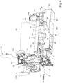
FIG. 3] FIG. 3 is a side view illustrating configurations of a battery support and an inverter support. - [
FIG. 4] FIG. 4 is a perspective view illustrating configurations of a battery support and an inverter support. - [
FIG. 5] FIG. 5 is a perspective view of a vehicle body frame and a support frame. - [
FIG. 6] FIG. 6 is a perspective view of a vehicle body frame and a rear frame. - [
FIG. 7] FIG. 7 is a perspective view of a back surface of a rear frame. - [
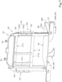
FIG. 8] FIG. 8 is a top perspective view of a battery support. - [
FIG. 9] FIG. 9 is a bottom perspective view of a battery support. - [
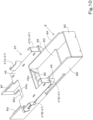
FIG. 10] FIG. 10 is a top perspective view of an inverter support. - [
FIG. 11] FIG. 11 is a bottom perspective view of an inverter support. - [
FIG. 12] FIG. 12 is a side view illustrating an arrangement relationship between an electric motor and an inverter. - [
FIG. 13] FIG. 13 is a perspective view illustrating a structure that transmits power from an electric motor to a hydraulic pump. - [
FIG. 14] FIG. 14 is a perspective view of mounted components provided at a front portion of a vehicle body frame as viewed from the front right. - [
FIG. 15] FIG. 15 is a perspective view of mounted components provided at a front portion of a vehicle body frame as viewed from the rear left. - [
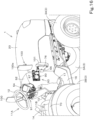
FIG. 16] FIG. 16 is a perspective view of a front portion of an operator portion as viewed from the rear right. - [
FIG. 17] FIG. 17 is a side view of a front portion of an operator portion. - [
FIG. 18] FIG. 18 is a plan view of a front portion of an operator portion. - [
FIG. 19] FIG. 19 is a back view of a front portion of an operator portion. - [
FIG. 20] FIG. 20 is an exploded perspective view illustrating a mounting structure for a charging connector. - Hereinafter, one embodiment according to the present invention will be described with reference to the drawings, as appropriate.
-
FIG. 1 is a schematic side view illustrating an overall configuration of anelectric tractor 1 according to the present embodiment.FIG. 2 is a schematic plan view of theelectric tractor 1. Theelectric tractor 1 is a tractor in which a travelingdevice 3 that supports avehicle body 2 such that thevehicle body 2 is allowed to travel is driven by anelectric motor 4. - In the present embodiment, the direction of arrow A1 (the direction of forward travel of the electric tractor 1) in
FIG. 1 andFIG. 2 will be referred to as forward, the direction of arrow A2 (the direction of rearward travel of the electric tractor 1) inFIG. 1 andFIG. 2 will be referred to as rearward, and the direction of arrow A3 inFIG. 1 andFIG. 2 will be referred to as a front-rear direction. Accordingly, the far side (the side indicated by arrow B1 inFIG. 2 ) inFIG. 1 is the left side, and the near side (the side indicated by arrow B2 inFIG. 2 ) inFIG. 1 is the right side. The direction of arrow B3 inFIG. 2 will be referred to as the vehicle width direction (width direction of the electric tractor 1). A direction toward the left side or the right side from a widthwise central portion of theelectric tractor 1 along the vehicle width direction will be referred to as an outward widthwise direction. In other words, the outward widthwise direction is a direction away from the center of theelectric tractor 1 in the vehicle width direction. A direction opposite the outward widthwise direction will be referred as an inward widthwise direction. In other words, the inward widthwise direction is a direction toward the center of theelectric tractor 1 in the vehicle width direction. - As illustrated in
FIG. 1 andFIG. 2 , theelectric tractor 1 includes a rollover protective structure (ROPS) 5 as an operator protector. In other words, theelectric tractor 1 is of a type without a cabin surrounding an operator'sseat 6. - As illustrated in
FIG. 1 andFIG. 2 , theelectric tractor 1 includes thevehicle body 2 which is supported by the travelingdevice 3 such that thevehicle body 2 is allowed to travel. The travelingdevice 3 includes left and rightfront wheels 3A located at a front portion of theelectric tractor 1, and left and rightrear wheels 3B located at a rear portion of theelectric tractor 1. Thefront wheels 3A are steerable wheels (steered wheels). Therear wheels 3B are each covered by afender 7. The travelingdevice 3 is not limited to a travelingdevice 3 of a wheel type and may be a travelingdevice 3 of a crawler type. - As illustrated in
FIG. 1 , thevehicle body 2 includes theelectric motor 4, avehicle body frame 8, and atransmission case 9. Theelectric motor 4 is a power source that drives the travelingdevice 3. Theelectric motor 4 is located at a position forward of the operator'sseat 6 and afront steering portion 11A (described later) and at a central portion of theelectric tractor 1 in the vehicle width direction. Thevehicle body frame 8 protrudes forward from theelectric motor 4 and is supported by the left and rightfront wheels 3A. Thetransmission case 9 is located rearward of theelectric motor 4 with a space therebetween and is supported by the left and rightrear wheels 3B. Thetransmission case 9 includes, for example, a transmission case, a differential case, and/or the like. Thetransmission case 9 houses therein a transmission that speed-changes rotational power transmitted from theelectric motor 4 through atransmission shaft 15, a transmission mechanism that transmits the power that has been speed-changed by the transmission to therear wheels 3B, a power takeoff mechanism that takes out the speed-changed power to transmit the power to thefront wheels 3A, and/or the like. Theelectric motor 4, thevehicle body frame 8, and thetransmission case 9 are coupled to each other by a coupling frame (not illustrated). - A rear portion of the
transmission case 9 is provided with a mounting mechanism (not illustrated) such as a three-point linkage mechanism to which a working machine is to be detachably coupled, and a hydraulic mechanism that raises and lowers the mounting mechanism (working machine). - An
operator portion 10 including the operator'sseat 6 and its surroundings is mounted on thevehicle body 2. The periphery of theoperator portion 10 is open. The operator'sseat 6 is located above thetransmission case 9 and is supported by thetransmission case 9. The operator'sseat 6 includes aseat portion 6A for an operator to sit, and abackrest 6B that protrudes upward from a rear portion of theseat portion 6A and supports the back of the operator. Theoperator portion 10 includes a steering portion (front steering portion) 11A located forward of the operator'sseat 6, and steering portions (side steering portions) 11B located leftward and rightward of the operator'sseat 6. - The
front steering portion 11A includes asteering handle 12 for steering operation of the left and rightfront wheels 3A. Theside steering portions 11B each include an operation lever (operation member) 13 and acover body 14 covering a lower portion of theoperation lever 13. Theoperation lever 13 is, for example, an auxiliary transmission lever for changing speed stages of an auxiliary transmission mechanism of the transmission, a PTO lever for operating a PTO shaft that transmits power to a working machine mounted rearward of theelectric tractor 1, a position lever for setting the position of the working machine in the up-down direction, an auxiliary control lever for operating the working machine, and/or the like. - A
floor 16 on which the feet of an operator are to be placed is provided at a position forward of and lower than the operator'sseat 6. At a right portion of thefloor 16, there is aspeed change pedal 17 for changing speed stages of the travelingdevice 3. - As illustrated in
FIG. 1 andFIG. 2 , theelectric tractor 1 includes abattery 18 that supplies electric power to theelectric motor 4, and aninverter 19 that converts direct-current power from thebattery 18 into alternating-current power and supplies the alternating-current power to theelectric motor 4. Thebattery 18 is abattery 18 for traveling. - As illustrated in
FIG. 1 andFIG. 4 , thebattery 18 is located at a position above theelectric motor 4 and above thevehicle body frame 8. In detail, thebattery 18 is located at a position above theelectric motor 4 and thevehicle body frame 8 to overlap theelectric motor 4 and thevehicle body frame 8 when viewed in the up-down direction (in plan view). Thebattery 18 is covered by an openable andclosable hood 20 located forward of the operator'sseat 6. Thevehicle body frame 8 is located below thehood 20. - As illustrated in
FIG. 2 , theelectric motor 4 is located below a rear portion of thebattery 18, and a rear portion of theelectric motor 4 protrudes rearward from thebattery 18. As illustrated inFIG. 3 , a front portion of theelectric motor 4 is provided with a connector (motor's connector) 4A. In the present embodiment, the motor'sconnector 4A is a three-phase connector. The motor'sconnector 4A is provided on a front lower portion (a lower portion of the front surface) of theelectric motor 4. - As illustrated in
FIG. 3 , theinverter 19 is located at a position between the battery 18 (later-described battery support 24) and thevehicle body frame 8 and forward of theelectric motor 4. Theinverter 19 is positioned to overlap theelectric motor 4 when viewed in the front-rear direction. In detail, theinverter 19 is positioned such that aninverter body 19A thereof overlaps an upper portion of theelectric motor 4 when viewed in the front-rear direction. Theinverter 19 is located at a position below a front portion of thebattery 18 to overlap thebattery 18 when viewed in the up-down direction. A lower portion of theinverter 19 is provided with a connector (inverter's connector) 19B that is connected to the motor's connector 4Aby a wire (three-phase wire, seeFIG. 12 ) 21. In the present embodiment, the inverter'sconnector 19B is a three-phase connector. The inverter'sconnector 19B is provided at a lower surface of a rear portion of theinverter 19 and protrudes downward from theinverter body 19A. - As illustrated in
FIG. 3 ,FIG. 4 , andFIG. 5 , theelectric tractor 1 includes asupport frame 22 attached to thevehicle body frame 8. Thebattery 18 and theinverter 19 are attached to and supported on thesupport frame 22. - As illustrated in
FIG. 6 , thevehicle body frame 8 includes, mainly, afirst side plate 8A, asecond side plate 8B, and afront plate 8C. Thefirst side plate 8A and thesecond side plate 8B are arranged such that plate surfaces thereof face in the vehicle width direction. Thefirst side plate 8A and thesecond side plate 8B are arranged adjacent to each other with a space therebetween in the vehicle width direction. - As illustrated in
FIG. 4 , thefirst side plate 8A protrudes forward from one of the opposite sides of theelectric motor 4 in the vehicle width direction. Thesecond side plate 8B extends forward from the other of the opposite sides of theelectric motor 4 in the vehicle width direction and faces thefirst side plate 8A in the vehicle width direction. - The
front plate 8C is positioned such that plate surfaces thereof face in the front-rear direction and is fixed to front portions of thefirst side plate 8A and thesecond side plate 8B. In detail, thefront plate 8C extends from the front end of thefirst side plate 8A to the front end of thesecond side plate 8B and couples the front ends of thefirst side plate 8A and thesecond side plate 8B to each other. - The
vehicle body frame 8 includescoupling plates plates coupling plates front coupling plate 8D and arear coupling plate 8E. Thefront coupling plate 8D is positioned such that plate surfaces thereof face in the up-down direction, and couples the lower ends of front portions of thefirst side plate 8A and thesecond side plate 8B to each other at a position rearward of thefront plate 8C. Therear coupling plate 8E is positioned such that plate surfaces thereof face in the up-down direction, and couples vertical intermediate portions of thefirst side plate 8A and thesecond side plate 8B to each other at a position rearward of thefront coupling plate 8D. Therear coupling plate 8E has, in a rear portion thereof, a cutout 8Ea with an open rear to prevent interfere with the motor'sconnector 4A of theelectric motor 4. The reinforcingplate 8F is located at one edge portion of therear coupling plate 8E above therear coupling plate 8E, and is fixed to the inner side of thefirst side plate 8A. The reinforcingplate 8G is located at the opposite edge portion of therear coupling plate 8E above therear coupling plate 8E, and is fixed to the inner side of thesecond side plate 8B. - As illustrated in
FIG. 5 , thesupport frame 22 includes a rear frame (frame member) 23, thebattery support 24, and aninverter support 25. - As illustrated in
FIG. 6 andFIG. 7 , therear frame 23 includes amain frame 26, anupper frame 27, and asupport portion 28. - The
main frame 26 includes afirst pillar member 29, asecond pillar member 30, and acoupling frame body 31. Thefirst pillar member 29 constitutes one of the opposite portions of themain frame 26 in the vehicle width direction. Thesecond pillar member 30 constitutes the other of the opposite portions of themain frame 26 in the vehicle width direction. Thecoupling frame body 31 couples thefirst pillar member 29 and thesecond pillar member 30 to each other. Thecoupling frame body 31 includes a firstvertical member 31A fixed to the front surface of thefirst pillar member 29, a secondvertical member 31B fixed to the front surface of thesecond pillar member 30, a firstlateral member 31C coupling upper portions of the firstvertical member 31A and the secondvertical member 31B to each other, and asecond lateral member 31D coupling intermediate portions of the firstvertical member 31A and the secondvertical member 31B to each other. As illustrated inFIG. 5 , arestriction plate 32 including arestriction portion 32a protruding forward from thesecond pillar member 30 is fixed to an upper portion of thesecond pillar member 30. - As illustrated in
FIG. 7 , mountingplate 33 are fixed to an upper portion of the rear surface of thefirst pillar member 29 and an upper portion of the rear surface of thesecond pillar member 30 so as to protrude rearward. Each of the mountingplates 33 includes avertical plate portion 33a positioned such that plate surfaces thereof face in the vehicle width direction, and anextension plate portion 33b extending in the inward widthwise direction from the upper end of thevertical plate portion 33a. - As illustrated in
FIG. 6 andFIG. 7 , theupper frame 27 is attached to the firstlateral member 31C. Theupper frame 27 is provided with one or more support pins 34 each of which supports an upper portion of a rear portion of thehood 20 such that thehood 20 is rotatable about an axis extending in the vehicle width direction. - The
support portion 28 includes asupport plate 35 protruding forward from a lower portion of themain frame 26, and support leg(s) 36 provided on the same side of thesupport plate 35 as a lower surface of thesupport plate 35. Thesupport plate 35 includes amain plate portion 35a positioned such that plate surfaces thereof face in the up-down direction, and anextension plate portion 35b extending downward from the front end of themain plate portion 35a. As illustrated inFIG. 3 , thesupport plate 35 is located above theelectric motor 4. The reinforcing plate(s) 37 are fixed to left and right portions of the lower surface of themain plate portion 35a, respectively. Thesupport legs 36 are provided at a left portion and a right portion of the lower surface of a front portion of thesupport plate 35. Thesupport legs 36 are fixed to thevehicle body frame 8. In detail, asupport leg 36L on the left portion is fixed to the upper end of a rear portion of thefirst side plate 8A, and asupport leg 36R on the right portion is fixed to the upper end of a rear portion of thesecond side plate 8B. - Note that a rear portion of the support portion 28 (support plate 35) is supported by the
vehicle body 2 via support member(s). - As illustrated in
FIG. 8 andFIG. 9 , thebattery support 24 includes aplacement plate 38 for placement of thebattery 18, and at least one mountingbracket 39 protruding downward from theplacement plate 38. As illustrated inFIG. 3 , theplacement plate 38 is positioned such that plate surfaces thereof face in the up-down direction and is located above theelectric motor 4 and thevehicle body frame 8, and a rear portion of theplacement plate 38 is placed on thesupport plate 35. It follows that the rear portion of the placement plate 38 (rear portion of the battery support 24) is supported by thesupport portion 28. A rear end portion of theplacement plate 38 is attached to thesupport plate 35 with bolt(s) and/or the like. - As illustrated in
FIG. 8 andFIG. 9 , afirst side plate 41 extending in the front-rear direction is fixed to one of the opposite sides of theplacement plate 38 in the vehicle width direction, asecond side plate 42 extending in the front-rear direction is fixed to the other of the opposite sides of theplacement plate 38 in the vehicle width direction, afront plate 43 extending in the vehicle width direction is fixed to a front portion of theplacement plate 38, and arear plate 44 extending in the vehicle width direction is fixed to a rear portion of theplacement plate 38. Thefirst side plate 41, thesecond side plate 42, and thefront plate 43 each have a vertical intermediate portion of a plate surface thereof fixed to an edge portion of theplacement plate 38, and protrude upward and downward from theplacement plate 38. Therear plate 44 is fixed to the upper surface of theplacement plate 38. Rearward movement of thebattery 18 placed on theplacement plate 38 is restricted by therear plate 44, and thebattery 18 is detachably attached to thefirst side plate 41, thesecond side plate 42, and thefront plate 43 with bolts and/or the like. Thebattery 18 is also fixed to therestriction portion 32a of therestriction plate 32 on an upper portion of the second pillar member 30 (seeFIG. 3 ) with bolts and/or the like. - As illustrated in
FIG. 8 andFIG. 9 , there are a plurality of the mountingbrackets 39 in the present embodiment, and the mountingbrackets 39 are located below theplacement plate 38. Specifically, the plurality of mountingbrackets 39 include afirst bracket 39A located at an intermediate portion in the front-rear direction of the inner side of thefirst side plate 41, asecond bracket 39B located at an intermediate portion in the front-rear direction of the inner side of thesecond side plate 42, athird bracket 39C located at a left portion of the inner side of thefront plate 43, and afourth bracket 39D located at a right portion of the inner side of thefront plate 43. In the present embodiment, thefirst bracket 39A and thesecond bracket 39B are made of channel steel, and thethird bracket 39C and thefourth bracket 39D are made of angle steel. This does not imply any limitation. - The
first bracket 39A to thefourth bracket 39D are attached via a mountingframe 45 to thefirst side plate 41, thesecond side plate 42, and thefront plate 43. The mountingframe 45 includes afirst plate member 45A that is attached to the inner side of thefirst side plate 41 with bolts and/or the like, asecond plate member 45B that is attached to the inner side of thesecond side plate 42 with bolts and/or the like, and athird plate member 45C that is attached to the inner side of thefront plate 43 with bolts and/or the like. Thefirst bracket 39A is fixed to a rear portion of thefirst plate member 45A, thesecond bracket 39B is fixed to a rear portion of thesecond plate member 45B, thethird bracket 39C is fixed to a left portion of thethird plate member 45C, and thefourth bracket 39D is fixed to a right portion of thethird plate member 45C. - As illustrated in
FIG. 3 andFIG. 5 , theinverter support 25 is located below a front portion of theplacement plate 38, is fixed to thevehicle body frame 8, and supports the front portion of theplacement plate 38. - As illustrated in
FIG. 10 andFIG. 11 , theinverter support 25 includes a supportingplate 46 and at least one supportingstay 47 protruding upward from the supportingplate 46. The supportingplate 46 is located below theplacement plate 38 with a space therebetween (seeFIG. 3 ). The supportingplate 46 is positioned such that plate surfaces thereof face in the up-down direction and the supportingplate 46 bridges the gap between the upper end of thefirst side plate 8A and the upper end of thesecond side plate 8B. A front portion of the supportingplate 46 has acutout 46a with an open front. A rear portion of the supportingplate 46 has acutout 46b with an open rear. A left portion of the supportingplate 46 protrudes leftward from thefirst side plate 8A. A right portion of the supportingplate 46 protrudes rightward from thesecond side plate 8B. Mountingtools 48 are fixed to a front portion and a rear portion of the lower surface of the right protruding portion of the supportingplate 46.Similar mounting tools 48 are fixed also to the lower surface of the left protruding portion of the supportingplate 46. The mountingtools 48 at the left portion of the supportingplate 46 are attached to thefirst side plate 8A with bolts and/or the like, and the mountingtools 48 at the right portion of the supportingplate 46 are attached to thesecond side plate 8B with bolts and/or the like. Theinverter support 25 is thus attached to thevehicle body frame 8. - There are a plurality of the supporting stays 47. The plurality of the supporting stays 47 include a
first stay 47A, asecond stay 47B, athird stay 47C, and afourth stay 47D. In the present embodiment, thefirst stay 47A and thesecond stay 47B are made of channel steel, and thethird stay 47C and thefourth stay 47D are made of angle steel. This does not imply any limitation. Thefirst stay 47A is fixed and positioned at a rear portion of the left portion of the supportingplate 46 such that the first stay 17A corresponds to itscorresponding mounting tool 48. Thesecond stay 47B is fixed and positioned at a rear portion of the right portion of the supportingplate 46 such that the second stay 17B corresponds to itscorresponding mounting tool 48. Thethird stay 47C is fixed and positioned at a front portion of the left portion of the supportingplate 46 such that thethird stay 47C corresponds to itscorresponding mounting tool 48. Thefourth stay 47D is fixed and positioned at a front portion of the right portion of the supportingplate 46 such that thefourth stay 47D corresponds to itscorresponding mounting tool 48. - The
first bracket 39A is attached to thefirst stay 47A, thesecond bracket 39B is attached to thesecond stay 47B, thethird bracket 39C is attached to thethird stay 47C, and thefourth bracket 39D is attached to thefourth stay 47D (seeFIG. 3 ,FIG. 4 , andFIG. 5 ). It follows that thebattery support 24 is attached to theinverter support 25 such that a space in which theinverter 19 can be placed is formed between theplacement plate 38 and the supportingplate 46. - The
inverter body 19A is placed on the supportingplate 46 and is attached to the supportingplate 46 such that theinverter body 19A is adjustable in position in the front-rear direction. The inverter'sconnector 19B is provided on the lower surface of a front portion of theinverter 19 to protrude downward from theinverter body 19A, and protrudes downward from the supporting plate 46 (inverter support 25) through thecutout 46a. - As illustrated in
FIG. 3 andFIG. 12 , the motor'sconnector 4A and the inverter'sconnector 19B are located between thefirst side plate 8A and thesecond side plate 8B. With this configuration, the motor'sconnector 4A, the inverter'sconnector 19B, and awire 21 can be protected by thefirst side plate 8A and thesecond side plate 8B. Furthermore, the motor'sconnector 4A, the inverter'sconnector 19B, and thewire 21 can be prevented from being damaged, and higher reliability can be achieved. - As illustrated in
FIG. 12 , a wire connection port of the motor'sconnector 4A is oriented forward, and a wire connection port of the inverter'sconnector 19B is oriented rearward. In other words, the motor'sconnector 4A and the inverter'sconnector 19B face each other in the front-rear direction. Furthermore, the motor'sconnector 4A and the inverter'sconnector 19B are arranged to overlap each other when viewed in the front-rear direction. Therefore, the motor'sconnector 4A and the inverter'sconnector 19B can be connected by a short path, preventing or reducing generation of heat by thewire 21 and bringing about an improvement in efficiency of a system. Further, since thewire 21 is short, cost reduction can be achieved. Furthermore, since thewire 21 is short and bending of thewire 21 can be minimized, it is possible to reduce the likelihood that thewire 21 will be damaged due to external factors, and possible to achieve improvement in reliability. - As illustrated in
FIG. 12 , awater pump 94 is attached to the front coupling plate(s) 8D and/or 8E of thevehicle body frame 8. Thewater pump 94 is a pump that circulates cooling water for cooling theelectric motor 4, theinverter 19, a voltage converter (described later), and/or the like. - As illustrated in
FIG. 3 andFIG. 4 , a hydraulic pump P1 that is driven by theelectric motor 4 is located on one side of theelectric motor 4. The hydraulic pump P1, for example, sucks oil in the inside of thetransmission case 9 and supplies the oil as hydraulic fluid to each hydraulic driven actuator. As illustrated inFIG. 13 , apower transmitting mechanism 49 is provided behind theelectric motor 4 and the hydraulic pump P1, and thepower transmitting mechanism 49 transmits power from theelectric motor 4 to the hydraulic pump P1. As illustrated inFIG. 4 , thepower transmitting mechanism 49 is covered by acover case 61. Thecover case 61 has an opening facing forward. - As illustrated in
FIG. 13 , thepower transmitting mechanism 49 includes a gear transmission mechanism. Thepower transmitting mechanism 49 includes arotatable output gear 51 that is coupled to an output shaft of theelectric motor 4, aninput gear 52 that is coupled to an input shaft of the hydraulic pump P1, and one more transmission gears 53 that are located between theoutput gear 51 and theinput gear 52 and transmit power from theoutput gear 51 to theinput gear 52. Theoutput gear 51, theinput gear 52, and the transmission gears 53 are each a spur gear and rotate about an axis extending in the front-rear direction. This does not imply any limitation. In the present embodiment, there are a plurality of the transmission gears 53. The plurality of transmission gears 53 include the following three gears: afirst gear 53A that meshes with theoutput gear 51, asecond gear 53B that meshes with thefirst gear 53A, and athird gear 53C that meshes with thesecond gear 53B and theinput gear 52. - As illustrated in
FIG. 14 andFIG. 15 , a radiator R1, a voltage converter (DCDC converter) C1, a battery BT for auxiliary machine(s), a reserve tank R2, a cooling fan F1, an oil cooler O1, and/or the like are located forward of thebattery support 24 and attached to and supported on a front portion of thevehicle body frame 8. - As illustrated in
FIG. 14 , the radiator R1, the voltage converter C1, and the battery BT for auxiliary machine(s) are arranged in this order from the left in the vehicle width direction. The reserve tank R2 is located above the battery BT for auxiliary machine(s). As illustrated inFIG. 15 , the cooling fan F1 is located rearward of the radiator R1, and the oil cooler O1 is located rearward of the cooling fan F1. - The radiator R1 is a heat dissipater that cools, with cooling air generated by the cooling fan F1, cooling water circulated by the
water pump 94. The voltage converter C1 is a device that steps down electric power sent from thebattery 18 and supplies the electric power to the battery BT for auxiliary machine(s). The battery BT for auxiliary machine(s) is a storage battery that supplies electric power to controller(s) that controls electrical machines such as the cooling fan F1, theinverter 19, and theelectric motor 4, and to electrical device(s) such as lamp(s). The reserve tank R2 is a tank for storing cooling water that escapes from the radiator R1 when temperature is high. The oil cooler O1 is a heat dissipater that cools, with cooling air generated by the cooling fan F1, hydraulic fluid for actuating hydraulic device(s) and/or the like. - As illustrated in
FIG. 16 to FIG. 19 , thefront steering portion 11A of theoperator portion 10 includes a chargingconnector 90 for charging thebattery 18. As illustrated inFIG. 17 , thefront steering portion 11A includes asteering operation device 91 including thesteering handle 12, and a front cover (cover body) 92 that covers a lower portion of thesteering operation device 91. The front cover 92 (front steering portion 11A) is located upward of thevehicle body 2 and mounted on the vehicle body. In other words, thefront cover 92 extends upward from thevehicle body 2. Thefront cover 92 protrudes upward from thefloor 16. The steering handle 12 is located at an upper portion of the rear surface of thefront cover 92. An upper portion of thefront cover 92 is provided with aninstrument panel 54 including a monitor, meters, switches, and/or the like. Theinstrument panel 54 is provided with a battery level meter that indicates the amount of charge in thebattery 18. Thefront cover 92 is located rearward of and near thehood 20 and has an opening facing forward. The rear end of thehood 20 has an opening facing rearward. It follows that thefront cover 92 and thehood 20 are in communication with each other. The rear frame 23 (main frame 26) of thesupport frame 22 is located at a rear end portion of thehood 20, and the mountingplates 33 provided on therear frame 23 are configured to be inserted into thefront cover 92. - As illustrated in
FIG. 17 , thesteering operation device 91 includes: a steering operation member (operation member) 86 including the steering handle 12 and a steeringshaft 56; asteering post 57 that supports the steeringshaft 56; a steeringvalve 58 that is connected to the steeringshaft 56 via auniversal joint 62; and aframe member 59 that supports the steeringpost 57, the steeringvalve 58, and the like. Thefront cover 92 thus covers a lower portion of thesteering operation member 86. Theframe member 59 is attached to and supported by a member that is attached on thevehicle body 2 side, such as therear frame 23. - In the aforementioned
steering operation device 91, when the steering handle 12 is rotationally operated, the steeringvalve 58 is operated via the steeringshaft 56 and theuniversal joint 62, and the steeringvalve 58 supplies hydraulic fluid supplied from the hydraulic pump P1 to a steering cylinder (not illustrated) that steers thefront wheels 3A. - As illustrated in
FIG. 16 andFIG. 19 , the chargingconnector 90 is located outside (at the outer surface of) the front cover 92 (cover body) and exposed outward of the front cover 92 (front steering portion 11A). Furthermore, the chargingconnector 90 is located at a side (right side) of thefront cover 92 such that the chargingconnector 90 is oriented in the outward widthwise direction (rightward). Further, as illustrated inFIG. 17 , the chargingconnector 90 is located forward of and below thesteering handle 12. Furthermore, as illustrated inFIG. 1 , the chargingconnector 90 is located at an upper portion of the outer surface of thefront cover 92 such that the height position thereof is substantially the same as the height position of theseat portion 6A of the operator'sseat 6. The right side of thefront cover 92 is open to allow a foot to be placed on the portion of thefloor 16 that is below the chargingconnector 90 to perform charging. A passage space is formed between thefront cover 92 and thefenders 7. - As illustrated in
FIG. 18 , the chargingconnector 90 includes: aconnector body 96 including aconnection terminal portion 96a; acap 97 that openably closes theconnection terminal portion 96a side of theconnector body 96; and awire terminal portion 96b. - The
connection terminal portion 96a is a portion to which apower supplying connector 64 is connected. Thepower supplying connector 64 is provided at, for example, an external power supply system such as a charging system in a charging facility called a charging stand or a charging station or in a house. - The
connector body 96 is located outward in the outward widthwise direction (rightward) of the steering handle 12 and located outward of the operator'sseat 6 in the outward widthwise direction. - As illustrated in
FIG. 17 , thecap 97 is attached to theconnector body 96 such that apivotal support portion 97a provided at a front portion of thecap 97 is rotatable about a vertical axis (an axis extending in the up-down direction). A lockingmember 98 that detachably engages thecap 97 and restricts opening movement of thecap 97 is provided rearward of thecap 97. The lockingmember 98 is pivotally supported on theconnector body 96 and capable of removing the restriction of the opening movement of thecap 97 by being rotated about the vertical axis. It is possible to cause theconnection terminal portion 96a of theconnector body 96 to be exposed outward in the vehicle width direction by opening (rotating) thecap 97 toward the front about the vertical axis. - As illustrated in
FIG. 18 , thewire terminal portion 96b protrudes from the back surface of theconnector body 96 and is inserted in thefront cover 92. Thewire terminal portion 96b is a portion for connection with a connection wire that connects the chargingconnector 90 and thebattery 18. When thepower supplying connector 64 of an external power source is connected to theconnection terminal portion 96a, thebattery 18 charged with electricity from thewire terminal portion 96b through the connection wire. - As illustrated in
FIG. 16 andFIG. 17 , anindicator lamp 101 and aside mirror 100 are located forward of the chargingconnector 90. Theindicator lamp 101 is, for example, a combination lamp including a combination of a plurality of lamps. The lamps included in the combination lamp are position lamp(s), winker lamp(s), hazard lamp(s), and/or the like. Theside mirror 100 is a mirror to visually check an area rearward of thevehicle body 2. Theindicator lamp 101 and amirror body 100a of theside mirror 100 are located at a position forward of the chargingconnector 90 and outward of the chargingconnector 90 in the outward widthwise direction. - As illustrated in
FIG. 19 , the chargingconnector 90 is attached to aconnector bracket 93. As illustrated inFIG. 20 , theconnector bracket 93 includes afirst bracket member 66 and asecond bracket member 67. Thefirst bracket member 66 includes: a mountingwall portion 66a that is placed on and attached to thevertical plate portion 33a of one of the mounting plates (mounting portion) 33 provided on therear frame 23; anextension wall portion 66b extending in the outward widthwise direction from the front edge of the mountingwall portion 66a; alamp mounting portion 66c extending rearward from the distal edge (an edge portion located on outer one of the opposite sides in the vehicle width direction) of theextension wall portion 66b; and areinforcement member 69 including a pipe member and/or the like coupling the mountingwall portion 66a and thelamp mounting portion 66c to each other. Theextension wall portion 66b protrudes in the outward widthwise direction from the inner side of thefront cover 92 and has at least one mountinghole 68 at the protruding portion of theextension wall portion 66b. - The
second bracket member 67 includes afirst member 71 attached to thefirst bracket member 66, and asecond member 72 fixed to thefirst member 71. Thefirst member 71 includes afirst wall portion 71a arranged such that plate surfaces thereof face in the vehicle width direction, and asecond wall portion 71b extending in the outward widthwise direction from a lower portion of the front edge of thefirst wall portion 71a and attached to the portion of theextension wall portion 66b that has the mounting hole(s) 68. Thesecond member 72 is fixed such that thesecond member 72 protrudes rearward from thefirst wall portion 71a of thefirst member 71. In the present embodiment, thesecond member 72 extends such that thesecond member 72 is inclined outward in the vehicle width direction (inclined leftward) with decreasing distance to the rear. The chargingconnector 90 is attached to thesecond member 72 from the outer side in the vehicle width direction. In other words, thesecond member 72 is a connector mounting portion to which the chargingconnector 90 is attached. - As described above, the
connector bracket 93 includes the connector mounting portion (second member 72) to which the chargingconnector 90 is attached outside thefront cover 92, and the mountingwall portion 66a attached to the mounting portion (mounting plate 33) provided inside thefront cover 92. - As illustrated in
FIG. 20 , apillar member 73 for theside mirror 100 is attached to an upper portion of thefirst member 71 of thesecond bracket member 67 via a mountingtool 74. The upper portion of thefirst member 71 thus functions as amirror mounting portion 75 to which theside mirror 100 is attached. Alamp stay 76 for theindicator lamp 101 is attached to thelamp mounting portion 66c of thefirst bracket member 66. - As described above, the
connector bracket 93 includes themirror mounting portion 75 to which theside mirror 100 is attached, and thelamp mounting portion 66c to which theindicator lamp 101 is attached. - The charging
connector 90 can be located outside (at the outer surface of) thecover body 14 of one of the side steering portion(s) 11B. In other words, the cover body provided in the vicinity of the operator'sseat 6 and covering a lower portion of the operation member is provided with the chargingconnector 90. - An
electric tractor 1 as has been discussed includes anelectric motor 4 to drive a travelingdevice 3, abattery 18, aninverter 19 to supply electric power from thebattery 18 to theelectric motor 4, avehicle body frame 8 located below ahood 20 located forward of an operator'sseat 6 to cover thebattery 18, and asupport frame 22 attached to thevehicle body frame 8, wherein thesupport frame 22 includes abattery support 24 to support thebattery 18 located at a position above theelectric motor 4 and above thevehicle body frame 8, and aninverter support 25 to support theinverter 19 located at a position between thebattery support 24 and thevehicle body frame 8 and forward of theelectric motor 4. - This configuration includes the
battery support 24 which supports thebattery 18 located at a position above theelectric motor 4 and above thevehicle body frame 8, and theinverter support 25 which supports theinverter 19 located at a position between thebattery support 24 and thevehicle body frame 8 and forward of theelectric motor 4. It is thus possible to place theelectric motor 4 and theinverter 19 at positions close to each other and possible to couple theelectric motor 4 and theinverter 19 by a short path. - The
battery support 24 includes aplacement plate 38 for placement of thebattery 18, and a mountingbracket 39 protruding downward from theplacement plate 38. Theinverter support 25 includes a supportingplate 46 for placement of theinverter 19, the supportingplate 46 being located below theplacement plate 38 with a space interposed between the supportingplate 46 and theplacement plate 38 and being attached to thevehicle body frame 8, and asupport stay 47 which protrudes upward from the supportingplate 46 and to which the mountingbracket 39 is attached. - With this configuration, a space in which the
inverter 19 is placed can be formed at a position below thebattery 18 and forward of theelectric motor 4. - The
inverter support 25 supports theinverter 19 such that theinverter 19 is positioned to overlap theelectric motor 4 when viewed in a front-rear direction. - With this configuration, the
electric motor 4 and theinverter 19 can be arranged compactly. - The
support frame 22 includes asupport portion 28 located below a rear portion of theplacement plate 38, thesupport portion 28 being fixed to thevehicle body frame 8 to support the rear portion of theplacement plate 38. Theinverter support 25 supports a front portion of theplacement plate 38. - With this configuration, the
battery 18 can be sufficiently supported by thesupport portion 28 and theinverter support 25. - The
support portion 28 includes asupport plate 35 for placement of the rear portion of theplacement plate 38, thesupport plate 35 being located above theelectric motor 4, and asupport leg 36 provided on the same side of thesupport plate 35 as a lower surface of thesupport plate 35 and fixed to thevehicle body frame 8. - Since the
support plate 35 is located above theelectric motor 4, thesupport portion 28 and theelectric motor 4 can be arranged compactly. - The
electric motor 4 includes a motor'sconnector 4A provided on a front portion of theelectric motor 4. Theinverter 19 includes an inverter'sconnecter 19B connected to the motor'sconnector 4A, the inverter'sconnector 19B being located forward of the motor'sconnector 4A. - With this configuration, the motor's
connector 4A and the inverter'sconnector 19B can be connected to each other through a short path. - The motor's
connector 4A is provided on a front lower portion of theelectric motor 4. Theinverter 19 is positioned such that aninverter body 19A thereof placed and supported on theinverter support 25 is located rearward of an upper portion of theelectric motor 4 and theinverter body 19A overlaps the upper portion of theelectric motor 4 when viewed in a front-rear direction. The inverter'sconnector 19B is provided on a lower portion of theinverter body 19A and protrudes downward from theinverter support 25. - Also with this configuration, the motor's
connector 4A and the inverter'sconnector 19B can be connected to each other through a shorter path. - The
inverter support 25 has acutout 46a that allows the inverter'sconnector 19B to protrude downward from theinverter support 25. - This configuration makes it possible to allow the inverter's
connector 19B to protrude downward from theinverter support 25 while supporting theinverter 19 favorably on theinverter support 25. - The
vehicle body frame 8 includes afirst side plate 8A and asecond side plate 8B that are arranged with a space therebetween in a vehicle width direction. The motor'sconnector 4A and the inverter'sconnector 19B are located between thefirst side plate 8A and thesecond side plate 8B. - With this configuration, the motor's
connector 4A and the inverter'sconnector 19B can be protected. - An
electric tractor 1 includes anoperator portion 10 including an operator'sseat 6 and a steering portion (front steering portion 11A) provided in the vicinity of the operator'sseat 6, avehicle body 2 on which theoperator portion 10 is provided, a travelingdevice 3 to support thevehicle body 2 such that the travelingdevice 3 is allowed to travel, anelectric motor 4 to drive the travelingdevice 3, abattery 18 to supply electric power to theelectric motor 4, and a chargingconnector 90 for charging of thebattery 18, wherein thesteering portion 11A includes an operation member (steering operation member 86) and a cover body (front cover 92) to cover a lower portion of theoperation member 86, and the chargingconnector 90 is located outside thecover body 92 to be exposed outward of the steering portion. - With this configuration, the
battery 18 can be charged easily. - The charging
connector 90 is located at a side of thecover body 92 such that the chargingconnector 90 is oriented outward in a vehicle width direction. - With this configuration, the
battery 18 can be charged more easily. - The
steering portion 11A includes asteering operation member 86 that is located forward of the operator'sseat 6 to function as the operation member, and afront cover 92 that covers a lower portion of thesteering operation member 86 to function as the cover body. The chargingconnector 90 is located on an upper portion of an outer surface of thefront cover 92. - With this configuration, the charging
connector 90 can be positioned such that a power supplying connector of an external power source is easily connected to the chargingconnector 90. - The
steering operation member 86 includes asteering handle 12. The chargingconnector 90 is located forward of thesteering handle 12. - This configuration makes it possible to eliminate or reduce the likelihood that the steering handle 12 will prevent a connector of an external power source from being connected to the charging
connector 90. - The charging
connector 90 is located on the outer surface of thefront cover 92 such that a height position of the chargingconnector 90 is substantially the same as a height position of aseat portion 6A of the operator'sseat 6. - Also with this configuration, the charging
connector 90 can be positioned such that a power supplying connector of an external power source is easily connected to the chargingconnector 90. - The
electric tractor 1 includes aconnector bracket 93 to which the chargingconnector 90 is attached. Theconnector bracket 93 includes a connector mounting portion (second member 72) to which the chargingconnector 90 is attached outside thefront cover 92, and a mountingwall portion 66a attached to a mounting portion (mounting plate 33) provided inside thefront cover 92. - With this configuration, the
connector bracket 93 can be sufficiently supported, and the chargingconnector 90 can be easily attached. - The
connector bracket 93 includes amirror mounting portion 75 to which aside mirror 100 is attached. - With this configuration, a member functions as two or more members, making it possible to reduce cost.
- The
connector bracket 93 includes alamp mounting portion 66c to which anindicator lamp 101 is attached. - Also with this configuration, a member functions as two or more members, making it possible to reduce cost.
- While embodiments of the present invention have been described above, it is to be understood that the embodiments disclosed herein are considered as examples in all aspects and are not considered as limitations. The scope of the present invention is to be determined not by the foregoing description but by the claims, and is intended to include all variations and modifications within the scope of the claims and their equivalents.
-
- 2
- vehicle body
- 3
- traveling device
- 4
- electric motor
- 4A
- motor's connector
- 6
- operator's seat
- 6A
- seat portion
- 8
- vehicle body frame
- 8A
- first side plate
- 8B
- second side plate
- 10
- operator portion
- 11A
- steering portion (front steering portion)
- 12
- steering handle
- 18
- battery
- 19
- inverter
- 19A
- inverter body
- 19B
- inverter's connector
- 20
- hood
- 22
- support frame
- 24
- battery support
- 25
- inverter support
- 28
- support portion
- 33
- mounting portion (mounting plate)
- 35
- support plate
- 36
- support leg
- 38
- placement plate
- 39
- mounting bracket
- 46
- supporting plate
- 46a
- cutout
- 47
- support stay
- 66a
- mounting wall portion
- 66c
- lamp mounting portion
- 72
- connector mounting portion (second member)
- 75
- mirror mounting portion
- 86
- operation member (steering operation member)
- 90
- charging connector
- 92
- cover body (front cover)
- 93
- connector bracket
- 100
- side mirror
- 101
- indicator lamp
Claims (17)
- An electric tractor comprising:an electric motor to drive a traveling device;a battery;an inverter to supply electric power from the battery to the electric motor;a vehicle body frame located below a hood located forward of an operator's seat to cover the battery; anda support frame attached to the vehicle body frame, whereinthe support frame includesa battery support to support the battery located at a position above the electric motor and above the vehicle body frame, andan inverter support to support the inverter located at a position between the battery support and the vehicle body frame and forward of the electric motor.
- The electric tractor according to claim 1, whereinthe battery support includesa placement plate for placement of the battery, anda mounting bracket protruding downward from the placement plate, andthe inverter support includesa supporting plate for placement of the inverter, the supporting plate being located below the placement plate with a space interposed between the supporting plate and the placement plate and being attached to the vehicle body frame, anda support stay which protrudes upward from the supporting plate and to which the mounting bracket is attached.
- The electric tractor according to claim 1 or 2, wherein the inverter support supports the inverter such that the inverter is positioned to overlap the electric motor when viewed in a front-rear direction.
- The electric tractor according to claim 2 or 3, whereinthe support frame includes a support portion located below a rear portion of the placement plate, the support portion being fixed to the vehicle body frame to support the rear portion of the placement plate, andthe inverter support supports a front portion of the placement plate.
- The electric tractor according to claim 4, wherein the support portion includesa support plate for placement of the rear portion of the placement plate, the support plate being located above the electric motor, anda support leg provided on the same side of the support plate as a lower surface of the support plate and fixed to the vehicle body frame.
- The electric tractor according to any one of claims 1 to 5, whereinthe electric motor includes a motor's connector provided on a front portion of the electric motor, andthe inverter includes an inverter's connecter connected to the motor's connector, the inverter's connector being located forward of the motor's connector.
- The electric tractor according to claim 6, whereinthe motor's connector is provided on a front lower portion of the electric motor,the inverter is positioned such that an inverter body thereof placed and supported on the inverter support is located rearward of an upper portion of the electric motor and the inverter body overlaps the upper portion of the electric motor when viewed in a front-rear direction, andthe inverter's connector is provided on a lower portion of the inverter body and protrudes downward from the inverter support.
- The electric tractor according to claim 7, wherein the inverter support has a cutout that allows the inverter's connector to protrude downward from the inverter support.
- The electric tractor according to any one of claims 6 to 8, whereinthe vehicle body frame includes a first side plate and a second side plate that are arranged with a space therebetween in a vehicle width direction, andthe motor's connector and the inverter's connector are located between the first side plate and the second side plate.
- An electric tractor comprising:an operator portion including an operator's seat and a steering portion provided in the vicinity of the operator's seat;a vehicle body on which the operator portion is provided;a traveling device to support the vehicle body such that the traveling device is allowed to travel;an electric motor to drive the traveling device;a battery to supply electric power to the electric motor; anda charging connector for charging of the battery, whereinthe steering portion includes an operation member and a cover body to cover a lower portion of the operation member, andthe charging connector is located outside the cover body to be exposed outward of the steering portion.
- The electric tractor according to claim 10, wherein the charging connector is located at a side of the cover body such that the charging connector is oriented outward in a vehicle width direction.
- The electric tractor according to claim 10 or 11, whereinthe steering portion includes a steering operation member that is located forward of the operator's seat to function as the operation member, and a front cover that covers a lower portion of the steering operation member to function as the cover body, andthe charging connector is located on an upper portion of an outer surface of the front cover.
- The electric tractor according to claim 12, whereinthe steering operation member includes a steering handle, andthe charging connector is located forward of the steering handle.
- The electric tractor according to claim 12 or 13, wherein the charging connector is located on the outer surface of the front cover such that a height position of the charging connector is substantially the same as a height position of a seat portion of the operator's seat.
- The electric tractor according to any one of claims 10 to 14, comprising:a connector bracket to which the charging connector is attached, whereinthe connector bracket includes a connector mounting portion to which the charging connector is attached outside the front cover, and a mounting wall portion attached to a mounting portion provided inside of the front cover.
- The electric tractor according to claim 15, wherein the connector bracket includes a mirror mounting portion to which a side mirror is attached.
- The electric tractor according to claim 15 or 16, wherein the connector bracket includes a lamp mounting portion to which an indicator lamp is attached.
Applications Claiming Priority (3)
| Application Number | Priority Date | Filing Date | Title |
|---|---|---|---|
| JP2020168258A JP7458956B2 (en) | 2020-10-05 | 2020-10-05 | Electric Tractor |
| JP2020168259A JP7524020B2 (en) | 2020-10-05 | 2020-10-05 | Electric Tractor |
| PCT/JP2021/036369 WO2022075206A1 (en) | 2020-10-05 | 2021-10-01 | Electric tractor |
Publications (2)
| Publication Number | Publication Date |
|---|---|
| EP4227192A1 true EP4227192A1 (en) | 2023-08-16 |
| EP4227192A4 EP4227192A4 (en) | 2025-04-02 |
Family
ID=81126899
Family Applications (1)
| Application Number | Title | Priority Date | Filing Date |
|---|---|---|---|
| EP21877505.4A Pending EP4227192A4 (en) | 2020-10-05 | 2021-10-01 | Electric tractor |
Country Status (3)
| Country | Link |
|---|---|
| US (1) | US20230227106A1 (en) |
| EP (1) | EP4227192A4 (en) |
| WO (1) | WO2022075206A1 (en) |
Cited By (2)
| Publication number | Priority date | Publication date | Assignee | Title |
|---|---|---|---|---|
| DE102023131380A1 (en) * | 2023-11-10 | 2025-05-15 | Tadus GmbH | Tractor substructure for an electrically powered agricultural tractor |
| EP4609690A4 (en) * | 2023-01-17 | 2026-02-18 | Nanjing Chervon Ind Co Ltd | Riding lawn mower |
Families Citing this family (11)
| Publication number | Priority date | Publication date | Assignee | Title |
|---|---|---|---|---|
| JP7323349B2 (en) * | 2019-06-24 | 2023-08-08 | 株式会社クボタ | electric work vehicle |
| JP2023178908A (en) | 2022-06-06 | 2023-12-18 | 株式会社 神崎高級工機製作所 | electric work vehicle |
| CN115056866A (en) * | 2022-06-30 | 2022-09-16 | 上海十联重工有限公司 | Electric tractor of safety and stability efficient |
| JP2025007878A (en) * | 2023-07-03 | 2025-01-17 | 株式会社クボタ | Electric work vehicle |
| JP2025042488A (en) * | 2023-09-14 | 2025-03-27 | ヤンマーホールディングス株式会社 | Electrical work machinery |
| US12603343B2 (en) * | 2023-10-30 | 2026-04-14 | Kubota Corporation | Component layout of liquid cooling components in electric work vehicle |
| US20250135861A1 (en) * | 2023-10-30 | 2025-05-01 | Kubota Corporation | Component layout of electric components in electric work vehicle |
| US20250140958A1 (en) * | 2023-10-30 | 2025-05-01 | Kubota Corporation | Component layout of air cooling components in electric work vehicle |
| EP4678448A1 (en) | 2024-07-12 | 2026-01-14 | Deere & Company | Drive assembly, axle and working machine |
| EP4678437A1 (en) | 2024-07-12 | 2026-01-14 | Deere & Company | Drive assembly, axle and working machine |
| EP4678444A1 (en) | 2024-07-12 | 2026-01-14 | Deere & Company | Drive assembly, axle and working machine |
Family Cites Families (20)
| Publication number | Priority date | Publication date | Assignee | Title |
|---|---|---|---|---|
| JP2002167181A (en) * | 2000-11-28 | 2002-06-11 | Nippon Yusoki Co Ltd | Battery protection structure |
| US20110046831A1 (en) * | 2009-02-11 | 2011-02-24 | Ananthakrishna Anil | Electrically powered motorized vehicle with continuously variable transmission and combined hybrid system |
| JP5836033B2 (en) | 2011-09-22 | 2015-12-24 | 株式会社クボタ | Tractor power extraction structure |
| KR101302405B1 (en) * | 2011-10-14 | 2013-09-02 | 대동공업주식회사 | Electric vehicle construction for agriculture |
| JP5946845B2 (en) * | 2011-12-22 | 2016-07-06 | ヤマハ発動機株式会社 | Straddle-type electric vehicle |
| EP2796352B1 (en) * | 2011-12-22 | 2021-03-03 | Yamaha Hatsudoki Kabushiki Kaisha | Saddled electric vehicle |
| JP6471626B2 (en) | 2015-06-22 | 2019-02-20 | 井関農機株式会社 | Tractor |
| CN205800763U (en) * | 2015-06-25 | 2016-12-14 | 井关农机株式会社 | Vehicle |
| JP6290847B2 (en) * | 2015-10-22 | 2018-03-07 | 本田技研工業株式会社 | Connector mounting structure for electric vehicles |
| AU2020362049A1 (en) * | 2019-10-11 | 2022-05-19 | Ariens Company | Power source and control system for a lawn mower |
| CN112829867A (en) * | 2020-11-10 | 2021-05-25 | 浙江春风动力股份有限公司 | High-strength electric motorcycle |
| JP2023015904A (en) * | 2021-07-20 | 2023-02-01 | ヤマハ発動機株式会社 | Saddle riding electric vehicle |
| JP2023015905A (en) * | 2021-07-20 | 2023-02-01 | ヤマハ発動機株式会社 | electric vehicle |
| EP4527177A3 (en) * | 2021-09-18 | 2025-05-07 | Nanjing Chervon Industry Co., Ltd. | Riding lawn mower, display interface of a power tool and riding machine |
| US12024037B2 (en) * | 2021-11-03 | 2024-07-02 | Zero Motorcycles, Inc. | Charging system, vehicle including a charging system, and charging method |
| US12595028B2 (en) * | 2022-04-07 | 2026-04-07 | Taiga Motors Inc. | Protective cover for electric vehicle |
| JP7696866B2 (en) * | 2022-06-23 | 2025-06-23 | 株式会社クボタ | Work Machine |
| US20250125442A1 (en) * | 2023-10-13 | 2025-04-17 | Kubota Corporation | Air cooling system for an electric vehicle |
| US20250135923A1 (en) * | 2023-10-30 | 2025-05-01 | Kubota Corporation | Electric work vehicle including plurality of external charge ports |
| US12603343B2 (en) * | 2023-10-30 | 2026-04-14 | Kubota Corporation | Component layout of liquid cooling components in electric work vehicle |
-
2021
- 2021-10-01 WO PCT/JP2021/036369 patent/WO2022075206A1/en not_active Ceased
- 2021-10-01 EP EP21877505.4A patent/EP4227192A4/en active Pending
-
2023
- 2023-03-27 US US18/126,636 patent/US20230227106A1/en active Pending
Cited By (2)
| Publication number | Priority date | Publication date | Assignee | Title |
|---|---|---|---|---|
| EP4609690A4 (en) * | 2023-01-17 | 2026-02-18 | Nanjing Chervon Ind Co Ltd | Riding lawn mower |
| DE102023131380A1 (en) * | 2023-11-10 | 2025-05-15 | Tadus GmbH | Tractor substructure for an electrically powered agricultural tractor |
Also Published As
| Publication number | Publication date |
|---|---|
| EP4227192A4 (en) | 2025-04-02 |
| US20230227106A1 (en) | 2023-07-20 |
| WO2022075206A1 (en) | 2022-04-14 |
Similar Documents
| Publication | Publication Date | Title |
|---|---|---|
| US20230227106A1 (en) | Electric tractor | |
| JP7524020B2 (en) | Electric Tractor | |
| JP7631585B2 (en) | Electric Tractor | |
| JP5814577B2 (en) | Electric work vehicle and battery holding structure thereof | |
| JP5814578B2 (en) | Electric work vehicle and its base frame | |
| EP4265852A1 (en) | Construction equipment | |
| JP2012202066A (en) | Electric working vehicle and power source unit for the same | |
| JP7675643B2 (en) | electric work vehicle | |
| JP2025007878A (en) | Electric work vehicle | |
| JP7720960B2 (en) | electric work vehicle | |
| US20240317079A1 (en) | Electric work vehicle | |
| JP7546543B2 (en) | Electric work vehicle | |
| EP4342707B1 (en) | Work vehicle | |
| EP4644150A1 (en) | Electric work vehicle | |
| JP7555326B2 (en) | Electric work vehicle | |
| JP2024164319A5 (en) | ||
| US20260070424A1 (en) | Work vehicle | |
| JP7797372B2 (en) | Work vehicles | |
| JP7519982B2 (en) | Electric work vehicle | |
| US20250289334A1 (en) | Electric work vehicle | |
| US20240123845A1 (en) | Electric Work Vehicle | |
| JP2025143143A (en) | Work vehicle | |
| JP2024095104A (en) | Work vehicles | |
| JP2024095105A (en) | Work vehicles | |
| JP2017177985A (en) | Work vehicle |
Legal Events
| Date | Code | Title | Description |
|---|---|---|---|
| STAA | Information on the status of an ep patent application or granted ep patent |
Free format text: STATUS: THE INTERNATIONAL PUBLICATION HAS BEEN MADE |
|
| PUAI | Public reference made under article 153(3) epc to a published international application that has entered the european phase |
Free format text: ORIGINAL CODE: 0009012 |
|
| STAA | Information on the status of an ep patent application or granted ep patent |
Free format text: STATUS: REQUEST FOR EXAMINATION WAS MADE |
|
| 17P | Request for examination filed |
Effective date: 20230504 |
|
| AK | Designated contracting states |
Kind code of ref document: A1 Designated state(s): AL AT BE BG CH CY CZ DE DK EE ES FI FR GB GR HR HU IE IS IT LI LT LU LV MC MK MT NL NO PL PT RO RS SE SI SK SM TR |
|
| DAV | Request for validation of the european patent (deleted) | ||
| DAX | Request for extension of the european patent (deleted) | ||
| A4 | Supplementary search report drawn up and despatched |
Effective date: 20250304 |
|
| RIC1 | Information provided on ipc code assigned before grant |
Ipc: B60L 50/60 20190101ALN20250226BHEP Ipc: B60K 15/05 20060101ALN20250226BHEP Ipc: B60K 1/00 20060101ALN20250226BHEP Ipc: B60K 1/04 20190101ALI20250226BHEP Ipc: B62D 49/00 20060101ALI20250226BHEP Ipc: B62D 21/02 20060101AFI20250226BHEP |
|
| GRAP | Despatch of communication of intention to grant a patent |
Free format text: ORIGINAL CODE: EPIDOSNIGR1 |
|
| STAA | Information on the status of an ep patent application or granted ep patent |
Free format text: STATUS: GRANT OF PATENT IS INTENDED |
|
| RIC1 | Information provided on ipc code assigned before grant |
Ipc: B62D 21/02 20060101AFI20251222BHEP Ipc: B60K 15/05 20060101ALN20251222BHEP Ipc: B60L 50/60 20190101ALN20251222BHEP Ipc: B62D 49/00 20060101ALI20251222BHEP Ipc: B60K 1/04 20190101ALI20251222BHEP Ipc: B60K 1/00 20060101ALN20251222BHEP |
|
| INTG | Intention to grant announced |
Effective date: 20260122 |