EP4227181B1 - Anti-skid control method for transfer case - Google Patents
Anti-skid control method for transfer case Download PDFInfo
- Publication number
- EP4227181B1 EP4227181B1 EP22784140.0A EP22784140A EP4227181B1 EP 4227181 B1 EP4227181 B1 EP 4227181B1 EP 22784140 A EP22784140 A EP 22784140A EP 4227181 B1 EP4227181 B1 EP 4227181B1
- Authority
- EP
- European Patent Office
- Prior art keywords
- vehicle
- denotes
- target
- speed
- control parameter
- Prior art date
- Legal status (The legal status is an assumption and is not a legal conclusion. Google has not performed a legal analysis and makes no representation as to the accuracy of the status listed.)
- Active
Links
Images


Classifications
-
- B—PERFORMING OPERATIONS; TRANSPORTING
- B60—VEHICLES IN GENERAL
- B60K—ARRANGEMENT OR MOUNTING OF PROPULSION UNITS OR OF TRANSMISSIONS IN VEHICLES; ARRANGEMENT OR MOUNTING OF PLURAL DIVERSE PRIME-MOVERS IN VEHICLES; AUXILIARY DRIVES FOR VEHICLES; INSTRUMENTATION OR DASHBOARDS FOR VEHICLES; ARRANGEMENTS IN CONNECTION WITH COOLING, AIR INTAKE, GAS EXHAUST OR FUEL SUPPLY OF PROPULSION UNITS IN VEHICLES
- B60K28/00—Safety devices for propulsion-unit control, specially adapted for, or arranged in, vehicles, e.g. preventing fuel supply or ignition in the event of potentially dangerous conditions
- B60K28/10—Safety devices for propulsion-unit control, specially adapted for, or arranged in, vehicles, e.g. preventing fuel supply or ignition in the event of potentially dangerous conditions responsive to conditions relating to the vehicle
- B60K28/16—Safety devices for propulsion-unit control, specially adapted for, or arranged in, vehicles, e.g. preventing fuel supply or ignition in the event of potentially dangerous conditions responsive to conditions relating to the vehicle responsive to, or preventing, spinning or skidding of wheels
- B60K28/165—Safety devices for propulsion-unit control, specially adapted for, or arranged in, vehicles, e.g. preventing fuel supply or ignition in the event of potentially dangerous conditions responsive to conditions relating to the vehicle responsive to, or preventing, spinning or skidding of wheels acting on elements of the vehicle drive train other than the propulsion unit and brakes, e.g. transmission, clutch, differential
-
- B—PERFORMING OPERATIONS; TRANSPORTING
- B60—VEHICLES IN GENERAL
- B60W—CONJOINT CONTROL OF VEHICLE SUB-UNITS OF DIFFERENT TYPE OR DIFFERENT FUNCTION; CONTROL SYSTEMS SPECIALLY ADAPTED FOR HYBRID VEHICLES; ROAD VEHICLE DRIVE CONTROL SYSTEMS FOR PURPOSES NOT RELATED TO THE CONTROL OF A PARTICULAR SUB-UNIT
- B60W10/00—Conjoint control of vehicle sub-units of different type or different function
- B60W10/30—Conjoint control of vehicle sub-units of different type or different function including control of auxiliary equipment, e.g. air-conditioning compressors or oil pumps
-
- B—PERFORMING OPERATIONS; TRANSPORTING
- B60—VEHICLES IN GENERAL
- B60W—CONJOINT CONTROL OF VEHICLE SUB-UNITS OF DIFFERENT TYPE OR DIFFERENT FUNCTION; CONTROL SYSTEMS SPECIALLY ADAPTED FOR HYBRID VEHICLES; ROAD VEHICLE DRIVE CONTROL SYSTEMS FOR PURPOSES NOT RELATED TO THE CONTROL OF A PARTICULAR SUB-UNIT
- B60W10/00—Conjoint control of vehicle sub-units of different type or different function
- B60W10/119—Conjoint control of vehicle sub-units of different type or different function including control of all-wheel-driveline means, e.g. transfer gears or clutches for dividing torque between front and rear axle
-
- B—PERFORMING OPERATIONS; TRANSPORTING
- B60—VEHICLES IN GENERAL
- B60W—CONJOINT CONTROL OF VEHICLE SUB-UNITS OF DIFFERENT TYPE OR DIFFERENT FUNCTION; CONTROL SYSTEMS SPECIALLY ADAPTED FOR HYBRID VEHICLES; ROAD VEHICLE DRIVE CONTROL SYSTEMS FOR PURPOSES NOT RELATED TO THE CONTROL OF A PARTICULAR SUB-UNIT
- B60W30/00—Purposes of road vehicle drive control systems not related to the control of a particular sub-unit, e.g. of systems using conjoint control of vehicle sub-units
- B60W30/02—Control of vehicle driving stability
-
- B—PERFORMING OPERATIONS; TRANSPORTING
- B60—VEHICLES IN GENERAL
- B60W—CONJOINT CONTROL OF VEHICLE SUB-UNITS OF DIFFERENT TYPE OR DIFFERENT FUNCTION; CONTROL SYSTEMS SPECIALLY ADAPTED FOR HYBRID VEHICLES; ROAD VEHICLE DRIVE CONTROL SYSTEMS FOR PURPOSES NOT RELATED TO THE CONTROL OF A PARTICULAR SUB-UNIT
- B60W30/00—Purposes of road vehicle drive control systems not related to the control of a particular sub-unit, e.g. of systems using conjoint control of vehicle sub-units
- B60W30/18—Propelling the vehicle
- B60W30/18172—Preventing, or responsive to skidding of wheels
-
- B—PERFORMING OPERATIONS; TRANSPORTING
- B60—VEHICLES IN GENERAL
- B60W—CONJOINT CONTROL OF VEHICLE SUB-UNITS OF DIFFERENT TYPE OR DIFFERENT FUNCTION; CONTROL SYSTEMS SPECIALLY ADAPTED FOR HYBRID VEHICLES; ROAD VEHICLE DRIVE CONTROL SYSTEMS FOR PURPOSES NOT RELATED TO THE CONTROL OF A PARTICULAR SUB-UNIT
- B60W40/00—Estimation or calculation of non-directly measurable driving parameters for road vehicle drive control systems not related to the control of a particular sub unit, e.g. by using mathematical models
-
- B—PERFORMING OPERATIONS; TRANSPORTING
- B60—VEHICLES IN GENERAL
- B60W—CONJOINT CONTROL OF VEHICLE SUB-UNITS OF DIFFERENT TYPE OR DIFFERENT FUNCTION; CONTROL SYSTEMS SPECIALLY ADAPTED FOR HYBRID VEHICLES; ROAD VEHICLE DRIVE CONTROL SYSTEMS FOR PURPOSES NOT RELATED TO THE CONTROL OF A PARTICULAR SUB-UNIT
- B60W50/00—Details of control systems for road vehicle drive control not related to the control of a particular sub-unit, e.g. process diagnostic or vehicle driver interfaces
- B60W2050/0001—Details of the control system
- B60W2050/0002—Automatic control, details of type of controller or control system architecture
- B60W2050/0008—Feedback, closed loop systems or details of feedback error signal
- B60W2050/001—Proportional integral [PI] controller
-
- B—PERFORMING OPERATIONS; TRANSPORTING
- B60—VEHICLES IN GENERAL
- B60W—CONJOINT CONTROL OF VEHICLE SUB-UNITS OF DIFFERENT TYPE OR DIFFERENT FUNCTION; CONTROL SYSTEMS SPECIALLY ADAPTED FOR HYBRID VEHICLES; ROAD VEHICLE DRIVE CONTROL SYSTEMS FOR PURPOSES NOT RELATED TO THE CONTROL OF A PARTICULAR SUB-UNIT
- B60W2300/00—Indexing codes relating to the type of vehicle
- B60W2300/18—Four-wheel drive vehicles
-
- B—PERFORMING OPERATIONS; TRANSPORTING
- B60—VEHICLES IN GENERAL
- B60W—CONJOINT CONTROL OF VEHICLE SUB-UNITS OF DIFFERENT TYPE OR DIFFERENT FUNCTION; CONTROL SYSTEMS SPECIALLY ADAPTED FOR HYBRID VEHICLES; ROAD VEHICLE DRIVE CONTROL SYSTEMS FOR PURPOSES NOT RELATED TO THE CONTROL OF A PARTICULAR SUB-UNIT
- B60W2510/00—Input parameters relating to a particular sub-units
- B60W2510/20—Steering systems
- B60W2510/207—Oversteer or understeer
-
- B—PERFORMING OPERATIONS; TRANSPORTING
- B60—VEHICLES IN GENERAL
- B60W—CONJOINT CONTROL OF VEHICLE SUB-UNITS OF DIFFERENT TYPE OR DIFFERENT FUNCTION; CONTROL SYSTEMS SPECIALLY ADAPTED FOR HYBRID VEHICLES; ROAD VEHICLE DRIVE CONTROL SYSTEMS FOR PURPOSES NOT RELATED TO THE CONTROL OF A PARTICULAR SUB-UNIT
- B60W2520/00—Input parameters relating to overall vehicle dynamics
- B60W2520/12—Lateral speed
- B60W2520/125—Lateral acceleration
-
- B—PERFORMING OPERATIONS; TRANSPORTING
- B60—VEHICLES IN GENERAL
- B60W—CONJOINT CONTROL OF VEHICLE SUB-UNITS OF DIFFERENT TYPE OR DIFFERENT FUNCTION; CONTROL SYSTEMS SPECIALLY ADAPTED FOR HYBRID VEHICLES; ROAD VEHICLE DRIVE CONTROL SYSTEMS FOR PURPOSES NOT RELATED TO THE CONTROL OF A PARTICULAR SUB-UNIT
- B60W2520/00—Input parameters relating to overall vehicle dynamics
- B60W2520/14—Yaw
-
- B—PERFORMING OPERATIONS; TRANSPORTING
- B60—VEHICLES IN GENERAL
- B60W—CONJOINT CONTROL OF VEHICLE SUB-UNITS OF DIFFERENT TYPE OR DIFFERENT FUNCTION; CONTROL SYSTEMS SPECIALLY ADAPTED FOR HYBRID VEHICLES; ROAD VEHICLE DRIVE CONTROL SYSTEMS FOR PURPOSES NOT RELATED TO THE CONTROL OF A PARTICULAR SUB-UNIT
- B60W2520/00—Input parameters relating to overall vehicle dynamics
- B60W2520/28—Wheel speed
-
- B—PERFORMING OPERATIONS; TRANSPORTING
- B60—VEHICLES IN GENERAL
- B60W—CONJOINT CONTROL OF VEHICLE SUB-UNITS OF DIFFERENT TYPE OR DIFFERENT FUNCTION; CONTROL SYSTEMS SPECIALLY ADAPTED FOR HYBRID VEHICLES; ROAD VEHICLE DRIVE CONTROL SYSTEMS FOR PURPOSES NOT RELATED TO THE CONTROL OF A PARTICULAR SUB-UNIT
- B60W2540/00—Input parameters relating to occupants
- B60W2540/10—Accelerator pedal position
-
- B—PERFORMING OPERATIONS; TRANSPORTING
- B60—VEHICLES IN GENERAL
- B60W—CONJOINT CONTROL OF VEHICLE SUB-UNITS OF DIFFERENT TYPE OR DIFFERENT FUNCTION; CONTROL SYSTEMS SPECIALLY ADAPTED FOR HYBRID VEHICLES; ROAD VEHICLE DRIVE CONTROL SYSTEMS FOR PURPOSES NOT RELATED TO THE CONTROL OF A PARTICULAR SUB-UNIT
- B60W2540/00—Input parameters relating to occupants
- B60W2540/18—Steering angle
-
- B—PERFORMING OPERATIONS; TRANSPORTING
- B60—VEHICLES IN GENERAL
- B60W—CONJOINT CONTROL OF VEHICLE SUB-UNITS OF DIFFERENT TYPE OR DIFFERENT FUNCTION; CONTROL SYSTEMS SPECIALLY ADAPTED FOR HYBRID VEHICLES; ROAD VEHICLE DRIVE CONTROL SYSTEMS FOR PURPOSES NOT RELATED TO THE CONTROL OF A PARTICULAR SUB-UNIT
- B60W2720/00—Output or target parameters relating to overall vehicle dynamics
- B60W2720/28—Wheel speed
-
- B—PERFORMING OPERATIONS; TRANSPORTING
- B60—VEHICLES IN GENERAL
- B60W—CONJOINT CONTROL OF VEHICLE SUB-UNITS OF DIFFERENT TYPE OR DIFFERENT FUNCTION; CONTROL SYSTEMS SPECIALLY ADAPTED FOR HYBRID VEHICLES; ROAD VEHICLE DRIVE CONTROL SYSTEMS FOR PURPOSES NOT RELATED TO THE CONTROL OF A PARTICULAR SUB-UNIT
- B60W2720/00—Output or target parameters relating to overall vehicle dynamics
- B60W2720/40—Torque distribution
- B60W2720/403—Torque distribution between front and rear axle
Definitions
- the present invention relates to the technical field of anti-slip control, and in particular to an anti-skid control method for transfer case.
- the anti-skid control for the four-wheel-drive transfer case is mainly based on threshold value control, that is, according to the magnitude of a speed difference between the front axle and the rear axle of the vehicle, an anti-skid control coefficient and a specific engagement torque value of the transfer case are determined; in response to the speed difference being greater than a preset threshold value, the engagement torque of the transfer case is quickly increased to achieve four-wheel-drive torque distribution; and in response to the speed difference being less than the preset threshold value, the engagement torque of the transfer case is decreased to achieve high-efficiency two-wheel-drive driving.
- threshold value control is, according to the magnitude of a speed difference between the front axle and the rear axle of the vehicle, an anti-skid control coefficient and a specific engagement torque value of the transfer case are determined; in response to the speed difference being greater than a preset threshold value, the engagement torque of the transfer case is quickly increased to achieve four-wheel-drive torque distribution; and in response to the speed difference being less than the preset threshold value, the engagement torque of the transfer case is decreased to
- At least some embodiments of the present invention provides an anti-skid control method for transfer case, which is configured to adjust an engagement control torque of the transfer case in real time while avoiding the influence of anti-slip fluctuation and torque fluctuation of a vehicle to ensure the driving performance and stability of the whole vehicle.
- An embodiment of present invention provides an anti-skid control method for transfer case, including the following steps:
- An embodiment of present invention provides an electronic device, including:
- An embodiment of present invention further provides a computer-readable storage medium, wherein the computer-readable storage medium is configured to store a computer program, and in response to executed by a processor, the computer program implements the anti-skid control method for transfer case as claimed in an embodiment of the present invention.
- an anti-skid control method for transfer case in which the influence on the fluctuation of an engagement control torque of the transfer case of a vehicle under various conditions, such as acceleration, steering, lateral deviation and other conditions, are comprehensively considered, and multiple control parameters of the vehicle can be adjusted in real time, thereby realizing a stable anti-slip closed-loop control function of the vehicle, to avoid trackslip of the vehicle to ensure the driving performance and stability of the vehicle.
- the vehicle is a vehicle equipped with a timely four-wheel-drive transfer case.
- the anti-skid control method for transfer case includes the following steps:
- step S30 calculating the engagement control torque T target of the transfer case:
- the engagement control torque T target of the transfer case is configured to increase currently, and the corrected proportional integral control parameters k p and k l are both positive values currently; and in response to ⁇ v, m ⁇ 0, the main driving shaft being in the over-trackslip state, the control parameter factor b is determined based on the specific driving condition of the vehicle currently to decrease the control parameter to reduce the engagement control torque T target of the transfer case and to reduce the descent speed of the engagement control torque T target , thereby prolonging the anti-skid control time to avoid the problem of rotating speed fluctuation and acceleration fluctuation of the vehicle, which are caused by the fluctuation of the engagement control torque T target .
- the minimum accelerator opening degree of the vehicle in the trackslip state is wherein a min, k-1 denotes the minimum accelerator opening degree of the vehicle at the previous time, and TCS denotes a traction control system of the vehicle.
- the control parameter factor b max ( b ⁇ , b v , b sw , b coast ); wherein b ⁇ denotes a steering wheel rotation angle control factor of the vehicle, and 0 ⁇ b ⁇ ⁇ 1, b v denotes a vehicle speed control parameter factor of the vehicle, and 0 ⁇ b v ⁇ 1, b sw denotes a control parameter factor of the vehicle under a steering condition, b coast denotes a slip control parameter factor of the vehicle, in response to the vehicle is in a slip driving condition and performing the anti-skid control, the slip control parameter factor b coast being equal to 1, and in response to the vehicle is in the slip driving condition and exits anti-skid control, the slip control parameter factor b coast being equal to 0.
- b sw max b ⁇ , b ay , b y b T and b ay denotes a lateral acceleration control parameter factor, b y denotes a yaw rate control parameter factor, and b T denotes a torque control parameter factor under a steering acceleration condition.
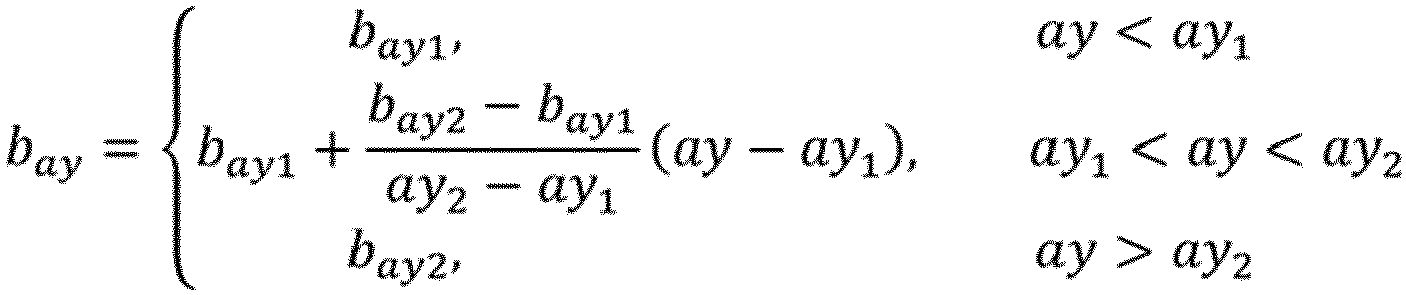
- b ay b ay 1 , ay ⁇ ay 1 b ay 1 + b ay 2 ⁇ b ay 1 ay 2 ⁇ ay 1 ay ⁇ ay 1 , ay 1 ⁇ ay ⁇ ay 2 b ay 2 , ay > ay 2 and ay denotes a lateral acceleration of the vehicle, and the unit is of the lateral acceleration is m/s 2 ; both ay 1 and ay 2 denote lateral acceleration calibration values of the vehicle, ay 1 and ay 2 are determined values, and the unit is of the lateral acceleration calibration value is m/s 2 ; and both b ay1 and b ay2 denote calibration values of a lateral acceleration control parameter of the vehicle, and b ay1 and b ay2 are determined values.
- b y b y 1 , y ⁇ y 1 b y 1 + b y 2 ⁇ b y 1 y 2 ⁇ y 1 y ⁇ y 1 , y 1 ⁇ y ⁇ y 2 b y 2 , y > y 2 and y denotes a yaw rate of the vehicle, and the unit of the yaw rate is rad/s; both y 1 and y 2 denote yaw rate calibration values of the vehicle, y 1 and y 2 are determined values, and the unit of the yaw rate calibration value is rad/s; and both b y1 and b y2 denote calibration values of a yaw rate control parameter of the vehicle, and b y1 and b y2 are determined values.
- b T b T 1 , T ⁇ T 1 b T 1 + b T 2 ⁇ b T 1 T 2 ⁇ T 1 T ⁇ T 1 , T 1 ⁇ T ⁇ T 2 b T 2 , T > T 2 and T denotes a driving torque of the vehicle, and the unit of the driving torque is N ⁇ m; both T 1 and T 2 denote driving torque calibration values of the vehicle, T 1 and T 2 are determined values, and the unit of the driving torque calibration value is N ⁇ m; and both b T1 and b T2 denote calibration values of a driving torque control parameter of the vehicle, and b T1 and b T2 are determined values.
- v s , target max v m , F ⁇ ⁇ L sin ⁇ cos ⁇ 1 + ⁇ 0 , v m , F
- v min MAP ( v x 0 , v y 0, min )
- FIG. 3 it shows a schematic structural diagram of an electronic device (e.g., a terminal device or a server in Fig. 3 ) 600 suitable for implementing the embodiments of the present invention.
- the terminal device in the embodiments of the present invention include, but is not limited to, mobile terminals such as a mobile phone, a notebook computer, a digital broadcast receiver, a PDA (Personal Digital Assistant), a PAD (Tablet computer), a PMP (Portable Multimedia Player), an on-board terminal (e.g., an on-board navigation terminal), and other mobile terminals, and fixed terminals such as a digital TV, a desktop computer, and other fixed terminals.
- the electronic device shown in Fig. 3 is an example, and should not bring any limitation to the functions and use ranges of the embodiments of the present invention.
- the electronic device 600 include a processing apparatus (e.g., a central processor, a graphics processor, and other processing apparatus) 601, which execute multiple appropriate actions and processing based on programs stored in a read only memory (ROM) 602 or programs loaded into a random access memory (RAM) 603 from a storage apparatus 608. In the RAM 603, various programs and data required for the operations of the electronic device 600 are also stored.
- the processing apparatus 601, the ROM 602 and the RAM 603 are connected with each other through a bus 604.
- An input/output (I/O) interface 605 is also connected to the bus 604.
- an input apparatus 606 including, for example, a touch screen, a touchpad, a keyboard, a mouse, a camera, a microphone, an accelerometer, a gyroscope and other input apparatuses
- an output apparatus 607 including, for example, a liquid crystal display (LCD), a loudspeaker, a vibrator, and the like
- the storage apparatus 608 including, for example, a magnetic tape, a hard disk, and the like
- a communication apparatus 609 allow the electronic device 600 to perform wired or wireless communication with other devices to exchange data.
- Fig. 3 shows the electronic device 600 is configured with multiple apparatuses, it should be understood that, it is not required to implement or have all illustrated apparatuses. More or fewer apparatuses are configured to be alternatively implemented or provided.
- the computer-readable medium can be contained in the electronic device; and the computer-readable medium can also exist alone, and is not assembled in the electronic device.
- the computer-readable medium carries at least one program, and in response to being executed, the at least one program execute the following steps:
- the computer-readable storage medium in the present invention is configured to be a computer-readable signal medium or a computer-readable storage medium or a combination thereof.
- the computer-readable storage medium can be, for example, but is not limited to, electrical, magnetic, optical, electromagnetic, infrared, or semiconductor systems, apparatuses or devices, or a combination of any of the above systems, apparatuses or devices.
- the computer-readable storage medium include, but are not limited to: an electrical connection with at least one wires, a portable computer disk, a hard disk, a random access memory (RAM), a read only memory (ROM), an erasable programmable read only memory (EPROM or a flash memory), an optical fiber, a portable compact disc read only memory (CD-ROM), an optical storage device, a magnetic storage device, or any suitable combination of the above devices.
- the computer-readable storage medium can be any tangible medium that contains or stores a program, and the program can be used by or combined with an instruction execution system, apparatus or device for use.
- the computer-readable signal medium include a data signal, which is propagated in a baseband or as part of a carrier, and a computer-readable program code is carried in the data signal.
- a propagated data signal take multiple forms, including, but not limited to, an electromagnetic signal, an optical signal, or any suitable combination thereof.
- the computer-readable signal medium may also be any computer-readable medium other than the computer-readable storage medium, and the computer-readable signal medium send, propagate or transmit the program, which is taken by or combined with the instruction execution system, apparatus or device for use.
- the program code contained on the computer-readable medium may be transmitted by any suitable medium, including but not limited to: an electric wire, an optical cable, RF (radio frequency), and other suitable mediums, or any suitable combination of the foregoing manners.
Landscapes
- Engineering & Computer Science (AREA)
- Transportation (AREA)
- Mechanical Engineering (AREA)
- Chemical & Material Sciences (AREA)
- Combustion & Propulsion (AREA)
- Automation & Control Theory (AREA)
- Physics & Mathematics (AREA)
- Mathematical Physics (AREA)
- Regulating Braking Force (AREA)
- Arrangement And Driving Of Transmission Devices (AREA)
Description
- The present invention claims the priority of
Chinese Patent Application 202110378352.0, filed to the China Patent Office on April 08, 2021 - The present invention relates to the technical field of anti-slip control, and in particular to an anti-skid control method for transfer case.
- Under a track slip working condition, in response to the main driving wheel of a vehicle equipped with a timely four-wheel-drive transfer case generate track slip, anti-skid control needs to be implemented on the transfer case, that is, the engagement torque of the transfer case needs to be increased or decreased currently to achieve reasonable distribution of driving torques of a front axle and a rear axle of the vehicle again, thereby eliminating an over track slip state and an under track slip state of the main driving wheel to improve the traction performance and stability of the vehicle.
- Currently, the anti-skid control for the four-wheel-drive transfer case is mainly based on threshold value control, that is, according to the magnitude of a speed difference between the front axle and the rear axle of the vehicle, an anti-skid control coefficient and a specific engagement torque value of the transfer case are determined; in response to the speed difference being greater than a preset threshold value, the engagement torque of the transfer case is quickly increased to achieve four-wheel-drive torque distribution; and in response to the speed difference being less than the preset threshold value, the engagement torque of the transfer case is decreased to achieve high-efficiency two-wheel-drive driving. However, in response to the vehicle running on a wet and slippery road surface in an acceleration mode, frequent and repeated engagement torque fluctuation, anti-slip fluctuation and longitudinal acceleration fluctuation of the transfer case are likely to occur, so that the judgment relationship between the speed difference and the threshold value is frequently and repeatedly changed, which is disadvantages to the driving performance and stability of the whole vehicle.
- Document
EP2022659 A1 discloses an anti-skid control method for a transfer case. - In summary, there is an urgent need to configure an anti-skid control method for transfer case to solve the above-mentioned problems.
- At least some embodiments of the present invention provides an anti-skid control method for transfer case, which is configured to adjust an engagement control torque of the transfer case in real time while avoiding the influence of anti-slip fluctuation and torque fluctuation of a vehicle to ensure the driving performance and stability of the whole vehicle.
- The present invention utilizes the following technical solutions:
An embodiment of present invention provides an anti-skid control method for transfer case, including the following steps: - S10: calculating a target speed of a main driving shaft through the following formula: vm, target = max(vs, target, vmin), wherein vm, target denotes the target speed of the main driving shaft, vs, target denotes the speed of the main driving shaft in response to the influence of the steering of a vehicle and the lateral deviation of a tire being considered, and vmin denotes a minimum speed of the vehicle to avoid a wheel speed precision error and a jitter phenomenon of the vehicle under a starting low-speed driving condition;
- S20: determining an anti-skid control condition through the following mode: in response to determining that vm > vm, target (1+λ1), and a time period t of keeping vm > vm, target (1+λ1) is greater than or equal to a time period t1, starting an anti-skid control, and t1 is related to the acceleration of the main driving shaft, vm denotes an average value of the rotating speeds of two wheels at two ends of the main driving shaft, and λ1 denotes a trigger threshold offset of an anti-skid control function under a trackslip condition;
- in an anti-skid control starting state, in response to determining that an engagement control torque Ttarget of the transfer case of the vehicle is equal to 0, and the time period t of keeping Ttarget = 0 is greater than or equal to a time period t2, exiting the anti-skid control, and t2 is a calibration value; and
- S30: calculating the engagement control torque Ttarget of the transfer case through the following formula: Ttarget = Kp△v, m+kl ∫ △v, m, and kp and kl denote a corrected proportional integral control parameters obtained by correcting a control parameter factor b of the vehicle in an over-trackslip state and an under-trackslip state, △v, m denotes a speed control deviation of the main driving shaft, and △v, m = vm - vm, target.
- An embodiment of present invention provides an electronic device, including:
- at least one processor; and
- a memory, configured to store at least one program; and
- in response to the at least one program is executed by the at least one processor, the at least one processor implements the anti-skid control method for transfer case as claimed in an embodiment of the present invention.
- An embodiment of present invention further provides a computer-readable storage medium, wherein the computer-readable storage medium is configured to store a computer program, and in response to executed by a processor, the computer program implements the anti-skid control method for transfer case as claimed in an embodiment of the present invention.
-
-
Fig. 1 is a first schematic flowchart of an anti-skid control method for transfer case according to an embodiment of the present invention; -
Fig. 2 is a second schematic flowchart of an anti-skid control method for transfer case according to an embodiment of the present invention; -
Fig. 3 is a schematic structural diagram of an electronic device according to an embodiment of the present invention. - Throughout the specification, the same reference signs denote the same elements.
- In the present embodiment, an anti-skid control method for transfer case is provided, in which the influence on the fluctuation of an engagement control torque of the transfer case of a vehicle under various conditions, such as acceleration, steering, lateral deviation and other conditions, are comprehensively considered, and multiple control parameters of the vehicle can be adjusted in real time, thereby realizing a stable anti-slip closed-loop control function of the vehicle, to avoid trackslip of the vehicle to ensure the driving performance and stability of the vehicle. In the present embodiment, the vehicle is a vehicle equipped with a timely four-wheel-drive transfer case.
- For example, as shown in
Fig. 1 , the anti-skid control method for transfer case includes the following steps: - In step S10: calculating a target speed of a main driving shaft: vm, target = max(vs, target, vmin), and vm, target denotes the target speed of the main driving shaft, vs, target denotes the speed of the main driving shaft in response to the influence of the steering of a vehicle and the lateral deviation of a tire being considered, and vmin denotes a minimum speed of the vehicle at different vehicle speeds to avoid a wheel speed precision error and a jitter phenomenon of the vehicle under a starting low-speed driving condition;
- In step S20: determining an anti-skid control condition: in response to vm > vm, target (1+λ1), and a time period t of keeping vm > vm, target (1 + λ1) is greater than or equal to a time period t1, starting an anti-skid control, and t1 is related to the acceleration of the main driving shaft, vm denotes an average value of the rotating speeds of two wheels at two ends of the main driving shaft, and λ1 denotes a trigger threshold offset of an anti-skid control function under a trackslip condition;
in an anti-skid control starting state, in response to an engagement control torque Ttarget of the transfer case of the vehicle being equal to 0, and the time period t of keeping Ttarget = 0 is greater than or equal to a time period t2, exiting the anti-skid control, and t2 is a calibration value; and - In step S30: calculating the engagement control torque Ttarget of the transfer case: Ttarget = kp△v, m+kl ∫ △v, m, and kp and kl both denote a corrected proportional integral control parameters obtained by correcting a control parameter factor b of the vehicle in an over-trackslip state and an under-trackslip state, kp and kl may be adapatively adjusted under a linear or steering working condition of the vehicle, Δv, m denotes a speed control deviation of the main driving shaft, and △v, m = vm - vm, target, therefore after the vehicle starts the anti-skid control function, the engagement control torque of the transfer case may be increased or decreased according to the value of Ttarget, which is calculated in real time according to Ttarget = Kp△v, m+kl ∫ △v, m, so as to adjust the Ttarget in real time, and accordingly, trackslip of the vehicle may be avoided.
- By means of calculating the target speed of the main driving shaft: vm, target = max(vs, target, vmin), in response to vm > vm, target (1 + λ1), and the time t of keeping vm > vm, target (1 + λ1) is greater than or equal to t1, the anti-skid control is started; in the anti-skid control starting state, in response to the engagement control torque Ttarget of the transfer case of the vehicle being equal to 0, and the time t of keeping Ttarget = 0 is greater than or equal to t2, the anti-skid control is exited; and after the vehicle starts the anti-skid control, the engagement control torque for transfer case can be increased or decreased based on the value of Ttarget, which is calculated through Ttarget = kp△v, m+kl ∫ △v, m to avoid trackslip of the vehicle. In this way, the driving torques of front and rear axles of the vehicle are reasonably distributed again to reduce the trackslip state of the main driving wheel and to ensure the traction performance and stability of the vehicle.
- During the process of calculating the target speed vm, target of the main driving shaft, the influence of the steering of the vehicle and the lateral deviation of the tire is considered, and the wheel speed precision error and the jitter phenomenon of the vehicle under the starting low-speed driving working condition are avoided; and both the corrected proportional integral control parameters kp and kl involved in the calculation of the engagement control torque Ttarget of the transfer case are obtained by correcting the control parameter factor of the vehicle in the over-trackslip state and the under-trackslip state, and kp and kl are configured to be adapatively adjusted under the linear or steering working condition of the vehicle, therefore anti-slip fluctuation and torque fluctuation of the vehicle under the trackslip working condition can be effectively avoided, thereby adjusting the engagement control torque Ttarget of the transfer case in real time, and realizing an intelligent timely four-wheel-drive anti-slip closed-loop control function. In this way, in response to the vehicle runs on a wet and slippery road surface in an acceleration mode, frequent and repeated engagement torque fluctuation, anti-slip fluctuation and longitudinal acceleration fluctuation of the transfer case, which are disadvantages to the driving performance and stability of the whole vehicle, are avoided.
- For example, in response to △v, m > 0, the main driving shaft being in the under-trackslip state, the engagement control torque Ttarget of the transfer case is configured to increase currently, and the corrected proportional integral control parameters kp and kl are both positive values currently; and in response to △v, m < 0, the main driving shaft being in the over-trackslip state, the control parameter factor b is determined based on the specific driving condition of the vehicle currently to decrease the control parameter to reduce the engagement control torque Ttarget of the transfer case and to reduce the descent speed of the engagement control torque Ttarget, thereby prolonging the anti-skid control time to avoid the problem of rotating speed fluctuation and acceleration fluctuation of the vehicle, which are caused by the fluctuation of the engagement control torque Ttarget.
- For example, as shown in
Fig. 1 , the step S25 is further included between the step S20 and the step S30: calculating the corrected proportional integral control parameters kp and kl:

- For example, in the step S25, in response to the vehicle is in a low-speed linear acceleration driving condition, since the response of the engagement control torque Ttarget of the transfer case is relatively slow and the control precision is relatively low, in order to avoid the phenomena of torque fluctuation, rotating speed fluctuation and other conditions caused by frequent reciprocating of anti-skid control, the decrease of the engagement control torque Ttarget in the anti-skid control of the transfer case can be slowed down by adjusting the control parameter factor b; and the control parameter factor

- For example, the minimum accelerator opening degree of the vehicle in the trackslip state is

- For example, in the step S25, in response to the vehicle is a high-speed acceleration driving condition, the control parameter factor b = max(bδ , bv, bsw, bcoast ); wherein bδ denotes a steering wheel rotation angle control factor of the vehicle, and 0≤bδ≤1, bv denotes a vehicle speed control parameter factor of the vehicle, and 0≤bv≤1, bsw denotes a control parameter factor of the vehicle under a steering condition, bcoast denotes a slip control parameter factor of the vehicle, in response to the vehicle is in a slip driving condition and performing the anti-skid control, the slip control parameter factor bcoast being equal to 1, and in response to the vehicle is in the slip driving condition and exits anti-skid control, the slip control parameter factor bcoast being equal to 0.
- Under a steering acceleration driving condition, the steering wheel rotation angle control factor bδ of the vehicle increases with the increase of the absolute value of a steering wheel rotation angle, the absolute value of a lateral acceleration and the absolute value of a yaw rate, thereby avoiding a steering braking phenomenon caused by the excessively large engagement control torque of the transfer case under the steering working condition, that is, the calculation formula of the steering wheel rotation angle control factor bδ of the vehicle is as follow:

- For example, under a high-speed acceleration driving condition, the vehicle speed control parameter factor bv decreases with the increase of the vehicle speed, thereby avoiding excessive intervention in the anti-skid control under the high-speed acceleration driving condition, that is, the calculation formula of the vehicle speed control parameter factor bv of the vehicle is as follow:

- The calculation formula of the control parameter factor bsw of the vehicle under the steering working condition is as follow:

- For example, the calculation formula of the lateral acceleration control parameter factor bay is as follow:

- For example, the calculation formula of the yaw rate control parameter factor by is as follow:

- For example, since the torque control parameter factor bT under the steering acceleration condition increases along with the increase of the driving torque of the driving shaft, that is, the calculation formula of bT is as follow:

- For example, in response to the main driving shaft is a rear axle, the influence of the steering of the vehicle and the lateral deviation of the tire being considered at the same time:

- wherein, λ0 denotes a target trackslip rate; θ denotes a front wheel rotation angle of the vehicle, and the unit of the front wheel rotation angle is rad; γ denotes the yaw rate of the vehicle, and the unit of the yaw rate is rad/s; vm, F denotes an average value of the rotating speeds of the two wheels at the two ends of the front axle, that is, the average value of the rotating speeds of a left front wheel and a right front wheel, and the unit of the average value of the rotating speed is m/s; and L denotes a wheelbase, and the unit of the wheelbase is m; and
- in response to the main driving shaft is a front axle, the influence of the steering of the vehicle and the lateral deviation of the tire being considered at the same time:

- and vm, R denotes an average value of the rotating speeds of the two wheels at the two ends of the rear axle, that is, the average value of the rotating speeds of a left rear wheel and a right rear wheel, and the unit of the average value of the rotating speed is m/s.
- For example, in order to avoid the wheel speed precision error and the jitter phenomenon of the vehicle under the low-speed driving condition such as starting, the calculation formula of the minimum speed vmin of the vehicle at different vehicle speeds is as follow:

- For example, in order to enable the vehicle to quickly start the anti-skid control under a severe trackslip condition, it is judged that the time t1 is related to the acceleration of the main driving shaft, and the calculation formula of the time t1 is as follow:

- The control process of the anti-skid control method for transfer case in the present embodiment is as follows: as shown in
Fig. 2 , the front axle is taken as the main driving shaft: first, vs, target is calculated through vs, target = max ((vm,R cos θ + γL sin θ)(1 + γ 0), vm,R ), and vm, R denotes the speed of the rear axle, that is, the average value of the rotating speeds of the two wheels at the two ends of the rear axle; and vmin is calculated through , and then the target speed vm, target of the front axle is calculated through vm, target = max(vs, target, vmin). vmin = MAP(v x0, v y0,min ) - Then, t1 is calculated through

- Next, it is judged through △v, m > 0 or Δv, m < 0 that, the vehicle needs to increase the engagement control torque Ttarget of the transfer case or decrease the engagement control torque Ttarget of the transfer case.
- Afterwards, the control parameter factor b is calculated through the working condition of the vehicle: in response to the vehicle is in the low-speed linear acceleration driving condition, the control parameter factor b being calculated through


- Finally, in the anti-skid control starting state, in response to the engagement control torque Ttarget of the transfer case of the vehicle is equal to 0, and the time t of keeping Ttarget = 0 being greater than or equal to t2, the anti-skid control is exited to complete the anti-skid control process of the whole vehicle.
- Referring to
Fig. 3 , it shows a schematic structural diagram of an electronic device (e.g., a terminal device or a server inFig. 3 ) 600 suitable for implementing the embodiments of the present invention. The terminal device in the embodiments of the present invention include, but is not limited to, mobile terminals such as a mobile phone, a notebook computer, a digital broadcast receiver, a PDA (Personal Digital Assistant), a PAD (Tablet computer), a PMP (Portable Multimedia Player), an on-board terminal (e.g., an on-board navigation terminal), and other mobile terminals, and fixed terminals such as a digital TV, a desktop computer, and other fixed terminals. The electronic device shown inFig. 3 is an example, and should not bring any limitation to the functions and use ranges of the embodiments of the present invention. - As shown in
Fig. 3 , theelectronic device 600 include a processing apparatus (e.g., a central processor, a graphics processor, and other processing apparatus) 601, which execute multiple appropriate actions and processing based on programs stored in a read only memory (ROM) 602 or programs loaded into a random access memory (RAM) 603 from astorage apparatus 608. In theRAM 603, various programs and data required for the operations of theelectronic device 600 are also stored. Theprocessing apparatus 601, theROM 602 and theRAM 603 are connected with each other through abus 604. An input/output (I/O)interface 605 is also connected to thebus 604. - Generally, the following apparatuses are configured to be connected to the I/O interface 605: an
input apparatus 606, including, for example, a touch screen, a touchpad, a keyboard, a mouse, a camera, a microphone, an accelerometer, a gyroscope and other input apparatuses; anoutput apparatus 607, including, for example, a liquid crystal display (LCD), a loudspeaker, a vibrator, and the like; thestorage apparatus 608, including, for example, a magnetic tape, a hard disk, and the like; and acommunication apparatus 609. Thecommunication apparatus 609 allow theelectronic device 600 to perform wired or wireless communication with other devices to exchange data. AlthoughFig. 3 shows theelectronic device 600 is configured with multiple apparatuses, it should be understood that, it is not required to implement or have all illustrated apparatuses. More or fewer apparatuses are configured to be alternatively implemented or provided. - For example, according to the embodiments of the present invention, the process mentioned above with reference to the flowchart can be implemented as a computer software program. For example, the embodiments of the present invention include a computer program product, which includes a computer program carried on a non-transient computer-readable medium, and the computer program includes a program code, which is configured to execute the method shown in the flowchart.
- The computer-readable medium can be contained in the electronic device; and the computer-readable medium can also exist alone, and is not assembled in the electronic device.
- The computer-readable medium carries at least one program, and in response to being executed, the at least one program execute the following steps:
- S10: calculating a target speed of a main driving shaft through the following formula: vm, target = max(vs, target, vmin), and vm, target denotes the target speed of the main driving shaft, vs, target denotes the speed of the main driving shaft in response to the influence of the steering of a vehicle and the lateral deviation of a tire being considered, and vmin denotes a minimum speed of the vehicle to avoid a wheel speed precision error and a jitter phenomenon of the vehicle under a starting low-speed driving condition;
- S20: determining an anti-skid control condition through the following mode: in response to determining that vm > vm, target (1+λ1), and a time period t of keeping vm > vm, target (1+λ1) is greater than or equal to a time period t1, starting anti-skid control, and the time period t1 is related to the acceleration of the main driving shaft, vm denotes an average value of the rotating speeds of two wheels at two ends of the main driving shaft, and λ1 denotes a trigger threshold offset of an anti-skid control function under a trackslip condition;
- in an anti-skid control starting state, in response to determining that an engagement control torque Ttarget of the transfer case of the vehicle is equal to 0, and the time period t of keeping Ttarget = 0 being greater than or equal to a time period t2, exiting the anti-skid control, and t2 is a calibration value;
- S30: calculating the engagement control torque Ttarget of the transfer case through the following formula: Ttarget = kp△v, m+kl ∫ △v, m, and kp and kl denote corrected proportional integral control parameters obtained by correcting a control parameter factor b of the vehicle in an over-trackslip state and an under-trackslip state, Δv, m denotes a speed control deviation of the main driving shaft, and △v, m = vm - vm, target.
- It should be noted that, the computer-readable storage medium in the present invention is configured to be a computer-readable signal medium or a computer-readable storage medium or a combination thereof. The computer-readable storage medium can be, for example, but is not limited to, electrical, magnetic, optical, electromagnetic, infrared, or semiconductor systems, apparatuses or devices, or a combination of any of the above systems, apparatuses or devices. More specific examples of the computer-readable storage medium include, but are not limited to: an electrical connection with at least one wires, a portable computer disk, a hard disk, a random access memory (RAM), a read only memory (ROM), an erasable programmable read only memory (EPROM or a flash memory), an optical fiber, a portable compact disc read only memory (CD-ROM), an optical storage device, a magnetic storage device, or any suitable combination of the above devices. In the present invention, the computer-readable storage medium can be any tangible medium that contains or stores a program, and the program can be used by or combined with an instruction execution system, apparatus or device for use. In the present invention, the computer-readable signal medium include a data signal, which is propagated in a baseband or as part of a carrier, and a computer-readable program code is carried in the data signal. Such a propagated data signal take multiple forms, including, but not limited to, an electromagnetic signal, an optical signal, or any suitable combination thereof. The computer-readable signal medium may also be any computer-readable medium other than the computer-readable storage medium, and the computer-readable signal medium send, propagate or transmit the program, which is taken by or combined with the instruction execution system, apparatus or device for use. The program code contained on the computer-readable medium may be transmitted by any suitable medium, including but not limited to: an electric wire, an optical cable, RF (radio frequency), and other suitable mediums, or any suitable combination of the foregoing manners.
Claims (15)
- An anti-slip control method of transfer case, characterized in that it comprises:S10: calculating a target speed of a main driving shaft through the following formula: vm, target = max(vs, target, vmin), wherein vm, target denotes the target speed of the main driving shaft, vs, target denotes the speed of the main driving shaft in response to the influence of the steering of a vehicle and the lateral deviation of a tire being considered, and vmin denotes a minimum speed of the vehicle to avoid a wheel speed precision error and a jitter phenomenon of the vehicle under a starting low-speed driving condition;S20: determining an anti-slip control condition through the following mode: in response to determining that vm > vm, target (1+λ1), and a time period t of keeping vm > vm, target (1+λ1) is greater than or equal to a time period t1, starting an anti-slip control, and t1 is related to the acceleration of the main driving shaft, vm denotes an average value of the rotating speeds of two wheels at two ends of the main driving shaft, and λ1 denotes a trigger threshold offset of an anti-slip control function under a trackslip condition;in an anti-slip control starting state, in response to determining that an engagement control torque Ttarget of the transfer case of the vehicle is equal to 0, and the time period t of keeping Ttarget = 0 is greater than or equal to a time period t2, exiting the anti-slip control, and t2 is a calibration value;S30: calculating the engagement control torque Ttarget of the transfer case through the following formula: Ttarget = Kp△v, m+kl ∫ △v, m, and kp and kl denote a corrected proportional integral control parameters obtained by correcting a control parameter factor b of the vehicle in an over-trackslip state and an under-trackslip state, △v, m denotes a speed control deviation of the main driving shaft, and △v, m = vm - vm, target.
- The method as claimed in claim 1, wherein in response to determining that △v, m > 0, that the main driving shaft is determined to be in the under-trackslip state, and the engagement control torque Ttarget of the transfer case is increased; and in response to determining that △v, m < 0, that the main driving shaft is determined to be in the over-trackslip state, and the engagement control torque Ttarget of the transfer case is decreased, and the descent speed of Ttarget is reduced.
- The method as claimed in claim 1, wherein a step S25 is further contained between the step S20 and the step S30: calculating the corrected proportional integral control parameters kp and kl through the following formulas:


- The method as claimed in claim 3, wherein in the step S25, in response to determining that the vehicle is in a low-speed linear acceleration driving condition, the control parameter factor b is calculated through the following formula:the control parameter factor
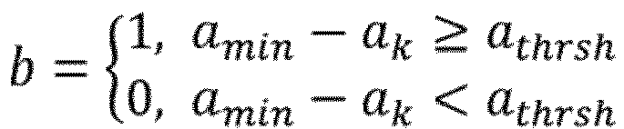 and 0 ≤ b ≤ 1, amin denotes a minimum accelerator opening degree of the vehicle, ak denotes an accelerator opening degree at the current time, athrsh denotes an accelerator opening degree change threshold value of the vehicle, and athrsh is a calibration value.
 - The method as claimed in claim 3, wherein in the step S25, in response to determining that the vehicle is in a high-speed acceleration driving condition, the control parameter factor b is calculated through the following formula:the control parameter factor b = max (bδ , bv , bsw , bcoast );and bδ denotes a steering wheel rotation angle control factor of the vehicle, 0≤bδ≤1, bv denotes a vehicle speed control parameter factor of the vehicle, 0≤bv≤1, bsw denotes a control parameter factor of the vehicle under a steering condition, bcoast denotes a slip control parameter factor of the vehicle, in response to determining that the vehicle is in a slip driving condition and performing anti-slip control, the slip control parameter factor bcoast is equal to 1, and in response to determining that the vehicle is in the slip driving condition and exiting anti-slip control, the slip control parameter factor bcoast is equal to 0.
- The method as claimed in claim 5, wherein the calculation formula of the steering wheel rotation angle control factor bδ of the vehicle is as follow:

- The method as claimed in claim 5, wherein the calculation formula of the vehicle speed control parameter factor bv of the vehicle is as follow:

- The method as claimed in claim 5, wherein the calculation formula of the control parameter factor bsw of the vehicle under the steering condition is as follow:

- The method as claimed in claim 1, wherein in response to determining that the main driving shaft is a rear axle, and the influence of the steering of the vehicle and the lateral deviation of the tire being considered, the speed vs, target of the main driving shaft is calculated through the following formula:
 and vm, F denotes an average value of the rotating speeds of the two wheels at the two ends of the front axle, and the unit of the rotating speed is m/s; λ0 denotes a target trackslip rate; θ denotes a front wheel rotation angle, and the unit of the front wheel rotation angle is rad; γ denotes the yaw rate of the vehicle, and the unit of the yaw rate is rad/s; and L denotes a wheelbase, and the unit of the wheelbase is m;in response to determining that the main driving shaft is a front axle, and the influence of the steering of the vehicle and the lateral deviation of the tire being considered, the speed vs, target of the main driving shaft is calculated through the following formula:
 and vm, R denotes an average value of the rotating speeds of the two wheels at the two ends of the rear axle, and the unit of the rotating speeds is m/s.
 - The method as claimed in claim 1, wherein the calculation formula of the minimum speed vmin of the vehicle is as follow:

- An electronic device, comprising:at least one processor; anda memory, configured to store at least one program; andin response to the at least one program is executed by the at least one processor, the at least one processor implements the anti-slip control method of transfer case as claimed in any one of claims 1-10.
- A computer-readable storage medium, wherein the computer-readable storage medium is configured to store a computer program, and in response to executed by a processor, the computer program implements the anti-slip control method of transfer case as claimed in any one of claims 1-10.
- The method as claimed in claim 8, wherein the calculation formula of the lateral acceleration control parameter factor bay is as follow:
- The method as claimed in claim 8, wherein the calculation formula of the yaw rate control parameter factor by is as follow:

- The method as claimed in claim 8, wherein the torque control parameter factor bT under the steering acceleration condition increases along with the increase of the driving torque of the driving shaft, the calculation formula of bT is as follow:

Applications Claiming Priority (2)
| Application Number | Priority Date | Filing Date | Title |
|---|---|---|---|
| CN202110378352.0A CN113060119B (en) | 2021-04-08 | 2021-04-08 | Anti-skid control method for transfer case |
| PCT/CN2022/085796 WO2022214074A1 (en) | 2021-04-08 | 2022-04-08 | Anti-skid control method for transfer case |
Publications (4)
| Publication Number | Publication Date |
|---|---|
| EP4227181A1 EP4227181A1 (en) | 2023-08-16 |
| EP4227181A4 EP4227181A4 (en) | 2024-04-03 |
| EP4227181C0 EP4227181C0 (en) | 2025-03-12 |
| EP4227181B1 true EP4227181B1 (en) | 2025-03-12 |
Family
ID=76566299
Family Applications (1)
| Application Number | Title | Priority Date | Filing Date |
|---|---|---|---|
| EP22784140.0A Active EP4227181B1 (en) | 2021-04-08 | 2022-04-08 | Anti-skid control method for transfer case |
Country Status (3)
| Country | Link |
|---|---|
| EP (1) | EP4227181B1 (en) |
| CN (1) | CN113060119B (en) |
| WO (1) | WO2022214074A1 (en) |
Families Citing this family (1)
| Publication number | Priority date | Publication date | Assignee | Title |
|---|---|---|---|---|
| CN113060119B (en) * | 2021-04-08 | 2022-04-12 | 中国第一汽车股份有限公司 | Anti-skid control method for transfer case |
Family Cites Families (27)
| Publication number | Priority date | Publication date | Assignee | Title |
|---|---|---|---|---|
| JP2964875B2 (en) * | 1994-07-19 | 1999-10-18 | 株式会社デンソー | Anti-skid control device |
| JP3908074B2 (en) * | 2002-04-08 | 2007-04-25 | アイシン精機株式会社 | Electric steering control device and vehicle anti-skid control device having the same |
| US7421328B2 (en) * | 2004-09-07 | 2008-09-02 | Advics Co., Ltd. | Vehicle slip state determination system and traveling state control system |
| JP4696224B2 (en) * | 2005-07-19 | 2011-06-08 | 三菱自動車工業株式会社 | Differential restriction control device for four-wheel drive vehicle |
| CN1883978B (en) * | 2006-06-28 | 2013-07-10 | 周殿玺 | Antiskid transfer case |
| JP2010516556A (en) * | 2007-01-25 | 2010-05-20 | 本田技研工業株式会社 | Vehicle system control method for improving vehicle stability |
| JP4955482B2 (en) * | 2007-08-07 | 2012-06-20 | 日産自動車株式会社 | Driving force distribution control device for four-wheel drive vehicles |
| JP5286921B2 (en) * | 2008-05-12 | 2013-09-11 | 日産自動車株式会社 | Vibration suppression control device for vehicle |
| DE102009005378C5 (en) * | 2008-10-13 | 2018-06-21 | Magna powertrain gmbh & co kg | Powertrain for a motor vehicle |
| JP5391456B2 (en) * | 2009-11-25 | 2014-01-15 | 公益財団法人鉄道総合技術研究所 | Electric motor control method and electric motor control device |
| JP5736673B2 (en) * | 2010-06-07 | 2015-06-17 | 日産自動車株式会社 | Braking force coordination controller for compound brake |
| US9199639B2 (en) * | 2010-09-28 | 2015-12-01 | Hitachi Automotive Systems, Ltd. | Motion control system of vehicle |
| GB2486177A (en) * | 2010-12-02 | 2012-06-13 | Land Rover Uk Ltd | Traction control method that allows for processing time delays |
| JP5835583B2 (en) * | 2012-04-27 | 2015-12-24 | 三菱自動車工業株式会社 | Driving force control device for electric vehicle |
| CN102717786B (en) * | 2012-06-11 | 2015-01-14 | 上海三一重机有限公司 | Control method for pavement self-adaptive antiskid antilock of electrically driven mine car |
| DE112013007223T5 (en) * | 2013-07-11 | 2016-04-28 | Toyota Jidosha Kabushiki Kaisha | Vehicle control system |
| JP6162762B2 (en) * | 2015-08-27 | 2017-07-12 | 株式会社Subaru | Vehicle control apparatus and vehicle control method |
| CN106553541B (en) * | 2015-09-25 | 2019-02-01 | 长城汽车股份有限公司 | Vehicle and transfer case |
| JP6776502B2 (en) * | 2016-09-23 | 2020-10-28 | 日立オートモティブシステムズ株式会社 | Electric vehicle controls, control methods and control systems |
| JP6569646B2 (en) * | 2016-11-11 | 2019-09-04 | 株式会社アドヴィックス | Anti-skid control device for vehicle |
| CN109927704B (en) * | 2018-03-06 | 2020-06-26 | 万向钱潮股份有限公司 | Control method for preventing automobile wheel from driving to slide and rotate |
| WO2021029193A1 (en) * | 2019-08-15 | 2021-02-18 | 日本電産株式会社 | Vibration damping control device, and vibration damping control method |
| CN111645533A (en) * | 2019-12-30 | 2020-09-11 | 联合汽车电子有限公司 | New energy automobile driving method |
| CN110979026B (en) * | 2019-12-31 | 2021-08-13 | 厦门金龙联合汽车工业有限公司 | A torque distribution method for distributed driving buses based on real-time road conditions |
| CN112026535A (en) * | 2020-09-07 | 2020-12-04 | 中国第一汽车股份有限公司 | Control method and control system of distributed four-wheel-drive electric vehicle |
| CN112455447B (en) * | 2021-01-28 | 2021-05-14 | 天津所托瑞安汽车科技有限公司 | Vehicle antiskid control method and device, electronic equipment and medium |
| CN113060119B (en) * | 2021-04-08 | 2022-04-12 | 中国第一汽车股份有限公司 | Anti-skid control method for transfer case |
-
2021
- 2021-04-08 CN CN202110378352.0A patent/CN113060119B/en active Active
-
2022
- 2022-04-08 EP EP22784140.0A patent/EP4227181B1/en active Active
- 2022-04-08 WO PCT/CN2022/085796 patent/WO2022214074A1/en not_active Ceased
Also Published As
| Publication number | Publication date |
|---|---|
| EP4227181A4 (en) | 2024-04-03 |
| EP4227181A1 (en) | 2023-08-16 |
| EP4227181C0 (en) | 2025-03-12 |
| CN113060119B (en) | 2022-04-12 |
| WO2022214074A1 (en) | 2022-10-13 |
| CN113060119A (en) | 2021-07-02 |
Similar Documents
| Publication | Publication Date | Title |
|---|---|---|
| CN113479208B (en) | Automobile starting control method, device, equipment and storage medium | |
| CN115303081B (en) | A torque calculation method, device, equipment and medium for distributed electric vehicles | |
| CN114506333B (en) | Road adhesion coefficient determination method, device and equipment and automatic driving vehicle | |
| EP4227181B1 (en) | Anti-skid control method for transfer case | |
| WO2023029711A1 (en) | Chassis domain control method under high-speed working condition, and related apparatus | |
| EP4617148A1 (en) | Method and system for controlling front and rear wheels, and electronic device, storage medium and vehicle | |
| CN115431955A (en) | Vehicle control method, device, vehicle and storage medium | |
| CN116653635A (en) | A motor torque distribution method and device | |
| CN119160008B (en) | Torque control method, device, equipment and storage medium for four-wheel drive vehicle | |
| US20250206291A1 (en) | Vehicle control unit, motor control unit, and related device | |
| CN115675445A (en) | Vehicle control method, system, device, storage medium and vehicle based on rear wheel | |
| CN118651210A (en) | Vehicle slip rate setting method, device, equipment and storage medium | |
| US20200039504A1 (en) | Method and Apparatus for Controlling a Vehicle | |
| CN119160007A (en) | Torque control method, device, equipment and readable storage medium based on slip ratio | |
| CN115366693A (en) | A driving control method, device, electronic device and storage medium | |
| CN119142336A (en) | Vehicle climbing control method, device, equipment and storage medium | |
| CN117002509A (en) | Torque distribution methods, devices, computer equipment and storage media | |
| CN116811840A (en) | Control method for rapidly calculating stability of electric heavy truck | |
| CN117698746A (en) | Vehicle gradient calculating method and device, electronic equipment and storage medium | |
| CN119189702B (en) | Torque control method, device, equipment and storage medium of distributed four-wheel drive motor | |
| CN116101264A (en) | A vehicle stability control method, system, electronic device and storage medium | |
| CN121316592A (en) | Methods, systems, products and media for energy recovery and distribution in four-wheel drive new energy vehicles | |
| CN120307899A (en) | Vehicle control method, vehicle and storage medium | |
| CN120517218A (en) | Vehicle driving control method and controller | |
| CN118722656A (en) | Vehicle energy recovery adaptive control method, device, equipment and storage medium |
Legal Events
| Date | Code | Title | Description |
|---|---|---|---|
| STAA | Information on the status of an ep patent application or granted ep patent |
Free format text: STATUS: THE INTERNATIONAL PUBLICATION HAS BEEN MADE |
|
| PUAI | Public reference made under article 153(3) epc to a published international application that has entered the european phase |
Free format text: ORIGINAL CODE: 0009012 |
|
| STAA | Information on the status of an ep patent application or granted ep patent |
Free format text: STATUS: REQUEST FOR EXAMINATION WAS MADE |
|
| 17P | Request for examination filed |
Effective date: 20230509 |
|
| AK | Designated contracting states |
Kind code of ref document: A1 Designated state(s): AL AT BE BG CH CY CZ DE DK EE ES FI FR GB GR HR HU IE IS IT LI LT LU LV MC MK MT NL NO PL PT RO RS SE SI SK SM TR |
|
| A4 | Supplementary search report drawn up and despatched |
Effective date: 20240304 |
|
| RIC1 | Information provided on ipc code assigned before grant |
Ipc: B60W 10/119 20120101ALI20240227BHEP Ipc: B60W 10/30 20060101ALI20240227BHEP Ipc: B60W 40/00 20060101AFI20240227BHEP |
|
| DAV | Request for validation of the european patent (deleted) | ||
| DAX | Request for extension of the european patent (deleted) | ||
| GRAP | Despatch of communication of intention to grant a patent |
Free format text: ORIGINAL CODE: EPIDOSNIGR1 |
|
| STAA | Information on the status of an ep patent application or granted ep patent |
Free format text: STATUS: GRANT OF PATENT IS INTENDED |
|
| INTG | Intention to grant announced |
Effective date: 20241104 |
|
| GRAS | Grant fee paid |
Free format text: ORIGINAL CODE: EPIDOSNIGR3 |
|
| GRAA | (expected) grant |
Free format text: ORIGINAL CODE: 0009210 |
|
| STAA | Information on the status of an ep patent application or granted ep patent |
Free format text: STATUS: THE PATENT HAS BEEN GRANTED |
|
| AK | Designated contracting states |
Kind code of ref document: B1 Designated state(s): AL AT BE BG CH CY CZ DE DK EE ES FI FR GB GR HR HU IE IS IT LI LT LU LV MC MK MT NL NO PL PT RO RS SE SI SK SM TR |
|
| REG | Reference to a national code |
Ref country code: GB Ref legal event code: FG4D |
|
| REG | Reference to a national code |
Ref country code: CH Ref legal event code: EP |
|
| REG | Reference to a national code |
Ref country code: DE Ref legal event code: R096 Ref document number: 602022011797 Country of ref document: DE |
|
| REG | Reference to a national code |
Ref country code: IE Ref legal event code: FG4D |
|
| U01 | Request for unitary effect filed |
Effective date: 20250407 |
|
| U07 | Unitary effect registered |
Designated state(s): AT BE BG DE DK EE FI FR IT LT LU LV MT NL PT RO SE SI Effective date: 20250411 |
|
| U20 | Renewal fee for the european patent with unitary effect paid |
Year of fee payment: 4 Effective date: 20250520 |
|
| PG25 | Lapsed in a contracting state [announced via postgrant information from national office to epo] |
Ref country code: RS Free format text: LAPSE BECAUSE OF FAILURE TO SUBMIT A TRANSLATION OF THE DESCRIPTION OR TO PAY THE FEE WITHIN THE PRESCRIBED TIME-LIMIT Effective date: 20250612 |
|
| PG25 | Lapsed in a contracting state [announced via postgrant information from national office to epo] |
Ref country code: ES Free format text: LAPSE BECAUSE OF FAILURE TO SUBMIT A TRANSLATION OF THE DESCRIPTION OR TO PAY THE FEE WITHIN THE PRESCRIBED TIME-LIMIT Effective date: 20250312 |
|
| PG25 | Lapsed in a contracting state [announced via postgrant information from national office to epo] |
Ref country code: NO Free format text: LAPSE BECAUSE OF FAILURE TO SUBMIT A TRANSLATION OF THE DESCRIPTION OR TO PAY THE FEE WITHIN THE PRESCRIBED TIME-LIMIT Effective date: 20250612 |
|
| PG25 | Lapsed in a contracting state [announced via postgrant information from national office to epo] |
Ref country code: HR Free format text: LAPSE BECAUSE OF FAILURE TO SUBMIT A TRANSLATION OF THE DESCRIPTION OR TO PAY THE FEE WITHIN THE PRESCRIBED TIME-LIMIT Effective date: 20250312 |
|
| PG25 | Lapsed in a contracting state [announced via postgrant information from national office to epo] |
Ref country code: GR Free format text: LAPSE BECAUSE OF FAILURE TO SUBMIT A TRANSLATION OF THE DESCRIPTION OR TO PAY THE FEE WITHIN THE PRESCRIBED TIME-LIMIT Effective date: 20250613 |
|
| PG25 | Lapsed in a contracting state [announced via postgrant information from national office to epo] |
Ref country code: SM Free format text: LAPSE BECAUSE OF FAILURE TO SUBMIT A TRANSLATION OF THE DESCRIPTION OR TO PAY THE FEE WITHIN THE PRESCRIBED TIME-LIMIT Effective date: 20250312 |
|
| PG25 | Lapsed in a contracting state [announced via postgrant information from national office to epo] |
Ref country code: PL Free format text: LAPSE BECAUSE OF FAILURE TO SUBMIT A TRANSLATION OF THE DESCRIPTION OR TO PAY THE FEE WITHIN THE PRESCRIBED TIME-LIMIT Effective date: 20250312 |
|
| PG25 | Lapsed in a contracting state [announced via postgrant information from national office to epo] |
Ref country code: CZ Free format text: LAPSE BECAUSE OF FAILURE TO SUBMIT A TRANSLATION OF THE DESCRIPTION OR TO PAY THE FEE WITHIN THE PRESCRIBED TIME-LIMIT Effective date: 20250312 |
|
| PG25 | Lapsed in a contracting state [announced via postgrant information from national office to epo] |
Ref country code: SK Free format text: LAPSE BECAUSE OF FAILURE TO SUBMIT A TRANSLATION OF THE DESCRIPTION OR TO PAY THE FEE WITHIN THE PRESCRIBED TIME-LIMIT Effective date: 20250312 |
|
| PG25 | Lapsed in a contracting state [announced via postgrant information from national office to epo] |
Ref country code: IS Free format text: LAPSE BECAUSE OF FAILURE TO SUBMIT A TRANSLATION OF THE DESCRIPTION OR TO PAY THE FEE WITHIN THE PRESCRIBED TIME-LIMIT Effective date: 20250712 |
|
| REG | Reference to a national code |
Ref country code: CH Ref legal event code: H13 Free format text: ST27 STATUS EVENT CODE: U-0-0-H10-H13 (AS PROVIDED BY THE NATIONAL OFFICE) Effective date: 20251125 |
|
| PG25 | Lapsed in a contracting state [announced via postgrant information from national office to epo] |
Ref country code: MC Free format text: LAPSE BECAUSE OF FAILURE TO SUBMIT A TRANSLATION OF THE DESCRIPTION OR TO PAY THE FEE WITHIN THE PRESCRIBED TIME-LIMIT Effective date: 20250312 |
|
| PLBE | No opposition filed within time limit |
Free format text: ORIGINAL CODE: 0009261 |
|
| STAA | Information on the status of an ep patent application or granted ep patent |
Free format text: STATUS: NO OPPOSITION FILED WITHIN TIME LIMIT |
|
| PG25 | Lapsed in a contracting state [announced via postgrant information from national office to epo] |
Ref country code: CH Free format text: LAPSE BECAUSE OF NON-PAYMENT OF DUE FEES Effective date: 20250430 |
|
| REG | Reference to a national code |
Ref country code: CH Ref legal event code: L10 Free format text: ST27 STATUS EVENT CODE: U-0-0-L10-L00 (AS PROVIDED BY THE NATIONAL OFFICE) Effective date: 20260121 |
|
| 26N | No opposition filed |
Effective date: 20251215 |
|
| PG25 | Lapsed in a contracting state [announced via postgrant information from national office to epo] |
Ref country code: IE Free format text: LAPSE BECAUSE OF NON-PAYMENT OF DUE FEES Effective date: 20250408 |