EP4227153A1 - Seat device for vehicle and control method for seat device for vehicle - Google Patents
Seat device for vehicle and control method for seat device for vehicle Download PDFInfo
- Publication number
- EP4227153A1 EP4227153A1 EP20957556.2A EP20957556A EP4227153A1 EP 4227153 A1 EP4227153 A1 EP 4227153A1 EP 20957556 A EP20957556 A EP 20957556A EP 4227153 A1 EP4227153 A1 EP 4227153A1
- Authority
- EP
- European Patent Office
- Prior art keywords
- headrest
- vehicle
- occupant
- head
- width direction
- Prior art date
- Legal status (The legal status is an assumption and is not a legal conclusion. Google has not performed a legal analysis and makes no representation as to the accuracy of the status listed.)
- Granted
Links
Images






Classifications
-
- B—PERFORMING OPERATIONS; TRANSPORTING
- B60—VEHICLES IN GENERAL
- B60N—SEATS SPECIALLY ADAPTED FOR VEHICLES; VEHICLE PASSENGER ACCOMMODATION NOT OTHERWISE PROVIDED FOR
- B60N2/00—Seats specially adapted for vehicles; Arrangement or mounting of seats in vehicles
- B60N2/80—Head-rests
- B60N2/806—Head-rests movable or adjustable
- B60N2/868—Head-rests movable or adjustable providing a lateral movement parallel to the occupant's shoulder line
-
- B—PERFORMING OPERATIONS; TRANSPORTING
- B60—VEHICLES IN GENERAL
- B60N—SEATS SPECIALLY ADAPTED FOR VEHICLES; VEHICLE PASSENGER ACCOMMODATION NOT OTHERWISE PROVIDED FOR
- B60N2/00—Seats specially adapted for vehicles; Arrangement or mounting of seats in vehicles
- B60N2/80—Head-rests
- B60N2/888—Head-rests with arrangements for protecting against abnormal g-forces, e.g. by displacement of the head-rest
-
- B—PERFORMING OPERATIONS; TRANSPORTING
- B60—VEHICLES IN GENERAL
- B60N—SEATS SPECIALLY ADAPTED FOR VEHICLES; VEHICLE PASSENGER ACCOMMODATION NOT OTHERWISE PROVIDED FOR
- B60N2/00—Seats specially adapted for vehicles; Arrangement or mounting of seats in vehicles
- B60N2/002—Seats provided with an occupancy detection means mounted therein or thereon
- B60N2/0021—Seats provided with an occupancy detection means mounted therein or thereon characterised by the type of sensor or measurement
- B60N2/0024—Seats provided with an occupancy detection means mounted therein or thereon characterised by the type of sensor or measurement for identifying, categorising or investigation of the occupant or object on the seat
- B60N2/0027—Seats provided with an occupancy detection means mounted therein or thereon characterised by the type of sensor or measurement for identifying, categorising or investigation of the occupant or object on the seat for detecting the position of the occupant or of occupant's body part
- B60N2/0028—Seats provided with an occupancy detection means mounted therein or thereon characterised by the type of sensor or measurement for identifying, categorising or investigation of the occupant or object on the seat for detecting the position of the occupant or of occupant's body part of a body part, e.g. of an arm or a leg
-
- B—PERFORMING OPERATIONS; TRANSPORTING
- B60—VEHICLES IN GENERAL
- B60N—SEATS SPECIALLY ADAPTED FOR VEHICLES; VEHICLE PASSENGER ACCOMMODATION NOT OTHERWISE PROVIDED FOR
- B60N2/00—Seats specially adapted for vehicles; Arrangement or mounting of seats in vehicles
- B60N2/02—Seats specially adapted for vehicles; Arrangement or mounting of seats in vehicles the seat or part thereof being movable, e.g. adjustable
- B60N2/0224—Non-manual adjustments, e.g. with electrical operation
- B60N2/0244—Non-manual adjustments, e.g. with electrical operation with logic circuits
- B60N2/026—Non-manual adjustments, e.g. with electrical operation with logic circuits varying hardness or support of upholstery, e.g. for tuning seat comfort when driving curved roads
-
- B—PERFORMING OPERATIONS; TRANSPORTING
- B60—VEHICLES IN GENERAL
- B60N—SEATS SPECIALLY ADAPTED FOR VEHICLES; VEHICLE PASSENGER ACCOMMODATION NOT OTHERWISE PROVIDED FOR
- B60N2/00—Seats specially adapted for vehicles; Arrangement or mounting of seats in vehicles
- B60N2/02—Seats specially adapted for vehicles; Arrangement or mounting of seats in vehicles the seat or part thereof being movable, e.g. adjustable
- B60N2/0224—Non-manual adjustments, e.g. with electrical operation
- B60N2/0244—Non-manual adjustments, e.g. with electrical operation with logic circuits
- B60N2/0268—Non-manual adjustments, e.g. with electrical operation with logic circuits using sensors or detectors for adapting the seat or seat part, e.g. to the position of an occupant
-
- B—PERFORMING OPERATIONS; TRANSPORTING
- B60—VEHICLES IN GENERAL
- B60N—SEATS SPECIALLY ADAPTED FOR VEHICLES; VEHICLE PASSENGER ACCOMMODATION NOT OTHERWISE PROVIDED FOR
- B60N2/00—Seats specially adapted for vehicles; Arrangement or mounting of seats in vehicles
- B60N2/80—Head-rests
- B60N2/879—Head-rests with additional features not related to head-rest positioning, e.g. heating or cooling devices or loudspeakers
-
- B—PERFORMING OPERATIONS; TRANSPORTING
- B60—VEHICLES IN GENERAL
- B60N—SEATS SPECIALLY ADAPTED FOR VEHICLES; VEHICLE PASSENGER ACCOMMODATION NOT OTHERWISE PROVIDED FOR
- B60N2/00—Seats specially adapted for vehicles; Arrangement or mounting of seats in vehicles
- B60N2/80—Head-rests
- B60N2/885—Head-rests provided with side-rests
-
- B—PERFORMING OPERATIONS; TRANSPORTING
- B60—VEHICLES IN GENERAL
- B60N—SEATS SPECIALLY ADAPTED FOR VEHICLES; VEHICLE PASSENGER ACCOMMODATION NOT OTHERWISE PROVIDED FOR
- B60N2/00—Seats specially adapted for vehicles; Arrangement or mounting of seats in vehicles
- B60N2/80—Head-rests
- B60N2/897—Head-rests with sleeves located in the back-rest for guiding the rods of the head-rest
-
- B—PERFORMING OPERATIONS; TRANSPORTING
- B60—VEHICLES IN GENERAL
- B60N—SEATS SPECIALLY ADAPTED FOR VEHICLES; VEHICLE PASSENGER ACCOMMODATION NOT OTHERWISE PROVIDED FOR
- B60N2/00—Seats specially adapted for vehicles; Arrangement or mounting of seats in vehicles
- B60N2/90—Details or parts not otherwise provided for
- B60N2/914—Hydro-pneumatic adjustments of the shape
-
- B—PERFORMING OPERATIONS; TRANSPORTING
- B60—VEHICLES IN GENERAL
- B60N—SEATS SPECIALLY ADAPTED FOR VEHICLES; VEHICLE PASSENGER ACCOMMODATION NOT OTHERWISE PROVIDED FOR
- B60N2210/00—Sensor types, e.g. for passenger detection systems or for controlling seats
- B60N2210/10—Field detection presence sensors
- B60N2210/16—Electromagnetic waves
- B60N2210/22—Optical; Photoelectric; Lidar [Light Detection and Ranging]
- B60N2210/24—Cameras
-
- B—PERFORMING OPERATIONS; TRANSPORTING
- B60—VEHICLES IN GENERAL
- B60N—SEATS SPECIALLY ADAPTED FOR VEHICLES; VEHICLE PASSENGER ACCOMMODATION NOT OTHERWISE PROVIDED FOR
- B60N2210/00—Sensor types, e.g. for passenger detection systems or for controlling seats
- B60N2210/40—Force or pressure sensors
Definitions
- the present invention relates to a vehicle seat device and a control method for a vehicle seat device.
- JP 2015-39913 A discloses a support rigidity control device (vehicle seat device) in which a support rigidity in a left-right direction or a roll direction with respect to an upper body portion of an occupant seated on a vehicle seat is variable.
- a support rigidity control device vehicle seat device
- a high frequency component of a lateral acceleration of a vehicle increases, the support rigidity of the seat in the left-right direction or the roll direction is reduced, and a high frequency vibration component is absorbed with movement of a chest, so that the lateral acceleration of the vehicle transmitted to a head is reduced.
- the present invention has been made in view of the above problems, and an object of the present invention is to provide a vehicle seat device and a control method for a vehicle seat device which are capable of reducing discomfort of an occupant caused by a vibration in a vehicle width direction.
- a vehicle seat device that includes a headrest to support a head of an occupant seated on a vehicle seat.
- the vehicle seat device includes a rest operation adjustment mechanism provided on the headrest and to restrict or allow movement of the head of the occupant seated on the vehicle seat and a controller that controls the rest operation adjustment mechanism to allow the movement of the head of the occupant when a frequency of a vibration in a width direction of a vehicle is equal to or larger than a predetermined value.
- FIG. 1 is a schematic configuration diagram showing a main configuration of a vehicle seat device 100 according to a first embodiment.
- the vehicle seat device 100 is a device mounted on a vehicle or the like, and includes a vehicle seat 10 including a seat cushion 1, a seatback 2, a headrest 3, headrest stays 4, and the like, a lateral G sensor 5, a monitor camera 6, and a controller 7.
- the seat cushion 1 is a portion on which an occupant is seated, and is supported on a floor surface of a vehicle via a seat bracket (not shown) or the like so as to be movable in a front-rear direction of the vehicle.
- the occupant is not limited to a driver, and includes a person who is seated on a passenger seat, a rear seat, or the like.
- the seatback 2 is a backrest that supports a back of the occupant seated on the vehicle seat 10 (seat cushion 1), and is erected from a rear end of the seat cushion 1.
- the seatback 2 can rise and fall with respect to the seat cushion 1 via a hinge mechanism (not shown) or the like.
- Stay holders 21 are provided on an upper end of the seatback 2, which have insertion holes into which the headrest stays 4 to be described later are inserted, respectively.
- the stay holder 21 supports the headrest stay 4 inserted into the insertion hole.
- the headrest 3 is connected to the upper end of the seatback 2 via the headrest stays 4, and supports a head of the occupant seated on the vehicle seat 10 (seat cushion 1).
- the headrest stays 4 extend downward from the vicinities of both ends of a lower surface of the headrest 3, and are inserted into the insertion holes of the stay holders 21 provided on the seatback 2, respectively.
- the headrest 3 will be described in detail later.
- the lateral G sensor 5 detects a lateral acceleration (lateral G) acting on the vehicle.
- An installation location of the lateral G sensor 5 is not particularly limited as long as the lateral G sensor 5 can detect the lateral G, and the lateral G sensor 5 is installed, for example, at a leg portion (lower portion of the seat cushion 1) of the vehicle seat 10.
- Information on the lateral acceleration (lateral G) of the vehicle detected by the lateral G sensor 5 is transmitted to the controller 7.
- the monitor camera 6 is an imaging device that images states of the vehicle seat 10 and the occupant seated on the vehicle seat 10.
- An installation location of the monitor camera 6 is not particularly limited as long as the monitor camera 6 can image the states of the occupant and the vehicle seat 10, and the monitor camera 6 is installed, for example, on a vehicle interior side of a windshield of the vehicle.
- a plurality of monitor cameras 6 may be installed.
- Information imaged by the monitor camera 6 (imaging information) is transmitted to the controller 7.
- the controller 7 includes a frequency calculation unit 71 that calculates a frequency f of a vibration in a lateral direction of the vehicle, a headrest shape control unit 72 that controls a head contact area adjustment mechanism B13 (see FIG. 4 ) of the headrest 3 to be described later, and the like.
- the frequency calculation unit 71 calculates the frequency f in the lateral direction (vehicle width direction) of the vehicle based on the information on the lateral acceleration (lateral G) of the vehicle detected by the lateral G sensor 5.
- the headrest shape control unit 72 will be described later.
- the controller 7 is implemented by a microcomputer including a central processing unit (CPU), a read-only memory (ROM), a random access memory (RAM), and an input/output interface (I/O interface).
- the controller 7 may be implemented by a plurality of microcomputers.
- the controller 7 executes a specific program to execute a process for controlling the entire vehicle seat device 100. For example, the controller 7 executes a rest operation control based on a frequency in a width direction of the vehicle to be described later.
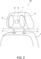
- FIG. 2 is a schematic configuration diagram showing the headrest 3 of the vehicle seat device 100 according to the first embodiment.
- the headrest 3 includes air chambers (rest operation adjustment mechanism, head contact area adjustment mechanism) 31, a pressure sensor 32, the headrest shape control unit 72, and the like inside the rest.
- the headrest stays 4 extend downward from the vicinities of both ends of the lower surface of the headrest 3, respectively.
- the headrest stay 4 is inserted into the insertion hole of the stay holder 21 provided on the upper end of the seatback 2.
- the stay holder 21 supports the headrest stay 4 inserted into the insertion hole, so that the headrest 3 is fixed to the seatback 2.
- the headrest stay 4 and the stay holder 21 are provided with a lock mechanism capable of switching between a locked state in which the headrest 3 is fixed to the seatback 2 and a lock released state in which the headrest 3 can be moved up and down with respect to the seatback 2.
- the lock mechanism is implemented by, for example, providing an engaging spring member on the headrest stay 4 and providing a groove with which the engaging spring member engages on the stay holder 21. In this case, for example, the headrest 3 can be moved up and down by tilting the headrest 3 to release the engagement between the engaging spring member of the headrest stay 4 and the groove of the stay holder 21 and sliding the headrest stay 4.
- the lock mechanism is not limited to the above, and any known lock mechanism may be used.
- the headrest stay 4 and the stay holder 21 are not essential components, and for example, the headrest 3 and the seatback 2 may be integrally formed without the headrest stay 4 interposed therebetween.
- the air chambers 31 are each a bag-shaped member that can hold gas (air) in a state of being accommodated therein, and are built in at both end portions of the headrest 3 in the vehicle width direction and at positions where temporal regions of the occupant seated on the vehicle seat 10 come, respectively.
- the air chamber 31 is connected to a gas supply source such as an inflator (not shown) provided inside or outside the headrest 3.
- a gas supply source such as an inflator (not shown) provided inside or outside the headrest 3.
- the air chambers 31 support the temporal regions of the occupant seated on the vehicle seat 10 from both left and right sides in a state in which the air chamber 31 is supplied with the gas and is expanded. That is, the air chamber 31 functions as a side support of the headrest 3 in an expanded state.
- a supply source for supplying gas (air) to the air chamber 31 is not limited to the inflator, and any known supply source may be used.
- the inflator (gas supply source) and the air chamber 31 are controlled by the headrest shape control unit 72 (controller 7).
- the pressure sensor 32 is a pressure sensitive sensor for detecting that the occupant is seated on the vehicle seat 10 and uses the headrest 3.
- the pressure sensor 32 is formed in a sheet shape, and is embedded in a surface of the headrest 3 on a front side of the vehicle.
- the pressure sensor 32 transmits a detection signal to the headrest shape control unit 72 (controller 7).
- the predetermined pressure is a pressure at which the use of the headrest 3 by the occupant is recognized, and the headrest shape control unit 72 (controller 7) determines that the headrest 3 is being used while receiving the detection signal from the pressure sensor 32.
- the headrest shape control unit 72 controls the inflator and the air chamber 31 to adjust a contact area between the headrest 3 and the head of the occupant. That is, the headrest shape control unit 72 supplies the gas from the inflator (gas supply source) to the air chamber 31, and causes the air chamber 31 to expand, thereby increasing the contact area between the headrest 3 and the head of the occupant. On the other hand, by discharging the gas in the air chamber 31 and causing the air chamber 31 to contract, the contact area between the headrest 3 and the head of the occupant is made smaller than when the air chamber 31 is expanded.
- the headrest shape control unit 72 receives the detection signal from the pressure sensor 32, the headrest shape control unit 72 causes the air chamber 31 to expand. Accordingly, the head of the occupant seated on the vehicle seat 10 is supported.
- FIG. 3 illustrates conceptual diagrams showing a contact area between the headrest 3 and the head of the occupant when the air chamber 31 is expanded and contracted, in which (a) is a diagram when the air chamber 31 is expanded, and (b) is a diagram when the air chamber 31 is contracted.
- the contact area between the headrest 3 and the head of the occupant is larger than when the air chamber 31 is contracted (b), and the temporal regions of the occupant seated on the vehicle seat 10 are supported by the headrest 3 from both left and right sides. Accordingly, movement of the head of the occupant is restricted.
- the air chamber 31 is contracted (b)
- the contact area between the headrest 3 and the head of the occupant is smaller than when the air chamber 31 is expanded (a), and the movement of the head of the occupant is easily allowed.
- the air chamber 31 is a head contact area adjustment mechanism that adjusts the contact area between the headrest 3 and the head of the occupant, and is a rest operation adjustment mechanism that restricts or allows the movement of the head of the occupant seated on the vehicle seat 10 by adjusting the contact area between the headrest 3 and the head of the occupant.
- the vehicle seat device 100 causes the air chamber 31 to expand and causes the air chamber 31 to function as the side support of the headrest 3, thereby restricting the movement of the head of the occupant in the vehicle width direction (lateral direction).
- a slow lateral swing low frequency vibration
- phases of vibrations of the head and a torso of the occupant are synchronized with each other, and a magnitude of movement of a viewpoint of the occupant is reduced. Therefore, discomfort of the occupant is reduced, and car sickness or the like is prevented.
- a small lateral swing high frequency vibration
- a phase difference ⁇ between the vibrations of the head and the torso of the occupant increases. That is, when the occupant uses the headrest 3, if the high frequency vibration (quick swing) occurs in the vehicle width direction, the head may interfere with the side support of the headrest 3, and the quick swing of the head may be aggravated.
- the aggravation of the quick swing of the head may cause the viewpoint of the occupant to become unsteady, cause the discomfort to the occupant, and cause the car sickness or the like.
- the vehicle seat device 100 is configured to allow the movement of the head of the occupant when the frequency f of the vibration in the width direction of the vehicle is equal to or larger than a predetermined value f th . If the movement of the head of the occupant is allowed, an action of spinal reflex by the cervical spine of the occupant, which attempts to synchronize movements of the torso and the head when the high frequency vibration occurs, can be activated to some extent. Accordingly, even when a small lateral swing (high frequency vibration) occurs, the phases of the vibrations of the head and the torso of the occupant are synchronized with each other, and the magnitude of the movement of the viewpoint of the occupant is reduced, so that the discomfort of the occupant is prevented.
- a small lateral swing high frequency vibration
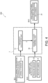
- FIG. 4 is a block diagram showing a functional configuration of the vehicle seat device 100 according to the first embodiment.
- the controller 7 includes the frequency calculation unit 71 and the headrest shape control unit 72.
- the detected lateral acceleration (lateral G) information of the vehicle is transmitted to the frequency calculation unit 71 from the lateral G sensor 5 which is a vehicle lateral acceleration measurement device B11 for detecting the lateral acceleration of the vehicle.
- the frequency calculation unit 71 calculates the frequency f of the vibration in the lateral direction (vehicle width direction) of the vehicle based on the received lateral acceleration (lateral G) information.
- the calculated frequency f of the vibration in the vehicle width direction is input to the headrest shape control unit 72.
- Headrest use determination information is transmitted to the headrest shape control unit 72 from a headrest use detection device B12 for detecting the use of the headrest 3 by the occupant.
- the headrest use detection device B12 is, for example, the pressure sensor 32 described above, and detection information of the pressure sensor 32 is transmitted to the headrest shape control unit 72 as the headrest use determination information.
- the frequency f of the vibration in the vehicle width direction of the vehicle calculated by the frequency calculation unit 71 is input to the headrest shape control unit 72.
- the headrest use detection device B12 is not limited to the pressure sensor 32, and may be any known device as long as the device can detect the use of the headrest 3 by the occupant.
- the monitor camera 6 may be used.
- the imaging information of the monitor camera 6 is transmitted to the headrest shape control unit 72, and the headrest shape control unit 72 determines whether the headrest 3 is used by the occupant based on the imaging information.
- the headrest shape control unit 72 determines, based on the headrest use determination information, whether the use of the headrest 3 by the occupant is recognized. When the use of the headrest 3 is recognized, the headrest shape control unit 72 determines whether the input frequency f of the vibration in the vehicle width direction of the vehicle is equal to or larger than the predetermined frequency f th , and controls the head contact area adjustment mechanism (rest operation adjustment mechanism) B13 based on the determination result.
- the predetermined frequency f th is a frequency at which, when the movement of the head of the occupant is restricted, the swing of the head is aggravated by the side support of the headrest 3, and a phase difference occurs between the vibrations of the head and the torso of the occupant to cause the discomfort to the occupant, and can be set in advance with an experiment or the like.
- the headrest shape control unit 72 sends a command to the head contact area adjustment mechanism (rest operation adjustment mechanism) B13 to increase the contact area between the headrest 3 and the head of the occupant.
- the air chamber 31, which is the head contact area adjustment mechanism B13 is expanded. Accordingly, the air chamber 31 protrudes from the headrest 3 toward the front of the vehicle, the contact area between the headrest 3 and the head of the occupant increases, and the movement of the head of the occupant is restricted.
- the headrest shape control unit 72 sends a command to the head contact area adjustment mechanism (rest operation adjustment mechanism) B13 to reduce the contact area between the headrest 3 and the head of the occupant.
- the air chamber 31, which is the head contact area adjustment mechanism B13 is contracted from the expanded state. Accordingly, the contact area between the headrest 3 and the head of the occupant is reduced, and the movement of the head of the occupant is allowed.
- the phases of the vibrations of the head and the torso of the occupant are synchronized with each other by the action of spinal reflex of the occupant.
- the frequency f of the vibration in the width direction of the vehicle is equal to or larger than the predetermined value f th , the contact area between the headrest 3 and the head of the occupant is reduced, so that the movement of the head of the occupant is allowed, and the phases of the vibrations of the head and the torso of the occupant are synchronized with each other. Accordingly, even when the high frequency vibration occurs in the vehicle width direction, the magnitude of the movement of the viewpoint of the occupant is reduced, and the discomfort of the occupant is prevented.
- FIG. 5 is a flowchart showing a rest operation control based on a frequency in the width direction of the vehicle executed by the vehicle seat device 100 according to the present embodiment. All of the following controls are repeatedly executed by the controller 7.
- the rest operation control based on the frequency in the width direction of the vehicle executed by the vehicle seat device 100 is started when the controller 7 receives an activation command of the vehicle seat device 100. For example, when an ON operation for switching a start key of the vehicle from OFF to ON is performed, an activation command is transmitted to the controller 7.
- step S101 the controller 7 acquires the information on the lateral acceleration (lateral G) of the vehicle detected by the lateral G sensor 5 and the imaging information captured by the monitor camera 6.
- the controller 7 receives a detection signal.
- step S102 the controller 7 determines whether the occupant is using the headrest 3. Whether the headrest 3 is used is determined based on whether the pressure sensor 32 detects that the predetermined pressure or more is input to the headrest 3, that is, whether the controller 7 receives the detection signal from the pressure sensor 32. When the use of the headrest 3 by the occupant is not recognized, the controller 7 ends the rest operation control based on the frequency in the width direction of the vehicle. On the other hand, when the pressure sensor 32 detects the pressure input to the headrest 3 and the use of the headrest 3 by the occupant is recognized, the controller 7 executes a process of step S103. As described above, whether the headrest 3 is used may be determined based on whether the use of the headrest 3 by the occupant is recognized, according to the imaging information captured by the monitor camera 6.
- step S103 the headrest shape control unit 72 (controller 7) causes the air chamber 31 to expand. Accordingly, the air chamber 31 protrudes toward the front of the vehicle and functions as the side support of the headrest 3, and the contact area between the headrest 3 and the head of the occupant increases.
- step S103 when the air chamber 31 is already in an expanded state, the headrest shape control unit 72 (controller 7) maintains the state.
- step S104 the controller 7 determines whether the frequency f of the vibration in the lateral direction (vehicle width direction) of the vehicle is equal to or larger than the predetermined frequency f th .
- the frequency f of the vibration in the vehicle width direction is calculated by the frequency calculation unit 71 of the controller 7 based on the information on the lateral acceleration (lateral G) of the vehicle detected by the lateral G sensor 5.
- the controller 7 ends the rest operation control based on the frequency in the width direction of the vehicle.
- the controller 7 executes a process of step S105.
- step S105 the headrest shape control unit 72 (controller 7) causes the air chamber 31 to contract toward the rear of the vehicle. Accordingly, the contact area between the headrest 3 and the head of the occupant is reduced, and the movement of the head of the occupant is allowed. As the movement of the head is allowed, the phases of the vibrations of the head and the torso of the occupant are synchronized with each other by the action of spinal reflex of the occupant.
- the controller 7 executes a process of step S106.
- step S105 when the air chamber 31 is already in a contracted state, the headrest shape control unit 72 (controller 7) maintains the state.
- step S106 the headrest shape control unit 72 (controller 7) determines again whether the frequency f of the vibration in the lateral direction (vehicle width direction) of the vehicle is equal to or larger than the predetermined frequency f th .
- a determination procedure is the same as in step S104.
- the headrest shape control unit 72 (controller 7) repeats the process of step S106 while maintaining the contracted state of the air chamber 31 until the frequency f of the vibration in the vehicle width direction is smaller than the predetermined frequency f th .
- the controller 7 executes a process of step S107.
- step S107 the headrest shape control unit 72 (controller 7) causes the air chamber 31 to expand to increase the contact area between the headrest 3 and the head of the occupant.
- the controller 7 ends the rest operation control based on the frequency in the width direction of the vehicle.
- the vehicle seat device 100 includes the rest operation adjustment mechanism (air chamber 31) provided on the headrest 3 and configured to restrict or allow the movement of the head of the occupant seated on the vehicle seat 10, and the headrest shape control unit 72 (controller 7).
- the headrest shape control unit 72 controls the rest operation adjustment mechanism (air chamber 31) to allow the movement of the head of the occupant when the frequency f of the vibration in the width direction of the vehicle is equal to or larger than the predetermined value f th .
- the headrest shape control unit 72 controls the head contact area adjustment mechanism B13 (air chamber 31) to reduce the contact area between the headrest 3 and the head of the occupant. Accordingly, when the frequency f of the vibration in the width direction of the vehicle is equal to or larger than the predetermined value f th , the movement of the head of the occupant is allowed.
- the phases of the vibrations of the head and the torso of the occupant can be synchronized with each other, and the magnitude of the movement of the viewpoint of the occupant is reduced, so that the discomfort of the occupant is prevented.
- the vehicle seat device 100 includes the air chambers 31 that are built in the headrest 3 and are expandable and contractible in the front-rear direction of the vehicle at the positions where the temporal regions of the occupant seated on the vehicle seat 10 come, respectively.
- the headrest shape control unit 72 (controller 7) causes the air chamber 31 to expand to reduce the contact area between the headrest 3 and the head of the occupant. Accordingly, when the frequency f of the vibration in the width direction of the vehicle is equal to or larger than the predetermined value f th , the movement of the head of the occupant is allowed.
- the phases of the vibrations of the head and the torso of the occupant can be synchronized with each other, and the magnitude of the movement of the viewpoint of the occupant is reduced, so that the discomfort of the occupant is prevented.
- the air chamber 31 is used as the head contact area adjustment mechanism B13 that adjusts the contact area between the headrest 3 and the head of the occupant, but the head contact area adjustment mechanism B13 is not necessarily limited to the air chamber 31 as long as the contact area between the headrest 3 and the head of the occupant can be adjusted.
- the head contact area adjustment mechanism B13 may be actuators that are built in the headrest 3 and are expandable and contractible in the front-rear direction of the vehicle at the positions where the temporal regions of the occupant seated on the vehicle seat 10 come, respectively.
- the headrest shape control unit 72 causes the actuators to expand toward the front of the vehicle.
- the headrest shape control unit 72 causes the actuators to contract toward the rear of the vehicle. Accordingly, when the frequency f of the vibration in the width direction of the vehicle is equal to or larger than the predetermined value f th , the contact area between the headrest 3 and the head of the occupant is reduced, and the movement of the head of the occupant is allowed.
- the frequency f of the vibration in the width direction of the vehicle is equal to or larger than the predetermined value f th , the movement of the head of the occupant is allowed by reducing the contact area between the headrest 3 and the head of the occupant. That is, the contact area between the headrest 3 and the head of the occupant is changed in two steps of large and small values using the predetermined value f th as a threshold value, but the present invention is not necessarily limited thereto.
- a size of the contact area between the headrest 3 and the head of the occupant may be changed in multiple stages in accordance with a magnitude of the frequency f of the vibration in the vehicle width direction, or the size of the contact area between the headrest 3 and the head of the occupant may be continuously changed in accordance with the magnitude of the frequency f of the vibration in the vehicle width direction.
- a vehicle seat device 100' according to a modification of the first embodiment will be described with reference to FIGS. 6 and 7 .
- the present modification is different from the first embodiment in that whether the frequency f of a vibration in a vehicle width direction is equal to or larger than the predetermined frequency f th is determined based on a phase difference ⁇ between vibrations of a head and a torso of an occupant in the vehicle width direction.
- the same elements as those in the first embodiment are denoted by the same reference numerals, and the description thereof will be omitted.
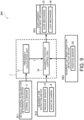
- FIG. 6 is a block diagram showing a functional configuration of the vehicle seat device 100' according to the modification of the first embodiment.
- the controller 7 includes a phase difference calculation unit 73 and the headrest shape control unit 72.
- Imaging information of the monitor camera 6 which is an occupant body behavior detection unit B11' that detects a behavior of a body of the occupant seated on the vehicle seat 10 is transmitted to the phase difference calculation unit 73.
- the phase difference calculation unit 73 calculates, based on the received imaging information of the monitor camera 6, the phase difference ⁇ between the vibration of the head of the occupant seated on the vehicle seat 10 in a width direction of a vehicle and the vibration of the torso of the occupant in the width direction of the vehicle.
- Information (phase difference information) on the calculated phase difference ⁇ between the vibrations of the head and the torso of the occupant is input to the headrest shape control unit 72.
- Headrest use determination information from the headrest use detection device B12 that detects the use of the headrest 3 by the occupant, and the phase difference information from the phase difference calculation unit 73 are input to the headrest shape control unit 72.
- the headrest shape control unit 72 determines, based on the headrest use determination information, whether the use of the headrest 3 by the occupant is recognized. When the use of the headrest 3 is recognized, the headrest shape control unit 72 determines, based on the phase difference information, whether the phase difference ⁇ between the vibrations of the head and the torso of the occupant is equal to or larger than a predetermined value ⁇ th .
- the predetermined value ⁇ th is a phase difference between the vibrations of the head and the torso of the occupant occurring when the frequency f of the vibration in the vehicle width direction is the predetermined frequency f th .
- the head when the occupant uses the headrest 3, if a high frequency vibration (quick swing) occurs in the vehicle width direction, the head interferes with a side support of the headrest 3, and the phase difference ⁇ between the vibrations of the head and the torso of the occupant increases.
- the phase difference ⁇ between the vibrations of the head and the torso of the occupant increases as the frequency f of the vibration in the vehicle width direction increases. Therefore, the value ⁇ th of the phase difference generated when the frequency f of the vibration in the vehicle width direction is the predetermined frequency f th can be set in advance with an experiment or the like.
- the headrest shape control unit 72 determines that the frequency f of the vibration in the vehicle width direction is smaller than the predetermined value f th , and increases the contact area between the headrest 3 and the head of the occupant. That is, the headrest shape control unit 72 sends a command to the head contact area adjustment mechanism (rest operation adjustment mechanism) B13 to cause the air chamber 31 which is the head contact area adjustment mechanism B13 to expand, thereby increasing a contact area between the headrest 3 and the head of the occupant. Accordingly, movement of the head of the occupant is restricted.
- the headrest shape control unit 72 determines that the frequency f of the vibration in the vehicle width direction is equal to or larger than the predetermined value f th , and reduces the contact area between the headrest 3 and the head of the occupant. That is, the headrest shape control unit 72 sends a command to the head contact area adjustment mechanism (rest operation adjustment mechanism) B13 to cause the air chamber 31 which is the head contact area adjustment mechanism B13 to contract from an expanded state, thereby reducing the contact area between the headrest 3 and the head of the occupant. Accordingly, the movement of the head of the occupant is allowed.
- the frequency f of the vibration in the vehicle width direction is determined to be equal to or larger than the predetermined value f th , the contact area between the headrest 3 and the head of the occupant is reduced, and the movement of the head of the occupant is allowed.
- FIG. 7 is a flowchart showing a rest operation control based on a frequency in the width direction of the vehicle executed by the vehicle seat device 100' according to the modification of the first embodiment. As in the first embodiment, all of the following controls are repeatedly executed by the controller 7.
- Steps S101 to S103 are the same as those in the first embodiment, and thus the description thereof will be omitted.
- step S104' the controller 7 determines whether the frequency f of the vibration in the vehicle width direction is equal to or larger than the predetermined frequency f th based on the phase difference ⁇ between the vibrations of the head and the torso of the occupant in the width direction of the vehicle. That is, the controller 7 determines, based on the imaging information captured by the monitor camera 6, whether the phase difference ⁇ between the vibrations of the head and the torso of the occupant in the width direction of the vehicle calculated by the phase difference calculation unit 73 is equal to or larger than the predetermined value ⁇ th .
- the controller 7 determines that the frequency f of the vibration in the vehicle width direction is smaller than the predetermined frequency f th , and ends the rest operation control based on the frequency in the width direction of the vehicle.
- the controller 7 determines that the frequency f of the vibration in the vehicle width direction is equal to or larger than the predetermined value f th , and executes the process of step S105.
- step S105 the headrest shape control unit 72 (controller 7) causes the air chamber 31 to contract toward the rear of the vehicle. Accordingly, the contact area between the headrest 3 and the head of the occupant is reduced, and the movement of the head of the occupant is allowed.
- step S105 when the air chamber 31 is already in a contracted state, the headrest shape control unit 72 (controller 7) maintains the state.
- step S106' the headrest shape control unit 72 (controller 7) determines again whether the frequency f of the vibration in the lateral direction (vehicle width direction) of the vehicle is equal to or larger than the predetermined frequency f th based on whether the phase difference ⁇ between the vibrations of the head and the torso of the occupant is equal to or larger than the predetermined value ⁇ th .
- a determination procedure is the same as in step S104', and the determination is executed based on the phase difference ⁇ between the vibrations of the head and the torso of the occupant in the width direction of the vehicle.
- the controller 7 repeats the process of step S106 while maintaining the contracted state of the air chamber 31 until the phase difference ⁇ is smaller than the predetermined value ⁇ th .
- the controller 7 executes the process of step S107.
- step S107 the headrest shape control unit 72 (controller 7) causes the air chamber 31 to expand to increase the contact area between the headrest 3 and the head of the occupant.
- the controller 7 ends the rest operation control based on the frequency in the width direction of the vehicle.
- the headrest shape control unit 72 determines that the frequency f of the vibration in the width direction of the vehicle is equal to or larger than the predetermined value f th , and allows the movement of the head of the occupant.
- the controller 7 determines whether to allow the movement of the head of the occupant based on the phase difference ⁇ between the vibrations of the head and the torso of the occupant which causes discomfort to the occupant, and thus it is possible to more reliably prevent the discomfort of the occupant.
- a vehicle seat device 200 according to a modification of a second embodiment will be described with reference to FIGS. 8 to 10 .
- the present embodiment is different from the other embodiments in that a displacement adjustment mechanism B23 that restricts or allows displacement of the headrest 3 with respect to the seatback 2 is included.
- the same elements as those in the other embodiments are denoted by the same reference numerals, and the description thereof will be omitted.
- FIG. 8 is a schematic diagram showing the headrest 3 of the vehicle seat device 200 according to the second embodiment.
- the headrest 3 in the present embodiment includes a slide mechanism (rest operation adjustment mechanism, displacement adjustment mechanism) 33, a lock mechanism (rest operation adjustment mechanism, displacement adjustment mechanism) 34, a position sensor 35, and a headrest position control unit 74.
- a slide mechanism rest operation adjustment mechanism, displacement adjustment mechanism
- a lock mechanism rest operation adjustment mechanism, displacement adjustment mechanism
- a position sensor 35 the position sensor
- a headrest position control unit 74 both left and right ends (in a vehicle width direction) of the headrest 3 protrude toward the front of a vehicle, and form side supports that support a head of an occupant seated on the vehicle seat 10 (seat cushion 1) from temporal regions of the occupant.
- the headrest 3 has the side supports, and thus movement of the head of the occupant is restricted, and even when a slow lateral swing (low frequency vibration) such as cornering or lane change occurs, phases of vibrations of the head and a torso of the occupant are synchronized with each other, and a magnitude of movement of a viewpoint of the occupant is reduced. Therefore, discomfort of the occupant is reduced, and car sickness or the like is prevented.
- a slow lateral swing low frequency vibration
- the slide mechanism 33 is provided inside the headrest 3, and includes a rail 331, and a guide 332 that is fitted to the rail 331 and is slidably displaceable on the rail 331 to the left and right (in the vehicle width direction).
- the rail 331 is connected and fixed to the headrest stay 4 inside the headrest 3.
- the guide 332 is fixed to the headrest 3 inside the headrest 3, and the headrest 3 is relatively displaced in the vehicle width direction with respect to the seatback 2 by the guide 332 being relatively displaced on the rail 331 to the left and right (in the vehicle width direction) with respect to the rail 331. In this way, the slide mechanism 33 causes the headrest 3 to slidably displace in a width direction of the vehicle with respect to the seatback 2.
- the lock mechanism 34 includes a fitting pin (not shown) that engages with a hole (not shown) provided in the rail 331 and the guide 332 of the slide mechanism 33, and a motor (not shown) that drives the fitting pin to advance and retract in a direction of the slide mechanism 33.
- a state in which the fitting pin of the lock mechanism 34 is engaged with the slide mechanism 33 (locked state)
- a position of the headrest 3 is fixed with respect to the seatback 2
- the engagement released (released state)
- the locked state and the released state of the lock mechanism 34 are switched by advancing and retracting the fitting pin by using the motor to engage the fitting pin with the slide mechanism 33 or release the engagement.
- An operation of the lock mechanism 34 is controlled by the headrest position control unit 74 to be described later.
- the slide mechanism 33 and the lock mechanism 34 restrict the displacement of the headrest 3 with respect to the seatback 2 in the locked state of the lock mechanism 34, and allow the displacement of the headrest 3 with respect to the seatback 2 in the released state of the lock mechanism 34.
- the displacement of the headrest 3 In a state in which the displacement of the headrest 3 is restricted, the movement of the head of the occupant seated on the vehicle seat 10 is restricted, and in a state in which the displacement of the headrest 3 is allowed, the movement of the head of the occupant seated on the vehicle seat 10 is allowed.
- the slide mechanism 33 and the lock mechanism 34 constitute a displacement adjustment mechanism that restricts or allows the displacement of the headrest 3, and constitute a rest operation adjustment mechanism that restricts or allows the movement of the head of the occupant by restricting or allowing the displacement of the headrest 3.
- the lock mechanism 34 In the released state of the lock mechanism 34, when a vibration occurs in the width direction of the vehicle, the headrest 3 is displaced in the vehicle width direction with respect to the seatback 2, and the movement of the head of the occupant is allowed.
- the slide mechanism 33 includes a drive mechanism (not shown) connected to the guide 332.
- the drive mechanism includes a motor or the like, and in the released state of the lock mechanism 34, the headrest 3 can be slidably displaced in a forced manner in the width direction of the vehicle with a drive force of the motor.
- the slide mechanism 33 (the motor thereof) is controlled by the headrest position control unit 74 to be described later.
- the position sensor 35 is installed on the rail 331 of the slide mechanism 33, and detects a relative position of the guide 332 with respect to the rail 331.
- the position sensor 35 detects the position of the guide 332 to detect a relative position of the headrest 3 to which the guide 332 is fixed with respect to the seatback 2. Detected position information of the headrest 3 is transmitted to the controller 7.
- An installation position of the position sensor 35 is not limited to a position on the rail 331, and the position sensor 35 may be installed at any position as long as the position sensor 35 can detect the position of the headrest 3.
- the headrest position control unit 74 is included in the controller 7, and controls the slide mechanism 33 and the lock mechanism 34 to control the position of the headrest 3.
- the headrest position control unit 74 restricts or allows the displacement of the headrest 3 with respect to the seatback 2 by switching the lock mechanism 34 between the locked state and the released state. Accordingly, the movement of the head of the occupant seated on the vehicle seat 10 is restricted or allowed.
- the headrest position control unit 74 controls the position of the headrest 3 by controlling the slide mechanism 33 to cause the headrest 3 to slidably displace in the width direction of the vehicle.
- the head when the occupant uses the headrest 3, if a high frequency vibration (quick swing) occurs in the vehicle width direction, the head may interfere with the side support of the headrest 3, and the quick swing of the head may be aggravated.
- the aggravation of the quick swing of the head may cause the viewpoint of the occupant to become unsteady, cause the discomfort to the occupant, and cause the car sickness or the like.
- the displacement of the headrest 3 with respect to the seatback 2 is allowed so as to allow the movement of the head of the occupant. Accordingly, when a small lateral swing (high frequency vibration) occurs, an action of spinal reflex of the occupant, which attempts to synchronize movements of the torso and the head, can be activated to some extent, and the phases of the vibrations of the head and the torso of the occupant can be synchronized with each other. Therefore, even when the small lateral swing (high frequency vibration) occurs, the magnitude of the movement of the viewpoint of the occupant is reduced, and the discomfort of the occupant is prevented.
- FIG. 9 is a block diagram showing a functional configuration of the vehicle seat device 200 according to the second embodiment.
- the controller 7 includes the frequency calculation unit 71 and the headrest position control unit 74.
- the frequency calculation unit 71 calculates the frequency f of the vibration in the vehicle width direction based on lateral acceleration (lateral G) information received from the vehicle lateral acceleration measurement device B11 (lateral G sensor 5).
- the calculated frequency f of the vibration in the vehicle width direction is input to the headrest position control unit 74.
- Headrest use determination information detected by the headrest use detection device B12 pressure sensor 32, monitor camera 6, or the like
- the frequency f of the vibration in the vehicle width direction of the vehicle calculated by the frequency calculation unit 71 are input to the headrest position control unit 74.
- Position information of the headrest 3 in a left-right (vehicle width) direction is transmitted to the headrest position control unit 74 from a headrest left-right position detection device B24 that detects a position of the headrest 3 in the left-right (vehicle width) direction.
- the headrest left-right position detection device B24 is the position sensor 35, and the position information of the headrest 3 detected by the position sensor 35 is transmitted to the headrest position control unit 74.
- the headrest left-right position detection device B24 is not limited to the position sensor 35, and any known device may be used as long as the device can detect the relative position of the headrest 3 with respect to the seatback 2.
- the headrest position control unit 74 determines, based on the headrest use determination information, whether the use of the headrest 3 by the occupant is recognized. When the use of the headrest 3 is recognized, the headrest position control unit 74 determines whether the input frequency f of the vibration in the vehicle width direction of the vehicle is equal to or larger than the predetermined frequency f th , and controls the displacement adjustment mechanism (rest operation adjustment mechanism) B23 based on the determination result.
- the predetermined frequency f th is a frequency at which, when the movement of the head of the occupant is restricted, the swing of the head is aggravated by the side support of the headrest 3, and a phase difference occurs between the vibrations of the head and the torso of the occupant to cause the discomfort to the occupant, and can be set in advance with an experiment or the like.
- the headrest position control unit 74 sends a command to the displacement adjustment mechanism (rest operation adjustment mechanism) B23 to restrict the displacement of the headrest 3 with respect to the seatback 2.
- the headrest position control unit 74 controls the slide mechanism 33 and the lock mechanism 34, which constitute the displacement adjustment mechanism (rest operation adjustment mechanism) B23, so as to set the lock mechanism 34 to the locked state in a state in which the guide 332 of the slide mechanism 33 is located at a center position of the rail 331 in the left-right (vehicle width) direction. Accordingly, the displacement of the headrest 3 with respect to the seatback 2 is restricted, and the movement of the head of the occupant is restricted.
- the headrest position control unit 74 sends a command to the displacement adjustment mechanism (rest operation adjustment mechanism) B23 to allow the displacement of the headrest 3 with respect to the seatback 2.
- the headrest position control unit 74 controls the slide mechanism 33 and the lock mechanism 34, which constitute the displacement adjustment mechanism (rest operation adjustment mechanism) B23, so as to set the lock mechanism 34 to the released state. Accordingly, the displacement of the headrest 3 with respect to the seatback 2 is allowed, and the movement of the head of the occupant is allowed.
- the phases of the vibrations of the head and the torso of the occupant are synchronized with each other by the action of spinal reflex of the occupant.
- the frequency f of the vibration in the width direction of the vehicle is equal to or larger than the predetermined value f th , the displacement of the headrest 3 with respect to the seatback 2 is allowed, so that the movement of the head of the occupant is allowed, and the phases of the vibrations of the head and the torso of the occupant are synchronized with each other. Accordingly, even when the high frequency vibration occurs in the vehicle width direction, the magnitude of the movement of the viewpoint of the occupant is reduced, and the discomfort of the occupant is prevented.
- FIG. 10 is a flowchart showing a rest operation control based on a frequency in the width direction of the vehicle executed by the vehicle seat device 200 according to the present embodiment. As in the first embodiment, all of the following controls are repeatedly executed by the controller 7.
- the guide 332 of the slide mechanism 33 is locked by the lock mechanism 34 at the center position of the rail 331 in the left-right (vehicle width) direction. That is, the headrest 3 is locked at a center position of the seatback 2 in the left-right (vehicle width) direction.
- step S201 the controller 7 receives the lateral acceleration (lateral G) information of the vehicle from the lateral G sensor 5 and the imaging information from the monitor camera 6, and receives a detection signal when the pressure sensor 32 detects a predetermined pressure or more.
- the controller 7 receives the position information of the headrest 3 detected by the position sensor 35.
- step S202 the controller 7 determines whether the occupant is using the headrest 3. As in the first embodiment, whether the headrest 3 is used is determined based on whether the controller 7 receives the detection signal from the pressure sensor 32, whether the use of the headrest 3 by the occupant is recognized based on the imaging information of the monitor camera 6, or the like. When the use of the headrest 3 by the occupant is not recognized, the controller 7 ends the rest operation control based on the frequency in the width direction of the vehicle. On the other hand, when the use of the headrest 3 by the occupant is recognized, the controller 7 executes a process of step S203.
- step S203 the headrest position control unit 74 (controller 7) determines whether the frequency f of the vibration in the lateral direction (vehicle width direction) of the vehicle is equal to or larger than the predetermined frequency f th .
- the frequency f of the vibration in the vehicle width direction is calculated by the frequency calculation unit 71 of the controller 7 based on the lateral acceleration (lateral G) information.
- the controller 7 ends the rest operation control based on the frequency in the width direction of the vehicle.
- the controller 7 executes a process of step S204.
- step S204 the headrest position control unit 74 (controller 7) sets the lock mechanism 34 to the released state. Accordingly, the displacement of the headrest 3 with respect to the seatback 2 is allowed, and the movement of the head of the occupant is allowed. As the movement of the head is allowed, the phases of the vibrations of the head and the torso of the occupant are synchronized with each other by the action of spinal reflex of the occupant.
- the controller 7 executes a process of step S205.
- step S205 the headrest position control unit 74 (controller 7) determines again whether the frequency f of the vibration in the lateral direction (vehicle width direction) of the vehicle is equal to or larger than the predetermined frequency f th .
- a determination procedure is the same as in step S203.
- the headrest position control unit 74 (controller 7) repeats the process of step S205 while maintaining the released state of the lock mechanism 34 until the frequency f of the vibration in the vehicle width direction is smaller than the predetermined frequency f th .
- the controller 7 executes a process of step S206.
- the headrest position control unit 74 controls the slide mechanism 33 (the motor thereof) to move the guide 332 of the slide mechanism 33 to the center position of the rail 331 in the left-right (vehicle width) direction. That is, the headrest shape control unit 72 (controller 7) controls the slide mechanism 33 such that the headrest 3 is located at the center position of the seatback 2 in the left-right (vehicle width) direction.
- the headrest position control unit 74 maintains the position.
- the headrest shape control unit 72 sets the lock mechanism 34 to the locked state and ends the rest operation control based on the frequency in the width direction of the vehicle.
- the phase difference ⁇ between the vibrations of the head and the torso of the occupant in the width direction of the vehicle may be calculated based on the imaging information of the monitor camera 6, and the movement of the head of the occupant may be allowed when the phase difference ⁇ is equal to or larger than the predetermined value ⁇ th .
- the vehicle seat device 200 includes the rest operation adjustment mechanism (slide mechanism 33 and lock mechanism 34) provided in the headrest 3 and configured to restrict or allow the movement of the head of the occupant seated on the vehicle seat 10, and the headrest position control unit 74 (controller 7).
- the headrest position control unit 74 controls the rest operation adjustment mechanism (slide mechanism 33 and lock mechanism 34) to allow the movement of the head of the occupant when the frequency f of the vibration in the width direction of the vehicle is equal to or larger than the predetermined value f th . In this way, when the frequency f of the vibration in the width direction of the vehicle is equal to or larger than the predetermined value f th , the movement of the head of the occupant is allowed.
- the phases of the vibrations of the head and the torso of the occupant can be synchronized with each other by activating the action of spinal reflex of the occupant. Therefore, the magnitude of the movement of the viewpoint of the occupant is reduced, and the discomfort of the occupant is prevented.
- the headrest position control unit 74 controls the rest operation adjustment mechanism (slide mechanism 33 and lock mechanism 34) to allow the displacement of the headrest 3 with respect to the seatback 2 when the frequency f of the vibration in the width direction of the vehicle is equal to or larger than the predetermined value f th . Accordingly, the movement of the head of the occupant is allowed. Therefore, even when the small lateral swing (high frequency vibration) occurs in the vehicle, the phases of the vibrations of the head and the torso of the occupant can be synchronized with each other, and the magnitude of the movement of the viewpoint of the occupant is reduced, so that the discomfort of the occupant is prevented.
- the vehicle seat device 200 includes the slide mechanism 33 that causes the headrest 3 to slidably displace in the width direction of the vehicle with respect to the seatback 2, and the lock mechanism 34 that restricts the slide displacement of the headrest 3.
- the headrest position control unit 74 (controller 7) releases the lock mechanism 34 and allows the displacement of the headrest 3 to allow the movement of the head of the occupant.
- the phases of the vibrations of the head and the torso of the occupant can be synchronized with each other, and the magnitude of the movement of the viewpoint of the occupant is reduced, so that the discomfort of the occupant is prevented.
- the slide mechanism 33 and the lock mechanism 34 that slide the headrest 3 in the lateral (vehicle width) direction are used as the rest operation adjustment mechanism that restricts or allows the displacement of the headrest 3 with respect to the seatback 2, but the present invention is not necessarily limited thereto. That is, any known mechanism may be used as long as the mechanism can restrict and allow the displacement of the headrest 3.
- a motor or the like that drives the headrest 3 may be built in the headrest 3 or provided outside the headrest 3, and the headrest 3 may be moved to the left and right (in the vehicle width direction) by the motor or the like when the frequency f of the vibration in the vehicle width direction is equal to or larger than the predetermined value f th .
- the headrest stay 4 may be used that includes a stay upper portion made of a metal rigid body, a stay lower portion formed of an elastic portion 41 made of an elastic body, and a housing 42 which is a rigid body for accommodating and supporting the elastic portion 41.
- the elastic portion 41 is accommodated and supported in the housing 42 which is a rigid body.
- the frequency f of the vibration in the vehicle width direction is equal to or larger than the predetermined value f th , as shown in (b) of FIG.
- the housing 42 is accommodated inside the seatback 2 by a power mechanism (not shown) connected to the housing 42. Accordingly, when the frequency f of the vibration in the vehicle width direction is equal to or larger than the predetermined value f th , the elastic portion 41 of the headrest stay 4 is bent, so that the movement of the head of the occupant seated on the vehicle seat 10 is allowed.
- slide mechanism 33 and the lock mechanism 34 are also not limited to the configuration in the present embodiment, and any known mechanism may be used.
- Whether the frequency f of the vibration in the vehicle width direction is equal to or larger than the predetermined value f th is determined based on the detection result of the lateral G sensor 5 in the first and second embodiments, and is determined based on the phase difference ⁇ between the vibrations of the head and the torso of the occupant according to the imaging information of the monitor camera 6 in the modification of the first embodiment, but the present invention is not necessarily limited thereto.
- whether the frequency f of the vibration in the vehicle width direction is equal to or larger than the predetermined value f th may be determined based on information of a navigation system or vehicle to everything (V2X) and the like.
- a curve may be detected based on a navigation system or the like, and the frequency f of the vibration in the vehicle width direction may be considered to be equal to or larger than the predetermined value f th in a case of outside the curve, and the movement of the head of the occupant may be restricted (the air chamber 31 may be expanded, the lock mechanism 34 may be set to the locked state, or the like).
Landscapes
- Engineering & Computer Science (AREA)
- Aviation & Aerospace Engineering (AREA)
- Transportation (AREA)
- Mechanical Engineering (AREA)
- Seats For Vehicles (AREA)
- Chair Legs, Seat Parts, And Backrests (AREA)
Abstract
Description
- The present invention relates to a vehicle seat device and a control method for a vehicle seat device.
- When a lateral (vehicle width direction) acceleration of a vehicle acts on a head of an occupant, there is a problem in that a line of sight of the occupant is unsteady and discomfort occurs.
-
JP 2015-39913 A - When the occupant uses a headrest, if a high frequency vibration (quick swing) occurs in a vehicle width direction, a head may interfere with a side support of the headrest, and the quick swing of the head may be aggravated. Since the technique described in
JP 2015-39913 A - The present invention has been made in view of the above problems, and an object of the present invention is to provide a vehicle seat device and a control method for a vehicle seat device which are capable of reducing discomfort of an occupant caused by a vibration in a vehicle width direction.
- According to an aspect of this invention, there is provided a vehicle seat device that includes a headrest to support a head of an occupant seated on a vehicle seat. The vehicle seat device includes a rest operation adjustment mechanism provided on the headrest and to restrict or allow movement of the head of the occupant seated on the vehicle seat and a controller that controls the rest operation adjustment mechanism to allow the movement of the head of the occupant when a frequency of a vibration in a width direction of a vehicle is equal to or larger than a predetermined value.
-
- [
FIG. 1] FIG. 1 is a schematic configuration diagram showing a main configuration of a vehicle seat device according to a first embodiment. - [
FIG. 2] FIG. 2 is a schematic diagram showing a headrest of the vehicle seat device according to the first embodiment. - [
FIG. 3] FIG. 3 illustrates conceptual diagrams showing a contact area between the headrest and a head of an occupant when air chambers are expanded and contracted. - [
FIG. 4] FIG. 4 is a block diagram showing a functional configuration of the vehicle seat device according to the first embodiment. - [
FIG. 5] FIG. 5 is a flowchart showing a rest operation control based on a frequency in a width direction of a vehicle executed by the vehicle seat device according to the first embodiment. - [
FIG. 6] FIG. 6 is a block diagram showing a functional configuration of a vehicle seat device according to a modification of the first embodiment. - [
FIG. 7] FIG. 7 is a flowchart showing a rest operation control based on a frequency in a width direction of a vehicle executed by the vehicle seat device according to the modification of the first embodiment. - [
FIG. 8] FIG. 8 is a schematic diagram showing a headrest of a vehicle seat device according to a second embodiment. - [
FIG. 9] FIG. 9 is a block diagram showing a functional configuration of the vehicle seat device according to the second embodiment. - [
FIG. 10] FIG. 10 is a flowchart showing a rest operation control based on a frequency in a width direction of a vehicle executed by the vehicle seat device according to the second embodiment. - [
FIG. 11] FIG. 11 is a schematic diagram showing a headrest and a headrest stay according to a modification. - Hereinafter, embodiments of the present invention will be described with reference to the drawings and the like.
-
FIG. 1 is a schematic configuration diagram showing a main configuration of avehicle seat device 100 according to a first embodiment. - The
vehicle seat device 100 is a device mounted on a vehicle or the like, and includes avehicle seat 10 including aseat cushion 1, aseatback 2, aheadrest 3, headrest stays 4, and the like, alateral G sensor 5, amonitor camera 6, and acontroller 7. - The
seat cushion 1 is a portion on which an occupant is seated, and is supported on a floor surface of a vehicle via a seat bracket (not shown) or the like so as to be movable in a front-rear direction of the vehicle. The occupant is not limited to a driver, and includes a person who is seated on a passenger seat, a rear seat, or the like. - The
seatback 2 is a backrest that supports a back of the occupant seated on the vehicle seat 10 (seat cushion 1), and is erected from a rear end of theseat cushion 1. Theseatback 2 can rise and fall with respect to theseat cushion 1 via a hinge mechanism (not shown) or the like. Stayholders 21 are provided on an upper end of theseatback 2, which have insertion holes into which the headrest stays 4 to be described later are inserted, respectively. Thestay holder 21 supports the headrest stay 4 inserted into the insertion hole. - The
headrest 3 is connected to the upper end of theseatback 2 via the headrest stays 4, and supports a head of the occupant seated on the vehicle seat 10 (seat cushion 1). The headrest stays 4 extend downward from the vicinities of both ends of a lower surface of theheadrest 3, and are inserted into the insertion holes of thestay holders 21 provided on theseatback 2, respectively. Theheadrest 3 will be described in detail later. - The
lateral G sensor 5 detects a lateral acceleration (lateral G) acting on the vehicle. An installation location of thelateral G sensor 5 is not particularly limited as long as thelateral G sensor 5 can detect the lateral G, and thelateral G sensor 5 is installed, for example, at a leg portion (lower portion of the seat cushion 1) of thevehicle seat 10. Information on the lateral acceleration (lateral G) of the vehicle detected by thelateral G sensor 5 is transmitted to thecontroller 7. - The
monitor camera 6 is an imaging device that images states of thevehicle seat 10 and the occupant seated on thevehicle seat 10. An installation location of themonitor camera 6 is not particularly limited as long as themonitor camera 6 can image the states of the occupant and thevehicle seat 10, and themonitor camera 6 is installed, for example, on a vehicle interior side of a windshield of the vehicle. A plurality ofmonitor cameras 6 may be installed. Information imaged by the monitor camera 6 (imaging information) is transmitted to thecontroller 7. - The
controller 7 includes afrequency calculation unit 71 that calculates a frequency f of a vibration in a lateral direction of the vehicle, a headrestshape control unit 72 that controls a head contact area adjustment mechanism B13 (seeFIG. 4 ) of theheadrest 3 to be described later, and the like. Thefrequency calculation unit 71 calculates the frequency f in the lateral direction (vehicle width direction) of the vehicle based on the information on the lateral acceleration (lateral G) of the vehicle detected by thelateral G sensor 5. The headrestshape control unit 72 will be described later. - The
controller 7 is implemented by a microcomputer including a central processing unit (CPU), a read-only memory (ROM), a random access memory (RAM), and an input/output interface (I/O interface). Thecontroller 7 may be implemented by a plurality of microcomputers. Thecontroller 7 executes a specific program to execute a process for controlling the entirevehicle seat device 100. For example, thecontroller 7 executes a rest operation control based on a frequency in a width direction of the vehicle to be described later. -
FIG. 2 is a schematic configuration diagram showing theheadrest 3 of thevehicle seat device 100 according to the first embodiment. - The
headrest 3 includes air chambers (rest operation adjustment mechanism, head contact area adjustment mechanism) 31, apressure sensor 32, the headrestshape control unit 72, and the like inside the rest. - As shown in
FIG. 2 , the headrest stays 4 extend downward from the vicinities of both ends of the lower surface of theheadrest 3, respectively. Theheadrest stay 4 is inserted into the insertion hole of thestay holder 21 provided on the upper end of theseatback 2. Thestay holder 21 supports the headrest stay 4 inserted into the insertion hole, so that theheadrest 3 is fixed to theseatback 2. - The headrest stay 4 and the
stay holder 21 are provided with a lock mechanism capable of switching between a locked state in which theheadrest 3 is fixed to theseatback 2 and a lock released state in which theheadrest 3 can be moved up and down with respect to theseatback 2. The lock mechanism is implemented by, for example, providing an engaging spring member on theheadrest stay 4 and providing a groove with which the engaging spring member engages on thestay holder 21. In this case, for example, theheadrest 3 can be moved up and down by tilting theheadrest 3 to release the engagement between the engaging spring member of the headrest stay 4 and the groove of thestay holder 21 and sliding the headrest stay 4. However, the lock mechanism is not limited to the above, and any known lock mechanism may be used. The headrest stay 4 and thestay holder 21 are not essential components, and for example, theheadrest 3 and theseatback 2 may be integrally formed without the headrest stay 4 interposed therebetween. - The
air chambers 31 are each a bag-shaped member that can hold gas (air) in a state of being accommodated therein, and are built in at both end portions of theheadrest 3 in the vehicle width direction and at positions where temporal regions of the occupant seated on thevehicle seat 10 come, respectively. Theair chamber 31 is connected to a gas supply source such as an inflator (not shown) provided inside or outside theheadrest 3. When gas is supplied from the inflator to theair chamber 31, theair chamber 31 is expanded and protrudes toward the front of the vehicle, and when the gas in theair chamber 31 is discharged, theair chamber 31 is contracted and drawn toward the rear of the vehicle. In this way, theair chamber 31 is made expandable and contractible. Theair chambers 31 support the temporal regions of the occupant seated on thevehicle seat 10 from both left and right sides in a state in which theair chamber 31 is supplied with the gas and is expanded. That is, theair chamber 31 functions as a side support of theheadrest 3 in an expanded state. A supply source for supplying gas (air) to theair chamber 31 is not limited to the inflator, and any known supply source may be used. The inflator (gas supply source) and theair chamber 31 are controlled by the headrest shape control unit 72 (controller 7). - The
pressure sensor 32 is a pressure sensitive sensor for detecting that the occupant is seated on thevehicle seat 10 and uses theheadrest 3. Thepressure sensor 32 is formed in a sheet shape, and is embedded in a surface of theheadrest 3 on a front side of the vehicle. When thepressure sensor 32 detects that a predetermined pressure or more is input to theheadrest 3, thepressure sensor 32 transmits a detection signal to the headrest shape control unit 72 (controller 7). The predetermined pressure is a pressure at which the use of theheadrest 3 by the occupant is recognized, and the headrest shape control unit 72 (controller 7) determines that theheadrest 3 is being used while receiving the detection signal from thepressure sensor 32. - The headrest shape control unit 72 (controller 7) controls the inflator and the
air chamber 31 to adjust a contact area between theheadrest 3 and the head of the occupant. That is, the headrestshape control unit 72 supplies the gas from the inflator (gas supply source) to theair chamber 31, and causes theair chamber 31 to expand, thereby increasing the contact area between theheadrest 3 and the head of the occupant. On the other hand, by discharging the gas in theair chamber 31 and causing theair chamber 31 to contract, the contact area between theheadrest 3 and the head of the occupant is made smaller than when theair chamber 31 is expanded. When the headrestshape control unit 72 receives the detection signal from thepressure sensor 32, the headrestshape control unit 72 causes theair chamber 31 to expand. Accordingly, the head of the occupant seated on thevehicle seat 10 is supported. -
FIG. 3 illustrates conceptual diagrams showing a contact area between theheadrest 3 and the head of the occupant when theair chamber 31 is expanded and contracted, in which (a) is a diagram when theair chamber 31 is expanded, and (b) is a diagram when theair chamber 31 is contracted. - As shown in
FIG. 3 , when theair chamber 31 is expanded (a), the contact area between theheadrest 3 and the head of the occupant is larger than when theair chamber 31 is contracted (b), and the temporal regions of the occupant seated on thevehicle seat 10 are supported by theheadrest 3 from both left and right sides. Accordingly, movement of the head of the occupant is restricted. On the other hand, when theair chamber 31 is contracted (b), the contact area between theheadrest 3 and the head of the occupant is smaller than when theair chamber 31 is expanded (a), and the movement of the head of the occupant is easily allowed. In this way, theair chamber 31 is a head contact area adjustment mechanism that adjusts the contact area between theheadrest 3 and the head of the occupant, and is a rest operation adjustment mechanism that restricts or allows the movement of the head of the occupant seated on thevehicle seat 10 by adjusting the contact area between theheadrest 3 and the head of the occupant. - As described above, when the use of the
headrest 3 by the occupant is detected, thevehicle seat device 100 causes theair chamber 31 to expand and causes theair chamber 31 to function as the side support of theheadrest 3, thereby restricting the movement of the head of the occupant in the vehicle width direction (lateral direction). When the movement of the head of the occupant is restricted in this way, even when a slow lateral swing (low frequency vibration) such as cornering or lane change occurs, phases of vibrations of the head and a torso of the occupant are synchronized with each other, and a magnitude of movement of a viewpoint of the occupant is reduced. Therefore, discomfort of the occupant is reduced, and car sickness or the like is prevented. - However, when a small lateral swing (high frequency vibration) occurs such as when traveling on an irregular road, if the movement of the head of the occupant is restricted in a state in which the small swing occurs continuously in the vehicle width direction (lateral direction), a phase difference ϕ between the vibrations of the head and the torso of the occupant increases. That is, when the occupant uses the
headrest 3, if the high frequency vibration (quick swing) occurs in the vehicle width direction, the head may interfere with the side support of theheadrest 3, and the quick swing of the head may be aggravated. The aggravation of the quick swing of the head may cause the viewpoint of the occupant to become unsteady, cause the discomfort to the occupant, and cause the car sickness or the like. - Therefore, in the present embodiment, the
vehicle seat device 100 is configured to allow the movement of the head of the occupant when the frequency f of the vibration in the width direction of the vehicle is equal to or larger than a predetermined value fth. If the movement of the head of the occupant is allowed, an action of spinal reflex by the cervical spine of the occupant, which attempts to synchronize movements of the torso and the head when the high frequency vibration occurs, can be activated to some extent. Accordingly, even when a small lateral swing (high frequency vibration) occurs, the phases of the vibrations of the head and the torso of the occupant are synchronized with each other, and the magnitude of the movement of the viewpoint of the occupant is reduced, so that the discomfort of the occupant is prevented. -
FIG. 4 is a block diagram showing a functional configuration of thevehicle seat device 100 according to the first embodiment. - As shown in
FIG. 4 , thecontroller 7 includes thefrequency calculation unit 71 and the headrestshape control unit 72. - The detected lateral acceleration (lateral G) information of the vehicle is transmitted to the
frequency calculation unit 71 from thelateral G sensor 5 which is a vehicle lateral acceleration measurement device B11 for detecting the lateral acceleration of the vehicle. Thefrequency calculation unit 71 calculates the frequency f of the vibration in the lateral direction (vehicle width direction) of the vehicle based on the received lateral acceleration (lateral G) information. The calculated frequency f of the vibration in the vehicle width direction is input to the headrestshape control unit 72. - Headrest use determination information is transmitted to the headrest
shape control unit 72 from a headrest use detection device B12 for detecting the use of theheadrest 3 by the occupant. The headrest use detection device B12 is, for example, thepressure sensor 32 described above, and detection information of thepressure sensor 32 is transmitted to the headrestshape control unit 72 as the headrest use determination information. The frequency f of the vibration in the vehicle width direction of the vehicle calculated by thefrequency calculation unit 71 is input to the headrestshape control unit 72. - The headrest use detection device B12 is not limited to the
pressure sensor 32, and may be any known device as long as the device can detect the use of theheadrest 3 by the occupant. For example, themonitor camera 6 may be used. In this case, the imaging information of themonitor camera 6 is transmitted to the headrestshape control unit 72, and the headrestshape control unit 72 determines whether theheadrest 3 is used by the occupant based on the imaging information. - The headrest
shape control unit 72 determines, based on the headrest use determination information, whether the use of theheadrest 3 by the occupant is recognized. When the use of theheadrest 3 is recognized, the headrestshape control unit 72 determines whether the input frequency f of the vibration in the vehicle width direction of the vehicle is equal to or larger than the predetermined frequency fth, and controls the head contact area adjustment mechanism (rest operation adjustment mechanism) B13 based on the determination result. Here, the predetermined frequency fth is a frequency at which, when the movement of the head of the occupant is restricted, the swing of the head is aggravated by the side support of theheadrest 3, and a phase difference occurs between the vibrations of the head and the torso of the occupant to cause the discomfort to the occupant, and can be set in advance with an experiment or the like. - When the frequency f of the vibration in the vehicle width direction is smaller than the predetermined frequency fth, the headrest
shape control unit 72 sends a command to the head contact area adjustment mechanism (rest operation adjustment mechanism) B13 to increase the contact area between theheadrest 3 and the head of the occupant. Specifically, theair chamber 31, which is the head contact area adjustment mechanism B13, is expanded. Accordingly, theair chamber 31 protrudes from theheadrest 3 toward the front of the vehicle, the contact area between theheadrest 3 and the head of the occupant increases, and the movement of the head of the occupant is restricted. On the other hand, when the input frequency f of the vibration in the vehicle width direction of the vehicle is equal to or larger than the predetermined frequency fth, the headrestshape control unit 72 sends a command to the head contact area adjustment mechanism (rest operation adjustment mechanism) B13 to reduce the contact area between theheadrest 3 and the head of the occupant. Specifically, theair chamber 31, which is the head contact area adjustment mechanism B13, is contracted from the expanded state. Accordingly, the contact area between theheadrest 3 and the head of the occupant is reduced, and the movement of the head of the occupant is allowed. As the movement of the head is allowed, the phases of the vibrations of the head and the torso of the occupant are synchronized with each other by the action of spinal reflex of the occupant. - In this way, in the present embodiment, when the frequency f of the vibration in the width direction of the vehicle is equal to or larger than the predetermined value fth, the contact area between the
headrest 3 and the head of the occupant is reduced, so that the movement of the head of the occupant is allowed, and the phases of the vibrations of the head and the torso of the occupant are synchronized with each other. Accordingly, even when the high frequency vibration occurs in the vehicle width direction, the magnitude of the movement of the viewpoint of the occupant is reduced, and the discomfort of the occupant is prevented. -
FIG. 5 is a flowchart showing a rest operation control based on a frequency in the width direction of the vehicle executed by thevehicle seat device 100 according to the present embodiment. All of the following controls are repeatedly executed by thecontroller 7. - As shown in
FIG. 5 , the rest operation control based on the frequency in the width direction of the vehicle executed by thevehicle seat device 100 is started when thecontroller 7 receives an activation command of thevehicle seat device 100. For example, when an ON operation for switching a start key of the vehicle from OFF to ON is performed, an activation command is transmitted to thecontroller 7. - When the activation command is received, in step S101, the
controller 7 acquires the information on the lateral acceleration (lateral G) of the vehicle detected by thelateral G sensor 5 and the imaging information captured by themonitor camera 6. When thepressure sensor 32 detects a predetermined pressure or more, thecontroller 7 receives a detection signal. - In step S102, the
controller 7 determines whether the occupant is using theheadrest 3. Whether theheadrest 3 is used is determined based on whether thepressure sensor 32 detects that the predetermined pressure or more is input to theheadrest 3, that is, whether thecontroller 7 receives the detection signal from thepressure sensor 32. When the use of theheadrest 3 by the occupant is not recognized, thecontroller 7 ends the rest operation control based on the frequency in the width direction of the vehicle. On the other hand, when thepressure sensor 32 detects the pressure input to theheadrest 3 and the use of theheadrest 3 by the occupant is recognized, thecontroller 7 executes a process of step S103. As described above, whether theheadrest 3 is used may be determined based on whether the use of theheadrest 3 by the occupant is recognized, according to the imaging information captured by themonitor camera 6. - When the use of the
headrest 3 is recognized, in step S103, the headrest shape control unit 72 (controller 7) causes theair chamber 31 to expand. Accordingly, theair chamber 31 protrudes toward the front of the vehicle and functions as the side support of theheadrest 3, and the contact area between theheadrest 3 and the head of the occupant increases. In step S103, when theair chamber 31 is already in an expanded state, the headrest shape control unit 72 (controller 7) maintains the state. - Next, in step S104, the
controller 7 determines whether the frequency f of the vibration in the lateral direction (vehicle width direction) of the vehicle is equal to or larger than the predetermined frequency fth. As described above, the frequency f of the vibration in the vehicle width direction is calculated by thefrequency calculation unit 71 of thecontroller 7 based on the information on the lateral acceleration (lateral G) of the vehicle detected by thelateral G sensor 5. When the frequency f of the vibration in the vehicle width direction is smaller than the predetermined frequency fth, thecontroller 7 ends the rest operation control based on the frequency in the width direction of the vehicle. On the other hand, when the frequency f of the vibration in the vehicle width direction is equal to or larger than the predetermined frequency fth, thecontroller 7 executes a process of step S105. - In step S105, the headrest shape control unit 72 (controller 7) causes the
air chamber 31 to contract toward the rear of the vehicle. Accordingly, the contact area between theheadrest 3 and the head of the occupant is reduced, and the movement of the head of the occupant is allowed. As the movement of the head is allowed, the phases of the vibrations of the head and the torso of the occupant are synchronized with each other by the action of spinal reflex of the occupant. When theair chamber 31 is contracted to reduce the contact area between theheadrest 3 and the head of the occupant, thecontroller 7 executes a process of step S106. In step S105, when theair chamber 31 is already in a contracted state, the headrest shape control unit 72 (controller 7) maintains the state. - In step S106, the headrest shape control unit 72 (controller 7) determines again whether the frequency f of the vibration in the lateral direction (vehicle width direction) of the vehicle is equal to or larger than the predetermined frequency fth. A determination procedure is the same as in step S104. When the frequency f of the vibration in the vehicle width direction is equal to or larger than the predetermined frequency fth, the headrest shape control unit 72 (controller 7) repeats the process of step S106 while maintaining the contracted state of the
air chamber 31 until the frequency f of the vibration in the vehicle width direction is smaller than the predetermined frequency fth. On the other hand, when the frequency f of the vibration in the vehicle width direction is smaller than the predetermined frequency fth, thecontroller 7 executes a process of step S107. - In step S107, the headrest shape control unit 72 (controller 7) causes the
air chamber 31 to expand to increase the contact area between theheadrest 3 and the head of the occupant. When the process of step S107 is executed, thecontroller 7 ends the rest operation control based on the frequency in the width direction of the vehicle. - According to the
vehicle seat device 100 in the first embodiment described above, the following effects can be obtained. - The
vehicle seat device 100 includes the rest operation adjustment mechanism (air chamber 31) provided on theheadrest 3 and configured to restrict or allow the movement of the head of the occupant seated on thevehicle seat 10, and the headrest shape control unit 72 (controller 7). The headrest shape control unit 72 (controller 7) controls the rest operation adjustment mechanism (air chamber 31) to allow the movement of the head of the occupant when the frequency f of the vibration in the width direction of the vehicle is equal to or larger than the predetermined value fth. In this way, when the frequency f of the vibration in the width direction of the vehicle is equal to or larger than the predetermined value fth, the movement of the head of the occupant is allowed, and the action of spinal reflex of the occupant which attempts to synchronize the movements of the torso and the head is activated. Therefore, even when the small lateral swing (high frequency vibration) occurs in the vehicle, the phases of the vibrations of the head and the torso of the occupant can be synchronized with each other, and the magnitude of the movement of the viewpoint of the occupant is reduced, so that the discomfort of the occupant is prevented. That is, it is possible to reduce the discomfort of the occupant caused by the vibration in the vehicle width direction. - According to the
vehicle seat device 100, when the frequency f of the vibration in the width direction of the vehicle is equal to or larger than the predetermined value fth, the headrest shape control unit 72 (controller 7) controls the head contact area adjustment mechanism B13 (air chamber 31) to reduce the contact area between theheadrest 3 and the head of the occupant. Accordingly, when the frequency f of the vibration in the width direction of the vehicle is equal to or larger than the predetermined value fth, the movement of the head of the occupant is allowed. Therefore, even when the small lateral swing (high frequency vibration) occurs in the vehicle, the phases of the vibrations of the head and the torso of the occupant can be synchronized with each other, and the magnitude of the movement of the viewpoint of the occupant is reduced, so that the discomfort of the occupant is prevented. - The
vehicle seat device 100 includes theair chambers 31 that are built in theheadrest 3 and are expandable and contractible in the front-rear direction of the vehicle at the positions where the temporal regions of the occupant seated on thevehicle seat 10 come, respectively. When the frequency f of the vibration in the width direction of the vehicle is equal to or larger than the predetermined value fth, the headrest shape control unit 72 (controller 7) causes theair chamber 31 to expand to reduce the contact area between theheadrest 3 and the head of the occupant. Accordingly, when the frequency f of the vibration in the width direction of the vehicle is equal to or larger than the predetermined value fth, the movement of the head of the occupant is allowed. Therefore, even when the small lateral swing (high frequency vibration) occurs in the vehicle, the phases of the vibrations of the head and the torso of the occupant can be synchronized with each other, and the magnitude of the movement of the viewpoint of the occupant is reduced, so that the discomfort of the occupant is prevented. - In the present embodiment, the
air chamber 31 is used as the head contact area adjustment mechanism B13 that adjusts the contact area between theheadrest 3 and the head of the occupant, but the head contact area adjustment mechanism B13 is not necessarily limited to theair chamber 31 as long as the contact area between theheadrest 3 and the head of the occupant can be adjusted. For example, the head contact area adjustment mechanism B13 may be actuators that are built in theheadrest 3 and are expandable and contractible in the front-rear direction of the vehicle at the positions where the temporal regions of the occupant seated on thevehicle seat 10 come, respectively. In this case, when the use of theheadrest 3 by the occupant is recognized, the headrest shape control unit 72 (controller 7) causes the actuators to expand toward the front of the vehicle. When the frequency f of the vibration in the width direction of the vehicle is equal to or larger than the predetermined value fth, the headrest shape control unit 72 (controller 7) causes the actuators to contract toward the rear of the vehicle. Accordingly, when the frequency f of the vibration in the width direction of the vehicle is equal to or larger than the predetermined value fth, the contact area between theheadrest 3 and the head of the occupant is reduced, and the movement of the head of the occupant is allowed. - In the present embodiment, when the frequency f of the vibration in the width direction of the vehicle is equal to or larger than the predetermined value fth, the movement of the head of the occupant is allowed by reducing the contact area between the
headrest 3 and the head of the occupant. That is, the contact area between theheadrest 3 and the head of the occupant is changed in two steps of large and small values using the predetermined value fth as a threshold value, but the present invention is not necessarily limited thereto. That is, a size of the contact area between theheadrest 3 and the head of the occupant may be changed in multiple stages in accordance with a magnitude of the frequency f of the vibration in the vehicle width direction, or the size of the contact area between theheadrest 3 and the head of the occupant may be continuously changed in accordance with the magnitude of the frequency f of the vibration in the vehicle width direction. - A vehicle seat device 100' according to a modification of the first embodiment will be described with reference to
FIGS. 6 and7 . The present modification is different from the first embodiment in that whether the frequency f of a vibration in a vehicle width direction is equal to or larger than the predetermined frequency fth is determined based on a phase difference ϕ between vibrations of a head and a torso of an occupant in the vehicle width direction. The same elements as those in the first embodiment are denoted by the same reference numerals, and the description thereof will be omitted. -
FIG. 6 is a block diagram showing a functional configuration of the vehicle seat device 100' according to the modification of the first embodiment. - As shown in
FIG. 6 , thecontroller 7 includes a phasedifference calculation unit 73 and the headrestshape control unit 72. - Imaging information of the
monitor camera 6 which is an occupant body behavior detection unit B11' that detects a behavior of a body of the occupant seated on thevehicle seat 10 is transmitted to the phasedifference calculation unit 73. The phasedifference calculation unit 73 calculates, based on the received imaging information of themonitor camera 6, the phase difference ϕ between the vibration of the head of the occupant seated on thevehicle seat 10 in a width direction of a vehicle and the vibration of the torso of the occupant in the width direction of the vehicle. Information (phase difference information) on the calculated phase difference ϕ between the vibrations of the head and the torso of the occupant is input to the headrestshape control unit 72. - Headrest use determination information from the headrest use detection device B12 that detects the use of the
headrest 3 by the occupant, and the phase difference information from the phasedifference calculation unit 73 are input to the headrestshape control unit 72. - The headrest
shape control unit 72 determines, based on the headrest use determination information, whether the use of theheadrest 3 by the occupant is recognized. When the use of theheadrest 3 is recognized, the headrestshape control unit 72 determines, based on the phase difference information, whether the phase difference ϕ between the vibrations of the head and the torso of the occupant is equal to or larger than a predetermined value ϕth. Here, the predetermined value ϕth is a phase difference between the vibrations of the head and the torso of the occupant occurring when the frequency f of the vibration in the vehicle width direction is the predetermined frequency fth. As described above, when the occupant uses theheadrest 3, if a high frequency vibration (quick swing) occurs in the vehicle width direction, the head interferes with a side support of theheadrest 3, and the phase difference ϕ between the vibrations of the head and the torso of the occupant increases. In this case, there is a correlation between the frequency f of the vibration in the width direction of the vehicle and the phase difference ϕ between the vibrations of the head and the torso of the occupant, and the phase difference ϕ between the vibrations of the head and the torso of the occupant increases as the frequency f of the vibration in the vehicle width direction increases. Therefore, the value ϕth of the phase difference generated when the frequency f of the vibration in the vehicle width direction is the predetermined frequency fth can be set in advance with an experiment or the like. - When the phase difference ϕ between the vibrations of the head and the torso of the occupant is smaller than the predetermined value ϕth, the headrest
shape control unit 72 determines that the frequency f of the vibration in the vehicle width direction is smaller than the predetermined value fth, and increases the contact area between theheadrest 3 and the head of the occupant. That is, the headrestshape control unit 72 sends a command to the head contact area adjustment mechanism (rest operation adjustment mechanism) B13 to cause theair chamber 31 which is the head contact area adjustment mechanism B13 to expand, thereby increasing a contact area between theheadrest 3 and the head of the occupant. Accordingly, movement of the head of the occupant is restricted. On the other hand, when the phase difference ϕ between the vibrations of the head and the torso of the occupant is equal to or larger than the predetermined value ϕth, the headrestshape control unit 72 determines that the frequency f of the vibration in the vehicle width direction is equal to or larger than the predetermined value fth, and reduces the contact area between theheadrest 3 and the head of the occupant. That is, the headrestshape control unit 72 sends a command to the head contact area adjustment mechanism (rest operation adjustment mechanism) B13 to cause theair chamber 31 which is the head contact area adjustment mechanism B13 to contract from an expanded state, thereby reducing the contact area between theheadrest 3 and the head of the occupant. Accordingly, the movement of the head of the occupant is allowed. - In this way, in the present modification, when the phase difference ϕ between the vibrations of the head and the torso of the occupant is equal to or larger than the predetermined value ϕth, the frequency f of the vibration in the vehicle width direction is determined to be equal to or larger than the predetermined value fth, the contact area between the
headrest 3 and the head of the occupant is reduced, and the movement of the head of the occupant is allowed. -
FIG. 7 is a flowchart showing a rest operation control based on a frequency in the width direction of the vehicle executed by the vehicle seat device 100' according to the modification of the first embodiment. As in the first embodiment, all of the following controls are repeatedly executed by thecontroller 7. - Steps S101 to S103 are the same as those in the first embodiment, and thus the description thereof will be omitted.
- In step S104', the
controller 7 determines whether the frequency f of the vibration in the vehicle width direction is equal to or larger than the predetermined frequency fth based on the phase difference ϕ between the vibrations of the head and the torso of the occupant in the width direction of the vehicle. That is, thecontroller 7 determines, based on the imaging information captured by themonitor camera 6, whether the phase difference ϕ between the vibrations of the head and the torso of the occupant in the width direction of the vehicle calculated by the phasedifference calculation unit 73 is equal to or larger than the predetermined value ϕth. When the phase difference ϕ is smaller than the predetermined value ϕth, thecontroller 7 determines that the frequency f of the vibration in the vehicle width direction is smaller than the predetermined frequency fth, and ends the rest operation control based on the frequency in the width direction of the vehicle. On the other hand, when the phase difference ϕ is equal to or larger than the predetermined value ϕth, thecontroller 7 determines that the frequency f of the vibration in the vehicle width direction is equal to or larger than the predetermined value fth, and executes the process of step S105. - As in the first embodiment, in step S105, the headrest shape control unit 72 (controller 7) causes the
air chamber 31 to contract toward the rear of the vehicle. Accordingly, the contact area between theheadrest 3 and the head of the occupant is reduced, and the movement of the head of the occupant is allowed. In step S105, when theair chamber 31 is already in a contracted state, the headrest shape control unit 72 (controller 7) maintains the state. - In step S106', the headrest shape control unit 72 (controller 7) determines again whether the frequency f of the vibration in the lateral direction (vehicle width direction) of the vehicle is equal to or larger than the predetermined frequency fth based on whether the phase difference ϕ between the vibrations of the head and the torso of the occupant is equal to or larger than the predetermined value ϕth. A determination procedure is the same as in step S104', and the determination is executed based on the phase difference ϕ between the vibrations of the head and the torso of the occupant in the width direction of the vehicle. When it is determined that the phase difference ϕ is equal to or larger than the predetermined value ϕth and the frequency f of the vibration in the vehicle width direction is equal to or larger than the predetermined value fth, the
controller 7 repeats the process of step S106 while maintaining the contracted state of theair chamber 31 until the phase difference ϕ is smaller than the predetermined value ϕth. On the other hand, when the phase difference ϕ is smaller than the predetermined value ϕth (when the frequency f is smaller than the predetermined frequency fth), thecontroller 7 executes the process of step S107. - In step S107, the headrest shape control unit 72 (controller 7) causes the
air chamber 31 to expand to increase the contact area between theheadrest 3 and the head of the occupant. When the process of step S107 is executed, thecontroller 7 ends the rest operation control based on the frequency in the width direction of the vehicle. - According to the vehicle seat device 100' in the modification of the first embodiment described above, the following effects can be obtained.
- According to the vehicle seat device 100', when the phase difference ϕ between the vibration of the head of the occupant in the width direction of the vehicle and the vibration of the torso of the occupant in the width direction of the vehicle is equal to or larger than the predetermined value ϕth, the headrest shape control unit 72 (controller 7) determines that the frequency f of the vibration in the width direction of the vehicle is equal to or larger than the predetermined value fth, and allows the movement of the head of the occupant. In this way, the
controller 7 determines whether to allow the movement of the head of the occupant based on the phase difference ϕ between the vibrations of the head and the torso of the occupant which causes discomfort to the occupant, and thus it is possible to more reliably prevent the discomfort of the occupant. - A
vehicle seat device 200 according to a modification of a second embodiment will be described with reference toFIGS. 8 to 10 . The present embodiment is different from the other embodiments in that a displacement adjustment mechanism B23 that restricts or allows displacement of theheadrest 3 with respect to theseatback 2 is included. The same elements as those in the other embodiments are denoted by the same reference numerals, and the description thereof will be omitted. -
FIG. 8 is a schematic diagram showing theheadrest 3 of thevehicle seat device 200 according to the second embodiment. - As shown in
FIG. 8 , theheadrest 3 in the present embodiment includes a slide mechanism (rest operation adjustment mechanism, displacement adjustment mechanism) 33, a lock mechanism (rest operation adjustment mechanism, displacement adjustment mechanism) 34, aposition sensor 35, and a headrestposition control unit 74. Although not shown, both left and right ends (in a vehicle width direction) of theheadrest 3 protrude toward the front of a vehicle, and form side supports that support a head of an occupant seated on the vehicle seat 10 (seat cushion 1) from temporal regions of the occupant. Theheadrest 3 has the side supports, and thus movement of the head of the occupant is restricted, and even when a slow lateral swing (low frequency vibration) such as cornering or lane change occurs, phases of vibrations of the head and a torso of the occupant are synchronized with each other, and a magnitude of movement of a viewpoint of the occupant is reduced. Therefore, discomfort of the occupant is reduced, and car sickness or the like is prevented. - The
slide mechanism 33 is provided inside theheadrest 3, and includes arail 331, and aguide 332 that is fitted to therail 331 and is slidably displaceable on therail 331 to the left and right (in the vehicle width direction). Therail 331 is connected and fixed to theheadrest stay 4 inside theheadrest 3. Theguide 332 is fixed to theheadrest 3 inside theheadrest 3, and theheadrest 3 is relatively displaced in the vehicle width direction with respect to theseatback 2 by theguide 332 being relatively displaced on therail 331 to the left and right (in the vehicle width direction) with respect to therail 331. In this way, theslide mechanism 33 causes theheadrest 3 to slidably displace in a width direction of the vehicle with respect to theseatback 2. - The
lock mechanism 34 includes a fitting pin (not shown) that engages with a hole (not shown) provided in therail 331 and theguide 332 of theslide mechanism 33, and a motor (not shown) that drives the fitting pin to advance and retract in a direction of theslide mechanism 33. In a state in which the fitting pin of thelock mechanism 34 is engaged with the slide mechanism 33 (locked state), a position of theheadrest 3 is fixed with respect to theseatback 2, and in a state in which the engagement is released (released state), theheadrest 3 is allowed to be displaced with respect to theseatback 2. The locked state and the released state of thelock mechanism 34 are switched by advancing and retracting the fitting pin by using the motor to engage the fitting pin with theslide mechanism 33 or release the engagement. An operation of thelock mechanism 34 is controlled by the headrestposition control unit 74 to be described later. - In this way, the
slide mechanism 33 and thelock mechanism 34 restrict the displacement of theheadrest 3 with respect to theseatback 2 in the locked state of thelock mechanism 34, and allow the displacement of theheadrest 3 with respect to theseatback 2 in the released state of thelock mechanism 34. In a state in which the displacement of theheadrest 3 is restricted, the movement of the head of the occupant seated on thevehicle seat 10 is restricted, and in a state in which the displacement of theheadrest 3 is allowed, the movement of the head of the occupant seated on thevehicle seat 10 is allowed. That is, theslide mechanism 33 and thelock mechanism 34 constitute a displacement adjustment mechanism that restricts or allows the displacement of theheadrest 3, and constitute a rest operation adjustment mechanism that restricts or allows the movement of the head of the occupant by restricting or allowing the displacement of theheadrest 3. In the released state of thelock mechanism 34, when a vibration occurs in the width direction of the vehicle, theheadrest 3 is displaced in the vehicle width direction with respect to theseatback 2, and the movement of the head of the occupant is allowed. - The
slide mechanism 33 includes a drive mechanism (not shown) connected to theguide 332. The drive mechanism includes a motor or the like, and in the released state of thelock mechanism 34, theheadrest 3 can be slidably displaced in a forced manner in the width direction of the vehicle with a drive force of the motor. The slide mechanism 33 (the motor thereof) is controlled by the headrestposition control unit 74 to be described later. - The
position sensor 35 is installed on therail 331 of theslide mechanism 33, and detects a relative position of theguide 332 with respect to therail 331. Theposition sensor 35 detects the position of theguide 332 to detect a relative position of theheadrest 3 to which theguide 332 is fixed with respect to theseatback 2. Detected position information of theheadrest 3 is transmitted to thecontroller 7. An installation position of theposition sensor 35 is not limited to a position on therail 331, and theposition sensor 35 may be installed at any position as long as theposition sensor 35 can detect the position of theheadrest 3. - The headrest
position control unit 74 is included in thecontroller 7, and controls theslide mechanism 33 and thelock mechanism 34 to control the position of theheadrest 3. The headrestposition control unit 74 restricts or allows the displacement of theheadrest 3 with respect to theseatback 2 by switching thelock mechanism 34 between the locked state and the released state. Accordingly, the movement of the head of the occupant seated on thevehicle seat 10 is restricted or allowed. The headrestposition control unit 74 controls the position of theheadrest 3 by controlling theslide mechanism 33 to cause theheadrest 3 to slidably displace in the width direction of the vehicle. - As described above, when the occupant uses the
headrest 3, if a high frequency vibration (quick swing) occurs in the vehicle width direction, the head may interfere with the side support of theheadrest 3, and the quick swing of the head may be aggravated. The aggravation of the quick swing of the head may cause the viewpoint of the occupant to become unsteady, cause the discomfort to the occupant, and cause the car sickness or the like. - Therefore, in the present embodiment, when the frequency f of a vibration in the width direction of the vehicle is equal to or larger than the predetermined value fth, the displacement of the
headrest 3 with respect to theseatback 2 is allowed so as to allow the movement of the head of the occupant. Accordingly, when a small lateral swing (high frequency vibration) occurs, an action of spinal reflex of the occupant, which attempts to synchronize movements of the torso and the head, can be activated to some extent, and the phases of the vibrations of the head and the torso of the occupant can be synchronized with each other. Therefore, even when the small lateral swing (high frequency vibration) occurs, the magnitude of the movement of the viewpoint of the occupant is reduced, and the discomfort of the occupant is prevented. -
FIG. 9 is a block diagram showing a functional configuration of thevehicle seat device 200 according to the second embodiment. - As shown in
FIG. 9 , thecontroller 7 includes thefrequency calculation unit 71 and the headrestposition control unit 74. - As in the first embodiment, the
frequency calculation unit 71 calculates the frequency f of the vibration in the vehicle width direction based on lateral acceleration (lateral G) information received from the vehicle lateral acceleration measurement device B11 (lateral G sensor 5). The calculated frequency f of the vibration in the vehicle width direction is input to the headrestposition control unit 74. - Headrest use determination information detected by the headrest use detection device B12 (
pressure sensor 32,monitor camera 6, or the like) and the frequency f of the vibration in the vehicle width direction of the vehicle calculated by thefrequency calculation unit 71 are input to the headrestposition control unit 74. - Position information of the
headrest 3 in a left-right (vehicle width) direction is transmitted to the headrestposition control unit 74 from a headrest left-right position detection device B24 that detects a position of theheadrest 3 in the left-right (vehicle width) direction. In the present embodiment, the headrest left-right position detection device B24 is theposition sensor 35, and the position information of theheadrest 3 detected by theposition sensor 35 is transmitted to the headrestposition control unit 74. The headrest left-right position detection device B24 is not limited to theposition sensor 35, and any known device may be used as long as the device can detect the relative position of theheadrest 3 with respect to theseatback 2. - The headrest
position control unit 74 determines, based on the headrest use determination information, whether the use of theheadrest 3 by the occupant is recognized. When the use of theheadrest 3 is recognized, the headrestposition control unit 74 determines whether the input frequency f of the vibration in the vehicle width direction of the vehicle is equal to or larger than the predetermined frequency fth, and controls the displacement adjustment mechanism (rest operation adjustment mechanism) B23 based on the determination result. As in the first embodiment, the predetermined frequency fth is a frequency at which, when the movement of the head of the occupant is restricted, the swing of the head is aggravated by the side support of theheadrest 3, and a phase difference occurs between the vibrations of the head and the torso of the occupant to cause the discomfort to the occupant, and can be set in advance with an experiment or the like. - When the frequency f of the vibration in the vehicle width direction is smaller than the predetermined frequency fth, the headrest
position control unit 74 sends a command to the displacement adjustment mechanism (rest operation adjustment mechanism) B23 to restrict the displacement of theheadrest 3 with respect to theseatback 2. Specifically, the headrestposition control unit 74 controls theslide mechanism 33 and thelock mechanism 34, which constitute the displacement adjustment mechanism (rest operation adjustment mechanism) B23, so as to set thelock mechanism 34 to the locked state in a state in which theguide 332 of theslide mechanism 33 is located at a center position of therail 331 in the left-right (vehicle width) direction. Accordingly, the displacement of theheadrest 3 with respect to theseatback 2 is restricted, and the movement of the head of the occupant is restricted. On the other hand, when the input frequency f of the vibration in the vehicle width direction of the vehicle is equal to or larger than the predetermined frequency fth, the headrestposition control unit 74 sends a command to the displacement adjustment mechanism (rest operation adjustment mechanism) B23 to allow the displacement of theheadrest 3 with respect to theseatback 2. Specifically, the headrestposition control unit 74 controls theslide mechanism 33 and thelock mechanism 34, which constitute the displacement adjustment mechanism (rest operation adjustment mechanism) B23, so as to set thelock mechanism 34 to the released state. Accordingly, the displacement of theheadrest 3 with respect to theseatback 2 is allowed, and the movement of the head of the occupant is allowed. As the movement of the head is allowed, the phases of the vibrations of the head and the torso of the occupant are synchronized with each other by the action of spinal reflex of the occupant. - In this way, in the present embodiment, when the frequency f of the vibration in the width direction of the vehicle is equal to or larger than the predetermined value fth, the displacement of the
headrest 3 with respect to theseatback 2 is allowed, so that the movement of the head of the occupant is allowed, and the phases of the vibrations of the head and the torso of the occupant are synchronized with each other. Accordingly, even when the high frequency vibration occurs in the vehicle width direction, the magnitude of the movement of the viewpoint of the occupant is reduced, and the discomfort of the occupant is prevented. -
FIG. 10 is a flowchart showing a rest operation control based on a frequency in the width direction of the vehicle executed by thevehicle seat device 200 according to the present embodiment. As in the first embodiment, all of the following controls are repeatedly executed by thecontroller 7. - In an initial state, the
guide 332 of theslide mechanism 33 is locked by thelock mechanism 34 at the center position of therail 331 in the left-right (vehicle width) direction. That is, theheadrest 3 is locked at a center position of theseatback 2 in the left-right (vehicle width) direction. - When an activation command is received, in step S201, the
controller 7 receives the lateral acceleration (lateral G) information of the vehicle from thelateral G sensor 5 and the imaging information from themonitor camera 6, and receives a detection signal when thepressure sensor 32 detects a predetermined pressure or more. Thecontroller 7 receives the position information of theheadrest 3 detected by theposition sensor 35. - In step S202, the
controller 7 determines whether the occupant is using theheadrest 3. As in the first embodiment, whether theheadrest 3 is used is determined based on whether thecontroller 7 receives the detection signal from thepressure sensor 32, whether the use of theheadrest 3 by the occupant is recognized based on the imaging information of themonitor camera 6, or the like. When the use of theheadrest 3 by the occupant is not recognized, thecontroller 7 ends the rest operation control based on the frequency in the width direction of the vehicle. On the other hand, when the use of theheadrest 3 by the occupant is recognized, thecontroller 7 executes a process of step S203. - In step S203, the headrest position control unit 74 (controller 7) determines whether the frequency f of the vibration in the lateral direction (vehicle width direction) of the vehicle is equal to or larger than the predetermined frequency fth. As described above, the frequency f of the vibration in the vehicle width direction is calculated by the
frequency calculation unit 71 of thecontroller 7 based on the lateral acceleration (lateral G) information. When the frequency f of the vibration in the vehicle width direction is smaller than the predetermined frequency fth, thecontroller 7 ends the rest operation control based on the frequency in the width direction of the vehicle. On the other hand, when the frequency f of the vibration in the vehicle width direction is equal to or larger than the predetermined frequency fth, thecontroller 7 executes a process of step S204. - In step S204, the headrest position control unit 74 (controller 7) sets the
lock mechanism 34 to the released state. Accordingly, the displacement of theheadrest 3 with respect to theseatback 2 is allowed, and the movement of the head of the occupant is allowed. As the movement of the head is allowed, the phases of the vibrations of the head and the torso of the occupant are synchronized with each other by the action of spinal reflex of the occupant. When thelock mechanism 34 is set to the released state, thecontroller 7 executes a process of step S205. - In step S205, the headrest position control unit 74 (controller 7) determines again whether the frequency f of the vibration in the lateral direction (vehicle width direction) of the vehicle is equal to or larger than the predetermined frequency fth. A determination procedure is the same as in step S203. When the frequency f of the vibration in the vehicle width direction is equal to or larger than the predetermined frequency fth, the headrest position control unit 74 (controller 7) repeats the process of step S205 while maintaining the released state of the
lock mechanism 34 until the frequency f of the vibration in the vehicle width direction is smaller than the predetermined frequency fth. On the other hand, when the frequency f of the vibration in the vehicle width direction is smaller than the predetermined frequency fth, thecontroller 7 executes a process of step S206. - In step S206, the headrest position control unit 74 (controller 7) controls the slide mechanism 33 (the motor thereof) to move the
guide 332 of theslide mechanism 33 to the center position of therail 331 in the left-right (vehicle width) direction. That is, the headrest shape control unit 72 (controller 7) controls theslide mechanism 33 such that theheadrest 3 is located at the center position of theseatback 2 in the left-right (vehicle width) direction. When theguide 332 of theslide mechanism 33 is already located at the center position of therail 331 in the left-right (vehicle width) direction, the headrest position control unit 74 (controller 7) maintains the position. When theguide 332 is moved to the center position of therail 331 in the left-right direction, the headrest shape control unit 72 (controller 7) sets thelock mechanism 34 to the locked state and ends the rest operation control based on the frequency in the width direction of the vehicle. - Also in the present embodiment, as in the modification of the first embodiment, the phase difference ϕ between the vibrations of the head and the torso of the occupant in the width direction of the vehicle may be calculated based on the imaging information of the
monitor camera 6, and the movement of the head of the occupant may be allowed when the phase difference ϕ is equal to or larger than the predetermined value ϕth. - According to the
vehicle seat device 200 in the second embodiment described above, the following effects can be obtained. - The
vehicle seat device 200 includes the rest operation adjustment mechanism (slide mechanism 33 and lock mechanism 34) provided in theheadrest 3 and configured to restrict or allow the movement of the head of the occupant seated on thevehicle seat 10, and the headrest position control unit 74 (controller 7). The headrest position control unit 74 (controller 7) controls the rest operation adjustment mechanism (slide mechanism 33 and lock mechanism 34) to allow the movement of the head of the occupant when the frequency f of the vibration in the width direction of the vehicle is equal to or larger than the predetermined value fth. In this way, when the frequency f of the vibration in the width direction of the vehicle is equal to or larger than the predetermined value fth, the movement of the head of the occupant is allowed. Therefore, even when the small lateral swing (high frequency vibration) occurs in the vehicle, the phases of the vibrations of the head and the torso of the occupant can be synchronized with each other by activating the action of spinal reflex of the occupant. Therefore, the magnitude of the movement of the viewpoint of the occupant is reduced, and the discomfort of the occupant is prevented. - According to the
vehicle seat device 200, the headrest position control unit 74 (controller 7) controls the rest operation adjustment mechanism (slide mechanism 33 and lock mechanism 34) to allow the displacement of theheadrest 3 with respect to theseatback 2 when the frequency f of the vibration in the width direction of the vehicle is equal to or larger than the predetermined value fth. Accordingly, the movement of the head of the occupant is allowed. Therefore, even when the small lateral swing (high frequency vibration) occurs in the vehicle, the phases of the vibrations of the head and the torso of the occupant can be synchronized with each other, and the magnitude of the movement of the viewpoint of the occupant is reduced, so that the discomfort of the occupant is prevented. - The
vehicle seat device 200 includes theslide mechanism 33 that causes theheadrest 3 to slidably displace in the width direction of the vehicle with respect to theseatback 2, and thelock mechanism 34 that restricts the slide displacement of theheadrest 3. When the frequency f of the vibration in the width direction of the vehicle is equal to or larger than the predetermined value fth, the headrest position control unit 74 (controller 7) releases thelock mechanism 34 and allows the displacement of theheadrest 3 to allow the movement of the head of the occupant. Therefore, even when the small lateral swing (high frequency vibration) occurs in the vehicle, the phases of the vibrations of the head and the torso of the occupant can be synchronized with each other, and the magnitude of the movement of the viewpoint of the occupant is reduced, so that the discomfort of the occupant is prevented. - In the present embodiment, the
slide mechanism 33 and thelock mechanism 34 that slide theheadrest 3 in the lateral (vehicle width) direction are used as the rest operation adjustment mechanism that restricts or allows the displacement of theheadrest 3 with respect to theseatback 2, but the present invention is not necessarily limited thereto. That is, any known mechanism may be used as long as the mechanism can restrict and allow the displacement of theheadrest 3. For example, a motor or the like that drives theheadrest 3 may be built in theheadrest 3 or provided outside theheadrest 3, and theheadrest 3 may be moved to the left and right (in the vehicle width direction) by the motor or the like when the frequency f of the vibration in the vehicle width direction is equal to or larger than the predetermined value fth. - For example, as shown in (a) and (b) of
FIGS. 11 , theheadrest stay 4 may be used that includes a stay upper portion made of a metal rigid body, a stay lower portion formed of anelastic portion 41 made of an elastic body, and ahousing 42 which is a rigid body for accommodating and supporting theelastic portion 41. In this case, when the frequency f of the vibration is smaller than the predetermined value fth, as shown in (a) ofFIG. 11 , theelastic portion 41 is accommodated and supported in thehousing 42 which is a rigid body. On the other hand, when the frequency f of the vibration in the vehicle width direction is equal to or larger than the predetermined value fth, as shown in (b) ofFIG. 11 , thehousing 42 is accommodated inside theseatback 2 by a power mechanism (not shown) connected to thehousing 42. Accordingly, when the frequency f of the vibration in the vehicle width direction is equal to or larger than the predetermined value fth, theelastic portion 41 of theheadrest stay 4 is bent, so that the movement of the head of the occupant seated on thevehicle seat 10 is allowed. - When the
slide mechanism 33 and thelock mechanism 34 are used, theslide mechanism 33 and thelock mechanism 34 are also not limited to the configuration in the present embodiment, and any known mechanism may be used. - Whether the frequency f of the vibration in the vehicle width direction is equal to or larger than the predetermined value fth is determined based on the detection result of the
lateral G sensor 5 in the first and second embodiments, and is determined based on the phase difference ϕ between the vibrations of the head and the torso of the occupant according to the imaging information of themonitor camera 6 in the modification of the first embodiment, but the present invention is not necessarily limited thereto. For example, whether the frequency f of the vibration in the vehicle width direction is equal to or larger than the predetermined value fth may be determined based on information of a navigation system or vehicle to everything (V2X) and the like. - A curve may be detected based on a navigation system or the like, and the frequency f of the vibration in the vehicle width direction may be considered to be equal to or larger than the predetermined value fth in a case of outside the curve, and the movement of the head of the occupant may be restricted (the
air chamber 31 may be expanded, thelock mechanism 34 may be set to the locked state, or the like). - Although the embodiments of the present invention are described above, the above embodiments are merely a part of application examples of the present invention, and do not mean that the technical scope of the present invention is limited to the specific configurations of the above embodiments.
- Each of the embodiments described above is described as a single embodiment, but may be appropriately combined. For example, when the frequency f of the vibration in the vehicle width direction is equal to or larger than the predetermined value fth, the
air chamber 31 built in theheadrest 3 may be contracted, and thelock mechanism 34 in theheadrest 3 may be set to the released state.
Claims (11)
- A vehicle seat device, comprising:a headrest configured to support a head of an occupant seated on a vehicle seat;a rest operation adjustment mechanism provided on the headrest and configured to restrict or allow movement of the head of the occupant seated on the vehicle seat; anda controller that controls the rest operation adjustment mechanism to allow the movement of the head of the occupant when a frequency of a vibration in a width direction of a vehicle is equal to or larger than a predetermined value.
- The vehicle seat device according to claim 1, wherein
the controller determines that the frequency of the vibration in the width direction of the vehicle is equal to or larger than the predetermined value and allows the movement of the head of the occupant when a phase difference between a vibration of the head of the occupant in the width direction of the vehicle and a vibration of a torso of the occupant in the width direction of the vehicle is equal to or larger than a predetermined value. - The vehicle seat device according to claim 1 or 2, whereinthe rest operation adjustment mechanism includes a head contact area adjustment mechanism configured to adjust a contact area between the headrest and the head of the occupant, andwhen the frequency of the vibration in the width direction of the vehicle is equal to or larger than the predetermined value, the controller controls the head contact area adjustment mechanism to reduce a contact area between the headrest and the head of the occupant compared to a case where the frequency is smaller than the predetermined value.
- The vehicle seat device according to claim 3, wherein
the head contact area adjustment mechanism is an air chamber that is built in the headrest and is expandable and contractible in a front-rear direction of the vehicle at a position where a temporal region of the occupant seated on the vehicle seat comes. - The vehicle seat device according to claim 3, wherein
the head contact area adjustment mechanism is an actuator that is built in the headrest and is expandable and contractible in a front-rear direction of the vehicle at a position where a temporal region of the occupant seated on the vehicle seat comes. - The vehicle seat device according to any one of claims 1 to 5, further comprising:a seatback configured to support a back of the occupant seated on the vehicle seat, whereinthe rest operation adjustment mechanism includes a displacement adjustment mechanism configured to be displaced in the width direction of the vehicle with respect to the seatback and configured to restrict or allow displacement of the headrest with respect to the seatback, andthe controller controls the displacement adjustment mechanism to allow the displacement of the headrest with respect to the seatback so as to allow movement of the head of the occupant when the frequency of the vibration in the width direction of the vehicle is equal to or larger than the predetermined value, and to restrict the displacement of the headrest with respect to the seatback when the frequency of the vibration in the width direction of the vehicle is smaller than the predetermined value.
- The vehicle seat device according to any one of claims 1 to 6, further comprising:a seatback configured to support a back of the occupant seated on the vehicle seat, whereinthe rest operation adjustment mechanism includes a displacement adjustment mechanism configured to be displaced in the width direction of the vehicle with respect to the seatback and configured to restrict or allow displacement of the headrest with respect to the seatback,the displacement adjustment mechanism includes a slide mechanism configured to cause the headrest to slidably displace with respect to the seatback in the width direction of the vehicle, and a lock mechanism configured to restrict slide displacement of the headrest, andwhen the frequency of the vibration in the width direction of the vehicle is equal to or larger than the predetermined value, the controller releases the lock mechanism and allows the displacement of the headrest to allow the movement of the head of the occupant.
- A control method for a vehicle seat device, the vehicle seat device including a headrest configured to support a head of an occupant seated on a vehicle seat, and a rest operation adjustment mechanism provided on the headrest and configured to restrict or allow movement of the head of the occupant seated on the vehicle seat, the control method comprising:
allowing, by the rest operation adjustment mechanism, the movement of the head of the occupant when a frequency of a vibration in the width direction of the vehicle is equal to or larger than a predetermined value. - The control method for a vehicle seat device according to claim 8, further comprising:
determining that the frequency of the vibration in the width direction of the vehicle is equal to or larger than the predetermined value and allowing the movement of the head of the occupant by the rest operation adjustment mechanism when a phase difference between a vibration of the head of the occupant in the width direction of the vehicle and a vibration of a torso of the occupant in the width direction of the vehicle is equal to or larger than a predetermined value. - The control method for a vehicle seat device according to claim 8 or 9, whereinthe rest operation adjustment mechanism includes a head contact area adjustment mechanism configured to adjust a contact area between the headrest and the head of the occupant, andwhen the frequency of the vibration in the width direction of the vehicle is equal to or larger than the predetermined value, the head contact area adjustment mechanism reduces a contact area between the headrest and the head of the occupant compared to a case where the frequency is smaller than the predetermined value.
- The control method for a vehicle seat device according to any one of claims 8 to 10, whereinthe vehicle seat device further includes a seatback configured to support a back of the occupant seated on the vehicle seat, and the rest operation adjustment mechanism includes a displacement adjustment mechanism configured to be displaced in the width direction of the vehicle with respect to the seatback and configured to restrict or allow displacement of the headrest with respect to the seatback, andthe displacement adjustment mechanism allows the displacement of the headrest with respect to the seatback so as to allow movement of the head of the occupant when the frequency of the vibration in the width direction of the vehicle is equal to or larger than the predetermined value, and the displacement adjustment mechanism restricts the displacement of the headrest with respect to the seatback when the frequency of the vibration in the width direction of the vehicle is smaller than the predetermined value.
Applications Claiming Priority (1)
| Application Number | Priority Date | Filing Date | Title |
|---|---|---|---|
| PCT/IB2020/000839 WO2022079457A1 (en) | 2020-10-12 | 2020-10-12 | Seat device for vehicle and control method for seat device for vehicle |
Publications (3)
| Publication Number | Publication Date |
|---|---|
| EP4227153A1 true EP4227153A1 (en) | 2023-08-16 |
| EP4227153A4 EP4227153A4 (en) | 2023-12-20 |
| EP4227153B1 EP4227153B1 (en) | 2025-02-26 |
Family
ID=81208781
Family Applications (1)
| Application Number | Title | Priority Date | Filing Date |
|---|---|---|---|
| EP20957556.2A Active EP4227153B1 (en) | 2020-10-12 | 2020-10-12 | Seat device for vehicle and control method for seat device for vehicle |
Country Status (5)
| Country | Link |
|---|---|
| US (1) | US11794621B1 (en) |
| EP (1) | EP4227153B1 (en) |
| JP (1) | JP7589747B2 (en) |
| CN (1) | CN116323310B (en) |
| WO (1) | WO2022079457A1 (en) |
Families Citing this family (1)
| Publication number | Priority date | Publication date | Assignee | Title |
|---|---|---|---|---|
| US12589769B2 (en) * | 2023-07-10 | 2026-03-31 | Toyota Motor Engineering & Manufacturing North America, Inc. | Motion sickness mitigation |
Family Cites Families (12)
| Publication number | Priority date | Publication date | Assignee | Title |
|---|---|---|---|---|
| JP3113439B2 (en) | 1993-03-01 | 2000-11-27 | ダイハツ工業株式会社 | Vehicle head restraint |
| DE29504287U1 (en) | 1995-03-13 | 1995-05-11 | Bonke, Christoph, Dr., 83126 Flintsbach | Individually adjustable headrest for seats with a backrest |
| JP2013010398A (en) * | 2011-06-28 | 2013-01-17 | Toyota Central R&D Labs Inc | Vehicle |
| JP6148574B2 (en) | 2013-08-20 | 2017-06-14 | 株式会社豊田中央研究所 | Support stiffness control device and vehicle seat |
| US9340131B1 (en) | 2014-11-06 | 2016-05-17 | Ford Global Technologies, Llc | Head restraint with a multi-cell bladder assembly |
| JP6565712B2 (en) * | 2016-01-28 | 2019-08-28 | トヨタ自動車株式会社 | Vehicle seat device |
| US10293718B1 (en) * | 2016-06-22 | 2019-05-21 | Apple Inc. | Motion control seating system |
| JP6546145B2 (en) | 2016-11-14 | 2019-07-17 | トヨタ自動車株式会社 | Vehicle seat |
| JP6819620B2 (en) * | 2018-01-23 | 2021-01-27 | トヨタ自動車株式会社 | Vehicle seats and vehicles |
| JP2019218006A (en) * | 2018-06-22 | 2019-12-26 | トヨタ紡織株式会社 | Vehicle seat, headrest, and headrest control system |
| JP7189424B2 (en) | 2018-10-09 | 2022-12-14 | テイ・エス テック株式会社 | vehicle seat |
| JP7200701B2 (en) * | 2019-01-30 | 2023-01-10 | トヨタ紡織株式会社 | sheet |
-
2020
- 2020-10-12 CN CN202080106068.1A patent/CN116323310B/en active Active
- 2020-10-12 JP JP2022557207A patent/JP7589747B2/en active Active
- 2020-10-12 US US18/031,089 patent/US11794621B1/en active Active
- 2020-10-12 EP EP20957556.2A patent/EP4227153B1/en active Active
- 2020-10-12 WO PCT/IB2020/000839 patent/WO2022079457A1/en not_active Ceased
Also Published As
| Publication number | Publication date |
|---|---|
| CN116323310B (en) | 2024-10-11 |
| CN116323310A (en) | 2023-06-23 |
| EP4227153A4 (en) | 2023-12-20 |
| WO2022079457A1 (en) | 2022-04-21 |
| US20230339378A1 (en) | 2023-10-26 |
| EP4227153B1 (en) | 2025-02-26 |
| JP7589747B2 (en) | 2024-11-26 |
| JPWO2022079457A1 (en) | 2022-04-21 |
| US11794621B1 (en) | 2023-10-24 |
Similar Documents
| Publication | Publication Date | Title |
|---|---|---|
| KR102478088B1 (en) | Variable control apparatus for airbag of vehicle | |
| US11584326B2 (en) | Roof airbag system and vehicle | |
| JP4492439B2 (en) | Headrest | |
| US9896007B2 (en) | Occupant protection device | |
| US11390191B2 (en) | Vehicle seat control device | |
| JP6098460B2 (en) | Crew protection device | |
| US11130429B2 (en) | Vehicle seat | |
| US20190241139A1 (en) | Passenger protection apparatus for vehicle | |
| EP4227153B1 (en) | Seat device for vehicle and control method for seat device for vehicle | |
| JP2019123333A (en) | Vehicle occupant restraint device | |
| EP1741605B1 (en) | Vehicle passenger-restraining system and method | |
| JP2005261697A (en) | Vehicle seat | |
| JP7358032B2 (en) | Occupant protection device | |
| KR101755898B1 (en) | Apparatus for reducing impact of seat and Method thereof | |
| JP2017105409A (en) | Occupant protection system for vehicle | |
| JP7728116B2 (en) | Sheet | |
| JP6098541B2 (en) | Vehicle airbag system | |
| JP2017088007A (en) | Air bag system for vehicle | |
| CN115107591B (en) | Vehicle seat and method for adapting vehicle seat to vehicle occupant | |
| JP4192913B2 (en) | Crew protection device | |
| JP2015067192A (en) | Seat air bag system for vehicle | |
| JP5098236B2 (en) | Vehicle occupant restraint device and occupant restraint method | |
| KR20240171876A (en) | Device for preventing submarine and its control method | |
| JP2008155883A (en) | Occupant crash protection device | |
| JP2007210436A (en) | Air belt device for vehicle |
Legal Events
| Date | Code | Title | Description |
|---|---|---|---|
| STAA | Information on the status of an ep patent application or granted ep patent |
Free format text: STATUS: THE INTERNATIONAL PUBLICATION HAS BEEN MADE |
|
| PUAI | Public reference made under article 153(3) epc to a published international application that has entered the european phase |
Free format text: ORIGINAL CODE: 0009012 |
|
| STAA | Information on the status of an ep patent application or granted ep patent |
Free format text: STATUS: REQUEST FOR EXAMINATION WAS MADE |
|
| 17P | Request for examination filed |
Effective date: 20230504 |
|
| AK | Designated contracting states |
Kind code of ref document: A1 Designated state(s): AL AT BE BG CH CY CZ DE DK EE ES FI FR GB GR HR HU IE IS IT LI LT LU LV MC MK MT NL NO PL PT RO RS SE SI SK SM TR |
|
| REG | Reference to a national code |
Ipc: B60N0002000000 Ref country code: DE Ref legal event code: R079 Ref document number: 602020047046 Country of ref document: DE Free format text: PREVIOUS MAIN CLASS: B60N0002879000 Ipc: B60N0002000000 |
|
| A4 | Supplementary search report drawn up and despatched |
Effective date: 20231121 |
|
| RIC1 | Information provided on ipc code assigned before grant |
Ipc: B60N 2/90 20180101ALI20231115BHEP Ipc: B60N 2/897 20180101ALI20231115BHEP Ipc: B60N 2/885 20180101ALI20231115BHEP Ipc: B60N 2/868 20180101ALI20231115BHEP Ipc: B60N 2/02 20060101ALI20231115BHEP Ipc: B60N 2/00 20060101AFI20231115BHEP |
|
| DAV | Request for validation of the european patent (deleted) | ||
| DAX | Request for extension of the european patent (deleted) | ||
| GRAP | Despatch of communication of intention to grant a patent |
Free format text: ORIGINAL CODE: EPIDOSNIGR1 |
|
| STAA | Information on the status of an ep patent application or granted ep patent |
Free format text: STATUS: GRANT OF PATENT IS INTENDED |
|
| INTG | Intention to grant announced |
Effective date: 20241007 |
|
| RIN1 | Information on inventor provided before grant (corrected) |
Inventor name: MAKITA, MITSUHIRO Inventor name: TAKAMATSU, ATSUSHI |
|
| GRAS | Grant fee paid |
Free format text: ORIGINAL CODE: EPIDOSNIGR3 |
|
| GRAA | (expected) grant |
Free format text: ORIGINAL CODE: 0009210 |
|
| STAA | Information on the status of an ep patent application or granted ep patent |
Free format text: STATUS: THE PATENT HAS BEEN GRANTED |
|
| AK | Designated contracting states |
Kind code of ref document: B1 Designated state(s): AL AT BE BG CH CY CZ DE DK EE ES FI FR GB GR HR HU IE IS IT LI LT LU LV MC MK MT NL NO PL PT RO RS SE SI SK SM TR |
|
| REG | Reference to a national code |
Ref country code: GB Ref legal event code: FG4D |
|
| REG | Reference to a national code |
Ref country code: CH Ref legal event code: EP |
|
| REG | Reference to a national code |
Ref country code: DE Ref legal event code: R096 Ref document number: 602020047046 Country of ref document: DE |
|
| REG | Reference to a national code |
Ref country code: IE Ref legal event code: FG4D |
|
| REG | Reference to a national code |
Ref country code: NL Ref legal event code: MP Effective date: 20250226 |
|
| PG25 | Lapsed in a contracting state [announced via postgrant information from national office to epo] |
Ref country code: RS Free format text: LAPSE BECAUSE OF FAILURE TO SUBMIT A TRANSLATION OF THE DESCRIPTION OR TO PAY THE FEE WITHIN THE PRESCRIBED TIME-LIMIT Effective date: 20250526 |
|
| PG25 | Lapsed in a contracting state [announced via postgrant information from national office to epo] |
Ref country code: FI Free format text: LAPSE BECAUSE OF FAILURE TO SUBMIT A TRANSLATION OF THE DESCRIPTION OR TO PAY THE FEE WITHIN THE PRESCRIBED TIME-LIMIT Effective date: 20250226 |
|
| PG25 | Lapsed in a contracting state [announced via postgrant information from national office to epo] |
Ref country code: PL Free format text: LAPSE BECAUSE OF FAILURE TO SUBMIT A TRANSLATION OF THE DESCRIPTION OR TO PAY THE FEE WITHIN THE PRESCRIBED TIME-LIMIT Effective date: 20250226 |
|
| PG25 | Lapsed in a contracting state [announced via postgrant information from national office to epo] |
Ref country code: ES Free format text: LAPSE BECAUSE OF FAILURE TO SUBMIT A TRANSLATION OF THE DESCRIPTION OR TO PAY THE FEE WITHIN THE PRESCRIBED TIME-LIMIT Effective date: 20250226 |
|
| REG | Reference to a national code |
Ref country code: LT Ref legal event code: MG9D |
|
| PG25 | Lapsed in a contracting state [announced via postgrant information from national office to epo] |
Ref country code: NO Free format text: LAPSE BECAUSE OF FAILURE TO SUBMIT A TRANSLATION OF THE DESCRIPTION OR TO PAY THE FEE WITHIN THE PRESCRIBED TIME-LIMIT Effective date: 20250526 Ref country code: IS Free format text: LAPSE BECAUSE OF FAILURE TO SUBMIT A TRANSLATION OF THE DESCRIPTION OR TO PAY THE FEE WITHIN THE PRESCRIBED TIME-LIMIT Effective date: 20250626 |
|
| PG25 | Lapsed in a contracting state [announced via postgrant information from national office to epo] |
Ref country code: NL Free format text: LAPSE BECAUSE OF FAILURE TO SUBMIT A TRANSLATION OF THE DESCRIPTION OR TO PAY THE FEE WITHIN THE PRESCRIBED TIME-LIMIT Effective date: 20250226 |
|
| PG25 | Lapsed in a contracting state [announced via postgrant information from national office to epo] |
Ref country code: HR Free format text: LAPSE BECAUSE OF FAILURE TO SUBMIT A TRANSLATION OF THE DESCRIPTION OR TO PAY THE FEE WITHIN THE PRESCRIBED TIME-LIMIT Effective date: 20250226 |
|
| PG25 | Lapsed in a contracting state [announced via postgrant information from national office to epo] |
Ref country code: LV Free format text: LAPSE BECAUSE OF FAILURE TO SUBMIT A TRANSLATION OF THE DESCRIPTION OR TO PAY THE FEE WITHIN THE PRESCRIBED TIME-LIMIT Effective date: 20250226 Ref country code: PT Free format text: LAPSE BECAUSE OF FAILURE TO SUBMIT A TRANSLATION OF THE DESCRIPTION OR TO PAY THE FEE WITHIN THE PRESCRIBED TIME-LIMIT Effective date: 20250626 |
|
| PG25 | Lapsed in a contracting state [announced via postgrant information from national office to epo] |
Ref country code: GR Free format text: LAPSE BECAUSE OF FAILURE TO SUBMIT A TRANSLATION OF THE DESCRIPTION OR TO PAY THE FEE WITHIN THE PRESCRIBED TIME-LIMIT Effective date: 20250527 Ref country code: BG Free format text: LAPSE BECAUSE OF FAILURE TO SUBMIT A TRANSLATION OF THE DESCRIPTION OR TO PAY THE FEE WITHIN THE PRESCRIBED TIME-LIMIT Effective date: 20250226 |
|
| REG | Reference to a national code |
Ref country code: AT Ref legal event code: MK05 Ref document number: 1770337 Country of ref document: AT Kind code of ref document: T Effective date: 20250226 |
|
| PG25 | Lapsed in a contracting state [announced via postgrant information from national office to epo] |
Ref country code: SE Free format text: LAPSE BECAUSE OF FAILURE TO SUBMIT A TRANSLATION OF THE DESCRIPTION OR TO PAY THE FEE WITHIN THE PRESCRIBED TIME-LIMIT Effective date: 20250226 |
|
| PG25 | Lapsed in a contracting state [announced via postgrant information from national office to epo] |
Ref country code: SM Free format text: LAPSE BECAUSE OF FAILURE TO SUBMIT A TRANSLATION OF THE DESCRIPTION OR TO PAY THE FEE WITHIN THE PRESCRIBED TIME-LIMIT Effective date: 20250226 |
|
| PG25 | Lapsed in a contracting state [announced via postgrant information from national office to epo] |
Ref country code: DK Free format text: LAPSE BECAUSE OF FAILURE TO SUBMIT A TRANSLATION OF THE DESCRIPTION OR TO PAY THE FEE WITHIN THE PRESCRIBED TIME-LIMIT Effective date: 20250226 |
|
| PG25 | Lapsed in a contracting state [announced via postgrant information from national office to epo] |
Ref country code: IT Free format text: LAPSE BECAUSE OF FAILURE TO SUBMIT A TRANSLATION OF THE DESCRIPTION OR TO PAY THE FEE WITHIN THE PRESCRIBED TIME-LIMIT Effective date: 20250226 |
|
| PGFP | Annual fee paid to national office [announced via postgrant information from national office to epo] |
Ref country code: GB Payment date: 20250923 Year of fee payment: 6 |
|
| PG25 | Lapsed in a contracting state [announced via postgrant information from national office to epo] |
Ref country code: AT Free format text: LAPSE BECAUSE OF FAILURE TO SUBMIT A TRANSLATION OF THE DESCRIPTION OR TO PAY THE FEE WITHIN THE PRESCRIBED TIME-LIMIT Effective date: 20250226 |
|
| PGFP | Annual fee paid to national office [announced via postgrant information from national office to epo] |
Ref country code: FR Payment date: 20250923 Year of fee payment: 6 |
|
| PG25 | Lapsed in a contracting state [announced via postgrant information from national office to epo] |
Ref country code: EE Free format text: LAPSE BECAUSE OF FAILURE TO SUBMIT A TRANSLATION OF THE DESCRIPTION OR TO PAY THE FEE WITHIN THE PRESCRIBED TIME-LIMIT Effective date: 20250226 Ref country code: CZ Free format text: LAPSE BECAUSE OF FAILURE TO SUBMIT A TRANSLATION OF THE DESCRIPTION OR TO PAY THE FEE WITHIN THE PRESCRIBED TIME-LIMIT Effective date: 20250226 |
|
| PG25 | Lapsed in a contracting state [announced via postgrant information from national office to epo] |
Ref country code: RO Free format text: LAPSE BECAUSE OF FAILURE TO SUBMIT A TRANSLATION OF THE DESCRIPTION OR TO PAY THE FEE WITHIN THE PRESCRIBED TIME-LIMIT Effective date: 20250226 |
|
| PG25 | Lapsed in a contracting state [announced via postgrant information from national office to epo] |
Ref country code: SK Free format text: LAPSE BECAUSE OF FAILURE TO SUBMIT A TRANSLATION OF THE DESCRIPTION OR TO PAY THE FEE WITHIN THE PRESCRIBED TIME-LIMIT Effective date: 20250226 |
|
| REG | Reference to a national code |
Ref country code: DE Ref legal event code: R097 Ref document number: 602020047046 Country of ref document: DE |
|
| PLBE | No opposition filed within time limit |
Free format text: ORIGINAL CODE: 0009261 |
|
| STAA | Information on the status of an ep patent application or granted ep patent |
Free format text: STATUS: NO OPPOSITION FILED WITHIN TIME LIMIT |
|
| PGFP | Annual fee paid to national office [announced via postgrant information from national office to epo] |
Ref country code: DE Payment date: 20250923 Year of fee payment: 6 |
|
| 26N | No opposition filed |
Effective date: 20251127 |