EP4227151A1 - Eccentricity prevention device for pumping device - Google Patents
Eccentricity prevention device for pumping device Download PDFInfo
- Publication number
- EP4227151A1 EP4227151A1 EP21877807.4A EP21877807A EP4227151A1 EP 4227151 A1 EP4227151 A1 EP 4227151A1 EP 21877807 A EP21877807 A EP 21877807A EP 4227151 A1 EP4227151 A1 EP 4227151A1
- Authority
- EP
- European Patent Office
- Prior art keywords
- clutch
- support portion
- bracket
- lever
- lever bracket
- Prior art date
- Legal status (The legal status is an assumption and is not a legal conclusion. Google has not performed a legal analysis and makes no representation as to the accuracy of the status listed.)
- Pending
Links
Images


Classifications
-
- B—PERFORMING OPERATIONS; TRANSPORTING
- B60—VEHICLES IN GENERAL
- B60N—SEATS SPECIALLY ADAPTED FOR VEHICLES; VEHICLE PASSENGER ACCOMMODATION NOT OTHERWISE PROVIDED FOR
- B60N2/00—Seats specially adapted for vehicles; Arrangement or mounting of seats in vehicles
- B60N2/02—Seats specially adapted for vehicles; Arrangement or mounting of seats in vehicles the seat or part thereof being movable, e.g. adjustable
- B60N2/04—Seats specially adapted for vehicles; Arrangement or mounting of seats in vehicles the seat or part thereof being movable, e.g. adjustable the whole seat being movable
- B60N2/16—Seats specially adapted for vehicles; Arrangement or mounting of seats in vehicles the seat or part thereof being movable, e.g. adjustable the whole seat being movable height-adjustable
- B60N2/1635—Seats specially adapted for vehicles; Arrangement or mounting of seats in vehicles the seat or part thereof being movable, e.g. adjustable the whole seat being movable height-adjustable characterised by the drive mechanism
- B60N2/165—Gear wheel driven mechanism
-
- B—PERFORMING OPERATIONS; TRANSPORTING
- B60—VEHICLES IN GENERAL
- B60N—SEATS SPECIALLY ADAPTED FOR VEHICLES; VEHICLE PASSENGER ACCOMMODATION NOT OTHERWISE PROVIDED FOR
- B60N2/00—Seats specially adapted for vehicles; Arrangement or mounting of seats in vehicles
- B60N2/02—Seats specially adapted for vehicles; Arrangement or mounting of seats in vehicles the seat or part thereof being movable, e.g. adjustable
- B60N2/04—Seats specially adapted for vehicles; Arrangement or mounting of seats in vehicles the seat or part thereof being movable, e.g. adjustable the whole seat being movable
- B60N2/16—Seats specially adapted for vehicles; Arrangement or mounting of seats in vehicles the seat or part thereof being movable, e.g. adjustable the whole seat being movable height-adjustable
- B60N2/1635—Seats specially adapted for vehicles; Arrangement or mounting of seats in vehicles the seat or part thereof being movable, e.g. adjustable the whole seat being movable height-adjustable characterised by the drive mechanism
-
- F—MECHANICAL ENGINEERING; LIGHTING; HEATING; WEAPONS; BLASTING
- F16—ENGINEERING ELEMENTS AND UNITS; GENERAL MEASURES FOR PRODUCING AND MAINTAINING EFFECTIVE FUNCTIONING OF MACHINES OR INSTALLATIONS; THERMAL INSULATION IN GENERAL
- F16H—GEARING
- F16H21/00—Gearings comprising primarily only links or levers, with or without slides
- F16H21/10—Gearings comprising primarily only links or levers, with or without slides all movement being in, or parallel to, a single plane
- F16H21/40—Gearings comprising primarily only links or levers, with or without slides all movement being in, or parallel to, a single plane for interconverting rotary motion and oscillating motion
-
- B—PERFORMING OPERATIONS; TRANSPORTING
- B60—VEHICLES IN GENERAL
- B60N—SEATS SPECIALLY ADAPTED FOR VEHICLES; VEHICLE PASSENGER ACCOMMODATION NOT OTHERWISE PROVIDED FOR
- B60N2/00—Seats specially adapted for vehicles; Arrangement or mounting of seats in vehicles
- B60N2/02—Seats specially adapted for vehicles; Arrangement or mounting of seats in vehicles the seat or part thereof being movable, e.g. adjustable
- B60N2/04—Seats specially adapted for vehicles; Arrangement or mounting of seats in vehicles the seat or part thereof being movable, e.g. adjustable the whole seat being movable
- B60N2/16—Seats specially adapted for vehicles; Arrangement or mounting of seats in vehicles the seat or part thereof being movable, e.g. adjustable the whole seat being movable height-adjustable
- B60N2/1635—Seats specially adapted for vehicles; Arrangement or mounting of seats in vehicles the seat or part thereof being movable, e.g. adjustable the whole seat being movable height-adjustable characterised by the drive mechanism
- B60N2/167—Ratchet mechanism
-
- B—PERFORMING OPERATIONS; TRANSPORTING
- B60—VEHICLES IN GENERAL
- B60N—SEATS SPECIALLY ADAPTED FOR VEHICLES; VEHICLE PASSENGER ACCOMMODATION NOT OTHERWISE PROVIDED FOR
- B60N2/00—Seats specially adapted for vehicles; Arrangement or mounting of seats in vehicles
- B60N2/02—Seats specially adapted for vehicles; Arrangement or mounting of seats in vehicles the seat or part thereof being movable, e.g. adjustable
- B60N2/04—Seats specially adapted for vehicles; Arrangement or mounting of seats in vehicles the seat or part thereof being movable, e.g. adjustable the whole seat being movable
- B60N2/16—Seats specially adapted for vehicles; Arrangement or mounting of seats in vehicles the seat or part thereof being movable, e.g. adjustable the whole seat being movable height-adjustable
- B60N2/168—Seats specially adapted for vehicles; Arrangement or mounting of seats in vehicles the seat or part thereof being movable, e.g. adjustable the whole seat being movable height-adjustable and provided with braking systems
-
- B—PERFORMING OPERATIONS; TRANSPORTING
- B60—VEHICLES IN GENERAL
- B60N—SEATS SPECIALLY ADAPTED FOR VEHICLES; VEHICLE PASSENGER ACCOMMODATION NOT OTHERWISE PROVIDED FOR
- B60N2205/00—General mechanical or structural details
- B60N2205/20—Measures for elimination or compensation of play or backlash
Definitions
- the present invention relates to an eccentricity prevention device for a pumping device, which reduces an eccentric movement of an internal component due to an external force while reducing a free movement of a pumping lever.
- a pumping device refers to a device installed in a seat to allow a person seated in the seat to manually adjust a height of a seat cushion to a height suitable for a body type of the person.
- the pumping device includes a lever bracket integrally coupled to the pumping lever and configured to rotate, a housing having a drum shape and installed in the seat cushion, a clutch device accommodated in the housing and configured to rotate by receiving a rotational force, which is provided from the pumping lever, from the lever bracket, a brake device configured to block reversely inputted torque and maintain an adjusted height of the seat cushion; and a housing cover coupled to one side of the housing and configured to cover the housing.
- the pumping lever and the lever bracket are integrally coupled. Therefore, when a force is applied to the pumping lever in a transverse direction, the lever bracket is also rotated, which makes it difficult to maintain a gap formed between the lever bracket and the housing to a predetermined level.
- the large gap causes a problem in that the amount of clearance of the pumping lever increases. Further, the small gap causes a problem in that friction occurs between components, an operating force increases or operational noise and abnormal noise occur, which causes a problem with quality.
- rotation axes of the clutch device and the brake device which rotate together with the lever bracket, are eccentrically arranged, which causes a problem in that the components provided in the housing are caught by an inner wall surface of the housing, and a clearance occurs between the internal components.
- the present invention has been made in an effort to solve the above-mentioned problem, and an object of the present invention is to provide an eccentricity prevention device for a pumping device, which reduces an eccentric movement of an internal component due to an external force while reducing a free movement of a pumping lever.
- the present invention provides an eccentricity prevention device for a pumping device, the eccentricity prevention device including: a lever bracket coupled to a pumping lever; a housing having a clutch device provided therein and coupled to a position facing the lever bracket by the clutch device; and an elastic member elastically supported on the lever bracket while providing an elastic restoring force in a direction in which an eccentric movement of the clutch device being bent with respect to a rotation axis is canceled.
- a through-hole may be formed in one surface of the housing that faces the lever bracket, and the elastic member may be provided between an inner surface of the housing and the clutch device and supported on the lever bracket while penetrating the through-hole.
- the elastic member may include: a clutch support portion having a wave shape in a circumferential direction and provided between the inner surface of the housing and the clutch device; and a bracket support portion protruding toward the lever bracket from the clutch support portion and configured to penetrate the through-hole.
- One surface of the clutch support portion may be supported on an inner surface of a cylindrical drum part provided at a center of the housing, the other surface of the clutch support portion may be supported on a rim surface of a clutch drum provided to surround the clutch device, the rim surface of the clutch drum may face the inner surface of the drum part, one end of the bracket support portion may be fixed to one surface of the clutch support portion, and the other end of the bracket support portion may be supported on the lever bracket facing the housing.
- One surface of the clutch support portion may be in contact with the inner surface of the drum part while being disposed on the same plane as the inner surface of the drum part, and the other surface of the clutch support portion may be in contact with the rim surface of the clutch drum while being disposed on the same plane as the rim surface of the clutch drum.
- a convex portion of one surface of the clutch support portion may be in line contact with the inner surface of the drum part, and a convex portion of the other surface of the clutch support portion may be in line contact with the rim surface of the clutch drum.
- the bracket support portion may protrude in a 'U' shape, and a protruding portion provided at a middle portion of the bracket support portion may be in surface contact with the lever bracket.
- the elastic member reduces operational noise and abnormal noise caused by friction between the rotary component and the stationary component when the pumping device operates, which makes it possible to improve quality and operating performance of the product and more stably perform the pumping operation.
- a pumping device of the present invention includes a housing 30 fixed to a seat cushion (not illustrated), and a clutch device 40 provided in the housing 30.
- a lever bracket 20 is fixed to a clutch cam 41 that constitutes the clutch device 40, and a pumping lever 10 is coupled to the lever bracket 20, such that the clutch device 40 is rotated by a rotation of the pumping lever 10.
- a brake device 50 is provided in the housing 30, and a pinion 51 is coupled to the brake device 50, such that a rotational force transmitted to the clutch device 40 is outputted through the pinion 51 and moves a seat upward or downward.
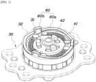
- FIG. 1 is a view illustrating a configuration in which an elastic member 60 is provided in the pumping device according to the present invention
- FIG. 2 is a view for explaining a coupling relationship of the elastic member 60 according to the present invention.
- the pumping device includes: the lever bracket 20 coupled to the lever; the housing 30 having the clutch device 40 provided therein and coupled to a position facing the lever bracket 20 by the clutch device 40; and the elastic member 60 elastically supported on the lever bracket 20 while providing an elastic restoring force in a direction in which an eccentric movement of the clutch device 40 being bent with respect to a rotation axis is canceled.
- the lever bracket 20 rotates when the pumping lever 10 performs a pumping operation. Therefore, even in case that a force is applied to the pumping lever 10 in a transverse direction, the lever bracket 20 freely moves leftward and rightward, such that rotation axes of the lever bracket 20, the clutch device 40, and the brake device 50 are bent and eccentrically arranged.
- the elastic member 60 is used to provide the elastic restoring force to the clutch device 40 in a direction opposite to the direction in which the clutch device 40 is bent and eccentrically arranged, which prevents the rotation axis of the clutch device 40 from being eccentrically arranged. Therefore, the rotation axes of the clutch device 40, the brake device 50, and the pinion 51 are coaxially disposed, which prevents the clutch device 40, the brake device 50, and the pinion 51 from being eccentrically arranged.
- the elastic member 60 supports the lever bracket 20 that freely moves leftward and rightward, such that the lever bracket 20 performs the pumping operation while directly generating friction with the elastic member 60.
- a through-hole 31 may be formed in one surface of the housing 30 that faces the lever bracket 20.
- the elastic member 60 may be provided between an inner surface of the housing 30 and the clutch device 40 and supported on the lever bracket 20 while penetrating the through-hole 31.
- a cylindrical drum part 32 may be provided at a center of the housing 30, and three through-holes 31 may be formed along a periphery of the drum part 32 and disposed at equal angles.
- the elastic member 60 may be provided in the drum part 32, and the elastic member 60 is partially directed toward the lever bracket 20 through the through-holes 31. Therefore, the elastic member 60 is supported on the lever bracket 20 as the elastic member 60 partially passes through the through-holes 31.
- the through-hole 31 is provided in the form of a quadrangular hole.
- a length of the through-hole 31 in a horizontal width direction of the through-hole 31 may correspond to or be longer than a length of the elastic member 60 in a width direction of the elastic member 60 that penetrates the through-hole 31.
- FIG. 3 is a view illustrating the lever bracket 20 and the elastic member 60 according to the present invention
- FIG. 4 is a perspective view illustrating the elastic member 60 according to the present invention.
- the elastic member 60 will be more specifically described with reference to the drawings.
- the elastic member 60 includes: a clutch support portion 60a having a wave shape in a circumferential direction thereof and provided between the inner surface of the housing 30 and the clutch device 40; and bracket support portions 60b protruding from the clutch support portion 60a toward the lever bracket 20 and configured to penetrate the through-holes 31.
- the clutch support portion 60a is provided in the form of a wavy washer having a ring structure having a wave shape.
- the clutch support portion 60a is provided between the inner surface of the drum part 32 and the clutch device 40.
- bracket support portions 60b are disposed along the clutch support portion 60a and formed at positions corresponding to the through-holes 31.
- the bracket support portion 60b penetrates the through-hole 31 to the outside.
- the clutch support portion 60a provides an elastic restoring force in a direction opposite to the direction in which the components, such as the clutch device 40 and the brake device 50 in the housing 30, are bent and eccentrically arranged. Further, the bracket support portions 60b support the lever bracket 20, such that the lever bracket 20 performs the pumping operation while directly generating friction with the elastic member 60.
- the clutch support portion 60a has a structure in which one surface thereof is supported on an inner surface of the cylindrical drum part 32 provided at the center of the housing 30, and the other surface thereof is supported on a rim surface of a clutch drum 42 provided to surround the clutch device 40.
- the rim surface faces the inner surface of the drum part 32.
- bracket support portion 60b has a structure in which one end thereof is fixed to one surface of the clutch support portion 60a, and the other end thereof is supported on the lever bracket 20 facing the housing 30.
- the bracket support portion 60b protrudes in a 'U' shape, and a protruding portion provided at a middle portion of the bracket support portion 60b is in surface contact with the lever bracket 20.
- the clutch support portion 60a is supported between the drum part 32 and the clutch drum 42 and inhibits an eccentric movement of the clutch drum 42, thereby preventing the internal components from being eccentrically arranged with respect to the rotation axis of the clutch device 40.
- bracket support portion 60b has leg portions 61 formed at two opposite ends thereof, and the leg portions 61 are integrated with the clutch support portion 60a.
- a connection portion 62 is formed between the leg portions 61, such that the connection portion 62 is in surface contact with a surface of the lever bracket 20 that faces the housing 30.
- one surface of the clutch support portion 60a may be in contact with the inner surface of the drum part 32 while being disposed on the same plane as the inner surface of the drum part 32.
- the other surface of the clutch support portion 60a may be in contact with the rim surface of the clutch drum 42 while being disposed on the same plane as the rim surface of the clutch drum 42.
- the two opposite surfaces of the clutch support portion 60a are in uniform contact with the drum part 32 and the clutch drum 42, which increases a support area. Therefore, the components in the housing 30 are more stably supported.
- a convex portion of one surface of the clutch support portion 60a may be in line contact with the inner surface of the drum part 32, and a convex portion of the other surface of the clutch support portion 60a may be in line contact with the rim surface of the clutch drum 42.
- the clutch support portion 60a is formed in a wave shape, the convex portion of one surface of the clutch support portion 60a is supported while being in line contact with the inner surface of the drum part 32, and the convex portion of the other surface of the clutch support portion 60a is supported while being in line contact with the rim of the clutch drum 42.
- the eccentric portion of the lever bracket 20 is supported by the bracket support portion 60b existing at the corresponding eccentric position, such that the lever bracket 20 is supported by the bracket support portion 60b, thereby inhibiting an excessive eccentric rotation of the lever bracket 20.
- the clutch drum 42 is also bent toward one side with respect to the rotation axis because of the free leftward and rightward movements of the pumping lever 10. In this case, the clutch drum 42 is bent toward the drum part 32 and pushes a part of the clutch support portion 60a positioned at the corresponding portion.
- the pushed portion is elastically restored by the elastic restoring force of the clutch support portion 60a, and the rotation axis of the clutch drum 42 is also restored to a state in which the rotation axis of the clutch drum 42 is not bent. Therefore, the rotation axes of the clutch device 40, the brake device 50, and the pinion 51 are coaxially disposed.
- the elastic member 60 is used to provide the elastic restoring force to the clutch device 40 in a direction opposite to the direction in which the clutch device 40 is bent and eccentrically arranged, which prevents the rotation axis of the clutch device 40 from being eccentrically arranged. Therefore, the rotation axes of the clutch device 40, the brake device 50, and the pinion 51 are coaxially disposed, which prevents the clutch device 40, the brake device 50, and the pinion 51 from being eccentrically arranged.
- the elastic member 60 supports the lever bracket 20 that freely moves leftward and rightward, such that the lever bracket 20 performs the pumping operation while directly generating friction with the elastic member 60.
- the elastic member 60 reduces operational noise and abnormal noise caused by friction between the rotary component and the stationary component when the pumping device operates, which makes it possible to improve quality and operating performance of the product and more stably perform the pumping operation.
Landscapes
- Engineering & Computer Science (AREA)
- Mechanical Engineering (AREA)
- Aviation & Aerospace Engineering (AREA)
- Transportation (AREA)
- General Engineering & Computer Science (AREA)
- Braking Arrangements (AREA)
- Hydraulic Clutches, Magnetic Clutches, Fluid Clutches, And Fluid Joints (AREA)
Abstract
Description
- The present invention relates to an eccentricity prevention device for a pumping device, which reduces an eccentric movement of an internal component due to an external force while reducing a free movement of a pumping lever.
- A pumping device refers to a device installed in a seat to allow a person seated in the seat to manually adjust a height of a seat cushion to a height suitable for a body type of the person.
- When the person seated in the seat manipulates a pumping lever, which is installed on a lateral surface of the seat cushion, clockwise or counterclockwise, an operating force of the pumping lever is transmitted to a link mechanism through the seat pumping device, and the seat cushion is moved upward or downward depending on a direction in which the pumping lever is manipulated, such that the height of the seat cushion is adjusted.
- A configuration of the pumping device will be briefly described. The pumping device includes a lever bracket integrally coupled to the pumping lever and configured to rotate, a housing having a drum shape and installed in the seat cushion, a clutch device accommodated in the housing and configured to rotate by receiving a rotational force, which is provided from the pumping lever, from the lever bracket, a brake device configured to block reversely inputted torque and maintain an adjusted height of the seat cushion; and a housing cover coupled to one side of the housing and configured to cover the housing.
- In the case of the pumping device, the pumping lever and the lever bracket are integrally coupled. Therefore, when a force is applied to the pumping lever in a transverse direction, the lever bracket is also rotated, which makes it difficult to maintain a gap formed between the lever bracket and the housing to a predetermined level.
- That is, the large gap causes a problem in that the amount of clearance of the pumping lever increases. Further, the small gap causes a problem in that friction occurs between components, an operating force increases or operational noise and abnormal noise occur, which causes a problem with quality.
- Moreover, rotation axes of the clutch device and the brake device, which rotate together with the lever bracket, are eccentrically arranged, which causes a problem in that the components provided in the housing are caught by an inner wall surface of the housing, and a clearance occurs between the internal components.
- As the related art, there is
KR 10-1947534 B - The foregoing explained as the background is intended merely to aid in the understanding of the background of the present invention, and is not intended to mean that the present invention falls within the purview of the related art that is already known to those skilled in the art.
- The present invention has been made in an effort to solve the above-mentioned problem, and an object of the present invention is to provide an eccentricity prevention device for a pumping device, which reduces an eccentric movement of an internal component due to an external force while reducing a free movement of a pumping lever.
- To achieve the above-mentioned object, the present invention provides an eccentricity prevention device for a pumping device, the eccentricity prevention device including: a lever bracket coupled to a pumping lever; a housing having a clutch device provided therein and coupled to a position facing the lever bracket by the clutch device; and an elastic member elastically supported on the lever bracket while providing an elastic restoring force in a direction in which an eccentric movement of the clutch device being bent with respect to a rotation axis is canceled.
- A through-hole may be formed in one surface of the housing that faces the lever bracket, and the elastic member may be provided between an inner surface of the housing and the clutch device and supported on the lever bracket while penetrating the through-hole.
- The elastic member may include: a clutch support portion having a wave shape in a circumferential direction and provided between the inner surface of the housing and the clutch device; and a bracket support portion protruding toward the lever bracket from the clutch support portion and configured to penetrate the through-hole.
- One surface of the clutch support portion may be supported on an inner surface of a cylindrical drum part provided at a center of the housing, the other surface of the clutch support portion may be supported on a rim surface of a clutch drum provided to surround the clutch device, the rim surface of the clutch drum may face the inner surface of the drum part, one end of the bracket support portion may be fixed to one surface of the clutch support portion, and the other end of the bracket support portion may be supported on the lever bracket facing the housing.
- One surface of the clutch support portion may be in contact with the inner surface of the drum part while being disposed on the same plane as the inner surface of the drum part, and the other surface of the clutch support portion may be in contact with the rim surface of the clutch drum while being disposed on the same plane as the rim surface of the clutch drum.
- A convex portion of one surface of the clutch support portion may be in line contact with the inner surface of the drum part, and a convex portion of the other surface of the clutch support portion may be in line contact with the rim surface of the clutch drum.
- The bracket support portion may protrude in a 'U' shape, and a protruding portion provided at a middle portion of the bracket support portion may be in surface contact with the lever bracket.
- According to the technical solution of the present invention, the elastic member reduces operational noise and abnormal noise caused by friction between the rotary component and the stationary component when the pumping device operates, which makes it possible to improve quality and operating performance of the product and more stably perform the pumping operation.
-
-
FIG. 1 is a view illustrating a configuration in which an elastic member is provided in a pumping device according to the present invention. -
FIG. 2 is a view for explaining a coupling relationship of the elastic member according to the present invention. -
FIG. 3 is a view illustrating a lever bracket and the elastic member according to the present invention. -
FIG. 4 is a perspective view illustrating the elastic member according to the present invention. - Hereinafter, exemplary embodiments of the present disclosure will be described in detail with reference to the accompanying drawings.
- A pumping device of the present invention includes a
housing 30 fixed to a seat cushion (not illustrated), and aclutch device 40 provided in thehousing 30. - Further, a
lever bracket 20 is fixed to aclutch cam 41 that constitutes theclutch device 40, and apumping lever 10 is coupled to thelever bracket 20, such that theclutch device 40 is rotated by a rotation of thepumping lever 10. - Further, a
brake device 50 is provided in thehousing 30, and apinion 51 is coupled to thebrake device 50, such that a rotational force transmitted to theclutch device 40 is outputted through thepinion 51 and moves a seat upward or downward. - However, because the description of specific configurations of the
clutch device 40 and thebrake device 50 and the description of a pumping operation using these components are publicly-known technologies, the specific descriptions thereof will be omitted. - Meanwhile,
FIG. 1 is a view illustrating a configuration in which anelastic member 60 is provided in the pumping device according to the present invention, andFIG. 2 is a view for explaining a coupling relationship of theelastic member 60 according to the present invention. - The distinctive technical configuration of the present invention will be specifically described with reference to the drawings. The pumping device includes: the
lever bracket 20 coupled to the lever; thehousing 30 having theclutch device 40 provided therein and coupled to a position facing thelever bracket 20 by theclutch device 40; and theelastic member 60 elastically supported on thelever bracket 20 while providing an elastic restoring force in a direction in which an eccentric movement of theclutch device 40 being bent with respect to a rotation axis is canceled. - That is, because the
pumping lever 10 and thelever bracket 20 are fastened to each other by bolting or the like, thelever bracket 20 rotates when thepumping lever 10 performs a pumping operation. Therefore, even in case that a force is applied to thepumping lever 10 in a transverse direction, thelever bracket 20 freely moves leftward and rightward, such that rotation axes of thelever bracket 20, theclutch device 40, and thebrake device 50 are bent and eccentrically arranged. - Therefore, in the present invention, the
elastic member 60 is used to provide the elastic restoring force to theclutch device 40 in a direction opposite to the direction in which theclutch device 40 is bent and eccentrically arranged, which prevents the rotation axis of theclutch device 40 from being eccentrically arranged. Therefore, the rotation axes of theclutch device 40, thebrake device 50, and thepinion 51 are coaxially disposed, which prevents theclutch device 40, thebrake device 50, and thepinion 51 from being eccentrically arranged. - In particular, the
elastic member 60 supports thelever bracket 20 that freely moves leftward and rightward, such that thelever bracket 20 performs the pumping operation while directly generating friction with theelastic member 60. - Therefore, it is possible to reduce operational noise and abnormal noise caused by friction between the rotary component and the stationary component when the pumping device operates, which makes it possible to improve quality and operating performance of the product and more stably perform the pumping operation.
- Further, as illustrated in
FIGS. 1 and2 , a through-hole 31 may be formed in one surface of thehousing 30 that faces thelever bracket 20. Theelastic member 60 may be provided between an inner surface of thehousing 30 and theclutch device 40 and supported on thelever bracket 20 while penetrating the through-hole 31. - For example, a
cylindrical drum part 32 may be provided at a center of thehousing 30, and three through-holes 31 may be formed along a periphery of thedrum part 32 and disposed at equal angles. - Further, the
elastic member 60 may be provided in thedrum part 32, and theelastic member 60 is partially directed toward thelever bracket 20 through the through-holes 31. Therefore, theelastic member 60 is supported on thelever bracket 20 as theelastic member 60 partially passes through the through-holes 31. - For reference, the through-
hole 31 is provided in the form of a quadrangular hole. A length of the through-hole 31 in a horizontal width direction of the through-hole 31 may correspond to or be longer than a length of theelastic member 60 in a width direction of theelastic member 60 that penetrates the through-hole 31. -
FIG. 3 is a view illustrating thelever bracket 20 and theelastic member 60 according to the present invention, andFIG. 4 is a perspective view illustrating theelastic member 60 according to the present invention. - The
elastic member 60 will be more specifically described with reference to the drawings. Theelastic member 60 includes: aclutch support portion 60a having a wave shape in a circumferential direction thereof and provided between the inner surface of thehousing 30 and theclutch device 40; andbracket support portions 60b protruding from theclutch support portion 60a toward thelever bracket 20 and configured to penetrate the through-holes 31. - For example, the
clutch support portion 60a is provided in the form of a wavy washer having a ring structure having a wave shape. Theclutch support portion 60a is provided between the inner surface of thedrum part 32 and theclutch device 40. - Further, the
bracket support portions 60b are disposed along theclutch support portion 60a and formed at positions corresponding to the through-holes 31. Thebracket support portion 60b penetrates the through-hole 31 to the outside. - Therefore, the
clutch support portion 60a provides an elastic restoring force in a direction opposite to the direction in which the components, such as theclutch device 40 and thebrake device 50 in thehousing 30, are bent and eccentrically arranged. Further, thebracket support portions 60b support thelever bracket 20, such that thelever bracket 20 performs the pumping operation while directly generating friction with theelastic member 60. - Further, referring to
FIG. 2 , theclutch support portion 60a has a structure in which one surface thereof is supported on an inner surface of thecylindrical drum part 32 provided at the center of thehousing 30, and the other surface thereof is supported on a rim surface of aclutch drum 42 provided to surround theclutch device 40. The rim surface faces the inner surface of thedrum part 32. - Further, the
bracket support portion 60b has a structure in which one end thereof is fixed to one surface of theclutch support portion 60a, and the other end thereof is supported on thelever bracket 20 facing thehousing 30. - The
bracket support portion 60b protrudes in a 'U' shape, and a protruding portion provided at a middle portion of thebracket support portion 60b is in surface contact with thelever bracket 20. - That is, the
clutch support portion 60a is supported between thedrum part 32 and theclutch drum 42 and inhibits an eccentric movement of theclutch drum 42, thereby preventing the internal components from being eccentrically arranged with respect to the rotation axis of theclutch device 40. - In addition, the
bracket support portion 60b hasleg portions 61 formed at two opposite ends thereof, and theleg portions 61 are integrated with theclutch support portion 60a. Aconnection portion 62 is formed between theleg portions 61, such that theconnection portion 62 is in surface contact with a surface of thelever bracket 20 that faces thehousing 30. - Further, as illustrated in
FIG. 3 , one surface of theclutch support portion 60a may be in contact with the inner surface of thedrum part 32 while being disposed on the same plane as the inner surface of thedrum part 32. The other surface of theclutch support portion 60a may be in contact with the rim surface of theclutch drum 42 while being disposed on the same plane as the rim surface of theclutch drum 42. - Therefore, the two opposite surfaces of the
clutch support portion 60a are in uniform contact with thedrum part 32 and theclutch drum 42, which increases a support area. Therefore, the components in thehousing 30 are more stably supported. - Therefore, a convex portion of one surface of the
clutch support portion 60a may be in line contact with the inner surface of thedrum part 32, and a convex portion of the other surface of theclutch support portion 60a may be in line contact with the rim surface of theclutch drum 42. - That is, because the
clutch support portion 60a is formed in a wave shape, the convex portion of one surface of theclutch support portion 60a is supported while being in line contact with the inner surface of thedrum part 32, and the convex portion of the other surface of theclutch support portion 60a is supported while being in line contact with the rim of theclutch drum 42. - Therefore, it is possible to prevent stress from being concentrated on particular portions of the
drum part 32 and theclutch drum 42, thereby improving component durability. - With this configuration, in case that the
lever bracket 20 is bent toward one side because of free leftward and rightward movements of the pumpinglever 10, one side of thelever bracket 20 is eccentrically rotated toward thehousing 30. - Then, the eccentric portion of the
lever bracket 20 is supported by thebracket support portion 60b existing at the corresponding eccentric position, such that thelever bracket 20 is supported by thebracket support portion 60b, thereby inhibiting an excessive eccentric rotation of thelever bracket 20. - Further, the
clutch drum 42 is also bent toward one side with respect to the rotation axis because of the free leftward and rightward movements of the pumpinglever 10. In this case, theclutch drum 42 is bent toward thedrum part 32 and pushes a part of theclutch support portion 60a positioned at the corresponding portion. - Then, the pushed portion is elastically restored by the elastic restoring force of the
clutch support portion 60a, and the rotation axis of theclutch drum 42 is also restored to a state in which the rotation axis of theclutch drum 42 is not bent. Therefore, the rotation axes of theclutch device 40, thebrake device 50, and thepinion 51 are coaxially disposed. - As described above, in the present invention, the
elastic member 60 is used to provide the elastic restoring force to theclutch device 40 in a direction opposite to the direction in which theclutch device 40 is bent and eccentrically arranged, which prevents the rotation axis of theclutch device 40 from being eccentrically arranged. Therefore, the rotation axes of theclutch device 40, thebrake device 50, and thepinion 51 are coaxially disposed, which prevents theclutch device 40, thebrake device 50, and thepinion 51 from being eccentrically arranged. - In particular, the
elastic member 60 supports thelever bracket 20 that freely moves leftward and rightward, such that thelever bracket 20 performs the pumping operation while directly generating friction with theelastic member 60. - Therefore, the
elastic member 60 reduces operational noise and abnormal noise caused by friction between the rotary component and the stationary component when the pumping device operates, which makes it possible to improve quality and operating performance of the product and more stably perform the pumping operation. - While the present invention has been described with reference to the specific examples, it is apparent to those skilled in the art that various modifications and alterations may be made within the technical spirit of the present invention, and these modifications and alterations belong to the appended claims.
-
- 10: Pumping lever
- 20: Lever bracket
- 30: Housing
- 31: Through-hole
- 32: Drum part
- 40: Clutch device
- 41: Clutch cam
- 42: Clutch drum
- 50: Brake device
- 51: Pinion
- 60: Elastic member
- 60a: Clutch support portion
- 60b: Bracket support portion
- 61: Leg portion
- 62: Connection portion
Claims (7)
- An eccentricity prevention device for a pumping device, the eccentricity prevention device comprising:a lever bracket coupled to a pumping lever;a housing having a clutch device provided therein and coupled to a position facing the lever bracket by the clutch device; andan elastic member elastically supported on the lever bracket while providing an elastic restoring force in a direction in which an eccentric movement of the clutch device being bent with respect to a rotation axis is canceled.
- The eccentricity prevention device of claim 1, wherein a through-hole is formed in one surface of the housing that faces the lever bracket, and the elastic member is provided between an inner surface of the housing and the clutch device and supported on the lever bracket while penetrating the through-hole.
- The eccentricity prevention device of claim 2, wherein the elastic member comprises:a clutch support portion having a wave shape in a circumferential direction and provided between the inner surface of the housing and the clutch device; anda bracket support portion protruding toward the lever bracket from the clutch support portion and configured to penetrate the through-hole.
- The eccentricity prevention device of claim 3, wherein one surface of the clutch support portion is supported on an inner surface of a cylindrical drum part provided at a center of the housing, the other surface of the clutch support portion is supported on a rim surface of a clutch drum provided to surround the clutch device, and the rim surface of the clutch drum faces the inner surface of the drum part, and
wherein one end of the bracket support portion is fixed to one surface of the clutch support portion, and the other end of the bracket support portion is supported on the lever bracket facing the housing. - The eccentricity prevention device of claim 3, wherein one surface of the clutch support portion is in contact with the inner surface of the drum part while being disposed on the same plane as the inner surface of the drum part, and the other surface of the clutch support portion is in contact with the rim surface of the clutch drum while being disposed on the same plane as the rim surface of the clutch drum.
- The eccentricity prevention device of claim 5, wherein a convex portion of one surface of the clutch support portion is in line contact with the inner surface of the drum part, and a convex portion of the other surface of the clutch support portion is in line contact with the rim surface of the clutch drum.
- The eccentricity prevention device of claim 3, wherein the bracket support portion protrudes in a 'U' shape, and a protruding portion provided at a middle portion of the bracket support portion is in surface contact with the lever bracket.
Applications Claiming Priority (2)
| Application Number | Priority Date | Filing Date | Title |
|---|---|---|---|
| KR1020200130125A KR102848766B1 (en) | 2020-10-08 | 2020-10-08 | Eccentrictiy prevention device for pumping device |
| PCT/KR2021/007619 WO2022075552A1 (en) | 2020-10-08 | 2021-06-17 | Eccentricity prevention device for pumping device |
Publications (2)
| Publication Number | Publication Date |
|---|---|
| EP4227151A1 true EP4227151A1 (en) | 2023-08-16 |
| EP4227151A4 EP4227151A4 (en) | 2024-10-23 |
Family
ID=81126145
Family Applications (1)
| Application Number | Title | Priority Date | Filing Date |
|---|---|---|---|
| EP21877807.4A Pending EP4227151A4 (en) | 2020-10-08 | 2021-06-17 | DEVICE FOR PREVENTING ECCENTRICITY FOR A PUMPING DEVICE |
Country Status (5)
| Country | Link |
|---|---|
| US (1) | US12092192B2 (en) |
| EP (1) | EP4227151A4 (en) |
| KR (1) | KR102848766B1 (en) |
| CN (1) | CN116457238B (en) |
| WO (1) | WO2022075552A1 (en) |
Family Cites Families (15)
| Publication number | Priority date | Publication date | Assignee | Title |
|---|---|---|---|---|
| JP2004338426A (en) | 2003-05-13 | 2004-12-02 | Fuji Kiko Co Ltd | Height adjustment device for vehicle seat |
| EP2273144B1 (en) * | 2003-09-22 | 2012-11-28 | Litens Automotive Partnership | Crankshaft decoupler |
| KR100840486B1 (en) | 2006-03-24 | 2008-06-20 | 주식회사 오스템 | Pumping device and height adjustment mechanism of vehicle seat having same |
| JP4987336B2 (en) * | 2006-03-31 | 2012-07-25 | Ntn株式会社 | Seat seat |
| KR100956729B1 (en) * | 2009-12-11 | 2010-05-06 | 대원정밀공업(주) | Pumping device for vehicle seat cushion |
| JP2012067792A (en) | 2010-09-21 | 2012-04-05 | Ntn Corp | Clutch unit |
| KR101361912B1 (en) * | 2013-02-15 | 2014-02-13 | 계양전기 주식회사 | Eccentricity power transfer apparatus and seat height control apparatus |
| KR101791993B1 (en) * | 2016-03-03 | 2017-11-01 | 현대다이모스(주) | Seat pumping device of vehicle |
| KR101943962B1 (en) * | 2016-10-25 | 2019-01-31 | 주식회사 다스 | Height adjustment apparatus for seat of vehicle |
| KR101903882B1 (en) * | 2017-02-28 | 2018-11-13 | 주식회사평화발레오 | Double Clutch Assembly |
| KR101987977B1 (en) * | 2017-12-26 | 2019-06-11 | 현대트랜시스(주) | Fluttering prevention apparatus for lever of pumping device |
| KR101947534B1 (en) | 2017-12-26 | 2019-02-13 | 현대트랜시스(주) | Pumping device for seat of vehicle |
| KR102011087B1 (en) * | 2017-12-26 | 2019-08-14 | 현대트랜시스(주) | Seat pumping device for vehicle |
| CN108045276A (en) * | 2018-01-04 | 2018-05-18 | 无锡全盛安仁机械有限公司 | A kind of manual half basin lifting apparatus of automotive seat direct-drive type |
| KR102263734B1 (en) * | 2019-06-05 | 2021-06-11 | 현대트랜시스 주식회사 | Eccentrictiy prevention device for pumping device |
-
2020
- 2020-10-08 KR KR1020200130125A patent/KR102848766B1/en active Active
-
2021
- 2021-06-17 US US18/246,875 patent/US12092192B2/en active Active
- 2021-06-17 WO PCT/KR2021/007619 patent/WO2022075552A1/en not_active Ceased
- 2021-06-17 CN CN202180068811.3A patent/CN116457238B/en active Active
- 2021-06-17 EP EP21877807.4A patent/EP4227151A4/en active Pending
Also Published As
| Publication number | Publication date |
|---|---|
| US20230366455A1 (en) | 2023-11-16 |
| CN116457238B (en) | 2025-10-24 |
| KR20220046890A (en) | 2022-04-15 |
| US12092192B2 (en) | 2024-09-17 |
| EP4227151A4 (en) | 2024-10-23 |
| WO2022075552A1 (en) | 2022-04-14 |
| CN116457238A (en) | 2023-07-18 |
| KR102848766B1 (en) | 2025-08-20 |
Similar Documents
| Publication | Publication Date | Title |
|---|---|---|
| JP4293902B2 (en) | Belt tensioner with mounting pin | |
| KR100690262B1 (en) | Axial lock device | |
| JP2007144121A (en) | Inclination adjustment fitting for back rest of vehicle seat | |
| KR20040058060A (en) | hinge | |
| KR20170103277A (en) | Seat pumping device of vehicle | |
| US20110239405A1 (en) | Hinge mechanism | |
| CN110556967B (en) | Linear drive device | |
| US12209450B2 (en) | One-way damping hinge | |
| KR101709599B1 (en) | Device recliner for vehicle | |
| EP4227151A1 (en) | Eccentricity prevention device for pumping device | |
| JP2001254842A (en) | Mechanical seal | |
| JP2007526052A (en) | Vehicle seat fitting | |
| KR100263517B1 (en) | Bearing cup and retainer strap for universal joint | |
| KR100457547B1 (en) | Pipe spring having flange and hinge device using that | |
| KR101732373B1 (en) | Pumping device of seat for vehicle | |
| JP7579575B2 (en) | Composite Device | |
| KR200304811Y1 (en) | Pipe spring having flange and hinge device using that | |
| US6659257B2 (en) | Torque transmission device | |
| JP3424737B2 (en) | Auto tensioner | |
| US12034354B2 (en) | Spring retention system for dc motor | |
| EP4010596B1 (en) | Rotor and pump comprising such rotor | |
| JP2001003927A (en) | Shaft locking device | |
| JP2023065113A (en) | reclining device | |
| KR100754506B1 (en) | Swing yoke prevention structure | |
| JP2024171461A (en) | Scissors Gear |
Legal Events
| Date | Code | Title | Description |
|---|---|---|---|
| STAA | Information on the status of an ep patent application or granted ep patent |
Free format text: STATUS: THE INTERNATIONAL PUBLICATION HAS BEEN MADE |
|
| PUAI | Public reference made under article 153(3) epc to a published international application that has entered the european phase |
Free format text: ORIGINAL CODE: 0009012 |
|
| STAA | Information on the status of an ep patent application or granted ep patent |
Free format text: STATUS: REQUEST FOR EXAMINATION WAS MADE |
|
| 17P | Request for examination filed |
Effective date: 20230320 |
|
| AK | Designated contracting states |
Kind code of ref document: A1 Designated state(s): AL AT BE BG CH CY CZ DE DK EE ES FI FR GB GR HR HU IE IS IT LI LT LU LV MC MK MT NL NO PL PT RO RS SE SI SK SM TR |
|
| DAV | Request for validation of the european patent (deleted) | ||
| DAX | Request for extension of the european patent (deleted) | ||
| A4 | Supplementary search report drawn up and despatched |
Effective date: 20240925 |
|
| RIC1 | Information provided on ipc code assigned before grant |
Ipc: B60N 2/16 20060101AFI20240919BHEP |
|
| STAA | Information on the status of an ep patent application or granted ep patent |
Free format text: STATUS: EXAMINATION IS IN PROGRESS |
|
| 17Q | First examination report despatched |
Effective date: 20250918 |