EP4227135A1 - Powertrain, method for controlling cooling of powertrain, and vehicle - Google Patents
Powertrain, method for controlling cooling of powertrain, and vehicle Download PDFInfo
- Publication number
- EP4227135A1 EP4227135A1 EP23155509.5A EP23155509A EP4227135A1 EP 4227135 A1 EP4227135 A1 EP 4227135A1 EP 23155509 A EP23155509 A EP 23155509A EP 4227135 A1 EP4227135 A1 EP 4227135A1
- Authority
- EP
- European Patent Office
- Prior art keywords
- pump
- powertrain
- rotational speed
- coolant
- rotor
- Prior art date
- Legal status (The legal status is an assumption and is not a legal conclusion. Google has not performed a legal analysis and makes no representation as to the accuracy of the status listed.)
- Granted
Links
Images

Classifications
-
- B—PERFORMING OPERATIONS; TRANSPORTING
- B60—VEHICLES IN GENERAL
- B60K—ARRANGEMENT OR MOUNTING OF PROPULSION UNITS OR OF TRANSMISSIONS IN VEHICLES; ARRANGEMENT OR MOUNTING OF PLURAL DIVERSE PRIME-MOVERS IN VEHICLES; AUXILIARY DRIVES FOR VEHICLES; INSTRUMENTATION OR DASHBOARDS FOR VEHICLES; ARRANGEMENTS IN CONNECTION WITH COOLING, AIR INTAKE, GAS EXHAUST OR FUEL SUPPLY OF PROPULSION UNITS IN VEHICLES
- B60K11/00—Arrangement in connection with cooling of propulsion units
- B60K11/02—Arrangement in connection with cooling of propulsion units with liquid cooling
-
- B—PERFORMING OPERATIONS; TRANSPORTING
- B60—VEHICLES IN GENERAL
- B60K—ARRANGEMENT OR MOUNTING OF PROPULSION UNITS OR OF TRANSMISSIONS IN VEHICLES; ARRANGEMENT OR MOUNTING OF PLURAL DIVERSE PRIME-MOVERS IN VEHICLES; AUXILIARY DRIVES FOR VEHICLES; INSTRUMENTATION OR DASHBOARDS FOR VEHICLES; ARRANGEMENTS IN CONNECTION WITH COOLING, AIR INTAKE, GAS EXHAUST OR FUEL SUPPLY OF PROPULSION UNITS IN VEHICLES
- B60K1/00—Arrangement or mounting of electrical propulsion units
-
- B—PERFORMING OPERATIONS; TRANSPORTING
- B60—VEHICLES IN GENERAL
- B60K—ARRANGEMENT OR MOUNTING OF PROPULSION UNITS OR OF TRANSMISSIONS IN VEHICLES; ARRANGEMENT OR MOUNTING OF PLURAL DIVERSE PRIME-MOVERS IN VEHICLES; AUXILIARY DRIVES FOR VEHICLES; INSTRUMENTATION OR DASHBOARDS FOR VEHICLES; ARRANGEMENTS IN CONNECTION WITH COOLING, AIR INTAKE, GAS EXHAUST OR FUEL SUPPLY OF PROPULSION UNITS IN VEHICLES
- B60K7/00—Disposition of motor in, or adjacent to, traction wheel
- B60K7/0007—Disposition of motor in, or adjacent to, traction wheel the motor being electric
-
- F—MECHANICAL ENGINEERING; LIGHTING; HEATING; WEAPONS; BLASTING
- F16—ENGINEERING ELEMENTS AND UNITS; GENERAL MEASURES FOR PRODUCING AND MAINTAINING EFFECTIVE FUNCTIONING OF MACHINES OR INSTALLATIONS; THERMAL INSULATION IN GENERAL
- F16H—GEARING
- F16H57/00—General details of gearing
- F16H57/04—Features relating to lubrication or cooling or heating
- F16H57/0412—Cooling or heating; Control of temperature
- F16H57/0413—Controlled cooling or heating of lubricant; Temperature control therefor
-
- F—MECHANICAL ENGINEERING; LIGHTING; HEATING; WEAPONS; BLASTING
- F16—ENGINEERING ELEMENTS AND UNITS; GENERAL MEASURES FOR PRODUCING AND MAINTAINING EFFECTIVE FUNCTIONING OF MACHINES OR INSTALLATIONS; THERMAL INSULATION IN GENERAL
- F16H—GEARING
- F16H57/00—General details of gearing
- F16H57/04—Features relating to lubrication or cooling or heating
- F16H57/0412—Cooling or heating; Control of temperature
- F16H57/0415—Air cooling or ventilation; Heat exchangers; Thermal insulations
- F16H57/0417—Heat exchangers adapted or integrated in the gearing
-
- H—ELECTRICITY
- H02—GENERATION; CONVERSION OR DISTRIBUTION OF ELECTRIC POWER
- H02K—DYNAMO-ELECTRIC MACHINES
- H02K7/00—Arrangements for handling mechanical energy structurally associated with dynamo-electric machines, e.g. structural association with mechanical driving motors or auxiliary dynamo-electric machines
- H02K7/10—Structural association with clutches, brakes, gears, pulleys or mechanical starters
- H02K7/116—Structural association with clutches, brakes, gears, pulleys or mechanical starters with gears
-
- H—ELECTRICITY
- H02—GENERATION; CONVERSION OR DISTRIBUTION OF ELECTRIC POWER
- H02K—DYNAMO-ELECTRIC MACHINES
- H02K9/00—Arrangements for cooling or ventilating
- H02K9/19—Arrangements for cooling or ventilating for machines with closed casing and closed-circuit cooling using a liquid cooling medium, e.g. oil
-
- H—ELECTRICITY
- H02—GENERATION; CONVERSION OR DISTRIBUTION OF ELECTRIC POWER
- H02K—DYNAMO-ELECTRIC MACHINES
- H02K9/00—Arrangements for cooling or ventilating
- H02K9/26—Structural association of machines with devices for cleaning or drying cooling medium, e.g. with filters
-
- B—PERFORMING OPERATIONS; TRANSPORTING
- B60—VEHICLES IN GENERAL
- B60K—ARRANGEMENT OR MOUNTING OF PROPULSION UNITS OR OF TRANSMISSIONS IN VEHICLES; ARRANGEMENT OR MOUNTING OF PLURAL DIVERSE PRIME-MOVERS IN VEHICLES; AUXILIARY DRIVES FOR VEHICLES; INSTRUMENTATION OR DASHBOARDS FOR VEHICLES; ARRANGEMENTS IN CONNECTION WITH COOLING, AIR INTAKE, GAS EXHAUST OR FUEL SUPPLY OF PROPULSION UNITS IN VEHICLES
- B60K1/00—Arrangement or mounting of electrical propulsion units
- B60K1/02—Arrangement or mounting of electrical propulsion units comprising more than one electric motor
-
- B—PERFORMING OPERATIONS; TRANSPORTING
- B60—VEHICLES IN GENERAL
- B60K—ARRANGEMENT OR MOUNTING OF PROPULSION UNITS OR OF TRANSMISSIONS IN VEHICLES; ARRANGEMENT OR MOUNTING OF PLURAL DIVERSE PRIME-MOVERS IN VEHICLES; AUXILIARY DRIVES FOR VEHICLES; INSTRUMENTATION OR DASHBOARDS FOR VEHICLES; ARRANGEMENTS IN CONNECTION WITH COOLING, AIR INTAKE, GAS EXHAUST OR FUEL SUPPLY OF PROPULSION UNITS IN VEHICLES
- B60K17/00—Arrangement or mounting of transmissions in vehicles
- B60K17/04—Arrangement or mounting of transmissions in vehicles characterised by arrangement, location or kind of gearing
- B60K17/043—Transmission unit disposed in on near the vehicle wheel, or between the differential gear unit and the wheel
-
- B—PERFORMING OPERATIONS; TRANSPORTING
- B60—VEHICLES IN GENERAL
- B60K—ARRANGEMENT OR MOUNTING OF PROPULSION UNITS OR OF TRANSMISSIONS IN VEHICLES; ARRANGEMENT OR MOUNTING OF PLURAL DIVERSE PRIME-MOVERS IN VEHICLES; AUXILIARY DRIVES FOR VEHICLES; INSTRUMENTATION OR DASHBOARDS FOR VEHICLES; ARRANGEMENTS IN CONNECTION WITH COOLING, AIR INTAKE, GAS EXHAUST OR FUEL SUPPLY OF PROPULSION UNITS IN VEHICLES
- B60K1/00—Arrangement or mounting of electrical propulsion units
- B60K2001/003—Arrangement or mounting of electrical propulsion units with means for cooling the electrical propulsion units
- B60K2001/006—Arrangement or mounting of electrical propulsion units with means for cooling the electrical propulsion units the electric motors
-
- B—PERFORMING OPERATIONS; TRANSPORTING
- B60—VEHICLES IN GENERAL
- B60K—ARRANGEMENT OR MOUNTING OF PROPULSION UNITS OR OF TRANSMISSIONS IN VEHICLES; ARRANGEMENT OR MOUNTING OF PLURAL DIVERSE PRIME-MOVERS IN VEHICLES; AUXILIARY DRIVES FOR VEHICLES; INSTRUMENTATION OR DASHBOARDS FOR VEHICLES; ARRANGEMENTS IN CONNECTION WITH COOLING, AIR INTAKE, GAS EXHAUST OR FUEL SUPPLY OF PROPULSION UNITS IN VEHICLES
- B60K7/00—Disposition of motor in, or adjacent to, traction wheel
- B60K2007/0046—Disposition of motor in, or adjacent to, traction wheel the motor moving together with the vehicle body, i.e. moving independently from the wheel axle
-
- B—PERFORMING OPERATIONS; TRANSPORTING
- B60—VEHICLES IN GENERAL
- B60K—ARRANGEMENT OR MOUNTING OF PROPULSION UNITS OR OF TRANSMISSIONS IN VEHICLES; ARRANGEMENT OR MOUNTING OF PLURAL DIVERSE PRIME-MOVERS IN VEHICLES; AUXILIARY DRIVES FOR VEHICLES; INSTRUMENTATION OR DASHBOARDS FOR VEHICLES; ARRANGEMENTS IN CONNECTION WITH COOLING, AIR INTAKE, GAS EXHAUST OR FUEL SUPPLY OF PROPULSION UNITS IN VEHICLES
- B60K7/00—Disposition of motor in, or adjacent to, traction wheel
- B60K2007/0061—Disposition of motor in, or adjacent to, traction wheel the motor axle being parallel to the wheel axle
-
- B—PERFORMING OPERATIONS; TRANSPORTING
- B60—VEHICLES IN GENERAL
- B60Y—INDEXING SCHEME RELATING TO ASPECTS CROSS-CUTTING VEHICLE TECHNOLOGY
- B60Y2306/00—Other features of vehicle sub-units
- B60Y2306/03—Lubrication
-
- B—PERFORMING OPERATIONS; TRANSPORTING
- B60—VEHICLES IN GENERAL
- B60Y—INDEXING SCHEME RELATING TO ASPECTS CROSS-CUTTING VEHICLE TECHNOLOGY
- B60Y2400/00—Special features of vehicle units
- B60Y2400/30—Sensors
- B60Y2400/302—Temperature sensors
-
- B—PERFORMING OPERATIONS; TRANSPORTING
- B60—VEHICLES IN GENERAL
- B60Y—INDEXING SCHEME RELATING TO ASPECTS CROSS-CUTTING VEHICLE TECHNOLOGY
- B60Y2410/00—Constructional features of vehicle sub-units
- B60Y2410/102—Shaft arrangements; Shaft supports, e.g. bearings
Definitions
- This application generally relates to the field of vehicles, and more specifically, this application relates to a powertrain, a method for controlling cooling of a powertrain, and a vehicle.
- a powertrain of a vehicle needs to output a higher rotational speed and a larger torque. This causes more heat to be generated in the powertrain. As a result, efficiency of the powertrain is reduced, and adverse impact is imposed on performance of the powertrain. This imposes a higher requirement for cooling efficiency of the powertrain.
- a dual-drive vehicle model is used as an example.
- a dual-drive powertrain includes dual motors and dual gearboxes. Because a quantity of components is doubled, a requirement for cooling oil is doubled. In addition, arrangement of a cooling oil path is also more complex, making processing and manufacturing difficult.
- Embodiments of this application provide a powertrain, a method for controlling cooling of the powertrain, and a corresponding vehicle, to at least partially resolve the foregoing and/or other potential problems in a conventional technology.
- a powertrain includes: a reservoir, configured to store coolant; a first drive motor, where the first drive motor includes a first stator and a first rotor; a second drive motor, where the second drive motor includes a second stator and a second rotor; a first pump and a second pump, where an inlet of the first pump is connected to the reservoir, and an inlet of the second pump is connected to the reservoir; a heat exchanger, where the heat exchanger is connected to the first pump; a first flow path, where the first flow path is connected to an outlet of the first pump, and the first flow path is used to supply the coolant to the first stator and the second stator through the heat exchanger; and a second flow path, where the second flow path is connected to an outlet of the second pump, and the second flow path is used to supply the coolant to the first rotor and the second rotor.
- the coolant used to cool the rotors and the stators of the powertrain is separately transmitted, and the coolant for cooling the stators passes through the heat exchanger, so that cooling effect can be properly optimized.
- the powertrain further includes: a first gearbox, where the first gearbox is connected to the first rotor; a second gearbox, where the second gearbox is connected to the second rotor; and a third flow path, where the third flow path is connected to the second flow path, and is used to supply the coolant to the first gearbox and the second gearbox.
- the powertrain further includes: a rotor bearing, configured to support the first rotor and the second rotor; and a fourth flow path, where the fourth flow path is connected to at least one of the first flow path and the second flow path, and is used to supply the coolant to the rotor bearing.
- the powertrain further includes a first filter, where the first filter is disposed between the reservoir and the first pump, and is configured to filter the coolant before the coolant is drawn off by the first pump.
- the powertrain further includes a second filter, where the second filter is disposed between the reservoir and the second pump, and is configured to filter the coolant before the coolant is drawn off by the second pump.
- a method for controlling cooling of the powertrain includes: determining a temperature of the powertrain; determining a rotational speed of the first pump and a rotational speed the second pump; and adjusting the rotational speed of the first pump and/or the rotational speed of the second pump based on the temperature of the powertrain.
- the adjusting the rotational speed of the first pump and/or the rotational speed of the second pump based on the temperature of the powertrain includes: increasing the rotational speed of the first pump and/or the rotational speed of the second pump in response to that the temperature of the powertrain is higher than a target temperature.
- the increasing the rotational speed of the first pump and/or the rotational speed of the second pump includes: increasing both the rotational speed of the first pump and the rotational speed of the second pump in response to that the rotational speed of the first pump is consistent with the rotational speed of the second pump.
- the increasing the rotational speed of the first pump and/or the rotational speed of the second pump includes: in response to that the rotational speed of the first pump is inconsistent with the rotational speed of the second pump, increasing a rotational speed of a pump, of the first pump and the second pump, that has a lower rotational speed.
- the rotational speed of the first pump and the rotational speed of the second pump can be properly adjusted and controlled.
- the adjusting the rotational speed of the first pump and/or the rotational speed of the second pump based on the temperature of the powertrain includes: reducing the rotational speed of the first pump in response to that the temperature of the powertrain is lower than a target temperature. With this arrangement, a power of the first pump can be saved.
- the determining a rotational speed of the first pump includes: determining the rotational speed of the first pump based on an amount of heat generated by the powertrain and a temperature of coolant in the heat exchanger. With this arrangement, factors of the powertrain and the heat exchanger are considered, so that the rotational speed of the first pump is more properly adjusted.
- the determining a rotational speed of the second pump includes: determining the rotational speed of the second pump based on a rotational speed and a torque of the powertrain. With this arrangement, an operating condition of the powertrain is considered, so that the rotational speed of the second pump is more properly adjusted.
- a vehicle includes a drive wheel and the powertrain according to the first aspect of this application, where the powertrain is connected to the drive wheel in a transmission manner.
- the term “include” and similar terms thereof should be understood as open-ended inclusion, that is, “including but not limited to”.
- the term “based on” should be understood as “at least partially based on”.
- the term “an embodiment” or “the embodiment” should be understood as “at least one embodiment”.
- the terms “first”, “second”, and the like may indicate different or same objects. Other explicit and implicit definitions may be further included in the following descriptions.
- a pump draws coolant from a reservoir that stores the coolant, to cool a stator and a rotor in a powertrain. After cooling is completed, the coolant is transmitted back to the reservoir. Then a temperature of the coolant decreases through heat exchange of a heat exchanger, and the coolant cools the stator and the rotor again under a pumping function of the pump, thereby implementing circular cooling.
- an order of magnitude of an amount of heat generated by the stator of the powertrain is usually kilowatts, and an order of magnitude of an amount of heat generated by the rotor is usually hectowatts.
- a single pump and a single heat exchanger are designed, and cooling paths for the stator and the rotor are not distinguished. Therefore, cooling effect is quite limited.
- a cooling system includes a complex pipeline structure. This leads to an increased size and a redundant structure of the cooling system, and is also quite inconvenient for maintenance by a person when a failure occurs.
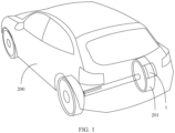
- FIG. 1 is a schematic diagram of a structure of a vehicle 200 according to an embodiment of this application.
- the vehicle 200 includes a drive wheel 201 and a powertrain 1.
- the powertrain 1 may be connected to the drive wheel 201 in a transmission manner, and is configured to provide driving force for the vehicle 200, so that the vehicle 200 can operate normally.
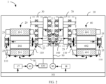
- FIG. 2 shows the powertrain 1 of the vehicle 200 according to an embodiment of this disclosure.
- the powertrain 1 in this embodiment may include a reservoir 101 configured to store coolant (for example, cooling oil).
- the reservoir 101 may be an oil pan on the vehicle 200.
- the powertrain 1 includes a first drive motor 20, a first gearbox 30, a first flow path 50, a second drive motor 60, a second gearbox 70, a second flow path 90, and a third flow path 100.
- the powertrain further includes a first pump 40 and a second pump 80.
- the first drive motor 20 may include a first stator 201 and a first rotor 202.
- the first rotor 202 is rotatably assembled in the first stator 201.
- the first gearbox 30 is connected to the first rotor 202 in a transmission manner.
- the second drive motor 60 may include a second stator 601 and a second rotor 602.
- the second rotor 602 is rotatably assembled in the second stator 601.
- the second gearbox 70 is connected to the second rotor 602 in a transmission manner.
- an inlet of the first pump 40 is connected to the reservoir 101
- an outlet of the first pump 40 is connected to the first flow path 50
- the first pump 40 may be configured to pump the coolant in the reservoir 101 into the first flow path 50, and supply the coolant to the first stator 201 and the second stator 601 through the first flow path 50.
- a heat exchanger 120 is disposed in the first flow path 50, and the heat exchanger 120 is connected to the first pump 40.
- the heat exchanger 120 accommodates a cooling medium (for example, cooling water or cooling oil), used to cool the coolant flowing through the heat exchanger 120. In this way, the coolant cooled by the heat exchanger 120 is transmitted to the first stator 201 and the second stator 601 of the powertrain 1, to effectively cool the first stator 201 and the second stator 601.
- first pump 40 and the second pump 80 may be mechanical pumps or electronic pumps. This is not limited in this application.
- An inlet of the second pump 80 is connected to the reservoir 101, an outlet of the second pump 80 is connected to the second flow path 90, and the second pump 80 may be configured to pump the coolant in the reservoir 101 into the second flow path 90, and supply the coolant to the first rotor 202 and the second rotor 602 through the second flow path 90.
- the coolant drawn off by the second pump 80 does not flow through the heat exchanger 120, but is directly transmitted to the first rotor 202 and the second rotor 602 of the powertrain 1, to cool the first rotor 202 and the second rotor 602.
- a cooling process for cooling the first rotor 202 and the second rotor 602 may be decoupled from a cooling process for cooling the first stator 201 and the second stator 601, so that cooling effect can be optimized.
- the coolant for cooling the first stator 201 and the second stator 601 passes through the heat exchanger 120 before performing cooling, so that cooling effect for the first stator 201 and the second stator 601 that generate a large amount of heat can be effectively improved.
- an amount of heat generated by the first rotor 202 and the second rotor 602 is smaller than an amount of heat generated by the first stator 201 and the second stator 601, the coolant used to cool and lubricate the first rotor 202 and the second rotor 602 does not need to undergo heat exchange processing by the heat exchanger 120. This can reduce redundancy of the heat exchanger 120, and greatly reduce costs and complexity of the powertrain 1.
- the powertrain 1 may further include a third flow path 100.
- the third flow path 100 may be connected to the second flow path 90, and is used to supply the coolant to the first gearbox 30 and the second gearbox 70.
- the first gearbox 30 and the second gearbox 70 each include a plurality of gear sets meshed with each other. With this arrangement, the gears can be cooled to prevent them from overheating.
- the flow paths described above may be implemented by using pipelines.
- the pipelines may be disposed near corresponding stators, rotors, and gearboxes. For example, holes may be punched in a housing to form the pipelines.
- gearbox bearings, in the gearboxes, that perform a supporting function need to be cooled and lubricated, nozzles may be disposed on pipelines near the gearbox bearings, to inject the coolant into the gearbox bearings. As the coolant flows through the gearbox bearings, heat in the gearbox bearings can be taken away by the coolant and therefore cooled.
- the gearbox bearings can also be lubricated.
- the coolant may also cool and lubricate various transmission gears included in the gearboxes.
- the coolant may be various types of cooling liquid.
- another material that is known or that is to be developed in the future may be alternatively used as the coolant, provided that the material can implement a predetermined cooling function.
- a specific material is not limited in this embodiment of this disclosure.
- the powertrain 1 further includes a rotor bearing 25 configured to support the first rotor 202 and the second rotor 602.
- the powertrain 1 may further include a fourth flow path 110.
- the fourth flow path 110 is connected to the first flow path 50.
- the heat exchanger 120 may be further configured to transmit cooled coolant to the rotor bearing 25.
- the coolant drawn off by the first pump 40 passes through the heat exchanger 120, and cools all of the rotor bearing 25, the first stator 201, and the second stator 601.
- the coolant for cooling and lubricating the rotor bearing 25 is coolant that has undergone heat exchange by the heat exchanger 120, the rotor bearing 25 can be cooled to a great extent.
- the fourth flow path 110 may be connected to the second flow path 90.
- the second pump 80 may be configured to transmit the coolant to the rotor bearing 25. Therefore, the rotor bearing 25, together with the first rotor 202 and the second rotor 602, is cooled and lubricated by the coolant drawn off by the second pump 80. With this arrangement, a design of complex pipelines between the rotor bearing 25, and the first stator 201 and the second stator 601 can be avoided, thereby further reducing complexity of the powertrain 1.
- the powertrain 1 may further include a first filter 17.
- the first filter 17 is disposed between the reservoir 11 and the first pump 40.
- the first filter 17 may filter the coolant before the coolant is drawn off by the first pump 40. In filtered coolant, solid impurities are removed. This can prevent the impurities from causing damage to the components (for example, the first stator 201 and the second stator 601) of the powertrain 1 in a cooling path.
- the powertrain 1 may further include a second filter 18.
- the second filter 18 is disposed between the reservoir 11 and the second pump 80.
- the second filter 18 may filter the coolant before the coolant is drawn off by the second pump 80.
- solid impurities are removed. This can prevent the impurities from causing damage to the components (for example, the first rotor 202 and the second rotor 602) of the powertrain 1 in a cooling path.
- the first filter 17 and the second filter 18 may be separated. In some other embodiments, the first filter 17 and the second filter 18 may be alternatively integrated into a single filter. A specific form of the filters is not limited in this embodiment of this disclosure.
- the coolant directly flows back to the reservoir 11 after cooling the powertrain 1 and lubricating the bearings and the gears of the gearboxes. In some other embodiments, the coolant may flow back to the reservoir 11 through the flow paths.
- an additional structure (not shown) may be disposed at the end of a cooling pipeline to optimize effect of coolant transmission.
- the additional structure may include a spray ring, a nozzle, an oil spray mechanical part with a groove, a conduit, or the like.
- the powertrain 1 may further include a housing 10.
- the housing 10 may be configured to accommodate the various components mentioned above. This makes an arrangement of the powertrain 1 more compact, and helps flexibly mount the powertrain 1 to various vehicles 200.
- a method 300 for controlling cooling of the powertrain 1 starts at a block 302.
- a temperature T of the powertrain 1 is determined.
- the temperature T may be measured by a temperature sensor disposed on the first stator 201 and/or the second stator 601 in the powertrain 1.
- the temperature T may be alternatively measured by a temperature sensor disposed at another position on the powertrain 1.
- a rotational speed R1 of the first pump 40 is determined.
- the rotational speed R1 of the first pump 40 may be measured by a rotational speed sensor disposed on the first pump 40. It can be understood that, if the rotational speed R1 of the first pump 40 is increased, the first pump 40 may draw more coolant from the reservoir 11 of the powertrain 1 to the heat exchanger 120 and transmit the coolant to the first stator 201 and/or the second stator 601 within a unit time, so that the first stator 201 and/or the second stator 601 can be cooled to a greater extent.
- a rotational speed R2 of the second pump 80 is determined.
- the rotational speed R2 of the second pump 80 may be measured by a rotational speed sensor disposed on the second pump 80. It can be understood that, if the rotational speed R2 of the second pump 80 is increased, the second pump 80 may draw more coolant from the reservoir 11 of the powertrain 1 to the first rotor 202 and/or the second rotor 602, and the first gearbox 30 and/or the second gearbox 70 within a unit time, so that the first rotor 202 and/or the second rotor 602, and the first gearbox 30 and/or the second gearbox 70 can be cooled to a greater extent.
- a block 310 whether the temperature T of the powertrain 1 is higher than a preset target temperature T 0 is determined. If the temperature T of the powertrain 1 is lower than the preset target temperature T 0 , an actual temperature inside the powertrain 1 is not high, and therefore required coolant can be reduced. In this case, the rotational speed R1 of the first pump 40 may be properly reduced, to reduce power consumption of the first pump 40.
- the target temperature T 0 may be determined based on a design objective.
- the target temperature T 0 may be 130°C, 150°C, or 170°C. A specific value is not limited in this embodiment of this application.
- the rotational speed R1 of the first pump 40 and/or the rotational speed R2 of the second pump 80 needs to be increased to improve cooling effect inside the powertrain 1.
- both the rotational speed R1 of the first pump 40 and the rotational speed R2 of the second pump 80 are increased at a block 322.
- cooling effect for all of the first stator 201 and/or the second stator 601, the first rotor 202 and/or the second rotor 602, and the first gearbox 30 and/or the second gearbox 70 can be improved, thereby avoiding adverse impact caused by overheat of the powertrain 1.
- the "being consistent" herein does not require that the rotational speed R1 of the first pump 40 be exactly the same as the rotational speed R2 of the second pump 80, but a specific deviation between the two rotational speeds is allowed. The deviation may be determined based on characteristics of different drive motors or according to an actual requirement of a vehicle.
- the rotational speed R2 of the second pump 80 is consistent with the rotational speed R1 of the first pump 40, the rotational speed R2 of the second pump 80 is substantially higher than the rotational speed R1 of the first pump 40. In this case, the rotational speed R1 of the first pump 40 is increased at a block 324. With this arrangement, more coolant is drawn off by the first pump 40 and passes through the heat exchanger 120 to cool the first stator 201 and/or the second stator 601 of the powertrain 1, thereby avoiding overheat of the first stator 201 and/or the second stator 601.
- the rotational speed R1 of the first pump 40 is inconsistent with the rotational speed R2 of the second pump 80, the rotational speed R2 of the second pump 80 is substantially lower than the rotational speed R1 of the first pump 40. In this case, the rotational speed R2 of the second pump 80 is increased at a block 326.
- more coolant is used to cool the first rotor 202 and/or the second rotor 602, and the first gearbox 30 and/or the second gearbox 70 of the powertrain 1, to effectively cool these rotating parts.
- the rotational speed of the first pump 40 may be compared with the rotational speed of the second pump 80, and a rotational speed of a pump, of the first pump 40 and the second pump 80, that has a lower rotational speed may be increased first. Then both the rotational speed R1 of the first pump 40 and the rotational speed R2 of the second pump 80 are increased if necessary, thereby implementing proper utilization and dynamic adjustment of the first pump 40 and the second pump 80.
- the rotational speed R1 of the first pump 40 may be determined based on an amount of heat generated by the powertrain 1 and a temperature of coolant in the heat exchanger 120.
- the temperature of the coolant in the heat exchanger 120 may be a temperature of oil or water in the heat exchanger 120.
- the rotational speed R2 of the second pump 80 may be determined based on a rotational speed and a torque of the powertrain 1. In this way, both an overall operating condition of the powertrain 1 and an operating status of the heat exchanger 120 are considered during cooling, so that the rotational speeds of the pumps can be adjusted more effectively and properly.
- the rotor bearing 25 may be lubricated by coolant drawn off by the first pump 40.
- a lubrication amount required for the rotor bearing 25 may be calculated, and a rotational speed required for the first pump 40 may be determined based on a larger one of an amount of coolant required for cooling the first stator 201 and/or the second stator 601 and the lubrication amount required for the rotor bearing 25.
- the components in the powertrain 1 can be effectively cooled only by using one heat exchanger 120.
- This arrangement has a simple structure and controllable costs.
- dynamic adjustment of cooling in the powertrain 1 can ensure that cooling effect of each pump is improved according to an actual requirement. This helps reduce energy consumption of the powertrain 1.
Landscapes
- Engineering & Computer Science (AREA)
- Mechanical Engineering (AREA)
- Chemical & Material Sciences (AREA)
- Combustion & Propulsion (AREA)
- Transportation (AREA)
- General Engineering & Computer Science (AREA)
- Power Engineering (AREA)
- General Details Of Gearings (AREA)
- Hybrid Electric Vehicles (AREA)
- Electric Propulsion And Braking For Vehicles (AREA)
Abstract
Description
- This application generally relates to the field of vehicles, and more specifically, this application relates to a powertrain, a method for controlling cooling of a powertrain, and a vehicle.
- With constant pursuit of people for vehicle performance, a powertrain of a vehicle needs to output a higher rotational speed and a larger torque. This causes more heat to be generated in the powertrain. As a result, efficiency of the powertrain is reduced, and adverse impact is imposed on performance of the powertrain. This imposes a higher requirement for cooling efficiency of the powertrain. A dual-drive vehicle model is used as an example. A dual-drive powertrain includes dual motors and dual gearboxes. Because a quantity of components is doubled, a requirement for cooling oil is doubled. In addition, arrangement of a cooling oil path is also more complex, making processing and manufacturing difficult.
- Embodiments of this application provide a powertrain, a method for controlling cooling of the powertrain, and a corresponding vehicle, to at least partially resolve the foregoing and/or other potential problems in a conventional technology.
- According to a first aspect of this application, a powertrain is provided. The powertrain includes: a reservoir, configured to store coolant; a first drive motor, where the first drive motor includes a first stator and a first rotor; a second drive motor, where the second drive motor includes a second stator and a second rotor; a first pump and a second pump, where an inlet of the first pump is connected to the reservoir, and an inlet of the second pump is connected to the reservoir; a heat exchanger, where the heat exchanger is connected to the first pump; a first flow path, where the first flow path is connected to an outlet of the first pump, and the first flow path is used to supply the coolant to the first stator and the second stator through the heat exchanger; and a second flow path, where the second flow path is connected to an outlet of the second pump, and the second flow path is used to supply the coolant to the first rotor and the second rotor.
- With this embodiment of this application, the coolant used to cool the rotors and the stators of the powertrain is separately transmitted, and the coolant for cooling the stators passes through the heat exchanger, so that cooling effect can be properly optimized.
- In an implementation, the powertrain further includes: a first gearbox, where the first gearbox is connected to the first rotor; a second gearbox, where the second gearbox is connected to the second rotor; and a third flow path, where the third flow path is connected to the second flow path, and is used to supply the coolant to the first gearbox and the second gearbox. With this arrangement, cooling and lubrication effect for the stators, the rotors, and the gearboxes on both sides can be incorporated in a system, so that lubricant is evenly distributed to the motors and the gearboxes on both sides.
- In an implementation, the powertrain further includes: a rotor bearing, configured to support the first rotor and the second rotor; and a fourth flow path, where the fourth flow path is connected to at least one of the first flow path and the second flow path, and is used to supply the coolant to the rotor bearing. With this arrangement, cooling of the rotor bearing can be flexibly controlled according to different design requirements.
- In an implementation, the powertrain further includes a first filter, where the first filter is disposed between the reservoir and the first pump, and is configured to filter the coolant before the coolant is drawn off by the first pump. With this arrangement, potential damage of impurities in the coolant to the stators of the powertrain can be avoided.
- In an implementation, the powertrain further includes a second filter, where the second filter is disposed between the reservoir and the second pump, and is configured to filter the coolant before the coolant is drawn off by the second pump. With this arrangement, potential damage of impurities in the coolant to the rotors and the gearboxes of the powertrain can be avoided.
- According to a second aspect of this application, a method for controlling cooling of the powertrain according to the first aspect of this application is provided. The method includes: determining a temperature of the powertrain; determining a rotational speed of the first pump and a rotational speed the second pump; and adjusting the rotational speed of the first pump and/or the rotational speed of the second pump based on the temperature of the powertrain. With this arrangement, cooling and lubrication effect for the powertrain can be dynamically adjusted.
- In an implementation, the adjusting the rotational speed of the first pump and/or the rotational speed of the second pump based on the temperature of the powertrain includes: increasing the rotational speed of the first pump and/or the rotational speed of the second pump in response to that the temperature of the powertrain is higher than a target temperature. With this arrangement, when a cooling amount needs to be increased, the rotational speed of the pump is adjusted in a timely manner, so that the temperature of the powertrain can be effectively reduced.
- In an implementation, the increasing the rotational speed of the first pump and/or the rotational speed of the second pump includes: increasing both the rotational speed of the first pump and the rotational speed of the second pump in response to that the rotational speed of the first pump is consistent with the rotational speed of the second pump. With this arrangement, adverse impact caused by overheat to the powertrain can be reduced.
- In an implementation, the increasing the rotational speed of the first pump and/or the rotational speed of the second pump includes: in response to that the rotational speed of the first pump is inconsistent with the rotational speed of the second pump, increasing a rotational speed of a pump, of the first pump and the second pump, that has a lower rotational speed. With this arrangement, the rotational speed of the first pump and the rotational speed of the second pump can be properly adjusted and controlled.
- In an implementation, the adjusting the rotational speed of the first pump and/or the rotational speed of the second pump based on the temperature of the powertrain includes: reducing the rotational speed of the first pump in response to that the temperature of the powertrain is lower than a target temperature. With this arrangement, a power of the first pump can be saved.
- In an implementation, the determining a rotational speed of the first pump includes: determining the rotational speed of the first pump based on an amount of heat generated by the powertrain and a temperature of coolant in the heat exchanger. With this arrangement, factors of the powertrain and the heat exchanger are considered, so that the rotational speed of the first pump is more properly adjusted.
- In an implementation, the determining a rotational speed of the second pump includes: determining the rotational speed of the second pump based on a rotational speed and a torque of the powertrain. With this arrangement, an operating condition of the powertrain is considered, so that the rotational speed of the second pump is more properly adjusted.
- According to a third aspect of this application, a vehicle is provided. The vehicle includes a drive wheel and the powertrain according to the first aspect of this application, where the powertrain is connected to the drive wheel in a transmission manner.
- The foregoing and other aspects of this application are clearer and easier to understand in descriptions of the following plurality of embodiments.
- In conjunction with accompanying drawings and with reference to the following detailed descriptions, the foregoing and other features, advantages, and aspects of embodiments of this application become more apparent. In accompanying drawings, same or similar reference numerals indicate same or similar elements. Accompanying drawings are not necessarily drawn to scale.
-
FIG. 1 is a schematic diagram of a structure of a vehicle according to an embodiment of this application; -
FIG. 2 is a schematic diagram of a structure of a powertrain inFIG. 1 ; and -
FIG. 3 shows a method for controlling cooling of a powertrain according to an embodiment of this application. - The following describes embodiments of this application in more detail with reference to accompanying drawings. Although some embodiments of this application are shown in accompanying drawings, it should be understood that this application may be implemented in various forms and should not be construed as being limited to embodiments described herein. Instead, these embodiments are provided for a more thorough and complete understanding of this application. It should be understood that accompanying drawings and embodiments of this application are merely used as examples, but not intended to limit the protection scope of this application.
- In descriptions of embodiments of this application, the term "include" and similar terms thereof should be understood as open-ended inclusion, that is, "including but not limited to". The term "based on" should be understood as "at least partially based on". The term "an embodiment" or "the embodiment" should be understood as "at least one embodiment". The terms "first", "second", and the like may indicate different or same objects. Other explicit and implicit definitions may be further included in the following descriptions.
- As described above, a powertrain including a motor needs to be cooled, to avoid efficiency reduction or even failures of the powertrain due to overheat. In a conventional solution, a pump draws coolant from a reservoir that stores the coolant, to cool a stator and a rotor in a powertrain. After cooling is completed, the coolant is transmitted back to the reservoir. Then a temperature of the coolant decreases through heat exchange of a heat exchanger, and the coolant cools the stator and the rotor again under a pumping function of the pump, thereby implementing circular cooling. However, an order of magnitude of an amount of heat generated by the stator of the powertrain is usually kilowatts, and an order of magnitude of an amount of heat generated by the rotor is usually hectowatts. In this solution, only a single pump and a single heat exchanger are designed, and cooling paths for the stator and the rotor are not distinguished. Therefore, cooling effect is quite limited.
- In another conventional solution, two pumps and two heat exchangers are disposed, and coolant used to cool a stator and a rotor respectively passes through corresponding pumps and heat exchangers. In this solution, completely separate cooling paths are used. As a result, a cooling system includes a complex pipeline structure. This leads to an increased size and a redundant structure of the cooling system, and is also quite inconvenient for maintenance by a person when a failure occurs.
- The following describes embodiments of this application with reference to
FIG. 1 to FIG. 3 . First,FIG. 1 is a schematic diagram of a structure of avehicle 200 according to an embodiment of this application. As shown in the figure, thevehicle 200 includes adrive wheel 201 and apowertrain 1. Thepowertrain 1 may be connected to thedrive wheel 201 in a transmission manner, and is configured to provide driving force for thevehicle 200, so that thevehicle 200 can operate normally. - Then
FIG. 2 shows thepowertrain 1 of thevehicle 200 according to an embodiment of this disclosure. As shown inFIG. 2 , thepowertrain 1 in this embodiment may include areservoir 101 configured to store coolant (for example, cooling oil). In some embodiments, thereservoir 101 may be an oil pan on thevehicle 200. Thepowertrain 1 includes afirst drive motor 20, afirst gearbox 30, afirst flow path 50, asecond drive motor 60, asecond gearbox 70, asecond flow path 90, and athird flow path 100. The powertrain further includes afirst pump 40 and asecond pump 80. Thefirst drive motor 20 may include afirst stator 201 and afirst rotor 202. Thefirst rotor 202 is rotatably assembled in thefirst stator 201. Thefirst gearbox 30 is connected to thefirst rotor 202 in a transmission manner. Thesecond drive motor 60 may include asecond stator 601 and asecond rotor 602. Thesecond rotor 602 is rotatably assembled in thesecond stator 601. Thesecond gearbox 70 is connected to thesecond rotor 602 in a transmission manner. - As shown in
FIG. 2 , an inlet of thefirst pump 40 is connected to thereservoir 101, an outlet of thefirst pump 40 is connected to thefirst flow path 50, and thefirst pump 40 may be configured to pump the coolant in thereservoir 101 into thefirst flow path 50, and supply the coolant to thefirst stator 201 and thesecond stator 601 through thefirst flow path 50. Aheat exchanger 120 is disposed in thefirst flow path 50, and theheat exchanger 120 is connected to thefirst pump 40. Theheat exchanger 120 accommodates a cooling medium (for example, cooling water or cooling oil), used to cool the coolant flowing through theheat exchanger 120. In this way, the coolant cooled by theheat exchanger 120 is transmitted to thefirst stator 201 and thesecond stator 601 of thepowertrain 1, to effectively cool thefirst stator 201 and thesecond stator 601. - It should be understood that the "being connected to" in this application not only includes direct connection without an intermediate component, but also includes indirect connection by using an intermediate component. This is not limited in this embodiment of this application. In addition, it should be noted that the
first pump 40 and thesecond pump 80 may be mechanical pumps or electronic pumps. This is not limited in this application. - Still refer to
FIG. 2 . An inlet of thesecond pump 80 is connected to thereservoir 101, an outlet of thesecond pump 80 is connected to thesecond flow path 90, and thesecond pump 80 may be configured to pump the coolant in thereservoir 101 into thesecond flow path 90, and supply the coolant to thefirst rotor 202 and thesecond rotor 602 through thesecond flow path 90. As shown inFIG. 2 , the coolant drawn off by thesecond pump 80 does not flow through theheat exchanger 120, but is directly transmitted to thefirst rotor 202 and thesecond rotor 602 of thepowertrain 1, to cool thefirst rotor 202 and thesecond rotor 602. - As described above, during operating of the
powertrain 1, orders of magnitude of amounts of heat generated by the rotors and the stators are different. With this embodiment of this application, a cooling process for cooling thefirst rotor 202 and thesecond rotor 602 may be decoupled from a cooling process for cooling thefirst stator 201 and thesecond stator 601, so that cooling effect can be optimized. On the one hand, the coolant for cooling thefirst stator 201 and thesecond stator 601 passes through theheat exchanger 120 before performing cooling, so that cooling effect for thefirst stator 201 and thesecond stator 601 that generate a large amount of heat can be effectively improved. On the other hand, because an amount of heat generated by thefirst rotor 202 and thesecond rotor 602 is smaller than an amount of heat generated by thefirst stator 201 and thesecond stator 601, the coolant used to cool and lubricate thefirst rotor 202 and thesecond rotor 602 does not need to undergo heat exchange processing by theheat exchanger 120. This can reduce redundancy of theheat exchanger 120, and greatly reduce costs and complexity of thepowertrain 1. - As shown in
FIG. 2 , in some embodiments, thepowertrain 1 may further include athird flow path 100. Thethird flow path 100 may be connected to thesecond flow path 90, and is used to supply the coolant to thefirst gearbox 30 and thesecond gearbox 70. As shown inFIG. 2 , thefirst gearbox 30 and thesecond gearbox 70 each include a plurality of gear sets meshed with each other. With this arrangement, the gears can be cooled to prevent them from overheating. - It can be understood that the flow paths described above may be implemented by using pipelines. The pipelines may be disposed near corresponding stators, rotors, and gearboxes. For example, holes may be punched in a housing to form the pipelines. If gearbox bearings, in the gearboxes, that perform a supporting function need to be cooled and lubricated, nozzles may be disposed on pipelines near the gearbox bearings, to inject the coolant into the gearbox bearings. As the coolant flows through the gearbox bearings, heat in the gearbox bearings can be taken away by the coolant and therefore cooled. In addition, the gearbox bearings can also be lubricated. In another embodiment, the coolant may also cool and lubricate various transmission gears included in the gearboxes.
- In some embodiments, the coolant may be various types of cooling liquid. Alternatively, in another embodiment, another material that is known or that is to be developed in the future may be alternatively used as the coolant, provided that the material can implement a predetermined cooling function. A specific material is not limited in this embodiment of this disclosure.
- As shown in
FIG. 2 , thepowertrain 1 further includes a rotor bearing 25 configured to support thefirst rotor 202 and thesecond rotor 602. In some embodiments, thepowertrain 1 may further include afourth flow path 110. As shown inFIG. 2 , thefourth flow path 110 is connected to thefirst flow path 50. In this way, theheat exchanger 120 may be further configured to transmit cooled coolant to therotor bearing 25. In other words, the coolant drawn off by thefirst pump 40 passes through theheat exchanger 120, and cools all of the rotor bearing 25, thefirst stator 201, and thesecond stator 601. With this arrangement, because the coolant for cooling and lubricating the rotor bearing 25 is coolant that has undergone heat exchange by theheat exchanger 120, the rotor bearing 25 can be cooled to a great extent. - In some other embodiments, the
fourth flow path 110 may be connected to thesecond flow path 90. In this manner, thesecond pump 80 may be configured to transmit the coolant to therotor bearing 25. Therefore, the rotor bearing 25, together with thefirst rotor 202 and thesecond rotor 602, is cooled and lubricated by the coolant drawn off by thesecond pump 80. With this arrangement, a design of complex pipelines between the rotor bearing 25, and thefirst stator 201 and thesecond stator 601 can be avoided, thereby further reducing complexity of thepowertrain 1. - In some embodiments, the
powertrain 1 may further include afirst filter 17. Thefirst filter 17 is disposed between the reservoir 11 and thefirst pump 40. Thefirst filter 17 may filter the coolant before the coolant is drawn off by thefirst pump 40. In filtered coolant, solid impurities are removed. This can prevent the impurities from causing damage to the components (for example, thefirst stator 201 and the second stator 601) of thepowertrain 1 in a cooling path. - In some embodiments, the
powertrain 1 may further include asecond filter 18. Thesecond filter 18 is disposed between the reservoir 11 and thesecond pump 80. Thesecond filter 18 may filter the coolant before the coolant is drawn off by thesecond pump 80. In filtered coolant, solid impurities are removed. This can prevent the impurities from causing damage to the components (for example, thefirst rotor 202 and the second rotor 602) of thepowertrain 1 in a cooling path. - In some embodiments, the
first filter 17 and thesecond filter 18 may be separated. In some other embodiments, thefirst filter 17 and thesecond filter 18 may be alternatively integrated into a single filter. A specific form of the filters is not limited in this embodiment of this disclosure. - In some embodiments, the coolant directly flows back to the reservoir 11 after cooling the
powertrain 1 and lubricating the bearings and the gears of the gearboxes. In some other embodiments, the coolant may flow back to the reservoir 11 through the flow paths. In some embodiments, an additional structure (not shown) may be disposed at the end of a cooling pipeline to optimize effect of coolant transmission. The additional structure may include a spray ring, a nozzle, an oil spray mechanical part with a groove, a conduit, or the like. - In the embodiment shown in
FIG. 2 , thepowertrain 1 may further include ahousing 10. Thehousing 10 may be configured to accommodate the various components mentioned above. This makes an arrangement of thepowertrain 1 more compact, and helps flexibly mount thepowertrain 1 tovarious vehicles 200. - It should be understood that the powertrain according to this embodiment of this application is described above by using dual drive motors as an example. However, this is merely an example, and there may be any quantity of drive motors and corresponding rotors and stators in the
powertrain 1. This is not limited in this embodiment of this application. - The following describes, with reference to
FIG. 3 , amethod 300 for controlling cooling of thepowertrain 1 according to an embodiment of this application. Themethod 300 starts at ablock 302. At ablock 304, a temperature T of thepowertrain 1 is determined. For example, in some embodiments, the temperature T may be measured by a temperature sensor disposed on thefirst stator 201 and/or thesecond stator 601 in thepowertrain 1. In another embodiment, the temperature T may be alternatively measured by a temperature sensor disposed at another position on thepowertrain 1. - At a
block 306, a rotational speed R1 of thefirst pump 40 is determined. In some embodiments, the rotational speed R1 of thefirst pump 40 may be measured by a rotational speed sensor disposed on thefirst pump 40. It can be understood that, if the rotational speed R1 of thefirst pump 40 is increased, thefirst pump 40 may draw more coolant from the reservoir 11 of thepowertrain 1 to theheat exchanger 120 and transmit the coolant to thefirst stator 201 and/or thesecond stator 601 within a unit time, so that thefirst stator 201 and/or thesecond stator 601 can be cooled to a greater extent. On the contrary, if the rotational speed R1 of thefirst pump 40 is reduced, less coolant is drawn off by thefirst pump 40 and transmitted to thefirst stator 201 and/or thesecond stator 601 within a unit time. This reduces a degree of cooling for thefirst stator 201 and/or thesecond stator 601. - Still refer to
FIG. 3 . At ablock 308, a rotational speed R2 of thesecond pump 80 is determined. In some embodiments, the rotational speed R2 of thesecond pump 80 may be measured by a rotational speed sensor disposed on thesecond pump 80. It can be understood that, if the rotational speed R2 of thesecond pump 80 is increased, thesecond pump 80 may draw more coolant from the reservoir 11 of thepowertrain 1 to thefirst rotor 202 and/or thesecond rotor 602, and thefirst gearbox 30 and/or thesecond gearbox 70 within a unit time, so that thefirst rotor 202 and/or thesecond rotor 602, and thefirst gearbox 30 and/or thesecond gearbox 70 can be cooled to a greater extent. On the contrary, if the rotational speed R2 of thesecond pump 80 is reduced, less coolant is drawn off by thefirst pump 40 and transmitted to thefirst rotor 202 and/or thesecond rotor 602, and thefirst gearbox 30 and/or thesecond gearbox 70 within a unit time. This reduces a degree of cooling for thefirst rotor 202 and/or thesecond rotor 602, and thefirst gearbox 30 and/or thesecond gearbox 70. - At a
block 310, whether the temperature T of thepowertrain 1 is higher than a preset target temperature T0 is determined. If the temperature T of thepowertrain 1 is lower than the preset target temperature T0, an actual temperature inside thepowertrain 1 is not high, and therefore required coolant can be reduced. In this case, the rotational speed R1 of thefirst pump 40 may be properly reduced, to reduce power consumption of thefirst pump 40. - It can be understood that the target temperature T0 may be determined based on a design objective. For example, in some embodiments, the target temperature T0 may be 130°C, 150°C, or 170°C. A specific value is not limited in this embodiment of this application.
- If it is determined that the temperature T of the
powertrain 1 is higher than the preset target temperature T0, an actual temperature inside thepowertrain 1 is excessively high. In this case, the rotational speed R1 of thefirst pump 40 and/or the rotational speed R2 of thesecond pump 80 needs to be increased to improve cooling effect inside thepowertrain 1. - Specifically, if the rotational speed R1 of the
first pump 40 is consistent with the rotational speed R2 of thesecond pump 80 at ablock 312, in this case, both the rotational speed R1 of thefirst pump 40 and the rotational speed R2 of thesecond pump 80 are increased at ablock 322. In this manner, cooling effect for all of thefirst stator 201 and/or thesecond stator 601, thefirst rotor 202 and/or thesecond rotor 602, and thefirst gearbox 30 and/or thesecond gearbox 70 can be improved, thereby avoiding adverse impact caused by overheat of thepowertrain 1. It should be understood that the "being consistent" herein does not require that the rotational speed R1 of thefirst pump 40 be exactly the same as the rotational speed R2 of thesecond pump 80, but a specific deviation between the two rotational speeds is allowed. The deviation may be determined based on characteristics of different drive motors or according to an actual requirement of a vehicle. - At a
block 314, if the rotational speed R2 of thesecond pump 80 is consistent with the rotational speed R1 of thefirst pump 40, the rotational speed R2 of thesecond pump 80 is substantially higher than the rotational speed R1 of thefirst pump 40. In this case, the rotational speed R1 of thefirst pump 40 is increased at ablock 324. With this arrangement, more coolant is drawn off by thefirst pump 40 and passes through theheat exchanger 120 to cool thefirst stator 201 and/or thesecond stator 601 of thepowertrain 1, thereby avoiding overheat of thefirst stator 201 and/or thesecond stator 601. It can be understood that, if the temperature T of thepowertrain 1 is still higher than the preset target temperature T0 after the rotational speed R1 of thefirst pump 40 is increased, the increase of only the rotational speed R1 of thefirst pump 40 is insufficient. In this case, both the rotational speed R1 of thefirst pump 40 and the rotational speed R2 of thesecond pump 80 need to be increased again. - At a
block 316, if the rotational speed R1 of thefirst pump 40 is inconsistent with the rotational speed R2 of thesecond pump 80, the rotational speed R2 of thesecond pump 80 is substantially lower than the rotational speed R1 of thefirst pump 40. In this case, the rotational speed R2 of thesecond pump 80 is increased at ablock 326. With this arrangement, more coolant is used to cool thefirst rotor 202 and/or thesecond rotor 602, and thefirst gearbox 30 and/or thesecond gearbox 70 of thepowertrain 1, to effectively cool these rotating parts. It can be understood that, if the temperature T of thepowertrain 1 is still higher than the preset target temperature T0 after the rotational speed R2 of thesecond pump 80 is increased, the increase of only the rotational speed R2 of thesecond pump 80 is insufficient. In this case, both the rotational speed R1 of thefirst pump 40 and the rotational speed R2 of thesecond pump 80 need to be increased again. - With the foregoing steps, when cooling effect inside the
powertrain 1 needs to be improved, first, the rotational speed of thefirst pump 40 may be compared with the rotational speed of thesecond pump 80, and a rotational speed of a pump, of thefirst pump 40 and thesecond pump 80, that has a lower rotational speed may be increased first. Then both the rotational speed R1 of thefirst pump 40 and the rotational speed R2 of thesecond pump 80 are increased if necessary, thereby implementing proper utilization and dynamic adjustment of thefirst pump 40 and thesecond pump 80. - In some embodiments, the rotational speed R1 of the
first pump 40 may be determined based on an amount of heat generated by thepowertrain 1 and a temperature of coolant in theheat exchanger 120. For example, the temperature of the coolant in theheat exchanger 120 may be a temperature of oil or water in theheat exchanger 120. In some other embodiments, the rotational speed R2 of thesecond pump 80 may be determined based on a rotational speed and a torque of thepowertrain 1. In this way, both an overall operating condition of thepowertrain 1 and an operating status of theheat exchanger 120 are considered during cooling, so that the rotational speeds of the pumps can be adjusted more effectively and properly. - In another embodiment, the rotor bearing 25 may be lubricated by coolant drawn off by the
first pump 40. In this case, a lubrication amount required for the rotor bearing 25 may be calculated, and a rotational speed required for thefirst pump 40 may be determined based on a larger one of an amount of coolant required for cooling thefirst stator 201 and/or thesecond stator 601 and the lubrication amount required for therotor bearing 25. - Compared with a conventional cooling solution, according to this embodiment of this application, the components in the
powertrain 1 can be effectively cooled only by using oneheat exchanger 120. This arrangement has a simple structure and controllable costs. In addition, dynamic adjustment of cooling in thepowertrain 1 can ensure that cooling effect of each pump is improved according to an actual requirement. This helps reduce energy consumption of thepowertrain 1. - Although this subject matter has been described in languages specific to structural features and/or methodological logical actions, it should be understood that the subject matter defined in the appended claims is not necessarily limited to the specific features or actions described above. On the contrary, the specific features and actions described above are merely example forms for implementing the claims.
Claims (11)
- A powertrain (1) comprising:a reservoir (101), configured to store coolant;a first drive motor (20), wherein the first drive motor (20) comprises a first stator (201) and a first rotor (202);a second drive motor (60), wherein the second drive motor (60) comprises a second stator (601) and a second rotor (602);a first pump (40) and a second pump (80), wherein an inlet of the first pump (40) is connected to the reservoir (101), and an inlet of the second pump (80) is connected to the reservoir (101);a heat exchanger (120), wherein the heat exchanger (120) is connected to the first pump (40);a first flow path (50), wherein the first flow path (50) is connected to an outlet of the first pump (40), and the first flow path (50) is used to supply the coolant to the first stator (201) and the second stator (601) through the heat exchanger (120); anda second flow path (90), wherein the second flow path (90) is connected to an outlet of the second pump (80), and the second flow path (90) is used to supply the coolant to the first rotor (202) and the second rotor (602).
- The powertrain (1) according to claim 1, further comprising:a first gearbox (30), wherein the first gearbox (30) is connected to the first rotor (202);a second gearbox (70), wherein the second gearbox (70) is connected to the second rotor (602); anda third flow path (100), wherein the third flow path (100) is connected to the second flow path (90), and is used to supply the coolant to the first gearbox (30) and the second gearbox (70).
- The powertrain (1) according to any one of claims 1 and 2, further comprising:a rotor bearing (25), configured to support the first rotor (202) and the second rotor (602); anda fourth flow path (110), wherein the fourth flow path (110) is connected to at least one of the first flow path (50) and the second flow path (90), and is used to supply the coolant to the rotor bearing (25).
- The powertrain (1) according to any one of claims 1 to 3, further comprising:
a first filter (17), wherein the first filter (17) is disposed between the reservoir (101) and the first pump (40), and is configured to filter the coolant before the coolant is drawn off by the first pump (40). - The powertrain (1) according to any one of claims 1 to 4, further comprising:
a second filter (18), wherein the second filter (18) is disposed between the reservoir (101) and the second pump (80), and is configured to filter the coolant before the coolant is drawn off by the second pump (80). - A method for controlling cooling of the powertrain (1) according to any one of claims 1 to 5, wherein the method comprises:determining a temperature of the powertrain (1);determining a rotational speed of the first pump (40) and a rotational speed the second pump (80); andadjusting the rotational speed of the first pump (40) and/or the rotational speed of the second pump (80) based on the temperature of the powertrain (1).
- The method according to claim 6, wherein adjusting the rotational speed of the first pump (40) and/or the rotational speed of the second pump (80) based on the temperature of the powertrain (1) comprises:
increasing the rotational speed of the first pump (40) and/or the rotational speed of the second pump (80) in response to that the temperature of the powertrain (1) is higher than a target temperature. - The method according to claim 7, wherein increasing the rotational speed of the first pump (40) and/or the rotational speed of the second pump (80) comprises:
increasing both the rotational speed of the first pump (40) and the rotational speed of the second pump (80) in response to that the rotational speed of the first pump (40) is consistent with the rotational speed of the second pump (80). - The method according to claim 7, wherein increasing the rotational speed of the first pump (40) and/or the rotational speed of the second pump (80) comprises:
in response to that the rotational speed of the first pump (40) is inconsistent with the rotational speed of the second pump (80), increasing a rotational speed of a pump, of the first pump (40) and the second pump (80), that has a lower rotational speed. - The method according to claim 6, wherein adjusting the rotational speed of the first pump (40) and/or the rotational speed of the second pump (80) based on the temperature of the powertrain (1) comprises:
reducing the rotational speed of the first pump (40) in response to that the temperature of the powertrain (1) is lower than a target temperature. - A vehicle (200), comprising a drive wheel (201) and the powertrain (1) according to any one of claims 1 to 5, wherein the powertrain (1) is connected to the drive wheel (201) in a transmission manner.
Priority Applications (1)
| Application Number | Priority Date | Filing Date | Title |
|---|---|---|---|
| EP24168381.2A EP4446151A1 (en) | 2022-02-11 | 2023-02-08 | Powertrain, method for controlling cooling of powertrain, and vehicle |
Applications Claiming Priority (1)
| Application Number | Priority Date | Filing Date | Title |
|---|---|---|---|
| CN202210130262.4A CN114448175B (en) | 2022-02-11 | 2022-02-11 | Powertrain, method for controlling cooling of powertrain, and vehicle |
Related Child Applications (2)
| Application Number | Title | Priority Date | Filing Date |
|---|---|---|---|
| EP24168381.2A Division EP4446151A1 (en) | 2022-02-11 | 2023-02-08 | Powertrain, method for controlling cooling of powertrain, and vehicle |
| EP24168381.2A Division-Into EP4446151A1 (en) | 2022-02-11 | 2023-02-08 | Powertrain, method for controlling cooling of powertrain, and vehicle |
Publications (2)
| Publication Number | Publication Date |
|---|---|
| EP4227135A1 true EP4227135A1 (en) | 2023-08-16 |
| EP4227135B1 EP4227135B1 (en) | 2024-06-19 |
Family
ID=81371509
Family Applications (2)
| Application Number | Title | Priority Date | Filing Date |
|---|---|---|---|
| EP23155509.5A Active EP4227135B1 (en) | 2022-02-11 | 2023-02-08 | Powertrain, method for controlling cooling of powertrain, and vehicle |
| EP24168381.2A Pending EP4446151A1 (en) | 2022-02-11 | 2023-02-08 | Powertrain, method for controlling cooling of powertrain, and vehicle |
Family Applications After (1)
| Application Number | Title | Priority Date | Filing Date |
|---|---|---|---|
| EP24168381.2A Pending EP4446151A1 (en) | 2022-02-11 | 2023-02-08 | Powertrain, method for controlling cooling of powertrain, and vehicle |
Country Status (3)
| Country | Link |
|---|---|
| US (1) | US12515515B2 (en) |
| EP (2) | EP4227135B1 (en) |
| CN (2) | CN114448175B (en) |
Families Citing this family (9)
| Publication number | Priority date | Publication date | Assignee | Title |
|---|---|---|---|---|
| WO2023017077A1 (en) * | 2021-08-10 | 2023-02-16 | Zf Friedrichshafen Ag | Cooling assembly for cooling a hybrid vehicle or an electrically driven vehicle |
| CN115425780A (en) * | 2022-07-19 | 2022-12-02 | 东风汽车集团股份有限公司 | Cooling control system, hybrid electric drive assembly, vehicle and control method |
| CN115451111B (en) * | 2022-07-19 | 2025-08-19 | 东风汽车集团股份有限公司 | Hybrid electric drive assembly, cooling system, control method and vehicle thereof |
| CN115489289B (en) * | 2022-08-31 | 2025-04-08 | 华为数字能源技术有限公司 | Power assembly and mechanical equipment |
| CN116101049B (en) * | 2022-12-19 | 2026-04-14 | 华为数字能源技术有限公司 | Power equipment and controller and vehicle thereof |
| CN118399672A (en) * | 2023-02-28 | 2024-07-26 | 比亚迪股份有限公司 | Electric assembly and vehicle |
| CN117515139B (en) * | 2023-11-17 | 2025-10-31 | 奇瑞汽车股份有限公司 | Dual motor drive assembly with cooling lubrication system |
| US20250332885A1 (en) * | 2024-04-30 | 2025-10-30 | GM Global Technology Operations LLC | Switchable oil injection into rotor-stator gap for engine/motor braking |
| DE102024207224A1 (en) * | 2024-07-31 | 2026-02-05 | Zf Friedrichshafen Ag | Electric axle drive for a motor vehicle |
Citations (4)
| Publication number | Priority date | Publication date | Assignee | Title |
|---|---|---|---|---|
| WO2005080765A1 (en) * | 2004-02-13 | 2005-09-01 | Toyota Jidosha Kabushiki Kaisha | Cooling system |
| EP3184336A1 (en) * | 2015-12-21 | 2017-06-28 | Toyota Jidosha Kabushiki Kaisha | Vehicular cooling system |
| WO2018229507A1 (en) * | 2017-06-15 | 2018-12-20 | Avid Technology Limited | Integrated electric power train |
| US10272767B1 (en) * | 2018-03-23 | 2019-04-30 | Sf Motors, Inc. | Dual loop liquid cooling of integrated electric drivetrain |
Family Cites Families (42)
| Publication number | Priority date | Publication date | Assignee | Title |
|---|---|---|---|---|
| US4284913A (en) * | 1979-05-31 | 1981-08-18 | Westinghouse Electric Corp. | Cooling arrangement for an integrated drive-generator system |
| FR2637655B1 (en) * | 1988-10-07 | 1994-01-28 | Alcatel Cit | SCREW PUMP TYPE ROTARY MACHINE |
| US5372213A (en) * | 1991-10-24 | 1994-12-13 | Aisin Aw Co., Ltd. | Oil circulating system for electric vehicle |
| US5217085A (en) * | 1992-05-04 | 1993-06-08 | Ford Motor Company | Lubrication and cooling system for a powertrain including an electric motor |
| JP4356646B2 (en) * | 2005-05-06 | 2009-11-04 | トヨタ自動車株式会社 | Vehicle control device |
| KR101054750B1 (en) * | 2008-11-26 | 2011-08-05 | 현대자동차주식회사 | Automotive Evaporative Cycle Heat Exchange Systems |
| US8450888B2 (en) * | 2009-04-20 | 2013-05-28 | General Electric Company | Integrated brushless starter/generator system |
| US20140217841A1 (en) * | 2012-12-14 | 2014-08-07 | Brammo, Inc. | High efficiency, low coolant flow electric motor coolant system |
| US20160164378A1 (en) * | 2014-12-04 | 2016-06-09 | Atieva, Inc. | Motor Cooling System |
| DE102016211226B3 (en) * | 2016-06-23 | 2017-06-29 | Bayerische Motoren Werke Aktiengesellschaft | Lubricant supply for an electric drive and motor vehicle with such a lubricant supply |
| DE112017004012T5 (en) * | 2016-08-09 | 2019-04-25 | Nidec Corporation | MOTOR UNIT |
| DE112017003474B4 (en) * | 2016-09-30 | 2024-05-23 | Aisin Corporation | VEHICLE DRIVE UNIT |
| JP6680263B2 (en) * | 2017-05-19 | 2020-04-15 | トヨタ自動車株式会社 | Hybrid vehicle drive |
| JP6919989B2 (en) * | 2017-09-08 | 2021-08-18 | トヨタ自動車株式会社 | Cooling device for rotating electric machines for vehicles |
| WO2019208083A1 (en) | 2018-04-27 | 2019-10-31 | 日本電産株式会社 | Motor unit |
| CN110829730B (en) * | 2018-08-08 | 2021-09-21 | 爱信艾达株式会社 | Rotor for rotating electric machine and vehicle drive device provided with same |
| DE102018121203A1 (en) * | 2018-08-30 | 2020-03-05 | Thyssenkrupp Ag | Cooling device, motor housing and motor unit |
| JP7111006B2 (en) * | 2019-01-25 | 2022-08-02 | トヨタ自動車株式会社 | vehicle power transmission |
| CN111585394B (en) * | 2019-02-15 | 2022-08-19 | 日本电产株式会社 | Motor unit |
| DE102019117637A1 (en) * | 2019-07-01 | 2021-01-07 | Dr. Ing. H.C. F. Porsche Aktiengesellschaft | Arrangement for cooling an electric machine in a motor vehicle and method for operating the arrangement |
| DE102019117893B4 (en) * | 2019-07-03 | 2021-10-07 | Dr. Ing. H.C. F. Porsche Aktiengesellschaft | Drive train for a motor vehicle with a direct-cooled electrical machine and a transmission, motor vehicle |
| DE102019215048A1 (en) * | 2019-09-30 | 2021-04-01 | Robert Bosch Gmbh | Electric drive device for a vehicle, vehicle and method for cooling an electric drive device for a vehicle |
| WO2021200537A1 (en) * | 2020-03-30 | 2021-10-07 | 日本電産株式会社 | Motor unit and electric vehicle |
| FR3109483B1 (en) * | 2020-04-16 | 2022-05-13 | Renault Sas | Oil cooling system of an electric machine |
| GB2599616A (en) * | 2020-07-10 | 2022-04-13 | Edge Mobility Ltd | Liquid cooled electric motor |
| JP7484552B2 (en) * | 2020-08-12 | 2024-05-16 | ニデック株式会社 | Drive unit |
| WO2022178868A1 (en) * | 2021-02-26 | 2022-09-01 | 华为数字能源技术有限公司 | Powertrain and electric vehicle |
| JP7671157B2 (en) * | 2021-03-08 | 2025-05-01 | ニデック株式会社 | Drive unit |
| CN118868495A (en) * | 2021-06-22 | 2024-10-29 | 华为数字能源技术有限公司 | Power assembly and electric vehicle |
| CN113691192B (en) * | 2021-07-07 | 2024-09-17 | 华为数字能源技术有限公司 | A powertrain, coolant flow estimation method and electric vehicle |
| US12510148B2 (en) * | 2021-07-30 | 2025-12-30 | Gkn Automotive Limited | Electric drive for a vehicle |
| CN117651817A (en) * | 2021-07-30 | 2024-03-05 | Gkn汽车有限公司 | Electric drives for vehicles |
| JP7710092B2 (en) * | 2021-07-30 | 2025-07-17 | ジーケーエヌ オートモーティブ リミテッド | Vehicle electric drive device |
| JP2023042979A (en) * | 2021-09-15 | 2023-03-28 | 日本電産株式会社 | Drive device |
| JP2023048350A (en) * | 2021-09-28 | 2023-04-07 | 日本電産株式会社 | Motor and drive device |
| DE102021125659A1 (en) * | 2021-10-04 | 2023-04-06 | Bayerische Motoren Werke Aktiengesellschaft | Cooling arrangements for an electromotive drive unit and its components |
| CN114396472A (en) * | 2021-10-12 | 2022-04-26 | 华为数字能源技术有限公司 | Power assembly and vehicle |
| US12320417B2 (en) * | 2022-03-08 | 2025-06-03 | Fca Us Llc | Vehicle electric drive module with thermal management system |
| CN117419149A (en) * | 2023-04-17 | 2024-01-19 | 宁德时代(上海)智能科技有限公司 | Electric drive assembly and electric equipment |
| US20240401693A1 (en) * | 2023-05-31 | 2024-12-05 | Fca Us Llc | Lubrication cooling system for an electric drive module and efficient thermal management |
| CN117345848A (en) * | 2023-11-03 | 2024-01-05 | 小米汽车科技有限公司 | Oil Management Systems, Electric Transaxles and Vehicles |
| CN117515139B (en) * | 2023-11-17 | 2025-10-31 | 奇瑞汽车股份有限公司 | Dual motor drive assembly with cooling lubrication system |
-
2022
- 2022-02-11 CN CN202210130262.4A patent/CN114448175B/en active Active
- 2022-02-11 CN CN202410718199.5A patent/CN118659586A/en active Pending
-
2023
- 2023-02-08 EP EP23155509.5A patent/EP4227135B1/en active Active
- 2023-02-08 EP EP24168381.2A patent/EP4446151A1/en active Pending
- 2023-02-10 US US18/167,466 patent/US12515515B2/en active Active
Patent Citations (4)
| Publication number | Priority date | Publication date | Assignee | Title |
|---|---|---|---|---|
| WO2005080765A1 (en) * | 2004-02-13 | 2005-09-01 | Toyota Jidosha Kabushiki Kaisha | Cooling system |
| EP3184336A1 (en) * | 2015-12-21 | 2017-06-28 | Toyota Jidosha Kabushiki Kaisha | Vehicular cooling system |
| WO2018229507A1 (en) * | 2017-06-15 | 2018-12-20 | Avid Technology Limited | Integrated electric power train |
| US10272767B1 (en) * | 2018-03-23 | 2019-04-30 | Sf Motors, Inc. | Dual loop liquid cooling of integrated electric drivetrain |
Also Published As
| Publication number | Publication date |
|---|---|
| US12515515B2 (en) | 2026-01-06 |
| CN118659586A (en) | 2024-09-17 |
| CN114448175A (en) | 2022-05-06 |
| US20230256811A1 (en) | 2023-08-17 |
| EP4446151A1 (en) | 2024-10-16 |
| EP4227135B1 (en) | 2024-06-19 |
| CN114448175B (en) | 2024-06-18 |
Similar Documents
| Publication | Publication Date | Title |
|---|---|---|
| EP4227135A1 (en) | Powertrain, method for controlling cooling of powertrain, and vehicle | |
| EP4166819B1 (en) | Power assembly and vehicle | |
| US20250102059A1 (en) | Cooling and lubrication apparatus of electrical drive assembly and electrical drive assembly | |
| JP7710092B2 (en) | Vehicle electric drive device | |
| JP7777670B2 (en) | Vehicle electric drive system | |
| US4713982A (en) | Integral gear box and electrical generating system | |
| CN216306680U (en) | Cooling and lubricating structure of reduction gearbox of pure electric oil-cooled motor | |
| JP2024528922A (en) | Electric drive for a vehicle | |
| CN105909696A (en) | Spline shaft, retarder oil channel structure based on spline shaft and lubricating method | |
| WO2025086654A1 (en) | Cooling system for electric drive assembly, electric drive assembly, vehicle and control method | |
| CN214888767U (en) | Cooling system of motor assembly, motor assembly and hybrid electric vehicle | |
| EP4675898A1 (en) | Electric power assembly and vehicle | |
| JPH09142268A (en) | Driving unit | |
| CN220980235U (en) | Transmission assembly | |
| CN216546064U (en) | A cooling and lubricating device for an electric drive assembly and an electric drive assembly | |
| CN114763828B (en) | Rotary drive | |
| CN115977762A (en) | Common self-driven lubricating and cooling layout method for two bearings of emergency diesel generator | |
| CN222185714U (en) | Lubricating and cooling system of distributed electric driving device | |
| CN223919106U (en) | A thermal balance electric drive bridge system | |
| CN223578793U (en) | A dual-motor hybrid gearbox cooling system | |
| CN213871051U (en) | Large-transmission-ratio reduction gearbox | |
| CN120537877A (en) | A mechanical pump transmission device and dual-pump cooling and lubrication system for a hybrid system | |
| CN119042301A (en) | Lubrication system and method for driving transmission system, storage medium and vehicle | |
| JP2026052510A (en) | Vehicle drive system | |
| CN116608243A (en) | Transmission and transmission assembly |
Legal Events
| Date | Code | Title | Description |
|---|---|---|---|
| PUAI | Public reference made under article 153(3) epc to a published international application that has entered the european phase |
Free format text: ORIGINAL CODE: 0009012 |
|
| STAA | Information on the status of an ep patent application or granted ep patent |
Free format text: STATUS: REQUEST FOR EXAMINATION WAS MADE |
|
| 17P | Request for examination filed |
Effective date: 20230208 |
|
| AK | Designated contracting states |
Kind code of ref document: A1 Designated state(s): AL AT BE BG CH CY CZ DE DK EE ES FI FR GB GR HR HU IE IS IT LI LT LU LV MC ME MK MT NL NO PL PT RO RS SE SI SK SM TR |
|
| GRAP | Despatch of communication of intention to grant a patent |
Free format text: ORIGINAL CODE: EPIDOSNIGR1 |
|
| STAA | Information on the status of an ep patent application or granted ep patent |
Free format text: STATUS: GRANT OF PATENT IS INTENDED |
|
| RIC1 | Information provided on ipc code assigned before grant |
Ipc: B60K 17/04 20060101ALI20231208BHEP Ipc: B60K 1/02 20060101ALI20231208BHEP Ipc: B60K 1/00 20060101ALI20231208BHEP Ipc: B60K 7/00 20060101ALI20231208BHEP Ipc: B60K 11/02 20060101AFI20231208BHEP |
|
| INTG | Intention to grant announced |
Effective date: 20240108 |
|
| P01 | Opt-out of the competence of the unified patent court (upc) registered |
Effective date: 20240206 |
|
| GRAS | Grant fee paid |
Free format text: ORIGINAL CODE: EPIDOSNIGR3 |
|
| GRAA | (expected) grant |
Free format text: ORIGINAL CODE: 0009210 |
|
| STAA | Information on the status of an ep patent application or granted ep patent |
Free format text: STATUS: THE PATENT HAS BEEN GRANTED |
|
| AK | Designated contracting states |
Kind code of ref document: B1 Designated state(s): AL AT BE BG CH CY CZ DE DK EE ES FI FR GB GR HR HU IE IS IT LI LT LU LV MC ME MK MT NL NO PL PT RO RS SE SI SK SM TR |
|
| REG | Reference to a national code |
Ref country code: GB Ref legal event code: FG4D |
|
| REG | Reference to a national code |
Ref country code: CH Ref legal event code: EP |
|
| REG | Reference to a national code |
Ref country code: DE Ref legal event code: R096 Ref document number: 602023000154 Country of ref document: DE |
|
| PG25 | Lapsed in a contracting state [announced via postgrant information from national office to epo] |
Ref country code: BG Free format text: LAPSE BECAUSE OF FAILURE TO SUBMIT A TRANSLATION OF THE DESCRIPTION OR TO PAY THE FEE WITHIN THE PRESCRIBED TIME-LIMIT Effective date: 20240619 |
|
| PG25 | Lapsed in a contracting state [announced via postgrant information from national office to epo] |
Ref country code: HR Free format text: LAPSE BECAUSE OF FAILURE TO SUBMIT A TRANSLATION OF THE DESCRIPTION OR TO PAY THE FEE WITHIN THE PRESCRIBED TIME-LIMIT Effective date: 20240619 Ref country code: FI Free format text: LAPSE BECAUSE OF FAILURE TO SUBMIT A TRANSLATION OF THE DESCRIPTION OR TO PAY THE FEE WITHIN THE PRESCRIBED TIME-LIMIT Effective date: 20240619 |
|
| REG | Reference to a national code |
Ref country code: LT Ref legal event code: MG9D |
|
| PG25 | Lapsed in a contracting state [announced via postgrant information from national office to epo] |
Ref country code: GR Free format text: LAPSE BECAUSE OF FAILURE TO SUBMIT A TRANSLATION OF THE DESCRIPTION OR TO PAY THE FEE WITHIN THE PRESCRIBED TIME-LIMIT Effective date: 20240920 |
|
| REG | Reference to a national code |
Ref country code: NL Ref legal event code: MP Effective date: 20240619 |
|
| PG25 | Lapsed in a contracting state [announced via postgrant information from national office to epo] |
Ref country code: LV Free format text: LAPSE BECAUSE OF FAILURE TO SUBMIT A TRANSLATION OF THE DESCRIPTION OR TO PAY THE FEE WITHIN THE PRESCRIBED TIME-LIMIT Effective date: 20240619 |
|
| PG25 | Lapsed in a contracting state [announced via postgrant information from national office to epo] |
Ref country code: NO Free format text: LAPSE BECAUSE OF FAILURE TO SUBMIT A TRANSLATION OF THE DESCRIPTION OR TO PAY THE FEE WITHIN THE PRESCRIBED TIME-LIMIT Effective date: 20240919 Ref country code: LV Free format text: LAPSE BECAUSE OF FAILURE TO SUBMIT A TRANSLATION OF THE DESCRIPTION OR TO PAY THE FEE WITHIN THE PRESCRIBED TIME-LIMIT Effective date: 20240619 Ref country code: HR Free format text: LAPSE BECAUSE OF FAILURE TO SUBMIT A TRANSLATION OF THE DESCRIPTION OR TO PAY THE FEE WITHIN THE PRESCRIBED TIME-LIMIT Effective date: 20240619 Ref country code: GR Free format text: LAPSE BECAUSE OF FAILURE TO SUBMIT A TRANSLATION OF THE DESCRIPTION OR TO PAY THE FEE WITHIN THE PRESCRIBED TIME-LIMIT Effective date: 20240920 Ref country code: FI Free format text: LAPSE BECAUSE OF FAILURE TO SUBMIT A TRANSLATION OF THE DESCRIPTION OR TO PAY THE FEE WITHIN THE PRESCRIBED TIME-LIMIT Effective date: 20240619 Ref country code: BG Free format text: LAPSE BECAUSE OF FAILURE TO SUBMIT A TRANSLATION OF THE DESCRIPTION OR TO PAY THE FEE WITHIN THE PRESCRIBED TIME-LIMIT Effective date: 20240619 Ref country code: RS Free format text: LAPSE BECAUSE OF FAILURE TO SUBMIT A TRANSLATION OF THE DESCRIPTION OR TO PAY THE FEE WITHIN THE PRESCRIBED TIME-LIMIT Effective date: 20240919 |
|
| PG25 | Lapsed in a contracting state [announced via postgrant information from national office to epo] |
Ref country code: NL Free format text: LAPSE BECAUSE OF FAILURE TO SUBMIT A TRANSLATION OF THE DESCRIPTION OR TO PAY THE FEE WITHIN THE PRESCRIBED TIME-LIMIT Effective date: 20240619 |
|
| REG | Reference to a national code |
Ref country code: AT Ref legal event code: MK05 Ref document number: 1695720 Country of ref document: AT Kind code of ref document: T Effective date: 20240619 |
|
| PG25 | Lapsed in a contracting state [announced via postgrant information from national office to epo] |
Ref country code: NL Free format text: LAPSE BECAUSE OF FAILURE TO SUBMIT A TRANSLATION OF THE DESCRIPTION OR TO PAY THE FEE WITHIN THE PRESCRIBED TIME-LIMIT Effective date: 20240619 |
|
| PG25 | Lapsed in a contracting state [announced via postgrant information from national office to epo] |
Ref country code: PT Free format text: LAPSE BECAUSE OF FAILURE TO SUBMIT A TRANSLATION OF THE DESCRIPTION OR TO PAY THE FEE WITHIN THE PRESCRIBED TIME-LIMIT Effective date: 20241021 |
|
| PG25 | Lapsed in a contracting state [announced via postgrant information from national office to epo] |
Ref country code: PT Free format text: LAPSE BECAUSE OF FAILURE TO SUBMIT A TRANSLATION OF THE DESCRIPTION OR TO PAY THE FEE WITHIN THE PRESCRIBED TIME-LIMIT Effective date: 20241021 |
|
| PG25 | Lapsed in a contracting state [announced via postgrant information from national office to epo] |
Ref country code: PL Free format text: LAPSE BECAUSE OF FAILURE TO SUBMIT A TRANSLATION OF THE DESCRIPTION OR TO PAY THE FEE WITHIN THE PRESCRIBED TIME-LIMIT Effective date: 20240619 |
|
| PG25 | Lapsed in a contracting state [announced via postgrant information from national office to epo] |
Ref country code: EE Free format text: LAPSE BECAUSE OF FAILURE TO SUBMIT A TRANSLATION OF THE DESCRIPTION OR TO PAY THE FEE WITHIN THE PRESCRIBED TIME-LIMIT Effective date: 20240619 |
|
| PG25 | Lapsed in a contracting state [announced via postgrant information from national office to epo] |
Ref country code: AT Free format text: LAPSE BECAUSE OF FAILURE TO SUBMIT A TRANSLATION OF THE DESCRIPTION OR TO PAY THE FEE WITHIN THE PRESCRIBED TIME-LIMIT Effective date: 20240619 Ref country code: IS Free format text: LAPSE BECAUSE OF FAILURE TO SUBMIT A TRANSLATION OF THE DESCRIPTION OR TO PAY THE FEE WITHIN THE PRESCRIBED TIME-LIMIT Effective date: 20241019 |
|
| PG25 | Lapsed in a contracting state [announced via postgrant information from national office to epo] |
Ref country code: CZ Free format text: LAPSE BECAUSE OF FAILURE TO SUBMIT A TRANSLATION OF THE DESCRIPTION OR TO PAY THE FEE WITHIN THE PRESCRIBED TIME-LIMIT Effective date: 20240619 |
|
| PG25 | Lapsed in a contracting state [announced via postgrant information from national office to epo] |
Ref country code: RO Free format text: LAPSE BECAUSE OF FAILURE TO SUBMIT A TRANSLATION OF THE DESCRIPTION OR TO PAY THE FEE WITHIN THE PRESCRIBED TIME-LIMIT Effective date: 20240619 Ref country code: SK Free format text: LAPSE BECAUSE OF FAILURE TO SUBMIT A TRANSLATION OF THE DESCRIPTION OR TO PAY THE FEE WITHIN THE PRESCRIBED TIME-LIMIT Effective date: 20240619 |
|
| PG25 | Lapsed in a contracting state [announced via postgrant information from national office to epo] |
Ref country code: ES Free format text: LAPSE BECAUSE OF FAILURE TO SUBMIT A TRANSLATION OF THE DESCRIPTION OR TO PAY THE FEE WITHIN THE PRESCRIBED TIME-LIMIT Effective date: 20240619 Ref country code: SM Free format text: LAPSE BECAUSE OF FAILURE TO SUBMIT A TRANSLATION OF THE DESCRIPTION OR TO PAY THE FEE WITHIN THE PRESCRIBED TIME-LIMIT Effective date: 20240619 |
|
| PG25 | Lapsed in a contracting state [announced via postgrant information from national office to epo] |
Ref country code: SM Free format text: LAPSE BECAUSE OF FAILURE TO SUBMIT A TRANSLATION OF THE DESCRIPTION OR TO PAY THE FEE WITHIN THE PRESCRIBED TIME-LIMIT Effective date: 20240619 Ref country code: SK Free format text: LAPSE BECAUSE OF FAILURE TO SUBMIT A TRANSLATION OF THE DESCRIPTION OR TO PAY THE FEE WITHIN THE PRESCRIBED TIME-LIMIT Effective date: 20240619 Ref country code: RO Free format text: LAPSE BECAUSE OF FAILURE TO SUBMIT A TRANSLATION OF THE DESCRIPTION OR TO PAY THE FEE WITHIN THE PRESCRIBED TIME-LIMIT Effective date: 20240619 Ref country code: PL Free format text: LAPSE BECAUSE OF FAILURE TO SUBMIT A TRANSLATION OF THE DESCRIPTION OR TO PAY THE FEE WITHIN THE PRESCRIBED TIME-LIMIT Effective date: 20240619 Ref country code: IS Free format text: LAPSE BECAUSE OF FAILURE TO SUBMIT A TRANSLATION OF THE DESCRIPTION OR TO PAY THE FEE WITHIN THE PRESCRIBED TIME-LIMIT Effective date: 20241019 Ref country code: ES Free format text: LAPSE BECAUSE OF FAILURE TO SUBMIT A TRANSLATION OF THE DESCRIPTION OR TO PAY THE FEE WITHIN THE PRESCRIBED TIME-LIMIT Effective date: 20240619 Ref country code: EE Free format text: LAPSE BECAUSE OF FAILURE TO SUBMIT A TRANSLATION OF THE DESCRIPTION OR TO PAY THE FEE WITHIN THE PRESCRIBED TIME-LIMIT Effective date: 20240619 Ref country code: CZ Free format text: LAPSE BECAUSE OF FAILURE TO SUBMIT A TRANSLATION OF THE DESCRIPTION OR TO PAY THE FEE WITHIN THE PRESCRIBED TIME-LIMIT Effective date: 20240619 Ref country code: AT Free format text: LAPSE BECAUSE OF FAILURE TO SUBMIT A TRANSLATION OF THE DESCRIPTION OR TO PAY THE FEE WITHIN THE PRESCRIBED TIME-LIMIT Effective date: 20240619 |
|
| PG25 | Lapsed in a contracting state [announced via postgrant information from national office to epo] |
Ref country code: IT Free format text: LAPSE BECAUSE OF FAILURE TO SUBMIT A TRANSLATION OF THE DESCRIPTION OR TO PAY THE FEE WITHIN THE PRESCRIBED TIME-LIMIT Effective date: 20240619 |
|
| REG | Reference to a national code |
Ref country code: DE Ref legal event code: R097 Ref document number: 602023000154 Country of ref document: DE |
|
| PG25 | Lapsed in a contracting state [announced via postgrant information from national office to epo] |
Ref country code: DK Free format text: LAPSE BECAUSE OF FAILURE TO SUBMIT A TRANSLATION OF THE DESCRIPTION OR TO PAY THE FEE WITHIN THE PRESCRIBED TIME-LIMIT Effective date: 20240619 |
|
| PLBE | No opposition filed within time limit |
Free format text: ORIGINAL CODE: 0009261 |
|
| STAA | Information on the status of an ep patent application or granted ep patent |
Free format text: STATUS: NO OPPOSITION FILED WITHIN TIME LIMIT |
|
| 26N | No opposition filed |
Effective date: 20250320 |
|
| PG25 | Lapsed in a contracting state [announced via postgrant information from national office to epo] |
Ref country code: SE Free format text: LAPSE BECAUSE OF FAILURE TO SUBMIT A TRANSLATION OF THE DESCRIPTION OR TO PAY THE FEE WITHIN THE PRESCRIBED TIME-LIMIT Effective date: 20240619 |
|
| PG25 | Lapsed in a contracting state [announced via postgrant information from national office to epo] |
Ref country code: MC Free format text: LAPSE BECAUSE OF FAILURE TO SUBMIT A TRANSLATION OF THE DESCRIPTION OR TO PAY THE FEE WITHIN THE PRESCRIBED TIME-LIMIT Effective date: 20240619 |
|
| PG25 | Lapsed in a contracting state [announced via postgrant information from national office to epo] |
Ref country code: LU Free format text: LAPSE BECAUSE OF NON-PAYMENT OF DUE FEES Effective date: 20250208 |
|
| REG | Reference to a national code |
Ref country code: BE Ref legal event code: MM Effective date: 20250228 |
|
| PGFP | Annual fee paid to national office [announced via postgrant information from national office to epo] |
Ref country code: FR Payment date: 20251231 Year of fee payment: 4 |
|
| PG25 | Lapsed in a contracting state [announced via postgrant information from national office to epo] |
Ref country code: BE Free format text: LAPSE BECAUSE OF NON-PAYMENT OF DUE FEES Effective date: 20250228 |
|
| PG25 | Lapsed in a contracting state [announced via postgrant information from national office to epo] |
Ref country code: IE Free format text: LAPSE BECAUSE OF NON-PAYMENT OF DUE FEES Effective date: 20250208 |
|
| PGFP | Annual fee paid to national office [announced via postgrant information from national office to epo] |
Ref country code: DE Payment date: 20251230 Year of fee payment: 4 |