EP4226886A1 - Surgical robotic systems and robotic arm carts thereof - Google Patents
Surgical robotic systems and robotic arm carts thereof Download PDFInfo
- Publication number
- EP4226886A1 EP4226886A1 EP23156100.2A EP23156100A EP4226886A1 EP 4226886 A1 EP4226886 A1 EP 4226886A1 EP 23156100 A EP23156100 A EP 23156100A EP 4226886 A1 EP4226886 A1 EP 4226886A1
- Authority
- EP
- European Patent Office
- Prior art keywords
- robotic arm
- base
- arm cart
- legs
- docking
- Prior art date
- Legal status (The legal status is an assumption and is not a legal conclusion. Google has not performed a legal analysis and makes no representation as to the accuracy of the status listed.)
- Pending
Links
Images




Classifications
-
- A—HUMAN NECESSITIES
- A61—MEDICAL OR VETERINARY SCIENCE; HYGIENE
- A61B—DIAGNOSIS; SURGERY; IDENTIFICATION
- A61B34/00—Computer-aided surgery; Manipulators or robots specially adapted for use in surgery
- A61B34/30—Surgical robots
-
- A—HUMAN NECESSITIES
- A61—MEDICAL OR VETERINARY SCIENCE; HYGIENE
- A61B—DIAGNOSIS; SURGERY; IDENTIFICATION
- A61B34/00—Computer-aided surgery; Manipulators or robots specially adapted for use in surgery
- A61B34/30—Surgical robots
- A61B34/37—Leader-follower robots
-
- A—HUMAN NECESSITIES
- A61—MEDICAL OR VETERINARY SCIENCE; HYGIENE
- A61B—DIAGNOSIS; SURGERY; IDENTIFICATION
- A61B50/00—Containers, covers, furniture or holders specially adapted for surgical or diagnostic appliances or instruments, e.g. sterile covers
- A61B50/10—Furniture specially adapted for surgical or diagnostic appliances or instruments
- A61B50/13—Trolleys, e.g. carts
-
- B—PERFORMING OPERATIONS; TRANSPORTING
- B25—HAND TOOLS; PORTABLE POWER-DRIVEN TOOLS; MANIPULATORS
- B25J—MANIPULATORS; CHAMBERS PROVIDED WITH MANIPULATION DEVICES
- B25J5/00—Manipulators mounted on wheels or on carriages
- B25J5/007—Manipulators mounted on wheels or on carriages mounted on wheels
-
- A—HUMAN NECESSITIES
- A61—MEDICAL OR VETERINARY SCIENCE; HYGIENE
- A61B—DIAGNOSIS; SURGERY; IDENTIFICATION
- A61B34/00—Computer-aided surgery; Manipulators or robots specially adapted for use in surgery
- A61B34/30—Surgical robots
- A61B2034/304—Surgical robots including a freely orientable platform, e.g. so called 'Stewart platforms'
-
- A—HUMAN NECESSITIES
- A61—MEDICAL OR VETERINARY SCIENCE; HYGIENE
- A61B—DIAGNOSIS; SURGERY; IDENTIFICATION
- A61B34/00—Computer-aided surgery; Manipulators or robots specially adapted for use in surgery
- A61B34/30—Surgical robots
- A61B2034/305—Details of wrist mechanisms at distal ends of robotic arms
-
- A—HUMAN NECESSITIES
- A61—MEDICAL OR VETERINARY SCIENCE; HYGIENE
- A61B—DIAGNOSIS; SURGERY; IDENTIFICATION
- A61B90/00—Instruments, implements or accessories specially adapted for surgery or diagnosis and not covered by any of the groups A61B1/00 - A61B50/00, e.g. for luxation treatment or for protecting wound edges
- A61B90/36—Image-producing devices or illumination devices not otherwise provided for
- A61B90/37—Surgical systems with images on a monitor during operation
-
- B—PERFORMING OPERATIONS; TRANSPORTING
- B60—VEHICLES IN GENERAL
- B60B—VEHICLE WHEELS; CASTORS; AXLES FOR WHEELS OR CASTORS; INCREASING WHEEL ADHESION
- B60B19/00—Wheels not otherwise provided for or having characteristics specified in one of the subgroups of this group
- B60B19/003—Multidirectional wheels
-
- B—PERFORMING OPERATIONS; TRANSPORTING
- B60—VEHICLES IN GENERAL
- B60B—VEHICLE WHEELS; CASTORS; AXLES FOR WHEELS OR CASTORS; INCREASING WHEEL ADHESION
- B60B19/00—Wheels not otherwise provided for or having characteristics specified in one of the subgroups of this group
- B60B19/12—Roller-type wheels
Definitions
- the present technology is generally related to surgical robotic systems used in minimally invasive medical procedures.
- Robotic surgical systems are used in minimally invasive medical procedures because of their increased accuracy and expediency relative to handheld surgical instruments.
- a robotic arm may support a surgical instrument having an end effector mounted thereto by a wrist assembly.
- the robotic arm In operation, the robotic arm is moved to a position over a patient and then guides the surgical instrument into a small incision via a surgical port or a natural orifice of a patient to position the end effector at a work site within the patient's body.
- Some robotic surgical systems employ a cart to support the robotic arm and allow a clinician to move the robotic arm to different locations within the operating room. During a surgical procedure, it would be desirable for the cart to be held in a stationary position without occupying too much space within the operating room.
- a robotic arm cart in one aspect of the disclosure, includes a base for supporting a robotic arm thereon, and a plurality of legs coupled to the base and configured to support the base above a surface.
- the robotic arm cart is configured to transition between a first state in which the robotic arm cart assumes a first footprint and a second state in which the robotic arm cart assumes a second footprint that is different from the first footprint.
- one of the legs may be movably coupled to the base such that the leg is configured to move relative to the base between a first position, in which the robotic arm cart assumes the first footprint, and a second position, in which the robotic arm cart assumes the second footprint.
- the leg may be configured to pivot, swivel, and/or slide relative to the base between the first and second positions.
- each of the legs may be configured to move relative to the base between the first position and the second position.
- the legs may be configured to both rotate relative to the base between the first and second positions and translate along respective longitudinal axes thereof to lower the base relative to the surface.
- the robotic arm cart may further include a plurality of wheels respectively coupled to an end of the plurality of legs.
- the wheels may be positioned closer to an outer periphery of the base when the robotic arm cart is in the second state than when the robotic arm cart is in the first state.
- the first footprint may have a larger perimeter than the second footprint.
- each of the legs may be configured to move relative to the base to move the wheels between a position further from an outer periphery of the base to a position closer to the outer periphery of the base.
- the robotic arm cart may further include a docking stem extending from the base and configured to engage a docking station.
- the robotic arm cart may further include an auxiliary leg extending downwardly from the base.
- the auxiliary leg may be configured to support the base above the surface when the robotic arm cart transitions to the second state.
- the auxiliary leg may have an end supporting a wheel or a foot thereon, and the legs may be configured to move vertically relative to the base whereby the base is lowered toward the surface and the docking stem engages the docking station.
- the wheel or foot of the auxiliary leg may contact the surface and support the base above the surface.
- a surgical robotic system includes a docking station configured to be positioned on a floor of an operating room and adjacent a surgical table, and a robotic arm cart that includes a base for supporting a robotic arm thereon, a docking stem coupled to the base and configured to engage the docking station to stabilize the robotic arm cart, a plurality of legs coupled to the base and configured to support the base above the floor, and a plurality of wheels respectively coupled to the legs.
- One or more of the legs is configured to move relative to the base to transition the robotic arm cart between a first state in which the robotic arm cart assumes an enlarged footprint and a second state in which the robotic arm cart assumes a reduced footprint relative to the first state.
- the docking station may be configured to be seated on the floor of the operating room and to at least partially surround the surgical table.
- the docking stem of the robotic arm cart may be configured to move vertically relative to the base to selectively engage the docking station.
- the docking station may be a plate configured to magnetically couple to the docking stem.
- the docking stem may be configured to engage the docking station in response to the leg moving relative to the base from an extended position to a retracted position.
- the robotic arm cart may further include an auxiliary leg extending downwardly from the base.
- the auxiliary leg may be configured to support the base above the floor of the operating room when the leg moves relative to the base from the extended position to the retracted position.
- the docking station may be a rail defining a channel therein configured for receipt of one of the wheels.
- the docking stem may include a magnet
- the docking stem may be configured to move vertically relative to the base to engage the magnet of the docking stem with the rail.
- a robotic arm cart includes a base for supporting a robotic arm thereon, a docking stem coupled to the base and configured to attach to a docking station in an operating room, a plurality of legs coupled to the base and configured to support the base above a floor of the operating room, and a plurality of wheels respectively coupled to the legs.
- the legs are configured to transition from an expanded state to a contracted state relative to the base to change a configuration of the robotic arm cart.
- parallel and perpendicular are understood to include relative configurations that are substantially parallel and substantially perpendicular up to about + or - 10 degrees from true parallel and true perpendicular.
- distal refers to that portion of the surgical robotic system and robotic arm cart thereof that is closer to a floor of an operating room
- proximal refers to that portion of the surgical robotic system and robotic arm cart thereof that is further from the floor.
- the position stability of a base of a robotic arm is important for the accuracy of the arm. Any change of the position or orientation ("pose") of the robot base transfers to the pose of the end-effector and thus impacts the accuracy of the procedure. Therefore, the supporting structures (e.g., the robotic arm cart) on which a robot is mounted should have high position stability. For carts, this drives the size of the carts to achieve the following: 1. The cart is rigid; and 2. The footprint of the cart (e.g., the perimeter outlined by the casters) is large enough to provide stability.
- Achieving the last aspect may be challenging because the carts are preferably close to the patient and the space around an operating room bed is constrained and valuable for access to the patient, especially when multiple carts need to be positioned as close as possible to each other.
- reducing the footprint of a cart renders the cart more susceptible to tipping over.
- This disclosure is based on a variable footprint of the cart so that for transport and for applications where space is not constrained (e.g., single arm applications), a larger footprint is available to provide sufficient stability against tip-over; and for applications where space is a challenge (e.g., multi arm applications), the footprint of the cart may be reduced and stability reestablished by docking the cart to a frame around the operating room bed.
- This approach allows for a high flexibility in relation to a number of arms in an application, the smallest possible footprint, and low modification effort of the operating room.
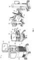
- a surgical robotic system 10 includes a control tower 20, which is connected to all of the components of the surgical robotic system 10 including a surgical console 30 and one or more robotic arms 40.
- Each of the robotic arms 40 includes a surgical instrument 50 and instrument drive unit 52 removably coupled thereto.
- Each of the robotic arms 40 is also coupled to and supported on a movable robotic arm cart 60.
- the surgical instrument 50 is configured for use during minimally invasive surgical procedures.
- the surgical instrument 50 may be configured for open surgical procedures.
- the surgical instrument 50 may be an endoscope, such as an endoscopic camera 51, configured to provide a video feed for the user.
- the surgical instrument 50 may be an electrosurgical forceps configured to seal tissue by compressing tissue between jaw members and applying electrosurgical current thereto.
- the surgical instrument 50 may be a surgical stapler including a pair of jaws configured to grasp and clamp tissue while deploying a plurality of tissue fasteners, e.g., staples, and cutting stapled tissue.
- One of the robotic arms 40 may include the endoscopic camera 51 configured to capture video of the surgical site.
- the endoscopic camera 51 may be a stereoscopic endoscope configured to capture two side-by-side (i.e., left and right) images of the surgical site to produce a video stream of the surgical scene.
- the endoscopic camera 51 is coupled to a video processing device 56, which may be disposed within the control tower 20.
- the video processing device 56 may be any computing device as described below configured to receive the video feed from the endoscopic camera 51 perform the image processing based on the depth estimating algorithms of the disclosure and output the processed video stream.
- the surgical console 30 includes a first display 32, which displays a video feed of the surgical site provided by camera 51 of the surgical instrument 50 disposed on the robotic arms 40, and a second display 34, which displays a user interface for controlling the surgical robotic system 10.
- the first and second displays 32 and 34 are touchscreens allowing for displaying various graphical user inputs.
- the surgical console 30 also includes a plurality of user interface devices, such as foot pedals 36 and a pair of handle controllers 38a and 38b which are used by a user to remotely control robotic arms 40.
- the surgical console further includes an armrest 33 used to support clinician's arms while operating the handle controllers 38a and 38b.
- the control tower 20 includes a display 23, which may be a touchscreen, and outputs on the graphical user interfaces (GUIs).
- GUIs graphical user interfaces
- the control tower 20 also acts as an interface between the surgical console 30 and one or more robotic arms 40.
- the control tower 20 is configured to control the robotic arms 40, such as to move the robotic arms 40 and the corresponding surgical instrument 50, based on a set of programmable instructions and/or input commands from the surgical console 30, in such a way that robotic arms 40 and the surgical instrument 50 execute a desired movement sequence in response to input from the foot pedals 36 and the handle controllers 38a and 38b.
- Each of the control tower 20, the surgical console 30, and the robotic arm 40 includes a respective computer 21, 31, 41.
- the computers 21, 31, 41 are interconnected to each other using any suitable communication network based on wired or wireless communication protocols.
- Suitable protocols include, but are not limited to, transmission control protocol/internet protocol (TCP/IP), datagram protocol/internet protocol (UDP/IP), and/or datagram congestion control protocol (DCCP).
- Wireless communication may be achieved via one or more wireless configurations, e.g., radio frequency, optical, Wi-Fi, Bluetooth (an open wireless protocol for exchanging data over short distances, using short length radio waves, from fixed and mobile devices, creating personal area networks (PANs), ZigBee ® (a specification for a suite of high level communication protocols using small, low-power digital radios based on the IEEE 122.15.4-2003 standard for wireless personal area networks (WPANs)).
- wireless configurations e.g., radio frequency, optical, Wi-Fi, Bluetooth (an open wireless protocol for exchanging data over short distances, using short length radio waves, from fixed and mobile devices, creating personal area networks (PANs), ZigBee ® (a specification for a suite of high level communication protocols using small, low-power digital radios based on the IEEE 122.15.4-2003 standard for wireless personal area networks (WPANs)).
- PANs personal area networks
- ZigBee ® a specification for a suite of high level communication protocols using small, low-power
- the computers 21, 31, 41 may include any suitable processor (not shown) operably connected to a memory (not shown), which may include one or more of volatile, non-volatile, magnetic, optical, or electrical media, such as read-only memory (ROM), random access memory (RAM), electrically-erasable programmable ROM (EEPROM), non-volatile RAM (NVRAM), or flash memory.
- the processor may be any suitable processor (e.g., control circuit) adapted to perform the operations, calculations, and/or set of instructions described in the present disclosure including, but not limited to, a hardware processor, a field programmable gate array (FPGA), a digital signal processor (DSP), a central processing unit (CPU), a microprocessor, and combinations thereof.
- the robotic arm 40 also includes a plurality of manual override buttons 53 disposed on the instrument drive unit 52 and the setup arm 62, which may be used in a manual mode. The user may press one or more of the buttons 53 to move the component associated with the button 53.
- the surgical robotic system 10 includes an aspect of a robotic arm cart 100 configured for supporting the robotic arm 40 ( FIG. 1 ) thereon and for transporting the robotic arm 40 to select locations within and/or outside of an operating room "OR.”
- the robotic arm cart 100 is configured to transition between a first state ("S1"), in which the robotic arm cart 100 assumes an enlarged footprint, and a second state "S2" in which the robotic arm cart 100 assumes a reduced footprint relative to the first state "S 1."
- the footprint of the robotic arm cart 100 may be defined by a perimeter outlined by a plurality of wheels 102 of the robotic arm cart 100.
- the footprint in the first state "S1," the footprint may assume a trapezoidal shape or a first rectangular shape, and in the second state “S2" the footprint may assume a second rectangular shape that is narrower than the first rectangular shape.
- Other suitable shapes for the footprints are also contemplated.
- the surgical robotic system 10 includes a docking station 150, such as, for example, a rail (tubular or non-tubular), and a plurality of robotic arm carts 100 positioned around the docking station 150 and each supporting a respective robotic arm 40.
- the docking station may be a rail that partially or entirely surrounds a surgical table "ST" and is affixed to a floor of the operating room "OR.”
- the docking station 150 may be a monolithic structure or a plurality of pieces that connect to one another around the surgical table "ST.”
- the docking station 150 may be tubular or otherwise define channels therethrough to permit the passage of electrical and/or data cables.
- the docking station 150 may incorporate data and/or power ports for connection with each of the robotic arm carts 100. It is contemplated that the cables of the docking station 150 may be connected to a power source within the docking station 150 or an external power source, such as the control tower 20. When the robotic arm carts 100 are electrically coupled to the docking station 150, and with the docking station electrically coupled to the control tower 20, there is a reduction in the number of cables running directly from each robotic arm cart 100 to the control tower 20.
- Each robotic arm cart 100 generally includes a base 104 for supporting the robotic arm 40 on an upper surface thereof, a plurality of supports or legs 106 extending downwardly from the base 104, and a docking stem 108 projecting radially outward form a front end portion 104a of the base 104 and configured to detachably couple the robotic arm cart 100 to the docking station 150, as will be described in further detail below.
- the base 104 of the robotic arm cart 100 may detachably couple the robotic arm 40 thereto via any suitable fastening mechanism, such as, for example, a threaded connection, a bayonet-type connection, a press-fit connection, etc.
- the surgical robotic arm 40 may be permanently affixed on the base 104.
- each of the legs 106 of the robotic arm cart 100 extend in parallel relation to the base 104 and the floor "F" such that the legs 106 flare outwardly relative to an outer periphery of the base 104 to inhibit tipping of the robotic arm cart 100.
- the legs 106 may extend at an oblique angle relative to the base 104 or perpendicular relative to the base 104.
- Each of the legs 106 has a first end 106a coupled to a respective corner of the base 104, and a second end 106b having a wheel or caster 102 coupled thereto to allow for a rolling motion of the robotic arm cart 100 along the floor "F" of the operating room "OR.”
- the first end 106a of the legs 106 may be rotatably coupled to the base 104 via a joint 110 to allow the legs 106 to rotate inwardly relative to the base 104 from an expanded state (shown in phantom in FIG. 3 ) to a contracted state ( FIG. 3 ).
- the joint 110 may be a screw joint configured to adjust both the height of the base 104 relative to the legs 106 and the rotational orientation of the legs 106 relative to the base 104.
- the joint 110 may first move only the base 104 in a vertical direction relative to the legs 106 until the wheels 102 thereof are unloaded (e.g., suspended from the floor "F") and thereafter rotate the legs 106 relative to the base 104 from the expanded state to the contracted state.
- the joint 110 may be replaced with a pin configured to move both perpendicularly relative to the base 104 (e.g., by actuation of a motor or by manually pushing down on the base 104 to overcome a threshold resistive force) to raise or lower the base 104 relative to the legs 106, and about a longitudinal axis of the pin to rotate the legs 106 between the contracted and expanded states.
- the legs 106 may be configured to extend or retract along a longitudinal axis thereof by including a series of connected telescopic tubes (not shown) that allow for the extension and retraction thereof. It is contemplated that due to the legs 106 being flared outwardly, when the legs 106 retract vertically, the footprint of the robotic arm cart 100 may be reduced.
- the first end 106a of the legs 106 may be movably coupled to the base 104 via a swivel joint, a sliding joint, or a combination thereof.
- the robotic arm cart 100 may include a single motor or motors (not explicitly shown) that receive power from a battery of the robotic arm cart 100 or an external power source (e.g., from the docking station 150) and which drive the movement of the legs 106 relative to the base 104.
- the motors may be electric, pneumatic, hydraulic, etc.
- an operator may manually move the legs 106 between the expanded and contracted states via a mechanical actuation of, for example, the foot pedals 36 or the handle controllers 38a and 38b ( FIG. 1 ).
- the legs 106 and the wheels 102 thereof are positioned radially outward of the outer periphery of the base 104 (shown in phantom in FIG. 3 ).
- the contracted state FIG.
- the legs 106 and wheels 102 thereof are positioned adjacent the outer periphery of the base 104, and in some instances, underneath the base 104. As such, the adjustability of the legs 106 allows for a change in the overall footprint of the robotic arm cart 100 from an enlarged state to a reduced state. While four legs 106 are shown, it is contemplated that the robotic arm cart 100 may include more or less than four legs 106.
- the robotic arm cart 100 further includes an auxiliary leg or support 112 extending downwardly from a rear end portion 104b of the base 104.
- the auxiliary leg 112 and the docking stem 108 are positioned at opposite end portions 104a, 104b of the base 104.
- the auxiliary leg 112 has a bottom end supporting a wheel 114, such as, for example, an omni wheel that allows for rolling of the robotic arm cart 100 in a plurality of directions.
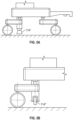
- the bottom end of the auxiliary leg 100 may have a stopper 114' ( FIG. 5A ) that resists motion of the robotic arm cart 100 along the floor "F," a single axis wheel 114" ( FIG.
- the docking stem 108 of the robotic arm cart 100 includes a hooked end 116 and a boss 118 extending downwardly from the docking stem 108.
- the docking station 150 defines a channel 152 in an upper surface thereof that extends along the length of the docking station 150.
- the channel 152 is configured for receipt of the boss 118 of the docking stem 108 such that the hooked end 116 and the boss 118 of the docking station 108 secure to the docking station 150 and inhibit movement of the robotic arm cart 100 in directions toward or away from the docking station 150.
- the hooked end 116 of the docking stem 108 may include an electrical plug (not explicitly shown) for electrically connecting with electrical cables of the docking station 150.
- the engagement between the docking stem 108 and the docking station 150 may allow for sliding movement of the robotic arm cart 100 relative to and along the docking station 150 to adjust a position of the surgical robotic arm 40 relative to the surgical table "ST" ( FIG. 3 ).
- a stabilizing arm 120 may be provided that secures the base 104 of the robotic arm cart 100 to the docking station 50 and prohibits sliding of the robotic arm cart 100 relative to the docking station 150.
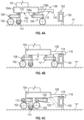
- the robotic arm cart 100 In operation, with a surgical robotic arm 40 secured to the base 104 of the robotic arm cart 100, the robotic arm cart 100 is rolled to a select location along the surgical table "ST" ( FIG. 3 ) with the docking stem 108 adjacent and facing the docking station 150, as shown in FIG. 4A .
- the robotic arm cart 100 is moved toward the docking station 150 until the hooked end 116 of the docking stem 108 is suspended above the docking station 150 with the boss 118 of the docking stem 108 aligned with the channel 152 of the docking station 150, as shown in FIG. 4B .
- the motors in the robotic arm cart 100 are actuated to rotate the joints 110 whereby the base 104 is lowered relative to the legs 106 along a vertical axis "V" ( FIG. 4B ).
- the robotic arm cart 100 remains capable of sliding along and relative to the docking station 150 (and the surgical table "ST"), but is prohibited from rotating relative to the docking station 150, tilting, or moving in a direction toward or away from the docking station 150.
- the stabilizing arm 120 FIG. 4C may be connected to the base 104 and the docking station 150.
- the continued rotation of the joints 110 rotates the legs 106 therewith about a single axis "V" ( FIG. 4B ) defined through the joint 110. Accordingly, the wheels 102 of the legs 106 are rotated inwardly toward the base 104 from the expanded state ( FIGS. 4A and 4B ) to the contracted state ( FIG. 4C ) to reduce the footprint of the robotic arm cart 100.
- a single actuation of the motors of the robotic arm cart 100 simultaneously lowers the base 104 relative to the legs 106 and rotates the legs 106 relative to the base 104.
- a plurality of the robotic arm carts 100 may be positioned in close proximity with one another along the surgical table "ST" while remaining stable due to the connection between the docking stem 108 and the docking station 150.
- the reduced footprint configuration of the robotic arm cart 100 may also be used when storing the robotic arm cart 100. It is contemplated that in surgical situations where space in the operating room "OR" is plentiful, for example, when only a single robotic arm cart 100 is needed, or during transport, the wheels 102 of the legs 106 may be locked and the legs 106 may remain in the expanded position. Since the robotic arm cart 100 will be more stable with the legs 106 in the expanded position, engagement of the docking stem 108 with the docking station 150 may not be needed.
- the movement of the legs 106 may reduce a width of the robotic arm cart 100 (defined in a direction parallel with the docking station 150) while maintaining, increasing, or decreasing a length of the robotic arm cart 10 (defined in a direction perpendicularly with the docking station 150). It is further contemplated that the movement of the legs 106 may adjust the shape of the robotic arm cart 100 (e.g., from a square to a rectangle).
- FIGS. 6A-6C another type of robotic arm cart 200 of the surgical robotic system of FIG. 1 is shown.
- the robotic arm cart 200 is similar to and may include any of the features of the robotic arm cart 100 of FIGS. 4A-4C except as explicitly contradicted below.
- the robotic arm cart 200 generally includes a base 204 for supporting a robotic arm 40 thereon, a plurality of legs 206 coupled to and extending downwardly from the base 204, and a docking stem 208 projecting from the base 204.
- the legs 206 have opposing first and second ends 206a, 206b with the first end 206a coupled to the base 204 and the second end 206b supporting a caster 202.
- One or more of the legs 206 is coupled to the base 204 via a respective joint 210 (e.g., a pivot joint) to allow for rotational movement of the legs 206 from an expanded state ( FIGS. 6A, 6B ) to a contracted state ( FIG. 6C ).
- the joint 210 may be powered by a motor (not explicitly shown) or the legs 206 may be manually rotated relative to the base 204.
- the legs 206 may be coupled to the base 204 via a sliding joint, a swivel joint, a screw joint, or the like.
- the casters 202 are configured to rotate 90 degrees about a vertical axis "Y" ( FIG. 6A ) between a first orientation ( FIGS. 6A, 6B ) in which a rolling axis (extending through the page) of the casters 202 is parallel with the docking station 150, and a second orientation ( FIG. 6C ) in which the rolling axis of the casters 202 is perpendicular to the docking station 150. It is contemplated that the casters 202 may be rotatable 360 degrees in either direction.
- the docking stem 208 has a hooked distal end 216, and a proximal end 218 slidably coupled to the base 204 such that a vertical position of the stem 208 relative to the base 204 is adjustable.
- the robotic arm cart 200 In operation, with a surgical robotic arm 40 secured to the base 204 of the robotic arm cart 200, the robotic arm cart 200 is rolled to a select location along the surgical table with the docking stem 208 adjacent and facing the docking station 150, as shown in FIG. 6A .
- the robotic arm cart 200 is moved toward the docking station 150 until the hooked distal end 216 of the docking stem 208 is suspended above the docking station 150, as shown in FIG. 6B .
- the stem 208 is translated along a vertical axis (e.g., via actuation of a motor) relative to the base 204 and toward the floor to engage the hooked distal end 216 of the stem 208 with the docking station 150.
- the legs 206 are moved (e.g., rotated) from the expanded state to the contracted state ( FIG. 6C ) to reduce the footprint of the robotic arm cart 200.
- the casters 202 of the robotic arm cart 200 may be rotated from the first rotational orientation ( FIG. 6B ) to the second rotational orientation ( FIG. 6C ) to allow for rolling motion of the robotic arm cart 200 relative to and along the docking station 150.
- FIGS. 7A-7C another type of robotic arm cart 300 and docking station 350 of the surgical robotic system 10 of FIG. 1 is shown.
- the robotic arm cart 300 is similar to and may include any of the features of the robotic arm cart 100 of FIGS. 4A-4C except as explicitly contradicted below, and the docking station 350 is similar to and may include any of the features of the docking station 150 of FIGS. 4A-4C .
- the docking station 350 is secured to the floor “F" of an operating room and surrounds a surgical table ( FIG. 3 ).
- the docking station 350 is plate-like and defines an elongated channel 352 that extends along the length thereof.
- the docking station 350 may include a metal or magnet (not explicitly shown) positioned within the channel 352. It is contemplated that electric power and communication may be provided from the docking station 350 to the cart 300 by means of contact free transmission (e.g., near field communication, electromagnetic power transfer, etc.).
- the electrical interface may also provide for identification of which robotic arm cart 100 (e.g., based on a number in the system or a serial number) is connected to the docking station 300.
- the docking station 350 may integrate a measurement system configured to identify the position of each connected cart 300 along the docking station 350 to provide input for setup planning, optimization, and/or strategies for arm-to-arm collisions.
- the robotic arm cart 300 generally includes a base 304 for supporting a robotic arm 40 thereon, a plurality of legs 306 coupled to and extending downwardly from the base 304, an auxiliary leg 312 projecting downwardly from the base 304, and a docking stem 308 projecting from the base 304.
- the legs 306 have opposing first and second ends with the first end coupled to the base 304 and the second end supporting a wheel 302 (e.g., a caster).
- One or more of the legs 306 is coupled to the base 304 via a respective joint 310 (e.g., a screw joint) to allow for both rotational movement of the legs 306 from an expanded state ( FIGS. 7A, 7B ) to a contracted state ( FIG.
- the joint 310 may be powered by a motor (not explicitly shown) or the legs 306 may be manually rotated relative to the base 304.
- the legs 306 may be coupled to the base 304 via a sliding joint, a swivel joint, a screw j oint, or the like.
- the docking stem 308 has a vertical segment 308a extending downwardly from the base 304 and a horizontal segment 308b extending perpendicularly from the vertical segment 308a such that the docking stem 308 has an L-shape. Other configurations of the docking stem 308 are also contemplated.
- the horizontal segment 308b has a magnetic element 316 secured to an end thereof configured for receipt in the channel 352 of the docking station 350.
- the robotic arm cart 300 In operation, with a surgical robotic arm 40 secured to the base 304 of the robotic arm cart 300, the robotic arm cart 300 is rolled to a select location along the surgical table with the docking stem 308 adjacent and facing the docking station 350, as shown in FIG. 7A .
- the robotic arm cart 300 is rolled onto a ramp 354 of the docking station 350 until the magnetic element 316 of the docking stem 308 is suspended above the channel 352 of the docking station 350, as shown in FIG. 7B .
- the motors in the robotic arm cart 300 are actuated to rotate the joints 310 whereby the base 304 is lowered relative to the legs 306 along a vertical axis.
- the robotic arm cart 300 remains capable of sliding along and relative to the docking station 350, but is prohibited from rotating relative to the docking station 350, tilting, or moving toward or away from the docking station 350.
- a plurality of magnetic elements 316 may be provided with each having a different magnetic strength. In this way, in surgical situation where no movement of the robotic arm cart 300 relative to the docking station 350 is desired, a stronger magnetic element 316 may be selected.
- the continued rotation of the joints 310 rotates the legs 306 therewith about a single axis defined through the respective joint 310. Accordingly, the wheels 302 of the legs 306 are rotated inwardly toward the base 304 from the expanded state ( FIGS. 7A and 7B ) to the contracted state ( FIG. 7C ) to reduce the footprint of the robotic arm cart 300.
- a single actuation of the motors of the robotic arm cart 300 simultaneously lowers the base 304 relative to the legs 306 and rotates the legs 306 relative to the base 304.
- FIGS. 8A-8C another type of robotic arm cart 400 and docking station 450 of the surgical robotic system 10 of FIG. 1 is shown.
- the robotic arm cart 400 is similar to and may include any of the features of the robotic arm cart 200 of FIGS. 6A-6C except as explicitly contradicted below, and the docking station 450 is similar to and may include any of the features of the docking station 350 of FIGS. 7A-7C .
- the docking station 450 is secured to a floor "F" of an operating room and surrounds a surgical table ( FIG. 3 ).
- the docking station 450 has a ramped portion 454 and a generally planar upper surface defining an elongated channel 452 that extends along the length thereof.
- the docking station 450 may be metallic or magnetic.
- the robotic arm cart 400 generally includes a base 404 for supporting a robotic arm 40 thereon, a plurality of legs 406 coupled to and extending downwardly from the base 404, and a docking stem 408 projecting from the base 404.
- the legs 406 have opposing first and second ends with the first end coupled to the base 404 and the second end supporting a caster 402.
- the docking stem 408 has a vertical segment 408a extending downwardly from the base 404 and a horizontal segment 408b extending perpendicularly from the vertical segment 408a such that the docking stem 408 has an L-shape.
- the vertical segment 408a is slidably coupled to the base 408 to allow for an adjustment of a vertical position of the horizontal segment 408b relative to the base 404.
- the horizontal segment 408b has a magnetic element 416 secured to an end thereof configured for magnetic coupling with the docking station 450.
- the robotic arm cart 400 In operation, with a surgical robotic arm 40 secured to the base 404 of the robotic arm cart 400, the robotic arm cart 400 is rolled to a select location along the docking station 450, as shown in FIG. 8A .
- the front wheels 402 of the robotic arm cart 400 are rolled onto the ramp portion 454 of the docking station 450, as shown in FIG. 8B , and into the channel 452 of the docking station 450. It is contemplated that the channel 452 has a width sufficient to accommodate the front wheels 402 therein in any rotational orientation of the wheels 402.
- the wheels 402 may be rotated from a first rotational orientation ( FIGS. 8A, 8B ) to a second rotational orientation ( FIG. 8C ) to allow for rolling motion of the robotic arm cart 400 relative to and along the docking station 450.
- the docking stem 408 is translated along a vertical axis (e.g., via actuation of a motor) relative to the base 404 and toward the floor "F" to engage the magnetic element 416 of the docking stem 408 with the docking station 450.
- the rear legs 406 are moved (e.g., pivoted) inwardly from the expanded state to the contracted state to reduce the footprint of the robotic arm cart 400.
- the docking stations may integrate electrical interfaces along their length to which the carts may connect for communication and power supply.
- the electrical interface may be formed by multiple elongated electrical tracks over the length of the docking station (e.g., on the bottom surface of the docking station) and electrical spring contacts (e.g., in the docking stems).
- the lateral sides of the carts may have additional docking mechanisms such that carts that are placed adjacent one another may be connected to further improve mechanical stability.
- the legs of the carts may be removably attached to the robotic arm carts.
- the footprint of the robotic arm carts may be automatically changed by the surgical robotic system during a procedure based on the changing dynamics and external loads on the robot arm to configure a stable but small footprint.
- An active control loop may be based on the commanded motion of the robot, measured dynamics of the robot, and measured external loads on the robot (e.g., user interaction) to generate commanded positions for the movable legs in order to ensure/improve stability.
- the steering angle joint of the casters are designed/controlled in a way that allows for such changes of the footprint, either by having sufficient trail or being actively controlled by motors.
- the surgical system may include a safe mode in the event of a defect, power-loss, surgical conversion, etc.
- the safe mode may include switching to a configuration of the robotic arm carts that allows for quickly removing the carts from their positions to evacuate the patient or, for example, creating the most stable wheelbase.
- the surgical system may be configured to automatically change the configuration of the robotic arm carts into the enlarged footprint (e.g., via spring loading) by having redundancy (e.g., battery power), and/or having manual interfaces to override the mechanism (e.g., foot pedals).
- the described techniques may be implemented in hardware, software, firmware, or any combination thereof. If implemented in software, the functions may be stored as one or more instructions or code on a computer-readable medium and executed by a hardware-based processing unit.
- Computer-readable media may include non-transitory computer-readable media, which corresponds to a tangible medium such as data storage media (e.g., RAM, ROM, EEPROM, flash memory, or any other medium that can be used to store desired program code in the form of instructions or data structures and that can be accessed by a computer).
- processors such as one or more digital signal processors (DSPs), general purpose microprocessors, application specific integrated circuits (ASICs), field programmable logic arrays (FPGAs), or other equivalent integrated or discrete logic circuitry.
- DSPs digital signal processors
- ASICs application specific integrated circuits
- FPGAs field programmable logic arrays
- processors may refer to any of the foregoing structure or any other physical structure suitable for implementation of the described techniques. Also, the techniques could be fully implemented in one or more circuits or logic elements.
Landscapes
- Health & Medical Sciences (AREA)
- Engineering & Computer Science (AREA)
- Surgery (AREA)
- Life Sciences & Earth Sciences (AREA)
- Medical Informatics (AREA)
- Biomedical Technology (AREA)
- Heart & Thoracic Surgery (AREA)
- Nuclear Medicine, Radiotherapy & Molecular Imaging (AREA)
- Molecular Biology (AREA)
- Animal Behavior & Ethology (AREA)
- General Health & Medical Sciences (AREA)
- Public Health (AREA)
- Veterinary Medicine (AREA)
- Robotics (AREA)
- Mechanical Engineering (AREA)
- Manipulator (AREA)
Abstract
A surgical robotic system includes a robotic arm cart for supporting a robotic arm, and a docking station configured to be secured to an operating room floor around a surgical table. The robotic arm cart has a plurality of legs having wheels for facilitating movement of the robotic arm cart along the floor of the operating room. The robotic arm cart is configured to transition from an enlarged footprint state to a reduced footprint state. When the robotic arm cart is in the reduced footprint state, the robotic arm cart may be connected to the docking station to provide stability to the robotic arm cart.
Description
- The present application claims the benefit of and priority to
U.S. Provisional Patent Application Serial No. 63/308,553, filed on February 10, 2022 - The present technology is generally related to surgical robotic systems used in minimally invasive medical procedures.
- Robotic surgical systems are used in minimally invasive medical procedures because of their increased accuracy and expediency relative to handheld surgical instruments. In these robotic surgical systems, a robotic arm may support a surgical instrument having an end effector mounted thereto by a wrist assembly. In operation, the robotic arm is moved to a position over a patient and then guides the surgical instrument into a small incision via a surgical port or a natural orifice of a patient to position the end effector at a work site within the patient's body.
- Some robotic surgical systems employ a cart to support the robotic arm and allow a clinician to move the robotic arm to different locations within the operating room. During a surgical procedure, it would be desirable for the cart to be held in a stationary position without occupying too much space within the operating room.
- In one aspect of the disclosure, a robotic arm cart is provided that includes a base for supporting a robotic arm thereon, and a plurality of legs coupled to the base and configured to support the base above a surface. The robotic arm cart is configured to transition between a first state in which the robotic arm cart assumes a first footprint and a second state in which the robotic arm cart assumes a second footprint that is different from the first footprint.
- In aspects, one of the legs may be movably coupled to the base such that the leg is configured to move relative to the base between a first position, in which the robotic arm cart assumes the first footprint, and a second position, in which the robotic arm cart assumes the second footprint.
- In aspects, the leg may be configured to pivot, swivel, and/or slide relative to the base between the first and second positions.
- In aspects, each of the legs may be configured to move relative to the base between the first position and the second position.
- In aspects, the legs may be configured to both rotate relative to the base between the first and second positions and translate along respective longitudinal axes thereof to lower the base relative to the surface.
- In aspects, the robotic arm cart may further include a plurality of wheels respectively coupled to an end of the plurality of legs.
- In aspects, the wheels may be positioned closer to an outer periphery of the base when the robotic arm cart is in the second state than when the robotic arm cart is in the first state.
- In aspects, the first footprint may have a larger perimeter than the second footprint.
- In aspects, the end of each of the legs may be configured to move relative to the base to move the wheels between a position further from an outer periphery of the base to a position closer to the outer periphery of the base.
- In aspects, the robotic arm cart may further include a docking stem extending from the base and configured to engage a docking station.
- In aspects, the robotic arm cart may further include an auxiliary leg extending downwardly from the base. The auxiliary leg may be configured to support the base above the surface when the robotic arm cart transitions to the second state.
- In aspects, the auxiliary leg may have an end supporting a wheel or a foot thereon, and the legs may be configured to move vertically relative to the base whereby the base is lowered toward the surface and the docking stem engages the docking station. In addition, the wheel or foot of the auxiliary leg may contact the surface and support the base above the surface.
- In accordance with another aspect of the disclosure, a surgical robotic system is provided that includes a docking station configured to be positioned on a floor of an operating room and adjacent a surgical table, and a robotic arm cart that includes a base for supporting a robotic arm thereon, a docking stem coupled to the base and configured to engage the docking station to stabilize the robotic arm cart, a plurality of legs coupled to the base and configured to support the base above the floor, and a plurality of wheels respectively coupled to the legs. One or more of the legs is configured to move relative to the base to transition the robotic arm cart between a first state in which the robotic arm cart assumes an enlarged footprint and a second state in which the robotic arm cart assumes a reduced footprint relative to the first state.
- In aspects, the docking station may be configured to be seated on the floor of the operating room and to at least partially surround the surgical table. The docking stem of the robotic arm cart may be configured to move vertically relative to the base to selectively engage the docking station.
- In aspects, the docking station may be a plate configured to magnetically couple to the docking stem.
- In aspects, the docking stem may be configured to engage the docking station in response to the leg moving relative to the base from an extended position to a retracted position.
- In aspects, the robotic arm cart may further include an auxiliary leg extending downwardly from the base. The auxiliary leg may be configured to support the base above the floor of the operating room when the leg moves relative to the base from the extended position to the retracted position.
- In aspects, the docking station may be a rail defining a channel therein configured for receipt of one of the wheels.
- In aspects, the docking stem may include a magnet, and the docking stem may be configured to move vertically relative to the base to engage the magnet of the docking stem with the rail.
- In accordance with further aspects of the disclosure, a robotic arm cart is provided that includes a base for supporting a robotic arm thereon, a docking stem coupled to the base and configured to attach to a docking station in an operating room, a plurality of legs coupled to the base and configured to support the base above a floor of the operating room, and a plurality of wheels respectively coupled to the legs. The legs are configured to transition from an expanded state to a contracted state relative to the base to change a configuration of the robotic arm cart.
- Further details and exemplary aspects of the disclosure are described in more detail below with reference to the appended figures.
- As used herein, the terms parallel and perpendicular are understood to include relative configurations that are substantially parallel and substantially perpendicular up to about + or - 10 degrees from true parallel and true perpendicular.
- Embodiments of the disclosure are described herein with reference to the accompanying drawings, wherein:
-
FIG. 1 is a schematic illustration of a surgical robotic system including a control tower, a console, and one or more surgical robotic arms supported on a robotic arm cart; -
FIG. 2 is a top view of a plurality of robotic arm carts of the surgical robotic system ofFIG. 1 positioned alongside a surgical table; -
FIG. 3 is a top view illustrating a plurality of robotic arm carts coupled to a docking station with each having a reduced footprint; -
FIG. 4A is a side view illustrating one of the robotic arm carts ofFIG. 3 including a stem thereof disconnected from the docking station ofFIG. 3 ; -
FIG. 4B is a side view illustrating the robotic arm cart ofFIG. 4A with the stem thereof shown being attached to the docking station; -
FIG. 4C is a side view illustrating the robotic arm cart ofFIG. 4B with a stabilizing arm securing the robotic arm cart to the docking station; -
FIG. 5A is a side view illustrating another robotic arm cart including a docking stem, a plurality of wheeled legs, and an auxiliary leg having a foot; -
FIG. 5B is a partial side view illustrating another robotic arm cart including a wheeled leg and an auxiliary leg having a wheel; -
FIG. 6A is a side view illustrating another robotic arm cart including a plurality of wheeled legs and a docking stem, which is shown disconnected from the docking station ofFIG. 3 ; -
FIG. 6B is a side view illustrating the robotic arm cart ofFIG. 6A with the stem thereof shown being connected to the docking station; -
FIG. 6C is a side view illustrating the robotic arm cart ofFIG. 6B with one of the legs in a retracted state and the wheels thereof rotated 90 degrees; -
FIG. 7A is a side view illustrating another robotic arm cart including a plurality of wheeled legs, an auxiliary leg supporting a wheel, and a docking stem shown disconnected from a docking rail; -
FIG. 7B is a side view illustrating the robotic arm cart ofFIG. 7A being positioned on the docking rail; -
FIG. 7C is a side view illustrating the robotic arm cart ofFIG. 7B with the wheeled legs in a retracted state, the auxiliary leg engaged with the floor, and the stem lowered into engagement with the docking rail; -
FIG. 8A is a side view illustrating yet another robotic arm cart including a plurality of wheeled legs and a docking stem shown disconnected from a docking rail; -
FIG. 8B is a side view illustrating the robotic arm cart ofFIG. 8A being positioned on the docking rail; and -
FIG. 8C is a side view illustrating the robotic arm cart ofFIG. 8B with the stem lowered into engagement with the docking rail and the wheels being rotated 90 degrees. - Embodiments of the disclosed surgical robotic system are described in detail with reference to the drawings, in which like reference numerals designate identical or corresponding elements in each of the several views. As used herein the term "distal" refers to that portion of the surgical robotic system and robotic arm cart thereof that is closer to a floor of an operating room, while the term "proximal" refers to that portion of the surgical robotic system and robotic arm cart thereof that is further from the floor.
- In robotic surgery, the position stability of a base of a robotic arm is important for the accuracy of the arm. Any change of the position or orientation ("pose") of the robot base transfers to the pose of the end-effector and thus impacts the accuracy of the procedure. Therefore, the supporting structures (e.g., the robotic arm cart) on which a robot is mounted should have high position stability. For carts, this drives the size of the carts to achieve the following: 1. The cart is rigid; and 2. The footprint of the cart (e.g., the perimeter outlined by the casters) is large enough to provide stability. Achieving the last aspect may be challenging because the carts are preferably close to the patient and the space around an operating room bed is constrained and valuable for access to the patient, especially when multiple carts need to be positioned as close as possible to each other. However, reducing the footprint of a cart renders the cart more susceptible to tipping over.
- This disclosure is based on a variable footprint of the cart so that for transport and for applications where space is not constrained (e.g., single arm applications), a larger footprint is available to provide sufficient stability against tip-over; and for applications where space is a challenge (e.g., multi arm applications), the footprint of the cart may be reduced and stability reestablished by docking the cart to a frame around the operating room bed. This approach allows for a high flexibility in relation to a number of arms in an application, the smallest possible footprint, and low modification effort of the operating room.
- With reference to
FIG. 1 , a surgicalrobotic system 10 includes acontrol tower 20, which is connected to all of the components of the surgicalrobotic system 10 including asurgical console 30 and one or morerobotic arms 40. Each of therobotic arms 40 includes asurgical instrument 50 andinstrument drive unit 52 removably coupled thereto. Each of therobotic arms 40 is also coupled to and supported on a movablerobotic arm cart 60. - The
surgical instrument 50 is configured for use during minimally invasive surgical procedures. In embodiments, thesurgical instrument 50 may be configured for open surgical procedures. In embodiments, thesurgical instrument 50 may be an endoscope, such as anendoscopic camera 51, configured to provide a video feed for the user. In further embodiments, thesurgical instrument 50 may be an electrosurgical forceps configured to seal tissue by compressing tissue between jaw members and applying electrosurgical current thereto. In yet further embodiments, thesurgical instrument 50 may be a surgical stapler including a pair of jaws configured to grasp and clamp tissue while deploying a plurality of tissue fasteners, e.g., staples, and cutting stapled tissue. - One of the
robotic arms 40 may include theendoscopic camera 51 configured to capture video of the surgical site. Theendoscopic camera 51 may be a stereoscopic endoscope configured to capture two side-by-side (i.e., left and right) images of the surgical site to produce a video stream of the surgical scene. Theendoscopic camera 51 is coupled to avideo processing device 56, which may be disposed within thecontrol tower 20. Thevideo processing device 56 may be any computing device as described below configured to receive the video feed from theendoscopic camera 51 perform the image processing based on the depth estimating algorithms of the disclosure and output the processed video stream. - The
surgical console 30 includes afirst display 32, which displays a video feed of the surgical site provided bycamera 51 of thesurgical instrument 50 disposed on therobotic arms 40, and asecond display 34, which displays a user interface for controlling the surgicalrobotic system 10. The first andsecond displays - The
surgical console 30 also includes a plurality of user interface devices, such asfoot pedals 36 and a pair ofhandle controllers robotic arms 40. The surgical console further includes an armrest 33 used to support clinician's arms while operating thehandle controllers - The
control tower 20 includes adisplay 23, which may be a touchscreen, and outputs on the graphical user interfaces (GUIs). Thecontrol tower 20 also acts as an interface between thesurgical console 30 and one or morerobotic arms 40. In particular, thecontrol tower 20 is configured to control therobotic arms 40, such as to move therobotic arms 40 and the correspondingsurgical instrument 50, based on a set of programmable instructions and/or input commands from thesurgical console 30, in such a way thatrobotic arms 40 and thesurgical instrument 50 execute a desired movement sequence in response to input from thefoot pedals 36 and thehandle controllers - Each of the
control tower 20, thesurgical console 30, and therobotic arm 40 includes arespective computer computers - The
computers robotic arm 40 also includes a plurality ofmanual override buttons 53 disposed on theinstrument drive unit 52 and thesetup arm 62, which may be used in a manual mode. The user may press one or more of thebuttons 53 to move the component associated with thebutton 53. - With reference to
FIG. 2 , the surgicalrobotic system 10 includes an aspect of arobotic arm cart 100 configured for supporting the robotic arm 40 (FIG. 1 ) thereon and for transporting therobotic arm 40 to select locations within and/or outside of an operating room "OR." Generally, therobotic arm cart 100 is configured to transition between a first state ("S1"), in which therobotic arm cart 100 assumes an enlarged footprint, and a second state "S2" in which therobotic arm cart 100 assumes a reduced footprint relative to the first state "S 1." The footprint of therobotic arm cart 100 may be defined by a perimeter outlined by a plurality ofwheels 102 of therobotic arm cart 100. In aspects, in the first state "S1," the footprint may assume a trapezoidal shape or a first rectangular shape, and in the second state "S2" the footprint may assume a second rectangular shape that is narrower than the first rectangular shape. Other suitable shapes for the footprints are also contemplated. - With reference to
FIG. 3-4C , the surgicalrobotic system 10 includes adocking station 150, such as, for example, a rail (tubular or non-tubular), and a plurality ofrobotic arm carts 100 positioned around thedocking station 150 and each supporting a respectiverobotic arm 40. The docking station may be a rail that partially or entirely surrounds a surgical table "ST" and is affixed to a floor of the operating room "OR." In aspects, thedocking station 150 may be a monolithic structure or a plurality of pieces that connect to one another around the surgical table "ST." Thedocking station 150 may be tubular or otherwise define channels therethrough to permit the passage of electrical and/or data cables. Thedocking station 150 may incorporate data and/or power ports for connection with each of therobotic arm carts 100. It is contemplated that the cables of thedocking station 150 may be connected to a power source within thedocking station 150 or an external power source, such as thecontrol tower 20. When therobotic arm carts 100 are electrically coupled to thedocking station 150, and with the docking station electrically coupled to thecontrol tower 20, there is a reduction in the number of cables running directly from eachrobotic arm cart 100 to thecontrol tower 20. - Each
robotic arm cart 100 generally includes abase 104 for supporting therobotic arm 40 on an upper surface thereof, a plurality of supports orlegs 106 extending downwardly from thebase 104, and adocking stem 108 projecting radially outward form afront end portion 104a of thebase 104 and configured to detachably couple therobotic arm cart 100 to thedocking station 150, as will be described in further detail below. Thebase 104 of therobotic arm cart 100 may detachably couple therobotic arm 40 thereto via any suitable fastening mechanism, such as, for example, a threaded connection, a bayonet-type connection, a press-fit connection, etc. In aspects, the surgicalrobotic arm 40 may be permanently affixed on thebase 104. - As best shown in
FIGS. 4A-4C , each of thelegs 106 of therobotic arm cart 100 extend in parallel relation to thebase 104 and the floor "F" such that thelegs 106 flare outwardly relative to an outer periphery of the base 104 to inhibit tipping of therobotic arm cart 100. In other aspects, thelegs 106 may extend at an oblique angle relative to the base 104 or perpendicular relative to thebase 104. Each of thelegs 106 has afirst end 106a coupled to a respective corner of thebase 104, and asecond end 106b having a wheel orcaster 102 coupled thereto to allow for a rolling motion of therobotic arm cart 100 along the floor "F" of the operating room "OR." - The
first end 106a of thelegs 106 may be rotatably coupled to thebase 104 via a joint 110 to allow thelegs 106 to rotate inwardly relative to the base 104 from an expanded state (shown in phantom inFIG. 3 ) to a contracted state (FIG. 3 ). For example, the joint 110 may be a screw joint configured to adjust both the height of the base 104 relative to thelegs 106 and the rotational orientation of thelegs 106 relative to thebase 104. As such, the joint 110 may first move only the base 104 in a vertical direction relative to thelegs 106 until thewheels 102 thereof are unloaded (e.g., suspended from the floor "F") and thereafter rotate thelegs 106 relative to the base 104 from the expanded state to the contracted state. In other aspects, the joint 110 may be replaced with a pin configured to move both perpendicularly relative to the base 104 (e.g., by actuation of a motor or by manually pushing down on the base 104 to overcome a threshold resistive force) to raise or lower thebase 104 relative to thelegs 106, and about a longitudinal axis of the pin to rotate thelegs 106 between the contracted and expanded states. In further aspects still, thelegs 106 may be configured to extend or retract along a longitudinal axis thereof by including a series of connected telescopic tubes (not shown) that allow for the extension and retraction thereof. It is contemplated that due to thelegs 106 being flared outwardly, when thelegs 106 retract vertically, the footprint of therobotic arm cart 100 may be reduced. In other aspects, thefirst end 106a of thelegs 106 may be movably coupled to thebase 104 via a swivel joint, a sliding joint, or a combination thereof. - The
robotic arm cart 100 may include a single motor or motors (not explicitly shown) that receive power from a battery of therobotic arm cart 100 or an external power source (e.g., from the docking station 150) and which drive the movement of thelegs 106 relative to thebase 104. The motors may be electric, pneumatic, hydraulic, etc. In aspects, an operator may manually move thelegs 106 between the expanded and contracted states via a mechanical actuation of, for example, thefoot pedals 36 or thehandle controllers FIG. 1 ). In the expanded state, thelegs 106 and thewheels 102 thereof are positioned radially outward of the outer periphery of the base 104 (shown in phantom inFIG. 3 ). In the contracted state (FIG. 3 ), thelegs 106 andwheels 102 thereof are positioned adjacent the outer periphery of thebase 104, and in some instances, underneath thebase 104. As such, the adjustability of thelegs 106 allows for a change in the overall footprint of therobotic arm cart 100 from an enlarged state to a reduced state. While fourlegs 106 are shown, it is contemplated that therobotic arm cart 100 may include more or less than fourlegs 106. - With continued reference to
FIGS. 4A-4C , therobotic arm cart 100 further includes an auxiliary leg orsupport 112 extending downwardly from arear end portion 104b of thebase 104. As such, theauxiliary leg 112 and thedocking stem 108 are positioned atopposite end portions base 104. Theauxiliary leg 112 has a bottom end supporting awheel 114, such as, for example, an omni wheel that allows for rolling of therobotic arm cart 100 in a plurality of directions. In other aspects, the bottom end of theauxiliary leg 100 may have a stopper 114' (FIG. 5A ) that resists motion of therobotic arm cart 100 along the floor "F," asingle axis wheel 114" (FIG. 5B ) that permits rolling motion of therobotic arm cart 100 along a single axis parallel to and along thedocking station 150, or a caster (not shown). Retraction of thelegs 106 in a vertical direction by the joint 110 lowers the base 104 relative to the floor "F" until theomni wheel 114 engages the floor "F" and thewheels 102 of thelegs 106 lift off the floor "F" such that theomni wheel 102 and thedocking stem 108 of therobotic arm cart 100 are the only components suspending the base 104 from the floor "F." - The docking stem 108 of the
robotic arm cart 100 includes ahooked end 116 and aboss 118 extending downwardly from thedocking stem 108. Thedocking station 150 defines achannel 152 in an upper surface thereof that extends along the length of thedocking station 150. Thechannel 152 is configured for receipt of theboss 118 of thedocking stem 108 such that thehooked end 116 and theboss 118 of thedocking station 108 secure to thedocking station 150 and inhibit movement of therobotic arm cart 100 in directions toward or away from thedocking station 150. Thehooked end 116 of thedocking stem 108 may include an electrical plug (not explicitly shown) for electrically connecting with electrical cables of thedocking station 150. It is contemplated that the engagement between thedocking stem 108 and thedocking station 150 may allow for sliding movement of therobotic arm cart 100 relative to and along thedocking station 150 to adjust a position of the surgicalrobotic arm 40 relative to the surgical table "ST" (FIG. 3 ). As shown inFIG. 4C , a stabilizingarm 120 may be provided that secures thebase 104 of therobotic arm cart 100 to thedocking station 50 and prohibits sliding of therobotic arm cart 100 relative to thedocking station 150. - In operation, with a surgical
robotic arm 40 secured to thebase 104 of therobotic arm cart 100, therobotic arm cart 100 is rolled to a select location along the surgical table "ST" (FIG. 3 ) with thedocking stem 108 adjacent and facing thedocking station 150, as shown inFIG. 4A . Therobotic arm cart 100 is moved toward thedocking station 150 until thehooked end 116 of thedocking stem 108 is suspended above thedocking station 150 with theboss 118 of thedocking stem 108 aligned with thechannel 152 of thedocking station 150, as shown inFIG. 4B . The motors in therobotic arm cart 100 are actuated to rotate thejoints 110 whereby thebase 104 is lowered relative to thelegs 106 along a vertical axis "V" (FIG. 4B ). - The continued lowering of the base 104 toward the
wheels 102 of thelegs 106 ultimately results in thewheel 114 of theauxiliary leg 112 engaging the floor "F" and thewheels 102 of thelegs 106 raising off the floor "F," as shown inFIG. 4C . Concurrently with thewheel 114 of theauxiliary leg 112 engaging the floor "F," theboss 118 of thedocking stem 108 is received in thechannel 152 of thedocking station 150 and thehooked end 116 of thedocking stem 108 engages thedocking station 150 such that thedocking stem 108 is in grasping engagement with thedocking station 150. In this state, therobotic arm cart 100 remains capable of sliding along and relative to the docking station 150 (and the surgical table "ST"), but is prohibited from rotating relative to thedocking station 150, tilting, or moving in a direction toward or away from thedocking station 150. In surgical situations where slidability of therobotic arm cart 100 along thedocking station 100 is not preferred, the stabilizing arm 120 (FIG. 4C ) may be connected to thebase 104 and thedocking station 150. - With the
wheels 102 of thelegs 106 no longer engaged with the floor "F," the continued rotation of thejoints 110 rotates thelegs 106 therewith about a single axis "V" (FIG. 4B ) defined through the joint 110. Accordingly, thewheels 102 of thelegs 106 are rotated inwardly toward the base 104 from the expanded state (FIGS. 4A and 4B ) to the contracted state (FIG. 4C ) to reduce the footprint of therobotic arm cart 100. In aspects, a single actuation of the motors of therobotic arm cart 100 simultaneously lowers the base 104 relative to thelegs 106 and rotates thelegs 106 relative to thebase 104. - With the reduced footprint, a plurality of the
robotic arm carts 100 may be positioned in close proximity with one another along the surgical table "ST" while remaining stable due to the connection between thedocking stem 108 and thedocking station 150. The reduced footprint configuration of therobotic arm cart 100 may also be used when storing therobotic arm cart 100. It is contemplated that in surgical situations where space in the operating room "OR" is plentiful, for example, when only a singlerobotic arm cart 100 is needed, or during transport, thewheels 102 of thelegs 106 may be locked and thelegs 106 may remain in the expanded position. Since therobotic arm cart 100 will be more stable with thelegs 106 in the expanded position, engagement of thedocking stem 108 with thedocking station 150 may not be needed. - In aspects, the movement of the
legs 106 may reduce a width of the robotic arm cart 100 (defined in a direction parallel with the docking station 150) while maintaining, increasing, or decreasing a length of the robotic arm cart 10 (defined in a direction perpendicularly with the docking station 150). It is further contemplated that the movement of thelegs 106 may adjust the shape of the robotic arm cart 100 (e.g., from a square to a rectangle). - With reference to
FIGS. 6A-6C , another type ofrobotic arm cart 200 of the surgical robotic system ofFIG. 1 is shown. Therobotic arm cart 200 is similar to and may include any of the features of therobotic arm cart 100 ofFIGS. 4A-4C except as explicitly contradicted below. - The
robotic arm cart 200 generally includes abase 204 for supporting arobotic arm 40 thereon, a plurality oflegs 206 coupled to and extending downwardly from thebase 204, and adocking stem 208 projecting from thebase 204. Thelegs 206 have opposing first andsecond ends first end 206a coupled to thebase 204 and thesecond end 206b supporting acaster 202. One or more of thelegs 206 is coupled to thebase 204 via a respective joint 210 (e.g., a pivot joint) to allow for rotational movement of thelegs 206 from an expanded state (FIGS. 6A, 6B ) to a contracted state (FIG. 6C ). The joint 210 may be powered by a motor (not explicitly shown) or thelegs 206 may be manually rotated relative to thebase 204. In other aspects, thelegs 206 may be coupled to thebase 204 via a sliding joint, a swivel joint, a screw joint, or the like. - The
casters 202 are configured to rotate 90 degrees about a vertical axis "Y" (FIG. 6A ) between a first orientation (FIGS. 6A, 6B ) in which a rolling axis (extending through the page) of thecasters 202 is parallel with thedocking station 150, and a second orientation (FIG. 6C ) in which the rolling axis of thecasters 202 is perpendicular to thedocking station 150. It is contemplated that thecasters 202 may be rotatable 360 degrees in either direction. Thedocking stem 208 has a hookeddistal end 216, and aproximal end 218 slidably coupled to the base 204 such that a vertical position of thestem 208 relative to thebase 204 is adjustable. - In operation, with a surgical
robotic arm 40 secured to thebase 204 of therobotic arm cart 200, therobotic arm cart 200 is rolled to a select location along the surgical table with thedocking stem 208 adjacent and facing thedocking station 150, as shown inFIG. 6A . Therobotic arm cart 200 is moved toward thedocking station 150 until the hookeddistal end 216 of thedocking stem 208 is suspended above thedocking station 150, as shown inFIG. 6B . Thestem 208 is translated along a vertical axis (e.g., via actuation of a motor) relative to thebase 204 and toward the floor to engage the hookeddistal end 216 of thestem 208 with thedocking station 150. With therobotic arm cart 200 stabilized by the connection between thedocking stem 208 and thedocking station 150, thelegs 206 are moved (e.g., rotated) from the expanded state to the contracted state (FIG. 6C ) to reduce the footprint of therobotic arm cart 200. In surgical situations where rolling motion of therobotic arm cart 200 is preferred, thecasters 202 of therobotic arm cart 200 may be rotated from the first rotational orientation (FIG. 6B ) to the second rotational orientation (FIG. 6C ) to allow for rolling motion of therobotic arm cart 200 relative to and along thedocking station 150. - With reference to
FIGS. 7A-7C , another type ofrobotic arm cart 300 anddocking station 350 of the surgicalrobotic system 10 ofFIG. 1 is shown. Therobotic arm cart 300 is similar to and may include any of the features of therobotic arm cart 100 ofFIGS. 4A-4C except as explicitly contradicted below, and thedocking station 350 is similar to and may include any of the features of thedocking station 150 ofFIGS. 4A-4C . - The
docking station 350 is secured to the floor "F" of an operating room and surrounds a surgical table (FIG. 3 ). Thedocking station 350 is plate-like and defines anelongated channel 352 that extends along the length thereof. Thedocking station 350 may include a metal or magnet (not explicitly shown) positioned within thechannel 352. It is contemplated that electric power and communication may be provided from thedocking station 350 to thecart 300 by means of contact free transmission (e.g., near field communication, electromagnetic power transfer, etc.). The electrical interface may also provide for identification of which robotic arm cart 100 (e.g., based on a number in the system or a serial number) is connected to thedocking station 300. Additionally, thedocking station 350 may integrate a measurement system configured to identify the position of eachconnected cart 300 along thedocking station 350 to provide input for setup planning, optimization, and/or strategies for arm-to-arm collisions. - The
robotic arm cart 300 generally includes abase 304 for supporting arobotic arm 40 thereon, a plurality oflegs 306 coupled to and extending downwardly from thebase 304, anauxiliary leg 312 projecting downwardly from thebase 304, and adocking stem 308 projecting from thebase 304. Thelegs 306 have opposing first and second ends with the first end coupled to thebase 304 and the second end supporting a wheel 302 (e.g., a caster). One or more of thelegs 306 is coupled to thebase 304 via a respective joint 310 (e.g., a screw joint) to allow for both rotational movement of thelegs 306 from an expanded state (FIGS. 7A, 7B ) to a contracted state (FIG. 7C ), and a vertical movement of the base 304 relative to thelegs 306. The joint 310 may be powered by a motor (not explicitly shown) or thelegs 306 may be manually rotated relative to thebase 304. In other aspects, thelegs 306 may be coupled to thebase 304 via a sliding joint, a swivel joint, a screw j oint, or the like. - The
docking stem 308 has avertical segment 308a extending downwardly from thebase 304 and ahorizontal segment 308b extending perpendicularly from thevertical segment 308a such that thedocking stem 308 has an L-shape. Other configurations of thedocking stem 308 are also contemplated. Thehorizontal segment 308b has amagnetic element 316 secured to an end thereof configured for receipt in thechannel 352 of thedocking station 350. - In operation, with a surgical
robotic arm 40 secured to thebase 304 of therobotic arm cart 300, therobotic arm cart 300 is rolled to a select location along the surgical table with thedocking stem 308 adjacent and facing thedocking station 350, as shown inFIG. 7A . Therobotic arm cart 300 is rolled onto aramp 354 of thedocking station 350 until themagnetic element 316 of thedocking stem 308 is suspended above thechannel 352 of thedocking station 350, as shown inFIG. 7B . The motors in therobotic arm cart 300 are actuated to rotate thejoints 310 whereby thebase 304 is lowered relative to thelegs 306 along a vertical axis. - The continued lowering of the base 304 toward the
wheels 302 of thelegs 306 ultimately results in awheel 314 of theauxiliary leg 312 engaging the floor "F" and thewheels 302 of thelegs 306 raising off the floor "F," as shown inFIG. 7C . Concurrently with thewheel 314 of theauxiliary leg 312 engaging the floor "F," themagnetic element 316 of thedocking stem 308 is received in thechannel 352 of thedocking station 350 to magnetically couple thedocking stem 308 with thedocking station 350. In this state, therobotic arm cart 300 remains capable of sliding along and relative to thedocking station 350, but is prohibited from rotating relative to thedocking station 350, tilting, or moving toward or away from thedocking station 350. In aspects, a plurality ofmagnetic elements 316 may be provided with each having a different magnetic strength. In this way, in surgical situation where no movement of therobotic arm cart 300 relative to thedocking station 350 is desired, a strongermagnetic element 316 may be selected. - With the
wheels 302 of thelegs 306 no longer engaged with the floor "F," the continued rotation of thejoints 310 rotates thelegs 306 therewith about a single axis defined through the respective joint 310. Accordingly, thewheels 302 of thelegs 306 are rotated inwardly toward the base 304 from the expanded state (FIGS. 7A and 7B ) to the contracted state (FIG. 7C ) to reduce the footprint of therobotic arm cart 300. In aspects, a single actuation of the motors of therobotic arm cart 300 simultaneously lowers the base 304 relative to thelegs 306 and rotates thelegs 306 relative to thebase 304. - With reference to
FIGS. 8A-8C , another type ofrobotic arm cart 400 anddocking station 450 of the surgicalrobotic system 10 ofFIG. 1 is shown. Therobotic arm cart 400 is similar to and may include any of the features of therobotic arm cart 200 ofFIGS. 6A-6C except as explicitly contradicted below, and thedocking station 450 is similar to and may include any of the features of thedocking station 350 ofFIGS. 7A-7C . - The
docking station 450 is secured to a floor "F" of an operating room and surrounds a surgical table (FIG. 3 ). Thedocking station 450 has a rampedportion 454 and a generally planar upper surface defining anelongated channel 452 that extends along the length thereof. Thedocking station 450 may be metallic or magnetic. - The
robotic arm cart 400 generally includes abase 404 for supporting arobotic arm 40 thereon, a plurality oflegs 406 coupled to and extending downwardly from thebase 404, and adocking stem 408 projecting from thebase 404. Thelegs 406 have opposing first and second ends with the first end coupled to thebase 404 and the second end supporting acaster 402. Thedocking stem 408 has avertical segment 408a extending downwardly from thebase 404 and ahorizontal segment 408b extending perpendicularly from thevertical segment 408a such that thedocking stem 408 has an L-shape. Thevertical segment 408a is slidably coupled to the base 408 to allow for an adjustment of a vertical position of thehorizontal segment 408b relative to thebase 404. Thehorizontal segment 408b has amagnetic element 416 secured to an end thereof configured for magnetic coupling with thedocking station 450. - In operation, with a surgical
robotic arm 40 secured to thebase 404 of therobotic arm cart 400, therobotic arm cart 400 is rolled to a select location along thedocking station 450, as shown inFIG. 8A . Thefront wheels 402 of therobotic arm cart 400 are rolled onto theramp portion 454 of thedocking station 450, as shown inFIG. 8B , and into thechannel 452 of thedocking station 450. It is contemplated that thechannel 452 has a width sufficient to accommodate thefront wheels 402 therein in any rotational orientation of thewheels 402. - The
wheels 402 may be rotated from a first rotational orientation (FIGS. 8A, 8B ) to a second rotational orientation (FIG. 8C ) to allow for rolling motion of therobotic arm cart 400 relative to and along thedocking station 450. Thedocking stem 408 is translated along a vertical axis (e.g., via actuation of a motor) relative to thebase 404 and toward the floor "F" to engage themagnetic element 416 of thedocking stem 408 with thedocking station 450. With therobotic arm cart 400 stabilized by the connection between thedocking stem 408 and thedocking station 450, therear legs 406 are moved (e.g., pivoted) inwardly from the expanded state to the contracted state to reduce the footprint of therobotic arm cart 400. - In any aspect of the disclosure, the docking stations may integrate electrical interfaces along their length to which the carts may connect for communication and power supply. The electrical interface may be formed by multiple elongated electrical tracks over the length of the docking station (e.g., on the bottom surface of the docking station) and electrical spring contacts (e.g., in the docking stems). The lateral sides of the carts may have additional docking mechanisms such that carts that are placed adjacent one another may be connected to further improve mechanical stability. In aspects, the legs of the carts may be removably attached to the robotic arm carts.
- In aspects, the footprint of the robotic arm carts may be automatically changed by the surgical robotic system during a procedure based on the changing dynamics and external loads on the robot arm to configure a stable but small footprint. An active control loop may be based on the commanded motion of the robot, measured dynamics of the robot, and measured external loads on the robot (e.g., user interaction) to generate commanded positions for the movable legs in order to ensure/improve stability. In aspects, the steering angle joint of the casters are designed/controlled in a way that allows for such changes of the footprint, either by having sufficient trail or being actively controlled by motors.
- In aspects, the surgical system may include a safe mode in the event of a defect, power-loss, surgical conversion, etc. The safe mode may include switching to a configuration of the robotic arm carts that allows for quickly removing the carts from their positions to evacuate the patient or, for example, creating the most stable wheelbase. During a power-loss, the surgical system may be configured to automatically change the configuration of the robotic arm carts into the enlarged footprint (e.g., via spring loading) by having redundancy (e.g., battery power), and/or having manual interfaces to override the mechanism (e.g., foot pedals).
- It should be understood that various aspects disclosed herein may be combined in different combinations than the combinations specifically presented in the description and accompanying drawings. It should also be understood that, depending on the example, certain acts or events of any of the processes or methods described herein may be performed in a different sequence, may be added, merged, or left out altogether (e.g., all described acts or events may not be necessary to carry out the techniques). In addition, while certain aspects of this disclosure are described as being performed by a single module or unit for purposes of clarity, it should be understood that the techniques of this disclosure may be performed by a combination of units or modules associated with, for example, a medical device.
- In one or more examples, the described techniques may be implemented in hardware, software, firmware, or any combination thereof. If implemented in software, the functions may be stored as one or more instructions or code on a computer-readable medium and executed by a hardware-based processing unit. Computer-readable media may include non-transitory computer-readable media, which corresponds to a tangible medium such as data storage media (e.g., RAM, ROM, EEPROM, flash memory, or any other medium that can be used to store desired program code in the form of instructions or data structures and that can be accessed by a computer).
- Instructions may be executed by one or more processors, such as one or more digital signal processors (DSPs), general purpose microprocessors, application specific integrated circuits (ASICs), field programmable logic arrays (FPGAs), or other equivalent integrated or discrete logic circuitry. Accordingly, the term "processor" as used herein may refer to any of the foregoing structure or any other physical structure suitable for implementation of the described techniques. Also, the techniques could be fully implemented in one or more circuits or logic elements.
- The invention may be described by reference to the following numbered paragraphs:-
- 1. A robotic arm cart, comprising: a base for supporting a robotic arm thereon; and a plurality of legs coupled to the base and configured to support the base above a surface, wherein the robotic arm cart is configured to transition between a first state in which the robotic arm cart assumes a first footprint and a second state in which the robotic arm cart assumes a second footprint that is different from the first footprint.
- 2. The robotic arm cart according to paragraph 1, wherein at least one leg of the plurality of legs is movably coupled to the base such that the at least one leg is configured to move relative to the base between a first position, in which the robotic arm cart assumes the first footprint, and a second position, in which the robotic arm cart assumes the second footprint.
- 3. The robotic arm cart according to paragraph 2, wherein the at least one leg is configured to at least one of pivot, swivel, or slide relative to the base between the first and second positions.
- 4. The robotic arm cart according to paragraph 2, wherein each of the plurality of legs is configured to move relative to the base between the first position and the second position.
- 5. The robotic arm cart according to paragraph 2, wherein the plurality of legs are configured to both rotate relative to the base between the first and second positions, and translate along respective longitudinal axes thereof to lower the base relative to the surface.
- 6. The robotic arm cart according to paragraph 1, further comprising a plurality of wheels respectively coupled to an end of the plurality of legs.
- 7. The robotic arm cart according to paragraph 6, wherein the plurality of wheels are positioned closer to an outer periphery of the base when the robotic arm cart is in the second state than when the robotic arm cart is in the first state.
- 8. The robotic arm cart according to paragraph 7, wherein the first footprint occupies a larger perimeter than the second footprint.
- 9. The robotic arm cart according to paragraph 6, wherein the end of each of the plurality of legs is configured to move relative to the base to move the plurality of wheels between a position further from an outer periphery of the base to a position closer to the outer periphery of the base.
- 10. The robotic arm cart according to paragraph 6, further comprising a docking stem extending from the base and configured to engage a docking station.
- 11. The robotic arm cart according to
paragraph 10, further comprising an auxiliary leg extending downwardly from the base, wherein the auxiliary leg is configured to support the base above the surface when the robotic arm cart transitions to the second state. - 12. The robotic arm cart according to paragraph 11, wherein the auxiliary leg has an end supporting a wheel or a foot thereon, and the plurality of legs are configured to move vertically relative to the base whereby the base is lowered toward the surface and the docking stem engages the docking station and the wheel or foot of the auxiliary leg contacts the surface and supports the base above the surface.
- 13. A surgical robotic system, comprising: a docking station configured to be positioned on a floor of an operating room and adjacent a surgical table; and a robotic arm cart including: a base for supporting a robotic arm thereon; a docking stem coupled to the base and configured to engage the docking station to stabilize the robotic arm cart; a plurality of legs coupled to the base and configured to support the base above the floor, at least one leg of the plurality of legs being configured to move relative to the base to transition the robotic arm cart between a first state in which the robotic arm cart assumes an enlarged footprint and a second state in which the robotic arm cart assumes a reduced footprint relative to the first state; and a plurality of wheels respectively coupled to the plurality of legs.
- 14. The surgical robotic system according to paragraph 13, wherein the docking station is configured to be seated on the floor of the operating room and to at least partially surround the surgical table, the docking stem of the robotic arm cart being configured to move vertically relative to the base to selectively engage the docking station.
- 15. The surgical robotic system according to paragraph 13, wherein the docking station is a plate configured to magnetically couple to the docking stem.
- 16. The surgical robotic system according to paragraph 13, wherein the docking stem is configured to engage the docking station in response to the at least one leg moving relative to the base from an extended position to a retracted position.
- 17. The surgical robotic system according to paragraph 16, wherein the robotic arm cart further includes an auxiliary leg extending downwardly from the base, the auxiliary leg being configured to support the base above the floor of the operating room when the at least one leg moves relative to the base from the extended position to the retracted position.
- 18. The surgical robotic system according to paragraph 13, wherein the docking station is a rail defining a channel therein configured for receipt of at least one wheel of the plurality of wheels.
- 19. The surgical robotic system according to paragraph 18, wherein the docking stem includes a magnet and is configured to move vertically relative to the base to engage the magnet of the docking stem with the rail.
- 20. A robotic arm cart, comprising: a base for supporting a robotic arm thereon; a docking stem coupled to the base and configured to attach to a docking station in an operating room; a plurality of legs coupled to the base and configured to support the base above a floor of the operating room; and a plurality of wheels respectively coupled to the plurality of legs, wherein the plurality of legs are configured to transition from an expanded state to a contracted state relative to the base to change a configuration of the robotic arm cart.
Claims (15)
- A robotic arm cart, comprising:a base for supporting a robotic arm thereon; anda plurality of legs coupled to the base and configured to support the base above a surface, wherein the robotic arm cart is configured to transition between a first state in which the robotic arm cart assumes a first footprint and a second state in which the robotic arm cart assumes a second footprint that is different from the first footprint.
- The robotic arm cart according to claim 1, wherein at least one leg of the plurality of legs is movably coupled to the base such that the at least one leg is configured to move relative to the base between a first position, in which the robotic arm cart assumes the first footprint, and a second position, in which the robotic arm cart assumes the second footprint.
- The robotic arm cart according to claim 2, wherein the at least one leg is configured to at least one of pivot, swivel, or slide relative to the base between the first and second positions.
- The robotic arm cart according to claim 2 or claim 3, wherein each of the plurality of legs is configured to move relative to the base between the first position and the second position.
- The robotic arm cart according to any of claims 2 to 4, wherein the plurality of legs are configured to both rotate relative to the base between the first and second positions, and translate along respective longitudinal axes thereof to lower the base relative to the surface.
- The robotic arm cart according to any preceding claim, further comprising a plurality of wheels respectively coupled to an end of the plurality of legs; preferably wherein the plurality of wheels are positioned closer to an outer periphery of the base when the robotic arm cart is in the second state than when the robotic arm cart is in the first state.
- The robotic arm cart according to claim 6, wherein the first footprint occupies a larger perimeter than the second footprint; and/or wherein the end of each of the plurality of legs is configured to move relative to the base to move the plurality of wheels between a position further from an outer periphery of the base to a position closer to the outer periphery of the base.
- The robotic arm cart according to any of claims 5 to 7, further comprising a docking stem extending from the base and configured to engage a docking station; preferably further comprising an auxiliary leg extending downwardly from the base, wherein the auxiliary leg is configured to support the base above the surface when the robotic arm cart transitions to the second state.
- The robotic arm cart according to claim 8, wherein the auxiliary leg has an end supporting a wheel or a foot thereon, and the plurality of legs are configured to move vertically relative to the base whereby the base is lowered toward the surface and the docking stem engages the docking station and the wheel or foot of the auxiliary leg contacts the surface and supports the base above the surface.
- A surgical robotic system, comprising:a docking station configured to be positioned on a floor of an operating room and adjacent a surgical table; anda robotic arm cart including:a base for supporting a robotic arm thereon;a docking stem coupled to the base and configured to engage the docking station to stabilize the robotic arm cart;a plurality of legs coupled to the base and configured to support the base above the floor, at least one leg of the plurality of legs being configured to move relative to the base to transition the robotic arm cart between a first state in which the robotic arm cart assumes an enlarged footprint and a second state in which the robotic arm cart assumes a reduced footprint relative to the first state; anda plurality of wheels respectively coupled to the plurality of legs.
- The surgical robotic system according to claim 10, wherein the docking station is configured to be seated on the floor of the operating room and to at least partially surround the surgical table, the docking stem of the robotic arm cart being configured to move vertically relative to the base to selectively engage the docking station.
- The surgical robotic system according to claim 10 or claim 11, wherein the docking station is a plate configured to magnetically couple to the docking stem.
- The surgical robotic system according to any of claims 10 to 12, wherein the docking stem is configured to engage the docking station in response to the at least one leg moving relative to the base from an extended position to a retracted position; preferably wherein the robotic arm cart further includes an auxiliary leg extending downwardly from the base, the auxiliary leg being configured to support the base above the floor of the operating room when the at least one leg moves relative to the base from the extended position to the retracted position.
- The surgical robotic system according to any of claims 10 to 13, wherein the docking station is a rail defining a channel therein configured for receipt of at least one wheel of the plurality of wheels; preferably wherein the docking stem includes a magnet and is configured to move vertically relative to the base to engage the magnet of the docking stem with the rail.
- A robotic arm cart, comprising:a base for supporting a robotic arm thereon;a docking stem coupled to the base and configured to attach to a docking station in an operating room;a plurality of legs coupled to the base and configured to support the base above a floor of the operating room; anda plurality of wheels respectively coupled to the plurality of legs, wherein the plurality of legs are configured to transition from an expanded state to a contracted state relative to the base to change a configuration of the robotic arm cart.
Applications Claiming Priority (2)
| Application Number | Priority Date | Filing Date | Title |
|---|---|---|---|
| US202263308553P | 2022-02-10 | 2022-02-10 | |
| US18/095,127 US12433699B2 (en) | 2022-02-10 | 2023-01-10 | Surgical robotic systems and robotic arm carts thereof |
Publications (1)
| Publication Number | Publication Date |
|---|---|
| EP4226886A1 true EP4226886A1 (en) | 2023-08-16 |
Family
ID=85225099
Family Applications (1)
| Application Number | Title | Priority Date | Filing Date |
|---|---|---|---|
| EP23156100.2A Pending EP4226886A1 (en) | 2022-02-10 | 2023-02-10 | Surgical robotic systems and robotic arm carts thereof |
Country Status (2)
| Country | Link |
|---|---|
| US (1) | US12433699B2 (en) |
| EP (1) | EP4226886A1 (en) |
Families Citing this family (2)
| Publication number | Priority date | Publication date | Assignee | Title |
|---|---|---|---|---|
| EP3937822A4 (en) * | 2019-03-14 | 2022-12-21 | Covidien LP | Robotic surgical systems and robotic arm carts thereof |
| CN118000913B (en) * | 2024-03-13 | 2025-07-11 | 山东威高手术机器人有限公司 | Suspension mechanism, surgical robot, and retraction method and extension method thereof |
Citations (4)
| Publication number | Priority date | Publication date | Assignee | Title |
|---|---|---|---|---|
| JPH0516782U (en) * | 1991-08-20 | 1993-03-02 | 株式会社日立ビルシステムサービス | Elevator car |
| US6431319B1 (en) * | 2000-02-29 | 2002-08-13 | Ferno-Washington, Inc. | Height-adjustable equipment cart with detachable table |
| US20180344421A1 (en) * | 2017-05-31 | 2018-12-06 | Verb Surgical Inc. | Cart for robotic arms and method and apparatus for registering cart to surgical table |
| CN213697196U (en) * | 2020-09-28 | 2021-07-16 | 武汉联影智融医疗科技有限公司 | Operation shallow and operation robot |
Family Cites Families (228)
| Publication number | Priority date | Publication date | Assignee | Title |
|---|---|---|---|---|
| US5762458A (en) | 1996-02-20 | 1998-06-09 | Computer Motion, Inc. | Method and apparatus for performing minimally invasive cardiac procedures |
| US5855583A (en) | 1996-02-20 | 1999-01-05 | Computer Motion, Inc. | Method and apparatus for performing minimally invasive cardiac procedures |
| US5792135A (en) | 1996-05-20 | 1998-08-11 | Intuitive Surgical, Inc. | Articulated surgical instrument for performing minimally invasive surgery with enhanced dexterity and sensitivity |
| US6364888B1 (en) | 1996-09-09 | 2002-04-02 | Intuitive Surgical, Inc. | Alignment of master and slave in a minimally invasive surgical apparatus |
| US6331181B1 (en) | 1998-12-08 | 2001-12-18 | Intuitive Surgical, Inc. | Surgical robotic tools, data architecture, and use |
| US8529582B2 (en) | 1996-12-12 | 2013-09-10 | Intuitive Surgical Operations, Inc. | Instrument interface of a robotic surgical system |
| US8182469B2 (en) | 1997-11-21 | 2012-05-22 | Intuitive Surgical Operations, Inc. | Surgical accessory clamp and method |
| US7727244B2 (en) | 1997-11-21 | 2010-06-01 | Intuitive Surgical Operation, Inc. | Sterile surgical drape |
| US6132368A (en) | 1996-12-12 | 2000-10-17 | Intuitive Surgical, Inc. | Multi-component telepresence system and method |
| US7666191B2 (en) | 1996-12-12 | 2010-02-23 | Intuitive Surgical, Inc. | Robotic surgical system with sterile surgical adaptor |
| US7699855B2 (en) | 1996-12-12 | 2010-04-20 | Intuitive Surgical Operations, Inc. | Sterile surgical adaptor |
| US8206406B2 (en) | 1996-12-12 | 2012-06-26 | Intuitive Surgical Operations, Inc. | Disposable sterile surgical adaptor |
| US6714839B2 (en) | 1998-12-08 | 2004-03-30 | Intuitive Surgical, Inc. | Master having redundant degrees of freedom |
| US6246200B1 (en) | 1998-08-04 | 2001-06-12 | Intuitive Surgical, Inc. | Manipulator positioning linkage for robotic surgery |
| US6951535B2 (en) | 2002-01-16 | 2005-10-04 | Intuitive Surgical, Inc. | Tele-medicine system that transmits an entire state of a subsystem |
| US6459926B1 (en) | 1998-11-20 | 2002-10-01 | Intuitive Surgical, Inc. | Repositioning and reorientation of master/slave relationship in minimally invasive telesurgery |
| US6659939B2 (en) | 1998-11-20 | 2003-12-09 | Intuitive Surgical, Inc. | Cooperative minimally invasive telesurgical system |
| US8600551B2 (en) | 1998-11-20 | 2013-12-03 | Intuitive Surgical Operations, Inc. | Medical robotic system with operatively couplable simulator unit for surgeon training |
| US7125403B2 (en) | 1998-12-08 | 2006-10-24 | Intuitive Surgical | In vivo accessories for minimally invasive robotic surgery |
| US6799065B1 (en) | 1998-12-08 | 2004-09-28 | Intuitive Surgical, Inc. | Image shifting apparatus and method for a telerobotic system |
| US6770081B1 (en) | 2000-01-07 | 2004-08-03 | Intuitive Surgical, Inc. | In vivo accessories for minimally invasive robotic surgery and methods |
| US6493608B1 (en) | 1999-04-07 | 2002-12-10 | Intuitive Surgical, Inc. | Aspects of a control system of a minimally invasive surgical apparatus |
| US6394998B1 (en) | 1999-01-22 | 2002-05-28 | Intuitive Surgical, Inc. | Surgical tools for use in minimally invasive telesurgical applications |
| US6565554B1 (en) | 1999-04-07 | 2003-05-20 | Intuitive Surgical, Inc. | Friction compensation in a minimally invasive surgical apparatus |
| US6594552B1 (en) | 1999-04-07 | 2003-07-15 | Intuitive Surgical, Inc. | Grip strength with tactile feedback for robotic surgery |
| US6424885B1 (en) | 1999-04-07 | 2002-07-23 | Intuitive Surgical, Inc. | Camera referenced control in a minimally invasive surgical apparatus |
| US8944070B2 (en) | 1999-04-07 | 2015-02-03 | Intuitive Surgical Operations, Inc. | Non-force reflecting method for providing tool force information to a user of a telesurgical system |
| US6315184B1 (en) | 1999-06-02 | 2001-11-13 | Powermed, Inc. | Stapling device for use with an electromechanical driver device for use with anastomosing, stapling, and resecting instruments |
| US6793652B1 (en) | 1999-06-02 | 2004-09-21 | Power Medical Interventions, Inc. | Electro-mechanical surgical device |
| US6716233B1 (en) | 1999-06-02 | 2004-04-06 | Power Medical Interventions, Inc. | Electromechanical driver and remote surgical instrument attachment having computer assisted control capabilities |
| US7695485B2 (en) | 2001-11-30 | 2010-04-13 | Power Medical Interventions, Llc | Surgical device |
| US10188471B2 (en) | 1999-09-17 | 2019-01-29 | Intuitive Surgical Operations, Inc. | Tele-operative surgical systems and methods of control at joint limits using inverse kinematics |
| US8004229B2 (en) | 2005-05-19 | 2011-08-23 | Intuitive Surgical Operations, Inc. | Software center and highly configurable robotic systems for surgery and other uses |
| US8768516B2 (en) | 2009-06-30 | 2014-07-01 | Intuitive Surgical Operations, Inc. | Control of medical robotic system manipulator about kinematic singularities |
| US7594912B2 (en) | 2004-09-30 | 2009-09-29 | Intuitive Surgical, Inc. | Offset remote center manipulator for robotic surgery |
| US6206903B1 (en) | 1999-10-08 | 2001-03-27 | Intuitive Surgical, Inc. | Surgical tool with mechanical advantage |
| US6491691B1 (en) | 1999-10-08 | 2002-12-10 | Intuitive Surgical, Inc. | Minimally invasive surgical hook apparatus and method for using same |
| US6312435B1 (en) | 1999-10-08 | 2001-11-06 | Intuitive Surgical, Inc. | Surgical instrument with extended reach for use in minimally invasive surgery |
| US6645196B1 (en) | 2000-06-16 | 2003-11-11 | Intuitive Surgical, Inc. | Guided tool change |
| US6902560B1 (en) | 2000-07-27 | 2005-06-07 | Intuitive Surgical, Inc. | Roll-pitch-roll surgical tool |
| US6746443B1 (en) | 2000-07-27 | 2004-06-08 | Intuitive Surgical Inc. | Roll-pitch-roll surgical tool |
| US6840938B1 (en) | 2000-12-29 | 2005-01-11 | Intuitive Surgical, Inc. | Bipolar cauterizing instrument |
| US6783524B2 (en) | 2001-04-19 | 2004-08-31 | Intuitive Surgical, Inc. | Robotic surgical tool with ultrasound cauterizing and cutting instrument |
| US6994708B2 (en) | 2001-04-19 | 2006-02-07 | Intuitive Surgical | Robotic tool with monopolar electro-surgical scissors |
| US7824401B2 (en) | 2004-10-08 | 2010-11-02 | Intuitive Surgical Operations, Inc. | Robotic tool with wristed monopolar electrosurgical end effectors |
| US7607440B2 (en) | 2001-06-07 | 2009-10-27 | Intuitive Surgical, Inc. | Methods and apparatus for surgical planning |
| ATE547992T1 (en) | 2001-06-29 | 2012-03-15 | Intuitive Surgical Operations | JOINT MECHANISM FOR PLATFORM CONNECTION |
| US6817974B2 (en) | 2001-06-29 | 2004-11-16 | Intuitive Surgical, Inc. | Surgical tool having positively positionable tendon-actuated multi-disk wrist joint |
| US6676684B1 (en) | 2001-09-04 | 2004-01-13 | Intuitive Surgical, Inc. | Roll-pitch-roll-yaw surgical tool |
| US6728599B2 (en) | 2001-09-07 | 2004-04-27 | Computer Motion, Inc. | Modularity system for computer assisted surgery |
| AU2002365604A1 (en) | 2001-12-04 | 2003-06-17 | Power Medical Interventions Inc. | System and method for calibrating a surgical instrument |
| US6839612B2 (en) | 2001-12-07 | 2005-01-04 | Institute Surgical, Inc. | Microwrist system for surgical procedures |
| US6793653B2 (en) | 2001-12-08 | 2004-09-21 | Computer Motion, Inc. | Multifunctional handle for a medical robotic system |
| EP3498213A3 (en) | 2002-12-06 | 2019-07-03 | Intuitive Surgical Operations, Inc. | Flexible wrist for surgical tool |
| US7386365B2 (en) | 2004-05-04 | 2008-06-10 | Intuitive Surgical, Inc. | Tool grip calibration for robotic surgery |
| US8882657B2 (en) | 2003-03-07 | 2014-11-11 | Intuitive Surgical Operations, Inc. | Instrument having radio frequency identification systems and methods for use |
| US7410483B2 (en) | 2003-05-23 | 2008-08-12 | Novare Surgical Systems, Inc. | Hand-actuated device for remote manipulation of a grasping tool |
| US9002518B2 (en) | 2003-06-30 | 2015-04-07 | Intuitive Surgical Operations, Inc. | Maximum torque driving of robotic surgical tools in robotic surgical systems |
| US7379790B2 (en) | 2004-05-04 | 2008-05-27 | Intuitive Surgical, Inc. | Tool memory-based software upgrades for robotic surgery |
| US7947034B2 (en) | 2004-07-30 | 2011-05-24 | Tyco Healthcare Group Lp | Flexible shaft extender and method of using same |
| US9261172B2 (en) | 2004-09-30 | 2016-02-16 | Intuitive Surgical Operations, Inc. | Multi-ply strap drive trains for surgical robotic arms |
| US9700334B2 (en) | 2004-11-23 | 2017-07-11 | Intuitive Surgical Operations, Inc. | Articulating mechanisms and link systems with torque transmission in remote manipulation of instruments and tools |
| US8496647B2 (en) | 2007-12-18 | 2013-07-30 | Intuitive Surgical Operations, Inc. | Ribbed force sensor |
| US8465474B2 (en) | 2009-05-19 | 2013-06-18 | Intuitive Surgical Operations, Inc. | Cleaning of a surgical instrument force sensor |
| US10555775B2 (en) | 2005-05-16 | 2020-02-11 | Intuitive Surgical Operations, Inc. | Methods and system for performing 3-D tool tracking by fusion of sensor and/or camera derived data during minimally invasive robotic surgery |
| US8108072B2 (en) | 2007-09-30 | 2012-01-31 | Intuitive Surgical Operations, Inc. | Methods and systems for robotic instrument tool tracking with adaptive fusion of kinematics information and image information |
| US8147503B2 (en) | 2007-09-30 | 2012-04-03 | Intuitive Surgical Operations Inc. | Methods of locating and tracking robotic instruments in robotic surgical systems |
| US11259870B2 (en) | 2005-06-06 | 2022-03-01 | Intuitive Surgical Operations, Inc. | Interactive user interfaces for minimally invasive telesurgical systems |
| US8398541B2 (en) | 2006-06-06 | 2013-03-19 | Intuitive Surgical Operations, Inc. | Interactive user interfaces for robotic minimally invasive surgical systems |
| EP3395508A1 (en) | 2005-06-30 | 2018-10-31 | Intuitive Surgical Operations Inc. | Indicator for tool state communication in multi-arm robotic telesurgery |
| US8273076B2 (en) | 2005-06-30 | 2012-09-25 | Intuitive Surgical Operations, Inc. | Indicator for tool state and communication in multi-arm robotic telesurgery |
| US8079950B2 (en) | 2005-09-29 | 2011-12-20 | Intuitive Surgical Operations, Inc. | Autofocus and/or autoscaling in telesurgery |
| US8182470B2 (en) | 2005-12-20 | 2012-05-22 | Intuitive Surgical Operations, Inc. | Telescoping insertion axis of a robotic surgical system |
| US7819859B2 (en) | 2005-12-20 | 2010-10-26 | Intuitive Surgical Operations, Inc. | Control system for reducing internally generated frictional and inertial resistance to manual positioning of a surgical manipulator |
| US7741802B2 (en) | 2005-12-20 | 2010-06-22 | Intuitive Surgical Operations, Inc. | Medical robotic system with programmably controlled constraints on error dynamics |
| US7762825B2 (en) | 2005-12-20 | 2010-07-27 | Intuitive Surgical Operations, Inc. | Electro-mechanical interfaces to mount robotic surgical arms |
| US7689320B2 (en) | 2005-12-20 | 2010-03-30 | Intuitive Surgical Operations, Inc. | Robotic surgical system with joint motion controller adapted to reduce instrument tip vibrations |
| ATE547059T1 (en) | 2005-12-20 | 2012-03-15 | Intuitive Surgical Operations | INSTRUMENT INTERFACE OF A ROBOTIC SURGERY SYSTEM |
| US7453227B2 (en) | 2005-12-20 | 2008-11-18 | Intuitive Surgical, Inc. | Medical robotic system with sliding mode control |
| WO2007111749A2 (en) | 2005-12-20 | 2007-10-04 | Intuitive Surgical, Inc. | Method for handling an operator command exceeding a medical device state limitation in a medical robotic system |
| US8054752B2 (en) | 2005-12-22 | 2011-11-08 | Intuitive Surgical Operations, Inc. | Synchronous data communication |
| US7756036B2 (en) | 2005-12-22 | 2010-07-13 | Intuitive Surgical Operations, Inc. | Synchronous data communication |
| US7757028B2 (en) | 2005-12-22 | 2010-07-13 | Intuitive Surgical Operations, Inc. | Multi-priority messaging |
| US8628518B2 (en) | 2005-12-30 | 2014-01-14 | Intuitive Surgical Operations, Inc. | Wireless force sensor on a distal portion of a surgical instrument and method |
| US7930065B2 (en) | 2005-12-30 | 2011-04-19 | Intuitive Surgical Operations, Inc. | Robotic surgery system including position sensors using fiber bragg gratings |
| US7907166B2 (en) | 2005-12-30 | 2011-03-15 | Intuitive Surgical Operations, Inc. | Stereo telestration for robotic surgery |
| US7835823B2 (en) | 2006-01-05 | 2010-11-16 | Intuitive Surgical Operations, Inc. | Method for tracking and reporting usage events to determine when preventive maintenance is due for a medical robotic system |
| US8597182B2 (en) | 2006-04-28 | 2013-12-03 | Intuitive Surgical Operations, Inc. | Robotic endoscopic retractor for use in minimally invasive surgery |
| EP2038712B2 (en) | 2006-06-13 | 2019-08-28 | Intuitive Surgical Operations, Inc. | Control system configured to compensate for non-ideal actuator-to-joint linkage characteristics in a medical robotic system |
| US20080064927A1 (en) | 2006-06-13 | 2008-03-13 | Intuitive Surgical, Inc. | Minimally invasrive surgery guide tube |
| US8597280B2 (en) | 2006-06-13 | 2013-12-03 | Intuitive Surgical Operations, Inc. | Surgical instrument actuator |
| US10008017B2 (en) | 2006-06-29 | 2018-06-26 | Intuitive Surgical Operations, Inc. | Rendering tool information as graphic overlays on displayed images of tools |
| US9718190B2 (en) | 2006-06-29 | 2017-08-01 | Intuitive Surgical Operations, Inc. | Tool position and identification indicator displayed in a boundary area of a computer display screen |
| US20090192523A1 (en) | 2006-06-29 | 2009-07-30 | Intuitive Surgical, Inc. | Synthetic representation of a surgical instrument |
| US7391173B2 (en) | 2006-06-30 | 2008-06-24 | Intuitive Surgical, Inc | Mechanically decoupled capstan drive |
| US8151661B2 (en) | 2006-06-30 | 2012-04-10 | Intuituve Surgical Operations, Inc. | Compact capstan |
| US7736254B2 (en) | 2006-10-12 | 2010-06-15 | Intuitive Surgical Operations, Inc. | Compact cable tension tender device |
| US7935130B2 (en) | 2006-11-16 | 2011-05-03 | Intuitive Surgical Operations, Inc. | Two-piece end-effectors for robotic surgical tools |
| US9226648B2 (en) | 2006-12-21 | 2016-01-05 | Intuitive Surgical Operations, Inc. | Off-axis visualization systems |
| US8903546B2 (en) | 2009-08-15 | 2014-12-02 | Intuitive Surgical Operations, Inc. | Smooth control of an articulated instrument across areas with different work space conditions |
| US8620473B2 (en) | 2007-06-13 | 2013-12-31 | Intuitive Surgical Operations, Inc. | Medical robotic system with coupled control modes |
| US9096033B2 (en) | 2007-06-13 | 2015-08-04 | Intuitive Surgical Operations, Inc. | Surgical system instrument sterile adapter |
| US9084623B2 (en) | 2009-08-15 | 2015-07-21 | Intuitive Surgical Operations, Inc. | Controller assisted reconfiguration of an articulated instrument during movement into and out of an entry guide |
| US9138129B2 (en) | 2007-06-13 | 2015-09-22 | Intuitive Surgical Operations, Inc. | Method and system for moving a plurality of articulated instruments in tandem back towards an entry guide |
| US8224484B2 (en) | 2007-09-30 | 2012-07-17 | Intuitive Surgical Operations, Inc. | Methods of user interface with alternate tool mode for robotic surgical tools |
| US8012170B2 (en) | 2009-04-27 | 2011-09-06 | Tyco Healthcare Group Lp | Device and method for controlling compression of tissue |
| US8561473B2 (en) | 2007-12-18 | 2013-10-22 | Intuitive Surgical Operations, Inc. | Force sensor temperature compensation |
| US8155479B2 (en) | 2008-03-28 | 2012-04-10 | Intuitive Surgical Operations Inc. | Automated panning and digital zooming for robotic surgical systems |
| US8808164B2 (en) | 2008-03-28 | 2014-08-19 | Intuitive Surgical Operations, Inc. | Controlling a robotic surgical tool with a display monitor |
| US7886743B2 (en) | 2008-03-31 | 2011-02-15 | Intuitive Surgical Operations, Inc. | Sterile drape interface for robotic surgical instrument |
| US9895813B2 (en) | 2008-03-31 | 2018-02-20 | Intuitive Surgical Operations, Inc. | Force and torque sensing in a surgical robot setup arm |
| US7843158B2 (en) | 2008-03-31 | 2010-11-30 | Intuitive Surgical Operations, Inc. | Medical robotic system adapted to inhibit motions resulting in excessive end effector forces |
| US9265567B2 (en) | 2008-06-30 | 2016-02-23 | Intuitive Surgical Operations, Inc. | Vessel sealing instrument with stepped jaw |
| US8540748B2 (en) | 2008-07-07 | 2013-09-24 | Intuitive Surgical Operations, Inc. | Surgical instrument wrist |
| US9204923B2 (en) | 2008-07-16 | 2015-12-08 | Intuitive Surgical Operations, Inc. | Medical instrument electronically energized using drive cables |
| US8821480B2 (en) | 2008-07-16 | 2014-09-02 | Intuitive Surgical Operations, Inc. | Four-cable wrist with solid surface cable channels |
| US8315720B2 (en) | 2008-09-26 | 2012-11-20 | Intuitive Surgical Operations, Inc. | Method for graphically providing continuous change of state directions to a user of a medical robotic system |
| US9687986B2 (en) | 2008-11-11 | 2017-06-27 | Intuitive Surgical Operations, Inc. | Robotic linkage |
| US8161838B2 (en) | 2008-12-22 | 2012-04-24 | Intuitive Surgical Operations, Inc. | Method and apparatus for reducing at least one friction force opposing an axial force exerted through an actuator element |
| US8335590B2 (en) | 2008-12-23 | 2012-12-18 | Intuitive Surgical Operations, Inc. | System and method for adjusting an image capturing device attribute using an unused degree-of-freedom of a master control device |
| US8594841B2 (en) | 2008-12-31 | 2013-11-26 | Intuitive Surgical Operations, Inc. | Visual force feedback in a minimally invasive surgical procedure |
| US8374723B2 (en) | 2008-12-31 | 2013-02-12 | Intuitive Surgical Operations, Inc. | Obtaining force information in a minimally invasive surgical procedure |
| US8858547B2 (en) | 2009-03-05 | 2014-10-14 | Intuitive Surgical Operations, Inc. | Cut and seal instrument |
| US8423182B2 (en) | 2009-03-09 | 2013-04-16 | Intuitive Surgical Operations, Inc. | Adaptable integrated energy control system for electrosurgical tools in robotic surgical systems |
| US8120301B2 (en) | 2009-03-09 | 2012-02-21 | Intuitive Surgical Operations, Inc. | Ergonomic surgeon control console in robotic surgical systems |
| US8418073B2 (en) | 2009-03-09 | 2013-04-09 | Intuitive Surgical Operations, Inc. | User interfaces for electrosurgical tools in robotic surgical systems |
| US8423186B2 (en) | 2009-06-30 | 2013-04-16 | Intuitive Surgical Operations, Inc. | Ratcheting for master alignment of a teleoperated minimally-invasive surgical instrument |
| KR102077004B1 (en) | 2009-11-13 | 2020-02-13 | 인튜어티브 서지컬 오퍼레이션즈 인코포레이티드 | End effector with redundant closing mechanisms |
| EP2594222B1 (en) | 2009-11-13 | 2018-10-03 | Intuitive Surgical Operations, Inc. | Surgical tool with a compact wrist |
| US20110118708A1 (en) | 2009-11-13 | 2011-05-19 | Intuitive Surgical Operations, Inc. | Double universal joint |
| US8668638B2 (en) | 2010-02-11 | 2014-03-11 | Intuitive Surgical Operations, Inc. | Method and system for automatically maintaining an operator selected roll orientation at a distal tip of a robotic endoscope |
| US8644988B2 (en) | 2010-05-14 | 2014-02-04 | Intuitive Surgical Operations, Inc. | Drive force control in medical instrument providing position measurements |
| US9019345B2 (en) | 2010-07-02 | 2015-04-28 | Intuitive Surgical Operations, Inc. | Imaging mode blooming suppression |
| EP2590586B1 (en) | 2010-07-09 | 2014-08-06 | Intuitive Surgical Operations, Inc. | Electrosurgical tool cover |
| CN105748152B (en) | 2010-11-15 | 2018-06-26 | 直观外科手术操作公司 | Instrument shaft rolling is decoupled in operation instrument and end effector actuates |
| US9241766B2 (en) | 2010-12-22 | 2016-01-26 | Intuitive Surgical Operations, Inc. | Alternate instrument removal |
| EP2675366B1 (en) | 2011-02-15 | 2018-04-04 | Intuitive Surgical Operations, Inc. | Indicator for knife location in a stapling or vessel sealing instrument |
| US9393017B2 (en) | 2011-02-15 | 2016-07-19 | Intuitive Surgical Operations, Inc. | Methods and systems for detecting staple cartridge misfire or failure |
| EP2675367B1 (en) | 2011-02-15 | 2018-03-07 | Intuitive Surgical Operations, Inc. | Systems for indicating a clamping prediction |
| EP2675387B1 (en) | 2011-02-15 | 2018-04-25 | Intuitive Surgical Operations, Inc. | Seals and sealing methods for a surgical instrument having an articulated end effector actuated by a drive shaft |
| EP2675365B1 (en) | 2011-02-15 | 2018-04-25 | Intuitive Surgical Operations, Inc. | Systems for detecting clamping or firing failure |
| JP6518403B2 (en) | 2011-02-18 | 2019-05-22 | インテュイティブ サージカル オペレーションズ, インコーポレイテッド | Fusion and cutting surgical instruments and related methods |
| US9259277B2 (en) | 2011-05-13 | 2016-02-16 | Intuitive Surgical Operations, Inc. | Instrument actuation interface |
| WO2012166817A2 (en) | 2011-05-31 | 2012-12-06 | Intuitive Surgical Operations, Inc. | Surgical instrument with single drive input for two end effector mechanisms |
| CN103607968B (en) | 2011-05-31 | 2017-07-04 | 直观外科手术操作公司 | Active Control of End Effectors of Robotic Surgical Instruments |
| US9314307B2 (en) | 2011-10-21 | 2016-04-19 | Intuitive Surgical Operations, Inc. | Grip force control for robotic surgical instrument end effector |
| US8912746B2 (en) | 2011-10-26 | 2014-12-16 | Intuitive Surgical Operations, Inc. | Surgical instrument motor pack latch |
| US9503713B2 (en) | 2011-11-02 | 2016-11-22 | Intuitive Surgical Operations, Inc. | Method and system for stereo gaze tracking |
| US9144456B2 (en) | 2012-04-09 | 2015-09-29 | Intuitive Surgical Operations, Inc. | Surgical instrument control |
| JP6255403B2 (en) | 2012-08-15 | 2017-12-27 | インテュイティブ サージカル オペレーションズ, インコーポレイテッド | Phantom degrees of freedom in joint estimation and control |
| EP3789164B1 (en) | 2012-08-15 | 2024-07-31 | Intuitive Surgical Operations, Inc. | Movable surgical mounting platform controlled by manual motion of robotic arms |
| CN107961076B (en) | 2012-08-15 | 2020-07-07 | 直观外科手术操作公司 | User initiated breakaway clutching of surgical mounting platform |
| KR102335797B1 (en) | 2012-09-17 | 2021-12-07 | 인튜어티브 서지컬 오퍼레이션즈 인코포레이티드 | Methods and systems for assigning input devices to teleoperated surgical instrument functions |
| CN110279427B (en) | 2012-12-10 | 2024-01-16 | 直观外科手术操作公司 | Collision avoidance during controlled movement of movable arm of image acquisition device and steerable device |
| CN104902826B (en) | 2012-12-31 | 2017-10-27 | 直观外科手术操作公司 | Surgical staple cartridge with increased knife clearance |
| US9675354B2 (en) | 2013-01-14 | 2017-06-13 | Intuitive Surgical Operations, Inc. | Torque compensation |
| US10277097B2 (en) | 2013-01-14 | 2019-04-30 | Intuitive Surgical Operations, Inc. | Motor assembly |
| US10507066B2 (en) | 2013-02-15 | 2019-12-17 | Intuitive Surgical Operations, Inc. | Providing information of tools by filtering image areas adjacent to or on displayed images of the tools |
| EP3670112B1 (en) | 2013-02-15 | 2025-10-29 | Intuitive Surgical Operations, Inc. | Systems and methods for synchronizing nodes of a robotic system |
| US9839481B2 (en) | 2013-03-07 | 2017-12-12 | Intuitive Surgical Operations, Inc. | Hybrid manual and robotic interventional instruments and methods of use |
| US9948852B2 (en) | 2013-03-15 | 2018-04-17 | Intuitive Surgical Operations, Inc. | Intelligent manual adjustment of an image control element |
| CN105050531B (en) | 2013-03-15 | 2018-02-13 | 直观外科手术操作公司 | Surgical Patient Side Cart with Control Interface |
| US10092165B2 (en) | 2013-03-20 | 2018-10-09 | Covidien Lp | System and method for enhancing picture-in-picture display for imaging devices used for surgical procedures |
| EP2996620B1 (en) | 2013-05-15 | 2020-09-16 | Intuitive Surgical Operations, Inc. | Force transmission mechanism for teleoperated surgical system |
| US9615883B2 (en) | 2013-05-15 | 2017-04-11 | Intuitive Surgical Operations, Inc. | Surgical patient side cart with suspension system |
| CN105431103B (en) | 2013-08-09 | 2018-08-17 | 直观外科手术操作公司 | Medical robotic system with remote current controller for controlling multiple motors housed distally |
| WO2015023834A1 (en) | 2013-08-15 | 2015-02-19 | Intuitive Surgical Operations, Inc. | Instrument sterile adapter drive features |
| WO2015023853A1 (en) | 2013-08-15 | 2015-02-19 | Intuitive Surgical Operations, Inc. | Robotic instrument driven element |
| US10127060B2 (en) | 2013-08-16 | 2018-11-13 | Intuitive Surgical Operations, Inc. | System and method for replay of data and events provided by heterogeneous devices |
| US9283048B2 (en) | 2013-10-04 | 2016-03-15 | KB Medical SA | Apparatus and systems for precise guidance of surgical tools |
| US9446517B2 (en) | 2013-10-17 | 2016-09-20 | Intuitive Surgical Operations, Inc. | Fault reaction, fault isolation, and graceful degradation in a robotic system |
| EP4184483B1 (en) | 2013-12-20 | 2024-09-11 | Intuitive Surgical Operations, Inc. | Simulator system for medical procedure training |
| EP3107479B1 (en) | 2014-02-21 | 2025-08-27 | Intuitive Surgical Operations, Inc. | Mechanical joints, and related systems |
| WO2015126752A1 (en) | 2014-02-21 | 2015-08-27 | Intuitive Surgical Operations, Inc. | Articulatable members having constrained motion, and related devices and methods |
| JP6548662B2 (en) | 2014-03-17 | 2019-07-24 | インテュイティブ サージカル オペレーションズ, インコーポレイテッド | Instrument control input position / orientation recovery during restart during treatment |
| KR102356213B1 (en) | 2014-03-17 | 2022-01-28 | 인튜어티브 서지컬 오퍼레이션즈 인코포레이티드 | Guided setup for teleoperated medical device |
| WO2015142955A1 (en) | 2014-03-17 | 2015-09-24 | Intuitive Surgical Operations, Inc. | Automated structure with pre-established arm positions in a teleoperated medical system |
| CN117653293A (en) | 2014-03-17 | 2024-03-08 | 直观外科手术操作公司 | Surgical cannula mounts and related systems and methods |
| WO2015142786A1 (en) | 2014-03-17 | 2015-09-24 | Intuitive Surgical Operations, Inc. | Constant force spring with active bias |
| US9918800B2 (en) | 2014-03-17 | 2018-03-20 | Intuitive Surgical Operations, Inc. | Surgical system with obstacle indication system |
| CN106102636B (en) | 2014-03-17 | 2020-04-07 | 直观外科手术操作公司 | Command shaping to suppress vibration during mode transitions |
| CN106102549B (en) | 2014-03-17 | 2018-12-04 | 直观外科手术操作公司 | Systems and methods for controlling the orientation of an imaging device |
| EP3119316B1 (en) | 2014-03-17 | 2020-05-27 | Intuitive Surgical Operations, Inc. | Sterile drape with sterile adapter comprising mounting datum for surgical instrument |
| KR102677390B1 (en) | 2014-03-17 | 2024-06-24 | 인튜어티브 서지컬 오퍼레이션즈 인코포레이티드 | Wheeled cart with vibration reduction device, and related systems and methods |
| EP4049611B1 (en) | 2014-03-17 | 2023-12-13 | Intuitive Surgical Operations, Inc. | Surgical drape and systems including surgical drape and attachment sensor |
| JP6689203B2 (en) | 2014-03-19 | 2020-04-28 | インテュイティブ サージカル オペレーションズ, インコーポレイテッド | Medical system integrating eye tracking for stereo viewer |
| JP6644699B2 (en) | 2014-03-19 | 2020-02-12 | インテュイティブ サージカル オペレーションズ, インコーポレイテッド | Medical devices, systems and methods using gaze tracking |
| WO2016044574A1 (en) | 2014-09-17 | 2016-03-24 | Intuitive Surgical Operations, Inc. | Systems and methods for utilizing augmented jacobian to control manipulator joint movement |
| US10123846B2 (en) | 2014-11-13 | 2018-11-13 | Intuitive Surgical Operations, Inc. | User-interface control using master controller |
| CN112274250B (en) | 2015-03-17 | 2024-12-31 | 直观外科手术操作公司 | System and method for presenting screen identification of instruments in a teleoperated medical system |
| US10033308B2 (en) | 2015-03-17 | 2018-07-24 | Intuitive Surgical Operations, Inc. | Systems and methods for motor torque compensation |
| KR102523779B1 (en) | 2015-06-09 | 2023-04-20 | 인튜어티브 서지컬 오퍼레이션즈 인코포레이티드 | Construction of a Surgical System with a Surgical Procedure Atlas |
| CN113397709B (en) | 2015-06-10 | 2024-09-20 | 直观外科手术操作公司 | Master-slave orientation mapping when misaligned |
| WO2016201313A1 (en) | 2015-06-11 | 2016-12-15 | Intuitive Surgical Operations, Inc. | Systems and methods for instrument engagement |
| KR20180068336A (en) | 2015-11-12 | 2018-06-21 | 인튜어티브 서지컬 오퍼레이션즈 인코포레이티드 | Surgical system with training or auxiliary functions |
| US10973517B2 (en) | 2015-11-13 | 2021-04-13 | Intuitive Surgical Operations, Inc. | Stapler with composite cardan and screw drive |
| EP3373831B1 (en) | 2015-11-13 | 2024-01-03 | Intuitive Surgical Operations, Inc. | Push-pull stapler with two degree of freedom wrist |
| US9949798B2 (en) | 2016-01-06 | 2018-04-24 | Ethicon Endo-Surgery, Llc | Methods, systems, and devices for controlling movement of a robotic surgical system |
| JP6914942B2 (en) | 2016-01-29 | 2021-08-04 | インテュイティブ サージカル オペレーションズ, インコーポレイテッド | Systems and methods for variable speed surgical instruments |
| JP6902044B2 (en) | 2016-03-17 | 2021-07-14 | インテュイティブ サージカル オペレーションズ, インコーポレイテッド | Systems and methods for instrument insertion control |
| CN108882968B (en) * | 2016-06-09 | 2022-05-13 | 直观外科手术操作公司 | Computer-assisted teleoperation surgical system and method |
| KR102520799B1 (en) | 2016-07-01 | 2023-04-12 | 인튜어티브 서지컬 오퍼레이션즈 인코포레이티드 | Computer-assisted medical systems and methods |
| CN109069215B (en) | 2016-07-14 | 2022-07-15 | 直观外科手术操作公司 | Systems and methods for controlling surgical instruments |
| WO2018013214A1 (en) | 2016-07-14 | 2018-01-18 | Intuitive Surgical Operations, Inc. | Automatic manipulator assembly deployment for draping |
| EP3509511B1 (en) | 2016-09-09 | 2022-11-02 | Intuitive Surgical Operations, Inc. | Wrist architecture |
| KR102544993B1 (en) | 2016-09-09 | 2023-06-20 | 인튜어티브 서지컬 오퍼레이션즈 인코포레이티드 | stapler beam structure |
| US11020138B2 (en) | 2016-09-09 | 2021-06-01 | Intuitive Surgical Operations, Inc. | Push-pull surgical instrument end effector actuation using flexible tension member |
| WO2018052810A1 (en) | 2016-09-15 | 2018-03-22 | Intuitive Surgical Operations, Inc. | Medical device drive system |
| KR20240135866A (en) | 2016-09-19 | 2024-09-12 | 인튜어티브 서지컬 오퍼레이션즈 인코포레이티드 | Positioning indicator system for a remotely controllable arm and related methods |
| WO2018052795A1 (en) | 2016-09-19 | 2018-03-22 | Intuitive Surgical Operations, Inc. | Base positioning system for a controllable arm and related methods |
| US10568703B2 (en) * | 2016-09-21 | 2020-02-25 | Verb Surgical Inc. | User arm support for use in a robotic surgical system |
| US11291513B2 (en) | 2016-10-03 | 2022-04-05 | Intuitive Surgical Operations, Inc. | Surgical instrument with retaining feature for cutting element |
| WO2018071497A1 (en) | 2016-10-11 | 2018-04-19 | Intuitive Surgical Operations, Inc. | Stapler cartridge with an integral knife |
| KR102546565B1 (en) | 2016-10-14 | 2023-06-23 | 인튜어티브 서지컬 오퍼레이션즈 인코포레이티드 | Preload Tensioning System for Surgical Instruments and Related Methods |
| CN109890314B (en) | 2016-11-02 | 2021-11-16 | 直观外科手术操作公司 | Robotic surgical stapler assembly configured to be reloaded using a stapler |
| US11241274B2 (en) | 2016-11-04 | 2022-02-08 | Intuitive Surgical Operations, Inc. | Electrically insulative electrode spacers, and related devices, systems, and methods |
| US11040189B2 (en) | 2016-11-04 | 2021-06-22 | Intuitive Surgical Operations, Inc. | Electrode assemblies with electrically insulative electrode spacers, and related devices, systems, and methods |
| CN115349951A (en) | 2016-11-21 | 2022-11-18 | 直观外科手术操作公司 | Medical devices with constant cable length |
| WO2018148030A1 (en) | 2017-02-08 | 2018-08-16 | Intuitive Surgical Operations, Inc. | Control of computer-assisted tele-operated systems |
| US10357321B2 (en) | 2017-02-24 | 2019-07-23 | Intuitive Surgical Operations, Inc. | Splayed cable guide for a medical instrument |
| WO2019023020A1 (en) | 2017-07-27 | 2019-01-31 | Intuitive Surgical Operations, Inc. | Association processes and related systems for manipulators |
| US10952801B2 (en) | 2017-11-10 | 2021-03-23 | Intuitive Surgical Operations, Inc. | Systems and methods for controlling a robotic manipulator or associated tool |
| US11173597B2 (en) | 2017-11-10 | 2021-11-16 | Intuitive Surgical Operations, Inc. | Systems and methods for controlling a robotic manipulator or associated tool |
| US11161243B2 (en) | 2017-11-10 | 2021-11-02 | Intuitive Surgical Operations, Inc. | Systems and methods for controlling a robotic manipulator or associated tool |
| US11191596B2 (en) | 2017-11-15 | 2021-12-07 | Intuitive Surgical Operations, Inc. | Foot controller |
| US11369443B2 (en) * | 2019-06-27 | 2022-06-28 | Cilag Gmbh International | Method of using a surgical modular robotic assembly |
| US20220071827A1 (en) * | 2019-07-03 | 2022-03-10 | Capsa Solutions Llc | Medical cart providing data continuity |
| US20240261052A1 (en) * | 2021-07-02 | 2024-08-08 | Covidien Lp | Robotic surgical systems and robotic arm carts thereof |
-
2023
- 2023-01-10 US US18/095,127 patent/US12433699B2/en active Active
- 2023-02-10 EP EP23156100.2A patent/EP4226886A1/en active Pending
Patent Citations (4)
| Publication number | Priority date | Publication date | Assignee | Title |
|---|---|---|---|---|
| JPH0516782U (en) * | 1991-08-20 | 1993-03-02 | 株式会社日立ビルシステムサービス | Elevator car |
| US6431319B1 (en) * | 2000-02-29 | 2002-08-13 | Ferno-Washington, Inc. | Height-adjustable equipment cart with detachable table |
| US20180344421A1 (en) * | 2017-05-31 | 2018-12-06 | Verb Surgical Inc. | Cart for robotic arms and method and apparatus for registering cart to surgical table |
| CN213697196U (en) * | 2020-09-28 | 2021-07-16 | 武汉联影智融医疗科技有限公司 | Operation shallow and operation robot |
Also Published As
| Publication number | Publication date |
|---|---|
| US20230248453A1 (en) | 2023-08-10 |
| US12433699B2 (en) | 2025-10-07 |
Similar Documents
| Publication | Publication Date | Title |
|---|---|---|
| JP6919007B2 (en) | Systems and methods for alignment with the operating table | |
| US12029511B2 (en) | Bilateral surgical robotic system | |
| EP4226886A1 (en) | Surgical robotic systems and robotic arm carts thereof | |
| JP6999824B2 (en) | Surgical platform with adjustable arm support | |
| KR102375479B1 (en) | Methods of controlling motion of under-actuated joints in a surgical set-up structure | |
| JP6535653B2 (en) | System and method for facilitating access to the edge of Cartesian coordinate space using zero space | |
| US20240382362A1 (en) | Interface moveably interconnecting surgical table and surgical cart | |
| US12239584B2 (en) | Interface moveably interconnecting surgical table and gantry | |
| JP2023513962A (en) | Surgical robotic placement cart | |
| US12137998B2 (en) | Binding and non-binding articulation limits for robotic surgical systems | |
| US12575991B2 (en) | Surgical cart supporting one or more surgical robotic arms and interface moveably interconnecting surgical cart with surgical table | |
| EP4522101A1 (en) | Surgical table | |
| US20250352289A1 (en) | Integrated multi-arm mobile modular surgical robotic system | |
| CN115363765B (en) | Surgical robot and its heavy-duty base | |
| US20240390206A1 (en) | Surgical gantry and interface moveably interconnecting surgical table and gantry | |
| US20240341883A1 (en) | Bedside setup process for movable arm carts in surgical robotic system | |
| US20250345135A1 (en) | Nesting proximal links for table mounted manipulator system, and related devices, systems and methods | |
| CN117337153A (en) | Bilateral surgical robotic system | |
| EP4719248A1 (en) | Surgical cart supporting one or more surgical robotic arms and interface moveably interconnecting surgical cart with surgical table | |
| US20160338893A1 (en) | Method for An Automatic Patient Lift | |
| WO2024236506A1 (en) | Interface moveably interconnecting surgical table and surgical cart | |
| WO2024246689A1 (en) | Surgical gantry and interface moveably interconnecting surgical table and gantry | |
| CA3111088C (en) | Binding and non-binding articulation limits for robotic surgical systems | |
| KR20260056089A (en) | Robot system equipped with a mobile platform and related methods | |
| CN116370094A (en) | Surgical robot and its control method, control device |
Legal Events
| Date | Code | Title | Description |
|---|---|---|---|
| PUAI | Public reference made under article 153(3) epc to a published international application that has entered the european phase |
Free format text: ORIGINAL CODE: 0009012 |
|
| STAA | Information on the status of an ep patent application or granted ep patent |
Free format text: STATUS: REQUEST FOR EXAMINATION WAS MADE |
|
| 17P | Request for examination filed |
Effective date: 20230210 |
|
| AK | Designated contracting states |
Kind code of ref document: A1 Designated state(s): AL AT BE BG CH CY CZ DE DK EE ES FI FR GB GR HR HU IE IS IT LI LT LU LV MC ME MK MT NL NO PL PT RO RS SE SI SK SM TR |