EP4226864A1 - Intraluminal ultrasound imaging with automatic and assisted labels and bookmarks - Google Patents
Intraluminal ultrasound imaging with automatic and assisted labels and bookmarks Download PDFInfo
- Publication number
- EP4226864A1 EP4226864A1 EP23175611.5A EP23175611A EP4226864A1 EP 4226864 A1 EP4226864 A1 EP 4226864A1 EP 23175611 A EP23175611 A EP 23175611A EP 4226864 A1 EP4226864 A1 EP 4226864A1
- Authority
- EP
- European Patent Office
- Prior art keywords
- intraluminal
- image
- imaging
- user
- processor circuit
- Prior art date
- Legal status (The legal status is an assumption and is not a legal conclusion. Google has not performed a legal analysis and makes no representation as to the accuracy of the status listed.)
- Pending
Links
- 238000012285 ultrasound imaging Methods 0.000 title claims abstract description 47
- 238000000034 method Methods 0.000 claims abstract description 97
- 238000003384 imaging method Methods 0.000 claims abstract description 85
- 239000003550 marker Substances 0.000 claims abstract description 38
- 238000004891 communication Methods 0.000 claims description 33
- 238000012545 processing Methods 0.000 claims description 29
- 210000003484 anatomy Anatomy 0.000 claims description 16
- 238000010801 machine learning Methods 0.000 claims description 2
- 238000002604 ultrasonography Methods 0.000 abstract description 67
- 238000002608 intravascular ultrasound Methods 0.000 description 40
- 244000208734 Pisonia aculeata Species 0.000 description 20
- 210000003462 vein Anatomy 0.000 description 19
- 239000000523 sample Substances 0.000 description 15
- 238000010586 diagram Methods 0.000 description 14
- 230000006835 compression Effects 0.000 description 13
- 238000007906 compression Methods 0.000 description 13
- 238000002059 diagnostic imaging Methods 0.000 description 10
- 230000002093 peripheral effect Effects 0.000 description 10
- 230000008569 process Effects 0.000 description 10
- 210000004204 blood vessel Anatomy 0.000 description 9
- 201000010099 disease Diseases 0.000 description 9
- 208000037265 diseases, disorders, signs and symptoms Diseases 0.000 description 9
- 238000002372 labelling Methods 0.000 description 9
- 210000001367 artery Anatomy 0.000 description 8
- 238000012790 confirmation Methods 0.000 description 8
- 238000002592 echocardiography Methods 0.000 description 7
- 230000002792 vascular Effects 0.000 description 7
- 210000005166 vasculature Anatomy 0.000 description 7
- 210000001015 abdomen Anatomy 0.000 description 5
- 230000005540 biological transmission Effects 0.000 description 5
- 238000002591 computed tomography Methods 0.000 description 5
- 230000004044 response Effects 0.000 description 5
- 238000012552 review Methods 0.000 description 5
- 206010051055 Deep vein thrombosis Diseases 0.000 description 4
- 208000007536 Thrombosis Diseases 0.000 description 4
- 206010047249 Venous thrombosis Diseases 0.000 description 4
- 238000002679 ablation Methods 0.000 description 4
- 238000002399 angioplasty Methods 0.000 description 4
- 210000004369 blood Anatomy 0.000 description 4
- 239000008280 blood Substances 0.000 description 4
- 239000003814 drug Substances 0.000 description 4
- 238000005516 engineering process Methods 0.000 description 4
- 230000003902 lesion Effects 0.000 description 4
- 238000012014 optical coherence tomography Methods 0.000 description 4
- 238000013151 thrombectomy Methods 0.000 description 4
- 210000001631 vena cava inferior Anatomy 0.000 description 4
- 230000009471 action Effects 0.000 description 3
- 238000004458 analytical method Methods 0.000 description 3
- 238000004590 computer program Methods 0.000 description 3
- 239000004020 conductor Substances 0.000 description 3
- 238000001514 detection method Methods 0.000 description 3
- 210000003191 femoral vein Anatomy 0.000 description 3
- 239000012530 fluid Substances 0.000 description 3
- 230000006870 function Effects 0.000 description 3
- 210000002216 heart Anatomy 0.000 description 3
- 210000003111 iliac vein Anatomy 0.000 description 3
- 229910052451 lead zirconate titanate Inorganic materials 0.000 description 3
- 210000003041 ligament Anatomy 0.000 description 3
- 238000005259 measurement Methods 0.000 description 3
- 208000031481 Pathologic Constriction Diseases 0.000 description 2
- 206010048591 Post thrombotic syndrome Diseases 0.000 description 2
- 230000004075 alteration Effects 0.000 description 2
- 238000002583 angiography Methods 0.000 description 2
- 230000008859 change Effects 0.000 description 2
- 238000012512 characterization method Methods 0.000 description 2
- 230000001684 chronic effect Effects 0.000 description 2
- 238000013479 data entry Methods 0.000 description 2
- 230000001934 delay Effects 0.000 description 2
- 238000002594 fluoroscopy Methods 0.000 description 2
- 210000004013 groin Anatomy 0.000 description 2
- 230000036541 health Effects 0.000 description 2
- 210000002414 leg Anatomy 0.000 description 2
- 238000002595 magnetic resonance imaging Methods 0.000 description 2
- 239000000203 mixture Substances 0.000 description 2
- 230000006855 networking Effects 0.000 description 2
- 210000005259 peripheral blood Anatomy 0.000 description 2
- 239000011886 peripheral blood Substances 0.000 description 2
- 208000037804 stenosis Diseases 0.000 description 2
- 230000036262 stenosis Effects 0.000 description 2
- 210000005010 torso Anatomy 0.000 description 2
- 238000013175 transesophageal echocardiography Methods 0.000 description 2
- 238000012800 visualization Methods 0.000 description 2
- OYPRJOBELJOOCE-UHFFFAOYSA-N Calcium Chemical compound [Ca] OYPRJOBELJOOCE-UHFFFAOYSA-N 0.000 description 1
- RYGMFSIKBFXOCR-UHFFFAOYSA-N Copper Chemical compound [Cu] RYGMFSIKBFXOCR-UHFFFAOYSA-N 0.000 description 1
- 230000003187 abdominal effect Effects 0.000 description 1
- 230000001154 acute effect Effects 0.000 description 1
- 230000004931 aggregating effect Effects 0.000 description 1
- 230000003321 amplification Effects 0.000 description 1
- 230000003466 anti-cipated effect Effects 0.000 description 1
- 238000013459 approach Methods 0.000 description 1
- 238000003491 array Methods 0.000 description 1
- 230000008901 benefit Effects 0.000 description 1
- 210000000601 blood cell Anatomy 0.000 description 1
- 230000017531 blood circulation Effects 0.000 description 1
- 210000004556 brain Anatomy 0.000 description 1
- 229910052791 calcium Inorganic materials 0.000 description 1
- 239000011575 calcium Substances 0.000 description 1
- 230000000747 cardiac effect Effects 0.000 description 1
- 230000001413 cellular effect Effects 0.000 description 1
- 239000002131 composite material Substances 0.000 description 1
- 229910052802 copper Inorganic materials 0.000 description 1
- 239000010949 copper Substances 0.000 description 1
- 239000013078 crystal Substances 0.000 description 1
- 230000003247 decreasing effect Effects 0.000 description 1
- 230000002939 deleterious effect Effects 0.000 description 1
- 238000003745 diagnosis Methods 0.000 description 1
- 229940079593 drug Drugs 0.000 description 1
- 230000000694 effects Effects 0.000 description 1
- 239000000835 fiber Substances 0.000 description 1
- 238000001914 filtration Methods 0.000 description 1
- 210000000232 gallbladder Anatomy 0.000 description 1
- 210000003709 heart valve Anatomy 0.000 description 1
- 238000010191 image analysis Methods 0.000 description 1
- 230000006872 improvement Effects 0.000 description 1
- 238000003780 insertion Methods 0.000 description 1
- 230000037431 insertion Effects 0.000 description 1
- 238000007689 inspection Methods 0.000 description 1
- 230000003993 interaction Effects 0.000 description 1
- 210000000936 intestine Anatomy 0.000 description 1
- 238000011835 investigation Methods 0.000 description 1
- 230000001788 irregular Effects 0.000 description 1
- 210000003734 kidney Anatomy 0.000 description 1
- HFGPZNIAWCZYJU-UHFFFAOYSA-N lead zirconate titanate Chemical compound [O-2].[O-2].[O-2].[O-2].[O-2].[Ti+4].[Zr+4].[Pb+2] HFGPZNIAWCZYJU-UHFFFAOYSA-N 0.000 description 1
- 210000004185 liver Anatomy 0.000 description 1
- 210000004072 lung Anatomy 0.000 description 1
- 239000000463 material Substances 0.000 description 1
- 238000012986 modification Methods 0.000 description 1
- 230000004048 modification Effects 0.000 description 1
- 230000001338 necrotic effect Effects 0.000 description 1
- 210000000653 nervous system Anatomy 0.000 description 1
- 230000001537 neural effect Effects 0.000 description 1
- 238000003199 nucleic acid amplification method Methods 0.000 description 1
- 230000003287 optical effect Effects 0.000 description 1
- 239000013307 optical fiber Substances 0.000 description 1
- 238000012634 optical imaging Methods 0.000 description 1
- 210000000056 organ Anatomy 0.000 description 1
- 210000000496 pancreas Anatomy 0.000 description 1
- 238000003909 pattern recognition Methods 0.000 description 1
- 210000000578 peripheral nerve Anatomy 0.000 description 1
- 238000002203 pretreatment Methods 0.000 description 1
- 230000001737 promoting effect Effects 0.000 description 1
- 230000009467 reduction Effects 0.000 description 1
- 230000003252 repetitive effect Effects 0.000 description 1
- 230000002441 reversible effect Effects 0.000 description 1
- 239000007787 solid Substances 0.000 description 1
- 210000000278 spinal cord Anatomy 0.000 description 1
- CCEKAJIANROZEO-UHFFFAOYSA-N sulfluramid Chemical group CCNS(=O)(=O)C(F)(F)C(F)(F)C(F)(F)C(F)(F)C(F)(F)C(F)(F)C(F)(F)C(F)(F)F CCEKAJIANROZEO-UHFFFAOYSA-N 0.000 description 1
- 230000001360 synchronised effect Effects 0.000 description 1
- 210000002435 tendon Anatomy 0.000 description 1
- 238000012549 training Methods 0.000 description 1
- 238000012546 transfer Methods 0.000 description 1
- 210000001635 urinary tract Anatomy 0.000 description 1
- 208000019553 vascular disease Diseases 0.000 description 1
- 230000001755 vocal effect Effects 0.000 description 1
- XLYOFNOQVPJJNP-UHFFFAOYSA-N water Substances O XLYOFNOQVPJJNP-UHFFFAOYSA-N 0.000 description 1
Images


Classifications
-
- A—HUMAN NECESSITIES
- A61—MEDICAL OR VETERINARY SCIENCE; HYGIENE
- A61B—DIAGNOSIS; SURGERY; IDENTIFICATION
- A61B8/00—Diagnosis using ultrasonic, sonic or infrasonic waves
- A61B8/46—Ultrasonic, sonic or infrasonic diagnostic devices with special arrangements for interfacing with the operator or the patient
- A61B8/461—Displaying means of special interest
- A61B8/465—Displaying means of special interest adapted to display user selection data, e.g. icons or menus
-
- A—HUMAN NECESSITIES
- A61—MEDICAL OR VETERINARY SCIENCE; HYGIENE
- A61B—DIAGNOSIS; SURGERY; IDENTIFICATION
- A61B8/00—Diagnosis using ultrasonic, sonic or infrasonic waves
- A61B8/12—Diagnosis using ultrasonic, sonic or infrasonic waves in body cavities or body tracts, e.g. by using catheters
-
- A—HUMAN NECESSITIES
- A61—MEDICAL OR VETERINARY SCIENCE; HYGIENE
- A61B—DIAGNOSIS; SURGERY; IDENTIFICATION
- A61B8/00—Diagnosis using ultrasonic, sonic or infrasonic waves
- A61B8/42—Details of probe positioning or probe attachment to the patient
- A61B8/4245—Details of probe positioning or probe attachment to the patient involving determining the position of the probe, e.g. with respect to an external reference frame or to the patient
-
- A—HUMAN NECESSITIES
- A61—MEDICAL OR VETERINARY SCIENCE; HYGIENE
- A61B—DIAGNOSIS; SURGERY; IDENTIFICATION
- A61B8/00—Diagnosis using ultrasonic, sonic or infrasonic waves
- A61B8/46—Ultrasonic, sonic or infrasonic diagnostic devices with special arrangements for interfacing with the operator or the patient
- A61B8/461—Displaying means of special interest
- A61B8/463—Displaying means of special interest characterised by displaying multiple images or images and diagnostic data on one display
-
- A—HUMAN NECESSITIES
- A61—MEDICAL OR VETERINARY SCIENCE; HYGIENE
- A61B—DIAGNOSIS; SURGERY; IDENTIFICATION
- A61B8/00—Diagnosis using ultrasonic, sonic or infrasonic waves
- A61B8/46—Ultrasonic, sonic or infrasonic diagnostic devices with special arrangements for interfacing with the operator or the patient
- A61B8/467—Ultrasonic, sonic or infrasonic diagnostic devices with special arrangements for interfacing with the operator or the patient characterised by special input means
- A61B8/468—Ultrasonic, sonic or infrasonic diagnostic devices with special arrangements for interfacing with the operator or the patient characterised by special input means allowing annotation or message recording
-
- A—HUMAN NECESSITIES
- A61—MEDICAL OR VETERINARY SCIENCE; HYGIENE
- A61B—DIAGNOSIS; SURGERY; IDENTIFICATION
- A61B8/00—Diagnosis using ultrasonic, sonic or infrasonic waves
- A61B8/52—Devices using data or image processing specially adapted for diagnosis using ultrasonic, sonic or infrasonic waves
- A61B8/5207—Devices using data or image processing specially adapted for diagnosis using ultrasonic, sonic or infrasonic waves involving processing of raw data to produce diagnostic data, e.g. for generating an image
-
- A—HUMAN NECESSITIES
- A61—MEDICAL OR VETERINARY SCIENCE; HYGIENE
- A61B—DIAGNOSIS; SURGERY; IDENTIFICATION
- A61B8/00—Diagnosis using ultrasonic, sonic or infrasonic waves
- A61B8/52—Devices using data or image processing specially adapted for diagnosis using ultrasonic, sonic or infrasonic waves
- A61B8/5292—Devices using data or image processing specially adapted for diagnosis using ultrasonic, sonic or infrasonic waves using additional data, e.g. patient information, image labeling, acquisition parameters
-
- G—PHYSICS
- G06—COMPUTING; CALCULATING OR COUNTING
- G06F—ELECTRIC DIGITAL DATA PROCESSING
- G06F3/00—Input arrangements for transferring data to be processed into a form capable of being handled by the computer; Output arrangements for transferring data from processing unit to output unit, e.g. interface arrangements
- G06F3/01—Input arrangements or combined input and output arrangements for interaction between user and computer
- G06F3/048—Interaction techniques based on graphical user interfaces [GUI]
- G06F3/0484—Interaction techniques based on graphical user interfaces [GUI] for the control of specific functions or operations, e.g. selecting or manipulating an object, an image or a displayed text element, setting a parameter value or selecting a range
- G06F3/0486—Drag-and-drop
-
- G—PHYSICS
- G06—COMPUTING; CALCULATING OR COUNTING
- G06F—ELECTRIC DIGITAL DATA PROCESSING
- G06F3/00—Input arrangements for transferring data to be processed into a form capable of being handled by the computer; Output arrangements for transferring data from processing unit to output unit, e.g. interface arrangements
- G06F3/01—Input arrangements or combined input and output arrangements for interaction between user and computer
- G06F3/048—Interaction techniques based on graphical user interfaces [GUI]
- G06F3/0487—Interaction techniques based on graphical user interfaces [GUI] using specific features provided by the input device, e.g. functions controlled by the rotation of a mouse with dual sensing arrangements, or of the nature of the input device, e.g. tap gestures based on pressure sensed by a digitiser
- G06F3/0488—Interaction techniques based on graphical user interfaces [GUI] using specific features provided by the input device, e.g. functions controlled by the rotation of a mouse with dual sensing arrangements, or of the nature of the input device, e.g. tap gestures based on pressure sensed by a digitiser using a touch-screen or digitiser, e.g. input of commands through traced gestures
-
- G—PHYSICS
- G06—COMPUTING; CALCULATING OR COUNTING
- G06F—ELECTRIC DIGITAL DATA PROCESSING
- G06F3/00—Input arrangements for transferring data to be processed into a form capable of being handled by the computer; Output arrangements for transferring data from processing unit to output unit, e.g. interface arrangements
- G06F3/16—Sound input; Sound output
- G06F3/167—Audio in a user interface, e.g. using voice commands for navigating, audio feedback
-
- G—PHYSICS
- G16—INFORMATION AND COMMUNICATION TECHNOLOGY [ICT] SPECIALLY ADAPTED FOR SPECIFIC APPLICATION FIELDS
- G16H—HEALTHCARE INFORMATICS, i.e. INFORMATION AND COMMUNICATION TECHNOLOGY [ICT] SPECIALLY ADAPTED FOR THE HANDLING OR PROCESSING OF MEDICAL OR HEALTHCARE DATA
- G16H30/00—ICT specially adapted for the handling or processing of medical images
- G16H30/40—ICT specially adapted for the handling or processing of medical images for processing medical images, e.g. editing
-
- G—PHYSICS
- G16—INFORMATION AND COMMUNICATION TECHNOLOGY [ICT] SPECIALLY ADAPTED FOR SPECIFIC APPLICATION FIELDS
- G16H—HEALTHCARE INFORMATICS, i.e. INFORMATION AND COMMUNICATION TECHNOLOGY [ICT] SPECIALLY ADAPTED FOR THE HANDLING OR PROCESSING OF MEDICAL OR HEALTHCARE DATA
- G16H20/00—ICT specially adapted for therapies or health-improving plans, e.g. for handling prescriptions, for steering therapy or for monitoring patient compliance
- G16H20/40—ICT specially adapted for therapies or health-improving plans, e.g. for handling prescriptions, for steering therapy or for monitoring patient compliance relating to mechanical, radiation or invasive therapies, e.g. surgery, laser therapy, dialysis or acupuncture
Definitions
- the subject matter described herein relates to a system for medical imaging.
- the disclosed system provides a system for bookmarking and labeling peripheral intravascular ultrasound or IVUS images during a pullback procedure.
- This system has particular but not exclusive utility for diagnosis and treatment of vascular diseases.
- Peripheral vascular procedures such as angioplasty and stenting in peripheral venous (Inferior Vena Cava - IVC, iliac, femoral veins), IVC-filter retrieval, EVAR and FEVAR (and similar on the abdominal trait) atherectomy and thrombectomy are procedures where IVUS is used.
- Different diseases or medical procedures produce physical features with different size, structure, density, water content, and accessibility for imaging sensors. For example, a deep-vein thrombosis (DVT) produces a clot of blood cells, whereas post-thrombotic syndrome (PTS) produces webbing or other residual structural effects in a vessel that have similar composition to the vessel wall itself, and may thus be difficult to distinguish from the vessel wall.
- DVT deep-vein thrombosis
- PTS post-thrombotic syndrome
- a stent is a dense (e.g., metallic) object that may be placed in a vessel or lumen to hold the vessel or lumen open to a particular diameter.
- a compression occurs when anatomical structures outside the vessel or lumen impinge on the vessel or lumen, constricting it.
- intraluminal medical imaging is carried out with an IVUS device including one or more ultrasound transducers.
- the IVUS device may be passed into the vessel and guided to the area to be imaged.
- the transducers emit ultrasonic energy and receive ultrasound echoes reflected from the vessel.
- the ultrasound echoes are processed to create an image of the vessel of interest.
- the image of the vessel of interest may include one or more lesions or blockages in the vessel.
- a stent may be placed within the vessel to treat these blockages and intraluminal imaging may be carried out to view the placement of the stent within the vessel.
- Other types of treatment include thrombectomy, ablation, angioplasty, pharmaceuticals, etc.
- Labelling and annotations are often repetitive and time consuming in a typical IVUS workflow. Additionally, while placing bookmarks, the time between the physician or other user calling for bookmarks and actual placement of bookmark can lead to placement of the bookmark on a frame not originally intended by the physician or other user. In these cases, the physician or other user often has to go back and find the right frame of interest for further investigation, measurement, or analysis. Current methods of bookmarking/labelling often include selection from a pick list or editing that involves manual interaction by a user. Often, the saved bookmark includes only generic text that must later be customized or elaborated by the clinician.
- the system is hereinafter referred to as an automatic and assisted bookmarking system.
- Automatically generated or assistive-ly suggested labels/bookmarks for IVUS make the placement of labels/bookmarks simpler and faster than is currently possible.
- a procedure type such as coronary/peripheral, venous or arterial
- the system is able to supply a list of relevant bookmarks for the user to select.
- the user can drag and drop the labels/bookmarks where appropriate, and can also edit labels and bookmarks as needed.
- Labels and bookmarks can be automated, semi-automated or user driven. Bookmarks can also provide a selectable range of neighboring frames to choose from.
- the automatic and assisted bookmarking system disclosed herein has particular, but not exclusive, utility for intraluminal ultrasound imaging procedures.
- One general aspect includes an intraluminal ultrasound imaging system, including: a processor circuit configured for communication with an intraluminal ultrasound imaging catheter, where the processor circuit is configured to: receive a plurality of intraluminal ultrasound images obtained by the intraluminal ultrasound imaging catheter during movement of the intraluminal ultrasound imaging catheter within a body lumen of a patient, the body lumen including a plurality of segments; generate a marker to be applied to an intraluminal ultrasound image of the plurality of intraluminal ultrasound images, where the marker is generated based on the movement of the intraluminal ultrasound imaging catheter, and where the marker is predictive and/or representative of a segment of the plurality of segments; and output, to a display in communication with the processor circuit, a screen display including the marker and the plurality of intraluminal ultrasound images.
- Other embodiments of this aspect include corresponding computer systems, apparatus, and computer programs recorded on one or more computer storage devices, each configured to perform the actions of the methods.
- Implementations may include one or more of the following features.
- the system further including a user interface, where the processor circuit is configured to receive a user input, via the user interface, to apply the marker to the intraluminal ultrasound image of the plurality of intraluminal ultrasound images.
- the processor circuit is configured to apply with the marker one or more other intraluminal ultrasound images neighboring the intraluminal ultrasound image.
- the system where the display includes a touchscreen, and where the user interface includes a drag-and-drop interface on the touchscreen, and where the user input includes a drag-and-drop input.
- the system where the processor circuit is further configured to output stylized diagram of the body lumen including the plurality of segments, where the marker identifies a location in the stylized diagram where the segment begins.
- the system where the processor circuit is configured to: generate a plurality of markers to be applied to the plurality of ultrasound images; and output the plurality of markers successively, where each of the plurality of markers corresponds to a different segment of the plurality of segments.
- the system where the processor circuit is configured to determine an order for the successive output of the plurality of markers based on the movement of the intraluminal ultrasound imaging catheter.
- the system where the processor circuit is configured to determine the order based on at least one of an access point to the body lumen or a direction of movement of the intraluminal ultrasound imaging catheter.
- the system further including the intraluminal ultrasound imaging catheter, where the intraluminal ultrasound imaging catheter includes an intravascular ultrasound (IVUS) imaging catheter, and where the body lumen includes a peripheral blood vessel.
- IVUS intravascular ultrasound
- Implementations of the described techniques may include hardware, a method or process, or computer software on a computer-accessible medium.
- One general aspect includes an intraluminal ultrasound imaging system, including: a processor circuit configured for communication with an intraluminal ultrasound imaging catheter, where the processor circuit is configured to: receive an intraluminal ultrasound image obtained by the intraluminal ultrasound imaging catheter during movement of the intraluminal ultrasound imaging catheter within a body lumen of a patient; generate a plurality of text labels; output a screen display including a first portion includes the intraluminal ultrasound image and a second portion including the plurality of text labels, where the first portion is proximate to the second portion; receive a drag-and-drop user input moving a text label of the plurality of text labels from the second portion to the first portion; and associate the text label with the intraluminal ultrasound image.
- Other embodiments of this aspect include corresponding computer systems, apparatus, and computer programs recorded on one or more computer storage devices, each configured to perform the actions of the methods.
- One general aspect includes an intraluminal ultrasound imaging method, including: receiving, at a processor circuit in communication with an intraluminal ultrasound imaging catheter, a plurality intraluminal ultrasound images obtained by the intraluminal ultrasound imaging catheter during movement of the intraluminal ultrasound imaging catheter within a body lumen of a patient, the body lumen including a plurality of segments; generating a marker to be applied to an intraluminal ultrasound image of the plurality intraluminal ultrasound images, where the marker is generated based on the movement of the intraluminal ultrasound imaging catheter, and where the marker is predictive and/or representative of a segment of the plurality of segments; and outputting, to a display in communication with the processor circuit, a screen display including the marker and the plurality of intraluminal ultrasound images shown successively.
- Other embodiments of this aspect include corresponding computer systems, apparatus, and computer programs recorded on one or more computer storage devices, each configured to perform the actions of the methods.
- Implementations may include one or more of the following features.
- the method further including receiving a user input, via a user interface operating on the processor circuit, to apply the marker to the intraluminal ultrasound image of the plurality of intraluminal ultrasound images.
- the method further including, in response to the receiving the user input to apply the marker, applying the marker to one or more other intraluminal ultrasound images neighboring the intraluminal ultrasound image.
- the method where the display includes a touchscreen, and where the user interface includes a drag-and-drop interface on the touchscreen, and where the user input includes a drag-and-drop input.
- the method where the user interface includes a voice recognition interface, and the user input includes a spoken confirmation.
- the method further including outputting a stylized diagram of the body lumen including the plurality of segments, where the marker identifies a location in the stylized diagram where the segment begins.
- the method further including: generating a plurality of markers to be applied to the plurality of ultrasound images; and outputting, to the display in communication with the processor circuit, a screen display including the plurality of markers successively, where each of the plurality of markers corresponds to a different segment of the plurality of segments.
- the method further including determining an order for the successive output of the plurality of markers based on the movement of the intraluminal ultrasound imaging catheter.
- the present disclosure relates generally to medical imaging, including imaging associated with a body lumen of a patient using an intraluminal imaging device.
- the present disclosure describes systems, devices, and methods for labeling and bookmarking intraluminal images during an intraluminal imaging procedure such as an IVUS pullback.
- Drag and drop labels and bookmarks are provided to users to enable a simpler and faster way of placing labels and bookmarks.
- Appropriate labels and bookmarks appear based on user selections including procedure type (coronary/peripheral, venous/arterial, etc.), entry point, entry direction or pullback direction, and disease type.
- Labels and bookmarks contain information such as anatomical references or disease states/types.
- Labels and bookmarks can be saved to the IVUS image, ILD, graphical representation of anatomy, pre/post images, roadmap images, and reports.
- automated labels would appear in successive order to allow users to correctly label anatomical segments, as well as segments or sub-segments within the segments (e.g., a lesion/plaque buildup, an area of compression, healthy tissue used as a reference, etc.).
- the creation of labels or bookmarks can be automated, semi-automated or user driven, according to aspects of the present disclosure.
- the automatic and/or assisted bookmarking system provides easy and fast placement of labels and bookmarks using (for example) drag and drop functionality, not only to the IVUS image itself but to an ILD, graphical roadmap or other graphical representation of anatomy, for both pre- and post-treatment images.
- the processor circuit is receiving an electrical signal representative of the drag and drop input.
- a list of commonly used labels for anatomical locations/ disease states is created for coronary/peripheral and venous/arterial procedures, and accessed by the user via drag and drop functionality.
- a user of the system is able to manually edit labels and/or bookmarks as desired, if necessary. This system is hereinafter referred to as an automatic and assisted bookmarking system.
- the devices, systems, and methods described herein can include one or more features described in U.S. Provisional App. No. 62/750,983, filed 26 October 2018 , U.S. Provisional App. No. 62/751,268, filed 26 October 2018 , U.S. Provisional App. No. 62/751,289, filed 26 October 2018 , U.S. Provisional App. No. 62/750,996, filed 26 October 2018 , U.S. Provisional App. No. 62/751,167, filed 26 October 2018 , and U.S. Provisional App. No. 62/751,185, filed 26 October 2018 , each of which is hereby incorporated by reference in its entirety as though fully set forth herein.
- the devices, systems, and methods described herein can also include one or more features described in U.S. Provisional App. No. 62/642,847, filed March 14, 2018 (and a Non-Provisional Application filed therefrom on March 12, 2019 as US Serial No. 16/351175 ), U.S. Provisional App. No. 62/712,009, filed July 30, 2018 , U.S. Provisional App. No. 62/711,927, filed July 30, 2018 , and U.S. Provisional App. No. 62/643,366, filed March 15, 2018 (and a Non-Provisional Application filed therefrom on March 15, 2019 as US Serial No. 16/354970 ), each of which is hereby incorporated by reference in its entirety as though fully set forth herein.
- the present disclosure substantially aids a clinician in making sense of large volumes of intraluminal imaging data, along with reporting and treatment planning, plus reduced case time and improved ease of use.
- the present disclosure accomplishes this by providing a quick, seamless process for identification, marking, and annotation of locations of interest within a vessel or lumen along an examined length, in real time during the imaging procedure (e.g., an IVUS pullback procedure).
- a medical imaging console e.g., an IVUS imaging console
- a medical imaging sensor e.g., an intraluminal ultrasound sensor
- This improved imaging workflow transforms a time-consuming process of imaging, image selection, data entry, review, and revision into a streamlined process involving both fewer steps and simpler steps. This occurs for example without the normally routine need for secondary or non-sterile users to type in bookmark and label data in real time, along with the associated time lags.
- This unconventional approach improves the functioning of the medical imaging console and sensor, by automating bookmarking and labeling steps that are normally performed manually by the clinician or other users.
- the automatic and assisted bookmarking system may be implemented as a set of logical branches and mathematical operations, whose outputs are viewable on a display, and operated by a control process executing on a processor that accepts user inputs (e.g., from a user interface such as a keyboard, mouse, or touchscreen interface), and that is in communication with one or more medical imaging sensors (e.g., intraluminal ultrasound sensors).
- the control process performs certain specific operations in response to different inputs or selections made by a user at the start of an imaging procedure, and may also respond to inputs made by the user during the procedure.
- Certain structures, functions, and operations of the processor, display, sensors, and user input systems are known in the art, while others are recited herein to enable novel features or aspects of the present disclosure with particularity.
- IVUS intravascular ultrasound
- Various types of intraluminal imaging systems are used in diagnosing and treating diseases.
- IVUS intravascular ultrasound
- imaging is used as a diagnostic tool for visualizing vessels within a body of a patient. This may aid in assessing diseased or compressed vessels, such as arteries or veins, within the human body to determine the need for treatment, to optimize treatment, and/or to assess a treatment's effectiveness (e.g., through imaging of the vessel before and after treatment).
- intraluminal imaging is carried out with an IVUS device including one or more ultrasound transducers.
- the IVUS device may be passed into the vessel and guided to the area to be imaged.
- the transducers emit ultrasonic energy and receive ultrasound echoes reflected from the vessel.
- the ultrasound echoes are processed to create an image of the vessel of interest.
- the image of the vessel of interest may include one or more lesions or blockages in the vessel.
- a stent may be placed within the vessel to treat these blockages and intraluminal imaging may be carried out to view the placement of the stent within the vessel.
- Other types of treatment include thrombectomy, ablation, angioplasty, pharmaceuticals, etc.
- the automatic and assisted bookmarking system includes screen displays that provide a clinician with a suggested "next bookmark" representing an upcoming region of interest, along with associated label information, that the clinician or another user can simply confirm when the desired intraluminal imaging frame from within the region of interest appears on the display.
- the IVUS system When recording an IVUS pullback, the IVUS system successively stacks a cross-section of each recorded tomographic frame onscreen. The resulting image stack is called the In Line Digital or Image Longitudinal Display (ILD) view. Bookmarks can be automatically associated with the intraluminal image itself, as well as the ILD and/or a roadmap or graphical roadmap image, and reports generated therefrom.
- ILD In Line Digital or Image Longitudinal Display
- IVUS pullback measurements results require recording, bookmarking, labeling, annotation, and reporting on the part of the clinician.
- the automatic and assisted bookmarking system eases the workload on the clinician, and permits certain aspects of bookmarking, labeling annotation and reporting to happen automatically during the IVUS procedure itself.
- FIG. 1 is a diagrammatic schematic view of an intraluminal imaging system incorporating the automatic and assisted bookmarking system, according to aspects of the present disclosure.
- the intraluminal imaging system 100 can be an intravascular ultrasound (IVUS) imaging system in some embodiments.
- the intraluminal imaging system 100 may include an intraluminal device 102, a patient interface module (PIM) 104, a console or processing system 106, a monitor 108, and an external imaging system 132 which may include angiography, ultrasound, X-ray, computed tomography (CT), magnetic resonance imaging (MRI), or other imaging technologies, equipment, and methods.
- the intraluminal device 102 is sized and shaped, and/or otherwise structurally arranged to be positioned within a body lumen of a patient.
- the intraluminal device 102 can be a catheter, guide wire, guide catheter, pressure wire, and/or flow wire in various embodiments.
- the system 100 may include additional elements and/or may be implemented without one or more of the elements illustrated in Figure 1 .
- the system 100 may omit the external imaging system 132.
- the intraluminal imaging system 100 can be any type of imaging system suitable for use in the lumens or vasculature of a patient.
- the intraluminal imaging system 100 is an intraluminal ultrasound (IVUS) imaging system.
- the intraluminal imaging system 100 may include systems configured for forward looking intraluminal ultrasound (FL-IVUS) imaging, intraluminal photoacoustic (IVPA) imaging, intracardiac echocardiography (ICE), transesophageal echocardiography (TEE), and/or other suitable imaging modalities.
- FL-IVUS forward looking intraluminal ultrasound
- IVPA intraluminal photoacoustic
- ICE intracardiac echocardiography
- TEE transesophageal echocardiography
- the system 100 and/or device 102 can be configured to obtain any suitable intraluminal imaging data.
- the device 102 may include an imaging component of any suitable imaging modality, such as optical imaging, optical coherence tomography (OCT), etc.
- the device 102 may include any suitable non-imaging component, including a pressure sensor, a flow sensor, a temperature sensor, an optical fiber, a reflector, a mirror, a prism, an ablation element, a radio frequency (RF) electrode, a conductor, or combinations thereof.
- the device 102 can include an imaging element to obtain intraluminal imaging data associated with the lumen 120.
- the device 102 may be sized and shaped (and/or configured) for insertion into a vessel or lumen 120 of the patient.
- the system 100 may be deployed in a catheterization laboratory having a control room.
- the processing system 106 may be located in the control room.
- the processing system 106 may be located elsewhere, such as in the catheterization laboratory itself.
- the catheterization laboratory may include a sterile field while its associated control room may or may not be sterile depending on the procedure to be performed and/or on the health care facility.
- the catheterization laboratory and control room may be used to perform any number of medical imaging procedures such as angiography, fluoroscopy, CT, IVUS, virtual histology (VH), forward looking IVUS (FL-IVUS), intraluminal photoacoustic (IVPA) imaging, a fractional flow reserve (FFR) determination, a coronary flow reserve (CFR) determination, optical coherence tomography (OCT), computed tomography, intracardiac echocardiography (ICE), forward-looking ICE (FLICE), intraluminal palpography, transesophageal ultrasound, fluoroscopy, and other medical imaging modalities, or combinations thereof.
- device 102 may be controlled from a remote location such as the control room, such than an operator is not required to be in close proximity to the patient.
- the intraluminal device 102, PIM 104, monitor 108, and external imaging system 132 may be communicatively coupled directly or indirectly to the processing system 106. These elements may be communicatively coupled to the medical processing system 106 via a wired connection such as a standard copper link or a fiber optic link and/or via wireless connections using IEEE 802.11 Wi-Fi standards, Ultra Wide-Band (UWB) standards, wireless FireWire, wireless USB, or another high-speed wireless networking standard.
- the processing system 106 may be communicatively coupled to one or more data networks, e.g., a TCP/IP-based local area network (LAN). In other embodiments, different protocols may be utilized such as Synchronous Optical Networking (SONET).
- SONET Synchronous Optical Networking
- the processing system 106 may be communicatively coupled to a wide area network (WAN).
- the processing system 106 may utilize network connectivity to access various resources.
- the processing system 106 may communicate with a Digital Imaging and Communications in Medicine (DICOM) system, a Picture Archiving and Communication System (PACS), and/or a Hospital Information System (HIS) via a network connection.
- DICOM Digital Imaging and Communications in Medicine
- PES Picture Archiving and Communication System
- HIS Hospital Information System
- an ultrasound imaging intraluminal device 102 emits ultrasonic energy from a transducer array 124 included in scanner assembly 110 mounted near a distal end of the intraluminal device 102.
- the ultrasonic energy is reflected by tissue structures in the medium (such as a lumen 120) surrounding the scanner assembly 110, and the ultrasound echo signals are received by the transducer array 124.
- the scanner assembly 110 generates electrical signal(s) representative of the ultrasound echoes.
- the scanner assembly 110 can include one or more single ultrasound transducers and/or a transducer array 124 in any suitable configuration, such as a planar array, a curved array, a circumferential array, an annular array, etc.
- the scanner assembly 110 can be a one-dimensional array or a two-dimensional array in some instances.
- the scanner assembly 110 can be a rotational ultrasound device.
- the active area of the scanner assembly 110 can include one or more transducer materials and/or one or more segments of ultrasound elements (e.g., one or more rows, one or more columns, and/or one or more orientations) that can be uniformly or independently controlled and activated.
- the active area of the scanner assembly 110 can be patterned or structured in various basic or complex geometries.
- the scanner assembly 110 can be disposed in a side-looking orientation ( e .
- the scanner assembly 110 is structurally arranged to emit and/or receive ultrasonic energy at an oblique angle relative to the longitudinal axis, in a proximal or distal direction.
- ultrasonic energy emission can be electronically steered by selective triggering of one or more transducer elements of the scanner assembly 110.
- the ultrasound transducer(s) of the scanner assembly 110 can be a piezoelectric micromachined ultrasound transducer (PMUT), capacitive micromachined ultrasonic transducer (CMUT), single crystal, lead zirconate titanate (PZT), PZT composite, other suitable transducer type, and/or combinations thereof.
- PMUT piezoelectric micromachined ultrasound transducer
- CMUT capacitive micromachined ultrasonic transducer
- PZT lead zirconate titanate
- PZT composite other suitable transducer type, and/or combinations thereof.
- the ultrasound transducer array 124 can include any suitable number of individual transducer elements or acoustic elements between 1 acoustic element and 1000 acoustic elements, including values such as 2 acoustic elements, 4 acoustic elements, 36 acoustic elements, 64 acoustic elements, 128 acoustic elements, 500 acoustic elements, 812 acoustic elements, and/or other values both larger and smaller.
- the PIM 104 transfers the received echo signals to the processing system 106 where the ultrasound image (including the flow information) is reconstructed and displayed on the monitor 108.
- the console or processing system 106 can include a processor and a memory.
- the processing system 106 may be operable to facilitate the features of the intraluminal imaging system 100 described herein.
- the processor can execute computer readable instructions stored on the non-transitory tangible computer readable medium.
- the PIM 104 facilitates communication of signals between the processing system 106 and the scanner assembly 110 included in the intraluminal device 102. This communication may include providing commands to integrated circuit controller chip(s) within the intraluminal device 102, selecting particular element(s) on the transducer array 124 to be used for transmit and receive, providing the transmit trigger signals to the integrated circuit controller chip(s) to activate the transmitter circuitry to generate an electrical pulse to excite the selected transducer array element(s), and/or accepting amplified echo signals received from the selected transducer array element(s) via amplifiers included on the integrated circuit controller chip(s). In some embodiments, the PIM 104 performs preliminary processing of the echo data prior to relaying the data to the processing system 106.
- the PIM 104 performs amplification, filtering, and/or aggregating of the data. In an embodiment, the PIM 104 also supplies high- and low-voltage DC power to support operation of the intraluminal device 102 including circuitry within the scanner assembly 110.
- the processing system 106 receives echo data from the scanner assembly 110 by way of the PIM 104 and processes the data to reconstruct an image of the tissue structures in the medium surrounding the scanner assembly 110.
- the device 102 can be utilized within any suitable anatomy and/or body lumen of the patient.
- the processing system 106 outputs image data such that an image of the vessel or lumen 120, such as a cross-sectional IVUS image of the lumen 120, is displayed on the monitor 108.
- Lumen 120 may represent fluid filled or fluid-surrounded structures, both natural and man-made. Lumen 120 may be within a body of a patient.
- Lumen 120 may be a blood vessel, such as an artery or a vein of a patient's vascular system, including cardiac vasculature, peripheral vasculature, neural vasculature, renal vasculature, and/or or any other suitable lumen inside the body.
- the device 102 may be used to examine any number of anatomical locations and tissue types, including without limitation, organs including the liver, heart, kidneys, gall bladder, pancreas, lungs; ducts; intestines; nervous system structures including the brain, dural sac, spinal cord and peripheral nerves; the urinary tract; as well as valves within the blood, chambers or other parts of the heart, and/or other systems of the body.
- the device 102 may be used to examine man-made structures such as, but without limitation, heart valves, stents, shunts, filters and other devices.
- the controller or processing system 106 may include a processing circuit having one or more processors in communication with memory and/or other suitable tangible computer readable storage media.
- the controller or processing system 106 may be configured to carry out one or more aspects of the present disclosure.
- the processing system 106 and the monitor 108 are separate components.
- the processing system 106 and the monitor 108 are integrated in a single component.
- the system 100 can include a touch screen device, including a housing having a touch screen display and a processor.
- the system 100 can include any suitable input device, such as a touch sensitive pad or touch screen display, keyboard/mouse, joystick, button, etc., for a user to select options shown on the monitor 108.
- the processing system 106, the monitor 108, the input device, and/or combinations thereof can be referenced as a controller of the system 100.
- the controller can be in communication with the device 102, the PIM 104, the processing system 106, the monitor 108, the input device, and/or other components of the system 100.
- the intraluminal device 102 includes some features similar to traditional solid-state IVUS catheters, such as the EagleEye ® catheter available from Volcano Corporation and those disclosed in U.S. Patent No. 7,846,101 hereby incorporated by reference in its entirety.
- the intraluminal device 102 may include the scanner assembly 110 near a distal end of the intraluminal device 102 and a transmission line bundle 112 extending along the longitudinal body of the intraluminal device 102.
- the cable or transmission line bundle 112 can include a plurality of conductors, including one, two, three, four, five, six, seven, or more conductors.
- the transmission line bundle 112 terminates in a PIM connector 114 at a proximal end of the intraluminal device 102.
- the PIM connector 114 electrically couples the transmission line bundle 112 to the PIM 104 and physically couples the intraluminal device 102 to the PIM 104.
- the intraluminal device 102 further includes a guidewire exit port 116. Accordingly, in some instances the intraluminal device 102 is a rapid-exchange catheter.
- the guidewire exit port 116 allows a guidewire 118 to be inserted towards the distal end in order to direct the intraluminal device 102 through the lumen 120.
- the monitor 108 may be a display device such as a computer monitor or other type of screen.
- the monitor 108 may be used to display selectable prompts, instructions, and visualizations of imaging data to a user.
- the monitor 108 may be used to provide a procedure-specific workflow to a user to complete an intraluminal imaging procedure.
- This workflow may include performing a pre-stent plan to determine the state of a lumen and potential for a stent, as well as a post-stent inspection to determine the status of a stent that has been positioned in a lumen.
- the workflow may be presented to a user as any of the displays or visualizations shown in Figs. 5-11 .
- the external imaging system 132 can be configured to obtain x-ray, radiographic, angiographic/venographic (e.g., with contrast), and/or fluoroscopic (e.g., without contrast) images of the body of a patient (including the vessel 120). External imaging system 132 may also be configured to obtain computed tomography images of the body of the patient (including the vessel 120).
- the external imaging system 132 may include an external ultrasound probe configured to obtain ultrasound images of the body of the patient (including the vessel 120) while positioned outside the body.
- the system 100 includes other imaging modality systems (e.g., MRI) to obtain images of the body of the patient (including the vessel 120).
- the processing system 106 can utilize the images of the body of the patient in conjunction with the intraluminal images obtained by the intraluminal device 102.
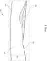
- Figure 2 illustrates blood vessels (e.g., arteries and veins) in the human body.
- blood vessels e.g., arteries and veins
- veins of the human body are labeled.
- aspects of the present disclosure can be related to peripheral vasculature, e.g., veins in the torso or legs.
- Occlusions can occur in arteries or veins.
- An occlusion can be generally representative of any blockage or other structural arrangement that results in a restriction to the flow of fluid through the lumen (e.g., an artery or a vein), for example, in a manner that is deleterious to the health of the patient.
- the occlusion narrows the lumen such that the cross-sectional area of the lumen and/or the available space for fluid to flow through the lumen is decreased.
- the occlusion may be a result of narrowing due to compression (e.g.
- the occlusion can be referenced as thrombus, a stenosis, and/or a lesion.
- the composition of the occlusion will depend on the type of anatomy being evaluated. Healthier portions of the anatomy may have a uniform or symmetrical profile (e.g., a cylindrical profile with a circular cross-sectional profile). The occlusion may not have a uniform or symmetrical profile. Accordingly, diseased or compressed portions of the anatomy, with the occlusion, will have a non-symmetric and/or otherwise irregular profile.
- the anatomy can have one occlusion or multiple occlusions.
- occlusion e.g., thrombus, deep vein thrombosis or DVT, chronic total occlusion or CTO, etc.
- the cross-sectional area of the vein in the peripheral vasculature e.g., torso, abdomen, groin, leg
- Other anatomy that contacts the vein can also reduce its cross-sectional area, thereby restricting blood flow therethrough.
- arteries or ligaments in the torso, abdomen, groin, or leg can press against a vein, which changes the shape of the vein and reduces its cross-sectional area.
- Such reductions in cross-sectional area resulting from contact with other anatomy can be referenced as compression, in that the walls of the vein are compressed as a result of the contact with the artery or ligament.
- Figure 3 illustrates a blood vessel 300 incorporating a compression 330.
- the compression 330 occurs outside the vessel walls 310 and may restrict the flow of blood 320.
- the compression may be caused by other anatomical structures outside the blood vessel 300, including but not limited to a tendon, ligament, or neighboring lumen.
- Figure 4 illustrates a blood vessel 300 incorporating a compression 330 and with a stent 440 expanded inside it to restore flow.
- the stent 440 displaces and arrests the compression 330, pushing the vessel walls 310 outward, thus reducing the flow restriction for the blood 320.
- Other treatment options for alleviating an occlusion may include but are not limited to thrombectomy, ablation, angioplasty, and pharmaceuticals. However, in a large majority of cases it may be highly desirable to obtain accurate and timely intravascular images of the affected area, along with accurate and detailed knowledge of the location, orientation, length, and volume of the affected area prior to, during, or after treatment.
- Figure 5 illustrates an example intraluminal imaging display screen 500 in accordance with at least one embodiment of the present disclosure.
- the screen display 500 includes a current tomographic IVUS image 510 from a series of successive tomographic images, an Image Longitudinal Display (ILD) 520 containing stacked longitudinal cross-sections of the series of successive tomographic images, and a graphical roadmap 530. Also visible are bookmarks 540a, 540b, 540c, 540d, 540e, and 540f, that are associated with both the graphical roadmap 530 and the ILD 520.
- Bookmark 540d is also associated with the current IVUS image 510, as is a label 550 that contains information about the location and nature of the IVUS image 510.
- the IVUS image is identified as a reference image of the left external iliac vein.
- the bookmark information can be saved to reports that are automatically generated. If a change to the bookmark is made in any of these locations, the automatic and assisted bookmarking system updates the bookmark in all of these locations, thus saving time and simplifying the bookmark editing workflow.
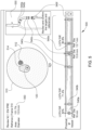
- Figure 6 shows a graphical roadmap screen display 530 of an exemplary automatic and assisted bookmarking system during a pullback procedure in a left leg vein of a patient, in accordance with at least one embodiment of the present disclosure.
- the graphical roadmap screen display includes multiple vein segments: the inferior vena cava (IVC) 610, the left common iliac vein (CIV) 620, the left external iliac vein (EIV) 630, left common femoral vein (CFV) 640, and a left femoral vein (F) 650.
- the corresponding segments on the right side 660 are also shown for reference, but are grayed out to indicate they are not part of the current procedure and will not be traversed by the intraluminal imaging probe during the procedure.
- the identification of vessel segments is performed automatically by the automatic and assisted bookmarking system (e.g., using image recognition, speed tracking, and position estimation), and bookmarks are automatically applied.
- bookmarks are predictively suggested to the clinician or other user. Predicting the next bookmark that the user will need advantageously avoids a requirement for the user to look through a list of bookmarks to find the correct one, or type in a manual bookmark.
- the identification of vessel segments is performed by a clinician or other user with the assistance of the automatic and assisted bookmarking system. Bookmarks or labels can be applied for example to a location where the segment begins or ends, or another segment begins or ends.
- the automatic and assisted bookmarking system is offering the clinician or other user an instruction 670 and a bookmark 680 that are based on the system's knowledge of the procedure being performed, the current location and movement direction of the intraluminal imaging probe 102 within the lumen 300, the proximity of anatomical landmarks (e.g., branches of the lumen or of neighboring lumens), and other information as necessary to perform the function.
- anatomical landmarks e.g., branches of the lumen or of neighboring lumens
- the clinician or other user When the clinician or other user has advanced the intraluminal imaging probe 102 into the portion of the lumen 300 indicated by the instruction 670, the clinician or other user then activates or confirms the bookmark, e.g., by double-clicking on it, or by dragging and dropping it onto the current intraluminal image 510 in the intraluminal imaging display screen 500, or by issuing a vocal command to confirm the bookmark for the current intraluminal image 510.
- the bookmark 680 is automatically associated not only with the current intraluminal image 510, but with the corresponding locations on the ILD 520 and graphical roadmap 530.
- the automatic and assisted bookmarking system automatically populates a label 550 that is automatically associated with the bookmark 680 and the current intraluminal image and may include, for example, the bookmark information, image location, and image type (e.g., reference, pre-treatment target, post-treatment target, etc.)
- these steps are performed automatically by the automatic and assisted bookmarking system, without the need for user input of any kind, based on image recognition to track known bifurcations of a vessel or lumen as anatomic landmarks. Bookmarks may also be suggested or automatically placed based on automated image recognition of issues such as thrombus, webbing, and compression (venous) or stenosis (arterial).
- border detection, image processing, image analysis, and/or pattern recognition examples include U.S. Pat. No. 6,200,268 entitled “VASCULAR PLAQUE CHARACTERIZATION” issued Mar. 13, 2001 with D. Geoffrey Vince, Barry D. Kuban and AnujaNair as inventors, U.S. Pat. No. 6,381,350 entitled “INTRAVASCULAR ULTRASONIC ANALYSIS USING ACTIVE CONTOUR METHOD AND SYSTEM” issued Apr. 30, 2002 with Jon D. Klingensmith, D. Geoffrey Vince and Raj Shekhar as inventors, U.S. Pat. No. 7,074,188 entitled “SYSTEM AND METHOD OF CHARACTERIZING VASCULAR TISSUE” issued Jul.
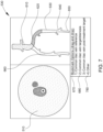
- Figure 7 shows a graphical roadmap screen display 530 of an exemplary automatic and assisted bookmarking system during a pullback procedure in a left leg vein of a patient, in accordance with at least one embodiment of the present disclosure.
- the graphical roadmap screen display includes multiple vein segments 610, 620, 630, 640, and 650. The corresponding segments on the right side 660 are also shown for reference, but are grayed out.
- the screen display also includes a tomographic image 510.
- the automatic and assisted bookmarking system offers a menu 670 that includes multiple different suggested markers (e.g., bookmarks) 680 that are based the system's knowledge of the procedure being undertaken and direction of probe movement, along with an approximate but imperfect knowledge of the location of the intraluminal imaging probe 102 within the lumen 300.
- the system also offers an "Other" option 780 that permits the clinician or other user to enter marker information (e.g., bookmark and label information) manually. This may be useful for example during nonstandard procedures, or during procedures where the positioning information for the intraluminal probe 102 is believed to be inaccurate.
- Inputs from the user allow the system to select a desired bookmark from among the suggested bookmarks 680 and 780.
- the bookmark can be dragged and dropped onto either the tomographic image 510 or the roadmap image 530, and it will automatically be applied to both at the location corresponding to the currently displayed tomographic image.
- a bookmark is a location marker on a pullback (e.g., on an ILD, roadmap, or cross-sectional tomographic image) that facilitates easy navigation.
- a label is a text annotation that can be associated with a region in a frame or a pullback, or even a bookmark.
- a bookmark can look like a little flag, or mark in a longitudinal view or roadmap.
- a label may comprise text that may or may not be associated with a bookmark.
- FIG. 8 is a flow diagram 800 for an intraluminal image bookmarking method according to the related art.
- a primary user e.g., a clinician
- the region of interest may for example be a target region where diseased or compressed tissue is to be inspected, or a reference region where the dimensions of the lumen 300 may be recorded for comparison purposes.
- step 820 the primary user calls for a bookmark to label the current intraluminal imaging frame.
- the primary user does not stop moving the intraluminal imaging probe 102, but continues pushing or pulling it at a near-constant speed.
- Step 830 represents an inevitable time delay between the primary user calling for a bookmark and a secondary user (e.g., a surgical assistant or non-sterile staff member) actually entering the bookmark information. This time delay is represented by the variable T1.
- the secondary user enters the bookmark information. This may involve typing in the current or suspected location of the intraluminal imaging probe 102, along with information about the type of image (e.g., target or reference). This data entry also takes time, represented by the variable T2. Meanwhile, in a typical intraluminal imaging procedure, the intraluminal imaging probe 102 continues moving at a relatively constant speed.
- the primary user reviews the intraluminal imaging data in a review mode of the intraluminal imaging system 100, and locates the bookmark 540 that was placed by the secondary user. Very frequently, because of time delays T1 and T2, the bookmark has been placed on a later frame than the intended frame. In some instances, the bookmark may be placed on an earlier than intended frame if the secondary user has anticipated and attempted to compensate for the time delays T1 and T2.
- step 860 the primary user pages through the intraluminal images 510 and/or the ILD 520 to find the image 510 where the bookmark 540 was intended to be placed.
- step 870 the primary user relocates the bookmark 540 to the desired image 510, or deletes and re-enters the bookmark 540.
- the primary user then performs measurements, annotations, and other analysis of the bookmarked image 510.
- Figure 9 is a is a flow diagram for an intraluminal image bookmarking method 900 according to at least one embodiment of the present disclosure.
- the primary user e.g., a clinician
- the region of interest may for example be a target region or a reference region.
- the automatic and assisted bookmarking method 900 suggests a bookmark 680 and/or associated label information 550 to the primary user.
- the system is able to anticipate what bookmarks will be needed, and in what order.
- the user may for example specify jugular entry or femoral entry, and the direction of movement (e.g., pullback or forward longitudinal movement).
- a typical procedure might for example involve pullback from either the abdomen to the leg or from the leg to the abdomen.
- the system knows the order and reverse order in which vessel segments occur (EIV, CIV, etc.) and presents them in the correct order based on the entry point and direction of movement.
- a user confirms the bookmark and/or associated label information.
- This confirmation may be performed for example by dragging and dropping the bookmark 680 onto the current intraluminal image 510, or by double-clicking on the bookmark 680, or by issuing a spoken confirmation to a voice recognition interface of the automatic and assisted bookmarking system (e.g., the processor circuit is receiving an electrical signal representative of the spoken confirmation).
- the bookmark 680 is placed directly onto the desired frame during the pullback procedure, and requires no rework during a review stage.
- step 940 the primary user continues moving the intraluminal imaging probe 102 at a constant speed through the lumen.
- the system may return to step 920 and suggest additional bookmarks during the procedure. In other instances, the process is complete after step 940.
- Another aspect of the automatic and assisted bookmarking system is to present the user with multiple neighboring frames around the bookmarked frame.
- the primary user doesn't usually get the bookmark placed at the right frame because of the time delay associated with T1 and perhaps T2.
- Some embodiments of the present disclosure assist the user by recording a set of frames or a short video clip around the bookmark that allows the user to have more confidence that the frame of interest is actually captured by the bookmark. The user can then select the actual frame during case review without accessing the main pullback itself for reporting or studying in the current case. Further, if the bookmark is edited in any of these frames, the change will be applied to all of them (and may also be applied to ILD or roadmap images), thus simplifying the bookmark editing workflow.
- FIG. 10 is a schematic diagram of a processor circuit 1050, according to embodiments of the present disclosure.
- the processor circuit 1050 may be implemented in the ultrasound imaging system 100, or other devices or workstations (e.g., third-party workstations, network routers, etc.), or on a cloud processor or other remote processing unit, as necessary to implement the method.
- the processor circuit 1050 may include a processor 1060, a memory 1064, and a communication module 1068. These elements may be in direct or indirect communication with each other, for example via one or more buses.
- the processor 1060 may include a central processing unit (CPU), a digital signal processor (DSP), an ASIC, a controller, or any combination of general-purpose computing devices, reduced instruction set computing (RISC) devices, application-specific integrated circuits (ASICs), field programmable gate arrays (FPGAs), or other related logic devices, including mechanical and quantum computers.
- the processor 1060 may also comprise another hardware device, a firmware device, or any combination thereof configured to perform the operations described herein.
- the processor 1060 may also be implemented as a combination of computing devices, e.g., a combination of a DSP and a microprocessor, a plurality of microprocessors, one or more microprocessors in conjunction with a DSP core, or any other such configuration.
- the memory 1064 may include a cache memory (e.g., a cache memory of the processor 1060), random access memory (RAM), magnetoresistive RAM (MRAM), read-only memory (ROM), programmable read-only memory (PROM), erasable programmable read only memory (EPROM), electrically erasable programmable read only memory (EEPROM), flash memory, solid state memory device, hard disk drives, other forms of volatile and non-volatile memory, or a combination of different types of memory.
- the memory 1064 includes a non-transitory computer-readable medium.
- the memory 1064 may store instructions 1066.
- the instructions 1066 may include instructions that, when executed by the processor 1060, cause the processor 1060 to perform the operations described herein.
- Instructions 1066 may also be referred to as code.
- the terms "instructions” and “code” should be interpreted broadly to include any type of computer-readable statement(s).
- the terms “instructions” and “code” may refer to one or more programs, routines, sub-routines, functions, procedures, etc.
- “Instructions” and “code” may include a single computer-readable statement or many computer-readable statements.
- the communication module 1068 can include any electronic circuitry and/or logic circuitry to facilitate direct or indirect communication of data between the processor circuit 1050, and other processors or devices.
- the communication module 1068 can be an input/output (I/O) device.
- the communication module 1068 facilitates direct or indirect communication between various elements of the processor circuit 1050 and/or the ultrasound imaging system 100.
- the communication module 1068 may communicate within the processor circuit 1050 through numerous methods or protocols.
- Serial communication protocols may include but are not limited to US SPI, I 2 C, RS-232, RS-485, CAN, Ethernet, ARINC 429, MODBUS, MIL-STD-1553, or any other suitable method or protocol.
- Parallel protocols include but are not limited to ISA, ATA, SCSI, PCI, IEEE-488, IEEE-1284, and other suitable protocols. Where appropriate, serial and parallel communications may be bridged by a UART, USART, or other appropriate subsystem.
- External communication may be accomplished using any suitable wireless or wired communication technology, such as a cable interface such as a USB, micro USB, Lightning, or FireWire interface, Bluetooth, Wi-Fi, ZigBee, Li-Fi, or cellular data connections such as 2G/GSM, 3G/UMTS, 4G/LTE/WiMax, or 5G.
- a Bluetooth Low Energy (BLE) radio can be used to establish connectivity with a cloud service, for transmission of data, and for receipt of software patches.
- the controller may be configured to communicate with a remote server, or a local device such as a laptop, tablet, or handheld device, or may include a display capable of showing status variables and other information. Information may also be transferred on physical media such as a USB flash drive or memory stick.
- FIG 11 is a screenshot of an IVUS access point selection screen 1100, in accordance with at least one embodiment of the present disclosure.
- the automatic and assisted bookmarking system may be generally capable of automatically identifying different regions of a patient's circulatory system by using a machine-learning algorithm or other training-based AI algorithm to match IVUS images against an a priori dataset or knowledge set of statistically representative lumen anatomy for different human subpopulations.
- the accuracy of vessel identification is improved when the IVUS pullback venogram system begins with accurate and specific information about the starting point and direction of travel of the ultrasound transducer 124 of the imaging catheter 102.
- the screen display 1100 therefore includes an access point selector 1110 that permits a clinician or other user to select between femoral access and jugular access.
- the screen display 1100 also includes a target limb selector 1120 that permits a clinician or other user to select between a patient's right leg and left leg as the location of the IVUS pullback.
- a target limb selector 1120 that permits a clinician or other user to select between a patient's right leg and left leg as the location of the IVUS pullback.
- target regions e.g., the abdomen
- target anatomy e.g., the heart
- exit button 1130 is also visible.
- Other controls may also be provided including but not limited to help buttons, procedure type selectors, disease type selectors, and anatomy type selectors.
- the automatic and assisted bookmarking system may be employed in anatomical systems within the body other than those described, or may be employed to image other disease types, object types, or procedure types than those described.
- the technology described herein may be applied to intraluminal imaging sensors of diverse types, whether currently in existence or hereinafter developed.
- the system may be employed with IVUS for coronary arterial and peripheral use in arterial or venous imaging, such as Philips' IGT-D devices and IVUS console software.
- the system may be employed with X-ray, angiogram, and venogram applications that require or enable labels and bookmarks.
- the system may be employed with any imaging modality that employs labels or bookmarks, but with allowed editing of those findings.
- connection references e.g., attached, coupled, connected, and joined are to be construed broadly and may include intermediate members between a collection of elements and relative movement between elements unless otherwise indicated. As such, connection references do not necessarily imply that two elements are directly connected and in fixed relation to each other.
- the term “or” shall be interpreted to mean “and/or” rather than “exclusive or.” Unless otherwise noted in the claims, stated values shall be interpreted as illustrative only and shall not be taken to be limiting.
Abstract
Description
- The subject matter described herein relates to a system for medical imaging. In particular, the disclosed system provides a system for bookmarking and labeling peripheral intravascular ultrasound or IVUS images during a pullback procedure. This system has particular but not exclusive utility for diagnosis and treatment of vascular diseases.
- Peripheral vascular procedures, such as angioplasty and stenting in peripheral venous (Inferior Vena Cava - IVC, iliac, femoral veins), IVC-filter retrieval, EVAR and FEVAR (and similar on the abdominal trait) atherectomy and thrombectomy are procedures where IVUS is used. Different diseases or medical procedures produce physical features with different size, structure, density, water content, and accessibility for imaging sensors. For example, a deep-vein thrombosis (DVT) produces a clot of blood cells, whereas post-thrombotic syndrome (PTS) produces webbing or other residual structural effects in a vessel that have similar composition to the vessel wall itself, and may thus be difficult to distinguish from the vessel wall. A stent is a dense (e.g., metallic) object that may be placed in a vessel or lumen to hold the vessel or lumen open to a particular diameter. A compression occurs when anatomical structures outside the vessel or lumen impinge on the vessel or lumen, constricting it.
- In some cases, intraluminal medical imaging is carried out with an IVUS device including one or more ultrasound transducers. The IVUS device may be passed into the vessel and guided to the area to be imaged. The transducers emit ultrasonic energy and receive ultrasound echoes reflected from the vessel. The ultrasound echoes are processed to create an image of the vessel of interest. The image of the vessel of interest may include one or more lesions or blockages in the vessel. A stent may be placed within the vessel to treat these blockages and intraluminal imaging may be carried out to view the placement of the stent within the vessel. Other types of treatment include thrombectomy, ablation, angioplasty, pharmaceuticals, etc.
- Labelling and annotations are often repetitive and time consuming in a typical IVUS workflow. Additionally, while placing bookmarks, the time between the physician or other user calling for bookmarks and actual placement of bookmark can lead to placement of the bookmark on a frame not originally intended by the physician or other user. In these cases, the physician or other user often has to go back and find the right frame of interest for further investigation, measurement, or analysis. Current methods of bookmarking/labelling often include selection from a pick list or editing that involves manual interaction by a user. Often, the saved bookmark includes only generic text that must later be customized or elaborated by the clinician.
- The information included in this Background section of the specification, including any references cited herein and any description or discussion thereof, is included for technical reference purposes only and is not to be regarded as subject matter by which the scope of the disclosure is to be bound.
- Disclosed is a system for advantageously tagging, labeling, and annotating intraluminal images from an intraluminal medical imaging sequence (e.g., an IVUS pullback sequence) using labels automatically (e.g., predictively) provided by the system, or else selected by a user from a short list automatically provided by the system, thus permitting rapid, accurate real-time bookmarking of the location and severity of diseases or compressions of the lumen, along with reference images, post-treatment images, and other images. The system is hereinafter referred to as an automatic and assisted bookmarking system.
- Automatically generated or assistive-ly suggested labels/bookmarks for IVUS make the placement of labels/bookmarks simpler and faster than is currently possible. By having the user select a procedure type such as coronary/peripheral, venous or arterial, the system is able to supply a list of relevant bookmarks for the user to select. The user can drag and drop the labels/bookmarks where appropriate, and can also edit labels and bookmarks as needed. Labels and bookmarks can be automated, semi-automated or user driven. Bookmarks can also provide a selectable range of neighboring frames to choose from.
- The automatic and assisted bookmarking system disclosed herein has particular, but not exclusive, utility for intraluminal ultrasound imaging procedures. One general aspect includes an intraluminal ultrasound imaging system, including: a processor circuit configured for communication with an intraluminal ultrasound imaging catheter, where the processor circuit is configured to: receive a plurality of intraluminal ultrasound images obtained by the intraluminal ultrasound imaging catheter during movement of the intraluminal ultrasound imaging catheter within a body lumen of a patient, the body lumen including a plurality of segments; generate a marker to be applied to an intraluminal ultrasound image of the plurality of intraluminal ultrasound images, where the marker is generated based on the movement of the intraluminal ultrasound imaging catheter, and where the marker is predictive and/or representative of a segment of the plurality of segments; and output, to a display in communication with the processor circuit, a screen display including the marker and the plurality of intraluminal ultrasound images. Other embodiments of this aspect include corresponding computer systems, apparatus, and computer programs recorded on one or more computer storage devices, each configured to perform the actions of the methods.
- Implementations may include one or more of the following features. The system further including a user interface, where the processor circuit is configured to receive a user input, via the user interface, to apply the marker to the intraluminal ultrasound image of the plurality of intraluminal ultrasound images. The system where, in response to the receiving the user input to apply the marker, the processor circuit is configured to apply with the marker one or more other intraluminal ultrasound images neighboring the intraluminal ultrasound image. The system where the display includes a touchscreen, and where the user interface includes a drag-and-drop interface on the touchscreen, and where the user input includes a drag-and-drop input. The system where the user interface includes a voice recognition interface, and the user input includes a spoken confirmation. The system where the processor circuit is further configured to output stylized diagram of the body lumen including the plurality of segments, where the marker identifies a location in the stylized diagram where the segment begins. The system where the processor circuit is configured to: generate a plurality of markers to be applied to the plurality of ultrasound images; and output the plurality of markers successively, where each of the plurality of markers corresponds to a different segment of the plurality of segments. The system where the processor circuit is configured to determine an order for the successive output of the plurality of markers based on the movement of the intraluminal ultrasound imaging catheter. The system where the processor circuit is configured to determine the order based on at least one of an access point to the body lumen or a direction of movement of the intraluminal ultrasound imaging catheter. The system further including the intraluminal ultrasound imaging catheter, where the intraluminal ultrasound imaging catheter includes an intravascular ultrasound (IVUS) imaging catheter, and where the body lumen includes a peripheral blood vessel. Implementations of the described techniques may include hardware, a method or process, or computer software on a computer-accessible medium.
- One general aspect includes an intraluminal ultrasound imaging system, including: a processor circuit configured for communication with an intraluminal ultrasound imaging catheter, where the processor circuit is configured to: receive an intraluminal ultrasound image obtained by the intraluminal ultrasound imaging catheter during movement of the intraluminal ultrasound imaging catheter within a body lumen of a patient; generate a plurality of text labels; output a screen display including a first portion includes the intraluminal ultrasound image and a second portion including the plurality of text labels, where the first portion is proximate to the second portion; receive a drag-and-drop user input moving a text label of the plurality of text labels from the second portion to the first portion; and associate the text label with the intraluminal ultrasound image. Other embodiments of this aspect include corresponding computer systems, apparatus, and computer programs recorded on one or more computer storage devices, each configured to perform the actions of the methods.
- One general aspect includes an intraluminal ultrasound imaging method, including: receiving, at a processor circuit in communication with an intraluminal ultrasound imaging catheter, a plurality intraluminal ultrasound images obtained by the intraluminal ultrasound imaging catheter during movement of the intraluminal ultrasound imaging catheter within a body lumen of a patient, the body lumen including a plurality of segments; generating a marker to be applied to an intraluminal ultrasound image of the plurality intraluminal ultrasound images, where the marker is generated based on the movement of the intraluminal ultrasound imaging catheter, and where the marker is predictive and/or representative of a segment of the plurality of segments; and outputting, to a display in communication with the processor circuit, a screen display including the marker and the plurality of intraluminal ultrasound images shown successively. Other embodiments of this aspect include corresponding computer systems, apparatus, and computer programs recorded on one or more computer storage devices, each configured to perform the actions of the methods.
- Implementations may include one or more of the following features. The method further including receiving a user input, via a user interface operating on the processor circuit, to apply the marker to the intraluminal ultrasound image of the plurality of intraluminal ultrasound images. The method further including, in response to the receiving the user input to apply the marker, applying the marker to one or more other intraluminal ultrasound images neighboring the intraluminal ultrasound image. The method where the display includes a touchscreen, and where the user interface includes a drag-and-drop interface on the touchscreen, and where the user input includes a drag-and-drop input. The method where the user interface includes a voice recognition interface, and the user input includes a spoken confirmation. The method further including outputting a stylized diagram of the body lumen including the plurality of segments, where the marker identifies a location in the stylized diagram where the segment begins. The method further including: generating a plurality of markers to be applied to the plurality of ultrasound images; and outputting, to the display in communication with the processor circuit, a screen display including the plurality of markers successively, where each of the plurality of markers corresponds to a different segment of the plurality of segments. The method further including determining an order for the successive output of the plurality of markers based on the movement of the intraluminal ultrasound imaging catheter. The method further including determining the order based on at least one of an access point to the body lumen or a direction of movement of the intraluminal ultrasound imaging catheter. Implementations of the described techniques may include hardware, a method or process, or computer software on a computer-accessible medium.
- This Summary is provided to introduce a selection of concepts in a simplified form that are further described below in the Detailed Description. This Summary is not intended to identify key features or essential features of the claimed subject matter, nor is it intended to limit the scope of the claimed subject matter. A more extensive presentation of features, details, utilities, and advantages of the automatic and assisted bookmarking system, as defined in the claims, is provided in the following written description of various embodiments of the disclosure and illustrated in the accompanying drawings.
- Illustrative embodiments of the present disclosure will be described with reference to the accompanying drawings, of which:
-
Figure 1 is a diagrammatic schematic view of an intraluminal imaging system, according to aspects of the present disclosure. -
Figure 2 illustrates blood vessels (e.g., arteries and veins) in the human body. -
Figure 3 illustrates a blood vessel incorporating a compression. -
Figure 4 illustrates a blood vessel incorporating a compression and with a stent expanded inside it to restore flow. -
Figure 5 illustrates an example intraluminal imaging display screen in accordance with at least one embodiment of the present disclosure. -
Figure 6 shows a graphical roadmap screen display of an exemplary automatic and assisted bookmarking system during a pullback procedure in a left leg vein of a patient, in accordance with at least one embodiment of the present disclosure. -
Figure 7 shows a graphical roadmap screen display of an exemplary automatic and assisted bookmarking system during a pullback procedure in a left leg vein of a patient, in accordance with at least one embodiment of the present disclosure. -
Figure 8 is a flow diagram for an intraluminal image bookmarking method according to the related art. -
Figure 9 is a flow diagram for an intraluminal image bookmarking method according to at least one embodiment of the present disclosure. -
Figure 10 is a schematic diagram of a processor circuit, according to embodiments of the present disclosure. -
Figure 11 is a screenshot of an IVUS access point selection screen, in accordance with at least one embodiment of the present disclosure. - The present disclosure relates generally to medical imaging, including imaging associated with a body lumen of a patient using an intraluminal imaging device. For example, the present disclosure describes systems, devices, and methods for labeling and bookmarking intraluminal images during an intraluminal imaging procedure such as an IVUS pullback. Drag and drop labels and bookmarks are provided to users to enable a simpler and faster way of placing labels and bookmarks. Appropriate labels and bookmarks appear based on user selections including procedure type (coronary/peripheral, venous/arterial, etc.), entry point, entry direction or pullback direction, and disease type. Labels and bookmarks contain information such as anatomical references or disease states/types. Using confirmation inputs from the user, the system is able to place the labels and bookmarkers where and when appropriate. The system also makes it possible to customize or edit labels and bookmarks. Labels and bookmarks can be saved to the IVUS image, ILD, graphical representation of anatomy, pre/post images, roadmap images, and reports. On the anatomical map, automated labels would appear in successive order to allow users to correctly label anatomical segments, as well as segments or sub-segments within the segments (e.g., a lesion/plaque buildup, an area of compression, healthy tissue used as a reference, etc.). The creation of labels or bookmarks can be automated, semi-automated or user driven, according to aspects of the present disclosure.
- The automatic and/or assisted bookmarking system provides easy and fast placement of labels and bookmarks using (for example) drag and drop functionality, not only to the IVUS image itself but to an ILD, graphical roadmap or other graphical representation of anatomy, for both pre- and post-treatment images. In an example, the processor circuit is receiving an electrical signal representative of the drag and drop input. Depending on the application, a list of commonly used labels for anatomical locations/ disease states is created for coronary/peripheral and venous/arterial procedures, and accessed by the user via drag and drop functionality. Additionally, a user of the system is able to manually edit labels and/or bookmarks as desired, if necessary. This system is hereinafter referred to as an automatic and assisted bookmarking system.
- The devices, systems, and methods described herein can include one or more features described in
U.S. Provisional App. No. 62/750,983, filed 26 October 2018 U.S. Provisional App. No. 62/751,268, filed 26 October 2018 U.S. Provisional App. No. 62/751,289, filed 26 October 2018 U.S. Provisional App. No. 62/750,996, filed 26 October 2018 U.S. Provisional App. No. 62/751,167, filed 26 October 2018 U.S. Provisional App. No. 62/751,185, filed 26 October 2018 - The devices, systems, and methods described herein can also include one or more features described in
U.S. Provisional App. No. 62/642,847, filed March 14, 2018 March 12, 2019 as US Serial No. 16/351175 U.S. Provisional App. No. 62/712,009, filed July 30, 2018 U.S. Provisional App. No. 62/711,927, filed July 30, 2018 U.S. Provisional App. No. 62/643,366, filed March 15, 2018 March 15, 2019 as US Serial No. 16/354970 - The present disclosure substantially aids a clinician in making sense of large volumes of intraluminal imaging data, along with reporting and treatment planning, plus reduced case time and improved ease of use. The present disclosure accomplishes this by providing a quick, seamless process for identification, marking, and annotation of locations of interest within a vessel or lumen along an examined length, in real time during the imaging procedure (e.g., an IVUS pullback procedure). Implemented on a medical imaging console (e.g., an IVUS imaging console) in communication with a medical imaging sensor (e.g., an intraluminal ultrasound sensor), the automatic and assisted bookmarking system disclosed herein provides both time savings and an improvement in the accuracy of bookmarking and labeling of captured images. This improved imaging workflow transforms a time-consuming process of imaging, image selection, data entry, review, and revision into a streamlined process involving both fewer steps and simpler steps. This occurs for example without the normally routine need for secondary or non-sterile users to type in bookmark and label data in real time, along with the associated time lags. This unconventional approach improves the functioning of the medical imaging console and sensor, by automating bookmarking and labeling steps that are normally performed manually by the clinician or other users.
- The automatic and assisted bookmarking system may be implemented as a set of logical branches and mathematical operations, whose outputs are viewable on a display, and operated by a control process executing on a processor that accepts user inputs (e.g., from a user interface such as a keyboard, mouse, or touchscreen interface), and that is in communication with one or more medical imaging sensors (e.g., intraluminal ultrasound sensors). In that regard, the control process performs certain specific operations in response to different inputs or selections made by a user at the start of an imaging procedure, and may also respond to inputs made by the user during the procedure. Certain structures, functions, and operations of the processor, display, sensors, and user input systems are known in the art, while others are recited herein to enable novel features or aspects of the present disclosure with particularity.
- Various types of intraluminal imaging systems are used in diagnosing and treating diseases. For example, intravascular ultrasound (IVUS) imaging is used as a diagnostic tool for visualizing vessels within a body of a patient. This may aid in assessing diseased or compressed vessels, such as arteries or veins, within the human body to determine the need for treatment, to optimize treatment, and/or to assess a treatment's effectiveness (e.g., through imaging of the vessel before and after treatment).
- In some cases, intraluminal imaging is carried out with an IVUS device including one or more ultrasound transducers. The IVUS device may be passed into the vessel and guided to the area to be imaged. The transducers emit ultrasonic energy and receive ultrasound echoes reflected from the vessel. The ultrasound echoes are processed to create an image of the vessel of interest. The image of the vessel of interest may include one or more lesions or blockages in the vessel. A stent may be placed within the vessel to treat these blockages and intraluminal imaging may be carried out to view the placement of the stent within the vessel. Other types of treatment include thrombectomy, ablation, angioplasty, pharmaceuticals, etc.
- In some embodiments, the automatic and assisted bookmarking system includes screen displays that provide a clinician with a suggested "next bookmark" representing an upcoming region of interest, along with associated label information, that the clinician or another user can simply confirm when the desired intraluminal imaging frame from within the region of interest appears on the display.
- When recording an IVUS pullback, the IVUS system successively stacks a cross-section of each recorded tomographic frame onscreen. The resulting image stack is called the In Line Digital or Image Longitudinal Display (ILD) view. Bookmarks can be automatically associated with the intraluminal image itself, as well as the ILD and/or a roadmap or graphical roadmap image, and reports generated therefrom.
- IVUS pullback measurements results require recording, bookmarking, labeling, annotation, and reporting on the part of the clinician. The automatic and assisted bookmarking system eases the workload on the clinician, and permits certain aspects of bookmarking, labeling annotation and reporting to happen automatically during the IVUS procedure itself.
- These descriptions are provided for exemplary purposes only, and should not be considered to limit the scope of the automatic and assisted bookmarking system. Certain features may be added, removed, or modified without departing from the spirit of the claimed subject matter.
- For the purposes of promoting an understanding of the principles of the present disclosure, reference will now be made to the embodiments illustrated in the drawings, and specific language will be used to describe the same. It is nevertheless understood that no limitation to the scope of the disclosure is intended. Any alterations and further modifications to the described devices, systems, and methods, and any further application of the principles of the present disclosure are fully contemplated and included within the present disclosure as would normally occur to one skilled in the art to which the disclosure relates. In particular, it is fully contemplated that the features, components, and/or steps described with respect to one embodiment may be combined with the features, components, and/or steps described with respect to other embodiments of the present disclosure. For the sake of brevity, however, the numerous iterations of these combinations will not be described separately.
-
Figure 1 is a diagrammatic schematic view of an intraluminal imaging system incorporating the automatic and assisted bookmarking system, according to aspects of the present disclosure. Theintraluminal imaging system 100 can be an intravascular ultrasound (IVUS) imaging system in some embodiments. Theintraluminal imaging system 100 may include anintraluminal device 102, a patient interface module (PIM) 104, a console orprocessing system 106, amonitor 108, and anexternal imaging system 132 which may include angiography, ultrasound, X-ray, computed tomography (CT), magnetic resonance imaging (MRI), or other imaging technologies, equipment, and methods. Theintraluminal device 102 is sized and shaped, and/or otherwise structurally arranged to be positioned within a body lumen of a patient. For example, theintraluminal device 102 can be a catheter, guide wire, guide catheter, pressure wire, and/or flow wire in various embodiments. In some circumstances, thesystem 100 may include additional elements and/or may be implemented without one or more of the elements illustrated inFigure 1 . For example, thesystem 100 may omit theexternal imaging system 132. - The intraluminal imaging system 100 (or intravascular imaging system) can be any type of imaging system suitable for use in the lumens or vasculature of a patient. In some embodiments, the
intraluminal imaging system 100 is an intraluminal ultrasound (IVUS) imaging system. In other embodiments, theintraluminal imaging system 100 may include systems configured for forward looking intraluminal ultrasound (FL-IVUS) imaging, intraluminal photoacoustic (IVPA) imaging, intracardiac echocardiography (ICE), transesophageal echocardiography (TEE), and/or other suitable imaging modalities. - It is understood that the
system 100 and/ordevice 102 can be configured to obtain any suitable intraluminal imaging data. In some embodiments, thedevice 102 may include an imaging component of any suitable imaging modality, such as optical imaging, optical coherence tomography (OCT), etc. In some embodiments, thedevice 102 may include any suitable non-imaging component, including a pressure sensor, a flow sensor, a temperature sensor, an optical fiber, a reflector, a mirror, a prism, an ablation element, a radio frequency (RF) electrode, a conductor, or combinations thereof. Generally, thedevice 102 can include an imaging element to obtain intraluminal imaging data associated with thelumen 120. Thedevice 102 may be sized and shaped (and/or configured) for insertion into a vessel orlumen 120 of the patient. - The
system 100 may be deployed in a catheterization laboratory having a control room. Theprocessing system 106 may be located in the control room. Optionally, theprocessing system 106 may be located elsewhere, such as in the catheterization laboratory itself. The catheterization laboratory may include a sterile field while its associated control room may or may not be sterile depending on the procedure to be performed and/or on the health care facility. The catheterization laboratory and control room may be used to perform any number of medical imaging procedures such as angiography, fluoroscopy, CT, IVUS, virtual histology (VH), forward looking IVUS (FL-IVUS), intraluminal photoacoustic (IVPA) imaging, a fractional flow reserve (FFR) determination, a coronary flow reserve (CFR) determination, optical coherence tomography (OCT), computed tomography, intracardiac echocardiography (ICE), forward-looking ICE (FLICE), intraluminal palpography, transesophageal ultrasound, fluoroscopy, and other medical imaging modalities, or combinations thereof. In some embodiments,device 102 may be controlled from a remote location such as the control room, such than an operator is not required to be in close proximity to the patient. - The
intraluminal device 102,PIM 104, monitor 108, andexternal imaging system 132 may be communicatively coupled directly or indirectly to theprocessing system 106. These elements may be communicatively coupled to themedical processing system 106 via a wired connection such as a standard copper link or a fiber optic link and/or via wireless connections using IEEE 802.11 Wi-Fi standards, Ultra Wide-Band (UWB) standards, wireless FireWire, wireless USB, or another high-speed wireless networking standard. Theprocessing system 106 may be communicatively coupled to one or more data networks, e.g., a TCP/IP-based local area network (LAN). In other embodiments, different protocols may be utilized such as Synchronous Optical Networking (SONET). In some cases, theprocessing system 106 may be communicatively coupled to a wide area network (WAN). Theprocessing system 106 may utilize network connectivity to access various resources. For example, theprocessing system 106 may communicate with a Digital Imaging and Communications in Medicine (DICOM) system, a Picture Archiving and Communication System (PACS), and/or a Hospital Information System (HIS) via a network connection. - At a high level, an ultrasound imaging
intraluminal device 102 emits ultrasonic energy from atransducer array 124 included inscanner assembly 110 mounted near a distal end of theintraluminal device 102. The ultrasonic energy is reflected by tissue structures in the medium (such as a lumen 120) surrounding thescanner assembly 110, and the ultrasound echo signals are received by thetransducer array 124. Thescanner assembly 110 generates electrical signal(s) representative of the ultrasound echoes. Thescanner assembly 110 can include one or more single ultrasound transducers and/or atransducer array 124 in any suitable configuration, such as a planar array, a curved array, a circumferential array, an annular array, etc. For example, thescanner assembly 110 can be a one-dimensional array or a two-dimensional array in some instances. In some instances, thescanner assembly 110 can be a rotational ultrasound device. The active area of thescanner assembly 110 can include one or more transducer materials and/or one or more segments of ultrasound elements (e.g., one or more rows, one or more columns, and/or one or more orientations) that can be uniformly or independently controlled and activated. The active area of thescanner assembly 110 can be patterned or structured in various basic or complex geometries. Thescanner assembly 110 can be disposed in a side-looking orientation (e.g., ultrasonic energy emitted perpendicular and/or orthogonal to the longitudinal axis of the intraluminal device 102) and/or a forward-looking looking orientation (e.g., ultrasonic energy emitted parallel to and/or along the longitudinal axis). In some instances, thescanner assembly 110 is structurally arranged to emit and/or receive ultrasonic energy at an oblique angle relative to the longitudinal axis, in a proximal or distal direction. In some embodiments, ultrasonic energy emission can be electronically steered by selective triggering of one or more transducer elements of thescanner assembly 110. - The ultrasound transducer(s) of the
scanner assembly 110 can be a piezoelectric micromachined ultrasound transducer (PMUT), capacitive micromachined ultrasonic transducer (CMUT), single crystal, lead zirconate titanate (PZT), PZT composite, other suitable transducer type, and/or combinations thereof. In an embodiment theultrasound transducer array 124 can include any suitable number of individual transducer elements or acoustic elements between 1 acoustic element and 1000 acoustic elements, including values such as 2 acoustic elements, 4 acoustic elements, 36 acoustic elements, 64 acoustic elements, 128 acoustic elements, 500 acoustic elements, 812 acoustic elements, and/or other values both larger and smaller. - The
PIM 104 transfers the received echo signals to theprocessing system 106 where the ultrasound image (including the flow information) is reconstructed and displayed on themonitor 108. The console orprocessing system 106 can include a processor and a memory. Theprocessing system 106 may be operable to facilitate the features of theintraluminal imaging system 100 described herein. For example, the processor can execute computer readable instructions stored on the non-transitory tangible computer readable medium. - The
PIM 104 facilitates communication of signals between theprocessing system 106 and thescanner assembly 110 included in theintraluminal device 102. This communication may include providing commands to integrated circuit controller chip(s) within theintraluminal device 102, selecting particular element(s) on thetransducer array 124 to be used for transmit and receive, providing the transmit trigger signals to the integrated circuit controller chip(s) to activate the transmitter circuitry to generate an electrical pulse to excite the selected transducer array element(s), and/or accepting amplified echo signals received from the selected transducer array element(s) via amplifiers included on the integrated circuit controller chip(s). In some embodiments, thePIM 104 performs preliminary processing of the echo data prior to relaying the data to theprocessing system 106. In examples of such embodiments, thePIM 104 performs amplification, filtering, and/or aggregating of the data. In an embodiment, thePIM 104 also supplies high- and low-voltage DC power to support operation of theintraluminal device 102 including circuitry within thescanner assembly 110. - The
processing system 106 receives echo data from thescanner assembly 110 by way of thePIM 104 and processes the data to reconstruct an image of the tissue structures in the medium surrounding thescanner assembly 110. Generally, thedevice 102 can be utilized within any suitable anatomy and/or body lumen of the patient. Theprocessing system 106 outputs image data such that an image of the vessel orlumen 120, such as a cross-sectional IVUS image of thelumen 120, is displayed on themonitor 108.Lumen 120 may represent fluid filled or fluid-surrounded structures, both natural and man-made.Lumen 120 may be within a body of a patient.Lumen 120 may be a blood vessel, such as an artery or a vein of a patient's vascular system, including cardiac vasculature, peripheral vasculature, neural vasculature, renal vasculature, and/or or any other suitable lumen inside the body. For example, thedevice 102 may be used to examine any number of anatomical locations and tissue types, including without limitation, organs including the liver, heart, kidneys, gall bladder, pancreas, lungs; ducts; intestines; nervous system structures including the brain, dural sac, spinal cord and peripheral nerves; the urinary tract; as well as valves within the blood, chambers or other parts of the heart, and/or other systems of the body. In addition to natural structures, thedevice 102 may be used to examine man-made structures such as, but without limitation, heart valves, stents, shunts, filters and other devices. - The controller or
processing system 106 may include a processing circuit having one or more processors in communication with memory and/or other suitable tangible computer readable storage media. The controller orprocessing system 106 may be configured to carry out one or more aspects of the present disclosure. In some embodiments, theprocessing system 106 and themonitor 108 are separate components. In other embodiments, theprocessing system 106 and themonitor 108 are integrated in a single component. For example, thesystem 100 can include a touch screen device, including a housing having a touch screen display and a processor. Thesystem 100 can include any suitable input device, such as a touch sensitive pad or touch screen display, keyboard/mouse, joystick, button, etc., for a user to select options shown on themonitor 108. Theprocessing system 106, themonitor 108, the input device, and/or combinations thereof can be referenced as a controller of thesystem 100. The controller can be in communication with thedevice 102, thePIM 104, theprocessing system 106, themonitor 108, the input device, and/or other components of thesystem 100. - In some embodiments, the
intraluminal device 102 includes some features similar to traditional solid-state IVUS catheters, such as the EagleEye® catheter available from Volcano Corporation and those disclosed inU.S. Patent No. 7,846,101 hereby incorporated by reference in its entirety. For example, theintraluminal device 102 may include thescanner assembly 110 near a distal end of theintraluminal device 102 and atransmission line bundle 112 extending along the longitudinal body of theintraluminal device 102. The cable ortransmission line bundle 112 can include a plurality of conductors, including one, two, three, four, five, six, seven, or more conductors. - The
transmission line bundle 112 terminates in aPIM connector 114 at a proximal end of theintraluminal device 102. ThePIM connector 114 electrically couples thetransmission line bundle 112 to thePIM 104 and physically couples theintraluminal device 102 to thePIM 104. In an embodiment, theintraluminal device 102 further includes aguidewire exit port 116. Accordingly, in some instances theintraluminal device 102 is a rapid-exchange catheter. Theguidewire exit port 116 allows aguidewire 118 to be inserted towards the distal end in order to direct theintraluminal device 102 through thelumen 120. - The
monitor 108 may be a display device such as a computer monitor or other type of screen. Themonitor 108 may be used to display selectable prompts, instructions, and visualizations of imaging data to a user. In some embodiments, themonitor 108 may be used to provide a procedure-specific workflow to a user to complete an intraluminal imaging procedure. This workflow may include performing a pre-stent plan to determine the state of a lumen and potential for a stent, as well as a post-stent inspection to determine the status of a stent that has been positioned in a lumen. The workflow may be presented to a user as any of the displays or visualizations shown inFigs. 5-11 . - The
external imaging system 132 can be configured to obtain x-ray, radiographic, angiographic/venographic (e.g., with contrast), and/or fluoroscopic (e.g., without contrast) images of the body of a patient (including the vessel 120).External imaging system 132 may also be configured to obtain computed tomography images of the body of the patient (including the vessel 120). Theexternal imaging system 132 may include an external ultrasound probe configured to obtain ultrasound images of the body of the patient (including the vessel 120) while positioned outside the body. In some embodiments, thesystem 100 includes other imaging modality systems (e.g., MRI) to obtain images of the body of the patient (including the vessel 120). Theprocessing system 106 can utilize the images of the body of the patient in conjunction with the intraluminal images obtained by theintraluminal device 102. -
Figure 2 illustrates blood vessels (e.g., arteries and veins) in the human body. For example, veins of the human body are labeled. Aspects of the present disclosure can be related to peripheral vasculature, e.g., veins in the torso or legs. - Occlusions can occur in arteries or veins. An occlusion can be generally representative of any blockage or other structural arrangement that results in a restriction to the flow of fluid through the lumen (e.g., an artery or a vein), for example, in a manner that is deleterious to the health of the patient. For example, the occlusion narrows the lumen such that the cross-sectional area of the lumen and/or the available space for fluid to flow through the lumen is decreased. Where the anatomy is a blood vessel, the occlusion may be a result of narrowing due to compression (e.g. from external vessels), plaque buildup, including without limitation plaque components such as fibrous, fibro-lipidic (fibro fatty), necrotic core, calcified (dense calcium), blood, and/or different stages of thrombus (e.g., acute, sub-acute, chronic, etc.). In some instances, the occlusion can be referenced as thrombus, a stenosis, and/or a lesion. Generally, the composition of the occlusion will depend on the type of anatomy being evaluated. Healthier portions of the anatomy may have a uniform or symmetrical profile (e.g., a cylindrical profile with a circular cross-sectional profile). The occlusion may not have a uniform or symmetrical profile. Accordingly, diseased or compressed portions of the anatomy, with the occlusion, will have a non-symmetric and/or otherwise irregular profile. The anatomy can have one occlusion or multiple occlusions.
- Build-up of occlusion (e.g., thrombus, deep vein thrombosis or DVT, chronic total occlusion or CTO, etc.) is one way in which the cross-sectional area of the vein in the peripheral vasculature (e.g., torso, abdomen, groin, leg) may be reduced. Other anatomy that contacts the vein can also reduce its cross-sectional area, thereby restricting blood flow therethrough. For example, arteries or ligaments in the torso, abdomen, groin, or leg can press against a vein, which changes the shape of the vein and reduces its cross-sectional area. Such reductions in cross-sectional area resulting from contact with other anatomy can be referenced as compression, in that the walls of the vein are compressed as a result of the contact with the artery or ligament.
-
Figure 3 illustrates ablood vessel 300 incorporating acompression 330. Thecompression 330 occurs outside thevessel walls 310 and may restrict the flow ofblood 320. The compression may be caused by other anatomical structures outside theblood vessel 300, including but not limited to a tendon, ligament, or neighboring lumen. -
Figure 4 illustrates ablood vessel 300 incorporating acompression 330 and with astent 440 expanded inside it to restore flow. Thestent 440 displaces and arrests thecompression 330, pushing thevessel walls 310 outward, thus reducing the flow restriction for theblood 320. Other treatment options for alleviating an occlusion may include but are not limited to thrombectomy, ablation, angioplasty, and pharmaceuticals. However, in a large majority of cases it may be highly desirable to obtain accurate and timely intravascular images of the affected area, along with accurate and detailed knowledge of the location, orientation, length, and volume of the affected area prior to, during, or after treatment. -
Figure 5 illustrates an example intraluminalimaging display screen 500 in accordance with at least one embodiment of the present disclosure. In this example, thescreen display 500 includes a currenttomographic IVUS image 510 from a series of successive tomographic images, an Image Longitudinal Display (ILD) 520 containing stacked longitudinal cross-sections of the series of successive tomographic images, and agraphical roadmap 530. Also visible arebookmarks graphical roadmap 530 and theILD 520.Bookmark 540d is also associated with thecurrent IVUS image 510, as is alabel 550 that contains information about the location and nature of theIVUS image 510. In this example, the IVUS image is identified as a reference image of the left external iliac vein. In addition, the bookmark information can be saved to reports that are automatically generated. If a change to the bookmark is made in any of these locations, the automatic and assisted bookmarking system updates the bookmark in all of these locations, thus saving time and simplifying the bookmark editing workflow. -
Figure 6 shows a graphicalroadmap screen display 530 of an exemplary automatic and assisted bookmarking system during a pullback procedure in a left leg vein of a patient, in accordance with at least one embodiment of the present disclosure. In this example, the graphical roadmap screen display includes multiple vein segments: the inferior vena cava (IVC) 610, the left common iliac vein (CIV) 620, the left external iliac vein (EIV) 630, left common femoral vein (CFV) 640, and a left femoral vein (F) 650. The corresponding segments on theright side 660 are also shown for reference, but are grayed out to indicate they are not part of the current procedure and will not be traversed by the intraluminal imaging probe during the procedure. Other vessel segments or lumen segments may be identified in other areas of the body. In some embodiments, the identification of vessel segments is performed automatically by the automatic and assisted bookmarking system (e.g., using image recognition, speed tracking, and position estimation), and bookmarks are automatically applied. In other embodiments, bookmarks are predictively suggested to the clinician or other user. Predicting the next bookmark that the user will need advantageously avoids a requirement for the user to look through a list of bookmarks to find the correct one, or type in a manual bookmark. In other embodiments, the identification of vessel segments is performed by a clinician or other user with the assistance of the automatic and assisted bookmarking system. Bookmarks or labels can be applied for example to a location where the segment begins or ends, or another segment begins or ends. - In the example shown in
Figure 6 , the automatic and assisted bookmarking system is offering the clinician or other user aninstruction 670 and abookmark 680 that are based on the system's knowledge of the procedure being performed, the current location and movement direction of theintraluminal imaging probe 102 within thelumen 300, the proximity of anatomical landmarks (e.g., branches of the lumen or of neighboring lumens), and other information as necessary to perform the function. When the clinician or other user has advanced theintraluminal imaging probe 102 into the portion of thelumen 300 indicated by theinstruction 670, the clinician or other user then activates or confirms the bookmark, e.g., by double-clicking on it, or by dragging and dropping it onto the currentintraluminal image 510 in the intraluminalimaging display screen 500, or by issuing a vocal command to confirm the bookmark for the currentintraluminal image 510. When this is done, thebookmark 680 is automatically associated not only with the currentintraluminal image 510, but with the corresponding locations on theILD 520 andgraphical roadmap 530. In addition, the automatic and assisted bookmarking system automatically populates alabel 550 that is automatically associated with thebookmark 680 and the current intraluminal image and may include, for example, the bookmark information, image location, and image type (e.g., reference, pre-treatment target, post-treatment target, etc.) In some embodiments, these steps are performed automatically by the automatic and assisted bookmarking system, without the need for user input of any kind, based on image recognition to track known bifurcations of a vessel or lumen as anatomic landmarks. Bookmarks may also be suggested or automatically placed based on automated image recognition of issues such as thrombus, webbing, and compression (venous) or stenosis (arterial). - Examples of border detection, image processing, image analysis, and/or pattern recognition include
U.S. Pat. No. 6,200,268 entitled "VASCULAR PLAQUE CHARACTERIZATION" issued Mar. 13, 2001 with D. Geoffrey Vince, Barry D. Kuban and AnujaNair as inventors,U.S. Pat. No. 6,381,350 entitled "INTRAVASCULAR ULTRASONIC ANALYSIS USING ACTIVE CONTOUR METHOD AND SYSTEM" issued Apr. 30, 2002 with Jon D. Klingensmith, D. Geoffrey Vince and Raj Shekhar as inventors,U.S. Pat. No. 7,074,188 entitled "SYSTEM AND METHOD OF CHARACTERIZING VASCULAR TISSUE" issued Jul. 11, 2006 with Anuja Nair, D. Geoffrey Vince, Jon D. Klingensmith and Barry D. Kuban as inventors,U.S. Pat. No. 7,175,597 entitled "NON-INVASIVE TISSUE CHARACTERIZATION SYSTEM AND METHOD" issued Feb. 13, 2007 with D. Geoffrey Vince, Anuja Nair and Jon D. Klingensmith as inventors,U.S. Pat. No. 7,215,802 entitled "SYSTEM AND METHOD FOR VASCULAR BORDER DETECTION" issued May 8, 2007 with Jon D. Klingensmith, Anuja Nair, Barry D. Kuban and D. Geoffrey Vince as inventors,U.S. Pat. No. 7,359,554 entitled "SYSTEM AND METHOD FOR IDENTIFYING A VASCULAR BORDER" issued Apr. 15, 2008 with Jon D. Klingensmith, D. Geoffrey Vince, Anuja Nair and Barry D. Kuban as inventors andU.S. Pat. No. 7,463,759 entitled "SYSTEM AND METHOD FOR VASCULAR BORDER DETECTION" issued Dec. 9, 2008 with Jon D. Klingensmith, Anuj a Nair, Barry D. Kuban and D. Geoffrey Vince , as inventors, the teachings of which are hereby incorporated by reference herein in their entirety. -
Figure 7 shows a graphicalroadmap screen display 530 of an exemplary automatic and assisted bookmarking system during a pullback procedure in a left leg vein of a patient, in accordance with at least one embodiment of the present disclosure. As with the example ofFigure 6 , the graphical roadmap screen display includesmultiple vein segments right side 660 are also shown for reference, but are grayed out. In this example, the screen display also includes atomographic image 510. In this example, rather than offering asingle instruction 670 and suggesting asingle bookmark 680, the automatic and assisted bookmarking system offers amenu 670 that includes multiple different suggested markers (e.g., bookmarks) 680 that are based the system's knowledge of the procedure being undertaken and direction of probe movement, along with an approximate but imperfect knowledge of the location of theintraluminal imaging probe 102 within thelumen 300. In this example, the system also offers an "Other"option 780 that permits the clinician or other user to enter marker information (e.g., bookmark and label information) manually. This may be useful for example during nonstandard procedures, or during procedures where the positioning information for theintraluminal probe 102 is believed to be inaccurate. Inputs from the user allow the system to select a desired bookmark from among the suggestedbookmarks tomographic image 510 or theroadmap image 530, and it will automatically be applied to both at the location corresponding to the currently displayed tomographic image. - In an example, a bookmark is a location marker on a pullback (e.g., on an ILD, roadmap, or cross-sectional tomographic image) that facilitates easy navigation. A label is a text annotation that can be associated with a region in a frame or a pullback, or even a bookmark. A bookmark can look like a little flag, or mark in a longitudinal view or roadmap. A label may comprise text that may or may not be associated with a bookmark.
-
Figure 8 is a flow diagram 800 for an intraluminal image bookmarking method according to the related art. Instep 810, a primary user (e.g., a clinician) pushes or pulls theintraluminal imaging probe 102 through a region of interest within thelumen 300. The region of interest may for example be a target region where diseased or compressed tissue is to be inspected, or a reference region where the dimensions of thelumen 300 may be recorded for comparison purposes. - In
step 820, the primary user calls for a bookmark to label the current intraluminal imaging frame. However, in general the primary user does not stop moving theintraluminal imaging probe 102, but continues pushing or pulling it at a near-constant speed. - Step 830 represents an inevitable time delay between the primary user calling for a bookmark and a secondary user (e.g., a surgical assistant or non-sterile staff member) actually entering the bookmark information. This time delay is represented by the variable T1.
- In
step 840, the secondary user enters the bookmark information. This may involve typing in the current or suspected location of theintraluminal imaging probe 102, along with information about the type of image (e.g., target or reference). This data entry also takes time, represented by the variable T2. Meanwhile, in a typical intraluminal imaging procedure, theintraluminal imaging probe 102 continues moving at a relatively constant speed. - Once the imaging procedure (e.g., an IVUS pullback procedure) has been completed, in
step 850 the primary user reviews the intraluminal imaging data in a review mode of theintraluminal imaging system 100, and locates the bookmark 540 that was placed by the secondary user. Very frequently, because of time delays T1 and T2, the bookmark has been placed on a later frame than the intended frame. In some instances, the bookmark may be placed on an earlier than intended frame if the secondary user has anticipated and attempted to compensate for the time delays T1 and T2. - In
step 860, the primary user pages through theintraluminal images 510 and/or theILD 520 to find theimage 510 where the bookmark 540 was intended to be placed. - In
step 870, the primary user relocates the bookmark 540 to the desiredimage 510, or deletes and re-enters the bookmark 540. The primary user then performs measurements, annotations, and other analysis of the bookmarkedimage 510. - This process is time consuming and error prone, creating a need in the art for improved tools and procedures.
-
Figure 9 is a is a flow diagram for an intraluminalimage bookmarking method 900 according to at least one embodiment of the present disclosure. Instep 910, the primary user (e.g., a clinician) pushes or pulls theintraluminal imaging probe 102 through a region of interest within thelumen 300. The region of interest may for example be a target region or a reference region. - In
step 920 the automatic and assistedbookmarking method 900 suggests abookmark 680 and/or associatedlabel information 550 to the primary user. Based on the system's knowledge of the procedure type being performed, the point of entry, the direction of movement of the intraluminal imaging probe, and the location of the intraluminal imaging probe, the system is able to anticipate what bookmarks will be needed, and in what order. In an example, the user may for example specify jugular entry or femoral entry, and the direction of movement (e.g., pullback or forward longitudinal movement). A typical procedure might for example involve pullback from either the abdomen to the leg or from the leg to the abdomen. The system knows the order and reverse order in which vessel segments occur (EIV, CIV, etc.) and presents them in the correct order based on the entry point and direction of movement. - In
step 930, a user (either the primary user or a secondary user) confirms the bookmark and/or associated label information. This confirmation may be performed for example by dragging and dropping thebookmark 680 onto the currentintraluminal image 510, or by double-clicking on thebookmark 680, or by issuing a spoken confirmation to a voice recognition interface of the automatic and assisted bookmarking system (e.g., the processor circuit is receiving an electrical signal representative of the spoken confirmation). Thus, thebookmark 680 is placed directly onto the desired frame during the pullback procedure, and requires no rework during a review stage. - In
step 940, the primary user continues moving theintraluminal imaging probe 102 at a constant speed through the lumen. In some instances, the system may return to step 920 and suggest additional bookmarks during the procedure. In other instances, the process is complete afterstep 940. - Another aspect of the automatic and assisted bookmarking system is to present the user with multiple neighboring frames around the bookmarked frame. In the workflow illustrated in
Figure 8 , the primary user doesn't usually get the bookmark placed at the right frame because of the time delay associated with T1 and perhaps T2. Some embodiments of the present disclosure assist the user by recording a set of frames or a short video clip around the bookmark that allows the user to have more confidence that the frame of interest is actually captured by the bookmark. The user can then select the actual frame during case review without accessing the main pullback itself for reporting or studying in the current case. Further, if the bookmark is edited in any of these frames, the change will be applied to all of them (and may also be applied to ILD or roadmap images), thus simplifying the bookmark editing workflow. -
Figure 10 is a schematic diagram of aprocessor circuit 1050, according to embodiments of the present disclosure. Theprocessor circuit 1050 may be implemented in theultrasound imaging system 100, or other devices or workstations (e.g., third-party workstations, network routers, etc.), or on a cloud processor or other remote processing unit, as necessary to implement the method. As shown, theprocessor circuit 1050 may include aprocessor 1060, amemory 1064, and acommunication module 1068. These elements may be in direct or indirect communication with each other, for example via one or more buses. - The
processor 1060 may include a central processing unit (CPU), a digital signal processor (DSP), an ASIC, a controller, or any combination of general-purpose computing devices, reduced instruction set computing (RISC) devices, application-specific integrated circuits (ASICs), field programmable gate arrays (FPGAs), or other related logic devices, including mechanical and quantum computers. Theprocessor 1060 may also comprise another hardware device, a firmware device, or any combination thereof configured to perform the operations described herein. Theprocessor 1060 may also be implemented as a combination of computing devices, e.g., a combination of a DSP and a microprocessor, a plurality of microprocessors, one or more microprocessors in conjunction with a DSP core, or any other such configuration. - The
memory 1064 may include a cache memory (e.g., a cache memory of the processor 1060), random access memory (RAM), magnetoresistive RAM (MRAM), read-only memory (ROM), programmable read-only memory (PROM), erasable programmable read only memory (EPROM), electrically erasable programmable read only memory (EEPROM), flash memory, solid state memory device, hard disk drives, other forms of volatile and non-volatile memory, or a combination of different types of memory. In an embodiment, thememory 1064 includes a non-transitory computer-readable medium. Thememory 1064 may storeinstructions 1066. Theinstructions 1066 may include instructions that, when executed by theprocessor 1060, cause theprocessor 1060 to perform the operations described herein.Instructions 1066 may also be referred to as code. The terms "instructions" and "code" should be interpreted broadly to include any type of computer-readable statement(s). For example, the terms "instructions" and "code" may refer to one or more programs, routines, sub-routines, functions, procedures, etc. "Instructions" and "code" may include a single computer-readable statement or many computer-readable statements. - The
communication module 1068 can include any electronic circuitry and/or logic circuitry to facilitate direct or indirect communication of data between theprocessor circuit 1050, and other processors or devices. In that regard, thecommunication module 1068 can be an input/output (I/O) device. In some instances, thecommunication module 1068 facilitates direct or indirect communication between various elements of theprocessor circuit 1050 and/or theultrasound imaging system 100. Thecommunication module 1068 may communicate within theprocessor circuit 1050 through numerous methods or protocols. Serial communication protocols may include but are not limited to US SPI, I2C, RS-232, RS-485, CAN, Ethernet, ARINC 429, MODBUS, MIL-STD-1553, or any other suitable method or protocol. Parallel protocols include but are not limited to ISA, ATA, SCSI, PCI, IEEE-488, IEEE-1284, and other suitable protocols. Where appropriate, serial and parallel communications may be bridged by a UART, USART, or other appropriate subsystem. - External communication (including but not limited to software updates, firmware updates, preset sharing between the processor and central server, or readings from the ultrasound device) may be accomplished using any suitable wireless or wired communication technology, such as a cable interface such as a USB, micro USB, Lightning, or FireWire interface, Bluetooth, Wi-Fi, ZigBee, Li-Fi, or cellular data connections such as 2G/GSM, 3G/UMTS, 4G/LTE/WiMax, or 5G. For example, a Bluetooth Low Energy (BLE) radio can be used to establish connectivity with a cloud service, for transmission of data, and for receipt of software patches. The controller may be configured to communicate with a remote server, or a local device such as a laptop, tablet, or handheld device, or may include a display capable of showing status variables and other information. Information may also be transferred on physical media such as a USB flash drive or memory stick.
-
Figure 11 is a screenshot of an IVUS accesspoint selection screen 1100, in accordance with at least one embodiment of the present disclosure. The automatic and assisted bookmarking system may be generally capable of automatically identifying different regions of a patient's circulatory system by using a machine-learning algorithm or other training-based AI algorithm to match IVUS images against an a priori dataset or knowledge set of statistically representative lumen anatomy for different human subpopulations. However, the accuracy of vessel identification is improved when the IVUS pullback venogram system begins with accurate and specific information about the starting point and direction of travel of theultrasound transducer 124 of theimaging catheter 102. In this example, thescreen display 1100 therefore includes anaccess point selector 1110 that permits a clinician or other user to select between femoral access and jugular access. Thescreen display 1100 also includes atarget limb selector 1120 that permits a clinician or other user to select between a patient's right leg and left leg as the location of the IVUS pullback. These examples are merely illustrative; other access points and target limbs, target regions (e.g., the abdomen), or target anatomy (e.g., the heart) are also possible and may be used instead or in addition, depending on the procedure type, disease type, and location of the anatomical features of interest. - Also visible are an
exit button 1130 and astart button 1140. Other controls may also be provided including but not limited to help buttons, procedure type selectors, disease type selectors, and anatomy type selectors. - A number of variations are possible on the examples and embodiments described above. For example, the automatic and assisted bookmarking system may be employed in anatomical systems within the body other than those described, or may be employed to image other disease types, object types, or procedure types than those described. The technology described herein may be applied to intraluminal imaging sensors of diverse types, whether currently in existence or hereinafter developed. The system may be employed with IVUS for coronary arterial and peripheral use in arterial or venous imaging, such as Philips' IGT-D devices and IVUS console software. Alternatively or in addition, the system may be employed with X-ray, angiogram, and venogram applications that require or enable labels and bookmarks. The system may be employed with any imaging modality that employs labels or bookmarks, but with allowed editing of those findings.
- Accordingly, the logical operations making up the embodiments of the technology described herein are referred to variously as operations, steps, objects, elements, components, or modules. Furthermore, it should be understood that these may occur or be performed in any order, unless explicitly claimed otherwise or a specific order is inherently necessitated by the claim language. All directional references e.g., upper, lower, inner, outer, upward, downward, left, right, lateral, front, back, top, bottom, above, below, vertical, horizontal, clockwise, counterclockwise, proximal, and distal are only used for identification purposes to aid the reader's understanding of the claimed subject matter, and do not create limitations, particularly as to the position, orientation, or use of the automatic and assisted bookmarking system. Connection references, e.g., attached, coupled, connected, and joined are to be construed broadly and may include intermediate members between a collection of elements and relative movement between elements unless otherwise indicated. As such, connection references do not necessarily imply that two elements are directly connected and in fixed relation to each other. The term "or" shall be interpreted to mean "and/or" rather than "exclusive or." Unless otherwise noted in the claims, stated values shall be interpreted as illustrative only and shall not be taken to be limiting.
- The above specification, examples and data provide a complete description of the structure and use of exemplary embodiments of the automatic and assisted bookmarking system as defined in the claims. Although various embodiments of the claimed subject matter have been described above with a certain degree of particularity, or with reference to one or more individual embodiments, those skilled in the art could make numerous alterations to the disclosed embodiments without departing from the spirit or scope of the claimed subject matter. Still other embodiments are contemplated. It is intended that all matter contained in the above description and shown in the accompanying drawings shall be interpreted as illustrative only of particular embodiments and not limiting. Changes in detail or structure may be made without departing from the basic elements of the subject matter as defined in the following claims.
- The following embodiments are disclosed:
- (a) An intraluminal ultrasound imaging system, comprising:
a processor circuit configured for communication with an intraluminal ultrasound imaging catheter, wherein the processor circuit is configured to:- receive a plurality of intraluminal ultrasound images obtained by the intraluminal ultrasound imaging catheter during movement of the intraluminal ultrasound imaging catheter within a body lumen of a patient, the body lumen comprising a plurality of segments;
- generate a marker to be applied to an intraluminal ultrasound image of the plurality of intraluminal ultrasound images, wherein the marker is generated based on the movement of the intraluminal ultrasound imaging catheter, and wherein the marker is representative of a segment of the plurality of segments; and
- output, to a display in communication with the processor circuit, a screen display comprising the marker and the plurality of intraluminal ultrasound images.
- (b) The system of clause (a), further comprising a user interface, wherein the processor circuit is configured to receive a user input, via the user interface, to apply the marker to the intraluminal ultrasound image of the plurality of intraluminal ultrasound images.
- (c) The system of clause (b), wherein, in response to the receiving the user input to apply the marker, the processor circuit is configured to apply with the marker one or more other intraluminal ultrasound images neighboring the intraluminal ultrasound image.
- (d) The system of clause (b), wherein the display comprises a touchscreen, and wherein the user interface comprises a drag-and-drop interface on the touchscreen, and wherein the user input comprises a drag-and-drop input.
- (e) The system of clause (b), wherein the user interface comprises a voice recognition interface, and the user input comprises a spoken confirmation.
- (f) The system of clause (a), wherein the processor circuit is further configured to output stylized diagram of the body lumen comprising the plurality of segments, wherein the marker identifies a location in the stylized diagram where the segment begins.
- (g) The system of clause (a), wherein the processor circuit is configured to:
- generate a plurality of markers to be applied to the plurality of ultrasound images; and
- output the plurality of markers successively, wherein each of the plurality of markers corresponds to a different segment of the plurality of segments.
- (h) The system of clause (g), wherein the processor circuit is configured to determine an order for the successive output of the plurality of markers based on the movement of the intraluminal ultrasound imaging catheter.
- (i) The system of clause (h), wherein the processor circuit is configured to determine the order based on at least one of an access point to the body lumen or a direction of movement of the intraluminal ultrasound imaging catheter.
- (ii) The system of clause (a), further comprising the intraluminal ultrasound imaging catheter, wherein the intraluminal ultrasound imaging catheter comprises an intravascular ultrasound (IVUS) imaging catheter, and wherein the body lumen comprises a peripheral blood vessel.
- (iii) An intraluminal ultrasound imaging system, comprising:
a processor circuit configured for communication with an intraluminal ultrasound imaging catheter, wherein the processor circuit is configured to:- receive an intraluminal ultrasound image obtained by the intraluminal ultrasound imaging catheter during movement of the intraluminal ultrasound imaging catheter within a body lumen of a patient;
- generate a plurality of text labels;
- output a screen display comprising a first portion comprises the intraluminal ultrasound image and a second portion comprising the plurality of text labels, wherein the first portion is proximate to the second portion;
- receive a drag-and-drop user input moving a text label of the plurality of text labels from the second portion to the first portion; and
- associate the text label with the intraluminal ultrasound image.
- (iv) An intraluminal ultrasound imaging method, comprising:
- receiving, at a processor circuit in communication with an intraluminal ultrasound imaging catheter, a plurality of intraluminal ultrasound images obtained by the intraluminal ultrasound imaging catheter during movement of the intraluminal ultrasound imaging catheter within a body lumen of a patient, the body lumen comprising a plurality of segments;
- generating a marker to be applied to an intraluminal ultrasound image of the plurality intraluminal ultrasound images, wherein the marker is generated based on the movement of the intraluminal ultrasound imaging catheter, and wherein the marker is representative of a segment of the plurality of segments; and
- outputting, to a display in communication with the processor circuit, a screen display comprising the marker and the plurality of intraluminal ultrasound images shown successively.
- (v) The method of clause (iv), further comprising receiving a user input, via a user interface operating on the processor circuit, to apply the marker to the intraluminal ultrasound image of the plurality of intraluminal ultrasound images.
- (j) The method of clause (v), further comprising, in response to the receiving the user input to apply the marker, applying the marker to one or more other intraluminal ultrasound images neighboring the intraluminal ultrasound image.
- (k) The method of clause (v), wherein the display comprises a touchscreen, and wherein the user interface comprises a drag-and-drop interface on the touchscreen, and wherein the user input comprises a drag-and-drop input.
- (m) The method of clause (v), wherein the user interface comprises a voice recognition interface, and the user input comprises a spoken confirmation.
- (n) The method of clause (iv), further comprising outputting a stylized diagram of the body lumen comprising the plurality of segments, wherein the marker identifies a location in the stylized diagram where the segment begins.
- (p) The method of clause (iv), further comprising:
- generating a plurality of markers to be applied to o; and
- outputting, to the display in communication with the processor circuit, a screen display comprising the plurality of markers successively, wherein each of the plurality of markers corresponds to a different segment of the plurality of segments.
- (r) The method of clause (p), further comprising determining an order for the successive output of the plurality of markers based on the movement of the intraluminal ultrasound imaging catheter.
- (s) The method of clause (r), further comprising determining the order based on at least one of an access point to the body lumen or a direction of movement of the intraluminal ultrasound imaging catheter.
Claims (7)
- An intraluminal ultrasound imaging system (100), comprising:
a processor circuit (106) configured for communication with an intraluminal imaging catheter (102), wherein the processor circuit is configured to:receive a plurality of intraluminal images obtained by the intraluminal imaging catheter during movement of the intraluminal imaging catheter within a body lumen (120) of a patient;generate a tomographic image (510) from the plurality of intraluminal images;generate a graphical roadmap image (530) of the body lumen comprising a plurality of segments;offer a menu including multiple different predetermined markers that are based on the procedure being undertaken and direction of imaging catheter movement;receive a user input for moving a marker of the plurality of predetermined markers from the menu to either the tomographic image or the roadmap image; andoutput a screen display comprising the tomographic image (510) and the roadmap image (530) with the marker automatically associated to both, the tomographic image and the roadmap image. - The system of claim 1, wherein the processor circuit is configured to identify the plurality of segments of the graphical roadmap image of the patient's circulatory system automatically by using a machine-learning algorithm to match the plurality of intraluminal images against an a priori dataset or knowledge set of statistically representative lumen anatomy for different human subpopulations.
- The system of claim 1 or 2, wherein the screen display (1100) includes:an access point selector (1110) configured to permit the user to select between femoral access and jugular access;a target limb selector (1120) configured to permit the user to select between right leg and left leg of the patient as the location of the intraluminal imaging catheter movement; anda start button (1140) configured to provide the processor circuit a trigger to output the screen display comprising the tomographic image (510) and the roadmap image (530).
- The system of any of the preceding claims, comprising a user interface configured to receive the user input.
- The system of claim 4, comprising:the intraluminal imaging catheter configured to provide the plurality of intraluminal images; anda monitor (108) configured to show the screen display.
- The system of claim 5, wherein the processing circuit and the monitor are integrated in a single component.
- The system of claim 6, wherein the monitor is a touch screen display.
Applications Claiming Priority (3)
| Application Number | Priority Date | Filing Date | Title |
|---|---|---|---|
| US201862751268P | 2018-10-26 | 2018-10-26 | |
| EP19794512.4A EP3870067B1 (en) | 2018-10-26 | 2019-10-24 | Intraluminal ultrasound imaging with automatic and assisted labels and bookmarks |
| PCT/EP2019/078963 WO2020084028A1 (en) | 2018-10-26 | 2019-10-24 | Intraluminal ultrasound imaging with automatic and assisted labels and bookmarks |
Related Parent Applications (1)
| Application Number | Title | Priority Date | Filing Date |
|---|---|---|---|
| EP19794512.4A Division EP3870067B1 (en) | 2018-10-26 | 2019-10-24 | Intraluminal ultrasound imaging with automatic and assisted labels and bookmarks |
Publications (1)
| Publication Number | Publication Date |
|---|---|
| EP4226864A1 true EP4226864A1 (en) | 2023-08-16 |
Family
ID=68344848
Family Applications (2)
| Application Number | Title | Priority Date | Filing Date |
|---|---|---|---|
| EP19794512.4A Active EP3870067B1 (en) | 2018-10-26 | 2019-10-24 | Intraluminal ultrasound imaging with automatic and assisted labels and bookmarks |
| EP23175611.5A Pending EP4226864A1 (en) | 2018-10-26 | 2019-10-24 | Intraluminal ultrasound imaging with automatic and assisted labels and bookmarks |
Family Applications Before (1)
| Application Number | Title | Priority Date | Filing Date |
|---|---|---|---|
| EP19794512.4A Active EP3870067B1 (en) | 2018-10-26 | 2019-10-24 | Intraluminal ultrasound imaging with automatic and assisted labels and bookmarks |
Country Status (5)
| Country | Link |
|---|---|
| US (1) | US11890137B2 (en) |
| EP (2) | EP3870067B1 (en) |
| JP (2) | JP7378484B2 (en) |
| CN (1) | CN113473917A (en) |
| WO (1) | WO2020084028A1 (en) |
Cited By (2)
| Publication number | Priority date | Publication date | Assignee | Title |
|---|---|---|---|---|
| US11813484B2 (en) | 2018-11-28 | 2023-11-14 | Histosonics, Inc. | Histotripsy systems and methods |
| US11813485B2 (en) | 2020-01-28 | 2023-11-14 | The Regents Of The University Of Michigan | Systems and methods for histotripsy immunosensitization |
Families Citing this family (8)
| Publication number | Priority date | Publication date | Assignee | Title |
|---|---|---|---|---|
| EP4337129A1 (en) | 2021-05-13 | 2024-03-20 | Koninklijke Philips N.V. | Intraluminal treatment guidance from prior extraluminal imaging, intraluminal data, and coregistration |
| WO2022238229A1 (en) | 2021-05-13 | 2022-11-17 | Koninklijke Philips N.V. | Coregistration reliability with extraluminal image and intraluminal data |
| WO2022238274A1 (en) | 2021-05-13 | 2022-11-17 | Koninklijke Philips N.V. | Automatic measurement of body lumen length between bookmarked intraluminal data based on coregistration of intraluminal data to extraluminal image |
| EP4337100A1 (en) | 2021-05-13 | 2024-03-20 | Koninklijke Philips N.V. | Preview of intraluminal ultrasound image along longitudinal view of body lumen |
| WO2022238276A1 (en) | 2021-05-13 | 2022-11-17 | Koninklijke Philips N.V. | Pathway modification for coregistration of extraluminal image and intraluminal data |
| CN117337151A (en) | 2021-05-13 | 2024-01-02 | 皇家飞利浦有限公司 | Co-registration of intraluminal data with guide wires in an extraluminal image obtained in the absence of contrast agent |
| WO2023052278A1 (en) * | 2021-09-30 | 2023-04-06 | Koninklijke Philips N.V. | Intraluminal ultrasound vessel segment identification and associated devices, systems, and methods |
| WO2023135024A1 (en) * | 2022-01-12 | 2023-07-20 | Koninklijke Philips N.V. | Intravascular doppler blood flow measurement from intravascular guidewire for blood vessel assessment |
Citations (6)
| Publication number | Priority date | Publication date | Assignee | Title |
|---|---|---|---|---|
| US6200268B1 (en) | 1999-09-10 | 2001-03-13 | The Cleveland Clinic Foundation | Vascular plaque characterization |
| US6381350B1 (en) | 1999-07-02 | 2002-04-30 | The Cleveland Clinic Foundation | Intravascular ultrasonic analysis using active contour method and system |
| US7463759B2 (en) | 2004-03-04 | 2008-12-09 | The Cleveland Clinic Foundation | System and method for vascular border detection |
| US7846101B2 (en) | 1995-12-26 | 2010-12-07 | Volcano Corporation | High resolution intravascular ultrasound transducer assembly having a flexible substrate |
| WO2017066108A1 (en) * | 2015-10-13 | 2017-04-20 | Lightlab Imaging, Inc. | Intravascular imaging system and methods to determine cut plane view angle of side branch |
| CN107019513A (en) * | 2017-05-18 | 2017-08-08 | 山东大学齐鲁医院 | Intravascular virtual endoscope imaging system and its method of work based on electromagnetic location composite conduit |
Family Cites Families (38)
| Publication number | Priority date | Publication date | Assignee | Title |
|---|---|---|---|---|
| CA1293048C (en) * | 1988-10-13 | 1991-12-10 | Michael A. Martinelli | Acoustic image system and method |
| US6638223B2 (en) * | 2000-12-28 | 2003-10-28 | Ge Medical Systems Global Technology Company, Llc | Operator interface for a medical diagnostic imaging device |
| US7119814B2 (en) * | 2001-05-18 | 2006-10-10 | Given Imaging Ltd. | System and method for annotation on a moving image |
| US7359554B2 (en) | 2002-08-26 | 2008-04-15 | Cleveland Clinic Foundation | System and method for identifying a vascular border |
| US7074188B2 (en) | 2002-08-26 | 2006-07-11 | The Cleveland Clinic Foundation | System and method of characterizing vascular tissue |
| US7175597B2 (en) | 2003-02-03 | 2007-02-13 | Cleveland Clinic Foundation | Non-invasive tissue characterization system and method |
| WO2006022269A1 (en) * | 2004-08-23 | 2006-03-02 | Olympus Corporation | Image display device, image display method and image display program |
| US7892177B2 (en) * | 2005-02-28 | 2011-02-22 | Scimed Life Systems, Inc. | Systems and methods for estimating the length and position of a stent to be applied within a patient |
| US8870779B2 (en) * | 2005-04-26 | 2014-10-28 | Biosense Webster, Inc. | Display of two-dimensional ultrasound fan |
| US8600299B2 (en) * | 2006-11-10 | 2013-12-03 | Siemens Medical Solutions Usa, Inc. | Transducer array imaging system |
| US8131031B2 (en) * | 2006-11-15 | 2012-03-06 | General Electric Company | Systems and methods for inferred patient annotation |
| RU2468436C2 (en) | 2006-11-27 | 2012-11-27 | Конинклейке Филипс Электроникс, Н.В. | System and method to combine ultrasonic images in real time with previously received medical images |
| US9095313B2 (en) * | 2008-11-18 | 2015-08-04 | Sync-Rx, Ltd. | Accounting for non-uniform longitudinal motion during movement of an endoluminal imaging probe |
| JP5449843B2 (en) | 2009-04-24 | 2014-03-19 | 株式会社東芝 | Image display device and image display method |
| US8909323B2 (en) * | 2009-08-06 | 2014-12-09 | Siemens Medical Solutions Usa, Inc. | System for processing angiography and ultrasound image data |
| EP2588025B1 (en) | 2010-06-30 | 2018-03-07 | Muffin Incorporated | Percutaneous, ultrasound-guided introduction of medical devices |
| US8526700B2 (en) * | 2010-10-06 | 2013-09-03 | Robert E. Isaacs | Imaging system and method for surgical and interventional medical procedures |
| JP5902428B2 (en) * | 2011-09-28 | 2016-04-13 | テルモ株式会社 | Diagnostic imaging equipment |
| JP6169927B2 (en) * | 2012-08-31 | 2017-07-26 | 東芝メディカルシステムズ株式会社 | MEDICAL REPORT CREATION DEVICE AND MEDICAL IMAGE DIAGNOSIS DEVICE |
| CA2887360A1 (en) | 2012-10-05 | 2014-04-10 | Nathaniel J. Kemp | Methods and systems for establishing parameters, playback, and artifact removal three-dimensional imaging |
| WO2014073016A1 (en) * | 2012-11-06 | 2014-05-15 | テルモ株式会社 | Image diagnostic device, information processing device, and control method therefor |
| US9351698B2 (en) * | 2013-03-12 | 2016-05-31 | Lightlab Imaging, Inc. | Vascular data processing and image registration systems, methods, and apparatuses |
| US20140282142A1 (en) * | 2013-03-14 | 2014-09-18 | Sonowise, Inc. | Touch Screen Interface for Imaging System |
| WO2015002409A1 (en) * | 2013-07-01 | 2015-01-08 | Samsung Electronics Co., Ltd. | Method of sharing information in ultrasound imaging |
| JP6192846B2 (en) * | 2013-09-11 | 2017-09-06 | ボストン サイエンティフィック サイムド,インコーポレイテッドBoston Scientific Scimed,Inc. | System for selecting and displaying images using an intravascular ultrasound imaging system |
| WO2015045368A1 (en) * | 2013-09-26 | 2015-04-02 | テルモ株式会社 | Image processing device, image display system, imaging system, image processing method, and program |
| CN105682554A (en) | 2013-10-25 | 2016-06-15 | 火山公司 | Devices, systems, and methods for vessel assessment |
| US20170032523A1 (en) * | 2014-04-10 | 2017-02-02 | Sync-Rx, Ltd | Image Analysis in the Presence of a Medical Device |
| WO2016008809A1 (en) | 2014-07-15 | 2016-01-21 | Koninklijke Philips N.V. | Devices, systems, and methods and associated display screens for assessment of vessels with multiple sensing components |
| JP6682526B2 (en) | 2014-07-24 | 2020-04-15 | ライトラボ・イメージング・インコーポレーテッド | Method of operating a processor-based automated system for assessing endovascular stent deployment and processor-based automated system for assessing intravascular stent deployment |
| WO2016092390A1 (en) | 2014-12-08 | 2016-06-16 | Koninklijke Philips N.V. | Interactive physiologic data and intravascular imaging data and associated devices, systems, and methods |
| CN106999076B (en) | 2014-12-08 | 2021-10-22 | 皇家飞利浦有限公司 | Automatic identification and classification of intravascular lesions |
| US10109058B2 (en) | 2015-05-17 | 2018-10-23 | Lightlab Imaging, Inc. | Intravascular imaging system interfaces and stent detection methods |
| US9996921B2 (en) * | 2015-05-17 | 2018-06-12 | LIGHTLAB IMAGING, lNC. | Detection of metal stent struts |
| WO2017130927A1 (en) | 2016-01-26 | 2017-08-03 | テルモ株式会社 | Image display device and method for controlling same |
| WO2017199245A1 (en) * | 2016-05-16 | 2017-11-23 | Cathworks Ltd. | System for vascular assessment |
| WO2019174971A1 (en) | 2018-03-14 | 2019-09-19 | Koninklijke Philips N.V. | Alternative anatomical borders of blood vessels and associated devices, systems, and methods |
| WO2019175004A1 (en) | 2018-03-15 | 2019-09-19 | Koninklijke Philips N.V. | Determination and visualization of anatomical landmarks for intraluminal lesion assessment and treatment planning |
-
2019
- 2019-10-24 EP EP19794512.4A patent/EP3870067B1/en active Active
- 2019-10-24 JP JP2021547895A patent/JP7378484B2/en active Active
- 2019-10-24 EP EP23175611.5A patent/EP4226864A1/en active Pending
- 2019-10-24 WO PCT/EP2019/078963 patent/WO2020084028A1/en unknown
- 2019-10-24 CN CN201980085568.9A patent/CN113473917A/en active Pending
- 2019-10-25 US US16/663,494 patent/US11890137B2/en active Active
-
2023
- 2023-10-31 JP JP2023186139A patent/JP2024010135A/en active Pending
Patent Citations (6)
| Publication number | Priority date | Publication date | Assignee | Title |
|---|---|---|---|---|
| US7846101B2 (en) | 1995-12-26 | 2010-12-07 | Volcano Corporation | High resolution intravascular ultrasound transducer assembly having a flexible substrate |
| US6381350B1 (en) | 1999-07-02 | 2002-04-30 | The Cleveland Clinic Foundation | Intravascular ultrasonic analysis using active contour method and system |
| US6200268B1 (en) | 1999-09-10 | 2001-03-13 | The Cleveland Clinic Foundation | Vascular plaque characterization |
| US7463759B2 (en) | 2004-03-04 | 2008-12-09 | The Cleveland Clinic Foundation | System and method for vascular border detection |
| WO2017066108A1 (en) * | 2015-10-13 | 2017-04-20 | Lightlab Imaging, Inc. | Intravascular imaging system and methods to determine cut plane view angle of side branch |
| CN107019513A (en) * | 2017-05-18 | 2017-08-08 | 山东大学齐鲁医院 | Intravascular virtual endoscope imaging system and its method of work based on electromagnetic location composite conduit |
Cited By (2)
| Publication number | Priority date | Publication date | Assignee | Title |
|---|---|---|---|---|
| US11813484B2 (en) | 2018-11-28 | 2023-11-14 | Histosonics, Inc. | Histotripsy systems and methods |
| US11813485B2 (en) | 2020-01-28 | 2023-11-14 | The Regents Of The University Of Michigan | Systems and methods for histotripsy immunosensitization |
Also Published As
| Publication number | Publication date |
|---|---|
| JP2022509389A (en) | 2022-01-20 |
| US11890137B2 (en) | 2024-02-06 |
| CN113473917A (en) | 2021-10-01 |
| EP3870067A1 (en) | 2021-09-01 |
| JP7378484B2 (en) | 2023-11-13 |
| EP3870067B1 (en) | 2023-06-21 |
| WO2020084028A1 (en) | 2020-04-30 |
| JP2024010135A (en) | 2024-01-23 |
| US20200129148A1 (en) | 2020-04-30 |
Similar Documents
| Publication | Publication Date | Title |
|---|---|---|
| EP3870067B1 (en) | Intraluminal ultrasound imaging with automatic and assisted labels and bookmarks | |
| US20200129142A1 (en) | Intraluminal ultrasound navigation buidance and associated devices, systems, and methods | |
| US11596384B2 (en) | Intraluminal ultrasound vessel border selection and associated devices, systems, and methods | |
| US11707254B2 (en) | Speed determination for intraluminal ultrasound imaging and associated devices, systems, and methods | |
| US20200129158A1 (en) | Graphical longitudinal display for intraluminal ultrasound imaging and associated devices, systems, and methods | |
| JP7407829B2 (en) | Disease-specific and procedure-type specific controls for intraluminal ultrasound imaging | |
| EP3870069B1 (en) | Intraluminal ultrasound directional guidance and associated devices and systems | |
| US20220395333A1 (en) | Co-registration of intravascular data and multi-segment vasculature, and associated devices, systems, and methods | |
| EP4099910A1 (en) | Automatic intraluminal imaging-based target and reference image frame detection and associated devices, systems, and methods | |
| US20230112722A1 (en) | Intraluminal image visualization with adaptive scaling and associated systems, methods, and devices | |
| WO2023247467A1 (en) | Intraluminal ultrasound imaging with automatic detection of target and reference regions |
Legal Events
| Date | Code | Title | Description |
|---|---|---|---|
| PUAI | Public reference made under article 153(3) epc to a published international application that has entered the european phase |
Free format text: ORIGINAL CODE: 0009012 |
|
| STAA | Information on the status of an ep patent application or granted ep patent |
Free format text: STATUS: THE APPLICATION HAS BEEN PUBLISHED |
|
| AC | Divisional application: reference to earlier application |
Ref document number: 3870067 Country of ref document: EP Kind code of ref document: P |
|
| AK | Designated contracting states |
Kind code of ref document: A1 Designated state(s): AL AT BE BG CH CY CZ DE DK EE ES FI FR GB GR HR HU IE IS IT LI LT LU LV MC MK MT NL NO PL PT RO RS SE SI SK SM TR |
|
| STAA | Information on the status of an ep patent application or granted ep patent |
Free format text: STATUS: REQUEST FOR EXAMINATION WAS MADE |
|
| 17P | Request for examination filed |
Effective date: 20240216 |
|
| RBV | Designated contracting states (corrected) |
Designated state(s): AL AT BE BG CH CY CZ DE DK EE ES FI FR GB GR HR HU IE IS IT LI LT LU LV MC MK MT NL NO PL PT RO RS SE SI SK SM TR |