EP4226861A1 - Medical analysis apparatus and relative method - Google Patents
Medical analysis apparatus and relative method Download PDFInfo
- Publication number
- EP4226861A1 EP4226861A1 EP23156212.5A EP23156212A EP4226861A1 EP 4226861 A1 EP4226861 A1 EP 4226861A1 EP 23156212 A EP23156212 A EP 23156212A EP 4226861 A1 EP4226861 A1 EP 4226861A1
- Authority
- EP
- European Patent Office
- Prior art keywords
- probe
- immobiliser
- along
- breast
- needle
- Prior art date
- Legal status (The legal status is an assumption and is not a legal conclusion. Google has not performed a legal analysis and makes no representation as to the accuracy of the status listed.)
- Granted
Links
Images








Classifications
-
- A—HUMAN NECESSITIES
- A61—MEDICAL OR VETERINARY SCIENCE; HYGIENE
- A61B—DIAGNOSIS; SURGERY; IDENTIFICATION
- A61B6/00—Apparatus or devices for radiation diagnosis; Apparatus or devices for radiation diagnosis combined with radiation therapy equipment
- A61B6/04—Positioning of patients; Tiltable beds or the like
- A61B6/0407—Supports, e.g. tables or beds, for the body or parts of the body
- A61B6/0414—Supports, e.g. tables or beds, for the body or parts of the body with compression means
-
- A—HUMAN NECESSITIES
- A61—MEDICAL OR VETERINARY SCIENCE; HYGIENE
- A61B—DIAGNOSIS; SURGERY; IDENTIFICATION
- A61B6/00—Apparatus or devices for radiation diagnosis; Apparatus or devices for radiation diagnosis combined with radiation therapy equipment
- A61B6/02—Arrangements for diagnosis sequentially in different planes; Stereoscopic radiation diagnosis
- A61B6/022—Stereoscopic imaging
-
- A—HUMAN NECESSITIES
- A61—MEDICAL OR VETERINARY SCIENCE; HYGIENE
- A61B—DIAGNOSIS; SURGERY; IDENTIFICATION
- A61B6/00—Apparatus or devices for radiation diagnosis; Apparatus or devices for radiation diagnosis combined with radiation therapy equipment
- A61B6/10—Safety means specially adapted therefor
- A61B6/102—Protection against mechanical damage, e.g. anti-collision devices
-
- A—HUMAN NECESSITIES
- A61—MEDICAL OR VETERINARY SCIENCE; HYGIENE
- A61B—DIAGNOSIS; SURGERY; IDENTIFICATION
- A61B6/00—Apparatus or devices for radiation diagnosis; Apparatus or devices for radiation diagnosis combined with radiation therapy equipment
- A61B6/12—Arrangements for detecting or locating foreign bodies
-
- A—HUMAN NECESSITIES
- A61—MEDICAL OR VETERINARY SCIENCE; HYGIENE
- A61B—DIAGNOSIS; SURGERY; IDENTIFICATION
- A61B6/00—Apparatus or devices for radiation diagnosis; Apparatus or devices for radiation diagnosis combined with radiation therapy equipment
- A61B6/44—Constructional features of apparatus for radiation diagnosis
- A61B6/4423—Constructional features of apparatus for radiation diagnosis related to hygiene or sterilisation
-
- A—HUMAN NECESSITIES
- A61—MEDICAL OR VETERINARY SCIENCE; HYGIENE
- A61B—DIAGNOSIS; SURGERY; IDENTIFICATION
- A61B6/00—Apparatus or devices for radiation diagnosis; Apparatus or devices for radiation diagnosis combined with radiation therapy equipment
- A61B6/50—Apparatus or devices for radiation diagnosis; Apparatus or devices for radiation diagnosis combined with radiation therapy equipment specially adapted for specific body parts; specially adapted for specific clinical applications
- A61B6/502—Apparatus or devices for radiation diagnosis; Apparatus or devices for radiation diagnosis combined with radiation therapy equipment specially adapted for specific body parts; specially adapted for specific clinical applications for diagnosis of breast, i.e. mammography
-
- A—HUMAN NECESSITIES
- A61—MEDICAL OR VETERINARY SCIENCE; HYGIENE
- A61B—DIAGNOSIS; SURGERY; IDENTIFICATION
- A61B6/00—Apparatus or devices for radiation diagnosis; Apparatus or devices for radiation diagnosis combined with radiation therapy equipment
- A61B6/54—Control of apparatus or devices for radiation diagnosis
- A61B6/547—Control of apparatus or devices for radiation diagnosis involving tracking of position of the device or parts of the device
-
- A—HUMAN NECESSITIES
- A61—MEDICAL OR VETERINARY SCIENCE; HYGIENE
- A61B—DIAGNOSIS; SURGERY; IDENTIFICATION
- A61B10/00—Instruments for taking body samples for diagnostic purposes; Other methods or instruments for diagnosis, e.g. for vaccination diagnosis, sex determination or ovulation-period determination; Throat striking implements
- A61B10/0041—Detection of breast cancer
-
- A—HUMAN NECESSITIES
- A61—MEDICAL OR VETERINARY SCIENCE; HYGIENE
- A61B—DIAGNOSIS; SURGERY; IDENTIFICATION
- A61B10/00—Instruments for taking body samples for diagnostic purposes; Other methods or instruments for diagnosis, e.g. for vaccination diagnosis, sex determination or ovulation-period determination; Throat striking implements
- A61B10/02—Instruments for taking cell samples or for biopsy
- A61B10/0233—Pointed or sharp biopsy instruments
-
- A—HUMAN NECESSITIES
- A61—MEDICAL OR VETERINARY SCIENCE; HYGIENE
- A61B—DIAGNOSIS; SURGERY; IDENTIFICATION
- A61B6/00—Apparatus or devices for radiation diagnosis; Apparatus or devices for radiation diagnosis combined with radiation therapy equipment
- A61B6/04—Positioning of patients; Tiltable beds or the like
- A61B6/0407—Supports, e.g. tables or beds, for the body or parts of the body
- A61B6/0435—Supports, e.g. tables or beds, for the body or parts of the body with means for imaging suspended breasts
Definitions
- This invention relates to a medical apparatus for X-ray analyses.
- X-ray apparatuses which comprise a source configured to emit X-rays and a detector configured to receive the X-rays emitted by the source.
- These apparatuses are also equipped with a biopsy probe, which is provided with a needle to allow a sample to be taken of a portion of tissue from the patient's breast for subsequent analyses.
- the patient's breast is interposed between the X-ray source and the detector, and the breast is compressed using an immobilising device.
- the probe is moved close to the breast so that a tissue sample can be taken by the needle can be taken in a zone of interest.
- a strongly felt need in the sector in question is that of having a machine which is particularly flexible and versatile, in particular regarding the possibilities of approach of the needle with respect to the patient.
- the position of the patient's breast is generally determined by the position of the source and of the detector; under these circumstances, in prior art machines, the medical staff often complain of the difficulty of positioning the needle and this may increase the positioning time, as well as the need to reposition the patient's breast or, alternatively, having to mount the probe in different positions where this is possible.
- the patient's breast must be repositioned or parts of the machine must be disassembled/fitted in different positions.
- An aim of the invention is to satisfy the requirement expressed in the introduction, that is to say, to provide an apparatus and a method for X-ray examinations which can perform the biopsy in a particularly flexible and versatile way, in particular with regard to the possibility of approaching the patient's breast with the needle according to a plurality of directions.
- the numeral 1 denotes a medical apparatus for X-ray analysis.
- the apparatus 1 can allow a biopsy examination to be performed.
- the apparatus 1 comprises a machine 2 for allowing a diagnosis, equipped with:
- the probe 50 is connected to the supporting frame 6 movably along a first axis X, along a second direction Y perpendicular to the first direction X and along a third direction Z at right angles to the detection plane S, the first direction X and the second direction Y lying in a plane parallel to the detection plane S, the apparatus 1 is configured for moving said probe 50 in the zone 5 above the immobiliser 10 and allow a positioning of the needle 51, along the first direction X, selectively in the zone 5 above the immobiliser 10 and in the right and left side relative to the immobiliser 10.
- the apparatus 1 comprises a first actuator 101 configured to move the probe 50 along the first direction X.
- the apparatus 1 comprises a second actuator 102 configured to move the probe 50 along the second direction Y.
- the apparatus 1 comprises a third actuator 103 configured to move the probe 50 along the third direction Z.
- the immobiliser 10 is connected to the supporting frame 6 and is movable, independently of the probe 50, at least along the third direction Z.
- the apparatus 1 comprises a fourth actuator 104 configured to move the immobiliser 10 along the third direction Z.
- the immobiliser 10 is configured to allow a movement along the third direction Z for a stroke of between 10 mm and 200 mm, more preferably between 50 mm and 120 mm, even more preferably for a stroke of between 70 mm and 90 mm.
- the apparatus 1 comprises at least one knob 16 for locking the immobiliser 10.
- the locking knob 16 is designed to lock the movement of the immobiliser 10 along the third direction Z.
- the immobiliser 10 is configured to immobilise a breast 15 of a patient. According to an aspect, the immobiliser 10 is configured to compress the breast 15.
- the breast 15 is illustrated schematically in the accompanying drawings.
- the blocking of movement of the immobiliser 10 along the third direction Z by means of the locking knob 16 prevents movements of the immobiliser 10 which could cause pain for the patient or errors during the examination procedures.
- a sudden movement of the immobiliser 10 towards the breast 15 would cause excessive compression and hence possible pain for the patient.
- an unexpected movement in the opposite direction would result in the breast 15 not being correctly immobilised and compressed during an analysis procedure.
- the apparatus 1 according to the invention is particularly compact and allows a biopsy examination to be performed without repositioning the breast 15 of the patient immobilised using the immobiliser 10.
- the probe 50 may be moved, selectively, that is to say, by means of a setting or action by the user, to the right or to the left relative to the immobiliser 10.
- the probe 50 in its movement between the right and left parts of the immobiliser 10, passes through the region above the immobiliser 10.
- the probe 50 may also be positioned in the region above the immobiliser 10.
- the probe 50 is configured to allow a movement along the first direction X for a stroke of between 50 mm and 400 mm, more preferably between 60 mm and 200 mm, even more preferably for a stroke of between 80 mm and 120 mm.
- the probe 50 is configured to allow a movement along the second direction Y for a stroke of between 50 mm and 300 mm, more preferably between 60 mm and 200 mm, even more preferably for a stroke of between 80 mm and 120 mm.
- the probe 50 is configured to allow a movement along the third direction Z for a stroke of between 150 mm and 350 mm, more preferably between 200 mm and 300 mm, even more preferably for a stroke of between 240 mm and 280 mm.
- said probe 50 is a biopsy probe.
- the immobiliser 10 has an upper opening 14, through which the needle 51 can pass to perform a biopsy examination.
- the opening 14 is preferably square in shape.
- the side of this opening is between 30 mm and 70 mm; still more preferably, between 40 mm and 60 mm.
- the immobilising element 11 of the immobiliser 10 extends along the first direction X between 80 mm and 200 mm and extends along the second direction Y between 80 mm and 250 mm.
- the immobiliser 10 is movable, preferably continuously, independently of the probe 50, along the first direction X.
- the immobiliser 10 is configured to allow a movement along the first direction X for a stroke of between 50 mm and 120 mm, more preferably between 60 mm and 100 mm, even more preferably for a stroke of between 70 mm and 90 mm.
- the apparatus 1 comprises a fifth actuator 105 configured to move the immobiliser 10 along the first direction X.
- the immobiliser 10 is movable, preferably continuously, independently of the probe 50, along the second direction Y. According to an aspect of the invention, the immobiliser 10 is configured to allow a movement along the second direction Y for a stroke of between 50 mm and 120 mm, more preferably between 60 mm and 100 mm, even more preferably for a stroke of between 70 mm and 90 mm.
- the apparatus 1 comprises a sixth actuator 106 configured to move the immobiliser 10 along the second direction Y.
- the probe 50 is movable in rotation about a first axis of rotation A1.
- the first axis A1 is angularly positioned relative to the third direction Z, that is to say, angularly positioned relative to a direction perpendicular to the detection plane S, preferably by an angle of between 0° and 10°, more preferably between 4° and 8°.
- the probe 50 is configured to allow the rotation about the first axis of rotation A1 of between 0° and 250°, considering that the configurations wherein the probe 50 is positioned with the needle 51 parallel to the detection plane S to the left and to the right of the immobiliser 10 relative to the first direction X correspond, respectively, to an angle of 35° and 215°.
- the apparatus 1 comprises a seventh actuator 107 configured to move the probe 50 in rotation about the first axis of rotation A1.
- the rotation of the probe 50 about the first axis of rotation A1 together with the movements of the probe 50 itself along the first direction X, the second direction Y and the third direction Z, allows the needle 51 of the probe 50 to approach the breast 15 from different operating positions.
- the machine 2 comprises a member 7 for supporting the breast 15, removably connected to the supporting frame 6 and positioned between the detection plane S and the immobiliser 10.
- the member 7 for supporting the breast 15 is movable along the first direction X.
- the member 7 for supporting the breast 15 is movable along the first direction X independently, preferably continuously, with respect to the immobiliser 10.
- the member 7 for supporting the breast 15 is configured to allow a movement along the first direction X for a stroke of between 50 mm and 120 mm, more preferably between 60 mm and 100 mm, even more preferably for a stroke of between 70 mm and 90 mm.
- the apparatus 1 comprises an eighth actuator 108 configured to move the member 7 for supporting the breast 15 along the first direction X.
- the machine 2 comprises a system 8 for covering the detector 4 and/or the member 7 for supporting the breast 15, removably couplable to the detector 4 and/or to the member 7 for supporting the breast 15.
- the covering system 8 comprises a casing, which may be positioned above the detector 4, to be replaced for each examination; this guarantees the safety of the machine 2 from the hygiene and medical points of view.
- the covering system 8 comprises a casing which may be positioned above the member 7 for supporting the breast 15.
- the casing of the covering system 8 may enclose one or both of the detector 4 and the supporting member 7.
- the casing is made of plastic material (and is of the disposable type, that is to say, it can be replaced after each use of the machine).
- the system 8 for covering the detector 4 and/or the member 7 for supporting the breast 15 is disposable or sterilisable.
- the machine 2 comprises at least one sensor 9 connected to the control unit U and configured to detect impacts of the probe 50 in the movement of the probe, along the third direction Z and/or along the first direction X and/or the second direction Y.
- the senor 9 is a force sensor; more preferably a sensor of the load cell type.
- the probe 50 comprises a needle 51 and a device 52 for supporting the needle 51.
- the supporting device 52 of the needle 51 is configured to allow a translation for a stroke of between 140 mm and 220 mm, preferably between 160 mm and 200 mm.
- the supporting device 52 of the needle 51 is configured for a movement which allows the needle 51, in use, to advance or to withdraw relative to the biopsy sampling zone and therefore relative to the breast 15.
- the apparatus 1 comprises a ninth actuator 109 configured to move the supporting device 52 of the needle 51 towards and away, in use, from the breast 15.
- the apparatus 1 comprises a control knob 55 configured to translate the supporting device 52 of the needle 51 to allow the needle 51, in use, to move forward or to withdraw relative to the biopsy sampling zone and therefore relative to the breast 15.
- the control knob 55 allows the supporting device 52 of the needle 51 to be moved manually and/or to lock it, again manually, in a predetermined position.
- the apparatus 1 comprises a distance sensor 53 connected to the control unit U and configured to measure the distance between the tip of the needle 51 and an end of the supporting device 52 of the needle 51.
- a distance sensor 53 connected to the control unit U and configured to measure the distance between the tip of the needle 51 and an end of the supporting device 52 of the needle 51.
- the distance sensor 53 may be of any type, for example of the optical type or of the potentiometric strips type.
- the control unit U is configured to emit a signal if the length measured by the distance sensor 53 of said needle 51 does not correspond to a preset length of a needle.
- the machine 2 comprises an interface configured to allow selection of a parameter relating to the length of the needle 51 in use.
- the probe 50 comprises a needle holder guide 54 and the distance sensor 53 is positioned on the needle holder guide 54.
- control unit U is configured to provide a method for identifying the position of the immobiliser 10 and/or a physical characteristic of the breast 15 of the patient, wherein it activates the X-ray source 3 and identifies the position of the immobiliser 10 by analysing the signal received from the detector 4.
- the physical characteristic of the patient's breast 15 means, by way of a non-limiting example, the shape, volume, colour, edge, etc.
- the apparatus 1 is configured for moving the X-ray source 3 along an arc in different positions for acquiring stereotaxic and tomographic images.
- the arc has a centre C with a position between the source 3 and the X-ray detector 4.
- the distance between the centre C of the arc and the detector 4 is less than the distance between the centre C of the arc and the source 3.
- the distance between the centre C of the arc and the detector 4 is less than or equal to 150 mm, even more preferably less than or equal to 100 mm.
- the possibility of positioning the X-ray source 3 in different positions along the arc makes it possible to acquire stereotaxic or tomographic images of the breast 15 and/or of the immobiliser.
- the images allow a position of the immobiliser 10 and/or of the breast 15 and/or any lesions of the breast 15 itself to be identified.
- these stereotaxic or tomographic images can be acquired during the biopsy procedure, in order mainly to guide the probe 50 during the biopsy examination, or before the procedure, for example to set up an operating plane for moving the probe 50.
- the stereotaxic or tomographic images allow reliable information to be obtained even deep inside the breast 15.
- control unit U is configured to move the probe 50 along the first direction X, the second direction Y and the third direction Z.
- the tissues of the breast 15, including any lesion can move.
- a modification of the path of the needle 51 may be required for the biopsy sampling.
- the stereotaxic or tomographic images allow the detection of any modification in the position of the tissues and the control unit U is configured to consequently move the probe 50, and therefore the needle 51.
- the machine 2 comprising a viewing system 20 configured to capture images of the immobiliser 10 and/or of the probe 50 and/or of the member 7 for supporting the breast 15 and/or of the breast 15, to identify the position or the physical characteristics of one or more of said immobiliser 10, probe 50, member 7 for supporting the breast 15, relative to a predetermined reference system.
- the viewing system 20 comprises one or more video cameras, preferably of the stereo type.
- the viewing system 20 may also perform the function of anti-collision checking, since the control unit U may be configured to allow a check of the relative positioning of the various components of the machine to identify any abnormal positions which can correspond to a collision condition.
- the information regarding the positions of the breast 15 and/or lesions in the breast 15 and/or components of the machine 2 makes it possible to use all the possible configurations of the apparatus 1 described in this invention in order to optimise the biopsy sampling procedure.
- the optimisation of the configuration of the apparatus 1 allows the sampling path followed by the probe 50 to be minimised and a cut to be made on the breast 15 as small as possible.
- the probe 50 comprises at least one control handle 55 configured to move the probe 50 along the third direction Z.
- the probe 50 comprises a movement system 56 with guides (57A, 57B) and slides (58A, 58B).
- the slides (58A, 58B) are movable along said guides (57A, 57B) for movement of the probe 50 along the first direction X and the second direction Y.
- the movement system 56 with guides 57A, 57B and slides 58A, 58B comprises a first guide 57A and a first slide 58A, movable along said first guide 57A, for the movement along the first direction X.
- the movement system 56 with guides (57A, 57B) and slides (58A, 58B) comprises a second guide 57B and a second slide 58B, movable along said second guide 57B, for the movement along the second direction Y.
- the immobiliser 10 comprises at least a first tray 12, designed for collecting fluids or organic materials.
- a first tray 12 designed for collecting fluids or organic materials.
- the immobiliser 10 comprises at least a second tray 13, designed to collect fluids or organic materials, said second tray 13 being associated with the immobilising element 11.
- the second tray 13 is made of a deformable material, for example silicone; in this way, it can advantageously be flattened by the immobilising element 11 and/or by the member 7 for supporting the breast 15.
- the second tray 13 is made of silicone.
- the second tray 13 is particularly useful in the case of a biopsy performed laterally with the needle 51: in this case, the fluids are collected by the second tray 13.
- the immobilising element 11 may be replaced from one patient to another, also allowing the replacement of the first and second trays 12, 13: this increases the hygiene-medical safety of the machine itself.
- the probe 50 is connected to the supporting frame 6 by a first hinge 30, so as to rotate according to a second axis A2 parallel to the detection plane S.
- the second axis A2 is parallel to the first direction X.
- the rotation of the probe 50 about the second axis A2 is between -15° and 15°, even more preferably between -10° and 10°.
- the angle of rotation 0° of the probe 50 is illustrated in Figure 2 .
- the needle 51 of the probe 50 lies on a plane at a right angle to the detection plane S.
- the apparatus 1 comprises a tenth actuator 110 configured to move the probe 50 in rotation about the second axis of rotation A2.
- the first hinge 30 is positioned in a zone of the movement system 56 with guides 57A, 57B and slides 58A, 58B close to the slides 58A, 58B.
- the immobiliser 10 is connected to the supporting frame 6 by a second hinge 31, so as to rotate according to a third axis A3 parallel to the detection plane S.
- the third axis A3 is parallel to the first direction X.
- the rotation of the immobiliser 10 about the third axis A3 is between -15° and 15°, even more preferably between -10° and 10°.
- the apparatus 1 comprises an eleven actuator 111 configured to move the immobiliser 10 in rotation about the third axis of rotation A3.
- the immobiliser 10 can therefore be inclined at various angles towards the breast 15, in such a way as to adapt to each morphology of it.
- the machine 2 is able to adapt in an optimum manner also to small and/or dense breasts 15.
- the apparatus 1 comprises a further sensor 32, preferably a force sensor, more preferably a sensor of the load cell type, configured to detect the pressure of the immobiliser 10 on the breast 15 and/or any impacts of the immobiliser 10.
- a further sensor 32 preferably a force sensor, more preferably a sensor of the load cell type, configured to detect the pressure of the immobiliser 10 on the breast 15 and/or any impacts of the immobiliser 10.
- the further sensor 32 is configured for communicating with the control unit U.
- the control unit U is configured to control the eleventh actuator 111 as a function of the measurements of the further sensor 32.
- the immobiliser 10 and each element of the apparatus 1 involved in moving the immobiliser 10 are made in such a way as to not have any cavities or point which can facilitate the collection of organic materials or dirt in general.
- the apparatus 1 is configured to be positioned, in use, both horizontally and vertically, that is to say, the machine 2 can have the detection plane S of the X-ray detector 4 both parallel to the horizontal and parallel to the vertical.
- control unit U is configured to control one or more between the first actuator 101, second actuator 102, third actuator 103, fourth actuator 104, fifth actuator 105, sixth actuator 106, seventh actuator 107, eighth actuator 108, ninth actuator 109, tenth actuator 110 and eleventh actuator 111.
- one or more between the first actuator 101, second actuator 102, third actuator 103, fourth actuator 104, fifth actuator 105, sixth actuator 106, seventh actuator 107, eighth actuator 108, ninth actuator 109, tenth actuator 110 and eleventh actuator 111 comprises a motor not illustrated in the accompanying drawings, preferably an electric motor.
- a method comprising the steps of:
- This method is a method for generating an image of the breast 15 of a patient by means of the emission and the detection of X-rays.
- the step of reconstructing at least one image of the breast 15 comprises a first step of reconstructing at least one image of the breast 15 before moving the probe 50 along the first direction X, the second direction Y and the third direction Z.
- the step of moving the probe 50 is a function of the at least one image of the breast 15.
- the step of reconstructing at least one image of the breast 15 comprises a second step of reconstructing at least one image of the breast 15 after the step of moving the probe 50 along the first direction X, the second direction Y and the third direction Z.
- the method comprises the step of preparing a member 7 for supporting the breast 15 for resting the breast 15, and positioning said member 7 for supporting the breast 15 between the detection plane S and the immobiliser 10.
- the method comprises the following steps:
- the method comprises the following steps:
- the method comprises the steps of:
- the probe 50 is a biopsy probe and the method comprises the steps of:
- the method comprises a step of moving the immobilising element 11 along the first direction X and/or the second direction Y.
- the method comprises a step of moving the member 7 for supporting the breast 15 along the first direction X and/or the second direction Y.
- the method comprises a step of rotating the probe 50, about a first axis of rotation A1, angularly positioned relative to the third direction Z, that is, angularly positioned relative to a direction perpendicular to the detection plane S.
- the method comprises a step of rotating the probe 50, about a second axis A2, parallel to the detection plane S and parallel to the first direction X.
- the method comprises a step of rotating the immobiliser 10, about a third axis A3, parallel to the detection plane S and parallel to the first direction X.
- the method proposed allows an image of the breast 15 to be reconstructed by emitting X-rays in a particularly simple way, simplifying the operations for positioning the breast 15 of the patient during the examination.
Landscapes
- Health & Medical Sciences (AREA)
- Life Sciences & Earth Sciences (AREA)
- Medical Informatics (AREA)
- Engineering & Computer Science (AREA)
- Radiology & Medical Imaging (AREA)
- Molecular Biology (AREA)
- Biophysics (AREA)
- Nuclear Medicine, Radiotherapy & Molecular Imaging (AREA)
- Optics & Photonics (AREA)
- Pathology (AREA)
- Physics & Mathematics (AREA)
- Biomedical Technology (AREA)
- Heart & Thoracic Surgery (AREA)
- High Energy & Nuclear Physics (AREA)
- Surgery (AREA)
- Animal Behavior & Ethology (AREA)
- General Health & Medical Sciences (AREA)
- Public Health (AREA)
- Veterinary Medicine (AREA)
- Dentistry (AREA)
- Oral & Maxillofacial Surgery (AREA)
- Apparatus For Radiation Diagnosis (AREA)
Abstract
Description
- This invention relates to a medical apparatus for X-ray analyses.
- There are known medical X-ray apparatuses which comprise a source configured to emit X-rays and a detector configured to receive the X-rays emitted by the source.
- These apparatuses are also equipped with a biopsy probe, which is provided with a needle to allow a sample to be taken of a portion of tissue from the patient's breast for subsequent analyses.
- In order to perform the above-mentioned medical analyses, in particular the biopsy, the patient's breast is interposed between the X-ray source and the detector, and the breast is compressed using an immobilising device.
- In these circumstances, the probe is moved close to the breast so that a tissue sample can be taken by the needle can be taken in a zone of interest.
- A strongly felt need in the sector in question is that of having a machine which is particularly flexible and versatile, in particular regarding the possibilities of approach of the needle with respect to the patient. In effect, the position of the patient's breast is generally determined by the position of the source and of the detector; under these circumstances, in prior art machines, the medical staff often complain of the difficulty of positioning the needle and this may increase the positioning time, as well as the need to reposition the patient's breast or, alternatively, having to mount the probe in different positions where this is possible. Whatever the case, as mentioned, in the prior art machines the patient's breast must be repositioned or parts of the machine must be disassembled/fitted in different positions.
- An aim of the invention is to satisfy the requirement expressed in the introduction, that is to say, to provide an apparatus and a method for X-ray examinations which can perform the biopsy in a particularly flexible and versatile way, in particular with regard to the possibility of approaching the patient's breast with the needle according to a plurality of directions.
- The features of the invention are clearly described in the claims below and its advantages are more apparent from the detailed description which follows, with reference to the accompanying drawings which illustrate a preferred, non-limiting example embodiment of the invention and in which:
-
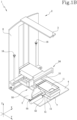
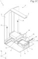
Figures 1A ,1B and1C are perspective views of three different operating configurations of an embodiment of the apparatus according to the invention; -
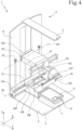
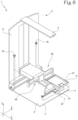
Figures 2 to 12 illustrate the apparatus ofFigures 1A ,1B and1C in different configurations, that is, with some elements located in different positions. - It should be noted that all the drawings are schematic and are therefore not representative of the actual dimensions of the system.
- The
numeral 1 denotes a medical apparatus for X-ray analysis. - The
apparatus 1 can allow a biopsy examination to be performed. - The
apparatus 1 comprises amachine 2 for allowing a diagnosis, equipped with: - at least one
source 3 configured to emit X-rays, - at least one
X-ray detector 4 defining a detection plane S; - a
probe 50 equipped with aneedle 51 for the treatment of the body of a patient; - an
immobiliser 10 comprising animmobilising element 11; - a supporting frame 6, supporting the at least one
source 3, the at least oneX-ray detector 4, theimmobiliser 10 and theprobe 50; - a control unit U connected at least to the
source 3 and to theX-ray detector 4. - According to the invention, the
probe 50 is connected to the supporting frame 6 movably along a first axis X, along a second direction Y perpendicular to the first direction X and along a third direction Z at right angles to the detection plane S, the first direction X and the second direction Y lying in a plane parallel to the detection plane S, theapparatus 1 is configured for moving saidprobe 50 in thezone 5 above theimmobiliser 10 and allow a positioning of theneedle 51, along the first direction X, selectively in thezone 5 above theimmobiliser 10 and in the right and left side relative to the immobiliser 10.According to an aspect of the invention, theapparatus 1 comprises afirst actuator 101 configured to move theprobe 50 along the first direction X. - According to an aspect of the invention, the
apparatus 1 comprises asecond actuator 102 configured to move theprobe 50 along the second direction Y. - According to an aspect of the invention, the
apparatus 1 comprises athird actuator 103 configured to move theprobe 50 along the third direction Z. According to another aspect, theimmobiliser 10 is connected to the supporting frame 6 and is movable, independently of theprobe 50, at least along the third direction Z. - According to an aspect of the invention, the
apparatus 1 comprises afourth actuator 104 configured to move theimmobiliser 10 along the third direction Z. - According to an aspect of the invention, the
immobiliser 10 is configured to allow a movement along the third direction Z for a stroke of between 10 mm and 200 mm, more preferably between 50 mm and 120 mm, even more preferably for a stroke of between 70 mm and 90 mm. - According to an aspect of the invention, the
apparatus 1 comprises at least oneknob 16 for locking theimmobiliser 10. Thelocking knob 16 is designed to lock the movement of theimmobiliser 10 along the third direction Z. - The
immobiliser 10 is configured to immobilise abreast 15 of a patient. According to an aspect, theimmobiliser 10 is configured to compress thebreast 15. - The
breast 15 is illustrated schematically in the accompanying drawings. Advantageously, once theimmobiliser 10 has been positioned in contact with thebreast 15 in order to immobilise it and compress it, the blocking of movement of theimmobiliser 10 along the third direction Z by means of thelocking knob 16 prevents movements of theimmobiliser 10 which could cause pain for the patient or errors during the examination procedures. In fact, a sudden movement of theimmobiliser 10 towards thebreast 15 would cause excessive compression and hence possible pain for the patient. Vice versa, an unexpected movement in the opposite direction would result in thebreast 15 not being correctly immobilised and compressed during an analysis procedure. - Advantageously, the
apparatus 1 according to the invention is particularly compact and allows a biopsy examination to be performed without repositioning thebreast 15 of the patient immobilised using theimmobiliser 10. In effect, theprobe 50 may be moved, selectively, that is to say, by means of a setting or action by the user, to the right or to the left relative to theimmobiliser 10. - The
probe 50, in its movement between the right and left parts of theimmobiliser 10, passes through the region above theimmobiliser 10. - It should also be noted that the
probe 50 may also be positioned in the region above theimmobiliser 10. - This facilitates examination of the patient both with regard to the positioning of the
breast 15 and with regard to the operations to be performed by the dedicated medical staff. - According to an aspect of the invention, the
probe 50 is configured to allow a movement along the first direction X for a stroke of between 50 mm and 400 mm, more preferably between 60 mm and 200 mm, even more preferably for a stroke of between 80 mm and 120 mm. - It should be noted that the above-mentioned positioning to the right or to the left of the
probe 50 relative to theimmobiliser 10 is to be considered along the first direction X. - According to an aspect of the invention, the
probe 50 is configured to allow a movement along the second direction Y for a stroke of between 50 mm and 300 mm, more preferably between 60 mm and 200 mm, even more preferably for a stroke of between 80 mm and 120 mm. - According to an aspect of the invention, the
probe 50 is configured to allow a movement along the third direction Z for a stroke of between 150 mm and 350 mm, more preferably between 200 mm and 300 mm, even more preferably for a stroke of between 240 mm and 280 mm. - According to another aspect, said
probe 50 is a biopsy probe. - It should also be noted that the
immobiliser 10 has anupper opening 14, through which theneedle 51 can pass to perform a biopsy examination. The opening 14 is preferably square in shape. - Preferably, the side of this opening is between 30 mm and 70 mm; still more preferably, between 40 mm and 60 mm.
- The
immobilising element 11 of theimmobiliser 10 extends along the first direction X between 80 mm and 200 mm and extends along the second direction Y between 80 mm and 250 mm. - It should be noted that the
immobiliser 10 is movable, preferably continuously, independently of theprobe 50, along the first direction X. - According to an aspect of the invention, the
immobiliser 10 is configured to allow a movement along the first direction X for a stroke of between 50 mm and 120 mm, more preferably between 60 mm and 100 mm, even more preferably for a stroke of between 70 mm and 90 mm. - According to an aspect of the invention, the
apparatus 1 comprises afifth actuator 105 configured to move theimmobiliser 10 along the first direction X. - According to another aspect, the
immobiliser 10 is movable, preferably continuously, independently of theprobe 50, along the second direction Y. According to an aspect of the invention, theimmobiliser 10 is configured to allow a movement along the second direction Y for a stroke of between 50 mm and 120 mm, more preferably between 60 mm and 100 mm, even more preferably for a stroke of between 70 mm and 90 mm. - According to an aspect of the invention, the
apparatus 1 comprises asixth actuator 106 configured to move theimmobiliser 10 along the second direction Y. - It should also be noted that the
probe 50 is movable in rotation about a first axis of rotation A1. The first axis A1 is angularly positioned relative to the third direction Z, that is to say, angularly positioned relative to a direction perpendicular to the detection plane S, preferably by an angle of between 0° and 10°, more preferably between 4° and 8°. - According to an aspect of the invention, the
probe 50 is configured to allow the rotation about the first axis of rotation A1 of between 0° and 250°, considering that the configurations wherein theprobe 50 is positioned with theneedle 51 parallel to the detection plane S to the left and to the right of theimmobiliser 10 relative to the first direction X correspond, respectively, to an angle of 35° and 215°. - According to an aspect of the invention, the
apparatus 1 comprises aseventh actuator 107 configured to move theprobe 50 in rotation about the first axis of rotation A1. - Advantageously, the rotation of the
probe 50 about the first axis of rotation A1, together with the movements of theprobe 50 itself along the first direction X, the second direction Y and the third direction Z, allows theneedle 51 of theprobe 50 to approach thebreast 15 from different operating positions. - According to another aspect, the
machine 2 comprises a member 7 for supporting thebreast 15, removably connected to the supporting frame 6 and positioned between the detection plane S and theimmobiliser 10. The member 7 for supporting thebreast 15 is movable along the first direction X. - According to an aspect, the member 7 for supporting the
breast 15 is movable along the first direction X independently, preferably continuously, with respect to theimmobiliser 10. - According to an aspect of the invention, the member 7 for supporting the
breast 15 is configured to allow a movement along the first direction X for a stroke of between 50 mm and 120 mm, more preferably between 60 mm and 100 mm, even more preferably for a stroke of between 70 mm and 90 mm. - According to an aspect of the invention, the
apparatus 1 comprises aneighth actuator 108 configured to move the member 7 for supporting thebreast 15 along the first direction X. - According to an aspect, the
machine 2 comprises asystem 8 for covering thedetector 4 and/or the member 7 for supporting thebreast 15, removably couplable to thedetector 4 and/or to the member 7 for supporting thebreast 15. - The
covering system 8 comprises a casing, which may be positioned above thedetector 4, to be replaced for each examination; this guarantees the safety of themachine 2 from the hygiene and medical points of view. According to another aspect, thecovering system 8 comprises a casing which may be positioned above the member 7 for supporting thebreast 15. - More generally speaking, it should be noted that the casing of the
covering system 8 may enclose one or both of thedetector 4 and the supporting member 7. - Preferably, the casing is made of plastic material (and is of the disposable type, that is to say, it can be replaced after each use of the machine).
- The
system 8 for covering thedetector 4 and/or the member 7 for supporting thebreast 15 is disposable or sterilisable. - According to another aspect, the
machine 2 comprises at least onesensor 9 connected to the control unit U and configured to detect impacts of theprobe 50 in the movement of the probe, along the third direction Z and/or along the first direction X and/or the second direction Y. - In this way, advantageously, it is possible to check whether during the examination there have been impacts by the probe 50: this makes it possible to detect unexpected collisions with machine elements or parts of the human body of the patient or of the operator.
- Preferably, the
sensor 9 is a force sensor; more preferably a sensor of the load cell type. - According to an aspect, the
probe 50 comprises aneedle 51 and adevice 52 for supporting theneedle 51. - According to an aspect of the invention, the supporting
device 52 of theneedle 51 is configured to allow a translation for a stroke of between 140 mm and 220 mm, preferably between 160 mm and 200 mm. - In other words, the supporting
device 52 of theneedle 51 is configured for a movement which allows theneedle 51, in use, to advance or to withdraw relative to the biopsy sampling zone and therefore relative to thebreast 15. - According to an aspect of the invention, the
apparatus 1 comprises aninth actuator 109 configured to move the supportingdevice 52 of theneedle 51 towards and away, in use, from thebreast 15. - According to one aspect, the
apparatus 1 comprises acontrol knob 55 configured to translate the supportingdevice 52 of theneedle 51 to allow theneedle 51, in use, to move forward or to withdraw relative to the biopsy sampling zone and therefore relative to thebreast 15. - The
control knob 55 allows the supportingdevice 52 of theneedle 51 to be moved manually and/or to lock it, again manually, in a predetermined position. - The
apparatus 1 comprises adistance sensor 53 connected to the control unit U and configured to measure the distance between the tip of theneedle 51 and an end of the supportingdevice 52 of theneedle 51. Advantageously, according to this aspect, it is possible to check the length of theneedle 51, so as to check whether the machine settings are correct for theneedle 51 in use. - The
distance sensor 53 may be of any type, for example of the optical type or of the potentiometric strips type. - The control unit U is configured to emit a signal if the length measured by the
distance sensor 53 of saidneedle 51 does not correspond to a preset length of a needle. - In that sense, the
machine 2 comprises an interface configured to allow selection of a parameter relating to the length of theneedle 51 in use. According to another aspect, theprobe 50 comprises aneedle holder guide 54 and thedistance sensor 53 is positioned on theneedle holder guide 54. - According to another aspect, the control unit U is configured to provide a method for identifying the position of the
immobiliser 10 and/or a physical characteristic of thebreast 15 of the patient, wherein it activates theX-ray source 3 and identifies the position of theimmobiliser 10 by analysing the signal received from thedetector 4. - In short, when a method for identifying the position of the
immobiliser 10 and/or a physical characteristic of the patient'sbreast 15 is set, it is possible to establish the position of theimmobiliser 10 by means of an X-ray analysis. This is particularly useful, since it is possible, by means of an analysis performed in the machine, without providing an additional dose of radiation to the patient, to acquire the positioning of theimmobiliser 10 with respect to thebreast 15, so as to be able to derive indications of movement of theprobe 50 for the biopsy sample. - Moreover, in this manner, it is also possible to detect a physical characteristic of the patient's
breast 15 for various purposes, for example to check its position with respect to theimmobiliser 10 itself. - The physical characteristic of the patient's
breast 15 means, by way of a non-limiting example, the shape, volume, colour, edge, etc. - According to an aspect of the invention, the
apparatus 1 is configured for moving theX-ray source 3 along an arc in different positions for acquiring stereotaxic and tomographic images. - The arc has a centre C with a position between the
source 3 and theX-ray detector 4. - Preferably, the distance between the centre C of the arc and the
detector 4 is less than the distance between the centre C of the arc and thesource 3. - Preferably, the distance between the centre C of the arc and the
detector 4 is less than or equal to 150 mm, even more preferably less than or equal to 100 mm. - Advantageously, the possibility of positioning the
X-ray source 3 in different positions along the arc makes it possible to acquire stereotaxic or tomographic images of thebreast 15 and/or of the immobiliser. Advantageously, the images allow a position of theimmobiliser 10 and/or of thebreast 15 and/or any lesions of thebreast 15 itself to be identified. Advantageously, these stereotaxic or tomographic images can be acquired during the biopsy procedure, in order mainly to guide theprobe 50 during the biopsy examination, or before the procedure, for example to set up an operating plane for moving theprobe 50. - Advantageously, the stereotaxic or tomographic images allow reliable information to be obtained even deep inside the
breast 15. - According to an aspect, according to these images, the control unit U is configured to move the
probe 50 along the first direction X, the second direction Y and the third direction Z. - In fact, it should be noted that when the
needle 51 is inserted into thebreast 15, the tissues of thebreast 15, including any lesion, can move. For this reason, a modification of the path of theneedle 51 may be required for the biopsy sampling. The stereotaxic or tomographic images allow the detection of any modification in the position of the tissues and the control unit U is configured to consequently move theprobe 50, and therefore theneedle 51. - According to another aspect, the
machine 2 comprising aviewing system 20 configured to capture images of theimmobiliser 10 and/or of theprobe 50 and/or of the member 7 for supporting thebreast 15 and/or of thebreast 15, to identify the position or the physical characteristics of one or more of saidimmobiliser 10,probe 50, member 7 for supporting thebreast 15, relative to a predetermined reference system. - Advantageously, in this way, it is possible to obtain information useful for operation of the machine, through the
viewing system 20 itself, in particular with regard to the position of some elements of themachine 2 or of thebreast 15 of the patient. - Preferably, the
viewing system 20 comprises one or more video cameras, preferably of the stereo type. - The
viewing system 20 may also perform the function of anti-collision checking, since the control unit U may be configured to allow a check of the relative positioning of the various components of the machine to identify any abnormal positions which can correspond to a collision condition. - Generally speaking, it should be noted that the information regarding the positions of the
breast 15 and/or lesions in thebreast 15 and/or components of themachine 2 makes it possible to use all the possible configurations of theapparatus 1 described in this invention in order to optimise the biopsy sampling procedure. In particular, among the other advantages, the optimisation of the configuration of theapparatus 1 allows the sampling path followed by theprobe 50 to be minimised and a cut to be made on thebreast 15 as small as possible. - According to another aspect, the
probe 50 comprises at least one control handle 55 configured to move theprobe 50 along the third direction Z. According to another aspect, theprobe 50 comprises amovement system 56 with guides (57A, 57B) and slides (58A, 58B). - The slides (58A, 58B) are movable along said guides (57A, 57B) for movement of the
probe 50 along the first direction X and the second direction Y. - According to another aspect, the
movement system 56 withguides first guide 57A and afirst slide 58A, movable along saidfirst guide 57A, for the movement along the first direction X. - According to another aspect, the
movement system 56 with guides (57A, 57B) and slides (58A, 58B) comprises asecond guide 57B and asecond slide 58B, movable along saidsecond guide 57B, for the movement along the second direction Y. - According to yet another aspect, the
immobiliser 10 comprises at least afirst tray 12, designed for collecting fluids or organic materials. Advantageously, in this way, it is possible to collect any bodily fluids (e.g. blood) which may come out during the biopsy operation on thebreast 15 of the patient: this increases the hygiene-medical safety of themachine 2. According to another aspect, theimmobiliser 10 comprises at least asecond tray 13, designed to collect fluids or organic materials, saidsecond tray 13 being associated with the immobilisingelement 11. - Preferably, the
second tray 13 is made of a deformable material, for example silicone; in this way, it can advantageously be flattened by the immobilisingelement 11 and/or by the member 7 for supporting thebreast 15. - Preferably, the
second tray 13 is made of silicone. - The
second tray 13 is particularly useful in the case of a biopsy performed laterally with the needle 51: in this case, the fluids are collected by thesecond tray 13. - It should also be noted that the immobilising
element 11 may be replaced from one patient to another, also allowing the replacement of the first andsecond trays 12, 13: this increases the hygiene-medical safety of the machine itself. - According to another aspect, the
probe 50 is connected to the supporting frame 6 by afirst hinge 30, so as to rotate according to a second axis A2 parallel to the detection plane S. - The second axis A2 is parallel to the first direction X.
- According to an aspect, the rotation of the
probe 50 about the second axis A2 is between -15° and 15°, even more preferably between -10° and 10°. The angle of rotation 0° of theprobe 50 is illustrated inFigure 2 . InFigure 2 , theneedle 51 of theprobe 50 lies on a plane at a right angle to the detection plane S. - According to an aspect of the invention, the
apparatus 1 comprises atenth actuator 110 configured to move theprobe 50 in rotation about the second axis of rotation A2. - According to an embodiment not illustrated in the accompanying drawings, the
first hinge 30 is positioned in a zone of themovement system 56 withguides slides immobiliser 10 is connected to the supporting frame 6 by asecond hinge 31, so as to rotate according to a third axis A3 parallel to the detection plane S. - The third axis A3 is parallel to the first direction X.
- According to an aspect, considering an angle of 0° when a lower surface of the
immobiliser 10 is parallel to the detector 4 (as illustrated for example inFigure 1A ), the rotation of theimmobiliser 10 about the third axis A3 is between -15° and 15°, even more preferably between -10° and 10°. According to an aspect of the invention, theapparatus 1 comprises an elevenactuator 111 configured to move theimmobiliser 10 in rotation about the third axis of rotation A3. - Advantageously, the
immobiliser 10 can therefore be inclined at various angles towards thebreast 15, in such a way as to adapt to each morphology of it. In particular, in this way, themachine 2 is able to adapt in an optimum manner also to small and/ordense breasts 15. - According to an aspect of the invention, the
apparatus 1 comprises afurther sensor 32, preferably a force sensor, more preferably a sensor of the load cell type, configured to detect the pressure of theimmobiliser 10 on thebreast 15 and/or any impacts of theimmobiliser 10. - The
further sensor 32 is configured for communicating with the control unit U. - The control unit U is configured to control the
eleventh actuator 111 as a function of the measurements of thefurther sensor 32. - According to an aspect, the
immobiliser 10 and each element of theapparatus 1 involved in moving theimmobiliser 10 are made in such a way as to not have any cavities or point which can facilitate the collection of organic materials or dirt in general. - Advantageously, this makes these elements of the
apparatus 1 easily sterilisable which, in use, may be in direct contact with the patient'sbreast 15. - It should be noted that the
apparatus 1 is configured to be positioned, in use, both horizontally and vertically, that is to say, themachine 2 can have the detection plane S of theX-ray detector 4 both parallel to the horizontal and parallel to the vertical. - According to an aspect of the invention, the control unit U is configured to control one or more between the
first actuator 101,second actuator 102,third actuator 103,fourth actuator 104,fifth actuator 105,sixth actuator 106,seventh actuator 107,eighth actuator 108,ninth actuator 109,tenth actuator 110 andeleventh actuator 111. - According to an aspect of this invention, one or more between the
first actuator 101,second actuator 102,third actuator 103,fourth actuator 104,fifth actuator 105,sixth actuator 106,seventh actuator 107,eighth actuator 108,ninth actuator 109,tenth actuator 110 andeleventh actuator 111 comprises a motor not illustrated in the accompanying drawings, preferably an electric motor. - The drawings will now be briefly described in relation to the positioning of some parts of the
machine 2. -
Figure 1A shows themachine 2 with theprobe 50 with theneedle 51 perfectly vertical and positioned in thezone 5 above theimmobiliser 10 for access to thebreast 15 through theopening 14 of the immobilisingelement 11. -
Figures 1B and1C illustrate themachine 2 with theprobe 50 with theneedle 51 on the left and right sides, respectively, with respect to theimmobiliser 10 for a lateral access to thebreast 15, with respect to the first direction X. -
Figure 2 shows themachine 2 with theprobe 50 with theneedle 51 perfectly vertical and positioned in thezone 5 above theimmobiliser 10 at theopening 14 of the immobilisingelement 11. -
Figure 3 illustrates themachine 2 with theprobe 50 with theneedle 51 rotated with respect to the first axis A1 and positioned in thezone 5 above theimmobiliser 10 at theopening 14 of the immobilisingelement 11. -
Figures 4 and5 illustrate themachine 2 with theprobe 50 with theneedle 51 rotated relative to the first axis A1 (by 90°) and with the immobilisingelement 11 positioned, along the second direction Y, respectively at the front and rear. -
Figure 6 illustrates themachine 2 with part of theprobe 50 removed. -
Figure 7 shows themachine 2 with the immobilisingelement 11 and the member 7 for supporting thebreast 15 in a central position and theprobe 50 located above the immobilisingelement 11; in this drawing, the immobilisingelement 11 is raised with respect to the member 7 for supporting thebreast 15. -
Figure 8 shows themachine 2 with the immobilisingelement 11 and the member 7 for supporting thebreast 15 in the right-hand position and theprobe 50 positioned laterally, on the left, with respect to the immobilisingelement 11, with respect to the first direction X; a lateral biopsy may be performed in this configuration. -
Figure 9 illustrates themachine 2 with theprobe 50 with theneedle 51 rotated with respect to the second axis A2 and positioned in thezone 5 above theimmobiliser 10 at theopening 14 of the immobilisingelement 11. -
Figure 10 shows themachine 2 with theprobe 50 with theneedle 51 rotated with respect to the second axis A2 and also rotated with respect to the first axis A1 and positioned in thezone 5 above theimmobiliser 10 at theopening 14 of the immobilisingelement 11. -
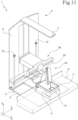
Figure 11 shows themachine 2 with theprobe 50 with theneedle 51 positioned in thezone 5 above theimmobiliser 10 at theopening 14 of the immobilisingelement 11 and with thecovering system 8 of thedetector 4 and/or of the member 7 for supporting thebreast 15 coupled to thedetector 4 and to the member 7 for supporting thebreast 15. -
Figure 12 illustrates themachine 2, highlighting various possible positions which theX-ray source 3 may adopt. -
Figures 2 to 10 and12 schematically illustrate, above the supporting member 7, abreast 15. - According to another aspect, a method is also defined, comprising the steps of:
- preparing:
- at least one
source 3 configured to emit X-rays, - at least one
X-ray detector 4 defining a detection plane S, - a
probe 50 equipped with aneedle 51 for the treatment of the body of a patient, - an
immobiliser 10 comprising an immobilisingelement 11, - a supporting frame 6, supporting the at least one
source 3, the at least oneX-ray detector 4, theimmobiliser 10 and theprobe 50, - a control unit U connected at least to the
source 3 and to the X-ray detector (4);
- at least one
- positioning a patient with the
relative breast 15 resting on the detection plane S; - moving the immobilising
element 11 along a third direction Z at right angles to the detection plane S, to compress thebreast 15 between theimmobiliser 10 and the detection plane S; - moving the
probe 50 along a first direction X, along a second direction Y perpendicular to the first direction X and along the third direction Z at a right angle to the detection plane S and moving theprobe 50 in thezone 5 above theimmobiliser 10 to allow a positioning of theneedle 51, along the first direction X, selectively in thezone 5 above theimmobiliser 10, on the right or left side relative to theimmobiliser 10, wherein said movement of theprobe 50 along at least the third direction Z is performed irrespective of the above-mentioned movement of the immobilisingelement 11 along the third direction Z; - reconstructing at least one image of the
breast 15 by analysing the X-rays emitted by thesource 3, passing through thebreast 15 and received by thedetector 4. - This method is a method for generating an image of the
breast 15 of a patient by means of the emission and the detection of X-rays. - According to an aspect, the step of reconstructing at least one image of the
breast 15 comprises a first step of reconstructing at least one image of thebreast 15 before moving theprobe 50 along the first direction X, the second direction Y and the third direction Z. - The step of moving the
probe 50 is a function of the at least one image of thebreast 15. - According to an aspect, the step of reconstructing at least one image of the
breast 15 comprises a second step of reconstructing at least one image of thebreast 15 after the step of moving theprobe 50 along the first direction X, the second direction Y and the third direction Z. - According to another aspect, the method comprises the step of preparing a member 7 for supporting the
breast 15 for resting thebreast 15, and positioning said member 7 for supporting thebreast 15 between the detection plane S and theimmobiliser 10. - According to another aspect, the method comprises the following steps:
- setting the control unit U to activate a mode of identifying a physical characteristic or position of the
immobiliser 10, theprobe 50 and/or the member 7 for supporting thebreast 15 and/or of thebreast 15; - activating the
X-ray source 3; - and analysing the X-ray signal received from the
detector 4 to identify the physical characteristic or position of theimmobiliser 10, theprobe 50, the member 7 for supporting thebreast 15 and/or of thebreast 15. - According to yet another aspect, the method comprises the following steps:
- preparing a
viewing system 20; - configuring the
viewing system 20 to capture images of theimmobiliser 10 and/or of theprobe 50 and/or of the member 7 for supporting thebreast 15 and/or of thebreast 15; - analysing the images of the
viewing system 20 to identify a physical characteristic or the position of saidimmobiliser 10,probe 50, member 7 for supporting thebreast 15 orbreast 15. - According to an aspect of the invention, the method comprises the steps of:
- moving the
X-ray source 3 along an arc in a plurality of different positions for acquiring stereotaxic or tomographic images; - acquiring stereotaxic or tomographic images of the
breast 15 and/or of theimmobiliser 10 in said different positions; - analysing these images to identify a position of the
immobiliser 10 and/or of thebreast 15 and/or of a lesion in thebreast 15; - moving the
probe 50 according to that position of theimmobiliser 10 and/or of thebreast 15 and/or of a lesion in thebreast 15 identified. According to a further aspect, the method comprises the steps of: - preparing at least one
system 8, which is disposable or sterilisable, for covering thedetector 4 and/or the member 7 for supporting thebreast 15; - removably coupling the
covering system 8 to thedetector 4 and/or to the member 7 for supporting thebreast 15; - carrying out an examination of the
breast 15 of a patient; - uncoupling the
covering system 8 from thedetector 4 and/or from the member 7 for supporting thebreast 15 and sterilising thecovering system 8. - According to another aspect of the method, the
probe 50 is a biopsy probe and the method comprises the steps of: - setting the control unit U to activate a method of targeting the
needle 51 during biopsy; - activating the
X-ray source 3 in order to capture at least two stereoscopic images; - analysing said stereoscopic images to identify the position of a region of the
breast 15 of a patient under examination; - comparing said position identified with a previous stored position of said region of the
breast 15 of a patient under examination; - deriving, as a function of said comparison, amplitudes of movement of said
needle 51 of theprobe 50 and movement of theneedle 51, as a function of said amplitudes of movement, to reach with theneedle 51 the region of thebreast 15 of a patient under examination. - According to another aspect, the method comprises a step of moving the immobilising
element 11 along the first direction X and/or the second direction Y. - According to yet another aspect, the method comprises a step of moving the member 7 for supporting the
breast 15 along the first direction X and/or the second direction Y. - According to yet another aspect, the method comprises a step of rotating the
probe 50, about a first axis of rotation A1, angularly positioned relative to the third direction Z, that is, angularly positioned relative to a direction perpendicular to the detection plane S. - According to yet another aspect, the method comprises a step of rotating the
probe 50, about a second axis A2, parallel to the detection plane S and parallel to the first direction X. - According to yet another aspect, the method comprises a step of rotating the
immobiliser 10, about a third axis A3, parallel to the detection plane S and parallel to the first direction X. - Advantageously, the method proposed allows an image of the
breast 15 to be reconstructed by emitting X-rays in a particularly simple way, simplifying the operations for positioning thebreast 15 of the patient during the examination.
Claims (16)
- A medical apparatus (1) for X-ray analysis, comprising:- a machine (2) for allowing a diagnosis, equipped with:- at least one source (3) configured to emit X-rays,- at least one X-ray detector (4) defining a detection plane (S),- a biopsy probe (50) equipped with a needle (51) for the treatment of the body of a patient,- an immobiliser (10) comprising an immobilising element (11),- a supporting frame (6), supporting the at least one source (3), the at least one X-ray detector (4), the immobiliser (10) and the probe (50);- a control unit (U) connected at least to the source (3) and to the X-ray detector (4);the apparatus (1) being characterised in that:- the probe (50) is connected to the supporting frame (6) movably along a first axis (X), along a second direction (Y) perpendicular to the first direction (X) and along a third direction (Z) at right angles to the detection plane (S), the first direction (X) and the second direction (Y) lying in a plane parallel to the detection plane (S), the apparatus (1) being configured for moving said probe (50) in the zone (5) above the immobiliser (10) and allow a positioning of the needle (51), along the first direction (X), selectively in the zone (5) above the immobiliser (10) and in the right and left side relative to the immobiliser (10);- the immobiliser (10) is connected to the supporting frame (6) and is movable, independently of the probe (50), at least along the third direction (Z).
- The apparatus (1) according to any of the foregoing claims, wherein the immobiliser (10) is movable, continuously, independently of the probe (50), along the first direction (X).
- The apparatus (1) according to any one of the preceding claims, wherein the immobiliser (10) is movable independently of the probe (50), along the second direction (Y).
- The apparatus (1) according to any one of the preceding claims, wherein the probe (50) is movable in rotation about a first axis (A1) of rotation.
- The apparatus (1) according to any of the preceding claims, comprising a member (7) for supporting a breast (15), removably connected to the supporting frame (6) and positioned between the detection surface (S) and the immobiliser (10), wherein the member (7) for supporting the breast (15) is movable along the first direction (X).
- The apparatus (1) according to any of the preceding claims, comprising a system (8) for covering the detector (4) and/or the member (7) for supporting the breast (15), removably couplable to the detector (4) and/or to the member (7) for supporting the breast (15), said covering system (8) being disposable or sterilisable.
- The apparatus (1) according to any one of the preceding claims, comprising at least one sensor (9) connected to the control unit (U) and configured to detect impacts of the probe (50) in the movement of the probe, along the third direction (Z) and/or along the first direction (X) and/or the second direction (Y).
- The apparatus (1) according to any one of the preceding claims, wherein the probe (50) comprises a needle (51), a supporting device (52) for the needle (51), said apparatus (1) comprising a distance sensor (53) connected to the control unit (U) and configured to measure the distance between the tip of the needle (51) and the supporting device (52) of the needle (51).
- The apparatus (1) according to the preceding claim, wherein the probe (50) comprises a needle holder guide (54) and the distance sensor (53) is positioned on the needle holder guide (54).
- The apparatus (1) according to any one of the preceding claims, wherein the control unit (U) is configured to provide a mode for identifying the position of the immobiliser (10) and/or a physical characteristic of the breast (15) of the patient, wherein it activates the X-ray source (3) and identifies the position of the immobiliser (10) by analysing the signal received from the detector (4).
- The apparatus (1) according to any of the preceding claims, comprising a viewing system (20) configured to capture images of the immobiliser (10) and/or of the probe (50) and/or of the member (7) for supporting the breast (15) and/or of the breast (15), to identify the position or the physical characteristics of one or more of said immobiliser (10), probe (50), member (7) for supporting the breast (15), breast (15), relative to a predetermined reference system.
- The apparatus (1) according to any one of the preceding claims, wherein the probe (50) comprises a movement system (56) with guides (57A, 57B) and slides (58A, 58B), movable along said guides (57A, 57B), for the movement along the first direction (X) and the second direction (Y), wherein the movement system (56) with guides (57A, 57B) and slides (58A, 58B) comprises a first guide (57A) and a first slide (58A), movable along said first guide (57A), for the movement along the first direction (X).
- The apparatus (1) according to claim 12, wherein the movement system (56) with guides (57A, 57B) and slides (58A, 58B) comprises a second guide (57B) and a second slide (58B), movable along said second guide (57B), for the movement along the second direction (Y).
- The apparatus (1) according to any one of the preceding claims, wherein the probe (50) is connected to the supporting frame (6) by a first hinge (30), so as to rotate according to a second axis (A2) parallel to the detection plane (S).
- The apparatus (1) according to any one of the preceding claims, wherein the immobiliser (10) is connected to the supporting frame (6) by a second hinge (31), so as to rotate according to a third axis (A3) parallel to the detection plane (S).
- A method comprising the following steps:- preparing:- at least one source (3) configured to emit X-rays,- at least one X-ray detector (4) defining a detection plane (S),- a probe (50), equipped with a needle (51), for the treatment of the body of a patient,- an immobiliser (10) comprising an immobilising element (11),- a supporting frame (6), supporting the at least one source (3), the at least one X-ray detector (4), the immobiliser (10) and the probe (50),- a control unit (U) connected at least to the source (3) and to the X-ray detector (4);- positioning a patient with a relative breast (15) resting on the detection plane (S);- moving the immobilising element (11) along a third direction (Z) at right angles to the detection plane (S), to compress the breast (15) between the immobiliser (10) and the detection plane (S);- moving the probe (50) along a first direction (X), along a second direction (Y) perpendicular to the first direction (X) and along the third direction (Z) at a right angle to the detection plane (S) and moving the probe (50) in the zone (5) above the immobiliser (10) to allow a positioning of the needle (51), along the first direction (X), selectively in the zone (5) above the immobiliser (10), on the right or left side relative to the immobiliser (10), wherein said movement of the probe (50) along at least the third direction (Z) is performed irrespective of the above-mentioned movement of the immobilising element (11) along the third direction (Z);- reconstructing at least one image of the breast (15) by analysing the X-rays emitted by the source (3), passing through the breast (15) and received by the detector (4).
Applications Claiming Priority (1)
| Application Number | Priority Date | Filing Date | Title |
|---|---|---|---|
| IT102022000002660A IT202200002660A1 (en) | 2022-02-14 | 2022-02-14 | MEDICAL ANALYSIS EQUIPMENT AND RELATED METHOD |
Publications (2)
| Publication Number | Publication Date |
|---|---|
| EP4226861A1 true EP4226861A1 (en) | 2023-08-16 |
| EP4226861B1 EP4226861B1 (en) | 2026-02-11 |
Family
ID=81392774
Family Applications (1)
| Application Number | Title | Priority Date | Filing Date |
|---|---|---|---|
| EP23156212.5A Active EP4226861B1 (en) | 2022-02-14 | 2023-02-13 | Medical analysis apparatus and relative method |
Country Status (5)
| Country | Link |
|---|---|
| US (1) | US20230255580A1 (en) |
| EP (1) | EP4226861B1 (en) |
| ES (1) | ES3063069T3 (en) |
| IT (1) | IT202200002660A1 (en) |
| PL (1) | PL4226861T3 (en) |
Citations (7)
| Publication number | Priority date | Publication date | Assignee | Title |
|---|---|---|---|---|
| US20110087132A1 (en) * | 2009-10-08 | 2011-04-14 | Hologic, Inc. | Needle Breast Biopsy System and Method for Use |
| EP2517627A1 (en) * | 2011-04-27 | 2012-10-31 | Fujifilm Corporation | Radiographic image capturing apparatus |
| EP3023076A1 (en) * | 2014-10-24 | 2016-05-25 | I.M.S. Internazionale Medico Scientifica S.r.l. | Apparatus for performing a biopsy on a patient's breast and computer-implemented method for defining a route for a biopsy needle through a patient's breast |
| US20160183898A1 (en) * | 2013-08-05 | 2016-06-30 | Cirdan Imaging Limited | A mammographic device |
| US20180035984A1 (en) * | 2016-08-03 | 2018-02-08 | Siemens Healthcare Gmbh | Biopsy unit |
| EP3476297A1 (en) * | 2017-10-27 | 2019-05-01 | IMS Giotto S.p.A. | Apparatus for the analysis of samples taken by biopsy |
| US20190209106A1 (en) * | 2018-01-05 | 2019-07-11 | Siemens Healthcare Gmbh | Positioning of an examination object in relation to an x ray device |
Family Cites Families (2)
| Publication number | Priority date | Publication date | Assignee | Title |
|---|---|---|---|---|
| JP5650467B2 (en) * | 2010-08-27 | 2015-01-07 | 富士フイルム株式会社 | Radiation imaging system |
| US10542951B2 (en) * | 2015-07-23 | 2020-01-28 | General Electric Company | Systems, methods, and devices for simplified high quality imaging of biopsy samples on a mammography machine |
-
2022
- 2022-02-14 IT IT102022000002660A patent/IT202200002660A1/en unknown
-
2023
- 2023-02-10 US US18/167,258 patent/US20230255580A1/en active Pending
- 2023-02-13 ES ES23156212T patent/ES3063069T3/en active Active
- 2023-02-13 PL PL23156212.5T patent/PL4226861T3/en unknown
- 2023-02-13 EP EP23156212.5A patent/EP4226861B1/en active Active
Patent Citations (7)
| Publication number | Priority date | Publication date | Assignee | Title |
|---|---|---|---|---|
| US20110087132A1 (en) * | 2009-10-08 | 2011-04-14 | Hologic, Inc. | Needle Breast Biopsy System and Method for Use |
| EP2517627A1 (en) * | 2011-04-27 | 2012-10-31 | Fujifilm Corporation | Radiographic image capturing apparatus |
| US20160183898A1 (en) * | 2013-08-05 | 2016-06-30 | Cirdan Imaging Limited | A mammographic device |
| EP3023076A1 (en) * | 2014-10-24 | 2016-05-25 | I.M.S. Internazionale Medico Scientifica S.r.l. | Apparatus for performing a biopsy on a patient's breast and computer-implemented method for defining a route for a biopsy needle through a patient's breast |
| US20180035984A1 (en) * | 2016-08-03 | 2018-02-08 | Siemens Healthcare Gmbh | Biopsy unit |
| EP3476297A1 (en) * | 2017-10-27 | 2019-05-01 | IMS Giotto S.p.A. | Apparatus for the analysis of samples taken by biopsy |
| US20190209106A1 (en) * | 2018-01-05 | 2019-07-11 | Siemens Healthcare Gmbh | Positioning of an examination object in relation to an x ray device |
Also Published As
| Publication number | Publication date |
|---|---|
| PL4226861T3 (en) | 2026-05-04 |
| US20230255580A1 (en) | 2023-08-17 |
| EP4226861B1 (en) | 2026-02-11 |
| ES3063069T3 (en) | 2026-04-15 |
| IT202200002660A1 (en) | 2023-08-14 |
Similar Documents
| Publication | Publication Date | Title |
|---|---|---|
| US20250177082A1 (en) | Needle breast biopsy system and method of use | |
| US12193853B2 (en) | Breast biopsy and needle localization using tomosynthesis systems | |
| US8467495B2 (en) | Radiographic image capturing apparatus and radiographic image capturing method | |
| JP6440177B2 (en) | Puncture robot | |
| JP4510053B2 (en) | Tissue cutting device | |
| US5386447A (en) | Mammographic screening and biopsy apparatus | |
| US8740810B2 (en) | Biopsy needle, sample extracting unit, biopsy apparatus, and method of controlling biopsy needle | |
| JP5376367B2 (en) | Radiation shield device | |
| US20040267121A1 (en) | Device and method for biopsy guidance using a tactile breast imager | |
| KR101700334B1 (en) | Cartridge and high-intensity focused ultrasonic sugical instrument | |
| US7826588B2 (en) | Device and method to generate digital x-ray images of a sample | |
| US20030109825A1 (en) | Medical device with a drive unit for a needle | |
| WO2014199641A2 (en) | Apparatus and method for supporting biopsy | |
| KR102459424B1 (en) | A real-time Biopsy manipulation robot device using a medical imaging equipment | |
| EP4226861B1 (en) | Medical analysis apparatus and relative method | |
| Magnusson et al. | CT-guided core biopsy using a new guidance device | |
| EP4356838A1 (en) | System and method for analyzing breast support environment | |
| JP3728437B2 (en) | Manipulator for use in closed magnetic resonance tomography equipment | |
| CN113273985A (en) | Intelligent physical examination all-in-one machine | |
| US12544020B2 (en) | Medical analysis apparatus |
Legal Events
| Date | Code | Title | Description |
|---|---|---|---|
| PUAI | Public reference made under article 153(3) epc to a published international application that has entered the european phase |
Free format text: ORIGINAL CODE: 0009012 |
|
| STAA | Information on the status of an ep patent application or granted ep patent |
Free format text: STATUS: THE APPLICATION HAS BEEN PUBLISHED |
|
| AK | Designated contracting states |
Kind code of ref document: A1 Designated state(s): AL AT BE BG CH CY CZ DE DK EE ES FI FR GB GR HR HU IE IS IT LI LT LU LV MC ME MK MT NL NO PL PT RO RS SE SI SK SM TR |
|
| P01 | Opt-out of the competence of the unified patent court (upc) registered |
Effective date: 20231113 |
|
| STAA | Information on the status of an ep patent application or granted ep patent |
Free format text: STATUS: REQUEST FOR EXAMINATION WAS MADE |
|
| 17P | Request for examination filed |
Effective date: 20240215 |
|
| RBV | Designated contracting states (corrected) |
Designated state(s): AL AT BE BG CH CY CZ DE DK EE ES FI FR GB GR HR HU IE IS IT LI LT LU LV MC ME MK MT NL NO PL PT RO RS SE SI SK SM TR |
|
| GRAP | Despatch of communication of intention to grant a patent |
Free format text: ORIGINAL CODE: EPIDOSNIGR1 |
|
| STAA | Information on the status of an ep patent application or granted ep patent |
Free format text: STATUS: GRANT OF PATENT IS INTENDED |
|
| INTG | Intention to grant announced |
Effective date: 20250414 |
|
| GRAJ | Information related to disapproval of communication of intention to grant by the applicant or resumption of examination proceedings by the epo deleted |
Free format text: ORIGINAL CODE: EPIDOSDIGR1 |
|
| STAA | Information on the status of an ep patent application or granted ep patent |
Free format text: STATUS: REQUEST FOR EXAMINATION WAS MADE |
|
| INTC | Intention to grant announced (deleted) | ||
| GRAP | Despatch of communication of intention to grant a patent |
Free format text: ORIGINAL CODE: EPIDOSNIGR1 |
|
| STAA | Information on the status of an ep patent application or granted ep patent |
Free format text: STATUS: GRANT OF PATENT IS INTENDED |
|
| INTG | Intention to grant announced |
Effective date: 20250905 |
|
| GRAS | Grant fee paid |
Free format text: ORIGINAL CODE: EPIDOSNIGR3 |
|
| GRAA | (expected) grant |
Free format text: ORIGINAL CODE: 0009210 |
|
| STAA | Information on the status of an ep patent application or granted ep patent |
Free format text: STATUS: THE PATENT HAS BEEN GRANTED |
|
| AK | Designated contracting states |
Kind code of ref document: B1 Designated state(s): AL AT BE BG CH CY CZ DE DK EE ES FI FR GB GR HR HU IE IS IT LI LT LU LV MC ME MK MT NL NO PL PT RO RS SE SI SK SM TR |
|
| REG | Reference to a national code |
Ref country code: CH Ref legal event code: F10 Free format text: ST27 STATUS EVENT CODE: U-0-0-F10-F00 (AS PROVIDED BY THE NATIONAL OFFICE) Effective date: 20260211 Ref country code: GB Ref legal event code: FG4D |
|
| REG | Reference to a national code |
Ref country code: CH Ref legal event code: R17 Free format text: ST27 STATUS EVENT CODE: U-0-0-R10-R17 (AS PROVIDED BY THE NATIONAL OFFICE) Effective date: 20260213 |
|
| REG | Reference to a national code |
Ref country code: NL Ref legal event code: FP |
|
| REG | Reference to a national code |
Ref country code: CH Ref legal event code: U11 Free format text: ST27 STATUS EVENT CODE: U-0-0-U10-U11 (AS PROVIDED BY THE NATIONAL OFFICE) Effective date: 20260301 |
|
| REG | Reference to a national code |
Ref country code: DE Ref legal event code: R096 Ref document number: 602023011729 Country of ref document: DE |
|
| REG | Reference to a national code |
Ref country code: IE Ref legal event code: FG4D |
|
| PGFP | Annual fee paid to national office [announced via postgrant information from national office to epo] |
Ref country code: NL Payment date: 20260220 Year of fee payment: 4 |
|
| PGFP | Annual fee paid to national office [announced via postgrant information from national office to epo] |
Ref country code: ES Payment date: 20260317 Year of fee payment: 4 |
|
| PGFP | Annual fee paid to national office [announced via postgrant information from national office to epo] |
Ref country code: DE Payment date: 20260220 Year of fee payment: 4 |
|
| PGFP | Annual fee paid to national office [announced via postgrant information from national office to epo] |
Ref country code: AT Payment date: 20260301 Year of fee payment: 4 |
|
| PGFP | Annual fee paid to national office [announced via postgrant information from national office to epo] |
Ref country code: BE Payment date: 20260220 Year of fee payment: 4 Ref country code: IT Payment date: 20260228 Year of fee payment: 4 |
|
| REG | Reference to a national code |
Ref country code: ES Ref legal event code: FG2A Ref document number: 3063069 Country of ref document: ES Kind code of ref document: T3 Effective date: 20260415 |
|
| PGFP | Annual fee paid to national office [announced via postgrant information from national office to epo] |
Ref country code: FR Payment date: 20260227 Year of fee payment: 4 |
|
| PGFP | Annual fee paid to national office [announced via postgrant information from national office to epo] |
Ref country code: CH Payment date: 20260301 Year of fee payment: 4 |