EP4226807A1 - An automatically opening box - Google Patents
An automatically opening box Download PDFInfo
- Publication number
- EP4226807A1 EP4226807A1 EP23156205.9A EP23156205A EP4226807A1 EP 4226807 A1 EP4226807 A1 EP 4226807A1 EP 23156205 A EP23156205 A EP 23156205A EP 4226807 A1 EP4226807 A1 EP 4226807A1
- Authority
- EP
- European Patent Office
- Prior art keywords
- automatically opening
- box
- sides
- opening box
- base
- Prior art date
- Legal status (The legal status is an assumption and is not a legal conclusion. Google has not performed a legal analysis and makes no representation as to the accuracy of the status listed.)
- Granted
Links
Images




Classifications
-
- A—HUMAN NECESSITIES
- A45—HAND OR TRAVELLING ARTICLES
- A45C—PURSES; LUGGAGE; HAND CARRIED BAGS
- A45C7/00—Collapsible or extensible purses, luggage, bags or the like
- A45C7/0059—Flexible luggage; Hand bags
- A45C7/0063—Flexible luggage; Hand bags comprising an integrated expansion device
-
- A—HUMAN NECESSITIES
- A45—HAND OR TRAVELLING ARTICLES
- A45C—PURSES; LUGGAGE; HAND CARRIED BAGS
- A45C7/00—Collapsible or extensible purses, luggage, bags or the like
- A45C7/0018—Rigid or semi-rigid luggage
- A45C7/0036—Rigid or semi-rigid luggage collapsible to a minimal configuration, e.g. for storage purposes
-
- B—PERFORMING OPERATIONS; TRANSPORTING
- B65—CONVEYING; PACKING; STORING; HANDLING THIN OR FILAMENTARY MATERIAL
- B65D—CONTAINERS FOR STORAGE OR TRANSPORT OF ARTICLES OR MATERIALS, e.g. BAGS, BARRELS, BOTTLES, BOXES, CANS, CARTONS, CRATES, DRUMS, JARS, TANKS, HOPPERS, FORWARDING CONTAINERS; ACCESSORIES, CLOSURES, OR FITTINGS THEREFOR; PACKAGING ELEMENTS; PACKAGES
- B65D85/00—Containers, packaging elements or packages, specially adapted for particular articles or materials
- B65D85/02—Containers, packaging elements or packages, specially adapted for particular articles or materials for annular articles
- B65D85/04—Containers, packaging elements or packages, specially adapted for particular articles or materials for annular articles for coils of wire, rope or hose
-
- A—HUMAN NECESSITIES
- A45—HAND OR TRAVELLING ARTICLES
- A45C—PURSES; LUGGAGE; HAND CARRIED BAGS
- A45C13/00—Details; Accessories
- A45C13/005—Hinges
- A45C13/007—Hinges with spring means
-
- A—HUMAN NECESSITIES
- A45—HAND OR TRAVELLING ARTICLES
- A45C—PURSES; LUGGAGE; HAND CARRIED BAGS
- A45C13/00—Details; Accessories
- A45C13/02—Interior fittings; Means, e.g. inserts, for holding and packing articles
-
- B—PERFORMING OPERATIONS; TRANSPORTING
- B65—CONVEYING; PACKING; STORING; HANDLING THIN OR FILAMENTARY MATERIAL
- B65D—CONTAINERS FOR STORAGE OR TRANSPORT OF ARTICLES OR MATERIALS, e.g. BAGS, BARRELS, BOTTLES, BOXES, CANS, CARTONS, CRATES, DRUMS, JARS, TANKS, HOPPERS, FORWARDING CONTAINERS; ACCESSORIES, CLOSURES, OR FITTINGS THEREFOR; PACKAGING ELEMENTS; PACKAGES
- B65D11/00—Containers having bodies formed by interconnecting or uniting two or more rigid, or substantially rigid, components made wholly or mainly of plastics material
- B65D11/18—Containers having bodies formed by interconnecting or uniting two or more rigid, or substantially rigid, components made wholly or mainly of plastics material collapsible, i.e. with walls hinged together or detachably connected
- B65D11/186—Containers having bodies formed by interconnecting or uniting two or more rigid, or substantially rigid, components made wholly or mainly of plastics material collapsible, i.e. with walls hinged together or detachably connected whereby all side walls are hingedly connected to the base panel and to each other to allow automatic collapsing and reerecting, e.g. by means of folds provided in the side walls and or in the base panel
-
- B—PERFORMING OPERATIONS; TRANSPORTING
- B65—CONVEYING; PACKING; STORING; HANDLING THIN OR FILAMENTARY MATERIAL
- B65D—CONTAINERS FOR STORAGE OR TRANSPORT OF ARTICLES OR MATERIALS, e.g. BAGS, BARRELS, BOTTLES, BOXES, CANS, CARTONS, CRATES, DRUMS, JARS, TANKS, HOPPERS, FORWARDING CONTAINERS; ACCESSORIES, CLOSURES, OR FITTINGS THEREFOR; PACKAGING ELEMENTS; PACKAGES
- B65D21/00—Nestable, stackable or joinable containers; Containers of variable capacity
- B65D21/08—Containers of variable capacity
-
- B—PERFORMING OPERATIONS; TRANSPORTING
- B65—CONVEYING; PACKING; STORING; HANDLING THIN OR FILAMENTARY MATERIAL
- B65D—CONTAINERS FOR STORAGE OR TRANSPORT OF ARTICLES OR MATERIALS, e.g. BAGS, BARRELS, BOTTLES, BOXES, CANS, CARTONS, CRATES, DRUMS, JARS, TANKS, HOPPERS, FORWARDING CONTAINERS; ACCESSORIES, CLOSURES, OR FITTINGS THEREFOR; PACKAGING ELEMENTS; PACKAGES
- B65D21/00—Nestable, stackable or joinable containers; Containers of variable capacity
- B65D21/08—Containers of variable capacity
- B65D21/086—Collapsible or telescopic containers
-
- B—PERFORMING OPERATIONS; TRANSPORTING
- B65—CONVEYING; PACKING; STORING; HANDLING THIN OR FILAMENTARY MATERIAL
- B65D—CONTAINERS FOR STORAGE OR TRANSPORT OF ARTICLES OR MATERIALS, e.g. BAGS, BARRELS, BOTTLES, BOXES, CANS, CARTONS, CRATES, DRUMS, JARS, TANKS, HOPPERS, FORWARDING CONTAINERS; ACCESSORIES, CLOSURES, OR FITTINGS THEREFOR; PACKAGING ELEMENTS; PACKAGES
- B65D29/00—Sacks or like containers made of fabrics; Flexible containers of open-work, e.g. net-like construction
-
- B—PERFORMING OPERATIONS; TRANSPORTING
- B65—CONVEYING; PACKING; STORING; HANDLING THIN OR FILAMENTARY MATERIAL
- B65H—HANDLING THIN OR FILAMENTARY MATERIAL, e.g. SHEETS, WEBS, CABLES
- B65H75/00—Storing webs, tapes, or filamentary material, e.g. on reels
- B65H75/02—Cores, formers, supports, or holders for coiled, wound, or folded material, e.g. reels, spindles, bobbins, cop tubes, cans, mandrels or chucks
- B65H75/34—Cores, formers, supports, or holders for coiled, wound, or folded material, e.g. reels, spindles, bobbins, cop tubes, cans, mandrels or chucks specially adapted or mounted for storing and repeatedly paying-out and re-storing lengths of material provided for particular purposes, e.g. anchored hoses, power cables
- B65H75/36—Cores, formers, supports, or holders for coiled, wound, or folded material, e.g. reels, spindles, bobbins, cop tubes, cans, mandrels or chucks specially adapted or mounted for storing and repeatedly paying-out and re-storing lengths of material provided for particular purposes, e.g. anchored hoses, power cables without essentially involving the use of a core or former internal to a stored package of material, e.g. with stored material housed within casing or container, or intermittently engaging a plurality of supports as in sinuous or serpentine fashion
-
- B—PERFORMING OPERATIONS; TRANSPORTING
- B65—CONVEYING; PACKING; STORING; HANDLING THIN OR FILAMENTARY MATERIAL
- B65H—HANDLING THIN OR FILAMENTARY MATERIAL, e.g. SHEETS, WEBS, CABLES
- B65H75/00—Storing webs, tapes, or filamentary material, e.g. on reels
- B65H75/02—Cores, formers, supports, or holders for coiled, wound, or folded material, e.g. reels, spindles, bobbins, cop tubes, cans, mandrels or chucks
- B65H75/34—Cores, formers, supports, or holders for coiled, wound, or folded material, e.g. reels, spindles, bobbins, cop tubes, cans, mandrels or chucks specially adapted or mounted for storing and repeatedly paying-out and re-storing lengths of material provided for particular purposes, e.g. anchored hoses, power cables
- B65H75/36—Cores, formers, supports, or holders for coiled, wound, or folded material, e.g. reels, spindles, bobbins, cop tubes, cans, mandrels or chucks specially adapted or mounted for storing and repeatedly paying-out and re-storing lengths of material provided for particular purposes, e.g. anchored hoses, power cables without essentially involving the use of a core or former internal to a stored package of material, e.g. with stored material housed within casing or container, or intermittently engaging a plurality of supports as in sinuous or serpentine fashion
- B65H75/362—Cores, formers, supports, or holders for coiled, wound, or folded material, e.g. reels, spindles, bobbins, cop tubes, cans, mandrels or chucks specially adapted or mounted for storing and repeatedly paying-out and re-storing lengths of material provided for particular purposes, e.g. anchored hoses, power cables without essentially involving the use of a core or former internal to a stored package of material, e.g. with stored material housed within casing or container, or intermittently engaging a plurality of supports as in sinuous or serpentine fashion with stored material housed within a casing or container
Definitions
- the present invention relates to an automatically opening box, in particular a box for storing a throwline and throw weights.
- throwlines have been stored in open containers, bags, boxes or buckets and also on a reel, all of which have inherent flaws due to space required in transport, ease of use and due to the problem of the throwlines becoming entangled when stored in this way.
- a modern arborist relies on a throwline and throw weight to install their climbing system prior to working at height. This mitigates the need to use heavy and dangerous ladder configurations. Storage and correct management of these lines therefore requires a bespoke solution.
- the present invention provides a foldable storage system that keeps the line held in position during transport to avoid tangles and has a reliable automatic opening function.
- US2010/059531 discloses a collapsible storage apparatus for fabrics.
- an automatically opening box comprising: a rectangular foldable base formed from two rectangular panels joined by a spine; with four sides, one side extending upwards from each edge of the rectangular base, characterised in that adjacent sides are connected at corners to define an open topped box and at least two corners include sprung hinges; a first set of two opposed sides each having at least two first fold lines and that fold with respect to the foldable base; a second set of two opposed sides that fold with respect to the base; and a pair of second fold lines which are provided on the opposed sides that are perpendicular to the spine of the foldable base; wherein the automatically opening box is configurable in two configurations, a first folded configuration in which the sides are collapsed to be parallel to the foldable base and the foldable base is folded along the spine and the first folded configuration is secured by a fastener; and a second deployed configuration in which the fastener is released and the sprung hinges act to deploy the sides and foldable base.
- the box can be stowed in a folded (collapsed) configuration and when the fastener is undone and the box is released, it automatically unfolds to a deployed configuration.
- This allows the box to be quickly deployed and the stored throwline to be utilised and has the advantage of not requiring the box to be carried in a deployed configuration that takes up more space and is more difficult to carry.
- the box is used to store throwline.
- Throwline needs to be stored in a flailed manner to allow for tangle free deployment.
- the first configuration where the sides are flapped down, restrains the flailed line until the box is opened, resulting in the line remaining flat and untangled.
- the box has a rectangular foldable base formed from two rectangular panels joined by a spine. This arrangement enables the base to be folded in half when in the folded configuration.
- the spine is a flexible hinge that permits the repeated folding and unfolding of the two panels that form the base.
- the base is square with a side extending upward from each edge of the square base to define a square box.
- the rectangular panels in the base are substantially rigid to define the shape of the box and to provide a solid structure suitable for carrying a throwline.
- the panels are formed from synthetic plastics, so as to be strong, durable and lightweight.
- the panels are covered in a flexible, durable, anti-rip material, such as a synthetic fabric such as a canvas.
- a flexible, durable, anti-rip material such as a synthetic fabric such as a canvas.
- the panels may be inserted into pockets formed in the material.
- the spine may be made of the same flexible material that covers the base panels.
- the spine is a living hinge between the two adjacent panels that are each covered by the flexible material.
- the panels may each be arranged in a pocket formed of the flexible material and the pockets are joined at the living hinge.
- the width of the spine defines the storage capacity of the box when in the folded configuration. For example, for a long line, a wider spine may be provided to provide a larger storage depth when the box is in the folded configuration.
- the spine width corresponds to the throwline and weights to be carried so that only the space required for the throwline and weights is provided, to minimise movement of the throwline when in the folded configuration so that the throwline is less likely to become tangled and to keep overall size of the box in the folded configuration as small as possible.
- the foldable base is joined to four sides, one side extending upward from each edge of the rectangular base wherein adjacent sides are connected at corners to define an open topped box.
- the sides connect to the base by means of a hinge and to each other by means of a hinge. In this way the sides are able to be folded to lay parallel to the folded base in the folded configuration.
- each side includes at least one substantially rigid panel to provide rigidity to the sides and to assist with defining the folding lines.
- the panels are shaped to correspond to hinges and fold lines so that a fold can be formed between adjacent panels.
- the sides comprise substantially rigid panels encased within a flexible material.
- the panels help to define the shape of the box when in the deployed configuration and help to prevent collapse of the sides. Additionally in windy conditions or when a foreign body makes contact with the box, the substantially rigid panels help maintain the shape of the box.
- the dimensions of the side panels also relate to the maximum height of the box due to the fold required at the fold lines in the panels.
- At least two corners include sprung hinges.
- the sprung hinges are biased to an open arrangement. Therefore when the fastener is released the sprung hinges are free to spring open, thereby deploying the sides and folded base.
- two opposed corners include the sprung hinges to ensure effective opening of the box.
- the sprung hinge includes at least one torsion spring.
- the torsion spring(s) is biased to at least 90 degrees and ideally slightly beyond 90 degrees to correspond to the open corner dimensions of the box and to add additional tension into the corners so that it remains open to at least 90 degrees.
- the sprung hinges are adapted to receive supporting rods that extend from the hinge along the sides in order to support and to unfold the sides.
- the length of the supporting rods corresponds to points at which the box folds. In this way the supporting rods do not prevent folding.
- an inner face of the sprung hinge has a channel or plurality of channels for receiving the rods.
- the channel may be defining by guiding portions that receive at least part of the rod, or a tube through which the rod, or part of the rod passes. In this way the rods can be easily inserted during assembly and can be removed and replaced if required.
- the sprung hinge is connected to the panels of the sides so as to be fixed in position. It is appreciated that the hinges may be covered by the flexible material of the sides so that the hinges and rods are not visible in use.
- the hinges are accessible, even when covered in material.
- an opening may be provided in the material, so that the hinges and rods can be accessed for repair or replacement.
- the hinges are fixed to an upper edge of each side to ensure that the sides are fully deployed.
- the rods are also arranged at the upper edge of the sides and therefore assist in tensioning the sides so that the box is opened fully and remains open as throwline is taken from or fed to the box.
- the box has a first set of two opposed sides each side of the first set of sides has at least two first fold lines that that permits the sides to fold with respect to the foldable base.
- the box has a pair of second fold lines that are aligned with the spine to enable the base and sides to be folded when in the configuration.
- the second fold lines are provided on opposed sides that are perpendicular to the spine.
- first fold lines may be on the same opposed sides as the pair of second fold lines, or on the other set of opposed sides.
- each of the first set of sides has three fold lines, Two mirrored first fold lines that bisect each half of the side into a pair of triangular sections and a second central fold line that corresponds to and aligns with the spine.
- the second set of opposed sides has no folds.
- each first side has at least two triangular substantially rigid panels and optionally four triangular substantially rigid panels.
- each of the first set of sides has one central second fold line that corresponds to the spine.
- Each of the second set of sides has two mirrored diagonal fold lines that divide the side into end triangular sections and a central trapezoidal section.
- each sprung hinge is arranged at opposed corners and each sprung hinge is adapted to hold three rods.
- One rod extends from one side of the hinge to a second side, extending the length of the second side.
- the rod is arranged in a pocket along an upper edge of the second side.
- Two rods extend from the other side of the hinge to extend along the first side.
- the rod lengths are different to each other and are shaped and dimensioned to correspond to the triangular panel so that the rods end at or before the fold lines to ensure that the first sides can fold.
- a first longer rod is provided at an upper edge of the first side and a second shorter rod is provided below.
- the folding arrangement of the base and sides enables the automatically opening box to be configurable in two configurations, a first folded configuration in which the sides are collapsed, and the base is folded along the spine and secured by a fastener; and a second deployed configuration in which the fastener is released and the sprung hinges act to deploy the sides and foldable base.
- the base can be folded along the spine and the fastener applied to lock the box in the collapsed configuration.
- the fastener is arranged on the underside of the base so that it is easily accessible to lock the box in the collapsed configuration.
- the fastener may be a clip, buckle, hook, press stud, hook and loop means or ties.
- part of the fastener is adjustable and/or has an elastic portion to allow for different amounts or size of line, a different number or size of weights, or positioning of the line, so that the box can be easily closed.
- a pocket is provided on an inner surface of the box for holding throw weights.
- the pocket is arranged in a corner of the box.
- the weight arranged in the corner it is more securely located and therefore there is no requirement for a cover to prevent escape of the weight(s) as the weight becomes held in the corner when folded.
- the pocket may be defined by a piece of material that is attached to one or more of the sides, and/or the base. Having a pocket for the weights ensures that the weight(s) is/are secured when the box is collapsed and therefore do not move with the throwline that may lead to tangling of the throwline.
- the pocket may be secured by an eyelet through the base.
- the eyelet provides a connection means, strength, and also provides a drainage point.
- one or more eyelets may be provided in the base for drainage.
- the box may include sections covered with a protective webbing to minimise wear.
- upper edges of the sides may include webbing to protect against wear from the throwline passing over the edges, and/or parts of the base that interface the ground may include webbing to reduce damage during use.
- the webbing may be extended to form a loop to provide a carry handle.
- an outer face of the base may include feet, such as studs, or patches that slightly elevate the box from the ground so as to minimise wear on the material part of the base.
- feet such as studs, or patches that slightly elevate the box from the ground so as to minimise wear on the material part of the base.
- an array of studs may be provided across the base, or four corner patches may be provided.
- the studs or corner patches may be formed from a strong, durable, anti-rip material such as synthetic plastics or rubber.
- an outer face of the box when in the folded configuration may include a tab for connection to a connector such as a carabiner. In this way the box can be easily connected to a wearer prior to use.
- an outer face of the box has touch pads which direct a user to a holding location for deployment and a holding location for closure where these touch pads denote the pinch points where a user applies force to collapse the box by overriding the torsion spring(s).
- the touch pads are ideally formed from a grippy material such as a textured rubber or silicone so that a user can easily and securely hold the box prior to folding and closing.
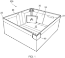
- Figure 1 shows a first embodiment 100 of the automatically opening throwline box.
- the box 100 has a base 10, four sides 20 and a pocket 30.
- the base is square with two rectangular panels (not visible) encased within a fabric cover.
- An upper edge of the sides 20 has a strip of webbing 21 to improve the strength of the edges.
- touch pads 90 On the cover there is a pair of touch pads 90 which indicate a holding point/ pinch points.
- the touch pads 90 also denote the location of the sprung hinges (not visible).
- the touch pads 90 have a textured surface for grip.
- the pocket 30 for storing one or more weights is arranged in a corner of the box.
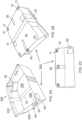
- FIGS. 2A, 2B, 2C , 3A and 3B show a second embodiment 200 of the invention. Like parts have the same reference numbers.
- the box 200 has two pockets 30 arranged in opposite corners of the box.
- a central spine 15 transects the base 10.
- the base has two rectangular panels (not visible), one on either side of the spine 15. The panels are enclosed within a material covering.
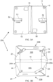
- the first opposed sides 20A have three fold lines 22, 23, 24.
- the second opposed sides 20B have no fold lines and include a single rectangular panel (not visible).
- the first fold lines 22, 24 enable the first opposed sides to collapsed against the base 10, followed by the second opposed sides 20B.
- the second fold line 23 that corresponds to the spine 15 enables the base 10 and sides 20A, 20B to be arranged in the first folded configuration.
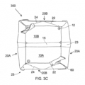
- Figure 3C there is shown a third embodiment of the invention in which the first opposed sides 20A each have one second fold line 23 that corresponds to the spine 15.
- the second opposed sides 20B each have two fold lines 22, 24 which enable the second set of opposed sides to be collapsed against the base 10, followed by the first opposed sides 20A.
- the second fold lines 23 enable the base 10 and sides 20A, 20B to be arranged in the first folded configuration.
- the box folds at all corners 25 where adjacent sides 20 join.
- the foldable base 10 has four feet 11 that each include an eyelet 12 that provide draining channels through the base of the box. On the outer face of the base the eyelets 12 project to form the feet 11 that elevate the box from the surface.
- the base has two touch pads 90 that when in the folded configuration indicate a holding position.
- the base 10 also has the fastener 50.
- the fastener is a strap 51 with a G-clip 52 which can be connected to a selected loop 53.
- the selection of loops 53 enables the G-clip to be secured at different positions depending on the arrangement and amount of line and weight(s).
- FIGS 4A and 4B details of the pockets 30 are shown.
- the pockets have stitching 70 to fix the pocket in position.
- Each pocket 30 has an eyelet 12 that passes through the base 10.
- An outer face of the eyelet 12 forms a foot 11.
- FIG 4C an upper edge of the side 20 is shown with a strip of webbing 80 that has stitching 82 to fix the webbing in position.
- the webbing 80 provides a reinforced layer to protect from wear during use.
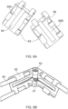
- the sprung hinges 60 have a torsion spring 61 that biases the hinge 60 to an open position at just over 90 degrees.
- Hinge plates 60A and 60B arranged in use along adjacent sides 20 of the box.
- Each hinge plate 60A, 60B has guides 62 for receiving supporting rods 65.
- the guides 62 define a channel along which a rod 65 is received. In this way the rods can be simply slid into and from the channels.
- the hinge plates are identical, each arranged in the opposite orientation to each other (see Figures 5A, 5B , 6A, 6B ) so as to reduce manufacturing costs. In this way two identical hinge plates can be meshed together to form the hinge 60.
- the hinge plates 60A, 60B are secured together by a pin 63 which also receives the torsion spring 61.
- Each arm 61A of the torsion spring 61 is received in a recess 64 on each hinge plate 60A, 60B.
- the hinge plates 60A, 60B are moulded to define an arcuate end point 66 for a distal end of the rod 65 and the rod also has a corresponding curved distal end so as to reduce wear and minimise movement of the rod in use.
- FIG. 7 a rear view of a hinge plate 60 is shown.
- the rear face has cut out portions to assist with tooling and to reduce the amount of material required to make the part. These cut out sections improve ease of manufacture and reduce the amount of material required, thereby reducing cost and weight.
- FIGS 8A to 8F show examples of touch pads. Each touch pad has a different patterned raised and lowered surface.
Landscapes
- Engineering & Computer Science (AREA)
- Mechanical Engineering (AREA)
- Purses, Travelling Bags, Baskets, Or Suitcases (AREA)
- Supplying Of Containers To The Packaging Station (AREA)
- Control And Other Processes For Unpacking Of Materials (AREA)
Abstract
Description
- The present invention relates to an automatically opening box, in particular a box for storing a throwline and throw weights.
- Historically throwlines have been stored in open containers, bags, boxes or buckets and also on a reel, all of which have inherent flaws due to space required in transport, ease of use and due to the problem of the throwlines becoming entangled when stored in this way.
- A modern arborist relies on a throwline and throw weight to install their climbing system prior to working at height. This mitigates the need to use heavy and dangerous ladder configurations. Storage and correct management of these lines therefore requires a bespoke solution.
- The present invention provides a foldable storage system that keeps the line held in position during transport to avoid tangles and has a reliable automatic opening function.
-
DE10113176 (HAEUSLER ) discloses a container for ropes used in the care of trees. -
US2006/231692 (SABOUNIJIAN discloses a panel or a container having a spring loop frame. -
US2010/059531 (SMITH ) discloses a collapsible storage apparatus for fabrics. - According to a first aspect of the present invention there is provided an automatically opening box comprising: a rectangular foldable base formed from two rectangular panels joined by a spine; with four sides, one side extending upwards from each edge of the rectangular base, characterised in that adjacent sides are connected at corners to define an open topped box and at least two corners include sprung hinges; a first set of two opposed sides each having at least two first fold lines and that fold with respect to the foldable base; a second set of two opposed sides that fold with respect to the base; and a pair of second fold lines which are provided on the opposed sides that are perpendicular to the spine of the foldable base; wherein the automatically opening box is configurable in two configurations, a first folded configuration in which the sides are collapsed to be parallel to the foldable base and the foldable base is folded along the spine and the first folded configuration is secured by a fastener; and a second deployed configuration in which the fastener is released and the sprung hinges act to deploy the sides and foldable base.
- In this way the box can be stowed in a folded (collapsed) configuration and when the fastener is undone and the box is released, it automatically unfolds to a deployed configuration. This allows the box to be quickly deployed and the stored throwline to be utilised and has the advantage of not requiring the box to be carried in a deployed configuration that takes up more space and is more difficult to carry.
- Preferably the box is used to store throwline. Throwline needs to be stored in a flailed manner to allow for tangle free deployment. The first configuration, where the sides are flapped down, restrains the flailed line until the box is opened, resulting in the line remaining flat and untangled.
- The box has a rectangular foldable base formed from two rectangular panels joined by a spine. This arrangement enables the base to be folded in half when in the folded configuration. The spine is a flexible hinge that permits the repeated folding and unfolding of the two panels that form the base.
- Preferably the base is square with a side extending upward from each edge of the square base to define a square box.
- The rectangular panels in the base are substantially rigid to define the shape of the box and to provide a solid structure suitable for carrying a throwline. In a preferred embodiment the panels are formed from synthetic plastics, so as to be strong, durable and lightweight.
- Preferably the panels are covered in a flexible, durable, anti-rip material, such as a synthetic fabric such as a canvas. The panels may be inserted into pockets formed in the material.
- In preferred embodiments the spine may be made of the same flexible material that covers the base panels. The spine is a living hinge between the two adjacent panels that are each covered by the flexible material. For example, the panels may each be arranged in a pocket formed of the flexible material and the pockets are joined at the living hinge.
- The width of the spine defines the storage capacity of the box when in the folded configuration. For example, for a long line, a wider spine may be provided to provide a larger storage depth when the box is in the folded configuration. Ideally the spine width corresponds to the throwline and weights to be carried so that only the space required for the throwline and weights is provided, to minimise movement of the throwline when in the folded configuration so that the throwline is less likely to become tangled and to keep overall size of the box in the folded configuration as small as possible.
- The foldable base is joined to four sides, one side extending upward from each edge of the rectangular base wherein adjacent sides are connected at corners to define an open topped box. The sides connect to the base by means of a hinge and to each other by means of a hinge. In this way the sides are able to be folded to lay parallel to the folded base in the folded configuration.
- In preferred embodiments each side includes at least one substantially rigid panel to provide rigidity to the sides and to assist with defining the folding lines. Preferably the panels are shaped to correspond to hinges and fold lines so that a fold can be formed between adjacent panels.
- As with the base, preferably the sides comprise substantially rigid panels encased within a flexible material. The panels help to define the shape of the box when in the deployed configuration and help to prevent collapse of the sides. Additionally in windy conditions or when a foreign body makes contact with the box, the substantially rigid panels help maintain the shape of the box.
- It is appreciated that the dimensions of the side panels also relate to the maximum height of the box due to the fold required at the fold lines in the panels.
- In order for the box to automatically open when the fastener is released, at least two corners include sprung hinges. The sprung hinges are biased to an open arrangement. Therefore when the fastener is released the sprung hinges are free to spring open, thereby deploying the sides and folded base.
- In preferred embodiments two opposed corners include the sprung hinges to ensure effective opening of the box.
- Preferably the sprung hinge includes at least one torsion spring. The torsion spring(s) is biased to at least 90 degrees and ideally slightly beyond 90 degrees to correspond to the open corner dimensions of the box and to add additional tension into the corners so that it remains open to at least 90 degrees.
- In preferred embodiments the sprung hinges are adapted to receive supporting rods that extend from the hinge along the sides in order to support and to unfold the sides. Preferably the length of the supporting rods corresponds to points at which the box folds. In this way the supporting rods do not prevent folding.
- Preferably an inner face of the sprung hinge has a channel or plurality of channels for receiving the rods. The channel may be defining by guiding portions that receive at least part of the rod, or a tube through which the rod, or part of the rod passes. In this way the rods can be easily inserted during assembly and can be removed and replaced if required.
- Ideally the sprung hinge is connected to the panels of the sides so as to be fixed in position. It is appreciated that the hinges may be covered by the flexible material of the sides so that the hinges and rods are not visible in use.
- Preferably the hinges are accessible, even when covered in material. For example, an opening may be provided in the material, so that the hinges and rods can be accessed for repair or replacement.
- Preferably the hinges are fixed to an upper edge of each side to ensure that the sides are fully deployed. In this way the rods are also arranged at the upper edge of the sides and therefore assist in tensioning the sides so that the box is opened fully and remains open as throwline is taken from or fed to the box.
- The box has a first set of two opposed sides each side of the first set of sides has at least two first fold lines that that permits the sides to fold with respect to the foldable base.
- The box has a pair of second fold lines that are aligned with the spine to enable the base and sides to be folded when in the configuration. The second fold lines are provided on opposed sides that are perpendicular to the spine.
- It is appreciated that the first fold lines may be on the same opposed sides as the pair of second fold lines, or on the other set of opposed sides.
- In a first embodiment each of the first set of sides has three fold lines, Two mirrored first fold lines that bisect each half of the side into a pair of triangular sections and a second central fold line that corresponds to and aligns with the spine. The second set of opposed sides has no folds. Preferably each first side has at least two triangular substantially rigid panels and optionally four triangular substantially rigid panels.
- In a second embodiment each of the first set of sides has one central second fold line that corresponds to the spine. Each of the second set of sides has two mirrored diagonal fold lines that divide the side into end triangular sections and a central trapezoidal section.
- These configurations enable the sides to fold to be parallel with respect to the base.
- In a preferred embodiment the sprung hinges are arranged at opposed corners and each sprung hinge is adapted to hold three rods. One rod extends from one side of the hinge to a second side, extending the length of the second side. Preferably the rod is arranged in a pocket along an upper edge of the second side.
- Two rods extend from the other side of the hinge to extend along the first side. The rod lengths are different to each other and are shaped and dimensioned to correspond to the triangular panel so that the rods end at or before the fold lines to ensure that the first sides can fold. Preferably a first longer rod is provided at an upper edge of the first side and a second shorter rod is provided below.
- By having a configuration of sprung hinges at opposed corners with three rods, an identical arrangement can be provided at both of the sprung hinge locations, thereby reducing manufacturing costs.
- The folding arrangement of the base and sides enables the automatically opening box to be configurable in two configurations, a first folded configuration in which the sides are collapsed, and the base is folded along the spine and secured by a fastener; and a second deployed configuration in which the fastener is released and the sprung hinges act to deploy the sides and foldable base.
- Once all the sides are collapsed against the base, the base can be folded along the spine and the fastener applied to lock the box in the collapsed configuration.
- Preferably the fastener is arranged on the underside of the base so that it is easily accessible to lock the box in the collapsed configuration.
- The fastener may be a clip, buckle, hook, press stud, hook and loop means or ties. In some preferred embodiments part of the fastener is adjustable and/or has an elastic portion to allow for different amounts or size of line, a different number or size of weights, or positioning of the line, so that the box can be easily closed.
- In preferred embodiments a pocket is provided on an inner surface of the box for holding throw weights. Preferably the pocket is arranged in a corner of the box. Advantageously by having the weight arranged in the corner it is more securely located and therefore there is no requirement for a cover to prevent escape of the weight(s) as the weight becomes held in the corner when folded.
- The pocket may be defined by a piece of material that is attached to one or more of the sides, and/or the base. Having a pocket for the weights ensures that the weight(s) is/are secured when the box is collapsed and therefore do not move with the throwline that may lead to tangling of the throwline.
- In some embodiments the pocket may be secured by an eyelet through the base. The eyelet provides a connection means, strength, and also provides a drainage point.
- In some embodiments one or more eyelets may be provided in the base for drainage.
- In some embodiments the box may include sections covered with a protective webbing to minimise wear. For example upper edges of the sides may include webbing to protect against wear from the throwline passing over the edges, and/or parts of the base that interface the ground may include webbing to reduce damage during use.
- In some embodiments the webbing may be extended to form a loop to provide a carry handle.
- In some embodiments an outer face of the base may include feet, such as studs, or patches that slightly elevate the box from the ground so as to minimise wear on the material part of the base. For example an array of studs may be provided across the base, or four corner patches may be provided. The studs or corner patches may be formed from a strong, durable, anti-rip material such as synthetic plastics or rubber.
- In some embodiments an outer face of the box when in the folded configuration may include a tab for connection to a connector such as a carabiner. In this way the box can be easily connected to a wearer prior to use.
- In some preferred embodiments an outer face of the box has touch pads which direct a user to a holding location for deployment and a holding location for closure where these touch pads denote the pinch points where a user applies force to collapse the box by overriding the torsion spring(s). The touch pads are ideally formed from a grippy material such as a textured rubber or silicone so that a user can easily and securely hold the box prior to folding and closing.
- Preferred embodiments of the invention will now be described, by way of example and with reference to the Figures in which:
-
-
Figure 1 shows an overview of a first embodiment of the box; -
Figure 2A shows an overview of a second embodiment of the box in the open configuration; -
Figure 2B shows an underside view of the second embodiment in the open configuration; -
Figure 2C shows the second embodiment in the folded configuration; -
Figure 3A shows underside view of the second embodiment in the open configuration; -
Figure 3B shows a top view of the second embodiment in the open configuration; -
Figure 3C shows a top view of a third embodiment in the open configuration; -
Figures 4A and 4B show details of the pocket; -
Figure 4C shows details of an edge of a side; -
Figures 5A and 5B show a first embodiment of a sprung hinge; -
Figures 6A and 6B show a second embodiment of a sprung hinge; -
Figure 7 shows a rear view of a hinge plate; and -
Figures 8A to 8F show examples of touch pads. -
Figure 1 shows afirst embodiment 100 of the automatically opening throwline box. - The
box 100 has abase 10, foursides 20 and apocket 30. The base is square with two rectangular panels (not visible) encased within a fabric cover. - An upper edge of the
sides 20 has a strip ofwebbing 21 to improve the strength of the edges. - On the cover there is a pair of
touch pads 90 which indicate a holding point/ pinch points. Thetouch pads 90 also denote the location of the sprung hinges (not visible). - The
touch pads 90 have a textured surface for grip. - The
pocket 30 for storing one or more weights (not shown) is arranged in a corner of the box. -
Figures 2A, 2B, 2C ,3A and 3B show asecond embodiment 200 of the invention. Like parts have the same reference numbers. - The
box 200 has twopockets 30 arranged in opposite corners of the box. - A
central spine 15 transects thebase 10. The base has two rectangular panels (not visible), one on either side of thespine 15. The panels are enclosed within a material covering. - In
Figure 3B , the firstopposed sides 20A have threefold lines opposed sides 20B have no fold lines and include a single rectangular panel (not visible). Thefirst fold lines base 10, followed by the secondopposed sides 20B. Thesecond fold line 23 that corresponds to thespine 15 enables thebase 10 andsides - In
Figure 3C there is shown a third embodiment of the invention in which the firstopposed sides 20A each have onesecond fold line 23 that corresponds to thespine 15. The secondopposed sides 20B each have twofold lines base 10, followed by the firstopposed sides 20A. Thesecond fold lines 23 enable thebase 10 andsides - The box folds at all
corners 25 whereadjacent sides 20 join. - The
foldable base 10 has fourfeet 11 that each include aneyelet 12 that provide draining channels through the base of the box. On the outer face of the base theeyelets 12 project to form thefeet 11 that elevate the box from the surface. - The base has two
touch pads 90 that when in the folded configuration indicate a holding position. - The base 10 also has the
fastener 50. The fastener is astrap 51 with a G-clip 52 which can be connected to a selectedloop 53. The selection ofloops 53 enables the G-clip to be secured at different positions depending on the arrangement and amount of line and weight(s). - In
Figures 4A and 4B details of thepockets 30 are shown. The pockets havestitching 70 to fix the pocket in position. Eachpocket 30 has aneyelet 12 that passes through thebase 10. An outer face of theeyelet 12 forms afoot 11. - In
Figure 4C an upper edge of theside 20 is shown with a strip of webbing 80 that hasstitching 82 to fix the webbing in position. The webbing 80 provides a reinforced layer to protect from wear during use. - Two
opposed corners 25 have sprung hinges 60. The sprung hinges 60 have atorsion spring 61 that biases thehinge 60 to an open position at just over 90 degrees. -
Hinge plates adjacent sides 20 of the box. Eachhinge plate guides 62 for receiving supportingrods 65. - The
guides 62 define a channel along which arod 65 is received. In this way the rods can be simply slid into and from the channels. - The hinge plates are identical, each arranged in the opposite orientation to each other (see
Figures 5A, 5B ,6A, 6B ) so as to reduce manufacturing costs. In this way two identical hinge plates can be meshed together to form thehinge 60. Thehinge plates pin 63 which also receives thetorsion spring 61. Eacharm 61A of thetorsion spring 61 is received in arecess 64 on eachhinge plate - The second embodiment of the sprung hinges 60 shown in
Figures 6A and 6B thehinge plates arcuate end point 66 for a distal end of therod 65 and the rod also has a corresponding curved distal end so as to reduce wear and minimise movement of the rod in use. - In
Figure 7 a rear view of ahinge plate 60 is shown. The rear face has cut out portions to assist with tooling and to reduce the amount of material required to make the part. These cut out sections improve ease of manufacture and reduce the amount of material required, thereby reducing cost and weight. -
Figures 8A to 8F show examples of touch pads. Each touch pad has a different patterned raised and lowered surface. - The invention has been described by way of examples only and it will be appreciated that variation may be made to the above-mentioned embodiments without departing from the scope of protection as defined by the claims.
Claims (13)
- An automatically opening box (100, 200, 300) comprising: a rectangular foldable base (10) formed from two rectangular panels (10A, 10B) joined by a spine (15); with four sides (20A, 20B), one side extending upwards from each edge of the rectangular base (10), characterised in that adjacent sides (20A, 20B) are connected at corners to define an open topped box and at least two corners include sprung hinges (60); a first set of two opposed sides (20A and 20A or 20B and 20B) each having at least two first fold lines (22, 24) and that fold with respect to the foldable base (10); a second set of two opposed sides (20A and 20A or 20B and 20B) that fold with respect to the base; and a pair of second fold lines (23) which are provided on the opposed sides (20A) that are perpendicular to the spine (15) of the foldable base (10); wherein the automatically opening box (100, 200, 300) is configurable in two configurations, a first folded configuration in which the sides (20A, 20B) are collapsed to be parallel to the foldable base (10) and the foldable base (10) is folded along the spine (15) and the first folded configuration is secured by a fastener (50); and a second deployed configuration in which the fastener (50) is released and the sprung hinges (60) act to deploy the sides (20A, 20B) and foldable base (10).
- An automatically opening box (100, 200, 300) according to claim 1 wherein each side (20A, 20B) has at least one supporting rod (65) extending along at least one side (20A, 20B) from one of the sprung hinges (60).
- An automatically opening box (100, 200, 300) according to claim 2 wherein each sprung hinge (60) holds three supporting rods (65A, 65B, 65C).
- An automatically opening box (100, 200, 300) according to claim 3 wherein each rod (65A, 65B, 65C) is of a different length.
- An automatically opening box (100, 200, 300) according to any preceding claim wherein at least one of the set of two opposed sides (20A or 20B) each have two triangular panel sections that define the fold lines (22, 24).
- An automatically opening box (100, 200, 300) according to any preceding claim wherein the base (10) includes two rectangular panels (10A, 10B) arranged on each side of the spine (15).
- An automatically opening box (100, 200, 300) according to any preceding claim wherein the sprung hinges (60) include at least one torsion spring (61).
- An automatically opening box (100, 200, 300) according to any preceding claim including at least one pocket (30) arranged on an inner surface of the box.
- An automatically opening box (100, 200, 300) according to any preceding claim wherein the foldable base (10) includes at least one foot (11).
- An automatically opening box (100, 200, 300) according to any preceding claim wherein the foldable base (10) includes at least one eyelet (12) to provide a drainage hole.
- An automatically opening box (100, 200, 300) according to claim 10 wherein the eyelet (12) acts as part of a foot (11).
- An automatically opening box (100, 200, 300) according to any preceding claim including at least one touch pad (90).
- An automatically opening box (100, 200, 300) according to any preceding claim including reinforced webbing (80).
Applications Claiming Priority (1)
| Application Number | Priority Date | Filing Date | Title |
|---|---|---|---|
| GB2201899.8A GB2619903B (en) | 2022-02-14 | 2022-02-14 | An automatically opening throwline box |
Publications (3)
| Publication Number | Publication Date |
|---|---|
| EP4226807A1 true EP4226807A1 (en) | 2023-08-16 |
| EP4226807B1 EP4226807B1 (en) | 2024-08-14 |
| EP4226807C0 EP4226807C0 (en) | 2024-08-14 |
Family
ID=80820936
Family Applications (1)
| Application Number | Title | Priority Date | Filing Date |
|---|---|---|---|
| EP23156205.9A Active EP4226807B1 (en) | 2022-02-14 | 2023-02-13 | An automatically opening box |
Country Status (3)
| Country | Link |
|---|---|
| US (1) | US12035791B2 (en) |
| EP (1) | EP4226807B1 (en) |
| GB (1) | GB2619903B (en) |
Citations (7)
| Publication number | Priority date | Publication date | Assignee | Title |
|---|---|---|---|---|
| DE10113176A1 (en) | 2001-03-19 | 2002-10-02 | Heinrich Haeusler | Container for ropes used in care of trees comprises square box made from flexible material with horizontal reinforcing strips, allowing it to be folded flat by twisting it |
| US20060231692A1 (en) | 2005-03-08 | 2006-10-19 | Azard Sabounjian | Method and apparatus for cleaning a collapsible container |
| US20100059531A1 (en) | 2008-09-09 | 2010-03-11 | Smith Tracy A | Collapsible storage container for fabrics and methods of using same |
| US7699212B2 (en) * | 2004-04-13 | 2010-04-20 | S.C. Johnson Home Storage, Inc. | Collapsible storage device and method of making the same |
| CN110466864A (en) * | 2019-08-30 | 2019-11-19 | 广州朴墅智能科技有限公司 | It is a kind of to use the inbox for outwardly protruding foldable structure |
| US11117707B1 (en) * | 2020-02-25 | 2021-09-14 | Jae Ho Song | Foldable box with inwardly folding bottom |
| US20220002031A1 (en) * | 2020-07-01 | 2022-01-06 | Sondra Calhoun | Collapsible Snack Caddy |
Family Cites Families (4)
| Publication number | Priority date | Publication date | Assignee | Title |
|---|---|---|---|---|
| US680186A (en) * | 1900-03-01 | 1901-08-06 | Frank Beck J | Nestable paper box. |
| US728749A (en) * | 1903-02-16 | 1903-05-19 | Luther A Mccord | Collapsible box. |
| US8146763B2 (en) * | 2004-04-13 | 2012-04-03 | S.C. Johnson Home Storage, Inc. | Collapsible storage device |
| US8826704B1 (en) * | 2013-08-09 | 2014-09-09 | Ralph Marshall | Rapid-access weapon safe |
-
2022
- 2022-02-14 GB GB2201899.8A patent/GB2619903B/en active Active
-
2023
- 2023-02-13 EP EP23156205.9A patent/EP4226807B1/en active Active
- 2023-02-13 US US18/168,147 patent/US12035791B2/en active Active
Patent Citations (8)
| Publication number | Priority date | Publication date | Assignee | Title |
|---|---|---|---|---|
| DE10113176A1 (en) | 2001-03-19 | 2002-10-02 | Heinrich Haeusler | Container for ropes used in care of trees comprises square box made from flexible material with horizontal reinforcing strips, allowing it to be folded flat by twisting it |
| DE10113176B4 (en) * | 2001-03-19 | 2008-05-29 | Häußler, Heinrich | Throwline receptacle |
| US7699212B2 (en) * | 2004-04-13 | 2010-04-20 | S.C. Johnson Home Storage, Inc. | Collapsible storage device and method of making the same |
| US20060231692A1 (en) | 2005-03-08 | 2006-10-19 | Azard Sabounjian | Method and apparatus for cleaning a collapsible container |
| US20100059531A1 (en) | 2008-09-09 | 2010-03-11 | Smith Tracy A | Collapsible storage container for fabrics and methods of using same |
| CN110466864A (en) * | 2019-08-30 | 2019-11-19 | 广州朴墅智能科技有限公司 | It is a kind of to use the inbox for outwardly protruding foldable structure |
| US11117707B1 (en) * | 2020-02-25 | 2021-09-14 | Jae Ho Song | Foldable box with inwardly folding bottom |
| US20220002031A1 (en) * | 2020-07-01 | 2022-01-06 | Sondra Calhoun | Collapsible Snack Caddy |
Also Published As
| Publication number | Publication date |
|---|---|
| US20230255332A1 (en) | 2023-08-17 |
| US12035791B2 (en) | 2024-07-16 |
| GB2619903B (en) | 2024-08-07 |
| EP4226807B1 (en) | 2024-08-14 |
| EP4226807C0 (en) | 2024-08-14 |
| GB202201899D0 (en) | 2022-03-30 |
| GB2619903A (en) | 2023-12-27 |
Similar Documents
| Publication | Publication Date | Title |
|---|---|---|
| JP6586538B2 (en) | Subassembly for golf bag and golf bag system for self-assembly by recipient | |
| US4815640A (en) | Underarm utility bag | |
| US9345301B2 (en) | Supported composite tool pack | |
| US7494445B1 (en) | Adjustable trampoline pad system | |
| US20080072837A1 (en) | Foldable pet cage | |
| US20120168472A1 (en) | Drop Prevention Tool Holsters | |
| US7575117B2 (en) | Tool carrying and storage case | |
| US20100133129A1 (en) | Convertible tool bag | |
| US20040255996A1 (en) | Self-erecting and collapsible shade device | |
| US9968178B2 (en) | Hammock with insect netting | |
| US9629446B2 (en) | Tool pouch with retractors | |
| US20110024435A1 (en) | Container for handling bulk material | |
| US10881190B2 (en) | Backpack | |
| US7020915B1 (en) | Hammock | |
| EP4226807B1 (en) | An automatically opening box | |
| US11882921B2 (en) | Expandable sling bag | |
| US11337418B2 (en) | Retractable blind assembly | |
| US4311159A (en) | Portable tent shelter | |
| KR102184857B1 (en) | Strap | |
| US2990924A (en) | Utility carrying case with supporting staff | |
| GB2445625A (en) | Golf bag cover | |
| WO2014005633A1 (en) | A protective luggage cover | |
| KR101031511B1 (en) | Load mail collapse protection | |
| US8511466B1 (en) | Clothing transport device | |
| US20170196216A1 (en) | Retractable Blind Assembly |
Legal Events
| Date | Code | Title | Description |
|---|---|---|---|
| PUAI | Public reference made under article 153(3) epc to a published international application that has entered the european phase |
Free format text: ORIGINAL CODE: 0009012 |
|
| STAA | Information on the status of an ep patent application or granted ep patent |
Free format text: STATUS: THE APPLICATION HAS BEEN PUBLISHED |
|
| AK | Designated contracting states |
Kind code of ref document: A1 Designated state(s): AL AT BE BG CH CY CZ DE DK EE ES FI FR GB GR HR HU IE IS IT LI LT LU LV MC ME MK MT NL NO PL PT RO RS SE SI SK SM TR |
|
| RAP1 | Party data changed (applicant data changed or rights of an application transferred) |
Owner name: SHERRILL, INC. |
|
| STAA | Information on the status of an ep patent application or granted ep patent |
Free format text: STATUS: REQUEST FOR EXAMINATION WAS MADE |
|
| 17P | Request for examination filed |
Effective date: 20240207 |
|
| RBV | Designated contracting states (corrected) |
Designated state(s): AL AT BE BG CH CY CZ DE DK EE ES FI FR GB GR HR HU IE IS IT LI LT LU LV MC ME MK MT NL NO PL PT RO RS SE SI SK SM TR |
|
| GRAP | Despatch of communication of intention to grant a patent |
Free format text: ORIGINAL CODE: EPIDOSNIGR1 |
|
| STAA | Information on the status of an ep patent application or granted ep patent |
Free format text: STATUS: GRANT OF PATENT IS INTENDED |
|
| RIC1 | Information provided on ipc code assigned before grant |
Ipc: B65D 6/18 20060101ALI20240430BHEP Ipc: A45C 13/00 20060101ALI20240430BHEP Ipc: A45C 7/00 20060101AFI20240430BHEP |
|
| INTG | Intention to grant announced |
Effective date: 20240522 |
|
| GRAS | Grant fee paid |
Free format text: ORIGINAL CODE: EPIDOSNIGR3 |
|
| GRAA | (expected) grant |
Free format text: ORIGINAL CODE: 0009210 |
|
| STAA | Information on the status of an ep patent application or granted ep patent |
Free format text: STATUS: THE PATENT HAS BEEN GRANTED |
|
| AK | Designated contracting states |
Kind code of ref document: B1 Designated state(s): AL AT BE BG CH CY CZ DE DK EE ES FI FR GB GR HR HU IE IS IT LI LT LU LV MC ME MK MT NL NO PL PT RO RS SE SI SK SM TR |
|
| REG | Reference to a national code |
Ref country code: GB Ref legal event code: FG4D |
|
| REG | Reference to a national code |
Ref country code: CH Ref legal event code: EP |
|
| REG | Reference to a national code |
Ref country code: DE Ref legal event code: R096 Ref document number: 602023000363 Country of ref document: DE |
|
| REG | Reference to a national code |
Ref country code: IE Ref legal event code: FG4D |
|
| U01 | Request for unitary effect filed |
Effective date: 20240912 |
|
| U07 | Unitary effect registered |
Designated state(s): AT BE BG DE DK EE FI FR IT LT LU LV MT NL PT RO SE SI Effective date: 20241008 |
|
| PG25 | Lapsed in a contracting state [announced via postgrant information from national office to epo] |
Ref country code: NO Free format text: LAPSE BECAUSE OF FAILURE TO SUBMIT A TRANSLATION OF THE DESCRIPTION OR TO PAY THE FEE WITHIN THE PRESCRIBED TIME-LIMIT Effective date: 20241114 |
|
| PG25 | Lapsed in a contracting state [announced via postgrant information from national office to epo] |
Ref country code: PL Free format text: LAPSE BECAUSE OF FAILURE TO SUBMIT A TRANSLATION OF THE DESCRIPTION OR TO PAY THE FEE WITHIN THE PRESCRIBED TIME-LIMIT Effective date: 20240814 Ref country code: GR Free format text: LAPSE BECAUSE OF FAILURE TO SUBMIT A TRANSLATION OF THE DESCRIPTION OR TO PAY THE FEE WITHIN THE PRESCRIBED TIME-LIMIT Effective date: 20241115 |
|
| PG25 | Lapsed in a contracting state [announced via postgrant information from national office to epo] |
Ref country code: IS Free format text: LAPSE BECAUSE OF FAILURE TO SUBMIT A TRANSLATION OF THE DESCRIPTION OR TO PAY THE FEE WITHIN THE PRESCRIBED TIME-LIMIT Effective date: 20241214 |
|
| PG25 | Lapsed in a contracting state [announced via postgrant information from national office to epo] |
Ref country code: HR Free format text: LAPSE BECAUSE OF FAILURE TO SUBMIT A TRANSLATION OF THE DESCRIPTION OR TO PAY THE FEE WITHIN THE PRESCRIBED TIME-LIMIT Effective date: 20240814 |
|
| PG25 | Lapsed in a contracting state [announced via postgrant information from national office to epo] |
Ref country code: RS Free format text: LAPSE BECAUSE OF FAILURE TO SUBMIT A TRANSLATION OF THE DESCRIPTION OR TO PAY THE FEE WITHIN THE PRESCRIBED TIME-LIMIT Effective date: 20241114 Ref country code: ES Free format text: LAPSE BECAUSE OF FAILURE TO SUBMIT A TRANSLATION OF THE DESCRIPTION OR TO PAY THE FEE WITHIN THE PRESCRIBED TIME-LIMIT Effective date: 20240814 |
|
| PG25 | Lapsed in a contracting state [announced via postgrant information from national office to epo] |
Ref country code: RS Free format text: LAPSE BECAUSE OF FAILURE TO SUBMIT A TRANSLATION OF THE DESCRIPTION OR TO PAY THE FEE WITHIN THE PRESCRIBED TIME-LIMIT Effective date: 20241114 Ref country code: PL Free format text: LAPSE BECAUSE OF FAILURE TO SUBMIT A TRANSLATION OF THE DESCRIPTION OR TO PAY THE FEE WITHIN THE PRESCRIBED TIME-LIMIT Effective date: 20240814 Ref country code: NO Free format text: LAPSE BECAUSE OF FAILURE TO SUBMIT A TRANSLATION OF THE DESCRIPTION OR TO PAY THE FEE WITHIN THE PRESCRIBED TIME-LIMIT Effective date: 20241114 Ref country code: IS Free format text: LAPSE BECAUSE OF FAILURE TO SUBMIT A TRANSLATION OF THE DESCRIPTION OR TO PAY THE FEE WITHIN THE PRESCRIBED TIME-LIMIT Effective date: 20241214 Ref country code: HR Free format text: LAPSE BECAUSE OF FAILURE TO SUBMIT A TRANSLATION OF THE DESCRIPTION OR TO PAY THE FEE WITHIN THE PRESCRIBED TIME-LIMIT Effective date: 20240814 Ref country code: GR Free format text: LAPSE BECAUSE OF FAILURE TO SUBMIT A TRANSLATION OF THE DESCRIPTION OR TO PAY THE FEE WITHIN THE PRESCRIBED TIME-LIMIT Effective date: 20241115 Ref country code: ES Free format text: LAPSE BECAUSE OF FAILURE TO SUBMIT A TRANSLATION OF THE DESCRIPTION OR TO PAY THE FEE WITHIN THE PRESCRIBED TIME-LIMIT Effective date: 20240814 |
|
| U20 | Renewal fee for the european patent with unitary effect paid |
Year of fee payment: 3 Effective date: 20250225 |
|
| PG25 | Lapsed in a contracting state [announced via postgrant information from national office to epo] |
Ref country code: SM Free format text: LAPSE BECAUSE OF FAILURE TO SUBMIT A TRANSLATION OF THE DESCRIPTION OR TO PAY THE FEE WITHIN THE PRESCRIBED TIME-LIMIT Effective date: 20240814 |
|
| PG25 | Lapsed in a contracting state [announced via postgrant information from national office to epo] |
Ref country code: CZ Free format text: LAPSE BECAUSE OF FAILURE TO SUBMIT A TRANSLATION OF THE DESCRIPTION OR TO PAY THE FEE WITHIN THE PRESCRIBED TIME-LIMIT Effective date: 20240814 |
|
| PG25 | Lapsed in a contracting state [announced via postgrant information from national office to epo] |
Ref country code: SK Free format text: LAPSE BECAUSE OF FAILURE TO SUBMIT A TRANSLATION OF THE DESCRIPTION OR TO PAY THE FEE WITHIN THE PRESCRIBED TIME-LIMIT Effective date: 20240814 |
|
| PLBE | No opposition filed within time limit |
Free format text: ORIGINAL CODE: 0009261 |
|
| STAA | Information on the status of an ep patent application or granted ep patent |
Free format text: STATUS: NO OPPOSITION FILED WITHIN TIME LIMIT |
|
| 26N | No opposition filed |
Effective date: 20250515 |
|
| U1N | Appointed representative for the unitary patent procedure changed after the registration of the unitary effect |
Representative=s name: IPCONSULT; GB |
|
| PG25 | Lapsed in a contracting state [announced via postgrant information from national office to epo] |
Ref country code: MC Free format text: LAPSE BECAUSE OF FAILURE TO SUBMIT A TRANSLATION OF THE DESCRIPTION OR TO PAY THE FEE WITHIN THE PRESCRIBED TIME-LIMIT Effective date: 20240814 |
|
| PG25 | Lapsed in a contracting state [announced via postgrant information from national office to epo] |
Ref country code: IE Free format text: LAPSE BECAUSE OF NON-PAYMENT OF DUE FEES Effective date: 20250213 |
|
| U20 | Renewal fee for the european patent with unitary effect paid |
Year of fee payment: 4 Effective date: 20260224 |