EP4226505B1 - Hybrides taktschema zur übertragung von paketiertem audio und strom über einen gemeinsamen leiter - Google Patents
Hybrides taktschema zur übertragung von paketiertem audio und strom über einen gemeinsamen leiter Download PDFInfo
- Publication number
- EP4226505B1 EP4226505B1 EP21798238.8A EP21798238A EP4226505B1 EP 4226505 B1 EP4226505 B1 EP 4226505B1 EP 21798238 A EP21798238 A EP 21798238A EP 4226505 B1 EP4226505 B1 EP 4226505B1
- Authority
- EP
- European Patent Office
- Prior art keywords
- audio
- plc
- power
- transmitter
- ethernet
- Prior art date
- Legal status (The legal status is an assumption and is not a legal conclusion. Google has not performed a legal analysis and makes no representation as to the accuracy of the status listed.)
- Active
Links
Images




Classifications
-
- H—ELECTRICITY
- H04—ELECTRIC COMMUNICATION TECHNIQUE
- H04J—MULTIPLEX COMMUNICATION
- H04J3/00—Time-division multiplex systems
- H04J3/02—Details
- H04J3/06—Synchronising arrangements
- H04J3/0635—Clock or time synchronisation in a network
- H04J3/0638—Clock or time synchronisation among nodes; Internode synchronisation
- H04J3/0658—Clock or time synchronisation among packet nodes
-
- H—ELECTRICITY
- H04—ELECTRIC COMMUNICATION TECHNIQUE
- H04J—MULTIPLEX COMMUNICATION
- H04J3/00—Time-division multiplex systems
- H04J3/02—Details
- H04J3/06—Synchronising arrangements
- H04J3/0635—Clock or time synchronisation in a network
- H04J3/0638—Clock or time synchronisation among nodes; Internode synchronisation
- H04J3/0658—Clock or time synchronisation among packet nodes
- H04J3/0661—Clock or time synchronisation among packet nodes using timestamps
-
- H—ELECTRICITY
- H04—ELECTRIC COMMUNICATION TECHNIQUE
- H04B—TRANSMISSION
- H04B3/00—Line transmission systems
- H04B3/54—Systems for transmission via power distribution lines
-
- H—ELECTRICITY
- H04—ELECTRIC COMMUNICATION TECHNIQUE
- H04H—BROADCAST COMMUNICATION
- H04H20/00—Arrangements for broadcast or for distribution combined with broadcast
- H04H20/65—Arrangements characterised by transmission systems for broadcast
- H04H20/76—Wired systems
- H04H20/84—Wired systems combined with power distribution network
Definitions
- Embodiments relate to audio systems, and more specifically to clock synchronization for transmitting digital audio and power over a common conductor.
- AES67 audio over Internet Protocol (IP) and audio over Ethernet (AoE) interoperability.
- IP Internet Protocol
- AoE audio over Ethernet
- PTP Precision Time Protocol
- AES67 utilizes the IEEE1588 standard for Precision Time Protocol (PTP) packets.
- PTP Precision Time Protocol
- This technique is a packetized clock format wherein the end-points (slaves) can receive specific PTP packets and ultimately synchronize to the master clock that was originated in the master transmitter.
- PTP Precision Time Protocol
- the AES67 standard, and similar methods, rely upon Ethernet packets to transmit and receive clocking information such that the end-points (slaves) can synchronize to the master clock.
- PLC Power-Line Communication
- the basic approach used by PLC devices is to transmit digital data using multiple frequencies positioned well-above the base-band power transmission spectrum.
- OFDM Orthogonal Frequency Division Multiplexing
- BPSK Bi-Polar Phase Shift Keying
- Such techniques fundamentally require synchronization between the master transmitter and the downstream end-point (slaves).
- present PLC standards e.g., Homeplug AV2, ITU-T, G.Hn and IEEE1901-2010 require robust mechanisms for establishing clock synchronization between transmit and receive nodes residing on the power line bus.
- the AES67 approach does not perform well when subjected to latent or jittery Ethernet packets, which is the case when passing such packets through PLC devices.
- systems that use packet-based clock synchronization schemes, such as AES67 are not reliable when passing through PLC transmission and reception infrastructure.
- US 2006/0072695 A1 discloses a method and apparatus for synchronizing streaming media devices within a PLC network. US 2006/0072695 A1 discloses that output synchronization errors exceeding ⁇ 30 ms become noticeable when multiple streaming media devices are outputting an audio stream. US 2006/0072695 A1 discloses a system and method for isochronously sending periodic reference clocks from a master device to client devices coupled to the PLC network.
- US 2006/0072695 A1 further discloses that the client devices set their clocks based on the reference clock, and in addition the clients adjust their system clock time base in response to the average divergence of the system clock with the reference clock, or a count of the number of clocks between beacon frames., by way of which the client clock is adjusted to closely track the server clock so that synchronization is maintained between each of the devices.
- US 2006/0072695 A1 discloses that streaming audio shared between servers and client devices is thus output across the network with high fidelity due to the accurate synchronization.
- WO 03/042858 A1 discloses that a time synchronization beacon, which includes a plurality of timing signals at a plurality of different respective carrier frequencies, is synchronously transmitted over a power line network to synchronize consumption of media content data, such as audio data, which has been transmitted over the network from a power line communications ("PLC") audio source to PLC equipped media content consumption devices, such as stereo audio speaker sets.
- PLC power line communications
- WO 03/042858 A1 discloses that the sets of speakers can be located in different respective rooms throughout a facility, and that the audio data can be in the form of network audio network data packets including one or more channels of audio data.
- WO 03/042858 A1 further discloses that the PLC consumption devices select which transmitted channel data is received and consumed, that the beacon coordinates the start time of consumption of segments of audio data samples, and the sample-to-sample consumption time interval at PLC equipped consumption devices, and that the network packets can be addressed for desired PLC consumption devices using PLC network addressing methods.
- Embodiments include a distributed audio speaker system comprising an audio source and a plurality of end-points and a method of synchronizing timing of an audio source and a plurality of endpoints according to the appended claims.
- Embodiments are directed to systems and methods for clock synchronization for transmitting digital audio over base-band power lines or speaker cables in audio playback systems. Any of the described embodiments may be used alone or together with one another in any combination. Although various embodiments may have been motivated by various deficiencies with the current and known solutions, which may be discussed in the specification, the embodiments do not necessarily address any of these deficiencies. Different embodiments may address different deficiencies, and some may only be partially addressed.
- This technology relies on concepts of power-line communications (PLC) technology to establish a reliable digital data link between the master transmitter and downstream receivers. Power transmission and recovery are established using audio-band signals and modulation techniques.
- PLC power-line communications
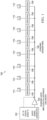
- FIG. 1 illustrates a distributed amplifier speaker system that implements one or more embodiments of a clock synchronization scheme for transmitting digital audio and power over common base-band power lines or speaker cables.
- system 100 is a multi-channel speaker system with any number, N, of speakers 110. Instead of having one amplifier and one power supply and separate dedicated cabling per speaker channel as in traditional speaker hookups, system 100 features one main amplifier and associated control unit 102, one cable run ("bus") 106, and one power supply 104 for all of the N speaker channels 110.
- bus cable run
- each speaker channel has associated with it a dedicated speaker unit 108, referred to as a "drivepack," that receives and recovers the power and audio signal that is generated by the control unit 102.
- the number N channels can be any practical number of channels dictated by the system requirements. For a standard surround sound setup, N may be 7 or 9, while for a full spatial audio (e.g., Dolby Atmos ® ) system with height speakers, N can be on the order of 16 or 24 channels or more.
- amplifier 104 is a power supply that may be implemented as a customized or standard audio amplifier to transmit a power signal over the bus 106
- control unit 102 comprises an N-channel digital audio transceiver and an audio signal generator that adds a digital audio signal onto the same bus cable.
- a digital audio transceiver of unit 102 transmits multiple digital audio streams in as driven by the power signal generated by the audio amplifier 104. These two signal streams (power and data) are transmitted simultaneously through bus 106 and are received by small electronic speaker units 108 built in (or closely coupled) to each loudspeaker 110. The speaker units 108 recover the power, receive the digital audio stream, and drive the loudspeakers with the selected signals.
- the bus cable 106 is a single standard two-conductor speaker cable of standard gauge (e.g., 10-20 gauge) and can be used to send multiple channels of digital audio and appropriate power to independent loudspeakers connected to the same two-conductor cable.
- the bus cable may be implemented as a simple two-conductor speaker cable or a three-conductor cable, such as an AC power cable where one conductor is an earth ground, or any other similar simple conductor cable.
- a solid-core Romex (typical AC wiring cable) cable might be used as well.
- portions of power source 104 may be implemented as a standard power amplifier. This may also or instead be implemented as a dedicated base-band AC or DC power source, similar to an audio amplifier but with much higher power efficiency and power throughput. For this embodiment, the system would be highly suitable for maximum power transmission, minimized power loss, and lowest cost.
- the loudspeakers 110 may represent a single driver or transducer within a single enclosure (cabinet), or a multi-driver loudspeaker with different transducers handling different audio components (e.g., woofer, midrange, tweeter), or arrays of speakers.
- the speaker units 108 can also include additional circuitry to drive each speaker component independently (e.g., woofer, tweeter, etc.) in a bi-amplification system.
- Both the control unit and each speaker unit include a transceiver stage allowing for bidirectional data flow between the digital audio transceiver of the control unit and the multiple speakers residing on the bus. Thus, other pieces of information can be propagated to-and-from the loudspeaker.
- a loudspeaker could report telemetry (e.g., down-angle, temperature, etc.), and/or setup information could be sent to individual speakers (e.g., volume control, angle adjustment for motorized pan-tilt, and so on).
- derivation of two (or more) audio signals can be done by sending the speaker unit 108 a single audio stream, wherein the speaker unit employs signal processing to derive two (or more) audio signals from a single input stream.
- the control unit 102 may also send the multiple streams directly to the individual amplification stages within the speaker unit 108.
- FIG. 2 illustrates components of control and speaker units for the distributed amplification system of FIG. 1 under some embodiments.
- the architecture of the system 200 subdivides the audio amplification process such that the power supply is physically separated from the individual output stages and is chosen such that it effectively supplies an AC stimulus to power multiple output stages.
- power source 204 comprises a standard audio amplifier to provide power for other distributed audio output stages. This helps achieve an efficiency through component reuse by eliminating one of the largest cost drivers in any audio amplifier design, i.e., the power supply.
- An audio power amplifier is typically designed as an AC-DC power supply, feeding into one or more low-impedance, transistorized, output stages. Most audio amplifiers are designed as two to four-channel devices, wherein there is a singular power supply (AC/DC offline supply) fanning out to power the output stages.
- the power supply can thus be implemented as a standard audio amplifier that develops a controlled, audio-band, AC waveform, and provide regulatory compliance (e.g., NRTL, CE, FCC, safety isolation, etc.).
- the modulating input waveform applied to the power source audio amplifier is generated by an audio signal generator in control unit 202. Because the output of the power source amplifier is used only for distributing power to the various output stages, no significant fidelity or spectral-purity requirement is imposed upon this power amplifier. Similar to the signals present on typical AC mains (120Vrms, 60Hz); the power source audio amplifiers would generate an AC waveform configured to power downstream distributed audio output stages. This allows an existing audio amplifier to serve as the power source for a distributed array of output stages, and a single cable 206 can power multiple output stages 210.
- the overall power consumption would have to be adequately determined and managed, such that the power source amplifier and cabling could adequately deliver the power as needed by the sum total of all distributed output stages connected to the line.
- the power source amp could be bridged or paralleled with a like amplifier.
- An example power supply may be a cinema-grade amplifier (e.g., Crown DSi2000) that delivers 800W per channel into 4 ohms or 1000W per channel into 2 ohms, or any similarly rated amplifier.
- the control unit 202 generates digital audio signals that comprises immersive audio having both channel-based and object-based audio components.
- an interface couples the control unit 202 to a renderer (e.g., CP850) 201, for example.
- This interface and processor provide the signal to an audio signal generator that stimulates the power source 204.
- a digital audio transmitter 203 of the control unit 202 outputs the digital audio signal directly to the output of the power source so that both power and the digital audio signal are carried on the bus cable 206.
- the control unit also includes appropriate circuitry that conditions the power and data to endure that they are properly transmitted over the bus in terms of timing, amplitude, and phase.
- the input audio may be straight digital audio, hybrid audio, pure channel-based audio, pure object-based audio, and so on.
- the system may include an integrated or separate analog-digital converter to provide the digital audio signal to stimulate the power supply 204 and provide digital audio input to the bus cable 206.
- the control unit 202 outputs digital data primarily to be coupled into the output of the power source, and input to the power source is stimulated with an analog audio-band modulation signal (i.e., sine wave, pink-noise, summed audio signal, etc.).
- an analog audio-band modulation signal i.e., sine wave, pink-noise, summed audio signal, etc.
- the system 200 can be configured to create power stimulus signals into the amplifier as well as having a line connected to the output of the amplifier to inject the digital data stream onto the speaker wire or bus cable 206.
- the digital data stream wire can also be used as a sense line for the controller through an A/D (analog/digital) circuit.
- the controller 202 can then compare the input and output signals coming from the respective amplifier channel. This allows additional features to be implemented in the software (or equivalent circuitry) such as gain modification adjustment (e.g., if the user changes the amplifier gain, the system can adjust the input signal to compensate), fault monitoring for distortion, fault monitoring for signal present, automated system configuration to alter gain structure, and other similar functions.
- the bus cable 206 that links the control unit 202 to each of the speaker units 208 is a single two-conductor speaker cable (or three-conductor power cable or similar). Data is transmitted over the bus using Internet Protocol (IP) conventions, though other protocols are also possible.
- IP Internet Protocol
- a standard power-line communication format is utilized to provide sufficient bandwidth and channel separation to allow the channelized audio information produced by the control unit to be delivered to the output stages. Examples of standard power-line communication protocol include IEEE 1901 (HomePlug AV 1.1) and the G.hn protocol. It should be noted that embodiments are not so limited, and other standardized protocols, or proprietary techniques for transmitting digital audio information over power source cabling to deliver independent audio streams to distributed output stages are also possible.
- the power signal, digital audio signal and metadata for audio object control and lighting control are transmitted over the same conductor between the control unit/amplifier and the speaker units, and are encoded in different bands of the frequency spectrum.
- the power and audio signals may be separated by frequency band.
- the power component may be relegated to a relatively low frequency band of between 0 (DC) and 20kHz, while the digital data component for the audio and lighting control may be carried in a band stretching between 1MHz to 100MHz, as an example, though embodiments are not so limited.
- FIG. 3 illustrates an example spectrum allocation for power and audio signals transmitted over the same conductors, under some embodiments.
- the spectrum allocation graph shows the amplitude (y-axis) 302 of signals versus their frequency (x-axis) 304.
- the audio band power signal is encoded in the region of 0 to 20kHz, while the digital audio transmission is encoded in the region of 1.8MHz to 86MHz.
- the separation of the power 306 and audio 308 signals is thus on the order of greater than 1.5MHz.
- FIG. 3 illustrates an example power/audio spectrum allocation and embodiments are not so limited, as any other similar spectrum allocation may also be utilized to encode audio signals for transmission over common conductors.
- FIG. 4 illustrates the distributed amplifier system of FIG. 1 as implemented using standard, commercially available components, under an example embodiment.
- audio and power signals are propagated between a source 401 and an endpoint 411 through certain electrical components per a specific sequence and over a common conductor 410. Audio signals are originated from the audio block 402 of source 401.
- the audio is then packetized into an Ethernet audio format (e.g., either AES67 or CobraNet) using an audio transmitter (e.g., Dolby CP850, Audio Science Hono 8.0L, or similar) 404.
- the packetized audio is then sent to a Power-Line Communications (PLC) transmitter 406, which is coupled to the output of a base-band power source (e.g., Crown amplifier) 408.
- PLC Power-Line Communications
- Amplifier 408 is driven by the audio signal from source 402 processed by a digital signal process (DSP) 405.
- DSP digital signal process
- the amplifier 408 then outputs a power supply signal to be conducted via a standard two-conductor loudspeaker wiring, or other similar conductor or cable 410 to the end-point electronics located at or closely coupled to the loudspeaker 420.
- the power supply signal output from the amplifier 408 and the packetized audio output from the PLC transmitter 406 are combined at the electrically coupled outputs of the PLC transmitter 406 and amplifier 408.
- a Power-Line Communication (PLC) receiver 412 is coupled to the inbound speaker wiring 410 and operable to demodulate and recover the Ethernet packets.
- the recovered Ethernet packets are then passed to an Ethernet audio receiver 416, which recovers the audio stream that originated from the original audio source 402.
- the recovered audio is then amplified using a standard or customized Class-D amplifier 418 for driving the loudspeaker transducer 420.
- Amplifier 418 also receives as an input the composite signal transmitted over conductor 410 as conditioned or converted by a Power Factor Correction (PFC) component 414.
- PFC Power Factor Correction
- FIG. 4 is provided only for the purpose of illustrating an example implementation of a distributed amplifier speaker system that includes or is modified to include a clock synchronization process.
- Such an example circuit is not intended to be limiting, and other implementations, components, configurations, and signal processing sequences are also possible.
- the PLC transmission and reception process can add latency and jitter to the packetized digital information and resulting in decoding errors within the end-point.
- the PLC latency and jitter can adversely affect the reliable recovery and synchronization of the audio clocking information that is packetized within certain AoE streams, thus leading to poor transmission of Ethernet packetized audio streams through standard PLC devices.
- certain latency and jitter added by the PLC transmission and reception process to the packetized digital information can result in decoding errors within the end-point 411.
- Embodiments thus include a clock synchronization and alignment component or system 422 that helps achieve satisfactory transmission of Ethernet packetized audio streams through standard PLC devices and common conductors (e.g., speaker wires).
- a clock synchronization and alignment component or system 422 that helps achieve satisfactory transmission of Ethernet packetized audio streams through standard PLC devices and common conductors (e.g., speaker wires).
- a distributed amplifier audio transmission and speaker playback system incorporates a clock synchronization and alignment component 422 to help achieve clock synchronization and alignment for use with packetized audio transmissions over base-band power lines or speaker cables.
- This component or processes embodied therein helps solve the issues associated with poor clock synchronization when transmitting standardized audio packets using power-line communication devices.
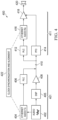
- FIG. 5 illustrates adding end-point audio clock synchronization through PLC clocking to the distributed amplifier system of FIG. 4 , under some embodiments.
- the approach of system 500 uses a hybrid combination of the two communication layers (e.g., AES67 and PLC) to provide a stable and reliable clock synchronization scheme for audio transmission over base-band power-lines.
- System 500 comprises a source circuit 401 with the audio source generating packetized Ethernet signals for transmission over conductor 410 to end-point 411 for playback through speaker 420, as described above with respect to FIG. 4 .
- the clock synchronization and alignment component 422 is embodied by clock circuit 502 for source 401and clock circuit 504 for end-point 411.
- a singular master clock 502 is employed within the main transmitter, where this master clock synchronizes the Ethernet audio transmitter 404 with the PLC modulator 406. Subsequently, the down-stream end-point 411 utilizes the PLC demodulation receiver 412 to recover and lock to the original master clock 502 and then feeds this synchronized clock to the Ethernet audio receiver 416.
- This approach thus ensures reliable clock synchronization between the master transmitter and all down-stream end-points (slaves). Due to the inherent clock synchronization requirement of modern PLC transmissions utilizing OFDM and BPSK signaling, the master clock supplied to the PLC transmitter will be recovered by the downstream PLC receiver using phase-locking methods.
- This clocking scheme also properly time aligns the clock edges to the inbound audio samples as recovered from the Ethernet data packets. This is accomplished by using the PLC telemetry information (received PLC symbol latency and jitter) to adequately adjust the recovered clock edge timing to align with the audio sample stream.
- the clocking mechanism of FIG. 5 accomplishes two goals. First, it provides clock recovery/synchronization between the source and the end-point (i.e. phase coherency is ensured between the audio source and the end-point), and second, it aligns the clock edge time with the audio sample stream. With these characteristics, reliable audio transmission can be realized using packetized audio over base-band power-line and loudspeaker cables.
- FIG. 6 is a flowchart that illustrates a method of providing end-point audio clock synchronization through PLC clocking system, such as through the system of FIG. 5 , under some embodiments.
- Process 600 begins with providing a single master clock in or with the Ethernet transmitter of the source side, 602. This master clock synchronizes the Ethernet transmitter with the PLC modulator of the source side, 604. The synchronized PLC signal is then transmitted to the end-point side over the common connector (e.g., speaker wire), 606. The PLC demodulation receiver of the end-point receives the PLC signal and recovers and locks to the original master clock, 608. This recovered original master clock signal is then provided to the Ethernet audio receiver in the end-point, 610.
- the common connector e.g., speaker wire
- the master Ethernet transmitter's clock is synchronized with the Ethernet receiver of the end-point.
- this scheme ensures that the clock is reliably synchronized between the master transmitter and all of the speaker end-points.
- the PLC signal sent from the source to the end-point is also used to properly time align the clock edges to the inbound audio samples as recovered from the Ethernet data packets.
- the transmitted synchronized PLC signal (transmitted in step 606 of flow diagram of FIG. 6 ) is also used to adequately adjust the recovered clock edge timing to align with the audio sample stream (aligned in step 612 of flow diagram of FIG. 6 ). This is done using the received PLC symbol latency and jitter (PLC telemetry data) within the received PLC signal.
- the PLC receiver can accurately adjust and align the audio sample framing to ensure robust recovery of the audio sample stream.
- audio clock synchronization between source and end-point can be accomplished through a PLC precision time protocol (PTP) update.
- PLC precision time protocol PLC precision time protocol
- the end-point Ethernet receiver adjusts and re-timestamps the PTP packetized clock information based upon the symbol timing information known within the PLC receiver.
- This technique requires the end-point PLC to have accurate timing information for its inbound symbols, similar to the previously discussed embodiment.
- FIG. 7 illustrates an end-point audio clock synchronization system using PTP updates, under some embodiments, not part of the invention .
- the approach of system 700 uses PTP packets 709 utilized by the IEEE1588 standard of the AES67 format.
- System 700 comprises a source circuit 701 with the audio source generating packetized Ethernet signals for transmission over conductor 710 to end-point 711 for playback through speaker 720, as described above with respect to FIG. 4 .
- source 701 transmits audio data in the form of PTP packets 709 to the down-stream endpoint 711.
- the PLC receiver 712 maintains certain PTP timing data 715.
- the end-point receiver 711 adjusts and re-timestamps the PTP packetized clock information 709 based upon the symbol timing information known within the PLC receiver.
- the PTP timing data comprises accurate timing information for its inbound symbols.
- the PLC receiver is configured to monitor timing of PLC encoded symbols to adjust and to re-timestamp the PTP packets.
- the end-point PLC 712 measures and provides symbol latency and symbol-to-symbol jitter performance, and then adjusts and/or re-timestamp each PTP packet to accommodate for the PLC's time varying latency and jitter aspects. Once the PTP packets are adjusted to accommodate for PLC latency and jitter, the end-point Ethernet audio receiver 716 utilizes its existing PTP clock synchronization schemes to accurately synchronize the end-point clock to that of the source Ethernet audio transmitter 704. For this embodiment, the PLC receiver 712 monitors symbol timing parameters that would be used by subsequent re-timing algorithms to correct the PTP packets as needed.
- the PLC receiver can monitor the symbol-to-symbol latency, delay, and nominal jitter performance of the physical layer (the loudspeaker cabling), the PLC receiver can pass this time skew information to the PTP algorithm, wherein the clock and audio frame recovery algorithms can be re-aligned to the transmitter.
- the clock recovery scheme uses packet-based recovery (e.g., PTP), and then adjusts the recovered clock packets to achieve alignment and synchronization, in contrast to the embodiment described above, which uses the inherent PLC clock synchronization infrastructure to achieve synchronization.
- the master clock is the primary high frequency time-base that is used to maintain phase coherency between all digital devices within the system.
- the master clock may typically operate at a frequency of 12-100MHz. In audio systems the master clock may operate at a frequency multiple of the frequency of an audio sample. For example, if the frequency of an audio sample rate is 48kHz, the master could operate at a frequency of 24.576MHz, which is 512 times the frequency of the audio sample.
- the PTP method described above can be regarded as a method of transmitting and recovering the audio sample clock over a time-variant physical layer (like Ethernet).
- the packetized data may incur varying delays as the packets move through a traditional time-variant physical layer, like Ethernet (i.e. through hubs/switches/routers).
- the PLC physical layer devices i.e. the PLC transmitter and the PLC receiver
- the PLC receiver monitors the latency and jitter of the inbound PLC encoded data (e.g. the PLC symbols being transmitted over the physical power line).
- the PLC receiver can utilize this timing information (e.g. the PLC symbol latency and jitter), to adjust the timing of the PTP packets and to re-timestamp them. This ensures that the PTP packets are properly clocked without gaps and drop outs such that an audio stream can be properly played back.
- FIG. 8 is a flowchart that illustrates a method of providing end-point audio clock synchronization through a PLC PTP update, under some embodiments not part of the invention.
- process 800 begins with the end-point receiving the PLC signal from the source side, 802.
- the end-point PLC receiver measures and provides symbol latency and symbol-to-symbol jitter performance using its internal clock recovery and symbol timing monitoring algorithms, 804.
- a down-stream algorithm then adjusts or re-timestamps each PTP packet to accommodate for the PLC's time varying latency and jitter aspects, 806.
- This algorithm would change the PTP packet time stamp to adjust for the symbol latency as measured over the nominal physical layer, and can be executed within the Ethernet audio receiver integrated circuit or programmable logic device.
- the end-point Ethernet audio receiver utilizes its existing PTP clock synchronization schemes to accurately synchronize the end-point clock to that of the master (source) transmitter, 808.
- This embodiment requires the PLC receiver in the end-point to monitor symbol timing parameters that would be used by subsequent re-timing algorithms to correct the PTP packets as needed.
- This embodiment PLC PTP update embodiment may be used in conjunction with the master clock transmission/recovery/synchronization scheme described in FIG. 6 .
- the signal received in step 802 by the end-point may be the standard audio/power signal transmitted along conductor 410, as shown in FIG. 4 , or it may be a master clocked signal as shown in FIG. 5 .
- Embodiments may be used to playback any appropriate type of audio format including stereo, surround-sound, object-based audio, or spatial (immersive) audio content.
- An example immersive audio system and associated audio format is the Dolby Atmos platform.
- Such a system incorporates a height (up/down) dimension that may be implemented as a 5.1, 7.1, 9.1 surround system, or similar surround sound configuration (e.g., 11.1, 13.1, 19.4, etc.).
- these speakers may be used to produce sound that is designed to emanate from any position more or less accurately within the listening environment.
- Immersive audio can be used in a wide variety of venues including cinemas, auditoriums, homes, and so on.
- the end-point speakers may thus be placed in any appropriate location and distance from the audio source.
- Such speakers may also be implemented in any appropriate configuration, such as single or multi-way speakers, soundbars, standing or bookcase speakers, LFE (low-frequency effect) speakers, height speakers, and so on.
- Embodiments can also be used in any appropriate power line (AC mains) infrastructure.
- AC mains power line
- the direct amplification system may enable multi-channel audio distribution through a house without burdening Wi-Fi or other wireless infrastructures. Because most powered loudspeakers require some connection to AC mains, the reliable transmission of audio could be directly realized without additional audio signal wiring.
- Embodiments of the direct amplification audio system described herein may thus be used in any appropriate venue or application, such as cinema, home cinema, live venue, auditorium, industrial facility, military facility, theme park, and so on.
Landscapes
- Engineering & Computer Science (AREA)
- Computer Networks & Wireless Communication (AREA)
- Signal Processing (AREA)
- Power Engineering (AREA)
- Details Of Audible-Bandwidth Transducers (AREA)
- Synchronisation In Digital Transmission Systems (AREA)
- Small-Scale Networks (AREA)
Claims (9)
- Verteiltes Audio-Lautsprechersystem (500), das eine Audioquelle (401) und eine Vielzahl von Endpunkten (411) umfasst, wobei jeder Endpunkt der Vielzahl von Endpunkte einen Lautsprecher (420) umfasst, der zur Wiedergabe des Audio konfiguriert ist, einen Ethernet-Empfänger (416), der mit dem Lautsprecher gekoppelt ist, und einen Powerline-Communication, PLC,-Empfänger (412), der mit dem Internet-Empfänger gekoppelt ist, aufweist, wobei die Audioquelle zum Übertragen des Audio und der Leistung über einen gemeinsamen Leiter (410) an die Vielzahl von Endpunkte konfiguriert ist, und wobei die Audioquelle Folgendes umfassteine Leistungsversorgung, die zum Erzeugen der Leistung konfiguriert ist,einen PLC-Sender (406), der mit einem Ausgang der Leistungversorgung gekoppelt ist,einen Ethernet-Audiosender (404), der mit dem PLC-Sender gekoppelt ist, und einen Haupttaktgeber (502), der mit dem PLC-Sender und dem Ethernet-Audiosender gekoppelt ist, wobei der Haupttaktgeber dazu konfiguriert ist, ein Haupttaktsignal sowohl für den Ethernet-Audiosender als auch für den PLC-Sender zu erzeugen, wobei der PLC-Sender dazu konfiguriert ist, ein PLC-codiertes Signal, das das Audio umfasst, zu erzeugen und das PLC-codierte Signal und die Leistung über den gemeinsamen Leiter zu übertragen, wobei ein Endpunkt der Vielzahl von Endpunkten dazu konfiguriert ist, das PLC-codierte Signal und den Leistung zu empfangen, wobei der PLC-Empfänger des Endpunkts dazu konfiguriert ist, das Haupttaktsignal aus dem PLC-codierten Signal zurückzugewinnen, um den Ethernet-Empfänger des Endpunkts mit dem Ethernet-Sender der Audioquelle zu synchronisieren, wobei das PLC-codierte Signal PLC-Telemetrieinformationen einschließlich PLC-Symbollatenz und Jitter umfasst, und wobei der Endpunkt dazu konfiguriert ist, das zurückgewonnene Haupttaktsignal weiter anzupassen, um es unter Verwendung der Telemetrieinformationen mit einer Audioabtaststrom des übertragenen PLC-codierten Signals abzugleichen.
- System nach Anspruch 1, wobei die Leistung ein Audioband-Leistungssignal umfasst, das in einem ersten Frequenzspektrumbereich codiert ist, und der Audioabtaststrom in einem zweiten Frequenzspektrumbereich codiert ist, der von dem ersten Frequenzspektrumbereich durch eine definierte Mindestfrequenzdifferenz getrennt ist.
- System nach Anspruch 1 oder Anspruch 2, wobei der Ethernet-Audiosender eines von einem AES67- oder CobraNet-Ethernet-Audioformat verwendet und wobei das PLC-codierte Signal eines von einem Homeplug AV2-, ITU-T-, G.HN- oder IEEE 1901-2010-Übertragungsstandard umfasst.
- System nach einem der Ansprüche 1 bis 3, wobei jeder Endpunkt der Vielzahl von Endpunkten einen dedizierten Verstärker umfasst, der eng mit einem jeweiligen Lautsprecher zur Wiedergabe von mindestens einer Audiokomponente des übertragenen Audios gekoppelt ist, und wobei der dedizierte Verstärker dazu konfiguriert ist, einen Audiokanal des übertragenen PLC-codierten Signals zu demodulieren und zu decodieren und aus der übertragenen Leistung ein Leistungssignal zurückzugewinnen, um den jeweiligen Lautsprecher zu treiben, und wobei weiter die Audioquelle über ein zweiadriges Lautsprecherkabel mit dem Endpunkt gekoppelt ist.
- System nach einem der Ansprüche 1 bis 4, das weiter eine Steuereinheit umfasst, die einen digitalen Mehrkanal-Audio-Transceiver und einen Audiosignalgenerator umfasst, der mit einem Verstärker des Klasse-D gekoppelt ist, der das Audio und Leistung an die Vielzahl von Endpunkten überträgt, und wobei das Audio mindestens eines von Stereo, Raumklang, objektbasierten oder immersiven Audioinhalt umfasst, wobei der immersive Audioinhalt sowohl objektbasierte als auch kanalbasierte Audiokomponenten umfasst.
- Verfahren zum Synchronisieren der Zeitsteuerung einer Audioquelle (401) und einer Vielzahl von Endpunkten (411), die jeweils einen Lautsprecher (420) zur Wiedergabe von Audio, einen Ethernet-Empfänger (416), der mit dem Lautsprecher gekoppelt ist, und einen Powerline-Communication, PLC,- Empfänger, (412), der mit dem Internet-Empfänger gekoppelt ist, aufweisen, wobei die Audioquelle dazu konfiguriert ist, Audio und Leistung über einen gemeinsamen Leiter (410) an die Vielzahl von Endpunkten zu übertragen, wobei die Audioquelle eine Leistungversorgung zum Erzeugen der Leistung, einen PLC-Sender (406), der mit einem Ausgang der Leistungversorgung gekoppelt ist, einen Ethernet-Audiosender (404), der mit dem PLC-Sender gekoppelt ist, und einen Haupttaktgeber (502), der mit dem PLC-Sender und dem Ethernet-Audiosender gekoppelt ist, umfasst, wobei das Verfahren Folgendes umfasst:Erzeugen der Leistung durch die Leistungsversorgung,Erzeugen eines PLC-codierten Signals, das das Audio umfasst, durch den PLC-Sender,Erzeugen eines Haupttaktsignals sowohl für den Ethernet-Audiosender als auch für den PLC-Sender durch den Haupttaktgeber;Synchronisieren des Ethernet-Audiosenders mit dem PLC-Sender unter Verwendung des Haupttaktgebersignals;Übertragen des PLC-codierten Signals und der Leistung durch den PLC-Sender an einen Endpunkt der Vielzahl von Endpunkten über den gemeinsamen Leiter;Empfangen des PLC-codierten Signals durch den PLC-Empfänger des Endpunkts;Zurückgewinnen des Haupttaktsignals aus dem PLC-codierten Signal durch den PLC-Empfänger; undBereitstellen des zurückgewonnenen Haupttaktsignals für den Ethernet-Audioempfänger des Endpunkts, um den Ethernet-Audiosender der Audioquelle mit dem Ethernet-Empfänger des Endpunkts zu synchronisieren; wobei das PLC-codierte Signal PLC-Telemetrieinformationen, einschließlich PLC-Symbollatenz und Jitter umfasst, und wobei das Verfahren weiter das Anpassen des zurückgewonnenen Haupttaktsignals in dem Endpunkt umfasst, um es mit einem Audioabtaststrom, der von der Audioquelle an die Vielzahl von Endpunkten übertragen wird, unter Verwendung der Telemetrieinformationen abzugleichen.
- Verfahren nach Anspruch 6, wobei die Leistung ein Audioband-Leistungssignal umfasst, das in einem ersten Frequenzspektrumbereich codiert ist, und der Audioabtaststrom in einem zweiten Frequenzspektrumbereich codiert ist, der von dem ersten Frequenzspektrumbereich durch eine definierte Mindestfrequenzdifferenz getrennt ist.
- Verfahren nach Anspruch 6 oder Anspruch 7, wobei der Ethernet-Audiosender eines von einem AES67- oder CobraNet-Ethernet-Audioformat verwendet, und wobei das PLC-codierte Signal eines von einem Homeplug AV2-, ITU-T-, G.HN- oder IEEE 1901-2010-Übertragungsstandard umfasst.
- Verfahren nach einem der Ansprüche 6 bis 8, wobei jeder Endpunkt der Vielzahl von Endpunkten einen dedizierten Verstärker umfasst, der eng mit einem jeweiligen Lautsprecher zur Wiedergabe von mindestens einer Audiokomponente des von der Audioquelle übertragenen Audios gekoppelt ist, und wobei der dedizierte Verstärker dazu konfiguriert ist, einen Audiokanal des übertragenen PLC-codierten Signals zu demodulieren und zu decodieren und aus der übertragenen Leistung ein Leistungssignal zurückzugewinnen, um den jeweiligen Lautsprecher zu treiben.
Applications Claiming Priority (3)
| Application Number | Priority Date | Filing Date | Title |
|---|---|---|---|
| US202063090397P | 2020-10-12 | 2020-10-12 | |
| EP20201279 | 2020-10-12 | ||
| PCT/US2021/053960 WO2022081412A2 (en) | 2020-10-12 | 2021-10-07 | Hybrid clocking scheme for transmitting packetized audio and power over a common conductor |
Publications (2)
| Publication Number | Publication Date |
|---|---|
| EP4226505A2 EP4226505A2 (de) | 2023-08-16 |
| EP4226505B1 true EP4226505B1 (de) | 2025-06-18 |
Family
ID=78333314
Family Applications (1)
| Application Number | Title | Priority Date | Filing Date |
|---|---|---|---|
| EP21798238.8A Active EP4226505B1 (de) | 2020-10-12 | 2021-10-07 | Hybrides taktschema zur übertragung von paketiertem audio und strom über einen gemeinsamen leiter |
Country Status (5)
| Country | Link |
|---|---|
| US (1) | US12592789B2 (de) |
| EP (1) | EP4226505B1 (de) |
| JP (1) | JP7829568B2 (de) |
| CN (1) | CN116349169A (de) |
| WO (1) | WO2022081412A2 (de) |
Families Citing this family (1)
| Publication number | Priority date | Publication date | Assignee | Title |
|---|---|---|---|---|
| TWI832625B (zh) * | 2022-12-21 | 2024-02-11 | 全穎科技股份有限公司 | 數位訊號編解碼方法、數位廣播系統、數位電話交換機系統 |
Family Cites Families (15)
| Publication number | Priority date | Publication date | Assignee | Title |
|---|---|---|---|---|
| WO2003042858A1 (en) | 2001-11-13 | 2003-05-22 | Enikia Llc | Media content and data distribution and consumption |
| US20050015805A1 (en) | 2003-07-17 | 2005-01-20 | Sony Corporation | Power line home network |
| US8028097B2 (en) * | 2004-10-04 | 2011-09-27 | Sony Corporation | System and method for synchronizing audio-visual devices on a power line communications (PLC) network |
| US8238376B2 (en) * | 2005-04-13 | 2012-08-07 | Sony Corporation | Synchronized audio/video decoding for network devices |
| US8539105B2 (en) | 2006-06-05 | 2013-09-17 | Stmicroelectronics, Inc. | System and method for synchronized content rendering in a multi-node network |
| US8375137B2 (en) * | 2008-07-22 | 2013-02-12 | Control4 Corporation | System and method for streaming audio using a send queue |
| CN102171750B (zh) * | 2008-10-06 | 2013-10-16 | 爱立信电话股份有限公司 | 用于输送对齐的多通道音频的方法和设备 |
| ES2851229T3 (es) | 2011-10-07 | 2021-09-03 | Audinate Holdings Pty Ltd | Sistemas, métodos y dispositivos para interconexión de redes sobre cableado de alta impedancia |
| US9806763B2 (en) * | 2012-09-10 | 2017-10-31 | Sony Corporation | Device for power line communication, power line communications system, method for operating a device for power line communication and for adapting PLC transmissions to noise |
| EP2896222A1 (de) | 2012-09-12 | 2015-07-22 | Sony Corporation | Audiosystem, tonwiedergabeverfahren, audiosignalquellenvorrichtung und tonausgabevorrichtung |
| JP6515200B2 (ja) * | 2015-04-02 | 2019-05-15 | ドルビー ラボラトリーズ ライセンシング コーポレイション | 適応型オーディオレンダリングシステムのための分散型増幅 |
| CN107925783A (zh) | 2015-09-30 | 2018-04-17 | 苹果公司 | 对媒体的同步回放和控制 |
| US10771528B2 (en) | 2016-06-29 | 2020-09-08 | Oneview Controls, Inc. | Common distribution of audio and power signals |
| US10979757B2 (en) * | 2016-07-25 | 2021-04-13 | Roku, Inc. | Synchronization with synthesized audio clock |
| WO2018071239A1 (en) | 2016-10-14 | 2018-04-19 | Thomson Licensing | Devices, systems and methods for power line endpoint identification |
-
2021
- 2021-10-07 CN CN202180069482.4A patent/CN116349169A/zh active Pending
- 2021-10-07 JP JP2023522393A patent/JP7829568B2/ja active Active
- 2021-10-07 EP EP21798238.8A patent/EP4226505B1/de active Active
- 2021-10-07 WO PCT/US2021/053960 patent/WO2022081412A2/en not_active Ceased
- 2021-10-07 US US18/248,522 patent/US12592789B2/en active Active
Also Published As
| Publication number | Publication date |
|---|---|
| JP7829568B2 (ja) | 2026-03-13 |
| WO2022081412A2 (en) | 2022-04-21 |
| US12592789B2 (en) | 2026-03-31 |
| JP2023545446A (ja) | 2023-10-30 |
| WO2022081412A3 (en) | 2022-06-16 |
| CN116349169A (zh) | 2023-06-27 |
| US20230403091A1 (en) | 2023-12-14 |
| EP4226505A2 (de) | 2023-08-16 |
Similar Documents
| Publication | Publication Date | Title |
|---|---|---|
| CN107431861B (zh) | 用于自适应音频渲染系统的分布式放大 | |
| JP5049652B2 (ja) | 通信システム、データの再生制御方法、コントローラ、コントローラの制御方法、アダプタ、アダプタの制御方法、およびプログラム | |
| US20060235552A1 (en) | Method and system for media content data distribution and consumption | |
| US9462386B2 (en) | Wired, wireless, infrared, and powerline audio entertainment systems | |
| EP2420004B1 (de) | Digital-sprechanlagen-netz über gleichspannungs- mikrofon-kabel | |
| US7346332B2 (en) | Wired, wireless, infrared, and powerline audio entertainment systems | |
| US8184662B2 (en) | Communication system, communication apparatus, and control method thereof | |
| EP2896222A1 (de) | Audiosystem, tonwiedergabeverfahren, audiosignalquellenvorrichtung und tonausgabevorrichtung | |
| EP4226505B1 (de) | Hybrides taktschema zur übertragung von paketiertem audio und strom über einen gemeinsamen leiter | |
| KR100932332B1 (ko) | 송신 장치 및 그 제어 방법 | |
| CN219269062U (zh) | 一种音频信号的发送设备、接收设备及传输系统 | |
| HK1166561B (en) | Digital intercom network over dc-powered microphone cable | |
| HK1166561A (en) | Digital intercom network over dc-powered microphone cable |
Legal Events
| Date | Code | Title | Description |
|---|---|---|---|
| STAA | Information on the status of an ep patent application or granted ep patent |
Free format text: STATUS: UNKNOWN |
|
| STAA | Information on the status of an ep patent application or granted ep patent |
Free format text: STATUS: THE INTERNATIONAL PUBLICATION HAS BEEN MADE |
|
| PUAI | Public reference made under article 153(3) epc to a published international application that has entered the european phase |
Free format text: ORIGINAL CODE: 0009012 |
|
| STAA | Information on the status of an ep patent application or granted ep patent |
Free format text: STATUS: REQUEST FOR EXAMINATION WAS MADE |
|
| 17P | Request for examination filed |
Effective date: 20230405 |
|
| AK | Designated contracting states |
Kind code of ref document: A2 Designated state(s): AL AT BE BG CH CY CZ DE DK EE ES FI FR GB GR HR HU IE IS IT LI LT LU LV MC MK MT NL NO PL PT RO RS SE SI SK SM TR |
|
| DAV | Request for validation of the european patent (deleted) | ||
| DAX | Request for extension of the european patent (deleted) | ||
| P01 | Opt-out of the competence of the unified patent court (upc) registered |
Effective date: 20240123 |
|
| GRAP | Despatch of communication of intention to grant a patent |
Free format text: ORIGINAL CODE: EPIDOSNIGR1 |
|
| STAA | Information on the status of an ep patent application or granted ep patent |
Free format text: STATUS: GRANT OF PATENT IS INTENDED |
|
| INTG | Intention to grant announced |
Effective date: 20250117 |
|
| GRAS | Grant fee paid |
Free format text: ORIGINAL CODE: EPIDOSNIGR3 |
|
| GRAA | (expected) grant |
Free format text: ORIGINAL CODE: 0009210 |
|
| STAA | Information on the status of an ep patent application or granted ep patent |
Free format text: STATUS: THE PATENT HAS BEEN GRANTED |
|
| AK | Designated contracting states |
Kind code of ref document: B1 Designated state(s): AL AT BE BG CH CY CZ DE DK EE ES FI FR GB GR HR HU IE IS IT LI LT LU LV MC MK MT NL NO PL PT RO RS SE SI SK SM TR |
|
| REG | Reference to a national code |
Ref country code: GB Ref legal event code: FG4D |
|
| REG | Reference to a national code |
Ref country code: CH Ref legal event code: EP |
|
| REG | Reference to a national code |
Ref country code: DE Ref legal event code: R096 Ref document number: 602021032532 Country of ref document: DE |
|
| REG | Reference to a national code |
Ref country code: CH Ref legal event code: EP |
|
| REG | Reference to a national code |
Ref country code: IE Ref legal event code: FG4D |
|
| PG25 | Lapsed in a contracting state [announced via postgrant information from national office to epo] |
Ref country code: FI Free format text: LAPSE BECAUSE OF FAILURE TO SUBMIT A TRANSLATION OF THE DESCRIPTION OR TO PAY THE FEE WITHIN THE PRESCRIBED TIME-LIMIT Effective date: 20250618 |
|
| REG | Reference to a national code |
Ref country code: LT Ref legal event code: MG9D |
|
| PG25 | Lapsed in a contracting state [announced via postgrant information from national office to epo] |
Ref country code: GR Free format text: LAPSE BECAUSE OF FAILURE TO SUBMIT A TRANSLATION OF THE DESCRIPTION OR TO PAY THE FEE WITHIN THE PRESCRIBED TIME-LIMIT Effective date: 20250919 Ref country code: NO Free format text: LAPSE BECAUSE OF FAILURE TO SUBMIT A TRANSLATION OF THE DESCRIPTION OR TO PAY THE FEE WITHIN THE PRESCRIBED TIME-LIMIT Effective date: 20250918 |
|
| PG25 | Lapsed in a contracting state [announced via postgrant information from national office to epo] |
Ref country code: BG Free format text: LAPSE BECAUSE OF FAILURE TO SUBMIT A TRANSLATION OF THE DESCRIPTION OR TO PAY THE FEE WITHIN THE PRESCRIBED TIME-LIMIT Effective date: 20250618 |
|
| PGFP | Annual fee paid to national office [announced via postgrant information from national office to epo] |
Ref country code: GB Payment date: 20250923 Year of fee payment: 5 |
|
| PG25 | Lapsed in a contracting state [announced via postgrant information from national office to epo] |
Ref country code: HR Free format text: LAPSE BECAUSE OF FAILURE TO SUBMIT A TRANSLATION OF THE DESCRIPTION OR TO PAY THE FEE WITHIN THE PRESCRIBED TIME-LIMIT Effective date: 20250618 |
|
| PGFP | Annual fee paid to national office [announced via postgrant information from national office to epo] |
Ref country code: FR Payment date: 20250924 Year of fee payment: 5 |
|
| PG25 | Lapsed in a contracting state [announced via postgrant information from national office to epo] |
Ref country code: RS Free format text: LAPSE BECAUSE OF FAILURE TO SUBMIT A TRANSLATION OF THE DESCRIPTION OR TO PAY THE FEE WITHIN THE PRESCRIBED TIME-LIMIT Effective date: 20250918 |
|
| REG | Reference to a national code |
Ref country code: NL Ref legal event code: MP Effective date: 20250618 |
|
| PG25 | Lapsed in a contracting state [announced via postgrant information from national office to epo] |
Ref country code: LV Free format text: LAPSE BECAUSE OF FAILURE TO SUBMIT A TRANSLATION OF THE DESCRIPTION OR TO PAY THE FEE WITHIN THE PRESCRIBED TIME-LIMIT Effective date: 20250618 |
|
| PG25 | Lapsed in a contracting state [announced via postgrant information from national office to epo] |
Ref country code: NL Free format text: LAPSE BECAUSE OF FAILURE TO SUBMIT A TRANSLATION OF THE DESCRIPTION OR TO PAY THE FEE WITHIN THE PRESCRIBED TIME-LIMIT Effective date: 20250618 |
|
| PG25 | Lapsed in a contracting state [announced via postgrant information from national office to epo] |
Ref country code: PT Free format text: LAPSE BECAUSE OF FAILURE TO SUBMIT A TRANSLATION OF THE DESCRIPTION OR TO PAY THE FEE WITHIN THE PRESCRIBED TIME-LIMIT Effective date: 20251020 |
|
| REG | Reference to a national code |
Ref country code: AT Ref legal event code: MK05 Ref document number: 1805161 Country of ref document: AT Kind code of ref document: T Effective date: 20250618 |
|
| PG25 | Lapsed in a contracting state [announced via postgrant information from national office to epo] |
Ref country code: IS Free format text: LAPSE BECAUSE OF FAILURE TO SUBMIT A TRANSLATION OF THE DESCRIPTION OR TO PAY THE FEE WITHIN THE PRESCRIBED TIME-LIMIT Effective date: 20251018 |
|
| PGFP | Annual fee paid to national office [announced via postgrant information from national office to epo] |
Ref country code: DE Payment date: 20250923 Year of fee payment: 5 |
|
| PG25 | Lapsed in a contracting state [announced via postgrant information from national office to epo] |
Ref country code: AT Free format text: LAPSE BECAUSE OF FAILURE TO SUBMIT A TRANSLATION OF THE DESCRIPTION OR TO PAY THE FEE WITHIN THE PRESCRIBED TIME-LIMIT Effective date: 20250618 Ref country code: SM Free format text: LAPSE BECAUSE OF FAILURE TO SUBMIT A TRANSLATION OF THE DESCRIPTION OR TO PAY THE FEE WITHIN THE PRESCRIBED TIME-LIMIT Effective date: 20250618 |
|
| PG25 | Lapsed in a contracting state [announced via postgrant information from national office to epo] |
Ref country code: CZ Free format text: LAPSE BECAUSE OF FAILURE TO SUBMIT A TRANSLATION OF THE DESCRIPTION OR TO PAY THE FEE WITHIN THE PRESCRIBED TIME-LIMIT Effective date: 20250618 |
|
| PG25 | Lapsed in a contracting state [announced via postgrant information from national office to epo] |
Ref country code: PL Free format text: LAPSE BECAUSE OF FAILURE TO SUBMIT A TRANSLATION OF THE DESCRIPTION OR TO PAY THE FEE WITHIN THE PRESCRIBED TIME-LIMIT Effective date: 20250618 |
|
| PG25 | Lapsed in a contracting state [announced via postgrant information from national office to epo] |
Ref country code: EE Free format text: LAPSE BECAUSE OF FAILURE TO SUBMIT A TRANSLATION OF THE DESCRIPTION OR TO PAY THE FEE WITHIN THE PRESCRIBED TIME-LIMIT Effective date: 20250618 |
|
| PG25 | Lapsed in a contracting state [announced via postgrant information from national office to epo] |
Ref country code: SK Free format text: LAPSE BECAUSE OF FAILURE TO SUBMIT A TRANSLATION OF THE DESCRIPTION OR TO PAY THE FEE WITHIN THE PRESCRIBED TIME-LIMIT Effective date: 20250618 |
|
| PG25 | Lapsed in a contracting state [announced via postgrant information from national office to epo] |
Ref country code: ES Free format text: LAPSE BECAUSE OF FAILURE TO SUBMIT A TRANSLATION OF THE DESCRIPTION OR TO PAY THE FEE WITHIN THE PRESCRIBED TIME-LIMIT Effective date: 20250618 |
|
| PG25 | Lapsed in a contracting state [announced via postgrant information from national office to epo] |
Ref country code: RO Free format text: LAPSE BECAUSE OF FAILURE TO SUBMIT A TRANSLATION OF THE DESCRIPTION OR TO PAY THE FEE WITHIN THE PRESCRIBED TIME-LIMIT Effective date: 20250618 |
|
| PG25 | Lapsed in a contracting state [announced via postgrant information from national office to epo] |
Ref country code: DK Free format text: LAPSE BECAUSE OF FAILURE TO SUBMIT A TRANSLATION OF THE DESCRIPTION OR TO PAY THE FEE WITHIN THE PRESCRIBED TIME-LIMIT Effective date: 20250618 |
|
| PG25 | Lapsed in a contracting state [announced via postgrant information from national office to epo] |
Ref country code: IT Free format text: LAPSE BECAUSE OF FAILURE TO SUBMIT A TRANSLATION OF THE DESCRIPTION OR TO PAY THE FEE WITHIN THE PRESCRIBED TIME-LIMIT Effective date: 20250618 |
|
| PLBE | No opposition filed within time limit |
Free format text: ORIGINAL CODE: 0009261 |
|
| STAA | Information on the status of an ep patent application or granted ep patent |
Free format text: STATUS: NO OPPOSITION FILED WITHIN TIME LIMIT |
|
| REG | Reference to a national code |
Ref country code: CH Ref legal event code: L10 Free format text: ST27 STATUS EVENT CODE: U-0-0-L10-L00 (AS PROVIDED BY THE NATIONAL OFFICE) Effective date: 20260430 |