EP4225664B1 - Article carriers and blanks therefor - Google Patents
Article carriers and blanks therefor Download PDFInfo
- Publication number
- EP4225664B1 EP4225664B1 EP21802509.6A EP21802509A EP4225664B1 EP 4225664 B1 EP4225664 B1 EP 4225664B1 EP 21802509 A EP21802509 A EP 21802509A EP 4225664 B1 EP4225664 B1 EP 4225664B1
- Authority
- EP
- European Patent Office
- Prior art keywords
- tabs
- article
- cut lines
- annular series
- panel
- Prior art date
- Legal status (The legal status is an assumption and is not a legal conclusion. Google has not performed a legal analysis and makes no representation as to the accuracy of the status listed.)
- Active
Links
Images


Classifications
-
- B—PERFORMING OPERATIONS; TRANSPORTING
- B65—CONVEYING; PACKING; STORING; HANDLING THIN OR FILAMENTARY MATERIAL
- B65D—CONTAINERS FOR STORAGE OR TRANSPORT OF ARTICLES OR MATERIALS, e.g. BAGS, BARRELS, BOTTLES, BOXES, CANS, CARTONS, CRATES, DRUMS, JARS, TANKS, HOPPERS, FORWARDING CONTAINERS; ACCESSORIES, CLOSURES, OR FITTINGS THEREFOR; PACKAGING ELEMENTS; PACKAGES
- B65D71/00—Bundles of articles held together by packaging elements for convenience of storage or transport, e.g. portable segregating carrier for plural receptacles such as beer cans or pop bottles; Bales of material
- B65D71/40—Bundles of articles held together by packaging elements for convenience of storage or transport, e.g. portable segregating carrier for plural receptacles such as beer cans or pop bottles; Bales of material comprising a plurality of articles held together only partially by packaging elements formed by folding a blank or several blanks
- B65D71/42—Bundles of articles held together by packaging elements for convenience of storage or transport, e.g. portable segregating carrier for plural receptacles such as beer cans or pop bottles; Bales of material comprising a plurality of articles held together only partially by packaging elements formed by folding a blank or several blanks formed by folding a single blank into a single layer element
-
- B—PERFORMING OPERATIONS; TRANSPORTING
- B65—CONVEYING; PACKING; STORING; HANDLING THIN OR FILAMENTARY MATERIAL
- B65D—CONTAINERS FOR STORAGE OR TRANSPORT OF ARTICLES OR MATERIALS, e.g. BAGS, BARRELS, BOTTLES, BOXES, CANS, CARTONS, CRATES, DRUMS, JARS, TANKS, HOPPERS, FORWARDING CONTAINERS; ACCESSORIES, CLOSURES, OR FITTINGS THEREFOR; PACKAGING ELEMENTS; PACKAGES
- B65D71/00—Bundles of articles held together by packaging elements for convenience of storage or transport, e.g. portable segregating carrier for plural receptacles such as beer cans or pop bottles; Bales of material
- B65D71/40—Bundles of articles held together by packaging elements for convenience of storage or transport, e.g. portable segregating carrier for plural receptacles such as beer cans or pop bottles; Bales of material comprising a plurality of articles held together only partially by packaging elements formed by folding a blank or several blanks
- B65D71/42—Bundles of articles held together by packaging elements for convenience of storage or transport, e.g. portable segregating carrier for plural receptacles such as beer cans or pop bottles; Bales of material comprising a plurality of articles held together only partially by packaging elements formed by folding a blank or several blanks formed by folding a single blank into a single layer element
- B65D71/44—Bundles of articles held together by packaging elements for convenience of storage or transport, e.g. portable segregating carrier for plural receptacles such as beer cans or pop bottles; Bales of material comprising a plurality of articles held together only partially by packaging elements formed by folding a blank or several blanks formed by folding a single blank into a single layer element characterised by the handle
-
- B—PERFORMING OPERATIONS; TRANSPORTING
- B65—CONVEYING; PACKING; STORING; HANDLING THIN OR FILAMENTARY MATERIAL
- B65D—CONTAINERS FOR STORAGE OR TRANSPORT OF ARTICLES OR MATERIALS, e.g. BAGS, BARRELS, BOTTLES, BOXES, CANS, CARTONS, CRATES, DRUMS, JARS, TANKS, HOPPERS, FORWARDING CONTAINERS; ACCESSORIES, CLOSURES, OR FITTINGS THEREFOR; PACKAGING ELEMENTS; PACKAGES
- B65D73/00—Packages comprising articles attached to cards, sheets or webs
- B65D73/0042—Packages comprising articles attached to cards, sheets or webs the articles being retained within a window, hole or other cut-out portion of a single card
-
- B—PERFORMING OPERATIONS; TRANSPORTING
- B65—CONVEYING; PACKING; STORING; HANDLING THIN OR FILAMENTARY MATERIAL
- B65D—CONTAINERS FOR STORAGE OR TRANSPORT OF ARTICLES OR MATERIALS, e.g. BAGS, BARRELS, BOTTLES, BOXES, CANS, CARTONS, CRATES, DRUMS, JARS, TANKS, HOPPERS, FORWARDING CONTAINERS; ACCESSORIES, CLOSURES, OR FITTINGS THEREFOR; PACKAGING ELEMENTS; PACKAGES
- B65D2571/00—Bundles of articles held together by packaging elements for convenience of storage or transport, e.g. portable segregating carrier for plural receptacles such as beer cans, pop bottles; Bales of material
- B65D2571/00123—Bundling wrappers or trays
- B65D2571/00246—Locating elements for the contents
- B65D2571/00253—Locating elements for the contents integral with the wrapper
- B65D2571/0029—Openings in top or bottom walls
-
- B—PERFORMING OPERATIONS; TRANSPORTING
- B65—CONVEYING; PACKING; STORING; HANDLING THIN OR FILAMENTARY MATERIAL
- B65D—CONTAINERS FOR STORAGE OR TRANSPORT OF ARTICLES OR MATERIALS, e.g. BAGS, BARRELS, BOTTLES, BOXES, CANS, CARTONS, CRATES, DRUMS, JARS, TANKS, HOPPERS, FORWARDING CONTAINERS; ACCESSORIES, CLOSURES, OR FITTINGS THEREFOR; PACKAGING ELEMENTS; PACKAGES
- B65D2571/00—Bundles of articles held together by packaging elements for convenience of storage or transport, e.g. portable segregating carrier for plural receptacles such as beer cans, pop bottles; Bales of material
- B65D2571/00123—Bundling wrappers or trays
- B65D2571/00432—Handles or suspending means
- B65D2571/00438—Holes
- B65D2571/00444—Holes for fingers
-
- B—PERFORMING OPERATIONS; TRANSPORTING
- B65—CONVEYING; PACKING; STORING; HANDLING THIN OR FILAMENTARY MATERIAL
- B65D—CONTAINERS FOR STORAGE OR TRANSPORT OF ARTICLES OR MATERIALS, e.g. BAGS, BARRELS, BOTTLES, BOXES, CANS, CARTONS, CRATES, DRUMS, JARS, TANKS, HOPPERS, FORWARDING CONTAINERS; ACCESSORIES, CLOSURES, OR FITTINGS THEREFOR; PACKAGING ELEMENTS; PACKAGES
- B65D2571/00—Bundles of articles held together by packaging elements for convenience of storage or transport, e.g. portable segregating carrier for plural receptacles such as beer cans, pop bottles; Bales of material
- B65D2571/00123—Bundling wrappers or trays
- B65D2571/00648—Elements used to form the wrapper
- B65D2571/00654—Blanks
- B65D2571/0066—Blanks formed from one single sheet
Definitions
- the present invention relates to article carriers and to blanks for forming the same.
- cartons for carrying multiple articles.
- Cartons are well known in the art and are useful for enabling consumers to transport, store and access a group of articles for consumption.
- such cartons or carriers need to be formed from as little material as possible and cause as little wastage in the materials from which they are formed as possible. Further considerations are the strength of the carton and its suitability for holding and transporting a weight of grouped articles. It is desirable that the contents of the carton are securely held by the carton and that the cartons or carriers are easy for a consumer to grasp and carry.
- a top engaging carrier includes a main panel which has an aperture for receiving a portion of an article.
- the main panel includes an annular series of tabs formed around the aperture. Tabs disposed in higher stress areas may be smaller in width than tabs subject to lesser stress.
- the aperture defines a first edge of each of the tabs of the annular series.
- the tabs are hingedly connected to the main panel such that they yield out of the plane of the main panel when an article is received in the aperture.
- One of the tabs of the annular series is defined at least in part by a first cutline extending from the aperture into the main panel. The first cutline separating at least a portion of the one tab from an adjacent tab.
- the main panel also includes a second cutline.
- the second cutline defines a portion of a second edge of each of the one tab and the adjacent tab, wherein the second edge opposes the first edge.
- Each second cutline is spaced apart from an end of the first cutlines so as to define a connecting portion between a pair of adjacent article tabs.
- WO 93/14993 to Kavanagh discloses a can holder of card comprises a top panel and depending side panels which form a skirt wall.
- the rims of the cans are received in apertures and held in place by resiliently deformable retaining tongues positioned at load bearing areas of the top panel.
- the skirt wall closely embraces the straight sides of the can to support the top panel and to stabilise the cans.
- the holder is erected from a blank.
- the cans are first fitted into the apertures of the blank, after which the side panels are folded downwardly and are secured to fit tightly around the cans.
- US 5,573,111 to Gordon et al discloses a bottle carrier having a central or upper panel of paperboard and at least one lower panel or layer. Each panel has a plurality of bottle neck receiving openings. The periphery of each opening of each panel is defined by the tips of a plurality of radially extending fingers, the tips of the fingers of the upper panel engaging beneath a portion of an abutment associated with each bottle neck. Each finger is bent upwardly at about 45 degrees after insertion of a bottle into a respective opening. Each upper panel radial finger is provided at its widest portion with a base slit extending through the paperboard. Another and intermediate slit is located about half way along the length of each upper panel finger, the intermediate slit also extending through the paperboard.
- the base slit permits bending of each finger upwardly upon bottle insertion, while the intermediate slit facilitates removal of each bottle from its respective opening.
- the lower panel is provided with reinforcing fingers which are in surface and reinforcing contact with the radially outermost portions only of the upper radial fingers, namely, from the base of each upper finger to its respective intermediate slit. These lower reinforcing fingers permit significant reduction in thickness of the paperboard stock which forms the carrier.
- US 2015/321817 to Spivey et al discloses a carton for holding a plurality of containers, the carton includes a top retainer having a top panel and at least one top end flap foldably connected to the top panel.
- the top panel includes at least one retaining portion having at least one receptacle for retaining at least one container of the plurality of containers, and the at least one retaining portion is removable from the carton.
- the carton further includes a tray having a bottom panel and at least one bottom end flap foldably connected to the bottom panel. The at least one top end flap and the at least one bottom end flap cooperate to form a closed end of the carton.
- the present invention seeks to provide an improvement in the field of cartons, typically formed from paperboard or the like.
- a first aspect of the invention provides an article carrier for packaging at least one article.
- the article carrier comprises at least one panel having at least one article engaging structure.
- the at least one article engaging structure comprises an article receiving aperture and an annular series of tabs formed around the article receiving aperture.
- the annular series of tabs is defined at least in part by a plurality of radial cut lines.
- the annular series of tabs is also defined at least in part by a plurality of circumferential cut lines. At least a first one of the radial cut lines extends to a corresponding circumferential cut line and at least a second one of the radial cut lines stops short of a respective circumferential cut line.
- deformation of a corner region of the main panel is reduced by providing at least one T-shaped cut in the article receiving structure.
- the T-shaped cut is provided in the corner region.
- the at least one article receiving aperture is a corner aperture
- the at least first one of the radial cut lines is positioned across from the respective corner of the at least one panel such that the at least first one of the radial cut lines extends from the corner aperture toward the corner.
- the at least one article receiving aperture is a corner aperture, and at least two of the annular series of tabs are separated by a tabless area, the at least first one of the radial cut lines defines part of at least one of the at least two of the annular series of tabs.
- the tabless area is positioned across from the respective corner of the at least one panel.
- the at least first one of the radial cut lines defines part of each of at least two of the annular series of tabs, at least one of the at least two of the annular series of tabs has a width dimension which is less than a width dimension of at least another one of the annular series of tabs.
- a second aspect of the invention provides an article carrier for packaging at least one article.
- the article carrier comprises at least one panel having at least one article engaging structure.
- the at least one article engaging structure comprises an article receiving aperture and an annular series of tabs formed around the article receiving aperture.
- the annular series of tabs comprises a plurality of annularly connected tabs and a plurality of annularly disconnected tabs.
- the annularly disconnected tabs are partial tabs, wherein each annularly disconnected tab occupies a smaller portion of the circumference of the at least one article engaging structure than a portion of the circumference of the at least one article engaging structure occupied by one of the annularly connected tabs.
- an engaging edge of a first one of the partial tabs is collinear with an engaging edge of a second adjacent one of the partial tabs.
- each partial tab of a pair comprises an engaging edge arranged collinearly with an engaging edge of the other one of the pair.
- the partial tabs are dimensioned such that an integer number of partial tabs is equivalent to an integer number of annularly connected tabs.
- the annular series of tabs is interrupted by a cutaway, the cutaway occupies a portion of the circumference of the at least one article engaging structure disposed in closest proximity to a point of intersection between a first notional line collinear with an end edge of the at least one panel and a second notional line collinear with a side edge of the at least one panel.
- the point of intersection is a notional corner of the at least one panel.
- the cutaway is a T-shaped cut line.
- the cutaway interrupts the annularly disconnected tabs.
- the annularly disconnected tabs define a sector of the at least one article engaging structure disposed adjacent to a corner of the at least one panel.
- the annularly disconnected tabs define a sector of the at least one article engaging structure disposed proximate to a corner of the at least one panel.
- a third aspect of the invention provides a blank for forming an article carrier.
- the blank comprises at least one panel having at least one article engaging structure.
- the at least one article engaging structure comprises an article receiving aperture and an annular series of tabs formed around the article receiving aperture.
- the annular series of tabs is defined at least in part by a plurality of radial cut lines.
- the annular series of tabs is also defined at least in part by a plurality of circumferential cut lines. At least a first one of the radial cut lines extends to a corresponding circumferential cut line and at least a second one of the radial cut lines stops short of a respective circumferential cut line.
- a fourth aspect of the invention provides a blank for forming an article carrier.
- the blank comprises at least one panel having at least one article engaging structure.
- the at least one article engaging structure comprises an article receiving aperture and an annular series of tabs formed around the article receiving aperture.
- the annular series of tabs comprises a plurality of annularly connected tabs and a plurality of annularly disconnected tabs.
- the annularly disconnected tabs are partial tabs, that is, each occupies a smaller portion of the circumference of the at least one article engaging structure than a portion of the circumference of the at least one article engaging structure occupied by one of the annularly connected tabs.
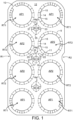
- FIG. 1 there is shown a plan view of a blank 10 which is capable of forming a carton or carrier 90, as shown in Figure 2 .
- the carrier 90 is suitable for containing and carrying a group of primary products such as, but not limited to, bottles or cans, hereinafter referred to as articles B.
- the blank 10 forms a secondary package 90 that packages at least one primary product container B.
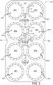
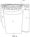
- An alternative blank 110 is shown in Figure 3 for forming an alternative carton or carrier 190 shown in Figure 4 .
- the terms “carton” and “carrier” refer, for the non-limiting purpose of illustrating the various features of the invention, to a container for engaging and carrying articles, such as primary product containers (articles B). It is contemplated that the teachings of the invention can be applied to various product containers, which may or may not be tapered and/or cylindrical. Exemplary containers may include bottles (for example metallic, glass or plastics bottles), cans (for example aluminum cans), tins, pouches, packets and the like.
- the packaging structures or cartons 90; 190, described herein, may be formed from a sheet material such as paperboard, which may be made of or coated with materials to increase its strength.
- a sheet material such as paperboard
- An example of such a sheet material is tear-resistant NATRALOCK ® paperboard made by WestRock Company.
- the tear resistant materials may be provided by more than one layer, to help improve the tear-resistance of the package.
- one surface of the sheet material may have different characteristics to the other surface.
- the surface of the sheet material that faces outwardly from a finished package may be particularly smooth and may have a coating such as a clay coating or other surface treatment to provide good printability.
- the surface of the sheet material that faces inwardly may, on the other hand, be provided with a coating, a layer, a treatment or be otherwise prepared to provide properties such as one or more of tear-resistance, good glue-ability, heat sealability, or other desired functional properties.
- the blanks 10; 110 are configured to form a carton or carrier 90; 190 for packaging an exemplary arrangement of exemplary articles B.
- the arrangement is a 4 x 2 matrix or array.
- four rows of two articles are provided, and the articles B are beverage cans.
- the blanks 10; 110 can be configured to form a carrier for packaging other types, number and size of articles and/or for packaging articles in a different arrangement or configuration.
- Figure 1 illustrates a first embodiment and shows the blank 10 for forming the article carrier 90 shown in Figure 2 .
- the carrier 90 takes the form of a top gripping clip.
- the article carrier 90 comprises openings configured to receive the articles B. The openings are arranged to accommodate a neck or upper portion of an article B, above a main body and/or shoulders of the article B.
- the blank 10 comprises a main or engaging panel 12.
- the main panel 12 of the blank 10 includes at least one article retention structure RT1, RT2.
- the main panel 12 comprises a plurality of article retention structures RT1, RT2, specifically eight article retention structures RT1, RT2 arranged in 2 x 4 matrix or array.
- Each of the article retention structures RT1, RT2 comprises an article receiving aperture AP1, AP2 about which a plurality of teeth or tabs 14, 30 may be disposed.
- Each of the teeth 14, 30 is struck from the engaging panel 12 and is hingedly connected thereto.
- Each tooth 14, 30 may be defined, in part, by a pair of cut lines 15, 31.
- the cut lines 15, 31 extend radially outward from a centre of the article receiving aperture AP1, AP2.
- the teeth or tabs 14, 30 are arranged in an annular series about the article receiving aperture AP1, AP2 to form part of an article receiving opening.
- the plurality of teeth 14, 30 are provided by the main panel 12. Each of the teeth 14, 30 is hingedly connected to the main panel 12, by a hinged connection.
- the hinged connection may be defined by a plurality of cut lines 9, 11.
- the plurality of cut lines 9, 11 may be arranged as an annular series of cuts about the article receiving aperture AP1, AP2.
- the plurality of cut lines 9, 11 may define or approximate a portion of circle.
- the blank 10 comprises four endmost article retention structures RT1 each comprising a first article receiving aperture AP1.
- the blank 10 comprises four medial or intermediate article retention structures RT2 each comprising a second article receiving aperture AP2.
- the endmost article retention structures RT1 comprise an article receiving opening defined in part by the first article receiving aperture AP1 which is defined in, or struck from, the main panel 12.
- the intermediate article retention structures RT2 comprise an article receiving opening defined in part by the second article receiving aperture AP2 which is defined in, or struck from, the main panel 12.
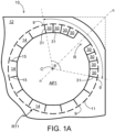
- the endmost article retention structures RT1 comprise a first plurality of teeth or tabs 14, 30 disposed about the first article receiving aperture AP1, best shown in Figure 1A .
- Each of the first plurality of teeth 14, 30 comprises an engaging edge opposing a hinged edge.
- the engaging edges are defined by a linear portion of a cut line defining the first article receiving aperture AP1.
- Each engaging edge may define a part of a polygon.
- the illustrated embodiment comprises nineteen teeth 14, 30 together defining a substantial portion of hexadecagon.
- the endmost article retention structures RT1 comprise eleven full teeth 14 and eight half or partial teeth 30.
- the partial teeth 30 occupy a smaller circumferential region of the article receiving opening than the full teeth 14.
- Each full tooth 14 comprises a pair of side edges, the side edges are defined by cuts 15 extending radially outward from respective vertices of the hexadecagon forming the first article receiving aperture AP1, that is to say, from a respective vertex between a pair of adjacent linear portions of the cut defining the portion of a hexadecagon.
- the cuts 15 are divergently arranged with respect to each other and define an angle therebetween, the angle may be about 22.5°.
- Each partial tooth 30 comprises a pair of side edges, the side edges are defined by cuts 31 extending radially outward from the first article receiving aperture AP1.
- the cuts 31 are divergently arranged with respect to each other and define an angle therebetween, the angle may be about 11.25°.
- Adjacently disposed pairs of the partial teeth 30 define a linear portion of the cut defining the portion of a hexadecagon, that is to say the engaging edges of each of the pairs of partial teeth 30 are collinear.
- the endmost article retention structures RT1 comprise a plurality of first circumferential cut lines 9.
- Each of the plurality of first circumferential cut lines 9 is aligned with one of the radial cut lines 15, 31 such that said one of the radial cut lines 15, 31 or a notional extension thereof bisects a respective one of the plurality of first circumferential cut lines 9.
- Each of the radial cut lines 15 defining a full tooth 14 is spaced apart from a corresponding one of the plurality of first circumferential cut lines 9.
- Each radial cut line 15 is arranged with respect to one of the plurality of first circumferential cut lines 9 so as to bisect first circumferential cut lines 9. In this way a connecting nick or bridge portion is provided between a pair of adjacently disposed full teeth 14.
- the radial cut lines 15 and first circumferential cut lines 9 define disconnected T-shaped cuts.
- Each of the radial cut lines 31 defining a partial tooth 30 is connected to, or contiguous with, a corresponding one of the plurality of first circumferential cut lines 9.
- Each radial cut line 31 is arranged with respect to one of the plurality of first circumferential cut lines 9 so as to bisect first circumferential cut lines 9. In this way each partial tooth 30 is disconnected from the adjacently disposed teeth 14, 30.
- the radial cut lines 31 and first circumferential cut lines 9 define connected T-shaped cuts.
- Each of the plurality of first circumferential cut lines 9 may be linear in shape.
- the endmost article retention structures RT1 comprise a plurality of second circumferential cut lines 11.
- Each of the plurality of second circumferential cut lines 11 is disposed between a pair of the plurality of first circumferential cut lines 9 and is spaced apart therefrom so as to define a pair of connecting nick or bridge portions between each full tooth 14 and the main panel 12.
- the pair of connecting nick or bridge portions provide a hinged or foldable connection between each full tooth 14 and the main panel 12.
- Each of the plurality of second circumferential cut lines 11 may be linear in shape.
- the partial teeth 30 are connected to the main panel 12 by a hinged or foldable connection between formed by a connecting nick or bridge portion provided between an adjacent pair of the plurality of first circumferential cut lines 9.
- each of the plurality of first circumferential cut lines 9 may be arcuate or curved.
- each of the plurality of second circumferential cut lines 11 may be arcuate or curved.
- the plurality of teeth 14, 30 is interrupted by a first recess or cutaway R.
- the first recess R lies upon a first notional line n-n.
- First notional line n-n extends radially from the centre C of the apertures AP1 and passes through a notional corner of the main panel 12.
- the first recess R may be dimensioned to be equivalent to a pair of partial teeth 30, and is centered upon the first notional line n-n.
- the first recess R may be replaced with a pair of partial teeth 30 separated by a radial cut line 31 lying upon the first notional line n-n, to form a connected T-cut with a first circumferential cut line 9.
- the partial teeth 30 and first recess R define a first or minor arc.
- the full teeth extend about or occupy a second or major arc.
- the minor arc defines a sector which subtends a first angle ⁇ .
- the first angle ⁇ may be about 112.5° or equivalent to five full teeth 14 or ten partial teeth 30.
- the intermediate article retention structures RT2 comprise a second plurality of teeth or tabs 14 disposed about the second article receiving aperture AP2.
- Each of the second plurality of teeth 14 comprises an engaging edge opposing a hinged edge.
- the engaging edges are defined by a linear portion of a cut line defining the second article receiving aperture AP2.
- Each engaging edge may define a part of a polygon.
- the illustrated embodiment comprises sixteen full teeth 14 together defining a hexadecagon.
- Each full tooth 14 comprises a pair of side edges, the side edges are defined by cuts 15 extending radially outward from respective vertices of the hexadecagon forming the second article receiving aperture AP2, that is to say, from a respective vertex between a pair of adjacent linear portions of the cut defining the portion of a hexadecagon.
- the cuts 15 are divergently arranged with respect to each other and define an angle therebetween, the angle may be about 22.5°.
- the intermediate article retention structures RT2 comprise a plurality of first circumferential cut lines 9.
- Each of the plurality of first circumferential cut lines 9 is aligned with one of the radial cut lines 15 such that said one of the radial cut lines 15 or a notional extension thereof bisects a respective one of the plurality of first circumferential cut lines 9.
- Each of the radial cut lines 15 defining a full tooth 14 is spaced apart from a corresponding one of the plurality of first circumferential cut lines 9. In this way a connecting nick or bridge portion is provided between pairs of adjacently disposed full teeth 14.
- the radial cut lines 15 and first circumferential cut lines 9 define disconnected T-shaped cuts.
- the intermediate article retention structures RT2 comprise a plurality of second circumferential cut lines 11.
- Each of the plurality of second circumferential cut lines 11 is disposed between a pair of the plurality of first circumferential cut lines 9 and is spaced apart therefrom so as to define a pair of connecting nick or bridge portions between each full tooth 14 and the main panel 12.
- the pair of connecting nick or bridge portions provide a hinged or foldable connection between each full tooth 14 and the main panel 12.
- the blank 10 may comprise a handle structure.
- the handle structure comprises one, two, three or more handle or finger openings spaced apart from each other.
- the handle or finger openings are disposed on a longitudinal axis bisecting the engaging panel 12.
- a first opening Ha1 is provided between a first group of four article retention structures RT1, RT2.
- the first group of four article retention structures RT1, RT2 is provided adjacent a first end of the engaging panel 12.
- the first opening Ha1 is disposed between a first row of endmost article retention structures RT1 and a second row of intermediate article retention structures RT2.
- the first opening Ha1 is located at the centre of the first group of four article retention structures RT1, RT2.
- a second opening Ha2 is provided between a second group of four article retention structures RT2.
- the second group of four article retention structures RT2 is provided medially of the engaging panel 12.
- the second opening Ha2 is disposed between the second row of intermediate article retention structures RT2 and a third row of intermediate article retention structures RT2.
- the second opening Ha2 is located at the centre C of the second group of four article retention structures RT2.
- a third opening Ha3 is provided between a third group of four article retention structures RT1, RT2.
- the third group of four article retention structures RT1, RT2 is provided adjacent a second end of the engaging panel 12.
- the third opening Ha3 is disposed between the third row of intermediate article retention structures RT2 and a fourth row of endmost article retention structures RT1.
- the third opening Ha3 is located at the centre of the third group of four article retention structures RT1, RT2.
- the first, second and third openings Ha1, Ha2, Ha3 lie, at least in part, between a first column of article retention structures RT1, RT2 and a second column of article retention structures RT1, RT2.
- Each of the handle openings Ha1, Ha2, Ha3 is defined by a plurality of tabs 16, 18, 20, 22.
- the first and second handle openings Ha1, Ha2 are substantially similar in construction to each other.
- the third handle opening Ha3 is substantially similar in construction to the first and second handle openings Ha1, Ha2 albeit a mirror image thereof.
- the handle openings Ha1, Ha2, Ha3 will be described in further detail by reference to the second handle opening Ha2 shown in Figure 1A .
- Each handle opening Ha1, Ha2, Ha3 comprises four tabs 16, 18, 20, 22.
- Each tab 16, 18, 20, 22 is hinged to the engaging panel 12 by a hinged connection in the form of a fold line 17, 19, 21, 23.
- An arcuate or curvilinear cut line 31, 33, 35, 37 may be provided between each fold line 17, 19, 21, 23 to define a corner or vertex of the handle openings Ha1, Ha2, Ha3.
- Each of the handle openings Ha1, Ha2, Ha3 is substantially rhombus or diamond shaped, in other embodiments other shapes may be employed such as, but not limited to square.
- Each handle opening Ha1, Ha2, Ha3 comprises a pair of major tabs 16, 18 and a pair of minor tabs 20, 22.
- a first major tab 16 is separated from a second major tab 18 by a first cut line or severable line 25.
- a first minor tab 20 is separated from a second minor tab 22 by the first cut line or severable line 25.
- the first and second minor tabs 20, 22 are separated from the first and second major tabs 16, 18 by a second cut line or severable line 27.
- the first cut line 25 is colinear with a notional line passing though the centre C of the group of four intermediate article retention structures RT2.
- the first cut line 25 may be linear in shape and may extend between a first pair of opposed vertices of the handle opening Ha1, Ha2, Ha3.
- the second cut line 27 may be non-linear in shape and may extend between a second pair of opposed vertices of the handle opening Ha1, Ha2, Ha3.
- the second cut line 27 intersects the first cutline 25, the second cut line 27 comprises an inverted "V" shaped medial portion; a vertex of the "V" shaped portion intersects the first cutline 25.
- the first major tab 16 is hinged to the engaging panel 12 by a first fold line 17.
- the second major tab 18 is hinged to the engaging panel 12 by a second fold line 19.
- the first minor tab 20 is hinged to the engaging panel 12 by a third fold line 21.
- the second minor tab 22 is hinged to the engaging panel 12 by a fourth fold line 23.
- the first fold line 17 is divergently arranged with respect to the second fold line 19.
- the first fold line 17 is divergently arranged with respect to the third fold line 21.
- the second fold line 19 is divergently arranged with respect to the fourth fold line 23.
- the third fold line 21 is divergently arranged with respect to the fourth fold line 23.
- the blank 10 comprises a first recess or cutaway R1 struck from a first side edge (see Figure 1 ).
- the first finger recess or cutaway R1 lies upon a notional line extending laterally of the blank 10 and bisecting the blank 10. In this way the first finger recess or cutaway R1 lies between the second and third rows of article retention structures RT1.
- the blank 10 comprises a second finger recess or cutaway R2 struck from a second side edge.
- the second side edge opposes the first side edge.
- the second finger recess or cutaway R2 lies upon a notional line extending laterally of the blank 10 and bisecting the blank 10. In this way the second finger recess or cutaway R2 lies between the second and third rows of article retention structures RT1.
- the second handle opening Ha2 is collinear with the first and second finger recesses R1, R2.
- the blank 10 forms a carrier 90, the blank 10 is lowered with respect to a group of articles B.
- Each opening of the retention structures RT1, RT2 receives one of the articles B forming the group.
- An end closure or upper end of the articles B passes through the openings.
- the tabs 14, 30 fold out of the plane of the engaging panel 12.
- the tabs 14, 30 fold upwardly, the tabs 14, 30 engage an article B below a flange or projection extending radially outward from the neck of the article B.
- the tabs 14, 30 support the article B and inhibit movement or withdrawal of the article B from the opening, best shown in Figure 2 .
- the first recess R has the benefit of reducing deformation of a corner region 12C of the main panel 12.
- the connected T-cuts provided by the radial cut lines 31 and first circumferential cut lines 9 reduce stress in the corner region 12C of the main panel 12.
- the absence of connecting portions between the partial teeth 30 has been found to reduce the likelihood of tear propagation in the main panel 12.
- the connecting nicks between full teeth 14 may increase the security of the article B within the article receiving structure RT1, and may increase biasing of the tabs 14 against the article B so as to improve article retention.
- Figure 3 illustrates a second embodiment and shows a blank 110 for forming an article carrier 190 shown in Figure 4 .
- the blank 110 comprises an engaging panel 112.
- the engaging panel 112 of the blank 110 includes at least one article retention structure RT1, RT2, each retention structure RT1, RT2 provides an article receiving aperture AP1, AP2 for receiving a respective article.
- the engaging panel 112 comprises a plurality of article retention structures RT1, RT2, specifically eight article retention structures RT1, RT2 arranged in 2 x 4 matrix or array.
- Each of the article retention structures RT1, RT2 comprises an opening or aperture AP1, AP2 about which a plurality of teeth or tabs 114 may be disposed.
- Each of the teeth 114 is struck from the engaging panel 112 and is hingedly connected thereto.
- Each tooth 114 may be defined, in part, by a pair of cut lines 115.
- the cut lines 115 extend radially outward from a centre of the article receiving aperture AP1, AP2.
- the teeth or tabs 114 are arranged in an annular series about the article receiving aperture AP1, AP2 to form part
- the plurality of teeth 114 are provided by the engaging panel 112. Each of the teeth 114 is hingedly connected to the engaging panel 112, by a hinged connection.
- the hinged connection may be defined by a plurality of cut lines 109, 111.
- the plurality of cut lines 109, 111 may be arranged as an annular series of cuts about the article receiving aperture AP1, AP2.
- the plurality of cut lines 109, 111 may define or approximate a portion of circle.
- the blank 110 comprises four endmost article retention structures RT1 each comprising a first article receiving aperture AP1.
- the blank 110 comprises four medial or intermediate article retention structures RT2 each comprising a second article receiving aperture AP2.
- the endmost article retention structures RT1 comprise an article receiving opening defined in part by the first article receiving aperture AP1 which is defined in, or struck from, the engaging panel 112.
- the endmost article retention structures RT1 comprise a first plurality of teeth or tabs 114 disposed about the first article receiving aperture AP1, best shown in Figure 3A .
- Each of the first plurality of teeth 114 comprises an engaging edge opposing a hinged edge.
- the engaging edges are defined by a linear portion of a cut line defining the first article receiving aperture AP1.
- Each engaging edge may define a part of a polygon.
- the illustrated embodiment comprises sixteen teeth 114 together defining a hexadecagon.
- Each tooth 114 comprises a pair of side edges, the side edges are defined by cuts 115, 131 extending radially outward from respective vertices of the hexadecagon forming the first article receiving aperture AP1, that is to say, from a respective vertex between a pair of adjacent linear portions of the cut defining the portion of a hexadecagon.
- the cuts 115, 131 are divergently arranged with respect to each other and define an angle therebetween, the angle may be about 22.5°.
- the endmost article retention structures RT1 comprise a plurality of first circumferential cut lines 109. Each of the plurality of first circumferential cut lines 109 is aligned with one of the radial cut lines 115, 131.
- the endmost article retention structures RT1 comprise first radial cut lines 115 and second radial cut lines 131. Each of the second radial cut lines 131 is connected to, or contiguous with, a corresponding one of the plurality of first circumferential cut lines 109.
- Each of the second radial cut lines 131 bisects and intersects with a respective one of the plurality of first circumferential cut lines 109.
- a notional extension of each of the first radial cut lines 115 bisects a respective one of the plurality of first circumferential cut lines 109.
- the endmost article retention structures RT1 comprise five second radial cut lines 131 each defining at least in part one of four annularly disconnected teeth or tabs 114A.
- Each of the first radial cut lines 115 is spaced apart from a corresponding one of the plurality of first circumferential cut lines 109. In this way a connecting nick or bridge portion is provided between a pair of adjacently disposed full teeth 114.
- the first radial cut lines 115 and respective first circumferential cut lines 109 define disconnected T-shaped cuts.
- the endmost article retention structures RT1 comprise eleven first radial cut lines 115 each defining at least in part one of twelve annularly connected teeth 114.
- the second radial cut lines 131 and respective first circumferential cut lines 109 define connected T-shaped cuts.
- Each of the plurality of first circumferential cut lines 109 may be linear or arcuate in shape.
- the endmost article retention structures RT1 comprise a plurality of second circumferential cut lines 111.
- Each of the plurality of second circumferential cut lines 111 is disposed between a pair of the plurality of first circumferential cut lines 109 and is spaced apart therefrom so as to define a pair of connecting nick or bridge portions between each full tooth 114 and the engaging panel 112.
- the pair of connecting nick or bridge portions provide a hinged or foldable connection between each full tooth 114 and the engaging panel 112.
- Each of the plurality of second circumferential cut lines 111 may be linear or arcuate in shape.
- the first recess or cutaway R of the embodiment of Figure 1 has been omitted, the first article receiving aperture AP1 is surrounded by teeth 114, 114A.
- the arrangement of teeth 114, 114A, the cut pattern of radial cut lines 115, 131, has been rotated about the centre of the first article receiving aperture AP1 with respect to the arrangement of teeth 114, the cut pattern of radial cut lines 115, about the second article receiving aperture AP2 of the intermediate article retention structures RT2, best illustrated in Figure 3A .
- the endmost article retention structures RT1 are rotated through an angle ⁇ with respect to intermediate article retention structures RT2.
- the angle of rotation ⁇ may be about 11.25° or equivalent to half a tooth 114.
- One of the second radial cut lines 131 lies upon a notional line n-n passing through the centre C of the first article receiving aperture AP1 and through a real, or notional, corner of the engaging panel 112 - the real or notional corner being defined by the intersection of a pair of notional lines collinear with a respective one of the end and side edges of the main panel 112.
- the endmost article retention structures RT1 comprises a first second radial cut line 131 which lies upon a notional line y-y extending longitudinally of the blank 110; said first second radial cut line 131 is oriented perpendicular with respect to an end edge of the engaging panel 112 and is parallel to a longitudinal axis of the engaging panel 112.
- the endmost article retention structures RT1 comprises a second second radial cut line 131 which lies upon a notional line x-x extending transversely of the blank 110; said second second radial cut line 131 is oriented perpendicular with respect to a side edge of the engaging panel 112 and is perpendicular to the longitudinal axis of the engaging panel 112.
- the endmost article retention structures RT1 comprises a first radial cut line 115 which lies upon the notional line y-y extending longitudinally of the blank 110; said first radial cut line 115 lies upon a notional radial line extending from the centre of the second article receiving aperture AP2 of the adjacent intermediate article retention structures RT2.
- the notional radial line extends through the centre or middle of one of the teeth 114 surrounding the second article receiving aperture AP2.
- the annularly disconnected teeth 114A define a first or minor arc.
- the annularly connected teeth 114 extend about or occupy a second or major arc.
- the minor arc defines a sector which subtends a first angle ⁇ .
- the first angle ⁇ may be about 90° or equivalent to four teeth 114A.
- the intermediate article retention structures RT2 comprise a second plurality of teeth or tabs 114 disposed about the second article receiving aperture AP2.
- Each of the second plurality of teeth 114 comprises an engaging edge opposing a hinged edge.
- the engaging edges are defined by a linear portion of a cut line defining the second article receiving aperture AP2.
- Each engaging edge may define a part of a polygon.
- the illustrated embodiment comprises sixteen teeth 114 together defining a hexadecagon.
- Each tooth 114 comprises a pair of side edges, the side edges are defined by cuts 115 extending radially outward from respective vertices of the hexadecagon forming the second article receiving aperture AP2, that is to say, from a respective vertex between a pair of adjacent linear portions of the cut defining the portion of a hexadecagon.
- the cuts 115 are divergently arranged with respect to each other and define an angle therebetween, the angle may be about 22.5°.
- the intermediate article retention structures RT2 comprise a plurality of first circumferential cut lines 109.
- Each of the plurality of first circumferential cut lines 109 is aligned with one of the radial cut lines 115 such that said one of the radial cut lines 115 or a notional extension thereof bisects a respective one of the plurality of first circumferential cut lines 109.
- Each of the radial cut lines 115 defining a tooth 114 is spaced apart from a corresponding one of the plurality of first circumferential cut lines 109. In this way a connecting nick or bridge portion is provided between pairs of adjacently disposed full teeth 114.
- the radial cut lines 115 and first circumferential cut lines 109 define disconnected T-shaped cuts.
- the intermediate article retention structures RT2 comprise a plurality of second circumferential cut lines 111.
- Each of the plurality of second circumferential cut lines 111 is disposed between a pair of the plurality of first circumferential cut lines 109 and is spaced apart therefrom so as to define a pair of connecting nick or bridge portions between each full tooth 114 and the engaging panel 112.
- the pair of connecting nick or bridge portions provide a hinged or foldable connection between each full tooth 114 and the engaging panel 112.
- the present disclosure provides a carrier 90; 190, and a blank 10; 110 for forming the carrier 90; 190, having a main panel 12; 112 with openings for receiving at least one article B.
- the main panel 12; 112 may comprise a handle structure.
- the present disclosure provides a blank 10; 110 for forming an article carrier 90; 190 of the top engaging type.
- the blank 10; 110 or article carrier 90; 190 comprises at least one panel 12; 112 having at least one article engaging structure RT1, RT2.
- the at least one article engaging structure RT1, RT2 comprises an article receiving aperture AP1, AP2 and an annular series of tabs 14, 30; 114, 114A formed around the article receiving aperture AP1, AP2.
- the annular series of tabs 14, 30; 114, 114A is defined at least in part by plurality of radial cut lines 15, 31; 115, 131.
- the annular series of tabs 14, 30; 114, 114A is defined at least in part by plurality of circumferential cut lines 9, 11; 109, 111. At least a first one 31, 131 of the radial cut lines extends to a corresponding circumferential cut line 9, 109 and at least a second one 15; 115 of the radial cut lines stops short of a respective circumferential cut line 9, 109.
- the at least one article receiving aperture AP1 may be a corner aperture, and the at least first one of the radial cut lines 131 may be positioned across from the respective corner of the at least one panel 12; 112 such that the at least first one of the radial cut lines 131 extends from the corner aperture toward the corner.
- the at least one article receiving aperture AP1 may be a corner aperture, and at least two of the annular series of tabs 30 may be separated by a toothless or tabless area or recess R.
- the at least first one 31 of the radial cut lines may define part of at least one of the at least two of the annular series of tabs 30.
- the tabless area or recess R may be positioned across from the respective corner of the at least one panel 12; 112.
- the at least two of the annular series of tabs 30 each may have a width dimension which is less than a width dimension of at least another one of the annular series of tabs 14.
- the at least first one of the radial cut lines 31 may define part of each of at least two of the annular series of tabs 30, at least one of the at least two of the annular series of tabs 30 may have a width dimension which is less than a width dimension of at least another one of the annular series of tabs 14.
- the present disclosure provides a blank 10; 110 for forming an article carrier 90; 190 of the top engaging type.
- the blank 10; 110 or article carrier 90; 190 comprises at least one panel 12; 112 having at least one article engaging structure RT1, RT2.
- the at least one article engaging structure RT1, RT2 comprises an article receiving aperture AP1, AP2 and an annular series of tabs 14, 30; 114, 114A formed around the article receiving aperture AP1, AP2.
- the annular series of tabs 14, 30; 114, 114A comprises a plurality of annularly connected tabs 14; 114 and a plurality of annularly disconnected tabs 30; 114A.
- the annularly disconnected tabs 30 are partial or half tabs 30, that is to say each annularly disconnected tab 30 occupies a smaller portion of the circumference of the at least one article engaging structure RT1 than a portion of the circumference of the at least one article engaging structure RT1 occupied by one of the annularly connected tabs 14; 114.
- an engaging edge of a first one of the partial or half tabs 30 is colinear with an engaging edge of a second adjacent one of the partial or half tabs 30.
- the partial or half tabs 30 are arranged in pairs, each partial or half tab 30 of a pair comprising an engaging edge arranged collinearly with an engaging edge of the other one of the pair.
- the partial tabs 30 may be dimensioned such that an integer number of partial tabs 30 is equivalent to an integer number of annularly connected tabs 14; 114.
- the annular series of tabs 14, 30 is interrupted by a cutaway or recess R.
- the cutaway or recess R occupies a portion of the circumference of the at least one article engaging structure RT1 disposed in closest proximity to a point of intersection or vertex between a first notional line collinear with an end edge of the at least one panel 12 and a second notional line collinear with a side edge of the at least one panel 12.
- the point of intersection being a real or notional corner of the at least one panel 12.
- the cutaway maybe a T-shaped cut line.
- the cutaway or recess R may interrupt the annularly disconnected tabs 30.
- the present disclosure provides a blank 110 for forming an article carrier 190 of the top engaging type.
- the blank 110 or article carrier 190 comprises at least one panel 112 having at least two article engaging structures RT1, RT2.
- a first one of the at least two article engaging structure RT1, RT2 comprises a first article receiving aperture AP1 and a first annular series of tabs 114, 114A formed around the first article receiving aperture AP1.
- a second one of the at least two article engaging structure RT2 comprises a second article receiving aperture AP2 and a second annular series of tabs 114 formed around the second article receiving aperture AP2.
- the first annular series of tabs 114, 114A is defined at least in part by first plurality of radial cut lines 115, 131 defining a first cut pattern.
- the second annular series of tabs 114 is defined at least in part by a second plurality of radial cut lines 115 defining a second cut pattern.
- the first cut pattern is rotated about its centre through a first angle with respect to the second cut pattern.
- the first annular series of tabs 114, 114A may be defined at least in part by plurality of circumferential cut lines 109, 111.
- the first plurality of radial cut lines 115, 131 may comprise at least one radial cut line extending to a corresponding circumferential cut line 109 to be contiguous therewith and at least another one of the first plurality of radial cut lines 115, 131 stops short of, or is spaced apart from, a respective circumferential cut line 109.
- hinged connection and “fold line” refer to all manner of lines that define hinge features of the blank, facilitate folding portions of the blank with respect to one another, or otherwise indicate optimal panel folding locations for the blank. Any reference to “hinged connection” should not be construed as necessarily referring to a single fold line only; indeed, a hinged connection can be formed from two or more fold lines wherein each of the two or more fold lines may be either straight/linear or curved/curvilinear in shape. When linear fold lines form a hinged connection, they may be disposed parallel with each other or be slightly angled with respect to each other.
- curvilinear fold lines When curvilinear fold lines form a hinged connection, they may intersect each other to define a shaped panel within the area surrounded by the curvilinear fold lines.
- a typical example of such a hinged connection may comprise a pair of arched or arcuate fold lines intersecting at two points such that they define an elliptical panel therebetween.
- a hinged connection may be formed from one or more linear fold lines and one or more curvilinear fold lines.
- a typical example of such a hinged connection may comprise a combination of a linear fold line and an arched or arcuate fold line which intersect at two points such that they define a half moon-shaped panel therebetween.
- fold line may refer to one of the following: a scored line, an embossed line, a debossed line, a line of perforations, a line of short slits, a line of half-cuts, a single half-cut, an interrupted cutline, a line of aligned slits, a line of scores and any combination of the aforesaid options.
- hinged connections and fold lines can each include elements that are formed in the substrate of the blank including perforations, a line of perforations, a line of short slits, a line of half-cuts, a single half-cut, a cutline, an interrupted cutline, slits, scores, embossed lines, debossed lines, any combination thereof, and the like.
- the elements can be dimensioned and arranged to provide the desired functionality.
- a line of perforations can be dimensioned or designed with degrees of weakness to define a fold line and/or a severance line.
- the line of perforations can be designed to facilitate folding and resist breaking, to facilitate folding and facilitate breaking with more effort, or to facilitate breaking with little effort.
- in registry with refers to the alignment of two or more elements in an erected carton, such as an aperture formed in a first of two overlapping panels and a second aperture formed in a second of two overlapping panels. Those elements in registry with each other may be aligned with each other in the direction of the thickness of the overlapping panels. For example, when an aperture in a first panel is "in registry with" a second aperture in a second panel that is placed in an overlapping arrangement with the first panel, an edge of the aperture may extend along at least a portion of an edge of the second aperture and may be aligned, in the direction of the thickness of the first and second panels, with the second aperture.
Landscapes
- Engineering & Computer Science (AREA)
- Mechanical Engineering (AREA)
- Packages (AREA)
- Wrappers (AREA)
- Cartons (AREA)
Description
- The present invention relates to article carriers and to blanks for forming the same.
- In the field of packaging it is known to provide cartons for carrying multiple articles. Cartons are well known in the art and are useful for enabling consumers to transport, store and access a group of articles for consumption. For cost and environmental considerations, such cartons or carriers need to be formed from as little material as possible and cause as little wastage in the materials from which they are formed as possible. Further considerations are the strength of the carton and its suitability for holding and transporting a weight of grouped articles. It is desirable that the contents of the carton are securely held by the carton and that the cartons or carriers are easy for a consumer to grasp and carry.
- It is an object of the present disclosure to provide an article carrier for substantially cylindrical articles having a minimalistic appearance and having improved tear resistance and/or reduced deformation.
-
US 2018/0222650 to Zacherle discloses a top engaging carrier includes a main panel which has an aperture for receiving a portion of an article. The main panel includes an annular series of tabs formed around the aperture. Tabs disposed in higher stress areas may be smaller in width than tabs subject to lesser stress. The aperture defines a first edge of each of the tabs of the annular series. The tabs are hingedly connected to the main panel such that they yield out of the plane of the main panel when an article is received in the aperture. One of the tabs of the annular series is defined at least in part by a first cutline extending from the aperture into the main panel. The first cutline separating at least a portion of the one tab from an adjacent tab. The main panel also includes a second cutline. The second cutline defines a portion of a second edge of each of the one tab and the adjacent tab, wherein the second edge opposes the first edge. Each second cutline is spaced apart from an end of the first cutlines so as to define a connecting portion between a pair of adjacent article tabs. -
WO 93/14993 to Kavanagh -
US 5,573,111 to Gordon et al discloses a bottle carrier having a central or upper panel of paperboard and at least one lower panel or layer. Each panel has a plurality of bottle neck receiving openings. The periphery of each opening of each panel is defined by the tips of a plurality of radially extending fingers, the tips of the fingers of the upper panel engaging beneath a portion of an abutment associated with each bottle neck. Each finger is bent upwardly at about 45 degrees after insertion of a bottle into a respective opening. Each upper panel radial finger is provided at its widest portion with a base slit extending through the paperboard. Another and intermediate slit is located about half way along the length of each upper panel finger, the intermediate slit also extending through the paperboard. The base slit permits bending of each finger upwardly upon bottle insertion, while the intermediate slit facilitates removal of each bottle from its respective opening. The lower panel is provided with reinforcing fingers which are in surface and reinforcing contact with the radially outermost portions only of the upper radial fingers, namely, from the base of each upper finger to its respective intermediate slit. These lower reinforcing fingers permit significant reduction in thickness of the paperboard stock which forms the carrier. -
US 2015/321817 to Spivey et al discloses a carton for holding a plurality of containers, the carton includes a top retainer having a top panel and at least one top end flap foldably connected to the top panel. The top panel includes at least one retaining portion having at least one receptacle for retaining at least one container of the plurality of containers, and the at least one retaining portion is removable from the carton. The carton further includes a tray having a bottom panel and at least one bottom end flap foldably connected to the bottom panel. The at least one top end flap and the at least one bottom end flap cooperate to form a closed end of the carton. - The present invention seeks to provide an improvement in the field of cartons, typically formed from paperboard or the like.
- A first aspect of the invention provides an article carrier for packaging at least one article. The article carrier comprises at least one panel having at least one article engaging structure. The at least one article engaging structure comprises an article receiving aperture and an annular series of tabs formed around the article receiving aperture. The annular series of tabs is defined at least in part by a plurality of radial cut lines. The annular series of tabs is also defined at least in part by a plurality of circumferential cut lines. At least a first one of the radial cut lines extends to a corresponding circumferential cut line and at least a second one of the radial cut lines stops short of a respective circumferential cut line.
- Advantageously, deformation of a corner region of the main panel is reduced by providing at least one T-shaped cut in the article receiving structure. The T-shaped cut is provided in the corner region.
- Optionally, the at least one article receiving aperture is a corner aperture, and the at least first one of the radial cut lines is positioned across from the respective corner of the at least one panel such that the at least first one of the radial cut lines extends from the corner aperture toward the corner.
- Optionally, the at least one article receiving aperture is a corner aperture, and at least two of the annular series of tabs are separated by a tabless area, the at least first one of the radial cut lines defines part of at least one of the at least two of the annular series of tabs.
- Optionally, the tabless area is positioned across from the respective corner of the at least one panel.
- Optionally, the at least two of the annular series of tabs each have a width dimension which is less than a width dimension of at least another one of the annular series of tabs.
- Optionally, the at least first one of the radial cut lines defines part of each of at least two of the annular series of tabs, at least one of the at least two of the annular series of tabs has a width dimension which is less than a width dimension of at least another one of the annular series of tabs.
- A second aspect of the invention provides an article carrier for packaging at least one article. The article carrier comprises at least one panel having at least one article engaging structure. The at least one article engaging structure comprises an article receiving aperture and an annular series of tabs formed around the article receiving aperture. The annular series of tabs comprises a plurality of annularly connected tabs and a plurality of annularly disconnected tabs.
- The annularly disconnected tabs are partial tabs, wherein each annularly disconnected tab occupies a smaller portion of the circumference of the at least one article engaging structure than a portion of the circumference of the at least one article engaging structure occupied by one of the annularly connected tabs.
- Optionally, an engaging edge of a first one of the partial tabs is collinear with an engaging edge of a second adjacent one of the partial tabs.
- Optionally, the partial tabs are arranged in pairs, each partial tab of a pair comprises an engaging edge arranged collinearly with an engaging edge of the other one of the pair.
- Optionally, the partial tabs are dimensioned such that an integer number of partial tabs is equivalent to an integer number of annularly connected tabs.
- Optionally, the annular series of tabs is interrupted by a cutaway, the cutaway occupies a portion of the circumference of the at least one article engaging structure disposed in closest proximity to a point of intersection between a first notional line collinear with an end edge of the at least one panel and a second notional line collinear with a side edge of the at least one panel.
- Optionally, the point of intersection is a notional corner of the at least one panel.
- Optionally, the cutaway is a T-shaped cut line.
- Optionally, the cutaway interrupts the annularly disconnected tabs.
- Optionally, the annularly disconnected tabs define a sector of the at least one article engaging structure disposed adjacent to a corner of the at least one panel.
- Optionally, the annularly disconnected tabs define a sector of the at least one article engaging structure disposed proximate to a corner of the at least one panel.
- A third aspect of the invention provides a blank for forming an article carrier. The blank comprises at least one panel having at least one article engaging structure. The at least one article engaging structure comprises an article receiving aperture and an annular series of tabs formed around the article receiving aperture. The annular series of tabs is defined at least in part by a plurality of radial cut lines. The annular series of tabs is also defined at least in part by a plurality of circumferential cut lines. At least a first one of the radial cut lines extends to a corresponding circumferential cut line and at least a second one of the radial cut lines stops short of a respective circumferential cut line.
- A fourth aspect of the invention provides a blank for forming an article carrier. The blank comprises at least one panel having at least one article engaging structure. The at least one article engaging structure comprises an article receiving aperture and an annular series of tabs formed around the article receiving aperture. The annular series of tabs comprises a plurality of annularly connected tabs and a plurality of annularly disconnected tabs. The annularly disconnected tabs are partial tabs, that is, each occupies a smaller portion of the circumference of the at least one article engaging structure than a portion of the circumference of the at least one article engaging structure occupied by one of the annularly connected tabs.
- Exemplary embodiments of the invention will now be described with reference to the accompanying drawings, in which:
-
Figure 1 is a plan view from above of a blank for forming an article carrier according to a first embodiment; -
Figure 1A is an enlarged plan view of a portion of the blank ofFigure 1 ; -
Figure 2 is a perspective view from above of an article carrier formed from the blank ofFigure 1 ; -
Figure 3 is a plan view from above of a blank for forming an article carrier according to a second embodiment; -
Figure 3A is an enlarged plan view of a portion of the blank ofFigure 3 ; -
Figure 4 is a perspective view from above of an article carrier formed from the blank ofFigure 3 . - Detailed descriptions of specific embodiments of the blanks and carriers are disclosed herein. It will be understood that the disclosed embodiments are merely examples of the way in which certain aspects of the invention can be implemented and do not represent an exhaustive list of all of the ways the invention may be embodied. As used herein, the word "exemplary" is used expansively to refer to embodiments that serve as illustrations, specimens, models, or patterns. Indeed, it will be understood that the packages, blanks and carriers described herein may be embodied in various and alternative forms. The figures are not necessarily to scale and some features may be exaggerated or minimized to show details of particular components. Well-known components, materials or methods are not necessarily described in great detail in order to avoid obscuring the present disclosure. Any unclaimed structural and functional details disclosed herein are not to be interpreted as limiting, but merely as a basis for the claims and as a representative basis for teaching one skilled in the art to variously employ the invention.
- Referring to
Figure 1 , there is shown a plan view of a blank 10 which is capable of forming a carton orcarrier 90, as shown inFigure 2 . Thecarrier 90 is suitable for containing and carrying a group of primary products such as, but not limited to, bottles or cans, hereinafter referred to as articles B. The blank 10 forms asecondary package 90 that packages at least one primary product container B. An alternative blank 110 is shown inFigure 3 for forming an alternative carton orcarrier 190 shown inFigure 4 . - In the embodiments detailed herein, the terms "carton" and "carrier" refer, for the non-limiting purpose of illustrating the various features of the invention, to a container for engaging and carrying articles, such as primary product containers (articles B). It is contemplated that the teachings of the invention can be applied to various product containers, which may or may not be tapered and/or cylindrical. Exemplary containers may include bottles (for example metallic, glass or plastics bottles), cans (for example aluminum cans), tins, pouches, packets and the like.
- The
blanks 10; 110 are formed from a sheet of suitable substrate. It is to be understood that, as used herein, the term "suitable substrate" includes all manner of foldable sheet material such as paperboard, corrugated board, cardboard, plastic, combinations thereof, and the like. It should be recognized that one or other numbers of blanks may be employed, where suitable, for example, to provide thecarrier structure 90; 190 described in more detail below. - The packaging structures or
cartons 90; 190, described herein, may be formed from a sheet material such as paperboard, which may be made of or coated with materials to increase its strength. An example of such a sheet material is tear-resistant NATRALOCK® paperboard made by WestRock Company. It should be noted that the tear resistant materials may be provided by more than one layer, to help improve the tear-resistance of the package. Typically, one surface of the sheet material may have different characteristics to the other surface. For example, the surface of the sheet material that faces outwardly from a finished package may be particularly smooth and may have a coating such as a clay coating or other surface treatment to provide good printability. The surface of the sheet material that faces inwardly may, on the other hand, be provided with a coating, a layer, a treatment or be otherwise prepared to provide properties such as one or more of tear-resistance, good glue-ability, heat sealability, or other desired functional properties. - In the illustrated embodiments, the
blanks 10; 110 are configured to form a carton orcarrier 90; 190 for packaging an exemplary arrangement of exemplary articles B. In the embodiments illustrated, the arrangement is a 4 x 2 matrix or array. In the illustrated embodiments four rows of two articles are provided, and the articles B are beverage cans. Alternatively, theblanks 10; 110 can be configured to form a carrier for packaging other types, number and size of articles and/or for packaging articles in a different arrangement or configuration. -
Figure 1 illustrates a first embodiment and shows the blank 10 for forming thearticle carrier 90 shown inFigure 2 . Thecarrier 90 takes the form of a top gripping clip. Thearticle carrier 90 comprises openings configured to receive the articles B. The openings are arranged to accommodate a neck or upper portion of an article B, above a main body and/or shoulders of the article B. - The blank 10 comprises a main or engaging
panel 12. Themain panel 12 of the blank 10 includes at least one article retention structure RT1, RT2. Themain panel 12 comprises a plurality of article retention structures RT1, RT2, specifically eight article retention structures RT1, RT2 arranged in 2 x 4 matrix or array. Each of the article retention structures RT1, RT2 comprises an article receiving aperture AP1, AP2 about which a plurality of teeth ortabs teeth panel 12 and is hingedly connected thereto. Eachtooth cut lines tabs - The plurality of
teeth main panel 12. Each of theteeth main panel 12, by a hinged connection. The hinged connection may be defined by a plurality ofcut lines cut lines - The plurality of
cut lines - The blank 10 comprises four endmost article retention structures RT1 each comprising a first article receiving aperture AP1. The blank 10 comprises four medial or intermediate article retention structures RT2 each comprising a second article receiving aperture AP2.
- The endmost article retention structures RT1 comprise an article receiving opening defined in part by the first article receiving aperture AP1 which is defined in, or struck from, the
main panel 12. - The intermediate article retention structures RT2 comprise an article receiving opening defined in part by the second article receiving aperture AP2 which is defined in, or struck from, the
main panel 12. - The endmost article retention structures RT1 comprise a first plurality of teeth or
tabs Figure 1A . Each of the first plurality ofteeth teeth full teeth 14 and eight half orpartial teeth 30. Thepartial teeth 30 occupy a smaller circumferential region of the article receiving opening than thefull teeth 14. Eachfull tooth 14 comprises a pair of side edges, the side edges are defined bycuts 15 extending radially outward from respective vertices of the hexadecagon forming the first article receiving aperture AP1, that is to say, from a respective vertex between a pair of adjacent linear portions of the cut defining the portion of a hexadecagon. Thecuts 15 are divergently arranged with respect to each other and define an angle therebetween, the angle may be about 22.5°. Eachpartial tooth 30 comprises a pair of side edges, the side edges are defined bycuts 31 extending radially outward from the first article receiving aperture AP1. Thecuts 31 are divergently arranged with respect to each other and define an angle therebetween, the angle may be about 11.25°. Adjacently disposed pairs of thepartial teeth 30 define a linear portion of the cut defining the portion of a hexadecagon, that is to say the engaging edges of each of the pairs ofpartial teeth 30 are collinear. - The endmost article retention structures RT1 comprise a plurality of first circumferential cut lines 9. Each of the plurality of first
circumferential cut lines 9 is aligned with one of the radial cut lines 15, 31 such that said one of the radial cut lines 15, 31 or a notional extension thereof bisects a respective one of the plurality of first circumferential cut lines 9. - Each of the radial cut lines 15 defining a
full tooth 14 is spaced apart from a corresponding one of the plurality of first circumferential cut lines 9. Eachradial cut line 15 is arranged with respect to one of the plurality of firstcircumferential cut lines 9 so as to bisect first circumferential cut lines 9. In this way a connecting nick or bridge portion is provided between a pair of adjacently disposedfull teeth 14. The radial cut lines 15 and firstcircumferential cut lines 9 define disconnected T-shaped cuts. - Each of the radial cut lines 31 defining a
partial tooth 30 is connected to, or contiguous with, a corresponding one of the plurality of first circumferential cut lines 9. Eachradial cut line 31 is arranged with respect to one of the plurality of firstcircumferential cut lines 9 so as to bisect first circumferential cut lines 9. In this way eachpartial tooth 30 is disconnected from the adjacently disposedteeth circumferential cut lines 9 define connected T-shaped cuts. - Each of the plurality of first
circumferential cut lines 9 may be linear in shape. - The endmost article retention structures RT1 comprise a plurality of second circumferential cut lines 11. Each of the plurality of second circumferential cut lines 11 is disposed between a pair of the plurality of first
circumferential cut lines 9 and is spaced apart therefrom so as to define a pair of connecting nick or bridge portions between eachfull tooth 14 and themain panel 12. The pair of connecting nick or bridge portions provide a hinged or foldable connection between eachfull tooth 14 and themain panel 12. - Each of the plurality of second
circumferential cut lines 11 may be linear in shape. - The
partial teeth 30 are connected to themain panel 12 by a hinged or foldable connection between formed by a connecting nick or bridge portion provided between an adjacent pair of the plurality of first circumferential cut lines 9. - In alternative embodiments each of the plurality of first
circumferential cut lines 9 may be arcuate or curved. In alternative embodiments each of the plurality of secondcircumferential cut lines 11 may be arcuate or curved. - The plurality of
teeth main panel 12. - The first recess R may be dimensioned to be equivalent to a pair of
partial teeth 30, and is centered upon the first notional line n-n. In alternative embodiments the first recess R may be replaced with a pair ofpartial teeth 30 separated by aradial cut line 31 lying upon the first notional line n-n, to form a connected T-cut with a firstcircumferential cut line 9. - The
partial teeth 30 and first recess R define a first or minor arc. The full teeth extend about or occupy a second or major arc. The minor arc defines a sector which subtends a first angle θ. The first angle θ may be about 112.5° or equivalent to fivefull teeth 14 or tenpartial teeth 30. - The intermediate article retention structures RT2 comprise a second plurality of teeth or
tabs 14 disposed about the second article receiving aperture AP2. - Each of the second plurality of
teeth 14 comprises an engaging edge opposing a hinged edge. The engaging edges are defined by a linear portion of a cut line defining the second article receiving aperture AP2. Each engaging edge may define a part of a polygon. The illustrated embodiment comprises sixteenfull teeth 14 together defining a hexadecagon. Eachfull tooth 14 comprises a pair of side edges, the side edges are defined bycuts 15 extending radially outward from respective vertices of the hexadecagon forming the second article receiving aperture AP2, that is to say, from a respective vertex between a pair of adjacent linear portions of the cut defining the portion of a hexadecagon. Thecuts 15 are divergently arranged with respect to each other and define an angle therebetween, the angle may be about 22.5°. - The intermediate article retention structures RT2 comprise a plurality of first circumferential cut lines 9. Each of the plurality of first
circumferential cut lines 9 is aligned with one of the radial cut lines 15 such that said one of the radial cut lines 15 or a notional extension thereof bisects a respective one of the plurality of first circumferential cut lines 9. - Each of the radial cut lines 15 defining a
full tooth 14 is spaced apart from a corresponding one of the plurality of first circumferential cut lines 9. In this way a connecting nick or bridge portion is provided between pairs of adjacently disposedfull teeth 14. The radial cut lines 15 and firstcircumferential cut lines 9 define disconnected T-shaped cuts. - The intermediate article retention structures RT2 comprise a plurality of second circumferential cut lines 11. Each of the plurality of second circumferential cut lines 11 is disposed between a pair of the plurality of first
circumferential cut lines 9 and is spaced apart therefrom so as to define a pair of connecting nick or bridge portions between eachfull tooth 14 and themain panel 12. The pair of connecting nick or bridge portions provide a hinged or foldable connection between eachfull tooth 14 and themain panel 12. - The blank 10 may comprise a handle structure. The handle structure comprises one, two, three or more handle or finger openings spaced apart from each other.
- The handle or finger openings are disposed on a longitudinal axis bisecting the engaging
panel 12. - A first opening Ha1 is provided between a first group of four article retention structures RT1, RT2. The first group of four article retention structures RT1, RT2 is provided adjacent a first end of the engaging
panel 12. The first opening Ha1 is disposed between a first row of endmost article retention structures RT1 and a second row of intermediate article retention structures RT2. The first opening Ha1 is located at the centre of the first group of four article retention structures RT1, RT2. - A second opening Ha2 is provided between a second group of four article retention structures RT2. The second group of four article retention structures RT2 is provided medially of the engaging
panel 12. The second opening Ha2 is disposed between the second row of intermediate article retention structures RT2 and a third row of intermediate article retention structures RT2. The second opening Ha2 is located at the centre C of the second group of four article retention structures RT2. - A third opening Ha3 is provided between a third group of four article retention structures RT1, RT2. The third group of four article retention structures RT1, RT2 is provided adjacent a second end of the engaging
panel 12. The third opening Ha3 is disposed between the third row of intermediate article retention structures RT2 and a fourth row of endmost article retention structures RT1. The third opening Ha3 is located at the centre of the third group of four article retention structures RT1, RT2. - The first, second and third openings Ha1, Ha2, Ha3 lie, at least in part, between a first column of article retention structures RT1, RT2 and a second column of article retention structures RT1, RT2.
- Each of the handle openings Ha1, Ha2, Ha3 is defined by a plurality of
tabs Figure 1A . - Each handle opening Ha1, Ha2, Ha3 comprises four
tabs tab panel 12 by a hinged connection in the form of afold line curvilinear cut line fold line major tabs minor tabs - A first
major tab 16 is separated from a secondmajor tab 18 by a first cut line orseverable line 25. A firstminor tab 20 is separated from a secondminor tab 22 by the first cut line orseverable line 25. - The first and second
minor tabs major tabs severable line 27. - The
first cut line 25 is colinear with a notional line passing though the centre C of the group of four intermediate article retention structures RT2. - The
first cut line 25 may be linear in shape and may extend between a first pair of opposed vertices of the handle opening Ha1, Ha2, Ha3. - The
second cut line 27 may be non-linear in shape and may extend between a second pair of opposed vertices of the handle opening Ha1, Ha2, Ha3. Thesecond cut line 27 intersects thefirst cutline 25, thesecond cut line 27 comprises an inverted "V" shaped medial portion; a vertex of the "V" shaped portion intersects thefirst cutline 25. - The first
major tab 16 is hinged to the engagingpanel 12 by afirst fold line 17. The secondmajor tab 18 is hinged to the engagingpanel 12 by asecond fold line 19. - The first
minor tab 20 is hinged to the engagingpanel 12 by a third fold line 21. The secondminor tab 22 is hinged to the engagingpanel 12 by a fourth fold line 23. - The
first fold line 17 is divergently arranged with respect to thesecond fold line 19. - The
first fold line 17 is divergently arranged with respect to the third fold line 21. - The
second fold line 19 is divergently arranged with respect to the fourth fold line 23. - The third fold line 21 is divergently arranged with respect to the fourth fold line 23.
- Optionally, the blank 10 comprises a first recess or cutaway R1 struck from a first side edge (see
Figure 1 ). The first finger recess or cutaway R1 lies upon a notional line extending laterally of the blank 10 and bisecting the blank 10. In this way the first finger recess or cutaway R1 lies between the second and third rows of article retention structures RT1. - Optionally, the blank 10 comprises a second finger recess or cutaway R2 struck from a second side edge. The second side edge opposes the first side edge. The second finger recess or cutaway R2 lies upon a notional line extending laterally of the blank 10 and bisecting the blank 10. In this way the second finger recess or cutaway R2 lies between the second and third rows of article retention structures RT1.
- The second handle opening Ha2 is collinear with the first and second finger recesses R1, R2.
- The blank 10 forms a
carrier 90, the blank 10 is lowered with respect to a group of articles B. Each opening of the retention structures RT1, RT2 receives one of the articles B forming the group. An end closure or upper end of the articles B passes through the openings. Thetabs panel 12. Thetabs tabs tabs Figure 2 . - The first recess R has the benefit of reducing deformation of a
corner region 12C of themain panel 12. The connected T-cuts provided by the radial cut lines 31 and firstcircumferential cut lines 9 reduce stress in thecorner region 12C of themain panel 12. The absence of connecting portions between thepartial teeth 30 has been found to reduce the likelihood of tear propagation in themain panel 12. - The connecting nicks between
full teeth 14 may increase the security of the article B within the article receiving structure RT1, and may increase biasing of thetabs 14 against the article B so as to improve article retention. - Referring now to
Figures 3 ,3A , and4 , there is shown an additional embodiment of the present disclosure. In the second illustrated embodiment like numerals have, where possible, been used to denote like parts, albeit with the addition of the prefix "100" to indicate that these features belong to the second embodiment. The additional embodiment shares many common features with the first embodiment and therefore only the differences from the embodiment illustrated inFigures 1 and2 will be described in detail. -
Figure 3 illustrates a second embodiment and shows a blank 110 for forming anarticle carrier 190 shown inFigure 4 . - The blank 110 comprises an engaging
panel 112. The engagingpanel 112 of the blank 110 includes at least one article retention structure RT1, RT2, each retention structure RT1, RT2 provides an article receiving aperture AP1, AP2 for receiving a respective article. The engagingpanel 112 comprises a plurality of article retention structures RT1, RT2, specifically eight article retention structures RT1, RT2 arranged in 2 x 4 matrix or array. Each of the article retention structures RT1, RT2 comprises an opening or aperture AP1, AP2 about which a plurality of teeth ortabs 114 may be disposed. Each of theteeth 114 is struck from the engagingpanel 112 and is hingedly connected thereto. Eachtooth 114 may be defined, in part, by a pair of cut lines 115. The cut lines 115 extend radially outward from a centre of the article receiving aperture AP1, AP2. The teeth ortabs 114 are arranged in an annular series about the article receiving aperture AP1, AP2 to form part of an article receiving opening. - The plurality of
teeth 114 are provided by the engagingpanel 112. Each of theteeth 114 is hingedly connected to the engagingpanel 112, by a hinged connection. The hinged connection may be defined by a plurality ofcut lines cut lines - The plurality of
cut lines - The blank 110 comprises four endmost article retention structures RT1 each comprising a first article receiving aperture AP1. The blank 110 comprises four medial or intermediate article retention structures RT2 each comprising a second article receiving aperture AP2.
- The endmost article retention structures RT1 comprise an article receiving opening defined in part by the first article receiving aperture AP1 which is defined in, or struck from, the engaging
panel 112. - The endmost article retention structures RT1 comprise a first plurality of teeth or
tabs 114 disposed about the first article receiving aperture AP1, best shown inFigure 3A . Each of the first plurality ofteeth 114 comprises an engaging edge opposing a hinged edge. The engaging edges are defined by a linear portion of a cut line defining the first article receiving aperture AP1. Each engaging edge may define a part of a polygon. The illustrated embodiment comprises sixteenteeth 114 together defining a hexadecagon. Eachtooth 114 comprises a pair of side edges, the side edges are defined bycuts cuts - The endmost article retention structures RT1 comprise a plurality of first circumferential cut lines 109. Each of the plurality of first
circumferential cut lines 109 is aligned with one of theradial cut lines radial cut lines 115 and second radial cut lines 131. Each of the second radial cutlines 131 is connected to, or contiguous with, a corresponding one of the plurality of first circumferential cut lines 109. Each of the second radial cutlines 131 bisects and intersects with a respective one of the plurality of first circumferential cut lines 109. A notional extension of each of the firstradial cut lines 115 bisects a respective one of the plurality of first circumferential cut lines 109. - The endmost article retention structures RT1 comprise five second radial cut
lines 131 each defining at least in part one of four annularly disconnected teeth ortabs 114A. - Each of the first
radial cut lines 115 is spaced apart from a corresponding one of the plurality of first circumferential cut lines 109. In this way a connecting nick or bridge portion is provided between a pair of adjacently disposedfull teeth 114. The firstradial cut lines 115 and respective firstcircumferential cut lines 109 define disconnected T-shaped cuts. - The endmost article retention structures RT1 comprise eleven first
radial cut lines 115 each defining at least in part one of twelve annularlyconnected teeth 114. - The second radial cut
lines 131 and respective firstcircumferential cut lines 109 define connected T-shaped cuts. - Each of the plurality of first
circumferential cut lines 109 may be linear or arcuate in shape. - The endmost article retention structures RT1 comprise a plurality of second circumferential cut lines 111. Each of the plurality of second
circumferential cut lines 111 is disposed between a pair of the plurality of firstcircumferential cut lines 109 and is spaced apart therefrom so as to define a pair of connecting nick or bridge portions between eachfull tooth 114 and the engagingpanel 112. The pair of connecting nick or bridge portions provide a hinged or foldable connection between eachfull tooth 114 and the engagingpanel 112. - Each of the plurality of second
circumferential cut lines 111 may be linear or arcuate in shape. - The first recess or cutaway R of the embodiment of
Figure 1 has been omitted, the first article receiving aperture AP1 is surrounded byteeth - The arrangement of
teeth radial cut lines teeth 114, the cut pattern ofradial cut lines 115, about the second article receiving aperture AP2 of the intermediate article retention structures RT2, best illustrated inFigure 3A . The endmost article retention structures RT1 are rotated through an angle β with respect to intermediate article retention structures RT2. The angle of rotation β may be about 11.25° or equivalent to half atooth 114. - One of the second radial cut
lines 131 lies upon a notional line n-n passing through the centre C of the first article receiving aperture AP1 and through a real, or notional, corner of the engaging panel 112 - the real or notional corner being defined by the intersection of a pair of notional lines collinear with a respective one of the end and side edges of themain panel 112. - The endmost article retention structures RT1 comprises a first second
radial cut line 131 which lies upon a notional line y-y extending longitudinally of the blank 110; said first secondradial cut line 131 is oriented perpendicular with respect to an end edge of the engagingpanel 112 and is parallel to a longitudinal axis of the engagingpanel 112. - The endmost article retention structures RT1 comprises a second second
radial cut line 131 which lies upon a notional line x-x extending transversely of the blank 110; said second secondradial cut line 131 is oriented perpendicular with respect to a side edge of the engagingpanel 112 and is perpendicular to the longitudinal axis of the engagingpanel 112. - The endmost article retention structures RT1 comprises a first
radial cut line 115 which lies upon the notional line y-y extending longitudinally of the blank 110; said firstradial cut line 115 lies upon a notional radial line extending from the centre of the second article receiving aperture AP2 of the adjacent intermediate article retention structures RT2. The notional radial line extends through the centre or middle of one of theteeth 114 surrounding the second article receiving aperture AP2. - The annularly disconnected
teeth 114A define a first or minor arc. The annularly connectedteeth 114 extend about or occupy a second or major arc. The minor arc defines a sector which subtends a first angle θ. The first angle θ may be about 90° or equivalent to fourteeth 114A. - The intermediate article retention structures RT2 comprise a second plurality of teeth or
tabs 114 disposed about the second article receiving aperture AP2. - Each of the second plurality of
teeth 114 comprises an engaging edge opposing a hinged edge. The engaging edges are defined by a linear portion of a cut line defining the second article receiving aperture AP2. Each engaging edge may define a part of a polygon. The illustrated embodiment comprises sixteenteeth 114 together defining a hexadecagon. Eachtooth 114 comprises a pair of side edges, the side edges are defined bycuts 115 extending radially outward from respective vertices of the hexadecagon forming the second article receiving aperture AP2, that is to say, from a respective vertex between a pair of adjacent linear portions of the cut defining the portion of a hexadecagon. Thecuts 115 are divergently arranged with respect to each other and define an angle therebetween, the angle may be about 22.5°. - The intermediate article retention structures RT2 comprise a plurality of first circumferential cut lines 109. Each of the plurality of first
circumferential cut lines 109 is aligned with one of theradial cut lines 115 such that said one of theradial cut lines 115 or a notional extension thereof bisects a respective one of the plurality of first circumferential cut lines 109. - Each of the
radial cut lines 115 defining atooth 114 is spaced apart from a corresponding one of the plurality of first circumferential cut lines 109. In this way a connecting nick or bridge portion is provided between pairs of adjacently disposedfull teeth 114. The radial cutlines 115 and firstcircumferential cut lines 109 define disconnected T-shaped cuts. - The intermediate article retention structures RT2 comprise a plurality of second circumferential cut lines 111. Each of the plurality of second
circumferential cut lines 111 is disposed between a pair of the plurality of firstcircumferential cut lines 109 and is spaced apart therefrom so as to define a pair of connecting nick or bridge portions between eachfull tooth 114 and the engagingpanel 112. The pair of connecting nick or bridge portions provide a hinged or foldable connection between eachfull tooth 114 and the engagingpanel 112. - The present disclosure provides a
carrier 90; 190, and a blank 10; 110 for forming thecarrier 90; 190, having amain panel 12; 112 with openings for receiving at least one article B. Themain panel 12; 112 may comprise a handle structure. - The present disclosure provides a blank 10; 110 for forming an
article carrier 90; 190 of the top engaging type. The blank 10; 110 orarticle carrier 90; 190 comprises at least onepanel 12; 112 having at least one article engaging structure RT1, RT2. The at least one article engaging structure RT1, RT2 comprises an article receiving aperture AP1, AP2 and an annular series oftabs tabs tabs circumferential cut lines first one circumferential cut line second one 15; 115 of the radial cut lines stops short of a respectivecircumferential cut line - Optionally, the at least one article receiving aperture AP1 may be a corner aperture, and the at least first one of the
radial cut lines 131 may be positioned across from the respective corner of the at least onepanel 12; 112 such that the at least first one of theradial cut lines 131 extends from the corner aperture toward the corner. - Optionally, the at least one article receiving aperture AP1 may be a corner aperture, and at least two of the annular series of
tabs 30 may be separated by a toothless or tabless area or recess R. The at least first one 31 of the radial cut lines may define part of at least one of the at least two of the annular series oftabs 30. The tabless area or recess R may be positioned across from the respective corner of the at least onepanel 12; 112. - The at least two of the annular series of
tabs 30 each may have a width dimension which is less than a width dimension of at least another one of the annular series oftabs 14. - The at least first one of the radial cut lines 31 may define part of each of at least two of the annular series of
tabs 30, at least one of the at least two of the annular series oftabs 30 may have a width dimension which is less than a width dimension of at least another one of the annular series oftabs 14. - The present disclosure provides a blank 10; 110 for forming an
article carrier 90; 190 of the top engaging type. The blank 10; 110 orarticle carrier 90; 190 comprises at least onepanel 12; 112 having at least one article engaging structure RT1, RT2. The at least one article engaging structure RT1, RT2 comprises an article receiving aperture AP1, AP2 and an annular series oftabs tabs connected tabs 14; 114 and a plurality of annularly disconnectedtabs 30; 114A. - The annularly disconnected
tabs 30 are partial orhalf tabs 30, that is to say each annularly disconnectedtab 30 occupies a smaller portion of the circumference of the at least one article engaging structure RT1 than a portion of the circumference of the at least one article engaging structure RT1 occupied by one of the annularlyconnected tabs 14; 114. - Optionally, an engaging edge of a first one of the partial or
half tabs 30 is colinear with an engaging edge of a second adjacent one of the partial orhalf tabs 30. - Optionally, the partial or
half tabs 30 are arranged in pairs, each partial orhalf tab 30 of a pair comprising an engaging edge arranged collinearly with an engaging edge of the other one of the pair. Thepartial tabs 30 may be dimensioned such that an integer number ofpartial tabs 30 is equivalent to an integer number of annularlyconnected tabs 14; 114. - Optionally, the annular series of
tabs panel 12 and a second notional line collinear with a side edge of the at least onepanel 12. The point of intersection being a real or notional corner of the at least onepanel 12. The cutaway maybe a T-shaped cut line. - The cutaway or recess R may interrupt the annularly disconnected
tabs 30. - The annularly disconnected
tabs 30 may define a sector or quadrant of the at least one article engaging structure RT1 disposed adjacent, or proximate, to the real or notional corner of the at least onepanel 12; 112. - The present disclosure provides a blank 110 for forming an
article carrier 190 of the top engaging type. The blank 110 orarticle carrier 190 comprises at least onepanel 112 having at least two article engaging structures RT1, RT2. A first one of the at least two article engaging structure RT1, RT2 comprises a first article receiving aperture AP1 and a first annular series oftabs tabs 114 formed around the second article receiving aperture AP2. - The first annular series of
tabs radial cut lines tabs 114 is defined at least in part by a second plurality ofradial cut lines 115 defining a second cut pattern. The first cut pattern is rotated about its centre through a first angle with respect to the second cut pattern. The first annular series oftabs circumferential cut lines radial cut lines circumferential cut line 109 to be contiguous therewith and at least another one of the first plurality ofradial cut lines circumferential cut line 109. - It will be recognized that as used herein, directional references such as "top", "bottom", "base", "front", "back", "end", "side", "inner", "outer", "upper" and "lower" do not necessarily limit the respective panels to such orientation, but may merely serve to distinguish these panels from one another.
- As used herein, the terms "hinged connection" and "fold line" refer to all manner of lines that define hinge features of the blank, facilitate folding portions of the blank with respect to one another, or otherwise indicate optimal panel folding locations for the blank. Any reference to "hinged connection" should not be construed as necessarily referring to a single fold line only; indeed, a hinged connection can be formed from two or more fold lines wherein each of the two or more fold lines may be either straight/linear or curved/curvilinear in shape. When linear fold lines form a hinged connection, they may be disposed parallel with each other or be slightly angled with respect to each other. When curvilinear fold lines form a hinged connection, they may intersect each other to define a shaped panel within the area surrounded by the curvilinear fold lines. A typical example of such a hinged connection may comprise a pair of arched or arcuate fold lines intersecting at two points such that they define an elliptical panel therebetween. A hinged connection may be formed from one or more linear fold lines and one or more curvilinear fold lines. A typical example of such a hinged connection may comprise a combination of a linear fold line and an arched or arcuate fold line which intersect at two points such that they define a half moon-shaped panel therebetween.
- As used herein, the term "fold line" may refer to one of the following: a scored line, an embossed line, a debossed line, a line of perforations, a line of short slits, a line of half-cuts, a single half-cut, an interrupted cutline, a line of aligned slits, a line of scores and any combination of the aforesaid options.
- It should be understood that hinged connections and fold lines can each include elements that are formed in the substrate of the blank including perforations, a line of perforations, a line of short slits, a line of half-cuts, a single half-cut, a cutline, an interrupted cutline, slits, scores, embossed lines, debossed lines, any combination thereof, and the like. The elements can be dimensioned and arranged to provide the desired functionality. For example, a line of perforations can be dimensioned or designed with degrees of weakness to define a fold line and/or a severance line. The line of perforations can be designed to facilitate folding and resist breaking, to facilitate folding and facilitate breaking with more effort, or to facilitate breaking with little effort.
- The phrase "in registry with" as used herein refers to the alignment of two or more elements in an erected carton, such as an aperture formed in a first of two overlapping panels and a second aperture formed in a second of two overlapping panels. Those elements in registry with each other may be aligned with each other in the direction of the thickness of the overlapping panels. For example, when an aperture in a first panel is "in registry with" a second aperture in a second panel that is placed in an overlapping arrangement with the first panel, an edge of the aperture may extend along at least a portion of an edge of the second aperture and may be aligned, in the direction of the thickness of the first and second panels, with the second aperture.
Claims (15)
- An article carrier (90; 190) for packaging at least one article (B), the article carrier (90; 190) comprising at least one panel (12; 112) having at least one article engaging structure (RT1, RT2), the at least one article engaging structure (RT1, RT2) comprising an article receiving aperture (AP1, AP2) and an annular series of tabs (14, 30; 114, 114A) formed around the article receiving aperture (AP1, AP2), the annular series of tabs (14, 30; 114, 114A) being defined at least in part by a plurality of radial cut lines (15, 31; 115, 131), the annular series of tabs (14, 30; 114, 114A) being also defined at least in part by a plurality of circumferential cut lines (9, 11; 109, 114), wherein at least a second one (15; 115) of the radial cut lines (15, 31; 115, 131) stops short of a corresponding circumferential cut line (9; 109), characterised in that at least a first one (31; 131) of the radial cut lines (15, 31; 115, 131 extends to a respective circumferential cut line (9; 109).
- An article carrier according to claim 1 wherein the at least one article receiving aperture (AP1) is a corner aperture, and the at least first one of the radial cut lines (31; 131) is positioned across from the respective corner of the at least one panel (12; 112) such that the at least first one of the radial cut lines (31; 131) extends from the corner aperture toward the corner.
- An article carrier according to claim 1 wherein the at least one article receiving aperture (AP1) is a corner aperture, and at least two of the annular series of tabs (30) are separated by a tabless area (R), the at least first one (31) of the radial cut lines defines part of at least one of the at least two of the annular series of tabs (30).
- An article carrier according to claim 3 wherein the tabless area (R) is positioned across from the respective corner of the at least one panel (12).
- An article carrier according to claim 3 wherein the at least two of the annular series of tabs (30) each have a width dimension which is less than a width dimension of at least another one of the annular series of tabs (14).
- An article carrier according to claim 3 wherein the at least first one of the radial cut lines (31) defines part of each of at least two of the annular series of tabs (30), at least one of the at least two of the annular series of tabs has a width dimension which is less than a width dimension of at least another one of the annular series of tabs (14).
- An article carrier (90) for packaging at least one article (B), the article carrier (90) comprising at least one panel (12) having at least one article engaging structure (RT1, RT2), the at least one article engaging structure (RT1, RT2) comprising an article receiving aperture (AP1, AP2) and an annular series of tabs (14, 30) formed around the article receiving aperture (AP1, AP2), the annular series of tabs (14, 30) comprising a plurality of annularly connected tabs (14) and a plurality of annularly disconnected tabs (30), characterised in that the annularly disconnected tabs (30) are partial tabs, each that is, occupies a smaller portion of the circumference of the at least one article engaging structure (RT1) than a portion of the circumference of the at least one article engaging structure (RT1) occupied by one of the annularly connected tabs (14).
- An article carrier (90) according to claim 7 wherein an engaging edge of a first one of the partial tabs (30) is collinear with an engaging edge of a second adjacent one of the partial tabs (30).
- An article carrier (90) according to claim 7 wherein the partial tabs (30) are arranged in pairs, each partial tab (30) of a pair comprises an engaging edge arranged collinearly with an engaging edge of the other one of the pair.
- An article carrier (90) according to claim 7 wherein the partial tabs (30) are dimensioned such that an integer number of partial tabs (30) is equivalent to an integer number of annularly connected tabs (14).
- An article carrier (90) according to claim 7 wherein the annular series of tabs (14, 30) is interrupted by a cutaway (R), the cutaway (R) occupies a portion of the circumference of the at least one article engaging structure (RT1) disposed in closest proximity to a point of intersection between a first notional line collinear with an end edge of the at least one panel (12) and a second notional line collinear with a side edge of the at least one panel (12).
- An article carrier (90) according to claim 11 wherein the cutaway (R) is a T-shaped cut line.
- An article carrier (90) according to claim 7 wherein the annularly disconnected tabs (30) define a sector of the at least one article engaging structure (RT1) disposed adjacent to a corner of the at least one panel (12).
- A blank (10; 110) for forming an article carrier (90; 190), the blank (10; 110) comprising at least one panel (12; 112) having at least one article engaging structure (RT1, RT2), the at least one article engaging structure (RT1, RT2) comprising an article receiving aperture (AP1, AP2) and an annular series of tabs (14, 30; 114, 114A) formed around the article receiving aperture (AP1, AP2), the annular series of tabs (14, 30; 114, 114A) being defined at least in part by plurality of radial cut lines (15, 31; 115, 131), the annular series of tabs (14, 30; 114, 114A) being defined at least in part by plurality of circumferential cut lines (9, 11; 109, 111), wherein at least a second one (15; 115) of the radial cut lines (15, 31; 115, 131) stops short of a corresponding circumferential cut line (9; 109), characterised in that at least a first one (31; 131) of the radial cut lines (15, 31; 115, 131) extends to a respective circumferential cut line (9, 109).
- A blank (10; 110) for forming an article carrier (90; 190), the blank (10; 110) comprising at least one panel (12; 112) having at least one article engaging structure (RT1, RT2), the at least one article engaging structure (RT1, RT2) comprising an article receiving aperture (AP1, AP2) and an annular series of tabs (14, 30; 114, 114A) formed around the article receiving aperture (AP1, AP2), the annular series of tabs (14, 30; 114, 114A) comprising a plurality of annularly connected tabs (14; 114) and a plurality of annularly disconnected tabs (30, 114A) characterised in that the annularly disconnected tabs (30) are partial tabs, that is, each occupies a smaller portion of the circumference of the at least one article engaging structure (RT1) than a portion of the circumference of the at least one article engaging structure (RT1) occupied by one of the annularly connected tabs (14; 114).
Applications Claiming Priority (2)
| Application Number | Priority Date | Filing Date | Title |
|---|---|---|---|
| US202063090499P | 2020-10-12 | 2020-10-12 | |
| PCT/US2021/054421 WO2022081480A1 (en) | 2020-10-12 | 2021-10-11 | Article carriers and blanks therefor |
Publications (3)
| Publication Number | Publication Date |
|---|---|
| EP4225664A1 EP4225664A1 (en) | 2023-08-16 |
| EP4225664B1 true EP4225664B1 (en) | 2025-04-30 |
| EP4225664C0 EP4225664C0 (en) | 2025-04-30 |
Family
ID=78516944
Family Applications (1)
| Application Number | Title | Priority Date | Filing Date |
|---|---|---|---|
| EP21802509.6A Active EP4225664B1 (en) | 2020-10-12 | 2021-10-11 | Article carriers and blanks therefor |
Country Status (15)
| Country | Link |
|---|---|
| US (1) | US20230406590A1 (en) |
| EP (1) | EP4225664B1 (en) |
| JP (1) | JP2023545291A (en) |
| KR (1) | KR20230086698A (en) |
| CN (1) | CN116568611A (en) |
| AR (1) | AR123763A1 (en) |
| AU (1) | AU2021362040A1 (en) |
| CA (1) | CA3195338A1 (en) |
| CL (1) | CL2023001042A1 (en) |
| CO (1) | CO2023005210A2 (en) |
| ES (1) | ES3031559T3 (en) |
| MX (1) | MX2023004220A (en) |
| PY (1) | PY2189441A (en) |
| TW (1) | TW202218951A (en) |
| WO (1) | WO2022081480A1 (en) |
Families Citing this family (3)
| Publication number | Priority date | Publication date | Assignee | Title |
|---|---|---|---|---|
| EP4237345B1 (en) * | 2020-10-30 | 2026-05-13 | WestRock Packaging Systems, LLC | Article carrier and blank therefor |
| USD1063642S1 (en) * | 2022-05-11 | 2025-02-25 | Graphic Packaging International, Llc | Carrier for containers |
| WO2025151498A1 (en) * | 2024-01-09 | 2025-07-17 | Graphic Packaging International, Llc | Carrier for containers |
Citations (1)
| Publication number | Priority date | Publication date | Assignee | Title |
|---|---|---|---|---|
| US20210086971A1 (en) * | 2018-02-22 | 2021-03-25 | Josep Maria BERGA FERRES | Carrying device for beverage cans |
Family Cites Families (18)
| Publication number | Priority date | Publication date | Assignee | Title |
|---|---|---|---|---|
| US3404912A (en) * | 1965-10-06 | 1968-10-08 | Reynolds Metals Co | Supporting structure and blanks therefor |
| US3528697A (en) * | 1968-10-31 | 1970-09-15 | Mead Corp | Carrier for flanged articles |
| BE787903A (en) * | 1971-08-23 | 1973-02-23 | Olinkraft Inc | DEVICE FOR HOLDING CLOSED ARTICLES BY CAPSULE OR SIMILAR |
| GR78012B (en) * | 1980-09-19 | 1984-09-26 | Waddingtons Ltd | |
| DE3820370A1 (en) * | 1988-06-15 | 1989-12-21 | Unilever Nv | BOTTLE RACK |
| US5188225A (en) * | 1990-03-22 | 1993-02-23 | Jose Jorba | Carrier for a group of containers and cardboard blank therefor |
| GB9202294D0 (en) * | 1992-02-04 | 1992-03-18 | Crest Cartons Ltd | Holder for cans or the like |
| US5553705A (en) * | 1994-12-21 | 1996-09-10 | The Mead Corporation | Clip-type carrier for flanged article |
| US5573111A (en) * | 1995-06-13 | 1996-11-12 | International Paper | Paperboard bottle carrier |
| US5735562A (en) * | 1997-02-18 | 1998-04-07 | Oregon Precision Industries, Inc. | Multi-container carrier |
| ES2277750B1 (en) * | 2005-07-04 | 2008-03-16 | Graphic Packaging International, Inc. | PACKAGING FOR CONTAINERS. |
| ES2323109B1 (en) * | 2007-01-25 | 2010-02-12 | Graphic Packaging International, Inc. | "PACKING FOR CONTAINERS". |
| WO2011009434A1 (en) * | 2009-07-20 | 2011-01-27 | Sigismund Laskowski | Carrier packaging for accommodating containers |
| JP5535333B2 (en) * | 2009-12-18 | 2014-07-02 | グラフィック パッケージング インターナショナル インコーポレイテッド | Container package |
| US20180362234A1 (en) * | 2014-01-07 | 2018-12-20 | Fishbone Packaging, Inc. | Container carrying device |
| ES2822553T3 (en) * | 2014-05-07 | 2021-05-04 | Graphic Packaging Int Llc | Container transport device |
| CA2984682A1 (en) * | 2017-02-03 | 2018-08-03 | Westrock Packaging Systems, Llc | Carton and blank therefor |
| CN110520367B (en) * | 2017-02-03 | 2022-10-21 | 维实洛克包装系统有限公司 | Cartons and their blanks |
-
2021
- 2021-10-11 ES ES21802509T patent/ES3031559T3/en active Active
- 2021-10-11 CN CN202180083359.8A patent/CN116568611A/en active Pending
- 2021-10-11 MX MX2023004220A patent/MX2023004220A/en unknown
- 2021-10-11 KR KR1020237013442A patent/KR20230086698A/en active Pending
- 2021-10-11 WO PCT/US2021/054421 patent/WO2022081480A1/en not_active Ceased
- 2021-10-11 US US18/031,325 patent/US20230406590A1/en active Pending
- 2021-10-11 AU AU2021362040A patent/AU2021362040A1/en active Pending
- 2021-10-11 EP EP21802509.6A patent/EP4225664B1/en active Active
- 2021-10-11 JP JP2023521944A patent/JP2023545291A/en active Pending
- 2021-10-11 CA CA3195338A patent/CA3195338A1/en active Pending
- 2021-10-12 TW TW110137821A patent/TW202218951A/en unknown
- 2021-10-12 PY PY202102189441A patent/PY2189441A/en unknown
- 2021-10-12 AR ARP210102811A patent/AR123763A1/en active IP Right Grant
-
2023
- 2023-04-11 CL CL2023001042A patent/CL2023001042A1/en unknown
- 2023-04-25 CO CONC2023/0005210A patent/CO2023005210A2/en unknown
Patent Citations (1)
| Publication number | Priority date | Publication date | Assignee | Title |
|---|---|---|---|---|
| US20210086971A1 (en) * | 2018-02-22 | 2021-03-25 | Josep Maria BERGA FERRES | Carrying device for beverage cans |
Also Published As
| Publication number | Publication date |
|---|---|
| US20230406590A1 (en) | 2023-12-21 |
| JP2023545291A (en) | 2023-10-27 |
| TW202218951A (en) | 2022-05-16 |
| MX2023004220A (en) | 2023-08-17 |
| CA3195338A1 (en) | 2022-04-21 |
| CN116568611A (en) | 2023-08-08 |
| PY2189441A (en) | 2022-05-26 |
| WO2022081480A1 (en) | 2022-04-21 |
| CO2023005210A2 (en) | 2023-05-19 |
| AR123763A1 (en) | 2023-01-11 |
| KR20230086698A (en) | 2023-06-15 |
| EP4225664C0 (en) | 2025-04-30 |
| CL2023001042A1 (en) | 2024-02-16 |
| EP4225664A1 (en) | 2023-08-16 |
| AU2021362040A1 (en) | 2023-06-08 |
| ES3031559T3 (en) | 2025-07-09 |
Similar Documents
| Publication | Publication Date | Title |
|---|---|---|
| US12492055B2 (en) | Article carriers and blanks therefor | |
| US12404085B2 (en) | Carton and blank therefor | |
| US10836550B2 (en) | Carton and blank therefor | |
| US20230150742A1 (en) | Package, article carrier and blank therefor | |
| US12448190B2 (en) | Article carriers and blanks therefor | |
| US12421002B2 (en) | Article carrier and blank therefor | |
| US20230406590A1 (en) | Article carriers and blanks therefor | |
| WO2022132753A1 (en) | Article carriers and blanks therefor | |
| US20220371799A1 (en) | Package, article carrier and blank therefor | |
| EP4673380A1 (en) | Article carrier and blank therefor | |
| EP4731538A1 (en) | Article carrier and blank therefor | |
| HK40102098A (en) | Article carriers and blanks therefor |
Legal Events
| Date | Code | Title | Description |
|---|---|---|---|
| STAA | Information on the status of an ep patent application or granted ep patent |
Free format text: STATUS: UNKNOWN |
|
| STAA | Information on the status of an ep patent application or granted ep patent |
Free format text: STATUS: THE INTERNATIONAL PUBLICATION HAS BEEN MADE |
|
| PUAI | Public reference made under article 153(3) epc to a published international application that has entered the european phase |
Free format text: ORIGINAL CODE: 0009012 |
|
| STAA | Information on the status of an ep patent application or granted ep patent |
Free format text: STATUS: REQUEST FOR EXAMINATION WAS MADE |
|
| 17P | Request for examination filed |
Effective date: 20230504 |
|
| AK | Designated contracting states |
Kind code of ref document: A1 Designated state(s): AL AT BE BG CH CY CZ DE DK EE ES FI FR GB GR HR HU IE IS IT LI LT LU LV MC MK MT NL NO PL PT RO RS SE SI SK SM TR |
|
| DAV | Request for validation of the european patent (deleted) | ||
| DAX | Request for extension of the european patent (deleted) | ||
| GRAP | Despatch of communication of intention to grant a patent |
Free format text: ORIGINAL CODE: EPIDOSNIGR1 |
|
| STAA | Information on the status of an ep patent application or granted ep patent |
Free format text: STATUS: GRANT OF PATENT IS INTENDED |
|
| INTG | Intention to grant announced |
Effective date: 20240918 |
|
| GRAS | Grant fee paid |
Free format text: ORIGINAL CODE: EPIDOSNIGR3 |
|
| GRAJ | Information related to disapproval of communication of intention to grant by the applicant or resumption of examination proceedings by the epo deleted |
Free format text: ORIGINAL CODE: EPIDOSDIGR1 |
|
| GRAL | Information related to payment of fee for publishing/printing deleted |
Free format text: ORIGINAL CODE: EPIDOSDIGR3 |
|
| STAA | Information on the status of an ep patent application or granted ep patent |
Free format text: STATUS: REQUEST FOR EXAMINATION WAS MADE |
|
| GRAP | Despatch of communication of intention to grant a patent |
Free format text: ORIGINAL CODE: EPIDOSNIGR1 |
|
| STAA | Information on the status of an ep patent application or granted ep patent |
Free format text: STATUS: GRANT OF PATENT IS INTENDED |
|
| INTC | Intention to grant announced (deleted) | ||
| INTG | Intention to grant announced |
Effective date: 20250207 |
|
| GRAA | (expected) grant |
Free format text: ORIGINAL CODE: 0009210 |
|
| STAA | Information on the status of an ep patent application or granted ep patent |
Free format text: STATUS: THE PATENT HAS BEEN GRANTED |
|
| AK | Designated contracting states |
Kind code of ref document: B1 Designated state(s): AL AT BE BG CH CY CZ DE DK EE ES FI FR GB GR HR HU IE IS IT LI LT LU LV MC MK MT NL NO PL PT RO RS SE SI SK SM TR |
|
| REG | Reference to a national code |
Ref country code: CH Ref legal event code: EP Ref country code: GB Ref legal event code: FG4D |
|
| REG | Reference to a national code |
Ref country code: DE Ref legal event code: R096 Ref document number: 602021030114 Country of ref document: DE |
|
| REG | Reference to a national code |
Ref country code: IE Ref legal event code: FG4D |
|
| U01 | Request for unitary effect filed |
Effective date: 20250522 |
|
| U07 | Unitary effect registered |
Designated state(s): AT BE BG DE DK EE FI FR IT LT LU LV MT NL PT RO SE SI Effective date: 20250603 |
|
| REG | Reference to a national code |
Ref country code: ES Ref legal event code: FG2A Ref document number: 3031559 Country of ref document: ES Kind code of ref document: T3 Effective date: 20250709 |
|
| PG25 | Lapsed in a contracting state [announced via postgrant information from national office to epo] |
Ref country code: NO Free format text: LAPSE BECAUSE OF FAILURE TO SUBMIT A TRANSLATION OF THE DESCRIPTION OR TO PAY THE FEE WITHIN THE PRESCRIBED TIME-LIMIT Effective date: 20250730 Ref country code: GR Free format text: LAPSE BECAUSE OF FAILURE TO SUBMIT A TRANSLATION OF THE DESCRIPTION OR TO PAY THE FEE WITHIN THE PRESCRIBED TIME-LIMIT Effective date: 20250731 |
|
| PG25 | Lapsed in a contracting state [announced via postgrant information from national office to epo] |
Ref country code: PL Free format text: LAPSE BECAUSE OF FAILURE TO SUBMIT A TRANSLATION OF THE DESCRIPTION OR TO PAY THE FEE WITHIN THE PRESCRIBED TIME-LIMIT Effective date: 20250430 |
|
| PG25 | Lapsed in a contracting state [announced via postgrant information from national office to epo] |
Ref country code: HR Free format text: LAPSE BECAUSE OF FAILURE TO SUBMIT A TRANSLATION OF THE DESCRIPTION OR TO PAY THE FEE WITHIN THE PRESCRIBED TIME-LIMIT Effective date: 20250430 |
|
| PG25 | Lapsed in a contracting state [announced via postgrant information from national office to epo] |
Ref country code: RS Free format text: LAPSE BECAUSE OF FAILURE TO SUBMIT A TRANSLATION OF THE DESCRIPTION OR TO PAY THE FEE WITHIN THE PRESCRIBED TIME-LIMIT Effective date: 20250731 |
|
| PG25 | Lapsed in a contracting state [announced via postgrant information from national office to epo] |
Ref country code: IS Free format text: LAPSE BECAUSE OF FAILURE TO SUBMIT A TRANSLATION OF THE DESCRIPTION OR TO PAY THE FEE WITHIN THE PRESCRIBED TIME-LIMIT Effective date: 20250830 |
|
| U20 | Renewal fee for the european patent with unitary effect paid |
Year of fee payment: 5 Effective date: 20251027 |
|
| PGFP | Annual fee paid to national office [announced via postgrant information from national office to epo] |
Ref country code: GB Payment date: 20251027 Year of fee payment: 5 |
|
| PG25 | Lapsed in a contracting state [announced via postgrant information from national office to epo] |
Ref country code: SM Free format text: LAPSE BECAUSE OF FAILURE TO SUBMIT A TRANSLATION OF THE DESCRIPTION OR TO PAY THE FEE WITHIN THE PRESCRIBED TIME-LIMIT Effective date: 20250430 |
|
| PG25 | Lapsed in a contracting state [announced via postgrant information from national office to epo] |
Ref country code: CZ Free format text: LAPSE BECAUSE OF FAILURE TO SUBMIT A TRANSLATION OF THE DESCRIPTION OR TO PAY THE FEE WITHIN THE PRESCRIBED TIME-LIMIT Effective date: 20250430 |
|
| PG25 | Lapsed in a contracting state [announced via postgrant information from national office to epo] |
Ref country code: SK Free format text: LAPSE BECAUSE OF FAILURE TO SUBMIT A TRANSLATION OF THE DESCRIPTION OR TO PAY THE FEE WITHIN THE PRESCRIBED TIME-LIMIT Effective date: 20250430 |
|
| PGFP | Annual fee paid to national office [announced via postgrant information from national office to epo] |
Ref country code: ES Payment date: 20251103 Year of fee payment: 5 |
|
| PLBE | No opposition filed within time limit |
Free format text: ORIGINAL CODE: 0009261 |
|
| STAA | Information on the status of an ep patent application or granted ep patent |
Free format text: STATUS: NO OPPOSITION FILED WITHIN TIME LIMIT |
|
| REG | Reference to a national code |
Ref country code: CH Ref legal event code: L10 Free format text: ST27 STATUS EVENT CODE: U-0-0-L10-L00 (AS PROVIDED BY THE NATIONAL OFFICE) Effective date: 20260311 |
|
| 26N | No opposition filed |
Effective date: 20260202 |