EP4224681A1 - Stator unit and electric valve - Google Patents
Stator unit and electric valve Download PDFInfo
- Publication number
- EP4224681A1 EP4224681A1 EP21874971.1A EP21874971A EP4224681A1 EP 4224681 A1 EP4224681 A1 EP 4224681A1 EP 21874971 A EP21874971 A EP 21874971A EP 4224681 A1 EP4224681 A1 EP 4224681A1
- Authority
- EP
- European Patent Office
- Prior art keywords
- wall portion
- case
- housing
- stator
- stator unit
- Prior art date
- Legal status (The legal status is an assumption and is not a legal conclusion. Google has not performed a legal analysis and makes no representation as to the accuracy of the status listed.)
- Pending
Links
Images





Classifications
-
- H—ELECTRICITY
- H02—GENERATION; CONVERSION OR DISTRIBUTION OF ELECTRIC POWER
- H02K—DYNAMO-ELECTRIC MACHINES
- H02K5/00—Casings; Enclosures; Supports
- H02K5/04—Casings or enclosures characterised by the shape, form or construction thereof
- H02K5/22—Auxiliary parts of casings not covered by groups H02K5/06-H02K5/20, e.g. shaped to form connection boxes or terminal boxes
- H02K5/225—Terminal boxes or connection arrangements
-
- F—MECHANICAL ENGINEERING; LIGHTING; HEATING; WEAPONS; BLASTING
- F16—ENGINEERING ELEMENTS AND UNITS; GENERAL MEASURES FOR PRODUCING AND MAINTAINING EFFECTIVE FUNCTIONING OF MACHINES OR INSTALLATIONS; THERMAL INSULATION IN GENERAL
- F16K—VALVES; TAPS; COCKS; ACTUATING-FLOATS; DEVICES FOR VENTING OR AERATING
- F16K27/00—Construction of housing; Use of materials therefor
- F16K27/02—Construction of housing; Use of materials therefor of lift valves
- F16K27/029—Electromagnetically actuated valves
-
- F—MECHANICAL ENGINEERING; LIGHTING; HEATING; WEAPONS; BLASTING
- F16—ENGINEERING ELEMENTS AND UNITS; GENERAL MEASURES FOR PRODUCING AND MAINTAINING EFFECTIVE FUNCTIONING OF MACHINES OR INSTALLATIONS; THERMAL INSULATION IN GENERAL
- F16K—VALVES; TAPS; COCKS; ACTUATING-FLOATS; DEVICES FOR VENTING OR AERATING
- F16K31/00—Actuating devices; Operating means; Releasing devices
- F16K31/02—Actuating devices; Operating means; Releasing devices electric; magnetic
- F16K31/04—Actuating devices; Operating means; Releasing devices electric; magnetic using a motor
-
- F—MECHANICAL ENGINEERING; LIGHTING; HEATING; WEAPONS; BLASTING
- F16—ENGINEERING ELEMENTS AND UNITS; GENERAL MEASURES FOR PRODUCING AND MAINTAINING EFFECTIVE FUNCTIONING OF MACHINES OR INSTALLATIONS; THERMAL INSULATION IN GENERAL
- F16K—VALVES; TAPS; COCKS; ACTUATING-FLOATS; DEVICES FOR VENTING OR AERATING
- F16K31/00—Actuating devices; Operating means; Releasing devices
- F16K31/44—Mechanical actuating means
- F16K31/50—Mechanical actuating means with screw-spindle or internally threaded actuating means
-
- F—MECHANICAL ENGINEERING; LIGHTING; HEATING; WEAPONS; BLASTING
- F16—ENGINEERING ELEMENTS AND UNITS; GENERAL MEASURES FOR PRODUCING AND MAINTAINING EFFECTIVE FUNCTIONING OF MACHINES OR INSTALLATIONS; THERMAL INSULATION IN GENERAL
- F16K—VALVES; TAPS; COCKS; ACTUATING-FLOATS; DEVICES FOR VENTING OR AERATING
- F16K37/00—Special means in or on valves or other cut-off apparatus for indicating or recording operation thereof, or for enabling an alarm to be given
- F16K37/0025—Electrical or magnetic means
- F16K37/0033—Electrical or magnetic means using a permanent magnet, e.g. in combination with a reed relays
-
- H—ELECTRICITY
- H02—GENERATION; CONVERSION OR DISTRIBUTION OF ELECTRIC POWER
- H02K—DYNAMO-ELECTRIC MACHINES
- H02K11/00—Structural association of dynamo-electric machines with electric components or with devices for shielding, monitoring or protection
- H02K11/20—Structural association of dynamo-electric machines with electric components or with devices for shielding, monitoring or protection for measuring, monitoring, testing, protecting or switching
- H02K11/21—Devices for sensing speed or position, or actuated thereby
- H02K11/215—Magnetic effect devices, e.g. Hall-effect or magneto-resistive elements
-
- H—ELECTRICITY
- H02—GENERATION; CONVERSION OR DISTRIBUTION OF ELECTRIC POWER
- H02K—DYNAMO-ELECTRIC MACHINES
- H02K11/00—Structural association of dynamo-electric machines with electric components or with devices for shielding, monitoring or protection
- H02K11/30—Structural association with control circuits or drive circuits
- H02K11/33—Drive circuits, e.g. power electronics
-
- H—ELECTRICITY
- H02—GENERATION; CONVERSION OR DISTRIBUTION OF ELECTRIC POWER
- H02K—DYNAMO-ELECTRIC MACHINES
- H02K5/00—Casings; Enclosures; Supports
- H02K5/04—Casings or enclosures characterised by the shape, form or construction thereof
- H02K5/08—Insulating casings
-
- H—ELECTRICITY
- H02—GENERATION; CONVERSION OR DISTRIBUTION OF ELECTRIC POWER
- H02K—DYNAMO-ELECTRIC MACHINES
- H02K5/00—Casings; Enclosures; Supports
- H02K5/04—Casings or enclosures characterised by the shape, form or construction thereof
- H02K5/12—Casings or enclosures characterised by the shape, form or construction thereof specially adapted for operating in liquid or gas
-
- H—ELECTRICITY
- H02—GENERATION; CONVERSION OR DISTRIBUTION OF ELECTRIC POWER
- H02K—DYNAMO-ELECTRIC MACHINES
- H02K5/00—Casings; Enclosures; Supports
- H02K5/04—Casings or enclosures characterised by the shape, form or construction thereof
- H02K5/12—Casings or enclosures characterised by the shape, form or construction thereof specially adapted for operating in liquid or gas
- H02K5/128—Casings or enclosures characterised by the shape, form or construction thereof specially adapted for operating in liquid or gas using air-gap sleeves or air-gap discs
-
- H—ELECTRICITY
- H02—GENERATION; CONVERSION OR DISTRIBUTION OF ELECTRIC POWER
- H02K—DYNAMO-ELECTRIC MACHINES
- H02K5/00—Casings; Enclosures; Supports
- H02K5/04—Casings or enclosures characterised by the shape, form or construction thereof
- H02K5/22—Auxiliary parts of casings not covered by groups H02K5/06-H02K5/20, e.g. shaped to form connection boxes or terminal boxes
-
- B—PERFORMING OPERATIONS; TRANSPORTING
- B29—WORKING OF PLASTICS; WORKING OF SUBSTANCES IN A PLASTIC STATE IN GENERAL
- B29C—SHAPING OR JOINING OF PLASTICS; SHAPING OF MATERIAL IN A PLASTIC STATE, NOT OTHERWISE PROVIDED FOR; AFTER-TREATMENT OF THE SHAPED PRODUCTS, e.g. REPAIRING
- B29C45/00—Injection moulding, i.e. forcing the required volume of moulding material through a nozzle into a closed mould; Apparatus therefor
- B29C45/0025—Preventing defects on the moulded article, e.g. weld lines, shrinkage marks
-
- B—PERFORMING OPERATIONS; TRANSPORTING
- B29—WORKING OF PLASTICS; WORKING OF SUBSTANCES IN A PLASTIC STATE IN GENERAL
- B29C—SHAPING OR JOINING OF PLASTICS; SHAPING OF MATERIAL IN A PLASTIC STATE, NOT OTHERWISE PROVIDED FOR; AFTER-TREATMENT OF THE SHAPED PRODUCTS, e.g. REPAIRING
- B29C45/00—Injection moulding, i.e. forcing the required volume of moulding material through a nozzle into a closed mould; Apparatus therefor
- B29C45/14—Injection moulding, i.e. forcing the required volume of moulding material through a nozzle into a closed mould; Apparatus therefor incorporating preformed parts or layers, e.g. injection moulding around inserts or for coating articles
- B29C45/14639—Injection moulding, i.e. forcing the required volume of moulding material through a nozzle into a closed mould; Apparatus therefor incorporating preformed parts or layers, e.g. injection moulding around inserts or for coating articles for obtaining an insulating effect, e.g. for electrical components
-
- B—PERFORMING OPERATIONS; TRANSPORTING
- B29—WORKING OF PLASTICS; WORKING OF SUBSTANCES IN A PLASTIC STATE IN GENERAL
- B29L—INDEXING SCHEME ASSOCIATED WITH SUBCLASS B29C, RELATING TO PARTICULAR ARTICLES
- B29L2031/00—Other particular articles
- B29L2031/34—Electrical apparatus, e.g. sparking plugs or parts thereof
- B29L2031/3481—Housings or casings incorporating or embedding electric or electronic elements
-
- H—ELECTRICITY
- H02—GENERATION; CONVERSION OR DISTRIBUTION OF ELECTRIC POWER
- H02K—DYNAMO-ELECTRIC MACHINES
- H02K2211/00—Specific aspects not provided for in the other groups of this subclass relating to measuring or protective devices or electric components
- H02K2211/03—Machines characterised by circuit boards, e.g. pcb
Definitions
- stator unit capable of suppressing formation of a weld line
- electric valve that includes the stator unit
- the valve member 40 is integrally connected to the lower end portion of the valve stem 34.
- the valve member 40 is disposed in the valve chamber 14.
- the driving section 30 moves the valve member 40 in the up-down direction. The movement of the valve member 40 opens and closes the port 17.
- the housing reference surface 76c is a plane in the quadrangular frame shape.
- the housing reference surface 76c faces in the same direction as the housing bonding surface 76b.
- the housing reference surface 76c is disposed around the housing bonding surface 76b.
- the housing reference surface 76c is disposed closer to the peripheral wall portion 71 than the housing bonding surface 76b is.
- the terminal supporting portion 64 of the stator 60 and the terminals 65 of the stator 60 project from the housing opening 76a.
- a current is applied to the upper stator 61 and the lower stator 62 to rotate the magnet rotor 31 in one direction.
- the valve stem holder 32 rotates together with the magnet rotor 31.
- a screw-feed action between the internal thread 32c of the valve stem holder 32 and the external thread 33c of the guide bush 33 moves the valve stem holder 32 downward.
- the valve stem 34 moves downward together with the valve stem holder 32, and the valve member 40 closes the port 17 (valve-closing state).
- stator 60a ... inner circumferential surface, 61 ... upper stator, 61a ... pole teeth, 62 ... lower stator, 62a... pole teeth, 63 ... mold, 64 ... terminal supporting portion, 65 ... terminal, 70 ... housing, 71 ... peripheral wall portion, 72 ... upper wall portion, 72a ... upper surface, 73 ... dome portion, 74 ... tubular portion, 75 ... connecting portion, 75a ... concave surface, 76 ... tip end portion, 76a ... housing opening, 76b ... housing bonding surface, 76c ... housing reference surface, 77 ... top plate portion, 77a ... upper surface, 77b ... lower surface, 78 ... protrusion, 79 ...
Landscapes
- Engineering & Computer Science (AREA)
- General Engineering & Computer Science (AREA)
- Power Engineering (AREA)
- Mechanical Engineering (AREA)
- Microelectronics & Electronic Packaging (AREA)
- Physics & Mathematics (AREA)
- Electromagnetism (AREA)
- Electrically Driven Valve-Operating Means (AREA)
- Motor Or Generator Frames (AREA)
- Manufacture Of Motors, Generators (AREA)
Abstract
Description
- The present invention relates to a stator unit and an electric valve.
-
Patent Literature 1 discloses an example of an electric valve according to the related art. The electric valve inPatent Literature 1 includes a magnet rotor and a permanent magnet that rotates with the magnet rotor. The magnet rotor and the permanent magnet are disposed inside a can. A magnetic sensor is disposed outside the can. The electric valve detects magnetism of the permanent magnet by the magnetic sensor to obtain a rotational angle of the magnet rotor. - Patent Literature 1:
Japanese Unexamined Patent Application Publication No. 2018-179133 -
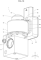
Fig. 16 andFig. 17 illustrate anotherelectric valve 901 according to the related art. Theelectric valve 901 obtains a rotational angle of a magnet rotor in a similar way to the electric valve inPatent Literature 1. Theelectric valve 901 includes avalve body 910, astator 960, ahousing 970, and acase 980. Thehousing 970 includes aperipheral wall portion 971, anupper wall portion 972, adome portion 973, and a connectingportion 975. Theconnecting portion 975 has a quadrangular tubular shape extending in a lateral direction (X direction). The connectingportion 975 includes atip end portion 976 projecting from theperipheral wall portion 971 in the lateral direction. Thecase 980 is bonded to thetip end portion 976. The connectingportion 975 includes atop plate portion 977 in a flat plate-like shape projecting upward from the upper wall portion 972 (Z direction). - The
housing 970 is made of synthetic resin. Thehousing 970 is formed by injection molding. In the formation of thehousing 970 by injection molding, a relatively large weld line may be formed in the central part of thetop plate portion 977 of the connectingportion 975 in a width direction (Y direction). Therefore, there is a possibility that a crack occurs along the weld line. - Accordingly, it is an object of the present invention to provide a stator unit capable of suppressing formation of a weld line, and an electric valve that includes the stator unit.
- To achieve the object described above, a stator unit according to an aspect of the present invention includes a stator, a housing that houses the stator and is made of resin, and a case that is bonded to the housing and is made of resin. The housing integrally includes a peripheral wall portion, an upper wall portion that is connected to the peripheral wall portion, a dome portion that projects upward from the upper wall portion, and a connecting portion in a quadrangular tubular shape that extends in a lateral direction. The connecting portion includes a tip end portion to which the case is bonded, and a top plate portion in a flat plate-like shape that projects upward from the upper wall portion. The tip end portion projects from the peripheral wall portion in the lateral direction. A protrusion is provided in a central part of an upper surface of the top plate portion in a width direction and extends between the dome portion and the tip end portion.
- According to the present invention, the housing includes the connecting portion in the quadrangular tubular shape that extends in the lateral direction. The tip end portion of the connecting portion projects from the peripheral wall portion of the housing in the lateral direction. The top plate portion of the connecting portion has the flat plate-like shape and projects upward from the upper wall portion of the housing. The protrusion is provided on the central part of the upper surface of the top plate portion in the width direction (a direction orthogonal to an extending direction of the connecting portion), and the protrusion extends between the dome portion on the upper wall portion and the tip end portion of the connecting portion. As a result, the central part of the top plate portion in the width direction has a thickness greater than that of the end parts of the top plate portion in the width direction, and a resin is likely to flow into the central part of the top plate portion in the width direction during formation of the housing by injection molding. Therefore, the resin flows into the central part of the top plate portion in the width direction, then the resin spreads to both end parts of the top plate portion in the width direction, and it is possible to suppress formation of a weld line in the central part.
- In the present invention, preferably, a concave surface is provided in a connecting part in which the upper wall portion is connected to the connecting portion and extends in the lateral direction. With this configuration, the connecting part has a small thickness and sink marks of the resin in the connecting part can be suppressed compared with a configuration with a raised connecting part, in which the upper wall portion of the housing is connected to the connecting portion of the housing.
- In the present invention, preferably, the tip end portion of the connecting portion includes a housing bonding surface in a quadrangular frame shape, and a housing reference surface in a quadrangular frame shape that encloses the housing bonding surface. Preferably, the case includes a case bonding surface in a quadrangular frame shape that is bonded to the housing bonding surface, and a case reference surface that encloses the case bonding surface and is in contact with the housing reference surface. Preferably, a first slot is provided in a central part of an upper side of the case reference surface, and a second slot is provided in a central part of a lower side of the case reference surface. The weld line is likely to be formed in the central part of the tip end portion of the connecting portion in the width direction. Even if the central part of the upper side of the housing reference surface and the central part of the lower side of the housing reference surface are raised by weld lines, the first slot in the central part of the upper side of the case reference surface and the second slot in the central part of the lower side of the case reference surface can inhibit portions of the housing reference surface that are raised from coming into contact with the case reference surface. Therefore, the housing reference surface is in proper contact with the case reference surface, and the case can be appropriately bonded to the housing.
- In the present invention, preferably, a lower surface of the top plate portion is located at a position higher than an upper surface of the upper wall portion. With this configuration, the connecting portion is enlarged in an up-down direction, and the tip end portion of the connecting portion can be enlarged. Therefore, the housing bonding surface and the case bonding surface can be enlarged, resulting in firmer bonding of the case to the housing.
- In the present invention, preferably, the case integrally includes a case body in a box shape and a connector in a tubular shape. Preferably, the case body includes a first wall portion that includes the case bonding surface and the case reference surface, and a second wall portion from which the connector extends, and the second wall portion is connected to the first wall portion of the case body. Preferably, a first rib is provided on an outer surface of the first wall portion and extends between the case reference surface and a connecting part in which the first wall portion is connected to the second wall portion. Preferably, a second rib is provided between an outer surface of the second wall portion and an outer circumferential surface of the connector. Preferably, when viewed in a direction of an axis of the connector, the connector is between the first rib and the second rib. With this configuration, it is possible to inhibit the connector from tilting with respect to the case body when the resin cures during formation of the case by injection molding.
- To achieve the object described above, an electric valve according to another aspect of the present invention includes a valve body, a can that is bonded to the valve body, and a stator unit in which the can is housed. The stator unit is the stator unit described above. As a result, it is possible to suppress the formation of the weld line in the housing of the stator unit.
- According to the present invention, it is possible to suppress the formation of the weld line in the housing of the stator unit.
-
- [
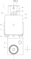
Fig. 1] Fig. 1 is a front view of an electric valve according to an embodiment of the present invention. - [
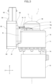
Fig. 2] Fig. 2 is a right-side view of the electric valve inFig. 1 . - [
Fig. 3] Fig. 3 is a back view of the electric valve inFig. 1 . - [
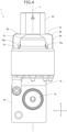
Fig. 4] Fig. 4 is a left-side view of the electric valve inFig. 1 . - [
Fig. 5] Fig. 5 is a plan view of the electric valve inFig. 1 . - [
Fig. 6] Fig. 6 is a bottom view of the electric valve inFig. 1 . - [
Fig. 7] Fig. 7 is a longitudinal sectional view of the electric valve inFig. 1 . - [
Fig. 8] Fig. 8 is a sectional view taken along line VIII-VIII ofFig. 7 . - [
Fig. 9] Fig. 9 is a perspective view of the electric valve inFig. 1 as viewed from an upper right front side. - [
Fig. 10] Fig. 10 is a perspective view of the electric valve inFig. 1 as viewed from a lower left front side. - [
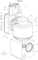
Fig. 11] Fig. 11 is a perspective view of the electric valve inFig. 1 as viewed from an upper left back side. - [
Fig. 12] Fig. 12 is a perspective view of the electric valve inFig. 1 as viewed from a lower left back side. - [
Fig. 13] Fig. 13 is a perspective view of a stator and a housing of a stator unit of the electric valve inFig. 1 . - [
Fig. 14] Fig. 14 is a perspective view of the stator of the stator unit of the electric valve inFig. 1 . - [
Fig. 15] Fig. 15 is a perspective view of a case body and a connector of the stator unit of the electric valve inFig. 1 . - [
Fig. 16] Fig. 16 is a left-side view of an electric valve according to the related art. - [
Fig. 17] Fig. 17 is a perspective view of a stator and a housing of a stator unit of the electric valve inFig. 16 . - An electric valve according to an embodiment of the present invention is described with reference to
Fig. 1 to Fig. 15 . -
Fig. 1 to Fig. 6 are a front view, a right-side view, a back view, a left-side view, a plan view, and a bottom view of the electric valve according to the embodiment of the present invention.Fig. 7 is a sectional view (longitudinal sectional view) taken along an axis L of the electric valve inFig. 1 .Fig. 8 is a sectional view taken along line VIII-VIII ofFig. 7 . InFig. 8 , no members inside a can are illustrated.Fig. 9 is a perspective view of the electric valve inFig. 1 as viewed from an upper right front side.Fig. 10 is a perspective view of the electric valve inFig. 1 as viewed from a lower left front side.Fig. 11 is a perspective view of the electric valve inFig. 1 as viewed from an upper left back side.Fig. 12 is a perspective view of the electric valve inFig. 1 as viewed from a lower left back side.Fig. 13 is a perspective view of a stator and a housing of a stator unit of the electric valve inFig. 1 .Fig. 14 is a perspective view of the stator of the stator unit of the electric valve inFig. 1 .Fig. 15 is a perspective view of a case body and a connector of the stator unit of the electric valve inFig. 1 . In each figure, an X direction is a left-right direction (lateral direction), a Y direction is a front-back direction, and a Z direction is an up-down direction (direction of the axis L). - As illustrated in each figure, an
electric valve 1 includes avalve body 10, acan 20, a drivingsection 30, avalve member 40, and astator unit 50. - The
valve body 10 is made of metal such as an aluminum alloy. Thevalve body 10 includes amain body portion 11, acylindrical portion 12, and aflange portion 13. Themain body portion 11 has a rectangular parallelepiped shape. Thecylindrical portion 12 projects from the upper surface of themain body portion 11. Thecylindrical portion 12 is mounted to themain body portion 11 with a screw structure. Themain body portion 11 includes avalve chamber 14 and flowpassages flow passage 15 is connected to thevalve chamber 14. Theflow passage 16 is connected to thevalve chamber 14 via aport 17. Theflange portion 13 has an annular plate-like shape. The inner peripheral edge of theflange portion 13 is bonded to the upper end of thecylindrical portion 12. - The
can 20 is made of metal such as stainless steel. Thecan 20 has a circular cylindrical shape that is closed at the upper end portion. The lower end portion of thecan 20 is bonded to the outer peripheral edge of theflange portion 13. - The driving
section 30 moves thevalve member 40 in the up-down direction. The drivingsection 30 includes amagnet rotor 31, avalve stem holder 32, aguide bush 33, and avalve stem 34. - The
magnet rotor 31 has a circular cylindrical shape. The outer diameter of themagnet rotor 31 is slightly smaller than the inner diameter of thecan 20. Multiple N poles and multiple S poles are provided on the outer circumferential surface of themagnet rotor 31. The multiple N poles and multiple S poles extend in the up-down direction and are arranged alternately and circumferentially at equal intervals. - The
valve stem holder 32 has a circular cylindrical shape that is closed at the upper end. Thevalve stem holder 32 includes an upper end portion to which a supportingring 35 is fixed. Thevalve stem holder 32 is integrally coupled with themagnet rotor 31 via the supportingring 35. The inner circumferential surface of thevalve stem holder 32 has aninternal thread 32c. - The
guide bush 33 integrally includes a firstcylindrical portion 33a and a secondcylindrical portion 33b. The outer diameter of the secondcylindrical portion 33b is smaller than the outer diameter of the firstcylindrical portion 33a. The secondcylindrical portion 33b is coaxially connected to the upper end portion of the firstcylindrical portion 33a. The outer circumferential surface of the secondcylindrical portion 33b has anexternal thread 33c. Theexternal thread 33c is screwed into theinternal thread 32c of thevalve stem holder 32. The firstcylindrical portion 33a is press-fitted into afitting hole 12a formed in thecylindrical portion 12 of thevalve body 10. Theguide bush 33 is coupled to thevalve body 10. - The valve stem 34 has a circular columnar shape. The valve stem 34 includes an
upper end portion 34a that extends through thevalve stem holder 32. Apush nut 36 as a retainer is attached to theupper end portion 34a of thevalve stem 34. The valve stem 34 extends through theguide bush 33 and thecylindrical portion 12. The lower end portion of thevalve stem 34 is disposed in thevalve chamber 14. Avalve closing spring 37 is disposed between thevalve stem holder 32 and astep portion 34b of thevalve stem 34. Thevalve closing spring 37 is a compression coil spring. Thevalve closing spring 37 pushes thevalve stem 34 downward. - The
valve member 40 is integrally connected to the lower end portion of thevalve stem 34. Thevalve member 40 is disposed in thevalve chamber 14. The drivingsection 30 moves thevalve member 40 in the up-down direction. The movement of thevalve member 40 opens and closes theport 17. - The
stator unit 50 includes astator 60, ahousing 70, and acase 80. - The
stator 60 has a circular cylindrical shape. Thestator 60 and themagnet rotor 31 are members of a stepping motor. Thestator 60 includes anupper stator 61, alower stator 62, and amold 63 made of synthetic resin. - The
upper stator 61 and thelower stator 62 are coaxially disposed. Theupper stator 61 is in contact with thelower stator 62. Theupper stator 61 includes a plurality of claw-pole-type pole teeth 61a. Thepole teeth 61a are arranged circumferentially at equal intervals. Thelower stator 62 includes a plurality of claw-pole-type pole teeth 62a. Thepole teeth 62a are arranged circumferentially at equal intervals. Themold 63 fills theupper stator 61 and thelower stator 62. Themold 63 and thepole teeth circumferential surface 60a of thestator 60. Themold 63 includes aterminal supporting portion 64. - The
terminal supporting portion 64 extends from theupper stator 61 and thelower stator 62 in the lateral direction (X direction). Theterminal supporting portion 64 supports a plurality ofterminals 65. Theterminals 65 extend from the tip end of theterminal supporting portion 64 in the lateral direction. Theterminals 65 are connected to a coil of theupper stator 61 and a coil of thelower stator 62. - The
housing 70 is made of synthetic resin. Thehousing 70 is formed by injection molding. Thehousing 70 has a mirror-symmetric shape with respect to a plane that includes the axis L and is parallel to an XZ plane. Thehousing 70 houses thestator 60. Thehousing 70 integrally includes aperipheral wall portion 71, anupper wall portion 72, adome portion 73, atubular portion 74, and a connectingportion 75. - The
peripheral wall portion 71 has a circular cylindrical shape. Theupper wall portion 72 is connected to the upper end of theperipheral wall portion 71. Thedome portion 73 projects upward from the central part of theupper wall portion 72. Thecan 20 is disposed inside thestator 60 and thedome portion 73. Thetubular portion 74 has a circular cylindrical shape with a smaller diameter than theperipheral wall portion 71. Thetubular portion 74 extends downward from theperipheral wall portion 71. Thetubular portion 74 is disposed around thecylindrical portion 12 of thevalve body 10. Thetubular portion 74 and thecylindrical portion 12 form a gap in which aseal 79 in an annular shape is disposed. Theseal 79 is made of an elastic material such as a rubber material. - The connecting
portion 75 has a quadrangular tubular shape extending in the lateral direction (X direction). The connectingportion 75 includes atip end portion 76 that projects from theperipheral wall portion 71 in the lateral direction. Thetip end portion 76 includes ahousing opening 76a, ahousing bonding surface 76b, and ahousing reference surface 76c. Thehousing opening 76a is an opening in a quadrangular shape. Thehousing opening 76a faces in the lateral direction (X direction, rightward). Thehousing bonding surface 76b is a plane in a quadrangular frame shape. Thehousing bonding surface 76b faces in the same direction as thehousing opening 76a. Thehousing bonding surface 76b is disposed around thehousing opening 76a. Thehousing reference surface 76c is a plane in the quadrangular frame shape. Thehousing reference surface 76c faces in the same direction as thehousing bonding surface 76b. Thehousing reference surface 76c is disposed around thehousing bonding surface 76b. Thehousing reference surface 76c is disposed closer to theperipheral wall portion 71 than thehousing bonding surface 76b is. Theterminal supporting portion 64 of thestator 60 and theterminals 65 of thestator 60 project from thehousing opening 76a. - The connecting
portion 75 has atop plate portion 77 in a flat plate-like shape. Thetop plate portion 77 projects upward from theupper wall portion 72. Thetop plate portion 77 includes anupper surface 77a on which aprotrusion 78 is formed. Theprotrusion 78 extends from thedome portion 73 to thetip end portion 76. Theprotrusion 78 is disposed in the central part of theupper surface 77a in a width direction (Y direction). Thetop plate portion 77 includes alower surface 77b that is entirely flat. Thelower surface 77b is located at a position higher than anupper surface 72a of theupper wall portion 72. A thickness of the central part (where theprotrusion 78 is disposed) of thetop plate portion 77 in the width direction is greater than a thickness of both end parts of thetop plate portion 77 in the width direction. - A
concave surface 75a is formed in a connecting part in which theupper wall portion 72 is connected to the connectingportion 75. Theconcave surface 75a inhibits the connecting part in which theupper wall portion 72 is connected to the connectingportion 75 from being raised. - The
case 80 is made of synthetic resin. Thecase 80 is formed by injection molding. Thecase 80 has a mirror-symmetric shape with respect to the plane that includes the axis L and is parallel to the XZ plane. Thecase 80 includes acase body 81, alid body 82 and aconnector 83. Thecase body 81 has a rectangular parallelepiped box shape with an opening on the side. Thelid body 82 has a flat plate-like shape. Thelid body 82 closes the opening on the side of thecase body 81. Theconnector 83 has a tubular shape with an elliptical transverse section. Theconnector 83 extends upward from thecase body 81. Thecase body 81 and theconnector 83 are integrally formed. - The
case body 81 houses acircuit board 86. Thecircuit board 86 is a printed circuit board on which electronic components are mounted.Magnetic sensors circuit board 86. A microcomputer or the like may be mounted on thecircuit board 86 in addition to themagnetic sensors magnet rotor 31 and a valve opening degree (an opening degree of the port 17) based on output signals from themagnetic sensors terminals 65 of thestator 60 are connected to thecircuit board 86. - The
case body 81 includes a side wall portion 84 (a first wall portion) on a side opposite to thelid body 82. Theside wall portion 84 includes acase opening 84a, acase bonding surface 84b, and acase reference surface 84c. Thecase opening 84a is an opening in the quadrangular shape that faces in the lateral direction (X direction, leftward). Thecase opening 84a is connected to thehousing opening 76a. Thecase bonding surface 84b is a plane in the quadrangular frame shape that faces in the same direction as the case opening 84a. Thecase bonding surface 84b is disposed around the case opening 84a. Thecase bonding surface 84b is bonded to thehousing bonding surface 76b by, for example, infrared welding, ultrasonic welding, or adhesive. Thecase reference surface 84c is a plane in the quadrangular frame shape that faces in the same direction as thecase bonding surface 84b. Thecase reference surface 84c is disposed around thecase bonding surface 84b. Thecase reference surface 84c is disposed closer to theperipheral wall portion 71 than thecase bonding surface 84b is. Afirst slot 84d is formed in the central part of the upper side of thecase reference surface 84c. Asecond slot 84e is formed in the central part of the lower side of thecase reference surface 84c. Thecase reference surface 84c comes into contact with thehousing reference surface 76c. - The
case body 81 includes an upper wall portion 85 (a second wall portion) that is connected to the upper end of theside wall portion 84. Theconnector 83 extends upward from anouter surface 85a of theupper wall portion 85. A direction of an axis of theconnector 83 is parallel to the axis L. Afirst rib 88 is formed on anouter surface 84f of theside wall portion 84. Thefirst rib 88 extends between thefirst slot 84d of the upper side of thecase reference surface 84c and a connecting part in which theside wall portion 84 is connected to theupper wall portion 85. Asecond rib 89 is formed between theouter surface 85a of theupper wall portion 85 and an outercircumferential surface 83a of theconnector 83. Thesecond rib 89 has a plate-like shape that is a right triangle in front view. Thefirst rib 88 and thesecond rib 89 are opposed in the lateral direction when viewed from above, and theconnector 83 is disposed between thefirst rib 88 and thesecond rib 89. - The
stator unit 50 includesmagnetic transmission members 51a, 51b. Themagnetic transmission members 51a, 51b each have a band plate-like shape. Themagnetic transmission members 51a, 51b extend through thehousing opening 76a and the case opening 84a. Themagnetic transmission member 51a includes a first end that faces to the outer circumferential surface of thecan 20. The magnetic transmission member 51b includes a first end that faces to the outer circumferential surface of thecan 20. Themagnetic transmission member 51a includes a second end that faces to a magnetic detection surface of themagnetic sensor 87a. The magnetic transmission member 51b includes a second end that faces to a magnetic detection surface of themagnetic sensor 87b. Themagnetic transmission member 51a transmits the magnetism of the N and S poles of themagnet rotor 31 to themagnetic sensor 87a. The magnetic transmission member 51b transmits the magnetism of the N and S poles of themagnet rotor 31 to themagnetic sensor 87b. - In the
electric valve 1, the respective axes of thecylindrical portion 12 of thevalve body 10, theport 17, thecan 20, themagnet rotor 31, thevalve stem holder 32, theguide bush 33, thevalve stem 34, thevalve member 40, the stator 60 (theupper stator 61 and the lower stator 62), and the housing 70 (thedome portion 73 and the tubular portion 74) are aligned with the axis L. - The operation of the
electric valve 1 is described below. - In the
electric valve 1, a current is applied to theupper stator 61 and thelower stator 62 to rotate themagnet rotor 31 in one direction. Thevalve stem holder 32 rotates together with themagnet rotor 31. A screw-feed action between theinternal thread 32c of thevalve stem holder 32 and theexternal thread 33c of theguide bush 33 moves thevalve stem holder 32 downward. The valve stem 34 moves downward together with thevalve stem holder 32, and thevalve member 40 closes the port 17 (valve-closing state). - In the
electric valve 1, a current is applied to theupper stator 61 and thelower stator 62 to rotate themagnet rotor 31 in the other direction. Thevalve stem holder 32 rotates together with themagnet rotor 31. The screw-feed action between theinternal thread 32c of thevalve stem holder 32 and theexternal thread 33c of theguide bush 33 moves thevalve stem holder 32 upward. The valve stem 34 moves upward together with thevalve stem holder 32, and thevalve member 40 opens the port 17 (valve-opening state). - As described above, the
electric valve 1 of the present embodiment includes thestator unit 50. Thestator unit 50 includes thestator 60, thehousing 70 that houses thestator 60, and thecase 80 that is bonded to thehousing 70. Thehousing 70 integrally includes theperipheral wall portion 71, theupper wall portion 72 that is connected to theperipheral wall portion 71, thedome portion 73 that projects upward from theupper wall portion 72, and the connectingportion 75 in the quadrangular tubular shape that extends in the lateral direction. The connectingportion 75 includes thetip end portion 76 and thetop plate portion 77. Thetip end portion 76 projects from theperipheral wall portion 71 in the lateral direction. Thecase 80 is bonded to thetip end portion 76. Thetop plate portion 77 has a flat plate-like shape. Thetop plate portion 77 projects upward from theupper wall portion 72. Theprotrusion 78 is provided in the central part of theupper surface 77a of thetop plate portion 77 in the width direction and extends between thedome portion 73 and thetip end portion 76. - According to the
electric valve 1, the central part of thetop plate portion 77 in the width direction has the thickness greater than that of the end parts of thetop plate portion 77 in the width direction. As a result, a resin is likely to flow into the central part of thetop plate portion 77 in the width direction during formation of thehousing 70 by injection molding. Therefore, the resin flows into the central part of thetop plate portion 77 in the width direction, then the resin spreads to the both end parts of thetop plate portion 77 in the width direction, and it is possible to suppress formation of a weld line in the central part. - The
concave surface 75a is provided in the connecting part in which theupper wall portion 72 of thehousing 70 is connected to the connectingportion 75 of thehousing 70 and extends in the lateral direction. With this configuration, the connecting part has a small thickness and sink marks of the resin in the connecting part can be suppressed compared with a configuration with a raised connecting part, in which theupper wall portion 72 is connected to the connectingportion 75. - The
tip end portion 76 of the connectingportion 75 includes thehousing bonding surface 76b in the quadrangular frame shape, and thehousing reference surface 76c in the quadrangular frame shape that encloses thehousing bonding surface 76b. Thecase 80 includes thecase bonding surface 84b in the quadrangular frame shape, and thecase reference surface 84c that encloses thecase bonding surface 84b. Thecase bonding surface 84b is bonded to thehousing bonding surface 76b. Thecase reference surface 84c is in contact with thehousing reference surface 76c. Thefirst slot 84d is provided in the central part of the upper side of thecase reference surface 84c. Thesecond slot 84e is provided in the central part of the lower side of thecase reference surface 84c. The weld line is likely to be formed in the central part of thetip end portion 76 of the connectingportion 75 in the width direction (Y direction). Even if the central part of the upper side of thehousing reference surface 76c and the central part of the lower side of thehousing reference surface 76c are raised by weld lines, thefirst slot 84d in the central part of the upper side of thecase reference surface 84c and thesecond slot 84e in the central part of the lower side of thecase reference surface 84c can inhibit portions of thehousing reference surface 76c that are raised from coming into contact with thecase reference surface 84c. Therefore, thehousing reference surface 76c is in proper contact with thecase reference surface 84c, and thecase 80 can be appropriately bonded to thehousing 70. - The
lower surface 77b of thetop plate portion 77 is located at the position higher than theupper surface 72a of theupper wall portion 72. With this configuration, the connectingportion 75 is enlarged in an up-down direction, and thetip end portion 76 of the connectingportion 75 can be enlarged. Therefore, thehousing bonding surface 76b and thecase bonding surface 84b are enlarged, resulting in firmer bonding of thecase 80 to thehousing 70. - The
case 80 integrally includes thecase body 81 in the rectangular box shape and theconnector 83 in the elliptical tubular shape. Thecase body 81 includes theside wall portion 84 and theupper wall portion 85. Theside wall portion 84 includes thecase bonding surface 84b and thecase reference surface 84c. Theupper wall portion 85 includes theouter surface 85a from which theconnector 83 extends. Theupper wall portion 85 is connected to theside wall portion 84. Thefirst rib 88 is provided on theouter surface 84f of theside wall portion 84 and extends between thecase reference surface 84c and the connection part in which theside wall portion 84 is connected to theupper wall portion 85. Thesecond rib 89 is provided between theouter surface 85a of theupper wall portion 85 and the outercircumferential surface 83a of theconnector 83. Theconnector 83 is disposed between thefirst rib 88 and thesecond rib 89 when viewed from above (the direction of the axis of the connector 83). With this configuration, it is possible to inhibit theconnector 83 from tilting with respect to thecase body 81 when the resin cures during formation of thecase 80 by injection molding. - The embodiment of the present invention is described above. The present invention, however, is not limited to the embodiment. Embodiments obtained by appropriately adding, removing, or modifying components according to the embodiment described above by a person skilled in the art, and an embodiment obtained by appropriately combining features of the embodiment are included in the scope of the present invention as long as they have the gist of the present invention.
- 1 ... electric valve, 10 ... valve body, 11 ... main body portion, 12 ... cylindrical portion, 12a ... fitting hole, 13 ... flange portion, 14 ... valve chamber, 15, 16 ... flow passage, 17 ... port, 20 ... can, 30 ... driving section, 31 ... magnet rotor, 32 ... valve stem holder, 32c ... internal thread, 33 ... guide bush, 33a ... first cylindrical portion, 33b ... second cylindrical portion, 33c ... external thread, 34 ... valve stem, 34a ... upper end portion, 34b ... step portion, 35 ... supporting ring, 36 ... push nut, 37 ... valve closing spring, 40 ... valve member, 50 ... stator unit, 51a, 51b ... magnetic transmission member, 60 ... stator, 60a ... inner circumferential surface, 61 ... upper stator, 61a ... pole teeth, 62 ... lower stator, 62a... pole teeth, 63 ... mold, 64 ... terminal supporting portion, 65 ... terminal, 70 ... housing, 71 ... peripheral wall portion, 72 ... upper wall portion, 72a ... upper surface, 73 ... dome portion, 74 ... tubular portion, 75 ... connecting portion, 75a ... concave surface, 76 ... tip end portion, 76a ... housing opening, 76b ... housing bonding surface, 76c ... housing reference surface, 77 ... top plate portion, 77a ... upper surface, 77b ... lower surface, 78 ... protrusion, 79 ... seal, 80 ... case, 81 ... case body, 82 ... lid body, 83 ... connector, 83a ... outer circumferential surface, 84 ... side wall portion, 84a ... case opening, 84b ... case bonding surface, 84c ... case reference surface, 84d ...first slot, 84e ... second slot, 84f ... outer surface, 85 ... upper wall portion, 85a ... outer surface, 86 ... circuit board, 87a, 87b ... magnetic sensor, 88 ... first rib, 89 ... second rib
Claims (6)
- A stator unit comprising:a stator;a housing that houses the stator and is made of resin; anda case that is bonded to the housing and is made of resin,wherein the housing integrally includes a peripheral wall portion, an upper wall portion that is connected to the peripheral wall portion, a dome portion that projects upward from the upper wall portion, and a connecting portion in a quadrangular tubular shape that extends in a lateral direction,wherein the connecting portion includes a tip end portion to which the case is bonded, and a top plate portion in a flat plate-like shape that projects upward from the upper wall portion, the tip end portion projecting from the peripheral wall portion in the lateral direction, andwherein a protrusion is provided in a central part of an upper surface of the top plate portion in a width direction and extends between the dome portion and the tip end portion.
- The stator unit according to Claim 1, wherein a concave surface is provided in a connecting part in which the upper wall portion is connected to the connecting portion and extends in the lateral direction.
- The stator unit according to Claim 1 or Claim 2,wherein the tip end portion of the connecting portion includes a housing bonding surface in a quadrangular frame shape and a housing reference surface in a quadrangular frame shape that encloses the housing bonding surface,wherein the case includes a case bonding surface in a quadrangular frame shape that is bonded to the housing bonding surface, and a case reference surface that encloses the case bonding surface and is in contact with the housing reference surface, andwherein a first slot is provided in a central part of an upper side of the case reference surface, and a second slot is provided in a central part of a lower side of the case reference surface.
- The stator unit according to Claim 3, wherein a lower surface of the top plate portion is located at a position higher than an upper surface of the upper wall portion.
- The stator unit according to Claim 3 or Claim 4,wherein the case integrally includes a case body in a box shape and a connector in a tubular shape,wherein the case body includes a first wall portion that includes the case bonding surface and the case reference surface, and a second wall portion from which the connector extends, the second wall portion being connected to the first wall portion of the case body,wherein a first rib is provided on an outer surface of the first wall portion and extends between the case reference surface and a connecting part in which the first wall portion is connected to the second wall portion,wherein a second rib is provided between an outer surface of the second wall portion and an outer circumferential surface of the connector, andwherein when viewed in a direction of an axis of the connector, the connector is between the first rib and the second rib.
- An electric valve comprising:a valve body;a can that is bonded to the valve body; anda stator unit in which the can is housed,wherein the stator unit is the stator unit according to any one of Claim 1 to Claim 5.
Applications Claiming Priority (2)
| Application Number | Priority Date | Filing Date | Title |
|---|---|---|---|
| JP2020164879A JP7384412B2 (en) | 2020-09-30 | 2020-09-30 | Manufacturing method of stator unit |
| PCT/JP2021/030756 WO2022070668A1 (en) | 2020-09-30 | 2021-08-23 | Stator unit and electric valve |
Publications (2)
| Publication Number | Publication Date |
|---|---|
| EP4224681A1 true EP4224681A1 (en) | 2023-08-09 |
| EP4224681A4 EP4224681A4 (en) | 2024-11-13 |
Family
ID=80949958
Family Applications (1)
| Application Number | Title | Priority Date | Filing Date |
|---|---|---|---|
| EP21874971.1A Pending EP4224681A4 (en) | 2020-09-30 | 2021-08-23 | Stator unit and electric valve |
Country Status (5)
| Country | Link |
|---|---|
| EP (1) | EP4224681A4 (en) |
| JP (3) | JP7384412B2 (en) |
| KR (1) | KR20230074715A (en) |
| CN (1) | CN116018474A (en) |
| WO (1) | WO2022070668A1 (en) |
Families Citing this family (2)
| Publication number | Priority date | Publication date | Assignee | Title |
|---|---|---|---|---|
| JP7669043B2 (en) * | 2022-07-26 | 2025-04-28 | 株式会社不二工機 | Motor-operated valve, motor-operated valve device, and method for assembling the motor-operated valve device |
| CN119341259B (en) * | 2024-12-23 | 2025-02-28 | 厦门欣众达科技有限公司 | A motor sealing and waterproof device for underwater robot |
Family Cites Families (23)
| Publication number | Priority date | Publication date | Assignee | Title |
|---|---|---|---|---|
| JP2000297873A (en) | 1999-04-15 | 2000-10-24 | Fuji Koki Corp | Motor-operated valve |
| JP2002112578A (en) * | 2000-09-29 | 2002-04-12 | Toyoda Mach Works Ltd | Position-measuring device and motor controller |
| JP4220178B2 (en) * | 2001-09-03 | 2009-02-04 | 株式会社鷺宮製作所 | Motorized valve |
| JP4739857B2 (en) | 2005-08-12 | 2011-08-03 | 東芝産業機器製造株式会社 | Resin can for canned motor and manufacturing method thereof, injection mold, canned motor, canned motor pump |
| JP2008289260A (en) | 2007-05-16 | 2008-11-27 | Nsk Ltd | Rotating electric machine and electric power steering device |
| WO2008140102A1 (en) * | 2007-05-16 | 2008-11-20 | Nsk Ltd. | Rotating electric machine and electric power steering device |
| CN101498378B (en) * | 2008-01-31 | 2012-01-11 | 浙江三花股份有限公司 | Electric valve |
| JP4787896B2 (en) * | 2009-08-28 | 2011-10-05 | 株式会社不二工機 | Motorized valve |
| JP5590936B2 (en) * | 2010-03-30 | 2014-09-17 | 株式会社不二工機 | Motorized valve |
| JP5965712B2 (en) | 2012-04-25 | 2016-08-10 | 株式会社不二工機 | Stator of drive motor for electric valve |
| WO2015004873A1 (en) * | 2013-07-10 | 2015-01-15 | パナソニックIpマネジメント株式会社 | Rotation angle detection device |
| JP6127920B2 (en) * | 2013-11-06 | 2017-05-17 | 住友電装株式会社 | Wire harness and binding tool |
| JP6434236B2 (en) * | 2014-07-03 | 2018-12-05 | 株式会社不二工機 | Motorized valve |
| JP6352741B2 (en) * | 2014-09-11 | 2018-07-04 | 株式会社ケーヒン | Power converter |
| JP2016123218A (en) | 2014-12-25 | 2016-07-07 | 株式会社不二工機 | Coil device and electric driving valve using the same |
| CN106953496B (en) * | 2016-01-06 | 2020-08-14 | 浙江三花汽车零部件有限公司 | Stepping motor coil device and electronic valve |
| JP6894250B2 (en) | 2017-02-14 | 2021-06-30 | 日本電産サンキョー株式会社 | Motor and pump equipment |
| JP2018143048A (en) * | 2017-02-28 | 2018-09-13 | 日本電産テクノモータ株式会社 | Method for molding resin casing and motor |
| JP6518713B2 (en) | 2017-04-12 | 2019-05-22 | 株式会社不二工機 | Motorized valve |
| JP6621789B2 (en) | 2017-10-30 | 2019-12-18 | 株式会社不二工機 | Motorized valve |
| CN107830223B (en) * | 2017-12-05 | 2023-05-16 | 浙江中宝自控元件有限公司 | Valve body and coil positioning structure of electronic expansion valve |
| CN112555487A (en) | 2018-06-15 | 2021-03-26 | 杭州三花研究院有限公司 | Electric valve |
| CN211344067U (en) * | 2019-11-11 | 2020-08-25 | 中山市港利制冷配件有限公司 | Electric valve |
-
2020
- 2020-09-30 JP JP2020164879A patent/JP7384412B2/en active Active
-
2021
- 2021-08-23 WO PCT/JP2021/030756 patent/WO2022070668A1/en not_active Ceased
- 2021-08-23 CN CN202180054172.5A patent/CN116018474A/en active Pending
- 2021-08-23 EP EP21874971.1A patent/EP4224681A4/en active Pending
- 2021-08-23 KR KR1020237007353A patent/KR20230074715A/en active Pending
-
2023
- 2023-10-18 JP JP2023179240A patent/JP7618289B2/en active Active
-
2024
- 2024-12-17 JP JP2024220512A patent/JP7772420B2/en active Active
Also Published As
| Publication number | Publication date |
|---|---|
| JP7772420B2 (en) | 2025-11-18 |
| JP2025032355A (en) | 2025-03-11 |
| WO2022070668A1 (en) | 2022-04-07 |
| JP7618289B2 (en) | 2025-01-21 |
| JP2024001227A (en) | 2024-01-09 |
| JP2022056892A (en) | 2022-04-11 |
| JP7384412B2 (en) | 2023-11-21 |
| CN116018474A (en) | 2023-04-25 |
| KR20230074715A (en) | 2023-05-31 |
| EP4224681A4 (en) | 2024-11-13 |
Similar Documents
| Publication | Publication Date | Title |
|---|---|---|
| JP7588882B2 (en) | Motor-operated valve | |
| US11585458B2 (en) | Electronic expansion valve | |
| US9077231B2 (en) | Motor | |
| JP2025032355A (en) | Stator unit and motor-operated valve | |
| JP7368023B2 (en) | electric valve | |
| US20110260719A1 (en) | Rotational angle sensors and manufacture methods thereof | |
| WO2022168652A1 (en) | Electric valve | |
| US20220263395A1 (en) | Electric Actuating Unit | |
| CN218782884U (en) | Coil structure for electronic expansion valve, electronic expansion valve and motor vehicle | |
| US20190359193A1 (en) | Electric component assembly, and brake fluid pressure control device for vehicle | |
| JP2014149188A (en) | Stroke sensor | |
| CN115596871A (en) | Electric valve | |
| JP2025003651A (en) | Stator unit, motorized valve and motorized valve device | |
| USRE47564E1 (en) | Motor | |
| JP2023165815A (en) | electric valve | |
| US10605378B2 (en) | Sensor unit | |
| JP2001004057A (en) | Motor operated valve | |
| JP2005291266A (en) | Electric valve | |
| JP2020128968A (en) | Moving body detection device, and manufacturing method of moving body detection device | |
| JP5123982B2 (en) | Brake hydraulic pressure control device for vehicles | |
| CN111853318A (en) | Valve element driving device | |
| JP2017150912A (en) | Liquid level detector | |
| JP2011230657A (en) | Brake hydraulic pressure control apparatus for vehicle |
Legal Events
| Date | Code | Title | Description |
|---|---|---|---|
| STAA | Information on the status of an ep patent application or granted ep patent |
Free format text: STATUS: THE INTERNATIONAL PUBLICATION HAS BEEN MADE |
|
| PUAI | Public reference made under article 153(3) epc to a published international application that has entered the european phase |
Free format text: ORIGINAL CODE: 0009012 |
|
| STAA | Information on the status of an ep patent application or granted ep patent |
Free format text: STATUS: REQUEST FOR EXAMINATION WAS MADE |
|
| 17P | Request for examination filed |
Effective date: 20230308 |
|
| AK | Designated contracting states |
Kind code of ref document: A1 Designated state(s): AL AT BE BG CH CY CZ DE DK EE ES FI FR GB GR HR HU IE IS IT LI LT LU LV MC MK MT NL NO PL PT RO RS SE SI SK SM TR |
|
| DAV | Request for validation of the european patent (deleted) | ||
| DAX | Request for extension of the european patent (deleted) | ||
| A4 | Supplementary search report drawn up and despatched |
Effective date: 20241016 |
|
| RIC1 | Information provided on ipc code assigned before grant |
Ipc: B29C 45/14 20060101ALI20241010BHEP Ipc: B29C 45/00 20060101ALI20241010BHEP Ipc: B29L 31/34 20060101ALI20241010BHEP Ipc: F16K 31/50 20060101ALI20241010BHEP Ipc: F16K 27/02 20060101ALI20241010BHEP Ipc: F16K 37/00 20060101ALI20241010BHEP Ipc: H02K 5/22 20060101ALI20241010BHEP Ipc: H02K 5/128 20060101ALI20241010BHEP Ipc: H02K 11/215 20160101ALI20241010BHEP Ipc: H02K 11/33 20160101ALI20241010BHEP Ipc: H02K 5/12 20060101ALI20241010BHEP Ipc: F16K 31/04 20060101ALI20241010BHEP Ipc: H02K 5/08 20060101AFI20241010BHEP |
|
| STAA | Information on the status of an ep patent application or granted ep patent |
Free format text: STATUS: EXAMINATION IS IN PROGRESS |
|
| 17Q | First examination report despatched |
Effective date: 20260306 |
|
| STAA | Information on the status of an ep patent application or granted ep patent |
Free format text: STATUS: THE APPLICATION HAS BEEN WITHDRAWN |