EP4224650A1 - Adaptation module for a gas-insulated switchgear - Google Patents
Adaptation module for a gas-insulated switchgear Download PDFInfo
- Publication number
- EP4224650A1 EP4224650A1 EP22154809.2A EP22154809A EP4224650A1 EP 4224650 A1 EP4224650 A1 EP 4224650A1 EP 22154809 A EP22154809 A EP 22154809A EP 4224650 A1 EP4224650 A1 EP 4224650A1
- Authority
- EP
- European Patent Office
- Prior art keywords
- conductors
- adaptation module
- previous
- module according
- piece
- Prior art date
- Legal status (The legal status is an assumption and is not a legal conclusion. Google has not performed a legal analysis and makes no representation as to the accuracy of the status listed.)
- Granted
Links
Images


Classifications
-
- H—ELECTRICITY
- H02—GENERATION; CONVERSION OR DISTRIBUTION OF ELECTRIC POWER
- H02B—BOARDS, SUBSTATIONS OR SWITCHING ARRANGEMENTS FOR THE SUPPLY OR DISTRIBUTION OF ELECTRIC POWER
- H02B13/00—Arrangement of switchgear in which switches are enclosed in, or structurally associated with, a casing, e.g. cubicle
- H02B13/02—Arrangement of switchgear in which switches are enclosed in, or structurally associated with, a casing, e.g. cubicle with metal casing
- H02B13/035—Gas-insulated switchgear
-
- H—ELECTRICITY
- H02—GENERATION; CONVERSION OR DISTRIBUTION OF ELECTRIC POWER
- H02B—BOARDS, SUBSTATIONS OR SWITCHING ARRANGEMENTS FOR THE SUPPLY OR DISTRIBUTION OF ELECTRIC POWER
- H02B13/00—Arrangement of switchgear in which switches are enclosed in, or structurally associated with, a casing, e.g. cubicle
- H02B13/02—Arrangement of switchgear in which switches are enclosed in, or structurally associated with, a casing, e.g. cubicle with metal casing
- H02B13/035—Gas-insulated switchgear
- H02B13/0358—Connections to in or out conductors
-
- H—ELECTRICITY
- H02—GENERATION; CONVERSION OR DISTRIBUTION OF ELECTRIC POWER
- H02B—BOARDS, SUBSTATIONS OR SWITCHING ARRANGEMENTS FOR THE SUPPLY OR DISTRIBUTION OF ELECTRIC POWER
- H02B13/00—Arrangement of switchgear in which switches are enclosed in, or structurally associated with, a casing, e.g. cubicle
- H02B13/005—Electrical connection between switchgear cells
-
- H—ELECTRICITY
- H02—GENERATION; CONVERSION OR DISTRIBUTION OF ELECTRIC POWER
- H02B—BOARDS, SUBSTATIONS OR SWITCHING ARRANGEMENTS FOR THE SUPPLY OR DISTRIBUTION OF ELECTRIC POWER
- H02B13/00—Arrangement of switchgear in which switches are enclosed in, or structurally associated with, a casing, e.g. cubicle
- H02B13/02—Arrangement of switchgear in which switches are enclosed in, or structurally associated with, a casing, e.g. cubicle with metal casing
- H02B13/035—Gas-insulated switchgear
- H02B13/0352—Gas-insulated switchgear for three phase switchgear
-
- H—ELECTRICITY
- H02—GENERATION; CONVERSION OR DISTRIBUTION OF ELECTRIC POWER
- H02B—BOARDS, SUBSTATIONS OR SWITCHING ARRANGEMENTS FOR THE SUPPLY OR DISTRIBUTION OF ELECTRIC POWER
- H02B13/00—Arrangement of switchgear in which switches are enclosed in, or structurally associated with, a casing, e.g. cubicle
- H02B13/02—Arrangement of switchgear in which switches are enclosed in, or structurally associated with, a casing, e.g. cubicle with metal casing
- H02B13/035—Gas-insulated switchgear
- H02B13/045—Details of casing, e.g. gas tightness
Definitions
- the invention relates to an adaptation module configured for connecting three conductors of two modules and/or bays of a three-phase encapsulated gas-insulated switchgear.
- switchgear In an electric power system, switchgear is composed of electrical disconnect switches, fuses or circuit breakers used to control, protect and isolate electrical equipment. Switchgear is used both to de-energize equipment to allow work to be done and to clear faults downstream.
- Gas-insulated switchgear, GIS is a form of switchgear where conductors and contacts are insulated by pressurized gas, mainly sulfur hexafluoride gas, SF6. For environmental reason alternative insulation gases are under development to replace SF6.
- Switchgear in substations is typically located on both the high- and low-voltage sides of large power transformers.
- Such switchgear usually comprises different modules and/or bays, for example circuit breakers, disconnector and earthing switches, gas-insulated voltage transformers, cast-resin current transformers, air- or gas-insulated surge arresters or the like.
- incoming and outgoing lines or cables may have different phase orientations, which makes it necessary to adapt a conductor connection in a three-phase encapsulated GIS between the modules or bays by angle rotation or complete phase cross-over change by means of turning modules or cross-over conductors.
- As different layouts require different variants of this rotation angle several modules with different phase shift and cross-over conductors are required to achieve the correct phase orientation through the whole GIS.
- a high number of variants exist, which different busduct and angle piece configurations, such as T- or X-modules with a different number of conductor sets.
- Today, for an angle piece a number of 36 variants exists.
- there are further variants in the circuit breaker, and busducts Such high number of variants lead to higher engineering efforts, storage and production costs. Further, if during engineering a wrong rotation was planned, new material is necessary to correct the failure.
- an adaptation module configured for connecting three conductors of two modules and/or bays of a three-phase encapsulated gas-insulated switchgear, comprising
- the proposed solution takes advantage from concentric conductors preferably in the middle of the module preferably with a set of three different connection pieces to the insulators. Such solution makes it possible to provide all possible phase angle shifts or phase cross-over or a combination of both withing one module.
- the conductor connection inlets at the insulators can be shifted and placed in any angle.
- the layout can be adjusted during assembly. In case of wrong planning the same parts can be used to achieve the correct layout.
- the proposed solution leads to lower engineering efforts, storage and production costs.
- the adaptation module can be configured for firmly fixing between two modules and/or bays for example by means of screws, whereby said screws can be arranged in a ring-like manner around the conductor connection inlets on the insulators.
- the modules and/or bays can be provided as, for example, circuit breakers, disconnector and earthing switches, gas-insulated voltage transformers, cast-resin current transformers, air- or gas-insulated surge arresters or the like of the gas-insulated switchgear.
- the insulators preferably comprise a disc-like and/or round flat form to which the conductor connection inlets are attached.
- the conductor connection inlets are preferably provided as electrodes for electrically contacting respective electrodes of the modules and/or bays.
- the conductor connection inlets are preferably radially spaced in respect to the axis in regular distances. Spaced from each other in respect to the conductors means that the conductors are arranged distant from each other without electrically contacting an adjacent conductor. Rotatable in respect to the axis means that the conductors can be rotated in respect to their axis such that, by rotating, the respective opposite arranged conductor connection inlets can be rotated into different angular positions in respect to each other.
- At least one of the conductors comprises two opposite arranged radially extending connection pieces connecting the respective conductor to both respective conductor connection inlets.
- Preferably all conductors comprise respective connection pieces.
- the connection pieces preferably provide a radial and/or axial offset between the connectors and the insulators.
- the connection pieces can be understood as a radial and/or axial extension of the connectors for providing an electrical connection to arts the conductor connection inlets.
- the connection pieces can be provided as busbars or metal rods.
- connection pieces connected to a respective conductor can be differently orientated, for example one connection piece can be radially orientated upwards in respect to the axis while the other connection piece is radially orientated downwards in respect to the axis.
- Opposite arranged means that in axial extension the respective conductor is arranged in-between the two respective connection pieces.
- connection pieces are attached rotatable to the respective conductor.
- the connection pieces are preferably undetachable but rotatable attached to the conductor, for example by clipping.
- An axial end of the conductor and/or an axial end of the connection piece may be provided with an in particular circumferential groove extending in radial direction, to which the connection piece and/or the conductor is connected, for example by means of a sliding contact.
- the respective connection piece is provided one-piece with the respective conductor or at least a part thereof.
- the connection piece can for example be manufactured as one-piece together with the respective conductor or at least a part thereof.
- the one-piece is provided as a casted element.
- the respective conductor and the connection piece can be manufactured by pouring a liquid material into a respective mold, which contains a hollow cavity of the desired shape of the respective conductor and the connection piece.
- At least two of the conductors surround radially at least one other of the conductors.
- the outmost conductor radially surrounds both the middle and innermost conductor, while the middle conductor also radially surrounds the innermost conductor.
- At least two preferably all conductors are provided as tubes.
- the conductors are provided as elongated metal and thus electrically conducting tubes.
- the conductors may comprise an identical axial extension, preferably the innermost conductor is larger in its axial extension than the middle conductor, while the middle conductor is also larger in its axial extension then the outermost conductor.
- the conductors may comprise at their axial ends a lateral radially extending edge or rim, to which the connection piece is attached.
- the conductors are provided two-piece and one piece is rotatable in respect the other piece.
- the conductors are undetachable attached to each other, for example clipped together, while being rotatable in respect to each other.
- the two pieces are attached in a ring-like manner together.
- the two pieces preferably each exhibit a radially extending surface, for example in form of a round, disc-shaped or square surface with a hole, that are attached together.
- At least one piece comprises a sliding contact configured for electrically contacting the other piece.
- the other piece comprises an annular contact element and/or an annular groove configured for receiving the sliding contact.
- Witch such sliding contact and groove a reliable electrical connection between the two pieces can be achieved, while allowing the conductors to rotate across the axis.
- the sliding contact and/or the groove extend in radial direction and/or across the complete annular extension and/or circumferential around the axis.
- the three conductors are rotatable by a rotation angle ⁇ ⁇ 0° and ⁇ 360° in respect to the axis.
- the conductors are rotatable by a rotation angle ⁇ ⁇ 0° and ⁇ 180°, ⁇ ⁇ 0° and ⁇ 90° or ⁇ ⁇ 0° and ⁇ 45° in respect to the axis.
- the conductors axially extend over at least over 0.1, 0.2, 0.5, 1, 2 or 5 meters. Such way a tube connection can be realized. Due to a mainly concentric arrangement of the conductors forces during an eventually short circuit will compensate each other.
- the conductors are bent along their axis with a bending angle ⁇ ⁇ 0° and ⁇ 180°.
- the conductors may comprise an angle of for example 45° or 90°, while still concentric.
- the three conductor connection inlets are radially spaced as equilateral triangle.
- the conductor connection inlets are arrange in regular distances around the axis, thereby providing a kind of interface with locally defined electrodes for electrically connecting the adaptation module to a module and/or bay.
- a gas-insulated switchgear comprising at least two modules and/or bays and an adaption module according to any of the previous claims, whereby the adaptation module connects the three conductors of two modules and/or bays.
- the gas-insulated switchgear is preferably configured for high voltages.
- the term high voltage relates to voltages that exceeds 1 kV.
- a high voltage preferably concerns nominal voltages in the range from above 72 kV to 800 kV, like 145 kV, 245 kV or 420 kV.
- the gas insulated switchgear may be provided as a circuit breaker and/or may include one or more components such as, a puffer-type cylinder, a self-blast chamber, a pressure collecting space, a compression space, or puffer volume, and an expansion space.
- the gas insulated switchgear may effectuate interruption of contact elements by means of one or more of such components, thereby discontinuing flow of electrical current in the contact elements, and/or extinction of the arc produced when the contact elements is interrupted.
- the gas-insulated switchgear preferably comprises an insulating gas which can be any suitable gas that enables to adequately extinguish an electric arc formed between the contact elements during a current interruption operation, such as, but not limited, to an inert gas as, for example, sulphur hexafluoride SF6.
- the insulating gas used can be SF6 gas or any other dielectric insulation medium, may it be gaseous and/or liquid, and in particular can be a dielectric insulation gas or arc quenching gas.
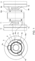
- Fig. 1 shows an adaptation module configured for connecting three conductors 5, 6, 7 of two modules and/or bays 12 of a three-phase encapsulated gas-insulated switchgear, left in a front view and right in a side view, according to a preferred implementation.
- Figs. 2 to 4 show the adaptation module of Fig. 1 left in the front view and right in a back view according to three different configurations.
- the adaptation module comprises two opposite arranged insulators 1a, 1b, which are each provided as disc-like rounded slices or flat rings.
- the adaptation module can be connected on each side to a module and/or bay 12, only schematically shown with dotted lines, of a three-phase encapsulated gas-insulated switchgear, GIS.
- module and/or bay 12 may comprise, for example, a circuit breaker, a disconnector and earthing switch, a gas-insulated voltage transformer, a cast-resin current transformer, an air- or gas-insulated surge arrester or the like.
- the insulators 1a, 1b are firmly fixed to the respect module and/or bay 12 by means of 12 or 24 screws, not shown, which can be arranged in regular intervals.
- the three conductors 5, 6, 7 are provided as axially extending tubes having different radial diameters and are arranged in regular distances around a concentric manner around axis 11 of the adaptation module thereby radially surround each other.
- outmost conductor 5 comprises the largest diameter and the smallest axial extension
- innermost conductor 7 comprises the smallest diameter and the biggest axial extension.
- Inner conductor 6 comprises a smaller diameter than the outmost conductor 5 and a larger diameter than the innermost conductor 7, and comprises a larger axial extension than the outmost conductor 5 and a smaller axial extension than the innermost conductor 7.
- inner conductor 6 is radially arranged between outmost conductor 5 and innermost conductor 7 such that all conductors 5, 6, 7 are arranged spaced from each.
- Each insulator 1a, 1b comprises three conductor connection inlets 2, 3, 4, which are radially spaced in forming an equilateral triangle, as can be in Fig. 1 left.
- the connection inlets 2, 3, 4 are provided as flat electrodes and are integrated in the insulators 1a, 1b.
- Each one of the conductors 5, 6, 7 is connected to a respective connection inlet 2, 3, 4 of both insulators 1a, 1b by means of a radially extending connection piece 8a, 8b, 9a, 9b, 10a, 10b.
- Said extending connection pieces 8a, 8b, 9a, 9b, 10a, 10b form a radial offset between the respective conductor 5, 6, 7 and the respective connection inlet 2, 3, 4.
- innermost conductor 7 is on the left side connected by an upward oriented connection piece 8a to the respective connection inlet 2 on the left insulator 1a and is on the right side connected by a downward oriented connection piece 8b to the respective connection inlet 2 of the right insulator 1b.
- the conductors 5, 6, 7 are provided rotatable in respect to the axis 11. This means that the conductors 5, 6, 7 can be rotated such that the angular orientation of the two opposite arranged oriented connection pieces 8a, 8b, 9a, 9b, 10a, 10b can be changed.
- the adaptation module allows different angular orientations of the respective opposite connection inlets 2, 3, 4 in respect to each other, of which some exemplary orientations are described in the following.
- Fig. 2 shows the adaptation module of Fig. 1 , left in the front view and right in a back view, according to the preferred implementation in a first configuration providing a phase shift of 30° between the insulators 1a, 1b.
- right insulator 1b comprising right conductor connection inlets 2b, 3b, 4b is rotated by 30° clockwise against left insulator 1a comprising left conductor connection inlets 2a, 3a, 4a.
- Such wise right connection pieces 8b, 9b, 10b b follow the rotation resulting in a 30° phase shift without cross-over between the opposite connection inlets 2, 3, 4 respectively the opposite modules and/or bays 12.
- Fig. 3 shows the adaptation module of Fig. 1 , left in the front view and right in a back view, according to the preferred implementation in a second configuration providing a cross-over for connection inlets 2 and 3 i.e. for the first and second connection inlet 2, 3 but not for the third connection inlet 4, and with no phase shift.
- left connection inlet 2a of left insulator 1a is connected over first left and right connection pieces 8a and 8b with second, right connection inlet 3b of right insulator 1b.
- left connection inlet 3a of left insulator 1a is connected over second left and right connection pieces 9a and 9b with second right connection inlet 2b of right insulator 1b.
- Third connection inlet 4 is connected straight from left insulator 1a to right insulator 1b without any cross-over.
- Fig. 4 shows the adaptation module of Fig. 1 , left in the front view and right in a back view, according to the preferred implementation in a third configuration providing a phase shift of 60° with a cross-over second and third connection inlets 3 and 4. Specifically, all right connection inlets 2b, 3b, 4b are shifted by 60° clockwise against all left connection inlets 2a, 3a, 4a.
- First connection piece 8 follows first connection inlet 2.
- Second, right connection piece 9b is connected to right second connection inlet 4b, while second, left connection piece 9a is connected with left, first connection inlet 3a.
- connection pieces 8, 9, 10 can be attached rotatably to the conductors 5, 6, 7, for example also means of such circumferential groove and circumferential sliding contact.
- Fig. 5 shows another preferred implementation where each one piece of the conductors 5, 6, 7 is provided one-piece with the respective connection piece 8, 9, 10 as a casted element i.e. the left piece of conductors 5, 6, 7 is provided one-piece with the respective left connection piece 8a, 9a, 10a and the right piece of conductors 5, 6, 7 is provided one-piece with the respective right connection piece 8b, 9b, 10b.
- a short axial adaptation module length can be achieved, as the respective connection pieces 8, 9, 10 can be basically omitted.
- the conductors 5, 6, 7 may axially extend over at least over 0.1, 0.2, 0.5, 1, 2 or 5 meters between the insulators 1a, 1b.
- the conductors 5, 6, 7 are rotatable by a rotation angle ⁇ ⁇ 0° and ⁇ 360° in respect to the axis 11.
- Fig. 2 right showing the back view indicates angle ⁇ in respect to Fig. 2 left showing the front view, where angle ⁇ is around 20° for the shown implementation.
- the conductors 5, 6, 7 can be bent along their axis 11 with a bending angle ⁇ ⁇ 0° and ⁇ 180°, for example 45°.
Landscapes
- Engineering & Computer Science (AREA)
- Power Engineering (AREA)
- Gas-Insulated Switchgears (AREA)
Abstract
Description
- The invention relates to an adaptation module configured for connecting three conductors of two modules and/or bays of a three-phase encapsulated gas-insulated switchgear.
- In an electric power system, switchgear is composed of electrical disconnect switches, fuses or circuit breakers used to control, protect and isolate electrical equipment. Switchgear is used both to de-energize equipment to allow work to be done and to clear faults downstream. Gas-insulated switchgear, GIS, is a form of switchgear where conductors and contacts are insulated by pressurized gas, mainly sulfur hexafluoride gas, SF6. For environmental reason alternative insulation gases are under development to replace SF6.
- Switchgear in substations is typically located on both the high- and low-voltage sides of large power transformers. Such switchgear usually comprises different modules and/or bays, for example circuit breakers, disconnector and earthing switches, gas-insulated voltage transformers, cast-resin current transformers, air- or gas-insulated surge arresters or the like.
- In such substation incoming and outgoing lines or cables may have different phase orientations, which makes it necessary to adapt a conductor connection in a three-phase encapsulated GIS between the modules or bays by angle rotation or complete phase cross-over change by means of turning modules or cross-over conductors. As different layouts require different variants of this rotation angle, several modules with different phase shift and cross-over conductors are required to achieve the correct phase orientation through the whole GIS. Thus, a high number of variants exist, which different busduct and angle piece configurations, such as T- or X-modules with a different number of conductor sets. Today, for an angle piece a number of 36 variants exists. Additionally, there are further variants in the circuit breaker, and busducts. Such high number of variants lead to higher engineering efforts, storage and production costs. Further, if during engineering a wrong rotation was planned, new material is necessary to correct the failure.
- It is therefore an object of the invention to provide an improved possibility for adapting the connection between the modules and/or bays of a three-phase encapsulated gas-insulated switchgear, GIS.
- The object of the invention is solved by the features of the independent claims. Preferred implementations are detailed in the dependent claims.
- Thus, the object is solved by an adaptation module configured for connecting three conductors of two modules and/or bays of a three-phase encapsulated gas-insulated switchgear, comprising
- two opposite arranged insulators each comprising three radially spaced conductor connection inlets and configured for electrically connecting the conductor connection inlets to one of the two modules and/or bays, and
- three concentrically arranged axially extending conductors each connected to two opposite conductor connection inlets, spaced from each other and rotatable in respect to the axis.
- The proposed solution takes advantage from concentric conductors preferably in the middle of the module preferably with a set of three different connection pieces to the insulators. Such solution makes it possible to provide all possible phase angle shifts or phase cross-over or a combination of both withing one module. The conductor connection inlets at the insulators can be shifted and placed in any angle. The layout can be adjusted during assembly. In case of wrong planning the same parts can be used to achieve the correct layout. Thus, the proposed solution leads to lower engineering efforts, storage and production costs.
- The adaptation module can be configured for firmly fixing between two modules and/or bays for example by means of screws, whereby said screws can be arranged in a ring-like manner around the conductor connection inlets on the insulators. The modules and/or bays can be provided as, for example, circuit breakers, disconnector and earthing switches, gas-insulated voltage transformers, cast-resin current transformers, air- or gas-insulated surge arresters or the like of the gas-insulated switchgear. The insulators preferably comprise a disc-like and/or round flat form to which the conductor connection inlets are attached.
- The conductor connection inlets are preferably provided as electrodes for electrically contacting respective electrodes of the modules and/or bays. The conductor connection inlets are preferably radially spaced in respect to the axis in regular distances. Spaced from each other in respect to the conductors means that the conductors are arranged distant from each other without electrically contacting an adjacent conductor. Rotatable in respect to the axis means that the conductors can be rotated in respect to their axis such that, by rotating, the respective opposite arranged conductor connection inlets can be rotated into different angular positions in respect to each other.
- According to a preferred implementation at least one of the conductors comprises two opposite arranged radially extending connection pieces connecting the respective conductor to both respective conductor connection inlets. Preferably all conductors comprise respective connection pieces. The connection pieces preferably provide a radial and/or axial offset between the connectors and the insulators. Thus, the connection pieces can be understood as a radial and/or axial extension of the connectors for providing an electrical connection to arts the conductor connection inlets. The connection pieces can be provided as busbars or metal rods. The two opposite connection pieces connected to a respective conductor can be differently orientated, for example one connection piece can be radially orientated upwards in respect to the axis while the other connection piece is radially orientated downwards in respect to the axis. Opposite arranged means that in axial extension the respective conductor is arranged in-between the two respective connection pieces.
- In a further preferred implementation the connection pieces are attached rotatable to the respective conductor. The connection pieces are preferably undetachable but rotatable attached to the conductor, for example by clipping. An axial end of the conductor and/or an axial end of the connection piece may be provided with an in particular circumferential groove extending in radial direction, to which the connection piece and/or the conductor is connected, for example by means of a sliding contact.
- In another preferred implementation the respective connection piece is provided one-piece with the respective conductor or at least a part thereof. This means that the connection piece can for example be manufactured as one-piece together with the respective conductor or at least a part thereof. According to a further preferred implementation the one-piece is provided as a casted element. Thus, the respective conductor and the connection piece can be manufactured by pouring a liquid material into a respective mold, which contains a hollow cavity of the desired shape of the respective conductor and the connection piece.
- In another preferred implementation at least two of the conductors surround radially at least one other of the conductors. For example, the outmost conductor radially surrounds both the middle and innermost conductor, while the middle conductor also radially surrounds the innermost conductor.
- According to a further preferred implementation at least two preferably all conductors are provided as tubes. Preferably, the conductors are provided as elongated metal and thus electrically conducting tubes. While the conductors may comprise an identical axial extension, preferably the innermost conductor is larger in its axial extension than the middle conductor, while the middle conductor is also larger in its axial extension then the outermost conductor. The conductors may comprise at their axial ends a lateral radially extending edge or rim, to which the connection piece is attached.
- In another preferred implementation the conductors are provided two-piece and one piece is rotatable in respect the other piece. Such way rotatability of the concentrically arranged conductors can be easily achieved. Preferably, the conductors are undetachable attached to each other, for example clipped together, while being rotatable in respect to each other. Further preferably, the two pieces are attached in a ring-like manner together. The two pieces preferably each exhibit a radially extending surface, for example in form of a round, disc-shaped or square surface with a hole, that are attached together.
- According to a further preferred implementation at least one piece comprises a sliding contact configured for electrically contacting the other piece. In another preferred implementation the other piece comprises an annular contact element and/or an annular groove configured for receiving the sliding contact. Witch such sliding contact and groove a reliable electrical connection between the two pieces can be achieved, while allowing the conductors to rotate across the axis. Preferably the sliding contact and/or the groove extend in radial direction and/or across the complete annular extension and/or circumferential around the axis.
- According to a further preferred implementation the three conductors are rotatable by a rotation angle α ≥ 0° and ≤ 360° in respect to the axis. Preferably, the conductors are rotatable by a rotation angle α ≥ 0° and ≤ 180°, α ≥ 0° and ≤ 90° or α ≥ 0° and ≤ 45° in respect to the axis. In another preferred implementation the conductors axially extend over at least over 0.1, 0.2, 0.5, 1, 2 or 5 meters. Such way a tube connection can be realized. Due to a mainly concentric arrangement of the conductors forces during an eventually short circuit will compensate each other.
- According to a further preferred implementation the conductors are bent along their axis with a bending angle β ≥ 0° and ≤ 180°. Thus, instead of straight concentric conductors, the conductors may comprise an angle of for example 45° or 90°, while still concentric.
- In another preferred implementation the three conductor connection inlets are radially spaced as equilateral triangle. Preferably the conductor connection inlets are arrange in regular distances around the axis, thereby providing a kind of interface with locally defined electrodes for electrically connecting the adaptation module to a module and/or bay.
- The object is further solved by a gas-insulated switchgear comprising at least two modules and/or bays and an adaption module according to any of the previous claims, whereby the adaptation module connects the three conductors of two modules and/or bays.
- The gas-insulated switchgear is preferably configured for high voltages. The term high voltage relates to voltages that exceeds 1 kV. A high voltage preferably concerns nominal voltages in the range from above 72 kV to 800 kV, like 145 kV, 245 kV or 420 kV. The gas insulated switchgear may be provided as a circuit breaker and/or may include one or more components such as, a puffer-type cylinder, a self-blast chamber, a pressure collecting space, a compression space, or puffer volume, and an expansion space. The gas insulated switchgear may effectuate interruption of contact elements by means of one or more of such components, thereby discontinuing flow of electrical current in the contact elements, and/or extinction of the arc produced when the contact elements is interrupted.
- The gas-insulated switchgear preferably comprises an insulating gas which can be any suitable gas that enables to adequately extinguish an electric arc formed between the contact elements during a current interruption operation, such as, but not limited, to an inert gas as, for example, sulphur hexafluoride SF6. Specifically, the insulating gas used can be SF6 gas or any other dielectric insulation medium, may it be gaseous and/or liquid, and in particular can be a dielectric insulation gas or arc quenching gas.
- These and other aspects of the invention will be apparent from and elucidated with reference to the implementations described hereinafter.
- In the drawings:
-
Fig. 1 shows an adaptation module configured for connecting three conductors of two modules and/or bays of a three-phase encapsulated gas-insulated switchgear, left in a front view and right in a side view, according to a preferred implementation, -
Fig. 2 shows the adaptation module ofFig. 1 , left in the front view and right in a back view, according to the preferred implementation in a first configuration, -
Fig. 3 shows the adaptation module ofFig. 1 , left in the front view and right in the back view, according to the preferred implementation in second first configuration, -
Fig. 4 shows the adaptation module ofFig. 1 , left in the front view and right in the back view, according to the preferred implementation in third first configuration, -
Fig. 5 shows the adaptation module ofFig. 1 , in a side view, according to another preferred implementation, and -
Fig. 6 shows the adaptation module ofFig. 1 , in a side view, according to even another preferred implementation. -
Fig. 1 shows an adaptation module configured for connecting threeconductors bays 12 of a three-phase encapsulated gas-insulated switchgear, left in a front view and right in a side view, according to a preferred implementation.Figs. 2 to 4 show the adaptation module ofFig. 1 left in the front view and right in a back view according to three different configurations. - The adaptation module comprises two opposite arranged
insulators insulators bay 12, only schematically shown with dotted lines, of a three-phase encapsulated gas-insulated switchgear, GIS. Thus, such module and/orbay 12 may comprise, for example, a circuit breaker, a disconnector and earthing switch, a gas-insulated voltage transformer, a cast-resin current transformer, an air- or gas-insulated surge arrester or the like. Theinsulators bay 12 by means of 12 or 24 screws, not shown, which can be arranged in regular intervals. - The three
conductors axis 11 of the adaptation module thereby radially surround each other. As can be seen fromFig. 1 right,outmost conductor 5 comprises the largest diameter and the smallest axial extension, whileinnermost conductor 7 comprises the smallest diameter and the biggest axial extension.Inner conductor 6 comprises a smaller diameter than theoutmost conductor 5 and a larger diameter than theinnermost conductor 7, and comprises a larger axial extension than theoutmost conductor 5 and a smaller axial extension than theinnermost conductor 7. Further,inner conductor 6 is radially arranged betweenoutmost conductor 5 andinnermost conductor 7 such that allconductors - Each
insulator Fig. 1 left. The connection inlets 2, 3, 4 are provided as flat electrodes and are integrated in theinsulators conductors insulators connection piece - Said extending
connection pieces respective conductor Fig. 1 right,innermost conductor 7 is on the left side connected by an upward orientedconnection piece 8a to the respective connection inlet 2 on theleft insulator 1a and is on the right side connected by a downward orientedconnection piece 8b to the respective connection inlet 2 of theright insulator 1b. - The
conductors axis 11. This means that theconductors connection pieces -
Fig. 2 shows the adaptation module ofFig. 1 , left in the front view and right in a back view, according to the preferred implementation in a first configuration providing a phase shift of 30° between theinsulators right insulator 1b comprising rightconductor connection inlets left insulator 1a comprising leftconductor connection inlets right connection pieces bays 12. -
Fig. 3 shows the adaptation module ofFig. 1 , left in the front view and right in a back view, according to the preferred implementation in a second configuration providing a cross-over for connection inlets 2 and 3 i.e. for the first and second connection inlet 2, 3 but not for the third connection inlet 4, and with no phase shift. Specifically, first, leftconnection inlet 2a ofleft insulator 1a is connected over first left andright connection pieces right connection inlet 3b ofright insulator 1b. Third, leftconnection inlet 3a ofleft insulator 1a is connected over second left andright connection pieces right connection inlet 2b ofright insulator 1b. Third connection inlet 4 is connected straight fromleft insulator 1a toright insulator 1b without any cross-over. -
Fig. 4 shows the adaptation module ofFig. 1 , left in the front view and right in a back view, according to the preferred implementation in a third configuration providing a phase shift of 60° with a cross-over second and third connection inlets 3 and 4. Specifically, allright connection inlets left connection inlets right connection piece 9b is connected to rightsecond connection inlet 4b, while second, leftconnection piece 9a is connected with left,first connection inlet 3a. - For achieving said rotatability of the
conductors axis 11 at least two combinable options exist. First, saidconductors conductors -
Fig. 5 shows another preferred implementation where each one piece of theconductors conductors left connection piece conductors right connection piece conductors insulators - In the implementation shown in
Figs. 1 to 5 theconductors axis 11.Fig. 2 right showing the back view indicates angle α in respect toFig. 2 left showing the front view, where angle α is around 20° for the shown implementation.Fig. 6 shows yet another implementation where theconductors axis 11 by an angle β = 90°. In other not shown implementations theconductors axis 11 with a bending angle β ≥ 0° and ≤ 180°, for example 45°. - While the invention has been illustrated and described in detail in the drawings and foregoing description, such illustration and description are to be considered illustrative or exemplary and not restrictive; the invention is not limited to the disclosed implementations. Other variations to be disclosed implementations can be understood and effected by those skilled in the art in practicing the claimed invention, from a study of the drawings, the disclosure, and the appended claims. In the claims, the word "comprising" does not exclude other elements or steps, and the indefinite article "a" or "an" does not exclude a plurality. The mere fact that certain measures are recited in mutually different dependent claims does not indicate that a combination of these measures cannot be used to advantage. Any reference signs in the claims should not be construed as limiting scope.
-
- 1 (1a, 1b)
- insulator
- 2, 3, 4 (2a, 2b, 3a, 2b, 4a, 4b)
- conductor connection inlets
- 5, 6, 7
- conductor
- 8a, 8b, 9a, 9b, 10a, 10b
- connection piece
- 11
- axis
- 12
- module, bay
Claims (15)
- Adaptation module configured for connecting three conductors (5, 6, 7) of two modules and/or bays of a three-phase encapsulated gas-insulated switchgear, comprisingtwo opposite arranged insulators (1) each comprising three radially spaced conductor connection inlets (2, 3) and configured for electrically connecting the conductor connection inlets (2, 3) to one of the two modules and/or bays, andthree concentrically arranged axially extending conductors (5, 6, 7) each connected to two opposite conductor connection inlets (2, 3, 4), spaced from each other and rotatable in respect to the axis (11).
- Adaptation module according to the previous claim, whereby at least one of the conductors (5, 6, 7) comprises two opposite arranged radially extending connection pieces (8a, 8b, 9a, 9b, 10a, 10b) connecting the respective conductor (5, 6, 7) to both respective conductor connection inlets (2, 3, 4).
- Adaptation module according to the previous claim, whereby the connection pieces (8a, 8b, 9a, 9b, 10a, 10b) are attached rotatable to the respective conductor (5, 6, 7).
- Adaptation module according to any of the previous two claims, the respective connection piece (8a, 8b, 9a, 9b, 10a, 10b) is provided one-piece with the respective conductor (5, 6, 7).
- Adaptation module according to the previous claim, whereby the one-piece is provided as a casted element,
- Adaptation module according to any of the previous claims, whereby at least two of the conductors (5, 6, 7) radial surround at least one other of the conductors (5, 6, 7).
- Adaptation module according to any of the previous claims, whereby at least two preferably all conductors (5, 6, 7) are provided as tubes.
- Adaptation module according to any of the previous claims, whereby the conductors (5, 6, 7) are provided two-piece and one piece is rotatable in respect the other piece.
- Adaptation module according to the previous claim, whereby at least one piece comprises a sliding contact configured for electrically contacting the other piece.
- Adaptation module according to the previous claim, whereby the other piece comprises an annular contact element and/or an annular groove configured for receiving the sliding contact.
- Adaptation module according to any of the previous claims, whereby the three conductors (5, 6, 7) are rotatable by a rotation angle α ≥ 0° and ≤ 360° in respect to the axis (11).
- Adaptation module according to any of the previous claims, whereby the conductors (5, 6, 7) axially extend over at least over 0.1, 0.2, 0.5, 1, 2 or 5 meters.
- Adaptation module according to any of the previous claims, whereby the conductors (5, 6, 7) are bent along their axis with a bending angle β ≥ 0° and ≤ 180°.
- Adaptation module according to any of the previous claims, whereby the three conductor connection inlets (2, 3, 4) are radially spaced as equilateral triangle.
- Gas-insulated switchgear comprising at least two modules and/or bays and an adaption module according to any of the previous claims, whereby the adaptation module connects the three conductors (5, 6, 7) of two modules and/or bays.
Priority Applications (4)
| Application Number | Priority Date | Filing Date | Title |
|---|---|---|---|
| EP22154809.2A EP4224650B1 (en) | 2022-02-02 | 2022-02-02 | Adaptation module for a gas-insulated switchgear |
| US18/103,677 US12368287B2 (en) | 2022-02-02 | 2023-01-31 | Adaptation module for a gas-insulated switchgear |
| JP2023013951A JP7531635B2 (en) | 2022-02-02 | 2023-02-01 | Adaptation Modules and Gas-Insulated Switchgear |
| CN202310051525.7A CN116544833A (en) | 2022-02-02 | 2023-02-02 | Adapter module for a gas-insulated switchgear assembly |
Applications Claiming Priority (1)
| Application Number | Priority Date | Filing Date | Title |
|---|---|---|---|
| EP22154809.2A EP4224650B1 (en) | 2022-02-02 | 2022-02-02 | Adaptation module for a gas-insulated switchgear |
Publications (2)
| Publication Number | Publication Date |
|---|---|
| EP4224650A1 true EP4224650A1 (en) | 2023-08-09 |
| EP4224650B1 EP4224650B1 (en) | 2025-12-17 |
Family
ID=80225969
Family Applications (1)
| Application Number | Title | Priority Date | Filing Date |
|---|---|---|---|
| EP22154809.2A Active EP4224650B1 (en) | 2022-02-02 | 2022-02-02 | Adaptation module for a gas-insulated switchgear |
Country Status (4)
| Country | Link |
|---|---|
| US (1) | US12368287B2 (en) |
| EP (1) | EP4224650B1 (en) |
| JP (1) | JP7531635B2 (en) |
| CN (1) | CN116544833A (en) |
Citations (3)
| Publication number | Priority date | Publication date | Assignee | Title |
|---|---|---|---|---|
| JPH0739210U (en) * | 1993-12-25 | 1995-07-14 | 日新電機株式会社 | Gas insulated switchgear |
| WO2015150181A1 (en) * | 2014-03-31 | 2015-10-08 | Siemens Aktiengesellschaft | A three phase gas-insulated patchboard connection module and a gis switchgear installation using the same |
| CN111129890A (en) * | 2019-11-28 | 2020-05-08 | 平高集团有限公司 | A three-phase conductor commutation joint |
Family Cites Families (22)
| Publication number | Priority date | Publication date | Assignee | Title |
|---|---|---|---|---|
| GB272407A (en) * | 1927-01-18 | 1927-06-16 | Charles Vernier | Improvements in and relating to concentric cables for alternating currents |
| DE3313192A1 (en) * | 1983-04-12 | 1984-10-18 | Brown, Boveri & Cie Ag, 6800 Mannheim | Encapsulated, gas-insulated medium-voltage switching installation |
| JPH02129105U (en) | 1989-03-31 | 1990-10-24 | ||
| JPH07163036A (en) | 1993-12-03 | 1995-06-23 | Meidensha Corp | Three-phase bus |
| JP4923907B2 (en) * | 2006-09-21 | 2012-04-25 | 富士電機機器制御株式会社 | External circuit handle device for circuit breaker |
| DE102007047200A1 (en) * | 2007-05-31 | 2008-12-04 | Abb Technology Ag | High-voltage switchgear |
| EP2230734B1 (en) * | 2009-03-20 | 2017-07-26 | ABB Schweiz AG | Electric switchgear |
| DE102010013877B4 (en) * | 2009-05-20 | 2014-07-17 | Abb Technology Ag | Electrical circuit breaker and cubicle with circuit breaker |
| DE102009036590B3 (en) * | 2009-08-07 | 2011-03-31 | Abb Technology Ag | Gas-insulated high-voltage switchgear |
| HUE032367T2 (en) * | 2010-05-20 | 2017-09-28 | Abb Schweiz Ag | Gas-insulated switchgear assembly |
| EP2405549A1 (en) * | 2010-07-09 | 2012-01-11 | ABB Technology AG | Gas-insulated switch assembly |
| JP4712129B1 (en) * | 2010-09-24 | 2011-06-29 | 三菱電機株式会社 | Gas insulated switchgear |
| US9136077B2 (en) * | 2011-04-14 | 2015-09-15 | Impact Power, Inc. | Three-phase, multi-way vacuum interrupter switchgear with internal ground switches |
| KR101238912B1 (en) * | 2011-09-08 | 2013-03-06 | 현대중공업 주식회사 | Sector gear and gas-insulated switchgear having the same |
| JP5883941B2 (en) * | 2012-09-18 | 2016-03-15 | 株式会社日立製作所 | Gas insulated switchgear |
| US20160086744A1 (en) * | 2013-04-12 | 2016-03-24 | Mitsubishi Electric Corporation | Gas-insulated switchgear |
| KR101643589B1 (en) * | 2014-10-31 | 2016-07-29 | 엘에스산전 주식회사 | Door Interlock Device of Vacuum Circuit Breaker |
| WO2018211707A1 (en) * | 2017-05-19 | 2018-11-22 | 三菱電機株式会社 | Gas-insulated switchgear |
| EP3422381B1 (en) * | 2017-06-29 | 2022-08-03 | ABB Schweiz AG | Gas-insulated load break switch and switchgear comprising a gas-insulated load break switch |
| DE102017217240A1 (en) * | 2017-09-27 | 2019-03-28 | Siemens Aktiengesellschaft | Arrangement with a gas-insulated switchgear |
| JP6415792B1 (en) * | 2018-02-09 | 2018-10-31 | 三菱電機株式会社 | Breaker |
| US11289885B2 (en) * | 2018-07-24 | 2022-03-29 | Mitsubishi Electric Corporation | Gas-insulated switchgear |
-
2022
- 2022-02-02 EP EP22154809.2A patent/EP4224650B1/en active Active
-
2023
- 2023-01-31 US US18/103,677 patent/US12368287B2/en active Active
- 2023-02-01 JP JP2023013951A patent/JP7531635B2/en active Active
- 2023-02-02 CN CN202310051525.7A patent/CN116544833A/en active Pending
Patent Citations (3)
| Publication number | Priority date | Publication date | Assignee | Title |
|---|---|---|---|---|
| JPH0739210U (en) * | 1993-12-25 | 1995-07-14 | 日新電機株式会社 | Gas insulated switchgear |
| WO2015150181A1 (en) * | 2014-03-31 | 2015-10-08 | Siemens Aktiengesellschaft | A three phase gas-insulated patchboard connection module and a gis switchgear installation using the same |
| CN111129890A (en) * | 2019-11-28 | 2020-05-08 | 平高集团有限公司 | A three-phase conductor commutation joint |
Also Published As
| Publication number | Publication date |
|---|---|
| CN116544833A (en) | 2023-08-04 |
| EP4224650B1 (en) | 2025-12-17 |
| US12368287B2 (en) | 2025-07-22 |
| US20230246426A1 (en) | 2023-08-03 |
| JP2023113138A (en) | 2023-08-15 |
| JP7531635B2 (en) | 2024-08-09 |
Similar Documents
| Publication | Publication Date | Title |
|---|---|---|
| US8178801B2 (en) | Electrical switching apparatus including a carrier, and pole for the same | |
| JPH0770276B2 (en) | Gas circuit breaker | |
| AU2018310524B2 (en) | Circuit breaker for gas insulated switchgear | |
| US12368287B2 (en) | Adaptation module for a gas-insulated switchgear | |
| EP1959187B1 (en) | Electric fault current limiter having superconducting elements inside a cryogenic vessel and bushings for connecting an external circuit | |
| KR100738725B1 (en) | Electrical switch with compartmentd metal case to accept disconnectors | |
| CA3070518C (en) | Disconnector pole for gas insulated switchgear | |
| KR20070092590A (en) | Medium Voltage Switchgear | |
| EP4235723B1 (en) | Three-phase gas-insulated circuit breaker | |
| US20080105654A1 (en) | Polyphase Switching Device Comprising at Least Three Similar Interrupter Units | |
| JP3369319B2 (en) | Disconnector with resistance | |
| JPH03134925A (en) | Gas insulation circuit breaker | |
| EP4050634B1 (en) | Switching device for electric power distribution | |
| CN111886763B (en) | Compact circuit breaker for gas-insulated switchgear | |
| EP0832492B1 (en) | Electric insulator and method for manufacturing the same | |
| WO2026068809A1 (en) | Disconnector switch for a high voltage direct current, hvdc, breaker | |
| EP4203212A1 (en) | Switchgear device and method of assembling thereof | |
| EP4385106A1 (en) | High voltage gas insulated switchgear, hv gis, for single or three phase operation | |
| CN116313620A (en) | Compact high-current contact structure and three-position switch using same | |
| JPH11126544A (en) | Gas-blast circuit-breaker for electric power | |
| JPH0224927A (en) | Disconnecting switch | |
| JPS581933A (en) | gas insulated disconnect switch |
Legal Events
| Date | Code | Title | Description |
|---|---|---|---|
| PUAI | Public reference made under article 153(3) epc to a published international application that has entered the european phase |
Free format text: ORIGINAL CODE: 0009012 |
|
| STAA | Information on the status of an ep patent application or granted ep patent |
Free format text: STATUS: THE APPLICATION HAS BEEN PUBLISHED |
|
| AK | Designated contracting states |
Kind code of ref document: A1 Designated state(s): AL AT BE BG CH CY CZ DE DK EE ES FI FR GB GR HR HU IE IS IT LI LT LU LV MC MK MT NL NO PL PT RO RS SE SI SK SM TR |
|
| RAP1 | Party data changed (applicant data changed or rights of an application transferred) |
Owner name: HITACHI ENERGY LTD |
|
| STAA | Information on the status of an ep patent application or granted ep patent |
Free format text: STATUS: REQUEST FOR EXAMINATION WAS MADE |
|
| 17P | Request for examination filed |
Effective date: 20240112 |
|
| RBV | Designated contracting states (corrected) |
Designated state(s): AL AT BE BG CH CY CZ DE DK EE ES FI FR GB GR HR HU IE IS IT LI LT LU LV MC MK MT NL NO PL PT RO RS SE SI SK SM TR |
|
| REG | Reference to a national code |
Ref country code: DE Ref legal event code: R079 Free format text: PREVIOUS MAIN CLASS: H02G0005060000 Ipc: H02B0013035000 Ref country code: DE Ref legal event code: R079 Ref document number: 602022026835 Country of ref document: DE Free format text: PREVIOUS MAIN CLASS: H02G0005060000 Ipc: H02B0013035000 |
|
| GRAP | Despatch of communication of intention to grant a patent |
Free format text: ORIGINAL CODE: EPIDOSNIGR1 |
|
| STAA | Information on the status of an ep patent application or granted ep patent |
Free format text: STATUS: GRANT OF PATENT IS INTENDED |
|
| RIC1 | Information provided on ipc code assigned before grant |
Ipc: H02B 13/035 20060101AFI20250630BHEP |
|
| INTG | Intention to grant announced |
Effective date: 20250710 |
|
| GRAS | Grant fee paid |
Free format text: ORIGINAL CODE: EPIDOSNIGR3 |
|
| GRAA | (expected) grant |
Free format text: ORIGINAL CODE: 0009210 |
|
| STAA | Information on the status of an ep patent application or granted ep patent |
Free format text: STATUS: THE PATENT HAS BEEN GRANTED |
|
| AK | Designated contracting states |
Kind code of ref document: B1 Designated state(s): AL AT BE BG CH CY CZ DE DK EE ES FI FR GB GR HR HU IE IS IT LI LT LU LV MC MK MT NL NO PL PT RO RS SE SI SK SM TR |
|
| REG | Reference to a national code |
Ref country code: CH Ref legal event code: F10 Free format text: ST27 STATUS EVENT CODE: U-0-0-F10-F00 (AS PROVIDED BY THE NATIONAL OFFICE) Effective date: 20251217 Ref country code: GB Ref legal event code: FG4D |
|
| REG | Reference to a national code |
Ref country code: DE Ref legal event code: R096 Ref document number: 602022026835 Country of ref document: DE |
|
| REG | Reference to a national code |
Ref country code: CH Ref legal event code: U11 Free format text: ST27 STATUS EVENT CODE: U-0-0-U10-U11 (AS PROVIDED BY THE NATIONAL OFFICE) Effective date: 20260303 |
|
| P01 | Opt-out of the competence of the unified patent court (upc) registered |
Free format text: CASE NUMBER: UPC_APP_0006119_4224650/2026 Effective date: 20260219 |
|
| REG | Reference to a national code |
Ref country code: LT Ref legal event code: MG9D |
|
| PG25 | Lapsed in a contracting state [announced via postgrant information from national office to epo] |
Ref country code: NO Free format text: LAPSE BECAUSE OF FAILURE TO SUBMIT A TRANSLATION OF THE DESCRIPTION OR TO PAY THE FEE WITHIN THE PRESCRIBED TIME-LIMIT Effective date: 20260317 |
|
| PGFP | Annual fee paid to national office [announced via postgrant information from national office to epo] |
Ref country code: DE Payment date: 20260227 Year of fee payment: 5 |
|
| PG25 | Lapsed in a contracting state [announced via postgrant information from national office to epo] |
Ref country code: FI Free format text: LAPSE BECAUSE OF FAILURE TO SUBMIT A TRANSLATION OF THE DESCRIPTION OR TO PAY THE FEE WITHIN THE PRESCRIBED TIME-LIMIT Effective date: 20251217 Ref country code: HR Free format text: LAPSE BECAUSE OF FAILURE TO SUBMIT A TRANSLATION OF THE DESCRIPTION OR TO PAY THE FEE WITHIN THE PRESCRIBED TIME-LIMIT Effective date: 20251217 |
|
| PGFP | Annual fee paid to national office [announced via postgrant information from national office to epo] |
Ref country code: AT Payment date: 20260301 Year of fee payment: 5 |
|
| PG25 | Lapsed in a contracting state [announced via postgrant information from national office to epo] |
Ref country code: RS Free format text: LAPSE BECAUSE OF FAILURE TO SUBMIT A TRANSLATION OF THE DESCRIPTION OR TO PAY THE FEE WITHIN THE PRESCRIBED TIME-LIMIT Effective date: 20260317 |
|
| PGFP | Annual fee paid to national office [announced via postgrant information from national office to epo] |
Ref country code: FR Payment date: 20260227 Year of fee payment: 5 |
|
| REG | Reference to a national code |
Ref country code: NL Ref legal event code: MP Effective date: 20251217 |
|
| PGFP | Annual fee paid to national office [announced via postgrant information from national office to epo] |
Ref country code: CH Payment date: 20260303 Year of fee payment: 5 |
|
| PG25 | Lapsed in a contracting state [announced via postgrant information from national office to epo] |
Ref country code: LV Free format text: LAPSE BECAUSE OF FAILURE TO SUBMIT A TRANSLATION OF THE DESCRIPTION OR TO PAY THE FEE WITHIN THE PRESCRIBED TIME-LIMIT Effective date: 20251217 |
|
| PG25 | Lapsed in a contracting state [announced via postgrant information from national office to epo] |
Ref country code: BG Free format text: LAPSE BECAUSE OF FAILURE TO SUBMIT A TRANSLATION OF THE DESCRIPTION OR TO PAY THE FEE WITHIN THE PRESCRIBED TIME-LIMIT Effective date: 20251217 |