EP4224569A1 - Bipolar lead-acid battery - Google Patents
Bipolar lead-acid battery Download PDFInfo
- Publication number
- EP4224569A1 EP4224569A1 EP21875093.3A EP21875093A EP4224569A1 EP 4224569 A1 EP4224569 A1 EP 4224569A1 EP 21875093 A EP21875093 A EP 21875093A EP 4224569 A1 EP4224569 A1 EP 4224569A1
- Authority
- EP
- European Patent Office
- Prior art keywords
- positive electrode
- layer
- lead
- adhesive layer
- bipolar
- Prior art date
- Legal status (The legal status is an assumption and is not a legal conclusion. Google has not performed a legal analysis and makes no representation as to the accuracy of the status listed.)
- Withdrawn
Links
Images



Classifications
-
- H—ELECTRICITY
- H01—ELECTRIC ELEMENTS
- H01M—PROCESSES OR MEANS, e.g. BATTERIES, FOR THE DIRECT CONVERSION OF CHEMICAL ENERGY INTO ELECTRICAL ENERGY
- H01M50/00—Constructional details or processes of manufacture of the non-active parts of electrochemical cells other than fuel cells, e.g. hybrid cells
- H01M50/40—Separators; Membranes; Diaphragms; Spacing elements inside cells
- H01M50/46—Separators, membranes or diaphragms characterised by their combination with electrodes
- H01M50/461—Separators, membranes or diaphragms characterised by their combination with electrodes with adhesive layers between electrodes and separators
-
- H—ELECTRICITY
- H01—ELECTRIC ELEMENTS
- H01M—PROCESSES OR MEANS, e.g. BATTERIES, FOR THE DIRECT CONVERSION OF CHEMICAL ENERGY INTO ELECTRICAL ENERGY
- H01M10/00—Secondary cells; Manufacture thereof
- H01M10/06—Lead-acid accumulators
- H01M10/18—Lead-acid accumulators with bipolar electrodes
-
- H—ELECTRICITY
- H01—ELECTRIC ELEMENTS
- H01M—PROCESSES OR MEANS, e.g. BATTERIES, FOR THE DIRECT CONVERSION OF CHEMICAL ENERGY INTO ELECTRICAL ENERGY
- H01M4/00—Electrodes
- H01M4/02—Electrodes composed of, or comprising, active material
- H01M4/14—Electrodes for lead-acid accumulators
-
- H—ELECTRICITY
- H01—ELECTRIC ELEMENTS
- H01M—PROCESSES OR MEANS, e.g. BATTERIES, FOR THE DIRECT CONVERSION OF CHEMICAL ENERGY INTO ELECTRICAL ENERGY
- H01M4/00—Electrodes
- H01M4/02—Electrodes composed of, or comprising, active material
- H01M4/36—Selection of substances as active materials, active masses, active liquids
- H01M4/48—Selection of substances as active materials, active masses, active liquids of inorganic oxides or hydroxides
- H01M4/56—Selection of substances as active materials, active masses, active liquids of inorganic oxides or hydroxides of lead
-
- H—ELECTRICITY
- H01—ELECTRIC ELEMENTS
- H01M—PROCESSES OR MEANS, e.g. BATTERIES, FOR THE DIRECT CONVERSION OF CHEMICAL ENERGY INTO ELECTRICAL ENERGY
- H01M4/00—Electrodes
- H01M4/02—Electrodes composed of, or comprising, active material
- H01M4/64—Carriers or collectors
- H01M4/66—Selection of materials
- H01M4/68—Selection of materials for use in lead-acid accumulators
-
- H—ELECTRICITY
- H01—ELECTRIC ELEMENTS
- H01M—PROCESSES OR MEANS, e.g. BATTERIES, FOR THE DIRECT CONVERSION OF CHEMICAL ENERGY INTO ELECTRICAL ENERGY
- H01M50/00—Constructional details or processes of manufacture of the non-active parts of electrochemical cells other than fuel cells, e.g. hybrid cells
- H01M50/40—Separators; Membranes; Diaphragms; Spacing elements inside cells
- H01M50/409—Separators, membranes or diaphragms characterised by the material
- H01M50/411—Organic material
- H01M50/414—Synthetic resins, e.g. thermoplastics or thermosetting resins
- H01M50/417—Polyolefins
-
- H—ELECTRICITY
- H01—ELECTRIC ELEMENTS
- H01M—PROCESSES OR MEANS, e.g. BATTERIES, FOR THE DIRECT CONVERSION OF CHEMICAL ENERGY INTO ELECTRICAL ENERGY
- H01M50/00—Constructional details or processes of manufacture of the non-active parts of electrochemical cells other than fuel cells, e.g. hybrid cells
- H01M50/40—Separators; Membranes; Diaphragms; Spacing elements inside cells
- H01M50/409—Separators, membranes or diaphragms characterised by the material
- H01M50/411—Organic material
- H01M50/414—Synthetic resins, e.g. thermoplastics or thermosetting resins
- H01M50/42—Acrylic resins
-
- H—ELECTRICITY
- H01—ELECTRIC ELEMENTS
- H01M—PROCESSES OR MEANS, e.g. BATTERIES, FOR THE DIRECT CONVERSION OF CHEMICAL ENERGY INTO ELECTRICAL ENERGY
- H01M4/00—Electrodes
- H01M4/02—Electrodes composed of, or comprising, active material
- H01M2004/026—Electrodes composed of, or comprising, active material characterised by the polarity
- H01M2004/029—Bipolar electrodes
-
- Y—GENERAL TAGGING OF NEW TECHNOLOGICAL DEVELOPMENTS; GENERAL TAGGING OF CROSS-SECTIONAL TECHNOLOGIES SPANNING OVER SEVERAL SECTIONS OF THE IPC; TECHNICAL SUBJECTS COVERED BY FORMER USPC CROSS-REFERENCE ART COLLECTIONS [XRACs] AND DIGESTS
- Y02—TECHNOLOGIES OR APPLICATIONS FOR MITIGATION OR ADAPTATION AGAINST CLIMATE CHANGE
- Y02E—REDUCTION OF GREENHOUSE GAS [GHG] EMISSIONS, RELATED TO ENERGY GENERATION, TRANSMISSION OR DISTRIBUTION
- Y02E60/00—Enabling technologies; Technologies with a potential or indirect contribution to GHG emissions mitigation
- Y02E60/10—Energy storage using batteries
-
- Y—GENERAL TAGGING OF NEW TECHNOLOGICAL DEVELOPMENTS; GENERAL TAGGING OF CROSS-SECTIONAL TECHNOLOGIES SPANNING OVER SEVERAL SECTIONS OF THE IPC; TECHNICAL SUBJECTS COVERED BY FORMER USPC CROSS-REFERENCE ART COLLECTIONS [XRACs] AND DIGESTS
- Y02—TECHNOLOGIES OR APPLICATIONS FOR MITIGATION OR ADAPTATION AGAINST CLIMATE CHANGE
- Y02P—CLIMATE CHANGE MITIGATION TECHNOLOGIES IN THE PRODUCTION OR PROCESSING OF GOODS
- Y02P70/00—Climate change mitigation technologies in the production process for final industrial or consumer products
- Y02P70/50—Manufacturing or production processes characterised by the final manufactured product
Definitions
- the present invention relates to a bipolar lead-acid battery.
- a bipolar lead-acid battery includes a bipolar electrode having a positive electrode formed on one surface and a negative electrode formed on the other surface.
- a positive electrode of a conventional bipolar electrode includes a positive electrode lead layer 220 disposed on one surface of a substrate 210 formed of a resin with an adhesive layer 240 interposed therebetween, and a positive active material [PAM] layer (not illustrated) disposed on the positive electrode lead layer 220.
- PAM positive active material
- the positive electrode lead layer 220 is corroded by the sulfuric acid contained in the electrolyte to form a film 260 of a corrosion product (lead oxide) on the surface of the positive electrode lead layer 220 (refer to FIG. 9B ), and there is a risk that the growth of the film 260 of the corrosion product causes elongation (growth) of the positive electrode lead layer 220.
- a corrosion product lead oxide
- An obj ect of the present invention is to provide a bipolar lead-acid battery in which, even when growth occurs in a positive electrode lead layer due to corrosion caused by sulfuric acid contained in an electrolyte, the electrolyte is less likely to infiltrate into the interface between the positive electrode lead layer and an adhesive layer, and deterioration in battery performance is less likely to occur.
- a bipolar lead-acid battery is a bipolar lead-acid battery including a bipolar electrode having a positive electrode formed on one surface of a substrate and a negative electrode formed on the other surface, in which the positive electrode includes a positive electrode lead layer that is formed of lead or lead alloy and disposed on the one surface of the substrate, a positive active material layer that is disposed on the positive electrode lead layer, and an adhesive layer that is disposed between the one surface of the substrate and the positive electrode lead layer and bonds the one surface of the substrate and the positive electrode lead layer, the substrate is formed of a thermoplastic resin, the adhesive layer is formed of a cured product of a reaction-curing type adhesive that is cured by a reaction between a main agent containing an epoxy resin and a curing agent containing an amine compound, and even in a case where the adhesive layer is immersed in a sulfuric acid with a concentration of 38% by mass at a temperature of 60°C for four weeks, the sulfuric acid does not infiltrate into an interface
- the electrolyte even when growth occurs in a positive electrode lead layer due to corrosion caused by a sulfuric acid contained in an electrolyte, the electrolyte is less likely to infiltrate into the interface between the positive electrode lead layer and an adhesive layer, and deterioration in battery performance is less likely to occur.
- the bipolar lead-acid battery 1 illustrated in FIG. 1 includes a first plate unit in which a negative electrode 110 is fixed to a flat plate-like first plate 11, a second plate unit in which an electrolytic layer 105 is fixed inside a frame plate-like second plate 12, a third plate unit in which a bipolar electrode 130 having a positive electrode 120 formed on one surface of a substrate 111 and the negative electrode 110 formed on the other surface is fixed inside a frame plate-like third plate 13, and a fourth plate unit in which the positive electrode 120 is fixed to a flat plate-like fourth plate 14.
- the substrate 111 is formed of a thermoplastic resin.
- the bipolar lead-acid battery 1 having a substantially rectangular parallelepiped shape is configured.
- the number of each of the second plate unit and the third plate unit to be laminated is set such that the storage capacity of the bipolar lead-acid battery 1 is set to have a desired numerical value.
- a negative electrode terminal 107 is fixed to the first plate 11, and the negative electrode 110 fixed to the first plate 11 and the negative electrode terminal 107 are electrically connected.
- a positive electrode terminal 108 is fixed to the fourth plate 14, and the positive electrode 120 fixed to the fourth plate 14 and the positive electrode terminal 108 are electrically connected.
- the electrolytic layer 105 is formed of, for example, a glass fiber mat impregnated with an electrolyte containing sulfuric acid.
- the first to fourth plates 11, 12, 13, and 14 are formed of, for example, a well-known molding resin.
- the first to fourth plates 11, 12, 13, and 14 are fixed to each other by an appropriate method such that the inside is sealed so that the electrolyte does not flow out.
- the positive electrode 120 includes a positive electrode lead layer 101 that is formed of lead or lead alloy and is disposed on the one surface of the substrate 111, a positive active material layer 103 that is disposed on the positive electrode lead layer 101, and an adhesive layer 140 that is disposed between the one surface of the substrate 111 and the positive electrode lead layer 101 and bonds the one surface of the substrate 111 and the positive electrode lead layer 101. That is, the adhesive layer 140, the positive electrode lead layer 101, and the positive active material layer 103 are laminated in this order on the one surface of the substrate 111 (the surface facing upward in the paper plane in FIGS. 2 , 3A, and 3B ) .
- the negative electrode 110 includes a negative electrode lead layer 102 that is formed of lead or lead alloy and is disposed on the other surface of the substrate 111, a negative active material [NAM] layer 104 that is disposed on the negative electrode lead layer 102, and an adhesive layer (not illustrated) that is disposed between the other surface of the substrate 111 and the negative electrode lead layer 102 and bonds the other surface of the substrate 111 and the negative electrode lead layer 102.
- a negative electrode lead layer 102 that is formed of lead or lead alloy and is disposed on the other surface of the substrate 111
- NAM negative active material
- the positive electrode 120 and the negative electrode 110 are electrically connected by an appropriate method.
- the negative electrode 110 and the positive active material layer 103 are not illustrated in cross-sectional views of the bipolar electrode in FIGS. 2 , 3A, and 3B and the subsequent drawings.
- the substrate 111, the positive electrode lead layer 101, the positive active material layer 103, the negative electrode lead layer 102, and the negative active material layer 104 constitutes the bipolar electrode 130.
- the bipolar electrode is a single electrode that functions as both a positive electrode and a negative electrode.
- the bipolar lead-acid battery 1 of the first embodiment has a battery configuration in which a plurality of cell members each formed with the electrolytic layer 105 interposed between the positive electrode 120 and the negative electrode 110 are alternately laminated and assembled so that the cell members are disposed in series.
- the adhesive layer 140 disposed between the one surface of the substrate 111 and the positive electrode lead layer 101 is formed of a cured product of a reaction-curing type adhesive that is cured by a reaction between a main agent containing an epoxy resin and a curing agent containing an amine compound.
- this cured product is resistant to sulfuric acid (hereinafter, a property of being resistant to sulfuric acid may be referred to as "sulfuric acid resistance"), and the sulfuric acid does not infiltrate into the interface between the positive electrode lead layer 101 and the adhesive layer 140 even in a case where the adhesive layer 140 is immersed in the sulfuric acid with a concentration of 38% by mass at a temperature of 60°C for four weeks, the cured product is less likely to decompose, deteriorate, corrode, or the like even when the cured product comes in contact with the electrolyte.
- the positive electrode lead layer 101 and the adhesive layer 140 are firmly bonded, even when growth occurs in the positive electrode lead layer 101 due to corrosion caused by a sulfuric acid contained in the electrolyte, the electrolyte is prevented from infiltrating into the interface between the positive electrode lead layer 101 and the adhesive layer 140.
- the adhesive layer 140 is resistant to the sulfuric acid, the positive electrode lead layer 101 and the adhesive layer 140 are firmly bonded in FIG. 3A . Therefore, as illustrated in FIG. 3B , even when a film 160 of a corrosion product (lead oxide) is formed on the surface of the positive electrode lead layer 101, the growth of the film 160 of the corrosion product is suppressed by the adhesive layer 140 to prevent the film 160 of the corrosion product from infiltrating into the interface between the positive electrode lead layer 101 and the adhesive layer 140.
- a corrosion product lead oxide
- the positive electrode lead layer 101 and the adhesive layer 140 are less likely to be peeled off, and thus the electrolyte is prevented from infiltrating into the interface between the positive electrode lead layer 101 and the adhesive layer 140. Therefore, it is difficult for the corrosion caused by sulfuric acid to reach the back surface of the positive electrode lead layer 101 (the surface facing the substrate 111) to cause a short circuit or the like and cause a defect of deterioration in battery performance.
- thermoplastic resin forming the substrate 111 examples include an acrylonitrile-butadiene-styrene copolymer (ABS resin) and polypropylene. These thermoplastic resins have excellent moldability and excellent sulfuric acid resistance. Therefore, even when the electrolyte comes into contact with the substrate 111, the substrate 111 is less likely to decompose, deteriorate, corrode, or the like.
- ABS resin acrylonitrile-butadiene-styrene copolymer
- polypropylene examples include polypropylene. These thermoplastic resins have excellent moldability and excellent sulfuric acid resistance. Therefore, even when the electrolyte comes into contact with the substrate 111, the substrate 111 is less likely to decompose, deteriorate, corrode, or the like.
- the adhesive layer 140 is formed of a cured product obtained by curing a reaction-curing type adhesive
- the reaction-curing type adhesive is a type of adhesive that is cured by mixing a main agent containing an epoxy resin and a curing agent containing an amine compound, and allowing a reaction between the main agent and the curing agent. Since such a reaction-curing type adhesive can be cured at room temperature (for example, 20°C or higher and 40°C or lower), the reaction-curing type adhesive can be cured at a temperature that does not easily affect the metal composition of the lead or lead alloy forming the positive electrode lead layer 101 and the negative electrode lead layer 102. Further, the reaction-curing type adhesive is less likely to adversely affect the thermoplastic resin forming the substrate 111.
- reaction-curing type adhesive has advantages such as high adhesiveness, long working life, and the like. It is preferable that the mixing ratio of the main agent and the curing agent in the reaction-curing type adhesive is 44 parts by mass or less of the curing agent with respect to 100 parts by mass of the main agent.
- epoxy resin contained in the main agent for example, at least one of a bisphenol A type epoxy resin and a bisphenol F type epoxy resin may be used. These epoxy resins may be used alone or in combination of two or more thereof.
- Examples of the amine compound to be contained in the curing agent include an aliphatic polyamine compound, an alicyclic polyamine compound, and an aromatic polyamine compound. These amine compounds may be used alone or in combination of two or more thereof.
- aliphatic polyamine compound examples include aliphatic primary amines such as triethylenetetramine (C 6 H 18 N 4 ) and the like, and aliphatic secondary amines such as triethylenetetramine and the like.
- aliphatic primary amines such as triethylenetetramine (C 6 H 18 N 4 ) and the like
- aliphatic secondary amines such as triethylenetetramine and the like.
- Specific examples of the alicyclic polyamine compound include alicyclic primary amines such as isophoronediamine (C 10 H 22 N 2 ) and the like.
- aromatic polyamine compound include aromatic primary amines such as diaminodiphenylmethane (C 13 H 14 N 2 ) and the like.
- a bipolar lead-acid battery of a second embodiment will be described in detail with reference to FIG. 4 .
- the configuration and effects of the bipolar lead-acid battery of the second embodiment are substantially the same as those of the first embodiment, only the different parts will be described, and the description of the same parts will be omitted.
- the adhesive layer 140 is disposed between the one surface of the substrate 111 and the positive electrode lead layer 101 (that is, on a surface of both surfaces of the positive electrode lead layer 101 on a side facing the substrate 111), and is not disposed on a surface of both surfaces of the positive electrode lead layer 101 on a side facing the positive active material layer 103.
- the adhesive layer 140 extends from between the substrate 111 and the positive electrode lead layer 101 to a peripheral edge portion 101a of the surface of both surfaces of the positive electrode lead layer 101 on the side facing the positive active material layer 103, and comes into close contact with the peripheral edge portion 101a to cover the peripheral edge portion 101a.
- the adhesive layer 140 covers the peripheral edge portion 101a of the surface of both surfaces of the positive electrode lead layer 101 on the side facing the positive active material layer 103, even when growth occurs in the positive electrode lead layer 101 due to corrosion caused by the sulfuric acid contained in the electrolyte, the electrolyte is prevented from infiltrating into the interface between the positive electrode lead layer 101 and the adhesive layer 140.
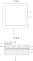
- the peripheral edge portion 101a is an outer portion of the surface of both surfaces of the positive electrode lead layer 101 on the side facing the positive active material layer 103, and has a frame shape. Even when the adhesive layer 140 disposed on the surface of both surfaces of the positive electrode lead layer 101 on the side facing the positive active material layer 103 covers a part of the frame-like peripheral edge portion 101a, the above effect is exhibited. However, it is more preferable that the entire frame-like peripheral edge portion 101a is covered, so that the above effect is further exhibited, and the battery performance is extremely less likely to deteriorate. That is, it is more preferable that the adhesive layer 140 disposed on the surface of both surfaces of the positive electrode lead layer 101 on the side facing the positive active material layer 103 may have a frame shape as illustrated in FIG. 5 . In FIG. 5 , the positive active material layer 103 is not illustrated.
- the adhesive layer 140 covering the peripheral edge portion 101a may be integrated with the adhesive layer 140 disposed between the one surface of the substrate 111 and the positive electrode lead layer 101. That is, the end portion of the adhesive layer 140, disposed between the one surface of the substrate 111 and the positive electrode lead layer 101, on the peripheral edge portion 101a side may extend to the peripheral edge portion 101a.
- the adhesive layer 140 covering the peripheral edge portion 101a may not be continuous with the adhesive layer 140 disposed between the one surface of the substrate 111 and the positive electrode lead layer 101 and may be separated.
- a bipolar lead-acid battery of a third embodiment will be described in detail with reference to FIG. 6 .
- the configuration and effects of the bipolar lead-acid battery of the third embodiment are substantially the same as those of the second embodiment, only the different parts will be described, and the description of the same parts will be omitted.
- the adhesive layer 140 covers the peripheral edge portion 101a of the surface of both surfaces of the positive electrode lead layer 101 on the side facing the positive active material layer 103.
- a covering member 150 is further disposed on the adhesive layer 140 covering the peripheral edge portion 101a. The covering member 150 is fixed to the substrate 111 with the adhesive layer 140 interposed therebetween. At this time, it is more preferable that the covering member 150 is disposed so as to press the positive electrode lead layer 101.
- the covering member 150 may be resistant to sulfuric acid and resistant to corrosion caused by the sulfuric acid, and examples of materials for the covering member 150 include sulfuric acid resistant resins, metals (for example, stainless steel), and ceramics.
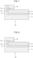
- a bipolar lead-acid battery of a fourth embodiment will be described in detail with reference to FIG. 7 .
- the configuration and effects of the bipolar lead-acid battery of the fourth embodiment are substantially the same as those of the third embodiment, only the different parts will be described, and the description of the same parts will be omitted.
- the substrate 111 has a flat plate shape, but in the fourth embodiment, the substrate 111 has a shape having a flange-like frame 170 at a peripheral edge tip end. That is, as illustrated in FIG. 7 , a plate-like portion extends from the peripheral edge tip end of the substrate 111 in a direction perpendicular to the one surface and the other surface of the substrate 111, and this plate-like portion is the frame 170. Therefore, the frame 170 is disposed so as to surround a peripheral edge tip end 101b of the positive electrode lead layer 101. In addition, the frame 170 is formed of a resin.
- the covering member 150 is fixed to frame 170 with the adhesive layer 140 interposed therebetween. Therefore, it is easy to dispose the covering member 150 so as to press the positive electrode lead layer 101. When the covering member 150 is disposed so as to press the positive electrode lead layer 101, the growth of the film 160 of the corrosion product to the peripheral edge portion 101a is further suppressed.
- the covering member 150 and the frame 170 can be fixed by an adhesive layer formed of an adhesive.
- the adhesive layer that fixes the covering member 150 and the frame 170 and the adhesive layer 140 that bonds the substrate 111 and the positive electrode lead layer 101 may be integrated as illustrated in FIG. 7 or may be separated.
- the frame 170 and the substrate 111 may be an integrated member or may be separate members.
- a bipolar lead-acid battery of a fifth embodiment will be described in detail with reference to FIG. 8 .
- the configuration and effects of the bipolar lead-acid battery of the fifth embodiment are substantially the same as those of the fourth embodiment, only the different parts will be described, and the description of the same parts will be omitted.
- the covering member 150 is a member separate from the frame 170, but in the fifth embodiment, the covering member 150 is a member integrated with the frame 170. Therefore, the covering member 150 is formed of the same resin as the frame 170. With such a configuration, it is easier to dispose the covering member 150 so as to press the positive electrode lead layer 101.
- a plate-like member formed of ABS resin that can be used as the substrate 111, and a foil-like member formed of lead that can also be used as the positive electrode lead layer 101 were bonded using various adhesives to produce test pieces, and a test was conducted to evaluate the sulfuric acid resistance of each test piece. That is, after heating sulfuric acid with a concentration of 38% by mass to 60°C and immersing the test piece in the sulfuric acid for one week, two weeks, and four weeks, the bonding state of the test piece was observed, and the peeling strength when the foil-like member formed of lead was peeled off from the plate-like member formed of ABS resin was measured.
- the coefficient of thermal expansion of the cured product of the adhesive was measured using a thermomechanical analyzer (TMA) manufactured by METTLER TOLEDO.
- TMA thermomechanical analyzer
- the measurement conditions are an applied load of 0.05N, a temperature range of -50°C to 150°C, and a temperature increase rate of 10°C/min.
- the sample has a length of 20 mm, a width of 2 mm, and a thickness of 0.1 mm.
- a tension method with a gauge length of 10 mm
- a compression method may be used in a case where the sample is small.
- the temperature range for measurement is preferable to be equal to or higher than the operating temperature range of the bipolar lead-acid battery.
- ⁇ L represents the amount of thermal expansion (mm)
- ⁇ represents the coefficient of thermal expansion (ppm)
- T1 represents the temperature (°C) before change
- T2 represents the temperature (°C) after change
- L represents the length of the sample (mm).
- the dynamic viscoelasticity of the cured product of the adhesive was measured using a dynamic viscoelasticity measuring device (DMA), trade name RSA-G2, manufactured by TA Instruments, and the glass transition temperature was measured from the tan ⁇ peak.
- the measurement conditions were a temperature range of -50°C to 150°C, a frequency of 1 Hz, a gauge length of 20 mm, a strain amount of 0.2%, and a temperature increase rate of 5°C/min, and the measurement was performed by the tension method.
- the results are shown in Table 1. Since the operating temperature range of the bipolar lead-acid battery is -15°C to 60°C, the glass transition temperature is preferably 60°C or higher.
- a test for evaluating the sulfuric acid resistance of the test piece, and the measurement of the coefficient of thermal expansion and the dynamic viscoelasticity of the cured product of the adhesive were performed after confirming the degree of curing of the cured product of the adhesive using a Fourier transform infrared spectrophotometer. Description will be made below.
- ATR method attenuated total reflection method
- a Fourier transform infrared spectrophotometer 660 or 610 manufactured by Agilent Technologies, Inc. the reaction rate of the epoxy group of the cured product of the adhesive was measured and the degree of curing of the cured product of the adhesive was thus obtained.
- a diamond was used as a crystal for the ATR method, and a silver-cadmium-tellurium compound (MCT) detector was used as a detector.
- the measurement conditions were a scanning rate of 25 kHz, an incident angle of 45 degrees, and a resolution of 4 cm -1 .
- the intensity of the absorption peak (913 cm -1 ) of the CO stretching vibration of the epoxy group and the intensity of the absorption peak (1508 cm -1 ) of the CC stretching vibration of the phenyl group were obtained, and from the ratio of these intensities ([intensity at 913 cm -1 ]/[[intensity at 1508 cm -1 ]), the degree of curing of the cured product of the adhesive was obtained. Then, the test for evaluating the sulfuric acid resistance of the test piece, and the measurement of the coefficient of thermal expansion and the dynamic viscoelasticity of the cured product of the adhesive were performed after confirming that the degree of curing was 0.15 or less and the cured product was sufficiently cured.
- a main agent K-9487A contains a bisphenol A type epoxy resin, and the content of the epoxy resin in the main agent is 80% to 90% by mass.
- a curing agent K-9487B contains a modified aromatic polyamine compound and 4,4'-methylenedianiline, the content of the modified aromatic polyamine compound in the curing agent is 65% to 75% by mass, and the content of 4,4'-methylenedianiline is 25% to 35% by mass.
- the mixing ratio of the main agent and the curing agent is 44 parts by mass of the curing agent with respect to 100 parts by mass of the main agent.
- a main agent XNR3114 contains a bisphenol A type epoxy resin and para-tertiary butyl phenyl glycidyl ether, the content of the epoxy resin in the main agent is 80% to 90% by mass, and the content of para-tertiary butyl phenyl glycidyl ether is 10% to 20% by mass.
- a curing agent XNH3114 contains a modified aliphatic polyamine compound, nonylphenol, m-xylylenediamine, triethylenetetramine, and isophoronediamine.
- the content of the modified aliphatic polyamine compound in the curing agent is 32% by mass
- the content of nonylphenol is 7.4% by mass
- the content of m-xylylenediamine is 11% by mass
- the content of triethylenetetramine is 15% by mass
- the content of isophoronediamine is 35% by mass.
- the mixing ratio of the main agent and the curing agent is 25 parts by mass of the curing agent with respect to 100 parts by mass of the main agent.
- a main agent XNR3106 contains a bisphenol A type epoxy resin, a bisphenol F type epoxy resin, and para-tertiary butyl phenyl glycidyl ether.
- the content of the bisphenol A type epoxy resin in the main agent is 40% to 50% by mass
- the content of the bisphenol F type epoxy resin is 30% to 40% by mass
- the content of para-tertiary butyl phenyl glycidyl ether is 10% to 20% by mass.
- a curing agent XNH3103 contains a modified polyamine compound, phenol, nonylphenol, m-xylylenediamine, triethylenetetramine, and isophoronediamine.
- the content of the modified polyamine compound in the curing agent is 25% by mass, the content of phenol is 4% by mass, the content of nonylphenol is 11% by mass, the content of m-xylylenediamine is 11% by mass, the content of triethylenetetramine is 23% by mass, and the content of isophoronediamine is 26% by mass.
- the mixing ratio of the main agent and the curing agent is 25 parts by mass of the curing agent with respect to 100 parts by mass of the main agent.
- Amain agent AV138 contains a bisphenol A type epoxy resin, a bisphenol F type epoxy resin, and silica.
- a curing agent HV998 contains a polyamidoamine compound and diethylenetriamine.
- the mixing ratio of the main agent and the curing agent is 40 parts by mass of the curing agent with respect to 100 parts by mass of the main agent.
- a main agent EPOTACK (trade name) AD-45 contains a bisphenol A type epoxy resin and crystalline silica.
- a curing agent PELCURE (trade name) HQ-1W contains an aliphatic polyamine compound, triethylenetetramine, and titanium dioxide.
- the mixing ratio of the main agent and the curing agent is 30 to 70 parts by mass of the curing agent with respect to 100 parts by mass of the main agent.
- the main agent contains a bisphenol A type epoxy resin, and the curing agent contains a polyamidoamine compound.
- the mixing ratio of the main agent and the curing agent is 100 parts by mass of the curing agent by mass with respect to 100 parts by mass of the main agent.
- the adhesive is a one component type adhesive containing acrylic-modified silicone.
- the bonding state of the test piece after immersion in the sulfuric acid for one week was observed, the sulfuric acid did not infiltrate into the interface between the foil-like member formed of lead and the adhesive layer, and the bonding state was poor. Further, when the peeling strength was measured, the interface between the plate-like member formed of ABS resin and the adhesive layer was peeled off, and the peeling strength was significantly reduced by immersion in the sulfuric acid. Further, when the bonding state of the test piece after immersion in the sulfuric acid for four weeks was observed, the bonding between the foil-like member formed of lead and the adhesive layer was not maintained.
- the pressure sensitive adhesive used in the double-sided pressure sensitive adhesive tape is an acrylic pressure sensitive adhesive.
Landscapes
- Chemical & Material Sciences (AREA)
- Chemical Kinetics & Catalysis (AREA)
- Electrochemistry (AREA)
- General Chemical & Material Sciences (AREA)
- Engineering & Computer Science (AREA)
- Manufacturing & Machinery (AREA)
- Inorganic Chemistry (AREA)
- Materials Engineering (AREA)
- Cell Electrode Carriers And Collectors (AREA)
- Sealing Battery Cases Or Jackets (AREA)
- Secondary Cells (AREA)
- Battery Electrode And Active Subsutance (AREA)
- Saccharide Compounds (AREA)
Abstract
Description
- The present invention relates to a bipolar lead-acid battery.
- A bipolar lead-acid battery includes a bipolar electrode having a positive electrode formed on one surface and a negative electrode formed on the other surface. As illustrated in
FIG. 9A , a positive electrode of a conventional bipolar electrode includes a positiveelectrode lead layer 220 disposed on one surface of asubstrate 210 formed of a resin with anadhesive layer 240 interposed therebetween, and a positive active material [PAM] layer (not illustrated) disposed on the positiveelectrode lead layer 220. - PTL 1:
WO 2013/073420 - In the bipolar lead-acid battery as described above, the positive
electrode lead layer 220 is corroded by the sulfuric acid contained in the electrolyte to form afilm 260 of a corrosion product (lead oxide) on the surface of the positive electrode lead layer 220 (refer toFIG. 9B ), and there is a risk that the growth of thefilm 260 of the corrosion product causes elongation (growth) of the positiveelectrode lead layer 220. Then, there is a risk that the positiveelectrode lead layer 220 and theadhesive layer 240 are peeled off by the growth, and the electrolyte infiltrates into the interface between the positiveelectrode lead layer 220 and theadhesive layer 240 to cause further progression of corrosion of the positiveelectrode lead layer 220 by the sulfuric acid (refer toFIG. 9C ). As a result, when the corrosion reaches, for example, the back surface of the positive electrode lead layer 220 (the surface facing the substrate 210), a short circuit may occur or the like, and battery performance may deteriorate in some cases. - An obj ect of the present invention is to provide a bipolar lead-acid battery in which, even when growth occurs in a positive electrode lead layer due to corrosion caused by sulfuric acid contained in an electrolyte, the electrolyte is less likely to infiltrate into the interface between the positive electrode lead layer and an adhesive layer, and deterioration in battery performance is less likely to occur.
- A bipolar lead-acid battery according to an aspect of the present invention is a bipolar lead-acid battery including a bipolar electrode having a positive electrode formed on one surface of a substrate and a negative electrode formed on the other surface, in which the positive electrode includes a positive electrode lead layer that is formed of lead or lead alloy and disposed on the one surface of the substrate, a positive active material layer that is disposed on the positive electrode lead layer, and an adhesive layer that is disposed between the one surface of the substrate and the positive electrode lead layer and bonds the one surface of the substrate and the positive electrode lead layer, the substrate is formed of a thermoplastic resin, the adhesive layer is formed of a cured product of a reaction-curing type adhesive that is cured by a reaction between a main agent containing an epoxy resin and a curing agent containing an amine compound, and even in a case where the adhesive layer is immersed in a sulfuric acid with a concentration of 38% by mass at a temperature of 60°C for four weeks, the sulfuric acid does not infiltrate into an interface between the positive electrode lead layer and the adhesive layer.
- According to the present invention, even when growth occurs in a positive electrode lead layer due to corrosion caused by a sulfuric acid contained in an electrolyte, the electrolyte is less likely to infiltrate into the interface between the positive electrode lead layer and an adhesive layer, and deterioration in battery performance is less likely to occur.
-
-
FIG. 1 is a cross-sectional view illustrating the structure of a first embodiment of a bipolar lead-acid battery according to the present invention; -
FIG. 2 is an enlarged cross-sectional view of a bipolar electrode for describing the structure of the main part of the bipolar lead-acid battery inFIG. 1 ; -
FIGS. 3A and 3B are explanatory diagrams illustrating a state in which even when growth occurs in a positive electrode lead layer due to corrosion caused by a sulfuric acid contained in an electrolyte in the bipolar lead-acid battery inFIG. 1 , the electrolyte is prevented from infiltrating into an interface between the positive electrode lead layer and an adhesive layer; -
FIG. 4 is an enlarged cross-sectional view of the bipolar electrode for explaining the structure of the main part of a second embodiment of the bipolar lead-acid battery according to the present invention; -
FIG. 5 is a plan view of the bipolar electrode for explaining the structure of the main part of the bipolar lead-acid battery inFIG. 4 ; -
FIG. 6 is an enlarged cross-sectional view of the bipolar electrode for explaining the structure of the main part of a third embodiment of the bipolar lead-acid battery according to the present invention; -
FIG. 7 is an enlarged cross-sectional view of the bipolar electrode for explaining the structure of the main part of a fourth embodiment of the bipolar lead-acid battery according to the present invention; -
FIG. 8 is an enlarged cross-sectional view of the bipolar electrode for explaining the structure of the main part of a fifth embodiment of the bipolar lead-acid battery according to the present invention; and -
FIGS. 9A, 9B, and 9C are explanatory diagrams illustrating a state in which as a result of growth occurring in a positive electrode lead layer due to corrosion caused by a sulfuric acid contained in an electrolyte in a conventional bipolar lead-acid battery, the electrolyte infiltrates into an interface between the positive electrode lead layer and an adhesive layer. - An embodiment of the present invention will be described. The embodiments described below show an example of the present invention. In addition, various changes or improvements can be applied to the present embodiment, and forms to which such changes or improvements are applied can also be included in the present invention.
- The structure of the bipolar lead-
acid battery 1 of the first embodiment will be described with reference toFIGS. 1 and 2 . The bipolar lead-acid battery 1 illustrated inFIG. 1 includes a first plate unit in which anegative electrode 110 is fixed to a flat plate-likefirst plate 11, a second plate unit in which anelectrolytic layer 105 is fixed inside a frame plate-likesecond plate 12, a third plate unit in which abipolar electrode 130 having apositive electrode 120 formed on one surface of asubstrate 111 and thenegative electrode 110 formed on the other surface is fixed inside a frame plate-likethird plate 13, and a fourth plate unit in which thepositive electrode 120 is fixed to a flat plate-likefourth plate 14. Thesubstrate 111 is formed of a thermoplastic resin. - By alternately laminating the second plate unit and the third plate unit between the first plate unit and the fourth plate unit, the bipolar lead-
acid battery 1 having a substantially rectangular parallelepiped shape is configured. The number of each of the second plate unit and the third plate unit to be laminated is set such that the storage capacity of the bipolar lead-acid battery 1 is set to have a desired numerical value. - A
negative electrode terminal 107 is fixed to thefirst plate 11, and thenegative electrode 110 fixed to thefirst plate 11 and thenegative electrode terminal 107 are electrically connected. - A
positive electrode terminal 108 is fixed to thefourth plate 14, and thepositive electrode 120 fixed to thefourth plate 14 and thepositive electrode terminal 108 are electrically connected. - The
electrolytic layer 105 is formed of, for example, a glass fiber mat impregnated with an electrolyte containing sulfuric acid. - The first to
fourth plates fourth plates - The
positive electrode 120 includes a positiveelectrode lead layer 101 that is formed of lead or lead alloy and is disposed on the one surface of thesubstrate 111, a positiveactive material layer 103 that is disposed on the positiveelectrode lead layer 101, and anadhesive layer 140 that is disposed between the one surface of thesubstrate 111 and the positiveelectrode lead layer 101 and bonds the one surface of thesubstrate 111 and the positiveelectrode lead layer 101. That is, theadhesive layer 140, the positiveelectrode lead layer 101, and the positiveactive material layer 103 are laminated in this order on the one surface of the substrate 111 (the surface facing upward in the paper plane inFIGS. 2 ,3A, and 3B ) . - The
negative electrode 110 includes a negativeelectrode lead layer 102 that is formed of lead or lead alloy and is disposed on the other surface of thesubstrate 111, a negative active material [NAM]layer 104 that is disposed on the negativeelectrode lead layer 102, and an adhesive layer (not illustrated) that is disposed between the other surface of thesubstrate 111 and the negativeelectrode lead layer 102 and bonds the other surface of thesubstrate 111 and the negativeelectrode lead layer 102. - The
positive electrode 120 and thenegative electrode 110 are electrically connected by an appropriate method. - The
negative electrode 110 and the positiveactive material layer 103 are not illustrated in cross-sectional views of the bipolar electrode inFIGS. 2 ,3A, and 3B and the subsequent drawings. - In the bipolar lead-
acid battery 1 of the first embodiment having such a configuration, as described above, thesubstrate 111, the positiveelectrode lead layer 101, the positiveactive material layer 103, the negativeelectrode lead layer 102, and the negativeactive material layer 104 constitutes thebipolar electrode 130. The bipolar electrode is a single electrode that functions as both a positive electrode and a negative electrode. - The bipolar lead-
acid battery 1 of the first embodiment has a battery configuration in which a plurality of cell members each formed with theelectrolytic layer 105 interposed between thepositive electrode 120 and thenegative electrode 110 are alternately laminated and assembled so that the cell members are disposed in series. - Further, in the bipolar lead-
acid battery 1 of the first embodiment, theadhesive layer 140 disposed between the one surface of thesubstrate 111 and the positiveelectrode lead layer 101 is formed of a cured product of a reaction-curing type adhesive that is cured by a reaction between a main agent containing an epoxy resin and a curing agent containing an amine compound. - Since this cured product is resistant to sulfuric acid (hereinafter, a property of being resistant to sulfuric acid may be referred to as "sulfuric acid resistance"), and the sulfuric acid does not infiltrate into the interface between the positive
electrode lead layer 101 and theadhesive layer 140 even in a case where theadhesive layer 140 is immersed in the sulfuric acid with a concentration of 38% by mass at a temperature of 60°C for four weeks, the cured product is less likely to decompose, deteriorate, corrode, or the like even when the cured product comes in contact with the electrolyte. Therefore, since the positiveelectrode lead layer 101 and theadhesive layer 140 are firmly bonded, even when growth occurs in the positiveelectrode lead layer 101 due to corrosion caused by a sulfuric acid contained in the electrolyte, the electrolyte is prevented from infiltrating into the interface between the positiveelectrode lead layer 101 and theadhesive layer 140. - As described in more detail with reference to
FIGS. 3A and 3B , since theadhesive layer 140 is resistant to the sulfuric acid, the positiveelectrode lead layer 101 and theadhesive layer 140 are firmly bonded inFIG. 3A . Therefore, as illustrated inFIG. 3B , even when afilm 160 of a corrosion product (lead oxide) is formed on the surface of the positiveelectrode lead layer 101, the growth of thefilm 160 of the corrosion product is suppressed by theadhesive layer 140 to prevent thefilm 160 of the corrosion product from infiltrating into the interface between the positiveelectrode lead layer 101 and theadhesive layer 140. - As a result, even when growth occurs in the positive
electrode lead layer 101 due to corrosion caused by the sulfuric acid contained in the electrolyte, the positiveelectrode lead layer 101 and theadhesive layer 140 are less likely to be peeled off, and thus the electrolyte is prevented from infiltrating into the interface between the positiveelectrode lead layer 101 and theadhesive layer 140. Therefore, it is difficult for the corrosion caused by sulfuric acid to reach the back surface of the positive electrode lead layer 101 (the surface facing the substrate 111) to cause a short circuit or the like and cause a defect of deterioration in battery performance. - Examples of the thermoplastic resin forming the
substrate 111 include an acrylonitrile-butadiene-styrene copolymer (ABS resin) and polypropylene. These thermoplastic resins have excellent moldability and excellent sulfuric acid resistance. Therefore, even when the electrolyte comes into contact with thesubstrate 111, thesubstrate 111 is less likely to decompose, deteriorate, corrode, or the like. - Although the
adhesive layer 140 is formed of a cured product obtained by curing a reaction-curing type adhesive, the reaction-curing type adhesive is a type of adhesive that is cured by mixing a main agent containing an epoxy resin and a curing agent containing an amine compound, and allowing a reaction between the main agent and the curing agent. Since such a reaction-curing type adhesive can be cured at room temperature (for example, 20°C or higher and 40°C or lower), the reaction-curing type adhesive can be cured at a temperature that does not easily affect the metal composition of the lead or lead alloy forming the positiveelectrode lead layer 101 and the negativeelectrode lead layer 102. Further, the reaction-curing type adhesive is less likely to adversely affect the thermoplastic resin forming thesubstrate 111. Further, the reaction-curing type adhesive has advantages such as high adhesiveness, long working life, and the like. It is preferable that the mixing ratio of the main agent and the curing agent in the reaction-curing type adhesive is 44 parts by mass or less of the curing agent with respect to 100 parts by mass of the main agent. - As the epoxy resin contained in the main agent, for example, at least one of a bisphenol A type epoxy resin and a bisphenol F type epoxy resin may be used. These epoxy resins may be used alone or in combination of two or more thereof.
- Examples of the amine compound to be contained in the curing agent include an aliphatic polyamine compound, an alicyclic polyamine compound, and an aromatic polyamine compound. These amine compounds may be used alone or in combination of two or more thereof.
- Specific examples of the aliphatic polyamine compound include aliphatic primary amines such as triethylenetetramine (C6H18N4) and the like, and aliphatic secondary amines such as triethylenetetramine and the like. Specific examples of the alicyclic polyamine compound include alicyclic primary amines such as isophoronediamine (C10H22N2) and the like. Specific examples of the aromatic polyamine compound include aromatic primary amines such as diaminodiphenylmethane (C13H14N2) and the like.
- A bipolar lead-acid battery of a second embodiment will be described in detail with reference to
FIG. 4 . However, since the configuration and effects of the bipolar lead-acid battery of the second embodiment are substantially the same as those of the first embodiment, only the different parts will be described, and the description of the same parts will be omitted. - In the first embodiment, the
adhesive layer 140 is disposed between the one surface of thesubstrate 111 and the positive electrode lead layer 101 (that is, on a surface of both surfaces of the positiveelectrode lead layer 101 on a side facing the substrate 111), and is not disposed on a surface of both surfaces of the positiveelectrode lead layer 101 on a side facing the positiveactive material layer 103. On the other hand, in the second embodiment, as illustrated inFIG. 4 , theadhesive layer 140 extends from between thesubstrate 111 and the positiveelectrode lead layer 101 to aperipheral edge portion 101a of the surface of both surfaces of the positiveelectrode lead layer 101 on the side facing the positiveactive material layer 103, and comes into close contact with theperipheral edge portion 101a to cover theperipheral edge portion 101a. - In such a bipolar lead-acid battery of the second embodiment, since the
adhesive layer 140 covers theperipheral edge portion 101a of the surface of both surfaces of the positiveelectrode lead layer 101 on the side facing the positiveactive material layer 103, even when growth occurs in the positiveelectrode lead layer 101 due to corrosion caused by the sulfuric acid contained in the electrolyte, the electrolyte is prevented from infiltrating into the interface between the positiveelectrode lead layer 101 and theadhesive layer 140. - The
peripheral edge portion 101a is an outer portion of the surface of both surfaces of the positiveelectrode lead layer 101 on the side facing the positiveactive material layer 103, and has a frame shape. Even when theadhesive layer 140 disposed on the surface of both surfaces of the positiveelectrode lead layer 101 on the side facing the positiveactive material layer 103 covers a part of the frame-likeperipheral edge portion 101a, the above effect is exhibited. However, it is more preferable that the entire frame-likeperipheral edge portion 101a is covered, so that the above effect is further exhibited, and the battery performance is extremely less likely to deteriorate. That is, it is more preferable that theadhesive layer 140 disposed on the surface of both surfaces of the positiveelectrode lead layer 101 on the side facing the positiveactive material layer 103 may have a frame shape as illustrated inFIG. 5 . InFIG. 5 , the positiveactive material layer 103 is not illustrated. - As illustrated in
FIG. 4 , theadhesive layer 140 covering theperipheral edge portion 101a may be integrated with theadhesive layer 140 disposed between the one surface of thesubstrate 111 and the positiveelectrode lead layer 101. That is, the end portion of theadhesive layer 140, disposed between the one surface of thesubstrate 111 and the positiveelectrode lead layer 101, on theperipheral edge portion 101a side may extend to theperipheral edge portion 101a. Of course, theadhesive layer 140 covering theperipheral edge portion 101a may not be continuous with theadhesive layer 140 disposed between the one surface of thesubstrate 111 and the positiveelectrode lead layer 101 and may be separated. - A bipolar lead-acid battery of a third embodiment will be described in detail with reference to
FIG. 6 . However, since the configuration and effects of the bipolar lead-acid battery of the third embodiment are substantially the same as those of the second embodiment, only the different parts will be described, and the description of the same parts will be omitted. - In the second embodiment, the
adhesive layer 140 covers theperipheral edge portion 101a of the surface of both surfaces of the positiveelectrode lead layer 101 on the side facing the positiveactive material layer 103. However, in the third embodiment, as illustrated inFIG. 6 , a coveringmember 150 is further disposed on theadhesive layer 140 covering theperipheral edge portion 101a. The coveringmember 150 is fixed to thesubstrate 111 with theadhesive layer 140 interposed therebetween. At this time, it is more preferable that the coveringmember 150 is disposed so as to press the positiveelectrode lead layer 101. - In such a bipolar lead-acid battery of the third embodiment, even when growth occurs in the positive
electrode lead layer 101 due to corrosion caused by the sulfuric acid contained in the electrolyte, the electrolyte is further prevented from infiltrating into the interface between the positiveelectrode lead layer 101 and theadhesive layer 140. - The covering
member 150 may be resistant to sulfuric acid and resistant to corrosion caused by the sulfuric acid, and examples of materials for the coveringmember 150 include sulfuric acid resistant resins, metals (for example, stainless steel), and ceramics. - A bipolar lead-acid battery of a fourth embodiment will be described in detail with reference to
FIG. 7 . However, since the configuration and effects of the bipolar lead-acid battery of the fourth embodiment are substantially the same as those of the third embodiment, only the different parts will be described, and the description of the same parts will be omitted. - In the third embodiment, the
substrate 111 has a flat plate shape, but in the fourth embodiment, thesubstrate 111 has a shape having a flange-like frame 170 at a peripheral edge tip end. That is, as illustrated inFIG. 7 , a plate-like portion extends from the peripheral edge tip end of thesubstrate 111 in a direction perpendicular to the one surface and the other surface of thesubstrate 111, and this plate-like portion is theframe 170. Therefore, theframe 170 is disposed so as to surround a peripheraledge tip end 101b of the positiveelectrode lead layer 101. In addition, theframe 170 is formed of a resin. - In the bipolar lead-acid battery of the fourth embodiment, the covering
member 150 is fixed to frame 170 with theadhesive layer 140 interposed therebetween. Therefore, it is easy to dispose the coveringmember 150 so as to press the positiveelectrode lead layer 101. When the coveringmember 150 is disposed so as to press the positiveelectrode lead layer 101, the growth of thefilm 160 of the corrosion product to theperipheral edge portion 101a is further suppressed. - The covering
member 150 and theframe 170 can be fixed by an adhesive layer formed of an adhesive. The adhesive layer that fixes the coveringmember 150 and theframe 170 and theadhesive layer 140 that bonds thesubstrate 111 and the positiveelectrode lead layer 101 may be integrated as illustrated inFIG. 7 or may be separated. - Further, as illustrated in
FIG. 7 , theframe 170 and thesubstrate 111 may be an integrated member or may be separate members. - A bipolar lead-acid battery of a fifth embodiment will be described in detail with reference to
FIG. 8 . However, since the configuration and effects of the bipolar lead-acid battery of the fifth embodiment are substantially the same as those of the fourth embodiment, only the different parts will be described, and the description of the same parts will be omitted. - In the fourth embodiment, the covering
member 150 is a member separate from theframe 170, but in the fifth embodiment, the coveringmember 150 is a member integrated with theframe 170. Therefore, the coveringmember 150 is formed of the same resin as theframe 170. With such a configuration, it is easier to dispose the coveringmember 150 so as to press the positiveelectrode lead layer 101. - In the bipolar lead storage batteries of the first to fifth embodiments, a plate-like member formed of ABS resin that can be used as the
substrate 111, and a foil-like member formed of lead that can also be used as the positiveelectrode lead layer 101 were bonded using various adhesives to produce test pieces, and a test was conducted to evaluate the sulfuric acid resistance of each test piece. That is, after heating sulfuric acid with a concentration of 38% by mass to 60°C and immersing the test piece in the sulfuric acid for one week, two weeks, and four weeks, the bonding state of the test piece was observed, and the peeling strength when the foil-like member formed of lead was peeled off from the plate-like member formed of ABS resin was measured. - In addition, the working life was evaluated for each adhesive. Further, the coefficient of thermal expansion and the dynamic viscoelasticity of the cured product of each adhesive were measured. The measuring method will be described below.
- The coefficient of thermal expansion of the cured product of the adhesive was measured using a thermomechanical analyzer (TMA) manufactured by METTLER TOLEDO. The measurement conditions are an applied load of 0.05N, a temperature range of -50°C to 150°C, and a temperature increase rate of 10°C/min. In addition, the sample has a length of 20 mm, a width of 2 mm, and a thickness of 0.1 mm. Although the measurement was performed by a tension method with a gauge length of 10 mm, a compression method may be used in a case where the sample is small.
- It is preferable to set the temperature range for measurement to be equal to or higher than the operating temperature range of the bipolar lead-acid battery. The coefficient of thermal expansion was obtained from the slope in a temperature range of -15°C to 60°C using the following equation. The results are shown in Table 1.

- In the above equation, ΔL represents the amount of thermal expansion (mm), α represents the coefficient of thermal expansion (ppm), T1 represents the temperature (°C) before change, T2 represents the temperature (°C) after change, and L represents the length of the sample (mm).
- When the coefficients of thermal expansion of the substrate, the adhesive layer, and the positive electrode lead layer are significantly different, strain is easily caused at the interface, and thus it is preferable to reduce the difference in coefficient of thermal expansion between the substrate, the adhesive layer, and the positive electrode lead layer.
- The dynamic viscoelasticity of the cured product of the adhesive was measured using a dynamic viscoelasticity measuring device (DMA), trade name RSA-G2, manufactured by TA Instruments, and the glass transition temperature was measured from the tan δ peak. The measurement conditions were a temperature range of -50°C to 150°C, a frequency of 1 Hz, a gauge length of 20 mm, a strain amount of 0.2%, and a temperature increase rate of 5°C/min, and the measurement was performed by the tension method. The results are shown in Table 1. Since the operating temperature range of the bipolar lead-acid battery is -15°C to 60°C, the glass transition temperature is preferably 60°C or higher.
- A test for evaluating the sulfuric acid resistance of the test piece, and the measurement of the coefficient of thermal expansion and the dynamic viscoelasticity of the cured product of the adhesive were performed after confirming the degree of curing of the cured product of the adhesive using a Fourier transform infrared spectrophotometer. Description will be made below. By an attenuated total reflection method (ATR method) using a Fourier transform infrared spectrophotometer 660 or 610 manufactured by Agilent Technologies, Inc., the reaction rate of the epoxy group of the cured product of the adhesive was measured and the degree of curing of the cured product of the adhesive was thus obtained.
- A diamond was used as a crystal for the ATR method, and a silver-cadmium-tellurium compound (MCT) detector was used as a detector. The measurement conditions were a scanning rate of 25 kHz, an incident angle of 45 degrees, and a resolution of 4 cm-1.
- From the obtained spectrum, the intensity of the absorption peak (913 cm-1) of the CO stretching vibration of the epoxy group and the intensity of the absorption peak (1508 cm-1) of the CC stretching vibration of the phenyl group were obtained, and from the ratio of these intensities ([intensity at 913 cm-1]/[[intensity at 1508 cm-1]), the degree of curing of the cured product of the adhesive was obtained. Then, the test for evaluating the sulfuric acid resistance of the test piece, and the measurement of the coefficient of thermal expansion and the dynamic viscoelasticity of the cured product of the adhesive were performed after confirming that the degree of curing was 0.15 or less and the cured product was sufficiently cured.
- Examples and Comparative Examples are described below.
- A main agent K-9487A contains a bisphenol A type epoxy resin, and the content of the epoxy resin in the main agent is 80% to 90% by mass. A curing agent K-9487B contains a modified aromatic polyamine compound and 4,4'-methylenedianiline, the content of the modified aromatic polyamine compound in the curing agent is 65% to 75% by mass, and the content of 4,4'-methylenedianiline is 25% to 35% by mass. In addition, the mixing ratio of the main agent and the curing agent is 44 parts by mass of the curing agent with respect to 100 parts by mass of the main agent.
- The working life of this adhesive at 25°C was 60 minutes, and the bonding work was easily performed.
- Further, when the bonding state of the test piece after immersion in the sulfuric acid for four weeks was observed, the sulfuric acid did not infiltrate into the interface between the foil-like member formed of lead and the adhesive layer, and the bonding state was good. Further, when the peeling strength was measured, it was found that the interface between the foil-like member formed of lead and the adhesive layer was peeled off, and there was almost no difference in peeling strength between before and after immersion in the sulfuric acid.
- A main agent XNR3114 contains a bisphenol A type epoxy resin and para-tertiary butyl phenyl glycidyl ether, the content of the epoxy resin in the main agent is 80% to 90% by mass, and the content of para-tertiary butyl phenyl glycidyl ether is 10% to 20% by mass.
- A curing agent XNH3114 contains a modified aliphatic polyamine compound, nonylphenol, m-xylylenediamine, triethylenetetramine, and isophoronediamine. The content of the modified aliphatic polyamine compound in the curing agent is 32% by mass, the content of nonylphenol is 7.4% by mass, the content of m-xylylenediamine is 11% by mass, and the content of triethylenetetramine is 15% by mass, and the content of isophoronediamine is 35% by mass.
- The mixing ratio of the main agent and the curing agent is 25 parts by mass of the curing agent with respect to 100 parts by mass of the main agent.
- The working life of this adhesive at 25°C was 60 minutes, and the bonding work was easily performed.
- Further, when the bonding state of the test piece after immersion in the sulfuric acid for four weeks was observed, the sulfuric acid did not infiltrate into the interface between the foil-like member formed of lead and the adhesive layer, and the bonding state was good. Further, when the peeling strength was measured, it was found that the interface between the foil-like member formed of lead and the adhesive layer was peeled off, and there was almost no difference in peeling strength between before and after immersion in the sulfuric acid.
- A main agent XNR3106 contains a bisphenol A type epoxy resin, a bisphenol F type epoxy resin, and para-tertiary butyl phenyl glycidyl ether. The content of the bisphenol A type epoxy resin in the main agent is 40% to 50% by mass, the content of the bisphenol F type epoxy resin is 30% to 40% by mass, and the content of para-tertiary butyl phenyl glycidyl ether is 10% to 20% by mass.
- A curing agent XNH3103 contains a modified polyamine compound, phenol, nonylphenol, m-xylylenediamine, triethylenetetramine, and isophoronediamine. The content of the modified polyamine compound in the curing agent is 25% by mass, the content of phenol is 4% by mass, the content of nonylphenol is 11% by mass, the content of m-xylylenediamine is 11% by mass, the content of triethylenetetramine is 23% by mass, and the content of isophoronediamine is 26% by mass.
- The mixing ratio of the main agent and the curing agent is 25 parts by mass of the curing agent with respect to 100 parts by mass of the main agent.
- The working life of this adhesive at 25°C was 20 minutes, which was a short time for bonding work.
- Further, when the bonding state of the test piece after immersion in the sulfuric acid for four weeks was observed, the sulfuric acid did not infiltrate into the interface between the foil-like member formed of lead and the adhesive layer, and the bonding state was good. Further, when the peeling strength was measured, it was found that the interface between the foil-like member formed of lead and the adhesive layer was peeled off, and there was almost no difference in peeling strength between before and after immersion in the sulfuric acid.
- Amain agent AV138 contains a bisphenol A type epoxy resin, a bisphenol F type epoxy resin, and silica. A curing agent HV998 contains a polyamidoamine compound and diethylenetriamine.
- The mixing ratio of the main agent and the curing agent is 40 parts by mass of the curing agent with respect to 100 parts by mass of the main agent.
- The working life of this adhesive at 25°C was 35 minutes, which was a short time for bonding work.
- Further, when the bonding state of the test piece after immersion in the sulfuric acid for one week was observed, it was found that the adhesive layer interface was corroded by the sulfuric acid. Further, when the peeling strength was measured, the interface between the plate-like member formed of ABS resin and the adhesive layer was peeled off, and the peeling strength was significantly reduced by immersion in the sulfuric acid. Further, when the bonding state of the test piece after immersion in the sulfuric acid for four weeks was observed, the bonding between the foil-like member formed of lead and the adhesive layer was not maintained.
- A main agent EPOTACK (trade name) AD-45 contains a bisphenol A type epoxy resin and crystalline silica. A curing agent PELCURE (trade name) HQ-1W contains an aliphatic polyamine compound, triethylenetetramine, and titanium dioxide.
- The mixing ratio of the main agent and the curing agent is 30 to 70 parts by mass of the curing agent with respect to 100 parts by mass of the main agent.
- The working life of this adhesive at 25°C was 120 minutes, and the bonding work was easily performed.
- Further, when the bonding state of the test piece after immersion in the sulfuric acid for one week was observed, it was found that the adhesive layer interface was corroded by the sulfuric acid. Further, when the peeling strength was measured, the interface between the plate-like member formed of ABS resin and the adhesive layer was peeled off, and the peeling strength was significantly reduced by immersion in the sulfuric acid. Further, when the bonding state of the test piece after immersion in the sulfuric acid for four weeks was observed, the bonding between the foil-like member formed of lead and the adhesive layer was not maintained.
- The main agent contains a bisphenol A type epoxy resin, and the curing agent contains a polyamidoamine compound.
- In addition, the mixing ratio of the main agent and the curing agent is 100 parts by mass of the curing agent by mass with respect to 100 parts by mass of the main agent.
- The working life of this adhesive at 25°C was 60 minutes, and the bonding work was easily performed.
- Further, when the bonding state of the test piece after immersion in the sulfuric acid for one week was observed, it was found that the adhesive layer interface was corroded by the sulfuric acid. Further, when the peeling strength was measured, the interface between the plate-like member formed of ABS resin and the adhesive layer was peeled off, and the peeling strength was significantly reduced by immersion in the sulfuric acid.
- Further, when the bonding state of the test piece after immersion in the sulfuric acid for four weeks was observed, the bonding between the foil-like member formed of lead and the adhesive layer was not maintained.
- The adhesive is a one component type adhesive containing acrylic-modified silicone.
- The working life of this adhesive at 25°C was 2 minutes, and the bonding work was less likely to be performed.
- Further, when the bonding state of the test piece after immersion in the sulfuric acid for one week was observed, the sulfuric acid did not infiltrate into the interface between the foil-like member formed of lead and the adhesive layer, and the bonding state was poor. Further, when the peeling strength was measured, the interface between the plate-like member formed of ABS resin and the adhesive layer was peeled off, and the peeling strength was significantly reduced by immersion in the sulfuric acid. Further, when the bonding state of the test piece after immersion in the sulfuric acid for four weeks was observed, the bonding between the foil-like member formed of lead and the adhesive layer was not maintained.
- The pressure sensitive adhesive used in the double-sided pressure sensitive adhesive tape is an acrylic pressure sensitive adhesive.
- When the bonding state of the test piece after immersion in the sulfuric acid for one week was observed, it was found that the sulfuric acid infiltrated into the interface between the foil-like member formed of lead and the pressure sensitive adhesive layer to cause the pressure sensitive adhesive layer to swell, the interface between the foil-like member formed of lead and the pressure sensitive adhesive layer was peeled off, and the bonding between the foil-like member formed of lead and the pressure sensitive adhesive layer was not maintained.
[Table 1] Unit Ex. 1 Ex. 2 Ex. 3 Com. Ex. 1 Com. Ex. 2 Com. Ex. 3 Com. Ex. 4 Com. Ex. 5 Main agent K-9487A XNR3114 XNR3106 AV138 AD-45 1500 X8008 Double-sided tape Curing agent K-9487B XNH3114 XNH3103 HV998 HQ-1W 1500 - - Coefficient of thermal expansion ppm/K 98 71 98 71 118 238 74 - Glass transition temperature °C 86 89 81 98 80 64 -48 8 -
- 1
- bipolar lead-acid battery
- 101
- positive electrode lead layer
- 101a
- peripheral edge portion
- 101b
- peripheral edge tip end
- 102
- negative electrode lead layer
- 103
- positive active material layer
- 104
- negative active material layer
- 105
- electrolytic layer
- 110
- negative electrode
- 111
- substrate
- 120
- positive electrode
- 130
- bipolar electrode
- 140
- adhesive layer
- 150
- covering member
- 170
- frame
Claims (6)
- A bipolar lead-acid battery comprising:a bipolar electrode having a positive electrode formed on one surface of a substrate and a negative electrode formed on the other surface,wherein the positive electrode includes a positive electrode lead layer that is formed of lead or lead alloy and disposed on the one surface of the substrate, a positive active material layer that is disposed on the positive electrode lead layer, and an adhesive layer that is disposed between the one surface of the substrate and the positive electrode lead layer and bonds the one surface of the substrate and the positive electrode lead layer,the substrate is formed of a thermoplastic resin,the adhesive layer is formed of a cured product of a reaction-curing type adhesive that is cured by a reaction between a main agent containing an epoxy resin and a curing agent containing an amine compound, andeven in a case where the adhesive layer is immersed in a sulfuric acid with a concentration of 38% by mass at a temperature of 60°C for four weeks, the sulfuric acid does not infiltrate into an interface between the positive electrode lead layer and the adhesive layer.
- The bipolar lead-acid battery according to claim 1, wherein
the thermoplastic resin is anacrylonitrile-butadiene-styrene copolymer orpolypropylene. - The bipolar lead-acid battery according to claim 1 or 2, wherein
the epoxy resin is at least one of a bisphenol A type epoxy resin and a bisphenol F type epoxy resin. - The bipolar lead-acid battery according to any one of claims 1 to 3, wherein
the amine compound is at least one of an aliphatic polyamine compound, an alicyclic polyamine compound, and an aromatic polyamine compound. - The bipolar lead-acid battery according to any one of claims 1 to 4, wherein
a mixing ratio of the main agent and the curing agent in the reaction-curing type adhesive is 44 parts by mass or less of the curing agent with respect to 100 parts by mass of the main agent. - The bipolar lead-acid battery according to any one of claims 1 to 5, wherein
the adhesive layer extends to a peripheral edge portion of a surface of both surfaces of the positive electrode lead layer on a side facing the positive active material layer, and comes into close contact with the peripheral edge portion to cover the peripheral edge portion.
Applications Claiming Priority (2)
| Application Number | Priority Date | Filing Date | Title |
|---|---|---|---|
| JP2020165685 | 2020-09-30 | ||
| PCT/JP2021/032702 WO2022070791A1 (en) | 2020-09-30 | 2021-09-06 | Bipolar lead-acid battery |
Publications (2)
| Publication Number | Publication Date |
|---|---|
| EP4224569A1 true EP4224569A1 (en) | 2023-08-09 |
| EP4224569A4 EP4224569A4 (en) | 2025-06-25 |
Family
ID=80950334
Family Applications (1)
| Application Number | Title | Priority Date | Filing Date |
|---|---|---|---|
| EP21875093.3A Withdrawn EP4224569A4 (en) | 2020-09-30 | 2021-09-06 | Bipolar lead-acid battery |
Country Status (7)
| Country | Link |
|---|---|
| US (1) | US20230238654A1 (en) |
| EP (1) | EP4224569A4 (en) |
| JP (1) | JPWO2022070791A1 (en) |
| CN (1) | CN116250097A (en) |
| AU (1) | AU2021353160A1 (en) |
| BR (1) | BR112023004630A2 (en) |
| WO (1) | WO2022070791A1 (en) |
Family Cites Families (9)
| Publication number | Priority date | Publication date | Assignee | Title |
|---|---|---|---|---|
| US4510219A (en) * | 1983-11-14 | 1985-04-09 | California Institute Of Technology | Battery plate containing filler with conductive coating |
| US4513060A (en) * | 1984-02-08 | 1985-04-23 | E. I. Du Pont De Nemours And Company | Chlorosulfonated polyethylene coating composition |
| JP2585847B2 (en) * | 1990-07-27 | 1997-02-26 | 新神戸電機株式会社 | Thin sealed storage battery |
| MX9401371A (en) * | 1993-02-24 | 1994-08-31 | Trojan Battery Co | A CONSTRUCTION OF PLATE FOR ELECTRODE. |
| US5800946A (en) * | 1996-12-06 | 1998-09-01 | Grosvenor; Victor L. | Bipolar lead-acid battery plates |
| JP2001068115A (en) * | 1999-08-27 | 2001-03-16 | Hitachi Chem Co Ltd | Nonaqueous solvent binder composition, method of manufacturing electrode, electrode and nonaqueous solvent secondary battery |
| JP2005294024A (en) * | 2004-03-31 | 2005-10-20 | Ntt Data Ex Techno Corp | Coated collector for storage battery, its manufacturing method, and storage battery having coated collector |
| JP5374931B2 (en) * | 2008-06-18 | 2013-12-25 | 株式会社Gsユアサ | Lead-acid battery and manufacturing method thereof |
| CN104752673A (en) * | 2013-12-27 | 2015-07-01 | 松下蓄电池(沈阳)有限公司 | A lead storage battery |
-
2021
- 2021-09-06 BR BR112023004630A patent/BR112023004630A2/en not_active Application Discontinuation
- 2021-09-06 CN CN202180062043.0A patent/CN116250097A/en active Pending
- 2021-09-06 JP JP2022553727A patent/JPWO2022070791A1/ja active Pending
- 2021-09-06 WO PCT/JP2021/032702 patent/WO2022070791A1/en not_active Ceased
- 2021-09-06 AU AU2021353160A patent/AU2021353160A1/en not_active Abandoned
- 2021-09-06 EP EP21875093.3A patent/EP4224569A4/en not_active Withdrawn
-
2023
- 2023-03-27 US US18/190,690 patent/US20230238654A1/en not_active Abandoned
Also Published As
| Publication number | Publication date |
|---|---|
| AU2021353160A9 (en) | 2025-03-20 |
| JPWO2022070791A1 (en) | 2022-04-07 |
| WO2022070791A1 (en) | 2022-04-07 |
| US20230238654A1 (en) | 2023-07-27 |
| EP4224569A4 (en) | 2025-06-25 |
| CN116250097A (en) | 2023-06-09 |
| AU2021353160A1 (en) | 2023-06-08 |
| BR112023004630A2 (en) | 2023-04-11 |
Similar Documents
| Publication | Publication Date | Title |
|---|---|---|
| US11482747B2 (en) | Pouch-type secondary battery | |
| US9123835B2 (en) | Connected structure and method for manufacture thereof | |
| EP2958161B1 (en) | Power-cell packaging material | |
| US11990420B2 (en) | Electromagnetic wave shielding sheet | |
| KR101874900B1 (en) | Cell pouch and method of preparing the same | |
| CN103326045B (en) | Fuel cell separator, fuel cell, and method for manufacturing fuel cell separator | |
| KR20240111002A (en) | Battery module and battery pack | |
| EP3267506B1 (en) | Outer packaging material for electricity storage device and electricity storage device using same | |
| TW531960B (en) | SAW device and method of manufacturing the device | |
| EP4354522A1 (en) | Resin film for current collecting sheet, current collecting sheet, solar cell element with current collecting sheet, and solar cell | |
| EP2860793A1 (en) | Laminated thin film battery | |
| JP2004022543A (en) | Galvanic battery | |
| EP4362175A1 (en) | Exterior material for power storage device | |
| US20230238654A1 (en) | Bipolar Lead-Acid Battery | |
| KR102069637B1 (en) | Heat radiation sheet and EMI shielding-Heat radiation composite sheet comprising the same | |
| WO2022158096A1 (en) | Bipolar storage battery | |
| US20240047697A1 (en) | Lead Foil And Bipolar Lead Acid Storage Battery | |
| WO2022070829A1 (en) | Bipolar storage battery | |
| CN218471965U (en) | Flexible photovoltaic module | |
| EP4206358A1 (en) | A stainless steel surface treatment method for bonding with a polymer | |
| KR102191344B1 (en) | Heat radiation sheet and EMI shielding-Heat radiation composite sheet comprising the same | |
| KR102437590B1 (en) | Heat radiation sheet and EMI shielding-Heat radiation composite sheet comprising the same | |
| JP2014067689A (en) | Fuel battery | |
| JP6222816B2 (en) | Surface protection film for chemical polishing treatment | |
| CN113185929A (en) | Conductive composite adhesive tape |
Legal Events
| Date | Code | Title | Description |
|---|---|---|---|
| STAA | Information on the status of an ep patent application or granted ep patent |
Free format text: STATUS: THE INTERNATIONAL PUBLICATION HAS BEEN MADE |
|
| PUAI | Public reference made under article 153(3) epc to a published international application that has entered the european phase |
Free format text: ORIGINAL CODE: 0009012 |
|
| STAA | Information on the status of an ep patent application or granted ep patent |
Free format text: STATUS: REQUEST FOR EXAMINATION WAS MADE |
|
| 17P | Request for examination filed |
Effective date: 20230315 |
|
| AK | Designated contracting states |
Kind code of ref document: A1 Designated state(s): AL AT BE BG CH CY CZ DE DK EE ES FI FR GB GR HR HU IE IS IT LI LT LU LV MC MK MT NL NO PL PT RO RS SE SI SK SM TR |
|
| DAV | Request for validation of the european patent (deleted) | ||
| DAX | Request for extension of the european patent (deleted) | ||
| A4 | Supplementary search report drawn up and despatched |
Effective date: 20250523 |
|
| RIC1 | Information provided on ipc code assigned before grant |
Ipc: H01M 4/02 20060101ALN20250520BHEP Ipc: H01M 10/18 20060101ALI20250520BHEP Ipc: H01M 4/68 20060101ALI20250520BHEP Ipc: H01M 4/14 20060101AFI20250520BHEP |
|
| STAA | Information on the status of an ep patent application or granted ep patent |
Free format text: STATUS: THE APPLICATION IS DEEMED TO BE WITHDRAWN |
|
| 18D | Application deemed to be withdrawn |
Effective date: 20251212 |