EP4224411A1 - Certificate determination device, certificate determination method, and recording medium - Google Patents
Certificate determination device, certificate determination method, and recording medium Download PDFInfo
- Publication number
- EP4224411A1 EP4224411A1 EP20956309.7A EP20956309A EP4224411A1 EP 4224411 A1 EP4224411 A1 EP 4224411A1 EP 20956309 A EP20956309 A EP 20956309A EP 4224411 A1 EP4224411 A1 EP 4224411A1
- Authority
- EP
- European Patent Office
- Prior art keywords
- certificate
- shadow
- image
- identity certificate
- determination
- Prior art date
- Legal status (The legal status is an assumption and is not a legal conclusion. Google has not performed a legal analysis and makes no representation as to the accuracy of the status listed.)
- Granted
Links
Images




Classifications
-
- G—PHYSICS
- G06—COMPUTING OR CALCULATING; COUNTING
- G06T—IMAGE DATA PROCESSING OR GENERATION, IN GENERAL
- G06T7/00—Image analysis
- G06T7/0002—Inspection of images, e.g. flaw detection
-
- G—PHYSICS
- G06—COMPUTING OR CALCULATING; COUNTING
- G06V—IMAGE OR VIDEO RECOGNITION OR UNDERSTANDING
- G06V30/00—Character recognition; Recognising digital ink; Document-oriented image-based pattern recognition
- G06V30/10—Character recognition
- G06V30/18—Extraction of features or characteristics of the image
- G06V30/18124—Extraction of features or characteristics of the image related to illumination properties, e.g. according to a reflectance or lighting model
-
- G—PHYSICS
- G06—COMPUTING OR CALCULATING; COUNTING
- G06T—IMAGE DATA PROCESSING OR GENERATION, IN GENERAL
- G06T7/00—Image analysis
- G06T7/90—Determination of colour characteristics
-
- G—PHYSICS
- G06—COMPUTING OR CALCULATING; COUNTING
- G06V—IMAGE OR VIDEO RECOGNITION OR UNDERSTANDING
- G06V10/00—Arrangements for image or video recognition or understanding
- G06V10/40—Extraction of image or video features
- G06V10/56—Extraction of image or video features relating to colour
-
- G—PHYSICS
- G07—CHECKING-DEVICES
- G07D—HANDLING OF COINS OR VALUABLE PAPERS, e.g. TESTING, SORTING BY DENOMINATIONS, COUNTING, DISPENSING, CHANGING OR DEPOSITING
- G07D7/00—Testing specially adapted to determine the identity or genuineness of valuable papers or for segregating those which are unacceptable, e.g. banknotes that are alien to a currency
- G07D7/06—Testing specially adapted to determine the identity or genuineness of valuable papers or for segregating those which are unacceptable, e.g. banknotes that are alien to a currency using wave or particle radiation
- G07D7/12—Visible light, infrared or ultraviolet radiation
-
- G—PHYSICS
- G07—CHECKING-DEVICES
- G07D—HANDLING OF COINS OR VALUABLE PAPERS, e.g. TESTING, SORTING BY DENOMINATIONS, COUNTING, DISPENSING, CHANGING OR DEPOSITING
- G07D7/00—Testing specially adapted to determine the identity or genuineness of valuable papers or for segregating those which are unacceptable, e.g. banknotes that are alien to a currency
- G07D7/16—Testing the dimensions
- G07D7/164—Thickness
-
- G—PHYSICS
- G07—CHECKING-DEVICES
- G07D—HANDLING OF COINS OR VALUABLE PAPERS, e.g. TESTING, SORTING BY DENOMINATIONS, COUNTING, DISPENSING, CHANGING OR DEPOSITING
- G07D7/00—Testing specially adapted to determine the identity or genuineness of valuable papers or for segregating those which are unacceptable, e.g. banknotes that are alien to a currency
- G07D7/20—Testing patterns thereon
- G07D7/2016—Testing patterns thereon using feature extraction, e.g. segmentation, edge detection or Hough-transformation
-
- G—PHYSICS
- G06—COMPUTING OR CALCULATING; COUNTING
- G06T—IMAGE DATA PROCESSING OR GENERATION, IN GENERAL
- G06T2207/00—Indexing scheme for image analysis or image enhancement
- G06T2207/30—Subject of image; Context of image processing
- G06T2207/30176—Document
Definitions
- the present disclosure relates to a technical field of a certificate determination apparatus, a certificate determination method, and a recording medium that are able to determine whether or not an identity certificate appearing in an image is authentic.
- a method is adopted in which the identity of a user is proved by using an image acquired by capturing an image of an identity certificate of the user.
- a method is adopted in which a subscriber is requested to transmit an image of an identity certificate of the subscriber, and the identity of the subscriber is proved by using the identity certificate appearing in the transmitted image.
- an identity certificate appearing in an image is authentic.
- an image used to prove the identity of a user is an image generated by capturing an image of a real identity certificate, or an image generated by capturing an image of a fake identity certificate (for example, a document created by copying the identity certificate).
- a human determines, by visually checking an image, whether or not an identity certificate appearing in the image is authentic. Accordingly, a technical problem arises that costs are relatively high for determining whether or not an identity certificate appearing in an image is authentic.
- An example object of the present disclosure is to provide a certificate determination apparatus, a certificate determination method, and a recording medium by which the above-described technical problem can be solved.
- an example object of the present disclosure is to provide a certificate determination apparatus, a certificate determination method, and a recording medium that are able to determine whether or not an identity certificate appearing in an image is authentic, at relatively low costs.
- One example aspect of a certificate determination apparatus in the present disclosure includes: a generation unit configured to generate, based on an image in which an identity certificate appears, shadow information related a shadow of the identity certificate appearing in the image; and a determination unit configured to determine, based on the shadow information, whether or not the identity certificate appearing in the image is authentic.
- One example aspect of a certificate determination method in the present disclosure includes:
- One example aspect of a certificate determination apparatus in the present disclosure includes: a generation unit configured to generate, based on an image in which an identity certificate appears, shadow information related a shadow of the identity certificate appearing in the image; and a determination unit configured to determine, based on the shadow information, whether or not the identity certificate appearing in the image is authentic.
- One example aspect of a recording medium in the present disclosure is a recording medium storing a computer program that causes a computer to execute a certificate determination method, the certificate determination method includes: a generation step of generating, based on an image in which an identity certificate appears, shadow information related a shadow of the identity certificate appearing in the image; and a determination step of determining, based on the shadow information, whether or not the identity certificate appearing in the image is authentic.
- certificate determination system SYS a certificate determination system SYS according to a first example embodiment is described.
- the certificate determination system SYS according to the first example embodiment is referred to as "certificate determination system SYSa”.
- FIG. 1 is a block diagram illustrating the configuration of the certificate determination system SYSa according to the first example embodiment.
- the certificate determination system SYSa includes a light source 1, a camera 2, which is one specific example of "imaging apparatus", and a determination server 3, which is one specific example of "certificate determination apparatus". At least one of the light source 1 and the camera 2 is capable of communicating with the determination server 3 through a communication network (or an arbitrary control line) 4.
- the communication network 4 may include a wired communication network, or may include a wireless communication network.
- the light source 1 and the camera 2 are used to capture an image of an identity certificate 5 of a user (see FIG. 2 ).
- the identity certificate 5 may refer to a physical document that can be used to prove who the user is (in other words, identity or authenticity).
- Examples of the identity certificate 5 include at least one of a driver's license, a passport (travel document), an insurance certificate, an individual number card, and an ID card.
- FIG. 2 An example of the light source 1 and the camera 2 capturing an image of the identity certificate 5 is illustrated in FIG. 2 .
- the light source 1 illuminates the identity certificate 5 with illumination light IL.
- the camera 2 captures an image of the identity certificate 5 illuminated with the illumination light II, from the light source 1.
- the camera 2 generates an image (hereinafter, referred to as "certificate image 21" as appropriate) in which the identity certificate 5 appears.
- the camera 2 transmits the generated certificate image 21 to the determination server 3 through the communication network 4.
- a positional relationship between the light source 1 and the camera 2 be fixed. In other words, it is preferable that the positional relationship between the light source 1 and the camera 2 not be changed. In such a case, it is preferable that the positional relationship between the light source 1 and the camera 2 be information known to the determination server 3.
- a single apparatus may include the light source 1 and the camera 2.
- a light source and a camera included in a single apparatus may be used for the light source 1 and the camera 2.
- a light source and a camera included in a smartphone or a tablet terminal may be used for the light source 1 and the camera 2.
- the positional relationship between the light source 1 and the camera 2 does not need to be fixed. In other words, the positional relationship between the light source 1 and the camera 2 may be changed. In such a case, it is also preferable that the positional relationship between the light source 1 and the camera 2 be information known to the determination server 3. In other words, when the positional relationship between the light source 1 and the camera 2 is changed, it is preferable that the determination server 3 be able to identify the changed positional relationship between the light source 1 and the camera 2.
- the determination server 3 performs certificate determination operation for determining, based on the certificate image 21, whether or not the identity certificate 5 appearing in the certificate image 21 is authentic. Specifically, based on the certificate image 21, the determination server 3 determines whether the certificate image 21 is an image generated by capturing an image of the real identity certificate 5 (hereinafter, referred to as "identity certificate 5_real” as appropriate), or is an image generated by capturing an image of a fake identity certificate 5 (hereinafter, referred to as "identity certificate 5_fake” as appropriate).
- the real identity certificate 5_real in the first example embodiment may refer to the identity certificate 5 itself (in other words, the original identity certificate 5).
- the fake identity certificate 5_fake in the first example embodiment may refer to an imitated identity certificate 5 that is not the identity certificate 5 itself.
- Examples of the identity certificate 5_fake include at least one of a document created by copying the identity certificate 5_real, and a display on which an image of the identity certificate 5_real appears.
- the determination server 3 generates shadow information related to a shadow 51 of the identity certificate 5 appearing the certificate image 21 and, based on the generated shadow information, determines whether or not the identity certificate 5 appearing in the certificate image 21 is authentic. Specifically, when the light source 1 illuminates the identity certificate 5_real with the illumination light IL as illustrated in FIG. 2 described above, a shadow 51 of the identity certificate 5_real is normally created. As a result, in the certificate image 21 in which the identity certificate 5_real appears, the shadow 51 of the identity certificate 5_real also appears, as illustrated in FIG. 3 that is an example of the certificate image 21. In contrast, the thickness of the identity certificate 5_fake, generally, differs from that of the identity certificate 5_real in many cases.
- the determination server 3 can determine, based on the shadow information, whether or not the identity certificate 5 appearing in the certificate image 21 is authentic.
- the determination server 3 includes a computation apparatus 31, a storage apparatus 32, and a communication apparatus 33.
- the computation apparatus 31, the storage apparatus 32, and the communication apparatus 33 are connected through a data bus 34.
- the computation apparatus 31 includes, for example, a CPU (Central Processing Unit).
- the computation apparatus 31 reads a computer program.
- the computation apparatus 31 may read the computer program stored in the storage apparatus 32.
- the computation apparatus 31 may read the computer program stored in a computer-readable nontransitory recording medium, by using an undepicted recording medium reading apparatus.
- the computation apparatus 31 may acquire (that is, may download or may read) the computer program, via the communication apparatus 33, from an undepicted apparatus placed outside of the determination server 3.
- the computation apparatus 31 executes the read computer program.
- a logical functional block is implemented for performing an operation (for example, the above-described certificate determination operation) to be performed by the determination server 3.
- the computation apparatus 31 can function as a controller for implementing the logical functional block for performing the operation to be performed by the determination server 3.
- FIG. 4 illustrates examples of the logical functional block implemented in the computation apparatus 31 to perform the certificate determination operation.
- an image analysis unit 311 and a determination unit 312, which is one specific example of "determination unit” are implemented in the computation apparatus 31.
- a shadow detection unit 313, which is one specific example of "generation unit” is implemented as a logical functional block. Operations of the image analysis unit 311 and the determination unit 312 will be described in detail later with reference to FIG. 5 and others.
- the storage apparatus 32 can store desired data.
- the storage apparatus 32 may temporarily store the computer program that is executed by the computation apparatus 31.
- the storage apparatus 32 may temporarily store data that is temporarily used by the computation apparatus 31 when the computation apparatus 31 executes the computer program.
- the storage apparatus 32 may store data that the determination server 3 retains on a long-term basis.
- the storage apparatus 32 may include at least one of a RAM (Random Access Memory), a ROM (Read Only Memory), a hard disk apparatus, a magneto-optical disk apparatus, an SSD (Solid State Drive), and a disk array apparatus.
- the communication apparatus 33 is capable of communicating with at least one of the light source 1 and the camera 2 through the communication network 4.
- the communication apparatus 33 may receive a certificate image 21 transmitted from the camera 2 through the communication network 4.
- FIG. 5 is a flowchart illustrating a flow of the certificate determination operation performed by the determination server 3 in the first example embodiment.
- the image analysis unit 311 acquires, by using the communication apparatus 33, a certificate image 21 transmitted from the camera 2 through the communication network 4 (step S 11).
- the shadow detection unit 313 in the image analysis unit 311 detects a shadow 51 of an identity certificate 5 appearing in the certificate image 21 (step S12). Specifically, the shadow detection unit 313, by analyzing the certificate image 21, identifies an image region (hereinafter, referred to as "certificate region 22", see FIG. 3 ) where the identity certificate 5 appears in the certificate image 21. Thereafter, the shadow detection unit 313, by analyzing the certificate image 21, determines whether or not there exists an image region (hereinafter, referred to as "shadow region 23", see FIG. 3 ) that extends outward from the certificate region 22 and in which the shadow 51 of the identity certificate 5 appears.
- the shadow detection unit 313 determines that the shadow 51 of the identity certificate 5 appears in the certificate image 21.
- the shadow detection unit 313 determines that the shadow 51 of the identity certificate 5 does not appear in the certificate image 21.
- a result of the detection of the shadow 51 by the shadow detection unit 313 in step S12 is outputted, as shadow information, from the shadow detection unit 313 to the determination unit 312.
- the shadow information including information related to presence or absence of the shadow 51 in the certificate image 21 is outputted from the shadow detection unit 313 to the determination unit 312.
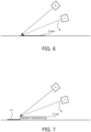
- the determination unit 312 determines whether or not the identity certificate 5 appearing in the certificate image 21 is authentic (step S13). Specifically, as described above, the probability is relatively high that the thickness of an identity certificate 5_fake is thinner (particularly, much thinner) than the thickness of an identity certificate 5_real. Accordingly, as illustrated in FIG. 6 that is a side view illustrating the identity certificate 5_fake illuminated by the light source 1, it is highly probable that a shadow 51 of the identity certificate 5_fake is hardly created when the light source 1 illuminates the identity certificate 5 _fake with the illumination light IL.
- FIG. 7 that is a side view illustrating the identity certificate 5_real illuminated by the light source 1
- a shadow 51 of the identity certificate 5_fake is created when the light source 1 illuminates the identity certificate 5_real with the illumination light IL.
- the identity certificate 5_real has a certain thickness.
- it is highly probable that the shadow 51 of the identity certificate 5_real appears in the certificate image 21 in which the identity certificate 5_real appears.
- the determination unit 312 may determine that the identity certificate 5 appearing in the certificate image 21 is fake when the shadow 51 does not appear in the certificate image 21. In other words, the determination unit 312 may determine that the identity certificate 5_fake appears in the certificate image 21. In contrast, based on the shadow information, the determination unit 312 may determine that the identity certificate 5 appearing in the certificate image 21 is authentic when the shadow 51 appears in the certificate image 21. In other words, the determination unit 312 may determine that the identity certificate 5_real appears in the certificate image 21.
- the certificate determination system SYSa (particularly, the determination server 3) according to the first example embodiment can determine whether or not an identity certificate 5 appearing in a certificate image 21 is authentic, based on presence or absence of a shadow 51 of the identity certificate 5 appearing in the certificate image 21. Accordingly, the certificate determination system SYSa (particularly, the determination server 3) can determine whether or not the identity certificate 5 appearing in the certificate image 21 is authentic, at relatively low costs, compared to a case where a human determines, by visually checking the certificate image 21, whether or not the identity certificate 5 appearing in the certificate image 21 is authentic.
- certificate determination system SYS a certificate determination system SYS according to a second example embodiment is described.
- the certificate determination system SYS according to the second example embodiment is referred to as "certificate determination system SYSb".
- the certificate determination system SYSb according to the second example embodiment is different, compared to the certificate determination system SYSa according to the first example embodiment, in that the certificate determination system SYSb includes a determination server 3b in place of the determination server 3.
- Other characteristics of the certificate determination system SYSb may be the same as the other characteristics of the certificate determination system SYSa.
- the determination server 3b similarly to the determination server 3, generates shadow information related to a shadow 51 of an identity certificate 5 appearing in a certificate image 21, and performs certificate determination operation for determining, based on the generated shadow information, whether or not the identity certificate 5 appearing in the certificate image 21 is authentic. However, the determination server 3b generates the shadow information including information related a length L of the shadow 51 of the identity certificate 5. In such a respect, the determination server 3b is different from the determination server 3 that generates shadow information including information related to presence or absence of the shadow 51 of the identity certificate 5. Other characteristics of the determination server 3b may be the same as the other characteristics of the determination server 3.
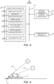
- FIG. 8 is a block diagram illustrating a configuration of the determination server 3b in the second example embodiment.
- the determination server 3b is different, compared to the determination server 3, in that an image analysis unit 311b, in place of the image analysis unit 311, is implemented in the computation apparatus 31. Further, the determination server 3b is different, compared to the determination server 3, in that the storage apparatus 32 stores a shadow length DB 321b, which is one specific example of "estimated length data". Other components of the determination server 3b may be the same as the other components of the determination server 3.
- the image analysis unit 311b is different, compared to the image analysis unit 311, in that the image analysis unit 311b includes a certificate identification unit 314b, a camera angle calculation unit 315b, which is one specific example of "calculation unit”, a light source angle calculation unit 316b, which is one specific example of “calculation unit”, and a shadow length calculation unit 317b, which is one specific example of "generation unit”, in place of the shadow detection unit 313.
- the certificate identification unit 314b, the camera angle calculation unit 315b, the light source angle calculation unit 316b, and the shadow length calculation unit 317b will be described in detail later with reference to FIG. 10 and others, an outline of the operations is described below.
- the certificate identification unit 314b identifies, based on a certificate image 21, a type of an identity certificate 5 appearing in the certificate image 21.
- the camera angle calculation unit 315b calculates, based on the certificate image 21, an angle of the camera 2 (hereinafter, referred to as "camera angle ⁇ c") to the identity certificate 5.
- the light source angle calculation unit 316b calculates, based on the certificate image 21, an angle of the light source 1 (hereinafter, referred to as "light source angle ⁇ o”) to the identity certificate 5.
- the shadow length calculation unit 317b calculates, based on the certificate image 21, a length L of a shadow 51 of the identity certificate 5 appearing in the certificate image 21.
- the determination unit 312 determines, based on the camera angle ⁇ c calculated by the camera angle calculation unit 315b, the light source angle ⁇ o calculated by the light source angle calculation unit 316b, and the length L of the shadow 51 calculated by the shadow length calculation unit 317b, whether or not the identity certificate 5 appearing in the certificate image 21 is authentic.
- the camera angle ⁇ c is a parameter (in other words, an indicator) indicating a relative positional relationship between the camera 2 and the identity certificate 5.
- An example of the camera angle ⁇ c is illustrated in FIG. 9 .
- the camera angle ⁇ c may indicate an angle that a camera axis AC extending from the camera 2 forms with a surface of the identity certificate 5.
- the camera angle ⁇ c may indicate at least one of an angle that the camera axis AC forms with an axis along the surface of the identity certificate 5 (for example, an axis along any one of a short side and a long side of the identity certificate 5) in a vertical direction (see FIG.
- the camera axis AC may be an axis extending from the camera 2 toward a predetermined position on the identity certificate 5 (in the example illustrated in FIG. 9 , an upper end of the identity certificate 5).
- the camera axis AC may be an axis along an optical axis of an optical system (for example, a lens) included in the camera 2.
- the light source angle ⁇ o is a parameter (in other words, an indicator) indicating a relative positional relationship between the light source 1 and the identity certificate 5.
- An example of the light source angle ⁇ o is illustrated in FIG. 9 .
- the light source angle ⁇ o may indicate an angle that a light source axis OC extending from the light source 1 forms with the surface of the identity certificate 5.
- the light source angle ⁇ o may indicate at least one of an angle that the light source axis OC forms with an axis along the surface of the identity certificate 5 (for example, an axis along any one of the short side and the long side of the identity certificate 5) in the vertical direction (see FIG.
- the light source axis OC may be an axis extending from the light source 1 toward a predetermined position on the identity certificate 5 (in the example illustrated in FIG. 9 , the upper end of the identity certificate 5).
- the light source axis OC may be an axis along an optical axis of an optical system (for example, a lens) included in the light source 1.
- the light source axis OC may be an axis along a direction in which the illumination light IL emitted from the light source 1 travels.
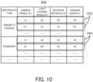
- the shadow length DB 321b is a database that is referred to by the determination unit 312 in order to determine whether or not the identity certificate 5 appearing in the certificate image 21 is authentic. Specifically, the shadow length DB 321b is used to estimate a length L of a shadow 51 of the identity certificate 5 presumed to appear in the certificate image 21, based on the camera angle ⁇ c calculated by the camera angle calculation unit 315b and the light source angle ⁇ o calculated by the light source angle calculation unit 316b. Accordingly, the shadow length DB 321b is a database indicating a relationship between the camera angle ⁇ c and the light source angle ⁇ o, and the length L of the shadow 51. An example of a data structure of the shadow length DB 321b is illustrated in FIG. 10 .
- the shadow length DB 321b includes a plurality of data records 322b.
- the length L of the shadow 51 of the identity certificate 5_real is associated with the camera angle ⁇ c and the light source angle ⁇ .
- the shadow 51 here is a shadow presumed to appear in a certificate image 21 when it is assumed that the camera 2 captures an image of the real identity certificate 5_real illuminated by the light source 1 in a situation where the camera angle ⁇ c is a predetermined first angle and the light source angle ⁇ o is a predetermined second angle.
- each data record 322b associated with the camera angle ⁇ c and the light source angle ⁇ o is the logical length L (in other words, the length L in design) of the shadow 51 of the identity certificate 5_real presumed to appear in the certificate image 21 when it is assumed that the camera 2 disposed in such a manner that the camera angle ⁇ c is the predetermined second angle captures an image of the identity certificate 5_real illuminated by the light source 1 disposed in such a manner that the light source angle ⁇ o is the predetermined second angle.
- L the length L in design
- the shadow length DB 321b includes, for example, (i) a data record 322b indicating that when it is assumed that the camera 2 disposed in such a manner that the camera angle ⁇ c is an angle a1 captures an image of the identity certificate 5_real illuminated by the light source 1 disposed in such a manner that the light source angle ⁇ o is an angle a2, the length L of the shadow 51 of the identity certificate 5_real presumed to then appear in the certificate image 21 is a4, and (ii) a data record 322b indicating that when it is assumed that the camera 2 disposed in such a manner that the camera angle ⁇ c is an angle b 1 captures an image of the identity certificate 5_real illuminated by the light source 1 disposed in such a manner that the light source angle ⁇ o is an angle b2, the length L of the shadow 51 of the identity certificate 5_real presumed to then appear in the certificate image 21 is b4.
- the length L of the shadow 51 of the identity certificate 5_real may change also depending on a distance (that is, an interval) D between the light source 1 and the camera 2, in addition to the light source angle ⁇ o and the camera angle ⁇ c. Accordingly, in each data record 322b, the length L of the shadow 51 of the identity certificate 5_real may be associated with the camera angle ⁇ c, the light source angle ⁇ o, and the distance D between the light source 1 and the camera 2.
- the shadow 51 here is a shadow presumed to appear in a certificate image 21 when it is assumed that the camera 2 captures an image of the real identity certificate 5_real illuminated by the light source 1 in a situation where the camera angle ⁇ c is the predetermined first angle, the light source angle ⁇ o is the predetermined second angle, and the distance D between the light source 1 and the camera 2 is a predetermined distance.
- the "distance" in the second example embodiment may include at least one of a distance along an X axis, a distance along a Y axis, and a distance along a Z axis in an XYZ coordinate system with the X, Y, and Z axes being mutually orthogonal. In the example illustrated in FIG.
- the shadow length DB 321b includes, for example, (i) the data record 322b indicating that when it is assumed that the camera 2 disposed in such a manner that the camera angle ⁇ c is the angle a1 and the camera 2 is a distance a3 away from the light source 1 captures an image of the identity certificate 5_real illuminated by the light source 1 disposed in such a manner that the light source angle ⁇ o is the angle a2, the length L of the shadow 51 of the identity certificate 5_real presumed to then appear in the certificate image 21 is a4, and (ii) the data record 322b indicating that when it is assumed that the camera 2 disposed in such a manner that the camera angle ⁇ c is the angle b1 and the camera 2 is a distance b3 away from the light source 1 captures an image of the identity certificate 5_real illuminated by the light source 1 disposed in such a manner that the light source angle ⁇ o is the angle b2, the length L of the shadow 51 of the identity certificate 5_real presumed to
- the length L of the shadow 51 of the identity certificate 5_real may change also depending on the thickness of the identity certificate 5_real, in addition to the light source angle ⁇ o and the camera angle ⁇ c.
- the thickness of the identity certificate 5_real depends on a type of the identity certificate 5_real.
- the thickness of a driver's license which is an example of the identity certificate 5_real
- the shadow length DB 321b may include a data record 322b, for each type of identity certificate 5_real.
- the shadow length DB 321b may include a data record 322b indicating the length of the shadow 51 of the identity certificate 5_real of a first type, and a data record 322b indicating the length of the shadow 51 of the identity certificate 5_real of a second type that is different from the first type.
- the shadow length DB 321b includes data records 322b each indicating the length L of the shadow 51 of a driver's license, which is an example of the identity certificate 5_real, and data records 322b each indicating the length L of the shadow 51 of a passport, which is an example of the identity certificate 5_real.
- the determination unit 312 estimates a length L of a shadow 51 of the identity certificate 5 (that is, an estimated value of the length L of the shadow 51) presumed to appear in the certificate image 21. In other words, the determination unit 312 estimates the length L of the shadow 51 (that is, an estimated value of the length L of the shadow 51) appearing in the certificate image 21 when it is assumed that the real identity certificate 5_real appears in the certificate image 21.
- the determination unit 312 determines whether or not the identity certificate 5 appearing in the certificate image 21 is authentic.
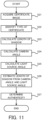
- FIG. 11 is a flowchart illustrating a flow of the certificate determination operation performed by the determination server 3 in the second example embodiment.
- the image analysis unit 31 by using the communication apparatus 33, acquires a certificate image 21 transmitted from the camera 2 through the communication network 4 (step S21).
- the certificate identification unit 314b in the image analysis unit 311 identifies a type of an identity certificate 5 appearing in the certificate image 21 (step S22).
- the certificate identification unit 314b by analyzing the certificate image 21, identifies the type of the identity certificate 5 appearing in the certificate image 21 (step S22).
- the certificate identification unit 314b may identify the type of the identity certificate 5, based on a characteristic (for example, at least one of size, color, and shape) of the identity certificate 5 appearing in the certificate image 21.
- the certificate identification unit 314b may identify the type of the identity certificate 5 by performing, on the certificate image 21, a pattern matching process using a template in conformity with a format of the identity certificate 5.
- the certificate identification unit 314b similarly to the shadow detection unit 313 in the first example embodiment, may identify an image region (that is, a certificate region 22) where the identity certificate 5 appears in the certificate image 21. Note that when the type of the identity certificate 5 appearing in the certificate image 21 is already known to the determination server 3, the image analysis unit 311 does not need to identify the type of the identity certificate 5. In such a case, the image analysis unit 311 does not need to include the certificate identification unit 314b.
- the shadow length calculation unit 317b calculates a length L of a shadow 51 of the identity certificate 5 appearing in the certificate image 21 (step S23).
- the size of the identity certificate 5 is a unique value depending on the type of the identity certificate 5. Accordingly, the size of the identity certificate 5 can be used for a reference length when the length L of the shadow 51 is calculated. Accordingly, first, the shadow length calculation unit 317b identifies a size (for example, a length of at least one of a long side and a short side) of the identity certificate 5, based on the type of the identity certificate 5 identified by the certificate identification unit 314b.
- the size of the identity certificate 5 is equivalent to the size of the certificate region 22 in the certificate image 21.
- the shadow length calculation unit 317b similarly to the shadow detection unit 313 described in the first example embodiment, detects an image region (that is, a shadow region 23) where a shadow extending outward from the certificate region 22 appears. Thereafter, the shadow length calculation unit 317b calculates a size of the detected shadow region 23, based on the size of the certificate region 22.
- the size of the shadow region 23 may be, for example, a distance from one end portion of the shadow region 23 adjacent to the certificate region 22 to the other end portion of the shadow region 23 far from the certificate region 22, along a direction in which the illumination light IL travels.
- the calculated size of the shadow region 23 is used for the length L of the shadow 51.
- a result of the calculation of the length L of the shadow 51 by the shadow length calculation unit 317b in step S23 is outputted, as shadow information, from the shadow length calculation unit 317b to the determination unit 312.
- the shadow information including information related to the length L of the shadow 51 in the certificate image 21 is outputted from the shadow length calculation unit 317b to the determination unit 312.
- the camera angle calculation unit 315b calculates an angle of the camera 2 (that is, a camera angle ⁇ c) to the identity certificate 5 (step S24). Specifically, when the camera angle ⁇ c is changed, a change occurs in the ratio between the lengths of two intersecting sides (for example, the long side and the short side) of the identity certificate 5 appearing in the certificate image 21.
- FIG. 12 illustrates a certificate image 21 generated in a situation where the camera angle ⁇ c between the camera axis AC and the surface of the identity certificate 5 is relatively large
- the camera angle calculation unit 315b may calculate the camera angle ⁇ c, based on the ratio between the lengths of the two intersecting sides of the identity certificate 5.
- the camera angle ⁇ c calculated here corresponds to a camera angle ⁇ c at a time when the camera 2 captures the image of the identity certificate 5.
- the camera angle ⁇ c calculated in step S24 is outputted from the camera angle calculation unit 315b to the determination unit 312.
- the light source angle calculation unit 316b calculates an angle of the light source 1 (that is, a light source angle ⁇ o) to the identity certificate 5 (step S25). Specifically, in a case where the positional relationship between the light source 1 and the camera 2 is fixed as described above, when the camera angle ⁇ c is determined, the light source angle ⁇ o is also uniquely determined. Alternatively, in a case where the positional relationship between the light source 1 and the camera 2 is information known to the determination server 3 even if the positional relationship between the light source 1 and the camera 2 is not fixed, when the camera angle ⁇ c is determined, the light source angle ⁇ o is also uniquely determined.
- the light source angle calculation unit 316b can calculate the light source angle ⁇ o, based on the camera angle ⁇ c (further, based also on the positional relationship between the light source 1 and the camera 2 as necessary).
- the light source angle ⁇ o calculated here corresponds to a light source angle ⁇ o at the time when the camera 2 captures the image of the identity certificate 5.
- the light source angle ⁇ o calculated in step S25 is outputted from the light source angle calculation unit 316b to the determination unit 312.
- the determination unit 312 estimates a length L of a shadow 51 of the identity certificate 5 presumed to appear in the certificate image 21 (step S26). In other words, the determination unit 312 estimates the length L of the shadow 51 (that is, an estimated value of the length L of the shadow 51) appearing in the certificate image 21 when it is assumed that the real identity certificate 5_real appears in the certificate image 21.
- the determination unit 312 estimates the logical length L (in other words, the length L in design) of the shadow 51 of the identity certificate 5_real presumed to appear in the certificate image 21 when it is assumed that the camera 2 disposed at a position based on the camera angle ⁇ c calculated in step S24 captures an image of the real identity certificate 5_real illuminated by the light source 1 disposed at a position based on the light source angle ⁇ o calculated in step S25.
- the determination unit 312 extracts, from the shadow length DB 321b, a data record 322b corresponding to the camera angle ⁇ c calculated in step S24 and the light source angle ⁇ o calculated in step S25. Thereafter, the determination unit 312 uses a length L of the shadow 51 indicated in the extracted data record 322b for the estimated value of the length L of the shadow 51.
- the determination unit 312 may identify a distance D between the light source 1 and the camera 2, and may extract, from the shadow length DB 321b, a data record 322b corresponding to the identified distance D.
- the distance D between the light source 1 and the camera 2 is a fixed value when the positional relationship between the light source 1 and the camera 2 is fixed.
- the distance D between the light source 1 and the camera 2 is a variable value.
- the determination server 3 can identify the distance D between the light source 1 and the camera 2.
- the determination unit 312 determines whether or not the identity certificate 5 appearing in the certificate image 21 is authentic (step S27). Specifically, as illustrated in FIG. 14 , when the identity certificate 5 appearing in the certificate image 21 is authentic (that is, the identity certificate 5_real), the calculated value L1 of the length L of the shadow 51 is approximately the same value as the estimated value of the length L of the shadow 51 (that is, the logical length L). In contrast, as illustrated FIG.
- the calculated value L2 of the length L of the shadow 51 is a different value from the estimated value of the length L (that is, the logical length L) of the shadow 51.
- the calculated value of the length L of the shadow 51 indicates the length L of the shadow 51 of the identity certificate 5_fake that has a different thickness from the thickness of the identity certificate 5_real.
- the calculated value L2 of the length L of the shadow 51 of the identity certificate 5_fake is a different value from the length L1 of the shadow 51 of the identity certificate 5_real (alternatively, the estimated value of the length L of the shadow 51 corresponding to the logical value of the length L1 of the shadow 51 of the identity certificate 5_real). Accordingly, the determination unit 312 can determine whether or not the identity certificate 5 appearing in the certificate image 21 is authentic, by comparing the calculated value of the length L of the shadow 51 calculated in step S23 and the estimated value of the length L of the shadow 51 estimated in step S26.
- the determination unit 312 may determine that the identity certificate 5 appearing in the certificate image 21 is not authentic.
- the determination unit 312 may determine that the identity certificate 5 appearing in the certificate image 21 is authentic.
- first and second allowances may be set to appropriate values that make it possible to distinguish, based on the length L of the shadow 51 of the identity certificate 5 appearing in the certificate image 21, between a state where the identity certificate 5 appearing in the certificate image 21 is authentic and a state where the identity certificate 5 appearing in the certificate image 21 is not authentic.
- Such first and second allowances may be set by experiment or simulation.
- the first allowance may be the same as, or may be different from, the second allowance.
- the certificate determination system SYSb (particularly, the determination server 3b) according to the second example embodiment can determine whether or not an identity certificate 5 appearing in a certificate image 21 is authentic, based on the length L of a shadow 51 of the identity certificate 5 appearing in the certificate image 21. Accordingly, the certificate determination system SYSb (particularly, the determination server 3b) can determine whether or not the identity certificate 5 appearing in the certificate image 21 is authentic, at relatively low costs, compared to a case where a human determines, by visually checking the certificate image 21, whether or not the identity certificate 5 appearing in the certificate image 21 is authentic.
- the determination server 3b determines that the identity certificate 5 appearing in the certificate image 21 is not authentic when the length L of the shadow 51 appearing in the certificate image 21 is different from the length L of a shadow 51 of the real identity certificate 5_real. Accordingly, the certificate determination system SYSb (particularly, the determination server 3b) can determine whether or not the identity certificate 5 appearing in the certificate image 21 is authentic, with higher accuracy.
- the determination server 3b may generate shadow information including information related to a change (typically, time-series changes) in the length L of a shadow 51 of the identity certificate 5. Specifically, the determination server 3b acquires a plurality of certificate images 21 transmitted from the camera 2. The plurality of certificate images 21 are generated by repeating an operation, by the camera 2, of capturing an image of the identity certificate 5, and an operation of changing a positional relationship between the identity certificate 5 and at least one of the light source 1 and the camera 2. In other words, in the first modified example, each time the positional relationship between the identity certificate 5 and at least one of the light source 1 and the camera 2 is changed, the camera 2 captures an image of the identity certificate 5.
- a change typically, time-series changes
- the plurality of certificate images 21 may be a plurality of images included in a video.
- the shadow length calculation unit 317b in the determination server 3b calculates a length L of a shadow 51 of the identity certificate 5 appearing in each of the plurality of certificate images 21.
- the shadow length calculation unit 317b can calculate time-series changes in the length L of the shadow 51. Results of the calculation of the length L of the shadow 51 by the shadow length calculation unit 317b are outputted, as shadow information, from the shadow length calculation unit 317b to the determination unit 312.
- the camera angle calculation unit 315b calculates a camera angle ⁇ c, based on each of the plurality of certificate images 21. As a result, the camera angle calculation unit 315b calculates time-series changes in the camera angle ⁇ c. Similarly, the light source angle calculation unit 316b calculates time-series changes in the light source angle ⁇ o, based on the time-series changes in the camera angle ⁇ c.
- the determination unit 312 estimates time-series changes in the length L of a shadow 51 of the identity certificate 5 presumed to appear in the certificate images 21. In other words, the determination unit 312 estimates time-series changes in the length L of the shadow 51 (that is, estimated values of time-series changes in the length L of the shadow 51) appearing in the certificate images 21 when it is assumed that the real identity certificate 5_real appears in the certificate images 21.
- the determination unit 312 determines whether or not the identity certificate 5 appearing in the certificate images 21 is authentic, by comparing the calculated values of the time-series changes in the length L of the shadow 51 calculated by the shadow length calculation unit 317b and the estimated values of the time-series changes in the length L of the shadow 51 estimated by the determination unit 312.
- the determination unit 312 determines whether or not the identity certificate 5 appearing in the certificate images 21 is authentic, by comparing a pattern of changes in the length L of the shadow 51 actually appearing in the certificate images 21 (hereinafter, referred to as "actual change pattern") and a pattern of changes in the length L of the shadow 51 presumed to appear in the certificate images 21 (hereinafter, referred to as "presumed change pattern"). For example, when a degree of similarity between the actual change pattern of the length L of the shadow 51 and the presumed change pattern of the length L of the shadow 51 is higher than a first threshold value, the determination unit 312 may determine that the identity certificate 5 appearing in the certificate images 21 is authentic.
- actual change pattern a pattern of changes in the length L of the shadow 51 actually appearing in the certificate images 21
- predetermined change pattern a pattern of changes in the length L of the shadow 51 presumed to appear in the certificate images 21
- the determination unit 312 may determine that the identity certificate 5 appearing in the certificate images 21 is not authentic.
- first and second threshold values may be set to appropriate values that make it possible to distinguish, based on a pattern of changes (that is, time-series changes) in the length L of the shadow 51 of the identity certificate 5 appearing in the certificate images 21, between a state where the identity certificate 5 appearing in the certificate images 21 is authentic and a state where the identity certificate 5 appearing in the certificate images 21 is not authentic.
- Such first and second threshold values may be set by experiment or simulation.
- the first threshold value may be the same as, or may be different from, the second threshold value.
- the determination server 3b performs the certificate determination operation by using time-series changes in the length L of the shadow 51.
- the determination server 3b may perform the certificate determination operation by using arbitrary time-series changes in the shadow 51.
- the determination server 3b may perform the certificate determination operation by using time-series changes in an arbitrary parameter indicating a state of the shadow 51. For example, when the positional relationship between the identity certificate 5 and at least one of the light source 1 and the camera 2 is changed, a change may occur in a direction in which the shadow 51 extends from the identity certificate 5 (that is, the direction of the shadow 51). For example, FIG.
- the determination server 3b may perform the certificate determination operation by using time-series changes in the direction in which the shadow 51 extends.
- the shadow length calculation unit 317b in the determination server 3b may calculate a direction in which the shadow 51 of the identity certificate 5 appearing in each of the plurality of certificate images 21 extends.
- the shadow length calculation unit 317b can calculate time-series changes in the direction in which the shadow 51 extends.
- the determination unit 312 estimates time-series changes in the direction in which a shadow 51 of the identity certificate 5 presumed to appear in the certificate images 21 extends, based on the time-series changes in the camera angle ⁇ c, the time-series changes in the light source angle ⁇ o, and the shadow length DB 321b.
- the direction in which the shadow 51 of the identity certificate 5_real presumed to appear in the certificate image 21 extends be associated with the camera angle ⁇ c and the light source angle ⁇ o in each data record 322b in the shadow length DB 321b, as illustrated in FIG.
- the determination unit 312 may determine whether or not the identity certificate 5 appearing in the certificate images 21 is authentic, by comparing calculated values of the time-series changes in the direction in which the shadow 51 extends, calculated by the shadow length calculation unit 317b, and estimated values of the time-series changes in the direction in which the shadow 51 extends, estimated by the determination unit 312. For example, when a degree of similarity between an actual change pattern of the direction in which the shadow 51 extends and a presumed change pattern of the direction in which the shadow 51 extends is higher than a third threshold value, the determination unit 312 may determine that the identity certificate 5 appearing in the certificate images 21 is authentic.
- the determination unit 312 may determine that the identity certificate 5 appearing in the certificate images 21 is not authentic.
- the third and fourth threshold values may be set to appropriate values that make it possible to distinguish, based on a pattern of changes in the direction in which the shadow 51 of the identity certificate 5 appearing in the certificate images 21 extends, between a state where the identity certificate 5 appearing in the certificate images 21 is authentic and a state where the identity certificate 5 appearing in the certificate images 21 is not authentic.
- Such third and fourth threshold values may be set by experiment or simulation.
- the third threshold value may be the same as, or may be different from, the fourth threshold value.
- step S26 in FIG. 11 the determination unit 312 estimates the length L of the shadow 51 of the identity certificate 5, based on the camera angle ⁇ c, the light source angle ⁇ o, and the shadow length DB 321b. Thereafter, in step S27 in FIG. 11 , the determination unit 312 determines whether or not the identity certificate 5 appearing in the certificate image 21 is authentic, by comparing a calculated value of the length L of the shadow 51 calculated by the shadow length calculation unit 317b in step S23 and an estimated value of the length L of the shadow 51 estimated by the determination unit 312 in step S26.
- the determination unit 312 may estimates, based on the length L of the shadow 51 calculated by the shadow length calculation unit 317b in step S23 and the shadow length DB 321b, a light source angle ⁇ o that the light source 1 is presumed to form with the identity certificate 5_real when it is assumed that the shadow 51 having the length L calculated by the shadow length calculation unit 317b appears in the certificate image 21. In other words, the determination unit 312 may estimate an estimated value of the light source angle ⁇ .
- the determination unit 312 may determine whether or not the identity certificate 5 appearing in the certificate image 21 is authentic, based on the actual calculated value of the light source angle ⁇ o calculated in step S25, and the estimated value of the light source angle ⁇ o estimated in step S26.
- the estimated value of the light source angle ⁇ o estimated in step S26 is approximately the same value as the actual calculated value of the light source angle ⁇ .
- the estimated value of the light source angle ⁇ o estimated in step S26 is a different value from the actual calculated value of the light source angle ⁇ .
- the determination unit 312 can determine whether or not the identity certificate 5 appearing in the certificate image 21 is authentic, by comparing the calculated value of the light source angle ⁇ o calculated in step S24 and the estimated value of the light source angle ⁇ o estimated in step S26.
- the determination unit 312 can determine whether or not the identity certificate 5 appearing in the certificate image 21 is authentic, by determining whether or not the actual light source angle ⁇ o calculated in step S24 seems to be authentic, on the basis of an ideal light source angle ⁇ o (in other words, a light source angle ⁇ o in design) at which a shadow 51 having the length L calculated in step S23 is created. For example, when a difference between the calculated value of the light source angle ⁇ o and the estimated value of the light source angle ⁇ o is more than a predetermined third allowance (that is, the calculated value of the light source angle ⁇ o is greatly different from the estimated value of the light source angle ⁇ o), the determination unit 312 may determine that the identity certificate 5 appearing in the certificate image 21 is not authentic.
- a predetermined third allowance that is, the calculated value of the light source angle ⁇ o is greatly different from the estimated value of the light source angle ⁇ o
- the determination unit 312 may determine that the identity certificate 5 appearing in the certificate image 21 is authentic.
- the third and the fourth allowances may be set to appropriate values that make it possible to distinguish, based on the light source angle ⁇ o, between a state where the identity certificate 5 appearing in the certificate image 21 is authentic and a state where the identity certificate 5 appearing in the certificate image 21 is not authentic.
- Such third and fourth allowances may be set by experiment or simulation.
- the third allowance may be the same as, or may be different from, the fourth allowance.
- the camera angle calculation unit 315b does not need to calculate a camera angle ⁇ c.
- the image analysis unit 311 does not need to include the camera angle calculation unit 315b.
- the determination server 3b performs the certificate determination operation by using the camera angle ⁇ c.
- the camera angle ⁇ c is one specific example of a parameter indicating the relative positional relationship between the camera 2 and the identity certificate 5.
- the determination server 3b may perform the certificate determination operation by using an arbitrary parameter indicating the relative positional relationship between the camera 2 and the identity certificate 5, in addition to, or in place of, the camera angle ⁇ c.
- the arbitrary parameter indicating the relative positional relationship between the camera 2 and the identity certificate 5 include at least one of a distance from the identity certificate 5 to the camera 2, and an azimuth direction in which the camera 2 is positioned relative to the identity certificate 5.
- the determination server 3b performs the certificate determination operation by using the light source angle ⁇ .
- the light source angle ⁇ o is one specific example of a parameter indicating the relative positional relationship between the light source 1 and the identity certificate 5.
- the determination server 3b may perform the certificate determination operation by using an arbitrary parameter indicating the relative positional relationship between the light source 1 and the identity certificate 5, in addition to, or in place of, the light source angle ⁇ .
- the arbitrary parameter indicating the relative positional relationship between the light source 1 and the identity certificate 5 include at least one of a distance from the identity certificate 5 to the light source 1, and an azimuth direction in which the light source 1 is positioned relative to the identity certificate 5.
- certificate determination system SYSc is different, compared to the certificate determination system SYSa according to the first example embodiment, in that the certificate determination system SYSc includes a determination server 3c in place of the determination server 3.
- Other characteristics of the certificate determination system SYSc may be the same as the other characteristics of the certificate determination system SYSa. Accordingly, in the following, a description is given of the determination server 3c in the third example embodiment, focused mainly on differences between the determination server 3c and the determination server 3, with reference to FIG. 18.
- FIG. 18 is a block diagram illustrating a configuration of the determination server 3c in the third example embodiment.
- the determination server 3c is different, compared to the determination server 3, in that a light source control unit 318c, which is one specific example of "control unit”, is implemented as a logical processing block in the computation apparatus 31.
- Other components of the determination server 3c may be the same as the other components of the determination server 3.
- the light source control unit 318c is capable of controlling the light source 1 through the communication network 4.
- the light source control unit 318c may control a characteristic (for example, intensity) of the illumination light IL, by controlling the light source 1.
- the light source control unit 318c may control the characteristic of the illumination light II, in such a manner that a shadow 51 appropriately appears in a certificate image 21, compared to the shadow 51 before the characteristic of the illumination light II, is controlled.
- a state where "a shadow 51 appropriately appears in a certificate image 21" may refer to, for example, a state where a shadow 51 appears in a certificate image 21 to such an extent that the image analysis unit 311 can appropriately detect the shadow 51.
- the state where "a shadow 51 appropriately appears in a certificate image 21" may refer to a state where a shadow 51 clearly appears in a certificate image 21 to such an extent that a contrast between a shadow region 23 where the shadow 51 appears and an image region other than the shadow region 23 is equal to or more than a certain amount.
- Such a certificate determination system SYSc according to the third example embodiment can appropriately detect the shadow 51 appearing in the certificate image 21, while achieving advantageous effects similar to the above-described advantageous effects that can be achieved by the certificate determination system SYSa according to the first example embodiment.
- the light source control unit 318c may control the camera 2 through the communication network 4, in addition to, or in place of, controlling the light source 1.
- the light source control unit 318c may control an optical characteristic (for example, sensitivity) of the camera 2, by controlling the camera 2.
- the light source control unit 318c may control the optical characteristic of the camera 2 in such a manner that a shadow 51 appropriately appears in a certificate image 21, compared to the shadow 51 before the optical characteristic of the camera 2 is controlled.
- the certificate determination system SYSc can also appropriately detect the shadow 51 appearing in the certificate image 21, while achieving advantageous effects similar to the above-described advantageous effects that can be achieved by the certificate determination system SYSa according to the first example embodiment.
Landscapes
- Engineering & Computer Science (AREA)
- Physics & Mathematics (AREA)
- General Physics & Mathematics (AREA)
- Theoretical Computer Science (AREA)
- Computer Vision & Pattern Recognition (AREA)
- Multimedia (AREA)
- Health & Medical Sciences (AREA)
- General Health & Medical Sciences (AREA)
- Toxicology (AREA)
- Quality & Reliability (AREA)
- Software Systems (AREA)
- Collating Specific Patterns (AREA)
- Image Analysis (AREA)
Abstract
Description
- The present disclosure relates to a technical field of a certificate determination apparatus, a certificate determination method, and a recording medium that are able to determine whether or not an identity certificate appearing in an image is authentic.
- In various fields, a method is adopted in which the identity of a user is proved by using an image acquired by capturing an image of an identity certificate of the user. As an example, when a contract for a mobile phone subscription is made online, a method is adopted in which a subscriber is requested to transmit an image of an identity certificate of the subscriber, and the identity of the subscriber is proved by using the identity certificate appearing in the transmitted image.
- To appropriately prove the identity of a user, it is desired to appropriately determine whether or not an identity certificate appearing in an image is authentic. In other words, it is desired to appropriately determine whether an image used to prove the identity of a user is an image generated by capturing an image of a real identity certificate, or an image generated by capturing an image of a fake identity certificate (for example, a document created by copying the identity certificate). In the current situation, however, a human determines, by visually checking an image, whether or not an identity certificate appearing in the image is authentic. Accordingly, a technical problem arises that costs are relatively high for determining whether or not an identity certificate appearing in an image is authentic.
- An example object of the present disclosure is to provide a certificate determination apparatus, a certificate determination method, and a recording medium by which the above-described technical problem can be solved. As an example, an example object of the present disclosure is to provide a certificate determination apparatus, a certificate determination method, and a recording medium that are able to determine whether or not an identity certificate appearing in an image is authentic, at relatively low costs.
- One example aspect of a certificate determination apparatus in the present disclosure includes: a generation unit configured to generate, based on an image in which an identity certificate appears, shadow information related a shadow of the identity certificate appearing in the image; and a determination unit configured to determine, based on the shadow information, whether or not the identity certificate appearing in the image is authentic.
- One example aspect of a certificate determination method in the present disclosure includes: One example aspect of a certificate determination apparatus in the present disclosure includes: a generation unit configured to generate, based on an image in which an identity certificate appears, shadow information related a shadow of the identity certificate appearing in the image; and a determination unit configured to determine, based on the shadow information, whether or not the identity certificate appearing in the image is authentic.
- One example aspect of a recording medium in the present disclosure is a recording medium storing a computer program that causes a computer to execute a certificate determination method, the certificate determination method includes: a generation step of generating, based on an image in which an identity certificate appears, shadow information related a shadow of the identity certificate appearing in the image; and a determination step of determining, based on the shadow information, whether or not the identity certificate appearing in the image is authentic.
-
- [
FIG. 1] FIG. 1 is a block diagram illustrating an entire configuration of a certificate determination system according to a first example embodiment. - [
FIG. 2] FIG. 2 is a side view illustrating an example of a light source and a camera capturing an image of an identity certificate. - [
FIG. 3] FIG. 3 is a plan view illustrating an example of a certificate image. - [
FIG. 4] FIG. 4 is a block diagram illustrating a configuration of a determination server in the first example embodiment. - [
FIG. 5] FIG. 5 is a flowchart illustrating a flow of certificate determination operation performed by the determination server in the first example embodiment. - [
FIG. 6] FIG. 6 is a side view illustrating a fake identity certificate illuminated by the light source. - [
FIG. 7] FIG. 7 is a side view illustrating a real identity certificate illuminated by the light source. - [
FIG. 8] FIG. 8 is a block diagram illustrating a configuration of a determination server in a second example embodiment. - [
FIG. 9] FIG. 9 is a side view illustrating a camera angle and a light source angle. - [
FIG. 10] FIG. 10 is a data structure diagram illustrating an example of a data structure of a shadow length DB. - [
FIG. 11] FIG. 11 is a flowchart illustrating a flow of certificate determination operation performed by the determination server in the second example embodiment. - [
FIG. 12] FIG. 12 is a plan view illustrating a certificate image generated in a situation where the camera angle is relatively large. - [
FIG. 13] FIG. 13 is a plan view illustrating a certificate image generated in a situation where the camera angle is relatively small. - [
FIG. 14] FIG. 14 is a side view illustrating the length of a shadow of a real identity certificate. - [
FIG. 15] FIG. 15 is a side view illustrating the length of a shadow of a fake identity certificate. - [
FIG. 16] FIG. 16 is plan views illustrating aspects of a changing direction in which a shadow extends. - [
FIG. 17] FIG. 17 is a data structure diagram illustrating an example of a data structure of a shadow length DB in a first modified example. - [
FIG. 18] FIG. 18 is a block diagram illustrating a configuration of a determination server in a third example embodiment. - Hereinafter, example embodiments of a certificate determination apparatus, a certificate determination method, and a recording medium are described with reference to the drawings. In the following, a description is given of certificate determination systems SYS to which the example embodiments of the certificate determination apparatus, the certificate determination method, and the recording medium are applied.
- First, a certificate determination system SYS according to a first example embodiment is described. In the following description, the certificate determination system SYS according to the first example embodiment is referred to as "certificate determination system SYSa".
- First, a configuration of the certificate determination system SYSa according to the first example embodiment is described with reference to
FIG. 1. FIG. 1 is a block diagram illustrating the configuration of the certificate determination system SYSa according to the first example embodiment. - As illustrated in
FIG. 1 , the certificate determination system SYSa includes alight source 1, acamera 2, which is one specific example of "imaging apparatus", and adetermination server 3, which is one specific example of "certificate determination apparatus". At least one of thelight source 1 and thecamera 2 is capable of communicating with thedetermination server 3 through a communication network (or an arbitrary control line) 4. Thecommunication network 4 may include a wired communication network, or may include a wireless communication network. - The
light source 1 and thecamera 2 are used to capture an image of anidentity certificate 5 of a user (seeFIG. 2 ). In the first example embodiment, theidentity certificate 5 may refer to a physical document that can be used to prove who the user is (in other words, identity or authenticity). Examples of theidentity certificate 5 include at least one of a driver's license, a passport (travel document), an insurance certificate, an individual number card, and an ID card. - An example of the
light source 1 and thecamera 2 capturing an image of theidentity certificate 5 is illustrated inFIG. 2 . As illustrated inFIG. 2 , thelight source 1 illuminates theidentity certificate 5 with illumination light IL. Thecamera 2 captures an image of theidentity certificate 5 illuminated with the illumination light II, from thelight source 1. As a result, thecamera 2 generates an image (hereinafter, referred to as "certificate image 21" as appropriate) in which theidentity certificate 5 appears. Thecamera 2 transmits the generatedcertificate image 21 to thedetermination server 3 through thecommunication network 4. - It is preferable that a positional relationship between the
light source 1 and thecamera 2 be fixed. In other words, it is preferable that the positional relationship between thelight source 1 and thecamera 2 not be changed. In such a case, it is preferable that the positional relationship between thelight source 1 and thecamera 2 be information known to thedetermination server 3. When the positional relationship between thelight source 1 and thecamera 2 is fixed, a single apparatus may include thelight source 1 and thecamera 2. In other words, a light source and a camera included in a single apparatus may be used for thelight source 1 and thecamera 2. As an example, a light source and a camera included in a smartphone or a tablet terminal may be used for thelight source 1 and thecamera 2. - However, the positional relationship between the
light source 1 and thecamera 2 does not need to be fixed. In other words, the positional relationship between thelight source 1 and thecamera 2 may be changed. In such a case, it is also preferable that the positional relationship between thelight source 1 and thecamera 2 be information known to thedetermination server 3. In other words, when the positional relationship between thelight source 1 and thecamera 2 is changed, it is preferable that thedetermination server 3 be able to identify the changed positional relationship between thelight source 1 and thecamera 2. - The
determination server 3 performs certificate determination operation for determining, based on thecertificate image 21, whether or not theidentity certificate 5 appearing in thecertificate image 21 is authentic. Specifically, based on thecertificate image 21, thedetermination server 3 determines whether thecertificate image 21 is an image generated by capturing an image of the real identity certificate 5 (hereinafter, referred to as "identity certificate 5_real" as appropriate), or is an image generated by capturing an image of a fake identity certificate 5 (hereinafter, referred to as "identity certificate 5_fake" as appropriate). Note that the real identity certificate 5_real in the first example embodiment may refer to theidentity certificate 5 itself (in other words, the original identity certificate 5). In contrast, the fake identity certificate 5_fake in the first example embodiment may refer to an imitatedidentity certificate 5 that is not theidentity certificate 5 itself. Examples of the identity certificate 5_fake include at least one of a document created by copying the identity certificate 5_real, and a display on which an image of the identity certificate 5_real appears. - In the first example embodiment, in particular, the
determination server 3 generates shadow information related to ashadow 51 of theidentity certificate 5 appearing thecertificate image 21 and, based on the generated shadow information, determines whether or not theidentity certificate 5 appearing in thecertificate image 21 is authentic. Specifically, when thelight source 1 illuminates the identity certificate 5_real with the illumination light IL as illustrated inFIG. 2 described above, ashadow 51 of the identity certificate 5_real is normally created. As a result, in thecertificate image 21 in which the identity certificate 5_real appears, theshadow 51 of the identity certificate 5_real also appears, as illustrated inFIG. 3 that is an example of thecertificate image 21. In contrast, the thickness of the identity certificate 5_fake, generally, differs from that of the identity certificate 5_real in many cases. For example, when a document created by copying the identity certificate 5_real as described above is used as the identity certificate 5_fake, the thickness of the identity certificate 5_fake is thinner than the thickness of the identity certificate 5_real. As a result, it is highly probable that a state of ashadow 51 of the identity certificate 5_fake created when thelight source 1 illuminates the identity certificate 5_fake with the illumination light IL is different from a state of theshadow 51 of the identity certificate 5_fake created when thelight source 1 illuminates the identity certificate 5_real with the illumination light IL. Accordingly, thedetermination server 3 can determine, based on the shadow information, whether or not theidentity certificate 5 appearing in thecertificate image 21 is authentic. - An example of a configuration of the
determination server 3 performing such certificate determination operation is illustrated inFIG. 4 . As illustrated inFIG. 4 , thedetermination server 3 includes acomputation apparatus 31, astorage apparatus 32, and acommunication apparatus 33. Thecomputation apparatus 31, thestorage apparatus 32, and thecommunication apparatus 33 are connected through a data bus 34. - The
computation apparatus 31 includes, for example, a CPU (Central Processing Unit). Thecomputation apparatus 31 reads a computer program. For example, thecomputation apparatus 31 may read the computer program stored in thestorage apparatus 32. For example, thecomputation apparatus 31 may read the computer program stored in a computer-readable nontransitory recording medium, by using an undepicted recording medium reading apparatus. Thecomputation apparatus 31 may acquire (that is, may download or may read) the computer program, via thecommunication apparatus 33, from an undepicted apparatus placed outside of thedetermination server 3. Thecomputation apparatus 31 executes the read computer program. As a result, in thecomputation apparatus 31, a logical functional block is implemented for performing an operation (for example, the above-described certificate determination operation) to be performed by thedetermination server 3. In other words, thecomputation apparatus 31 can function as a controller for implementing the logical functional block for performing the operation to be performed by thedetermination server 3. -
FIG. 4 illustrates examples of the logical functional block implemented in thecomputation apparatus 31 to perform the certificate determination operation. As illustrated inFIG. 4 , animage analysis unit 311 and adetermination unit 312, which is one specific example of "determination unit", are implemented in thecomputation apparatus 31. Further in theimage analysis unit 311, ashadow detection unit 313, which is one specific example of "generation unit", is implemented as a logical functional block. Operations of theimage analysis unit 311 and thedetermination unit 312 will be described in detail later with reference toFIG. 5 and others. - The
storage apparatus 32 can store desired data. For example, thestorage apparatus 32 may temporarily store the computer program that is executed by thecomputation apparatus 31. Thestorage apparatus 32 may temporarily store data that is temporarily used by thecomputation apparatus 31 when thecomputation apparatus 31 executes the computer program. Thestorage apparatus 32 may store data that thedetermination server 3 retains on a long-term basis. Note that thestorage apparatus 32 may include at least one of a RAM (Random Access Memory), a ROM (Read Only Memory), a hard disk apparatus, a magneto-optical disk apparatus, an SSD (Solid State Drive), and a disk array apparatus. - The
communication apparatus 33 is capable of communicating with at least one of thelight source 1 and thecamera 2 through thecommunication network 4. For example, thecommunication apparatus 33 may receive acertificate image 21 transmitted from thecamera 2 through thecommunication network 4. - Next, the certificate determination operation performed by the
determination server 3 in the first example embodiment is described with reference toFIG. 5. FIG. 5 is a flowchart illustrating a flow of the certificate determination operation performed by thedetermination server 3 in the first example embodiment. - As illustrated in
FIG. 5 , theimage analysis unit 311 acquires, by using thecommunication apparatus 33, acertificate image 21 transmitted from thecamera 2 through the communication network 4 (step S 11). - Thereafter, based on the
certificate image 21 acquired in step S11, theshadow detection unit 313 in theimage analysis unit 311 detects ashadow 51 of anidentity certificate 5 appearing in the certificate image 21 (step S12). Specifically, theshadow detection unit 313, by analyzing thecertificate image 21, identifies an image region (hereinafter, referred to as "certificate region 22", seeFIG. 3 ) where theidentity certificate 5 appears in thecertificate image 21. Thereafter, theshadow detection unit 313, by analyzing thecertificate image 21, determines whether or not there exists an image region (hereinafter, referred to as "shadow region 23", seeFIG. 3 ) that extends outward from thecertificate region 22 and in which theshadow 51 of theidentity certificate 5 appears. When theshadow region 23 exists, theshadow detection unit 313 determines that theshadow 51 of theidentity certificate 5 appears in thecertificate image 21. When theshadow region 23 does not exist, theshadow detection unit 313 determines that theshadow 51 of theidentity certificate 5 does not appear in thecertificate image 21. A result of the detection of theshadow 51 by theshadow detection unit 313 in step S12 is outputted, as shadow information, from theshadow detection unit 313 to thedetermination unit 312. In other words, in the first example embodiment, the shadow information including information related to presence or absence of theshadow 51 in thecertificate image 21 is outputted from theshadow detection unit 313 to thedetermination unit 312. - Thereafter, based on the shadow information, the
determination unit 312 determines whether or not theidentity certificate 5 appearing in thecertificate image 21 is authentic (step S13). Specifically, as described above, the probability is relatively high that the thickness of an identity certificate 5_fake is thinner (particularly, much thinner) than the thickness of an identity certificate 5_real. Accordingly, as illustrated inFIG. 6 that is a side view illustrating the identity certificate 5_fake illuminated by thelight source 1, it is highly probable that ashadow 51 of the identity certificate 5_fake is hardly created when thelight source 1 illuminates theidentity certificate 5 _fake with the illumination light IL. As a result, it is highly probable that theshadow 51 of the identity certificate 5_fake does not appear in thecertificate image 21 in which the identity certificate 5_fake appears. In contrast, as illustrated inFIG. 7 that is a side view illustrating the identity certificate 5_real illuminated by thelight source 1, it is highly probable that ashadow 51 of the identity certificate 5_fake is created when thelight source 1 illuminates the identity certificate 5_real with the illumination light IL. The reason is that the identity certificate 5_real has a certain thickness. As a result, it is highly probable that theshadow 51 of the identity certificate 5_real appears in thecertificate image 21 in which the identity certificate 5_real appears. Accordingly, based on the shadow information, thedetermination unit 312 may determine that theidentity certificate 5 appearing in thecertificate image 21 is fake when theshadow 51 does not appear in thecertificate image 21. In other words, thedetermination unit 312 may determine that the identity certificate 5_fake appears in thecertificate image 21. In contrast, based on the shadow information, thedetermination unit 312 may determine that theidentity certificate 5 appearing in thecertificate image 21 is authentic when theshadow 51 appears in thecertificate image 21. In other words, thedetermination unit 312 may determine that the identity certificate 5_real appears in thecertificate image 21. - As described above, the certificate determination system SYSa (particularly, the determination server 3) according to the first example embodiment can determine whether or not an
identity certificate 5 appearing in acertificate image 21 is authentic, based on presence or absence of ashadow 51 of theidentity certificate 5 appearing in thecertificate image 21. Accordingly, the certificate determination system SYSa (particularly, the determination server 3) can determine whether or not theidentity certificate 5 appearing in thecertificate image 21 is authentic, at relatively low costs, compared to a case where a human determines, by visually checking thecertificate image 21, whether or not theidentity certificate 5 appearing in thecertificate image 21 is authentic. - Next, a certificate determination system SYS according to a second example embodiment is described. In the following description, the certificate determination system SYS according to the second example embodiment is referred to as "certificate determination system SYSb".
- The certificate determination system SYSb according to the second example embodiment is different, compared to the certificate determination system SYSa according to the first example embodiment, in that the certificate determination system SYSb includes a
determination server 3b in place of thedetermination server 3. Other characteristics of the certificate determination system SYSb may be the same as the other characteristics of the certificate determination system SYSa. - The
determination server 3b, similarly to thedetermination server 3, generates shadow information related to ashadow 51 of anidentity certificate 5 appearing in acertificate image 21, and performs certificate determination operation for determining, based on the generated shadow information, whether or not theidentity certificate 5 appearing in thecertificate image 21 is authentic. However, thedetermination server 3b generates the shadow information including information related a length L of theshadow 51 of theidentity certificate 5. In such a respect, thedetermination server 3b is different from thedetermination server 3 that generates shadow information including information related to presence or absence of theshadow 51 of theidentity certificate 5. Other characteristics of thedetermination server 3b may be the same as the other characteristics of thedetermination server 3. Accordingly, in the following, a description is given of thedetermination server 3b in the second example embodiment, focused mainly on differences between thedetermination server 3b and thedetermination server 3, with reference toFIG. 8. FIG. 8 is a block diagram illustrating a configuration of thedetermination server 3b in the second example embodiment. - As illustrated in
FIG. 8 , thedetermination server 3b is different, compared to thedetermination server 3, in that animage analysis unit 311b, in place of theimage analysis unit 311, is implemented in thecomputation apparatus 31. Further, thedetermination server 3b is different, compared to thedetermination server 3, in that thestorage apparatus 32 stores ashadow length DB 321b, which is one specific example of "estimated length data". Other components of thedetermination server 3b may be the same as the other components of thedetermination server 3. - The
image analysis unit 311b is different, compared to theimage analysis unit 311, in that theimage analysis unit 311b includes acertificate identification unit 314b, a cameraangle calculation unit 315b, which is one specific example of "calculation unit", a light sourceangle calculation unit 316b, which is one specific example of "calculation unit", and a shadowlength calculation unit 317b, which is one specific example of "generation unit", in place of theshadow detection unit 313. Note that although operations of thecertificate identification unit 314b, the cameraangle calculation unit 315b, the light sourceangle calculation unit 316b, and the shadowlength calculation unit 317b will be described in detail later with reference toFIG. 10 and others, an outline of the operations is described below. Thecertificate identification unit 314b identifies, based on acertificate image 21, a type of anidentity certificate 5 appearing in thecertificate image 21. The cameraangle calculation unit 315b calculates, based on thecertificate image 21, an angle of the camera 2 (hereinafter, referred to as "camera angle θc") to theidentity certificate 5. The light sourceangle calculation unit 316b calculates, based on thecertificate image 21, an angle of the light source 1 (hereinafter, referred to as "light source angle θo") to theidentity certificate 5. The shadowlength calculation unit 317b calculates, based on thecertificate image 21, a length L of ashadow 51 of theidentity certificate 5 appearing in thecertificate image 21. Thedetermination unit 312 determines, based on the camera angle θc calculated by the cameraangle calculation unit 315b, the light source angle θo calculated by the light sourceangle calculation unit 316b, and the length L of theshadow 51 calculated by the shadowlength calculation unit 317b, whether or not theidentity certificate 5 appearing in thecertificate image 21 is authentic. - The camera angle θc is a parameter (in other words, an indicator) indicating a relative positional relationship between the
camera 2 and theidentity certificate 5. An example of the camera angle θc is illustrated inFIG. 9 . For example, as illustrated inFIG. 9 , the camera angle θc may indicate an angle that a camera axis AC extending from thecamera 2 forms with a surface of theidentity certificate 5. For example, the camera angle θc may indicate at least one of an angle that the camera axis AC forms with an axis along the surface of the identity certificate 5 (for example, an axis along any one of a short side and a long side of the identity certificate 5) in a vertical direction (seeFIG. 9 ), and an angle that the camera axis AC forms with the axis along the surface of theidentity certificate 5 in a horizonal direction (not illustrated inFIG. 9 ). The camera axis AC may be an axis extending from thecamera 2 toward a predetermined position on the identity certificate 5 (in the example illustrated inFIG. 9 , an upper end of the identity certificate 5). The camera axis AC may be an axis along an optical axis of an optical system (for example, a lens) included in thecamera 2. - The light source angle θo is a parameter (in other words, an indicator) indicating a relative positional relationship between the
light source 1 and theidentity certificate 5. An example of the light source angle θo is illustrated inFIG. 9 . For example, as illustrated inFIG. 9 , the light source angle θo may indicate an angle that a light source axis OC extending from thelight source 1 forms with the surface of theidentity certificate 5. For example, the light source angle θo may indicate at least one of an angle that the light source axis OC forms with an axis along the surface of the identity certificate 5 (for example, an axis along any one of the short side and the long side of the identity certificate 5) in the vertical direction (seeFIG. 9 ), and an angle that the light source axis OC forms with the axis along the surface of theidentity certificate 5 in the horizontal direction (not illustrated inFIG. 9 ). The light source axis OC may be an axis extending from thelight source 1 toward a predetermined position on the identity certificate 5 (in the example illustrated inFIG. 9 , the upper end of the identity certificate 5). The light source axis OC may be an axis along an optical axis of an optical system (for example, a lens) included in thelight source 1. The light source axis OC may be an axis along a direction in which the illumination light IL emitted from thelight source 1 travels. - The
shadow length DB 321b is a database that is referred to by thedetermination unit 312 in order to determine whether or not theidentity certificate 5 appearing in thecertificate image 21 is authentic. Specifically, theshadow length DB 321b is used to estimate a length L of ashadow 51 of theidentity certificate 5 presumed to appear in thecertificate image 21, based on the camera angle θc calculated by the cameraangle calculation unit 315b and the light source angle θo calculated by the light sourceangle calculation unit 316b. Accordingly, theshadow length DB 321b is a database indicating a relationship between the camera angle θc and the light source angle θo, and the length L of theshadow 51. An example of a data structure of theshadow length DB 321b is illustrated inFIG. 10 . As illustrated inFIG. 10 , theshadow length DB 321b includes a plurality ofdata records 322b. In eachdata record 322b, the length L of theshadow 51 of the identity certificate 5_real is associated with the camera angle θc and the light source angle θο. Theshadow 51 here is a shadow presumed to appear in acertificate image 21 when it is assumed that thecamera 2 captures an image of the real identity certificate 5_real illuminated by thelight source 1 in a situation where the camera angle θc is a predetermined first angle and the light source angle θo is a predetermined second angle. In other words, in eachdata record 322b, associated with the camera angle θc and the light source angle θo is the logical length L (in other words, the length L in design) of theshadow 51 of the identity certificate 5_real presumed to appear in thecertificate image 21 when it is assumed that thecamera 2 disposed in such a manner that the camera angle θc is the predetermined second angle captures an image of the identity certificate 5_real illuminated by thelight source 1 disposed in such a manner that the light source angle θo is the predetermined second angle. In the example illustrated inFIG. 10 , theshadow length DB 321b includes, for example, (i) adata record 322b indicating that when it is assumed that thecamera 2 disposed in such a manner that the camera angle θc is an angle a1 captures an image of the identity certificate 5_real illuminated by thelight source 1 disposed in such a manner that the light source angle θo is an angle a2, the length L of theshadow 51 of the identity certificate 5_real presumed to then appear in thecertificate image 21 is a4, and (ii) adata record 322b indicating that when it is assumed that thecamera 2 disposed in such a manner that the camera angle θc is anangle b 1 captures an image of the identity certificate 5_real illuminated by thelight source 1 disposed in such a manner that the light source angle θo is an angle b2, the length L of theshadow 51 of the identity certificate 5_real presumed to then appear in thecertificate image 21 is b4. - The length L of the
shadow 51 of the identity certificate 5_real may change also depending on a distance (that is, an interval) D between thelight source 1 and thecamera 2, in addition to the light source angle θo and the camera angle θc. Accordingly, in eachdata record 322b, the length L of theshadow 51 of the identity certificate 5_real may be associated with the camera angle θc, the light source angle θo, and the distance D between thelight source 1 and thecamera 2. Theshadow 51 here is a shadow presumed to appear in acertificate image 21 when it is assumed that thecamera 2 captures an image of the real identity certificate 5_real illuminated by thelight source 1 in a situation where the camera angle θc is the predetermined first angle, the light source angle θo is the predetermined second angle, and the distance D between thelight source 1 and thecamera 2 is a predetermined distance. Note that the "distance" in the second example embodiment may include at least one of a distance along an X axis, a distance along a Y axis, and a distance along a Z axis in an XYZ coordinate system with the X, Y, and Z axes being mutually orthogonal. In the example illustrated inFIG. 10 , theshadow length DB 321b includes, for example, (i) thedata record 322b indicating that when it is assumed that thecamera 2 disposed in such a manner that the camera angle θc is the angle a1 and thecamera 2 is a distance a3 away from thelight source 1 captures an image of the identity certificate 5_real illuminated by thelight source 1 disposed in such a manner that the light source angle θo is the angle a2, the length L of theshadow 51 of the identity certificate 5_real presumed to then appear in thecertificate image 21 is a4, and (ii) thedata record 322b indicating that when it is assumed that thecamera 2 disposed in such a manner that the camera angle θc is the angle b1 and thecamera 2 is a distance b3 away from thelight source 1 captures an image of the identity certificate 5_real illuminated by thelight source 1 disposed in such a manner that the light source angle θo is the angle b2, the length L of theshadow 51 of the identity certificate 5_real presumed to then appear in thecertificate image 21 is b4. - The length L of the
shadow 51 of the identity certificate 5_real may change also depending on the thickness of the identity certificate 5_real, in addition to the light source angle θo and the camera angle θc. The thickness of the identity certificate 5_real depends on a type of the identity certificate 5_real. For example, the thickness of a driver's license, which is an example of the identity certificate 5_real, differs from the thickness of a passport, which is an example of the identity certificate 5_real. Accordingly, theshadow length DB 321b may include adata record 322b, for each type of identity certificate 5_real. In other words, theshadow length DB 321b may include adata record 322b indicating the length of theshadow 51 of the identity certificate 5_real of a first type, and adata record 322b indicating the length of theshadow 51 of the identity certificate 5_real of a second type that is different from the first type. In the example illustrated inFIG. 10 , theshadow length DB 321b includesdata records 322b each indicating the length L of theshadow 51 of a driver's license, which is an example of the identity certificate 5_real, anddata records 322b each indicating the length L of theshadow 51 of a passport, which is an example of the identity certificate 5_real. - Based on such a
shadow length DB 321b, and on the camera angle θc calculated by the cameraangle calculation unit 315b and the light source angle θo calculated by the light sourceangle calculation unit 316b, thedetermination unit 312 estimates a length L of ashadow 51 of the identity certificate 5 (that is, an estimated value of the length L of the shadow 51) presumed to appear in thecertificate image 21. In other words, thedetermination unit 312 estimates the length L of the shadow 51 (that is, an estimated value of the length L of the shadow 51) appearing in thecertificate image 21 when it is assumed that the real identity certificate 5_real appears in thecertificate image 21. Thereafter, based on the length L of theshadow 51 estimated by the determination unit 312 (that is, the estimated value of the length L of the shadow 51), and the length L of theshadow 51 calculated by the shadowlength calculation unit 317b (that is, a calculated value of the length L of the shadow 51), thedetermination unit 312 determines whether or not theidentity certificate 5 appearing in thecertificate image 21 is authentic. - Next, the certificate determination operation performed by the
determination server 3 in the second example embodiment is described with reference toFIG. 11. FIG. 11 is a flowchart illustrating a flow of the certificate determination operation performed by thedetermination server 3 in the second example embodiment. - As illustrated in
FIG. 11 , theimage analysis unit 311, by using thecommunication apparatus 33, acquires acertificate image 21 transmitted from thecamera 2 through the communication network 4 (step S21). - Thereafter, based on the
certificate image 21 acquired in step S11, thecertificate identification unit 314b in theimage analysis unit 311 identifies a type of anidentity certificate 5 appearing in the certificate image 21 (step S22). In other words, thecertificate identification unit 314b, by analyzing thecertificate image 21, identifies the type of theidentity certificate 5 appearing in the certificate image 21 (step S22). For example, thecertificate identification unit 314b may identify the type of theidentity certificate 5, based on a characteristic (for example, at least one of size, color, and shape) of theidentity certificate 5 appearing in thecertificate image 21. For example, thecertificate identification unit 314b may identify the type of theidentity certificate 5 by performing, on thecertificate image 21, a pattern matching process using a template in conformity with a format of theidentity certificate 5. At the time, thecertificate identification unit 314b, similarly to theshadow detection unit 313 in the first example embodiment, may identify an image region (that is, a certificate region 22) where theidentity certificate 5 appears in thecertificate image 21. Note that when the type of theidentity certificate 5 appearing in thecertificate image 21 is already known to thedetermination server 3, theimage analysis unit 311 does not need to identify the type of theidentity certificate 5. In such a case, theimage analysis unit 311 does not need to include thecertificate identification unit 314b. - Thereafter, based on the
certificate image 21 acquired in step S11, the shadowlength calculation unit 317b calculates a length L of ashadow 51 of theidentity certificate 5 appearing in the certificate image 21 (step S23). Specifically, the size of theidentity certificate 5 is a unique value depending on the type of theidentity certificate 5. Accordingly, the size of theidentity certificate 5 can be used for a reference length when the length L of theshadow 51 is calculated. Accordingly, first, the shadowlength calculation unit 317b identifies a size (for example, a length of at least one of a long side and a short side) of theidentity certificate 5, based on the type of theidentity certificate 5 identified by thecertificate identification unit 314b. The size of theidentity certificate 5 is equivalent to the size of thecertificate region 22 in thecertificate image 21. Further, the shadowlength calculation unit 317b, similarly to theshadow detection unit 313 described in the first example embodiment, detects an image region (that is, a shadow region 23) where a shadow extending outward from thecertificate region 22 appears. Thereafter, the shadowlength calculation unit 317b calculates a size of the detectedshadow region 23, based on the size of thecertificate region 22. The size of theshadow region 23 may be, for example, a distance from one end portion of theshadow region 23 adjacent to thecertificate region 22 to the other end portion of theshadow region 23 far from thecertificate region 22, along a direction in which the illumination light IL travels. The calculated size of theshadow region 23 is used for the length L of theshadow 51. A result of the calculation of the length L of theshadow 51 by the shadowlength calculation unit 317b in step S23 is outputted, as shadow information, from the shadowlength calculation unit 317b to thedetermination unit 312. In other words, in the second example embodiment, the shadow information including information related to the length L of theshadow 51 in thecertificate image 21 is outputted from the shadowlength calculation unit 317b to thedetermination unit 312. - In parallel with, or immediately after, the operation in step S23, the camera
angle calculation unit 315b, based on thecertificate image 21 acquired instep S 11, calculates an angle of the camera 2 (that is, a camera angle θc) to the identity certificate 5 (step S24). Specifically, when the camera angle θc is changed, a change occurs in the ratio between the lengths of two intersecting sides (for example, the long side and the short side) of theidentity certificate 5 appearing in thecertificate image 21. For example,FIG. 12 illustrates acertificate image 21 generated in a situation where the camera angle θc between the camera axis AC and the surface of theidentity certificate 5 is relatively large, andFIG. 13 illustrates acertificate image 21 generated in a situation where the camera angle θc between the camera axis AC and the surface of theidentity certificate 5 is relatively small. As illustrated inFIGS. 12 and 13 , the smaller the camera angle θc is, the smaller the ratio of the short side (in the examples illustrated inFIGS. 12 and 13 , a side extending in up-down directions) of theidentity certificate 5 to the long side (in the examples illustrated inFIGS. 12 and 13 , a side extending in right-left directions) of theidentity certificate 5 is. Accordingly, the cameraangle calculation unit 315b may calculate the camera angle θc, based on the ratio between the lengths of the two intersecting sides of theidentity certificate 5. The camera angle θc calculated here corresponds to a camera angle θc at a time when thecamera 2 captures the image of theidentity certificate 5. The camera angle θc calculated in step S24 is outputted from the cameraangle calculation unit 315b to thedetermination unit 312. - Thereafter, based on the camera angle θc identified in step S24, the light source
angle calculation unit 316b calculates an angle of the light source 1 (that is, a light source angle θo) to the identity certificate 5 (step S25). Specifically, in a case where the positional relationship between thelight source 1 and thecamera 2 is fixed as described above, when the camera angle θc is determined, the light source angle θo is also uniquely determined. Alternatively, in a case where the positional relationship between thelight source 1 and thecamera 2 is information known to thedetermination server 3 even if the positional relationship between thelight source 1 and thecamera 2 is not fixed, when the camera angle θc is determined, the light source angle θo is also uniquely determined. Accordingly, the light sourceangle calculation unit 316b can calculate the light source angle θo, based on the camera angle θc (further, based also on the positional relationship between thelight source 1 and thecamera 2 as necessary). The light source angle θo calculated here corresponds to a light source angle θo at the time when thecamera 2 captures the image of theidentity certificate 5. The light source angle θo calculated in step S25 is outputted from the light sourceangle calculation unit 316b to thedetermination unit 312. - Thereafter, based on the camera angle θc calculated in step S24, the light source angle θo calculated in step S25, and the
shadow length DB 321b, thedetermination unit 312 estimates a length L of ashadow 51 of theidentity certificate 5 presumed to appear in the certificate image 21 (step S26). In other words, thedetermination unit 312 estimates the length L of the shadow 51 (that is, an estimated value of the length L of the shadow 51) appearing in thecertificate image 21 when it is assumed that the real identity certificate 5_real appears in thecertificate image 21. Specifically, thedetermination unit 312 estimates the logical length L (in other words, the length L in design) of theshadow 51 of the identity certificate 5_real presumed to appear in thecertificate image 21 when it is assumed that thecamera 2 disposed at a position based on the camera angle θc calculated in step S24 captures an image of the real identity certificate 5_real illuminated by thelight source 1 disposed at a position based on the light source angle θo calculated in step S25. To estimate the length L of theshadow 51, for example, thedetermination unit 312 extracts, from theshadow length DB 321b, adata record 322b corresponding to the camera angle θc calculated in step S24 and the light source angle θo calculated in step S25. Thereafter, thedetermination unit 312 uses a length L of theshadow 51 indicated in the extracteddata record 322b for the estimated value of the length L of theshadow 51. - Note that when each
data record 322b includes information related to the distance D between thelight source 1 and thecamera 2 as described above, thedetermination unit 312 may identify a distance D between thelight source 1 and thecamera 2, and may extract, from theshadow length DB 321b, adata record 322b corresponding to the identified distance D. The distance D between thelight source 1 and thecamera 2 is a fixed value when the positional relationship between thelight source 1 and thecamera 2 is fixed. When the positional relationship between thelight source 1 and thecamera 2 is not fixed, the distance D between thelight source 1 and thecamera 2 is a variable value. However, when the positional relationship between thelight source 1 and thecamera 2 is information known to thedetermination server 3 as described above, thedetermination server 3 can identify the distance D between thelight source 1 and thecamera 2. - Thereafter, based on the calculated value of the length L of the
shadow 51 calculated in step S23, and the estimated value of the length L of theshadow 51 estimated in step S26, thedetermination unit 312 determines whether or not theidentity certificate 5 appearing in thecertificate image 21 is authentic (step S27). Specifically, as illustrated inFIG. 14 , when theidentity certificate 5 appearing in thecertificate image 21 is authentic (that is, the identity certificate 5_real), the calculated value L1 of the length L of theshadow 51 is approximately the same value as the estimated value of the length L of the shadow 51 (that is, the logical length L). In contrast, as illustratedFIG. 15 , when theidentity certificate 5 appearing in thecertificate image 21 is not authentic (that is, an identity certificate 5_fake), the calculated value L2 of the length L of theshadow 51 is a different value from the estimated value of the length L (that is, the logical length L) of theshadow 51. The reason is that when theidentity certificate 5 appearing in thecertificate image 21 is not authentic, the calculated value of the length L of theshadow 51 indicates the length L of theshadow 51 of the identity certificate 5_fake that has a different thickness from the thickness of the identity certificate 5_real. Accordingly, the calculated value L2 of the length L of theshadow 51 of the identity certificate 5_fake is a different value from the length L1 of theshadow 51 of the identity certificate 5_real (alternatively, the estimated value of the length L of theshadow 51 corresponding to the logical value of the length L1 of theshadow 51 of the identity certificate 5_real). Accordingly, thedetermination unit 312 can determine whether or not theidentity certificate 5 appearing in thecertificate image 21 is authentic, by comparing the calculated value of the length L of theshadow 51 calculated in step S23 and the estimated value of the length L of theshadow 51 estimated in step S26. For example, when a difference between the calculated value of the length L of theshadow 51 and the estimated value of the length L of theshadow 51 is more than a predetermined first allowance (that is, the calculated value of the length L of theshadow 51 is greatly different from the estimated value of the length L of the shadow 51), thedetermination unit 312 may determine that theidentity certificate 5 appearing in thecertificate image 21 is not authentic. For example, when the difference between the calculated value of the length L of theshadow 51 and the estimated value of the length L of theshadow 51 is less than a predetermined second allowance that is equal to or less than the first allowance (that is, the calculated value of the length L of theshadow 51 is not greatly different from, or approximately the same as, the estimated value of the length L of the shadow 51), thedetermination unit 312 may determine that theidentity certificate 5 appearing in thecertificate image 21 is authentic. - Note that the first and second allowances may be set to appropriate values that make it possible to distinguish, based on the length L of the
shadow 51 of theidentity certificate 5 appearing in thecertificate image 21, between a state where theidentity certificate 5 appearing in thecertificate image 21 is authentic and a state where theidentity certificate 5 appearing in thecertificate image 21 is not authentic. Such first and second allowances may be set by experiment or simulation. The first allowance may be the same as, or may be different from, the second allowance. - As described above, the certificate determination system SYSb (particularly, the
determination server 3b) according to the second example embodiment can determine whether or not anidentity certificate 5 appearing in acertificate image 21 is authentic, based on the length L of ashadow 51 of theidentity certificate 5 appearing in thecertificate image 21. Accordingly, the certificate determination system SYSb (particularly, thedetermination server 3b) can determine whether or not theidentity certificate 5 appearing in thecertificate image 21 is authentic, at relatively low costs, compared to a case where a human determines, by visually checking thecertificate image 21, whether or not theidentity certificate 5 appearing in thecertificate image 21 is authentic. - Further in the second example embodiment, even if a
shadow 51 of theidentity certificate 5 appears in thecertificate image 21, thedetermination server 3b determines that theidentity certificate 5 appearing in thecertificate image 21 is not authentic when the length L of theshadow 51 appearing in thecertificate image 21 is different from the length L of ashadow 51 of the real identity certificate 5_real. Accordingly, the certificate determination system SYSb (particularly, thedetermination server 3b) can determine whether or not theidentity certificate 5 appearing in thecertificate image 21 is authentic, with higher accuracy. - Next, modified examples of the certificate determination system SYSb according to the second example embodiment are described.
- In a first modified example, the
determination server 3b may generate shadow information including information related to a change (typically, time-series changes) in the length L of ashadow 51 of theidentity certificate 5. Specifically, thedetermination server 3b acquires a plurality ofcertificate images 21 transmitted from thecamera 2. The plurality ofcertificate images 21 are generated by repeating an operation, by thecamera 2, of capturing an image of theidentity certificate 5, and an operation of changing a positional relationship between theidentity certificate 5 and at least one of thelight source 1 and thecamera 2. In other words, in the first modified example, each time the positional relationship between theidentity certificate 5 and at least one of thelight source 1 and thecamera 2 is changed, thecamera 2 captures an image of theidentity certificate 5. Note that the plurality ofcertificate images 21 may be a plurality of images included in a video. Thereafter, the shadowlength calculation unit 317b in thedetermination server 3b calculates a length L of ashadow 51 of theidentity certificate 5 appearing in each of the plurality ofcertificate images 21. As a result, the shadowlength calculation unit 317b can calculate time-series changes in the length L of theshadow 51. Results of the calculation of the length L of theshadow 51 by the shadowlength calculation unit 317b are outputted, as shadow information, from the shadowlength calculation unit 317b to thedetermination unit 312. - Moreover, the camera
angle calculation unit 315b calculates a camera angle θc, based on each of the plurality ofcertificate images 21. As a result, the cameraangle calculation unit 315b calculates time-series changes in the camera angle θc. Similarly, the light sourceangle calculation unit 316b calculates time-series changes in the light source angle θo, based on the time-series changes in the camera angle θc. - Thereafter, based on the time-series changes in the camera angle θc, the time-series changes in the light source angle θo, and the
shadow length DB 321b, thedetermination unit 312 estimates time-series changes in the length L of ashadow 51 of theidentity certificate 5 presumed to appear in thecertificate images 21. In other words, thedetermination unit 312 estimates time-series changes in the length L of the shadow 51 (that is, estimated values of time-series changes in the length L of the shadow 51) appearing in thecertificate images 21 when it is assumed that the real identity certificate 5_real appears in thecertificate images 21. - Thereafter, the
determination unit 312 determines whether or not theidentity certificate 5 appearing in thecertificate images 21 is authentic, by comparing the calculated values of the time-series changes in the length L of theshadow 51 calculated by the shadowlength calculation unit 317b and the estimated values of the time-series changes in the length L of theshadow 51 estimated by thedetermination unit 312. In other words, in the first modified example, thedetermination unit 312 determines whether or not theidentity certificate 5 appearing in thecertificate images 21 is authentic, by comparing a pattern of changes in the length L of theshadow 51 actually appearing in the certificate images 21 (hereinafter, referred to as "actual change pattern") and a pattern of changes in the length L of theshadow 51 presumed to appear in the certificate images 21 (hereinafter, referred to as "presumed change pattern"). For example, when a degree of similarity between the actual change pattern of the length L of theshadow 51 and the presumed change pattern of the length L of theshadow 51 is higher than a first threshold value, thedetermination unit 312 may determine that theidentity certificate 5 appearing in thecertificate images 21 is authentic. For example, when the degree of similarity between the actual change pattern of the length L of theshadow 51 and the presumed change pattern of the length L of theshadow 51 is lower than a second threshold value that is equal to or less than the first threshold value, thedetermination unit 312 may determine that theidentity certificate 5 appearing in thecertificate images 21 is not authentic. - Note that the first and second threshold values may be set to appropriate values that make it possible to distinguish, based on a pattern of changes (that is, time-series changes) in the length L of the
shadow 51 of theidentity certificate 5 appearing in thecertificate images 21, between a state where theidentity certificate 5 appearing in thecertificate images 21 is authentic and a state where theidentity certificate 5 appearing in thecertificate images 21 is not authentic. Such first and second threshold values may be set by experiment or simulation. The first threshold value may be the same as, or may be different from, the second threshold value. - Note that in the above description, the
determination server 3b performs the certificate determination operation by using time-series changes in the length L of theshadow 51. However, thedetermination server 3b may perform the certificate determination operation by using arbitrary time-series changes in theshadow 51. In other words, thedetermination server 3b may perform the certificate determination operation by using time-series changes in an arbitrary parameter indicating a state of theshadow 51. For example, when the positional relationship between theidentity certificate 5 and at least one of thelight source 1 and thecamera 2 is changed, a change may occur in a direction in which theshadow 51 extends from the identity certificate 5 (that is, the direction of the shadow 51). For example,FIG. 16 illustrates aspects of the direction in which theshadow 51 extends, the direction sequentially changing to a first direction in which theshadow 51 extends from theidentity certificate 5 to the upper right, then to a second direction in which theshadow 51 extends upward from theidentity certificate 5, and then to a third direction in which theshadow 51 extends from theidentity certificate 5 to the upper left. Accordingly, thedetermination server 3b may perform the certificate determination operation by using time-series changes in the direction in which theshadow 51 extends. For example, the shadowlength calculation unit 317b in thedetermination server 3b may calculate a direction in which theshadow 51 of theidentity certificate 5 appearing in each of the plurality ofcertificate images 21 extends. As a result, the shadowlength calculation unit 317b can calculate time-series changes in the direction in which theshadow 51 extends. On the other hand, thedetermination unit 312 estimates time-series changes in the direction in which ashadow 51 of theidentity certificate 5 presumed to appear in thecertificate images 21 extends, based on the time-series changes in the camera angle θc, the time-series changes in the light source angle θo, and theshadow length DB 321b. However, in such a case, it is preferable that the direction in which theshadow 51 of the identity certificate 5_real presumed to appear in thecertificate image 21 extends be associated with the camera angle θc and the light source angle θo in eachdata record 322b in theshadow length DB 321b, as illustrated inFIG. 17 , which illustrates another example of theshadow length DB 321b. Thereafter, thedetermination unit 312 may determine whether or not theidentity certificate 5 appearing in thecertificate images 21 is authentic, by comparing calculated values of the time-series changes in the direction in which theshadow 51 extends, calculated by the shadowlength calculation unit 317b, and estimated values of the time-series changes in the direction in which theshadow 51 extends, estimated by thedetermination unit 312. For example, when a degree of similarity between an actual change pattern of the direction in which theshadow 51 extends and a presumed change pattern of the direction in which theshadow 51 extends is higher than a third threshold value, thedetermination unit 312 may determine that theidentity certificate 5 appearing in thecertificate images 21 is authentic. For example, when the degree of similarity between the actual change pattern of the direction in which theshadow 51 extends and the presumed change pattern of the direction in which theshadow 51 extends is lower than a fourth threshold value that is equal to or less than the third threshold value, thedetermination unit 312 may determine that theidentity certificate 5 appearing in thecertificate images 21 is not authentic. Note that the third and fourth threshold values may be set to appropriate values that make it possible to distinguish, based on a pattern of changes in the direction in which theshadow 51 of theidentity certificate 5 appearing in thecertificate images 21 extends, between a state where theidentity certificate 5 appearing in thecertificate images 21 is authentic and a state where theidentity certificate 5 appearing in thecertificate images 21 is not authentic. Such third and fourth threshold values may be set by experiment or simulation. The third threshold value may be the same as, or may be different from, the fourth threshold value. - In the above description, in step S26 in
FIG. 11 , thedetermination unit 312 estimates the length L of theshadow 51 of theidentity certificate 5, based on the camera angle θc, the light source angle θo, and theshadow length DB 321b. Thereafter, in step S27 inFIG. 11 , thedetermination unit 312 determines whether or not theidentity certificate 5 appearing in thecertificate image 21 is authentic, by comparing a calculated value of the length L of theshadow 51 calculated by the shadowlength calculation unit 317b in step S23 and an estimated value of the length L of theshadow 51 estimated by thedetermination unit 312 in step S26. - However, in step S26, the
determination unit 312 may estimates, based on the length L of theshadow 51 calculated by the shadowlength calculation unit 317b in step S23 and theshadow length DB 321b, a light source angle θo that thelight source 1 is presumed to form with the identity certificate 5_real when it is assumed that theshadow 51 having the length L calculated by the shadowlength calculation unit 317b appears in thecertificate image 21. In other words, thedetermination unit 312 may estimate an estimated value of the light source angle θο. - Thereafter, in step S27, the
determination unit 312 may determine whether or not theidentity certificate 5 appearing in thecertificate image 21 is authentic, based on the actual calculated value of the light source angle θo calculated in step S25, and the estimated value of the light source angle θo estimated in step S26. - Specifically, when the
identity certificate 5 appearing in thecertificate image 21 is authentic (that is, the identity certificate 5_real), the estimated value of the light source angle θo estimated in step S26 is approximately the same value as the actual calculated value of the light source angle θο. In contrast, when theidentity certificate 5 appearing in thecertificate image 21 is not authentic (that is, an identity certificate 5_fake), the estimated value of the light source angle θo estimated in step S26 is a different value from the actual calculated value of the light source angle θο. The reason is that since a state of theshadow 51 of the identity certificate 5_fake and a state of theshadow 51 of the identity certificate 5_fake are different, a light source angle θo back-calculated from the length L of theshadow 51 of the fake identity certificate 5_fake is naturally different from a light source angle θo back-calculated from the length L of theshadow 51 of the real identity certificate 5_real. Accordingly, thedetermination unit 312 can determine whether or not theidentity certificate 5 appearing in thecertificate image 21 is authentic, by comparing the calculated value of the light source angle θo calculated in step S24 and the estimated value of the light source angle θo estimated in step S26. In other words, thedetermination unit 312 can determine whether or not theidentity certificate 5 appearing in thecertificate image 21 is authentic, by determining whether or not the actual light source angle θo calculated in step S24 seems to be authentic, on the basis of an ideal light source angle θo (in other words, a light source angle θo in design) at which ashadow 51 having the length L calculated in step S23 is created. For example, when a difference between the calculated value of the light source angle θo and the estimated value of the light source angle θo is more than a predetermined third allowance (that is, the calculated value of the light source angle θo is greatly different from the estimated value of the light source angle θo), thedetermination unit 312 may determine that theidentity certificate 5 appearing in thecertificate image 21 is not authentic. For example, when the difference between the calculated value of the light source angle θo and the estimated value of the light source angle θo is less than a predetermined fourth allowance that is equal to or less than the third allowance (that is, the calculated value of the light source angle θo is not greatly different from, or approximately the same as, the estimated value of the light source angle θo), thedetermination unit 312 may determine that theidentity certificate 5 appearing in thecertificate image 21 is authentic. - Note that the third and the fourth allowances may be set to appropriate values that make it possible to distinguish, based on the light source angle θo, between a state where the
identity certificate 5 appearing in thecertificate image 21 is authentic and a state where theidentity certificate 5 appearing in thecertificate image 21 is not authentic. Such third and fourth allowances may be set by experiment or simulation. The third allowance may be the same as, or may be different from, the fourth allowance. - In the second modified example, the camera
angle calculation unit 315b does not need to calculate a camera angle θc. In such a case, theimage analysis unit 311 does not need to include the cameraangle calculation unit 315b. - In the above description, the
determination server 3b performs the certificate determination operation by using the camera angle θc. On the other hand, as described above, the camera angle θc is one specific example of a parameter indicating the relative positional relationship between thecamera 2 and theidentity certificate 5. Accordingly, thedetermination server 3b may perform the certificate determination operation by using an arbitrary parameter indicating the relative positional relationship between thecamera 2 and theidentity certificate 5, in addition to, or in place of, the camera angle θc. Examples of the arbitrary parameter indicating the relative positional relationship between thecamera 2 and theidentity certificate 5 include at least one of a distance from theidentity certificate 5 to thecamera 2, and an azimuth direction in which thecamera 2 is positioned relative to theidentity certificate 5. - Moreover, in the above description, the
determination server 3b performs the certificate determination operation by using the light source angle θο. On the other hand, as described above, the light source angle θo is one specific example of a parameter indicating the relative positional relationship between thelight source 1 and theidentity certificate 5. Accordingly, thedetermination server 3b may perform the certificate determination operation by using an arbitrary parameter indicating the relative positional relationship between thelight source 1 and theidentity certificate 5, in addition to, or in place of, the light source angle θο. Examples of the arbitrary parameter indicating the relative positional relationship between thelight source 1 and theidentity certificate 5 include at least one of a distance from theidentity certificate 5 to thelight source 1, and an azimuth direction in which thelight source 1 is positioned relative to theidentity certificate 5. - Next, a certificate determination system SYS according to a third example embodiment is described. In the following description, the certificate determination system SYS according to the third example embodiment is referred to as "certificate determination system SYSc". The certificate determination system SYSc according to the third example embodiment is different, compared to the certificate determination system SYSa according to the first example embodiment, in that the certificate determination system SYSc includes a
determination server 3c in place of thedetermination server 3. Other characteristics of the certificate determination system SYSc may be the same as the other characteristics of the certificate determination system SYSa. Accordingly, in the following, a description is given of thedetermination server 3c in the third example embodiment, focused mainly on differences between thedetermination server 3c and thedetermination server 3, with reference toFIG. 18. FIG. 18 is a block diagram illustrating a configuration of thedetermination server 3c in the third example embodiment. - As illustrated in
FIG. 18 , thedetermination server 3c is different, compared to thedetermination server 3, in that a lightsource control unit 318c, which is one specific example of "control unit", is implemented as a logical processing block in thecomputation apparatus 31. Other components of thedetermination server 3c may be the same as the other components of thedetermination server 3. - The light
source control unit 318c is capable of controlling thelight source 1 through thecommunication network 4. In the third example embodiment, the lightsource control unit 318c may control a characteristic (for example, intensity) of the illumination light IL, by controlling thelight source 1. For example, the lightsource control unit 318c may control the characteristic of the illumination light II, in such a manner that ashadow 51 appropriately appears in acertificate image 21, compared to theshadow 51 before the characteristic of the illumination light II, is controlled. Note that a state where "ashadow 51 appropriately appears in acertificate image 21" may refer to, for example, a state where ashadow 51 appears in acertificate image 21 to such an extent that theimage analysis unit 311 can appropriately detect theshadow 51. Typically, the state where "ashadow 51 appropriately appears in acertificate image 21" may refer to a state where ashadow 51 clearly appears in acertificate image 21 to such an extent that a contrast between ashadow region 23 where theshadow 51 appears and an image region other than theshadow region 23 is equal to or more than a certain amount. - Such a certificate determination system SYSc according to the third example embodiment can appropriately detect the
shadow 51 appearing in thecertificate image 21, while achieving advantageous effects similar to the above-described advantageous effects that can be achieved by the certificate determination system SYSa according to the first example embodiment. - Note that the light
source control unit 318c may control thecamera 2 through thecommunication network 4, in addition to, or in place of, controlling thelight source 1. The lightsource control unit 318c may control an optical characteristic (for example, sensitivity) of thecamera 2, by controlling thecamera 2. For example, the lightsource control unit 318c may control the optical characteristic of thecamera 2 in such a manner that ashadow 51 appropriately appears in acertificate image 21, compared to theshadow 51 before the optical characteristic of thecamera 2 is controlled. In such a case, the certificate determination system SYSc can also appropriately detect theshadow 51 appearing in thecertificate image 21, while achieving advantageous effects similar to the above-described advantageous effects that can be achieved by the certificate determination system SYSa according to the first example embodiment. - With respect to the example embodiments described above, the following Supplementary Notes will be further disclosed.
- [Supplementary note 1] A certificate determination apparatus comprising:
- a generation unit configured to generate, based on an image in which an identity certificate appears, shadow information related a shadow of the identity certificate appearing in the image; and
- a determination unit configured to determine, based on the shadow information, whether or not the identity certificate appearing in the image is authentic.
- [Supplementary note 2] The certificate determination apparatus according to
supplementary note 1, wherein- the shadow information includes information related to presence or absence of the shadow, and
- the determination unit is configured to (i) determine that the identity certificate is not authentic when the shadow does not appear in the image, and (ii) determine that the identity certificate is authentic when the shadow appears in the image.
- [Supplementary note 3] The certificate determination apparatus according to
supplementary note - the image is generated by an imaging apparatus capturing an image of the identity certificate illuminated with illumination light from a light source, and
- the shadow information includes information related to a length of the shadow,
- the certificate determination apparatus further comprising a calculation unit configured to calculate, based on the image, a positional relationship between the identity certificate and each of the light source and the imaging apparatus at a time when the image of the identity certificate is captured,
- wherein the determination unit is configured to
- (i) estimate, based on estimated length data, a length of the shadow presumed to appear in the image when it is assumed that the image of the identity certificate is captured in a situation where the positional relationship calculated by the calculation unit is established, the estimated length data indicating a length of the shadow presumed to appear in the image when it is assumed that the image of the identity certificate is captured in a situation where the positional relationship is a predetermined relationship, and
- (ii) determine whether or not the identity certificate is authentic, by comparing the estimated length of the shadow and the length of the shadow indicated by the shadow information.
- [Supplementary note 4] The certificate determination apparatus according to
supplementary note 3, wherein the determination unit is configured to (i) determine that the identity certificate is not authentic when a first difference is more than a first allowance, the first difference being a difference between the estimated length of the shadow and the length of the shadow indicated by the shadow information, and (ii) determine that the identity certificate is authentic when the first difference is less than a second allowance that is equal to or less than the first allowance. - [Supplementary note 5] The certificate determination apparatus according to any one of
supplementary notes 1 to 4, wherein- the image is generated by an imaging apparatus capturing an image of the identity certificate illuminated with illumination light from a light source, and
- the shadow information includes information related to a length of the shadow,
- the certificate determination apparatus further comprising a calculation unit configured to calculate, based on the image, a positional relationship between the identity certificate and the light source at a time when the image of the identity certificate is captured,
- wherein the determination unit is configured to
- (i) estimate, based on estimated length data, the positional relationship established when it is assumed that the shadow having the length indicated by the shadow information appears in the image, the estimated length data indicating a length of the shadow presumed to appear in the image when it is assumed that the image of the identity certificate is captured in a situation where the positional relationship is a predetermined relationship, and
- (ii) determine whether or not the identity certificate is authentic, by comparing the estimated positional relationship and the positional relationship calculated by the calculation unit.
- [Supplementary note 6] The certificate determination apparatus according to
supplementary note 5, wherein the determination unit is configured to (i) determine that the identity certificate is not authentic when a second difference is more than a third allowance, the second difference being a difference between the estimated positional relationship and the positional relationship calculated by the calculation unit, and (ii) determine that the identity certificate is authentic when the second difference is less than a fourth allowance that is equal to or less than the third allowance. - [Supplementary note 7] The certificate determination apparatus according to any one of
supplementary notes 1 to 6, wherein- the image is generated by an imaging apparatus capturing an image of the identity certificate illuminated with illumination light from a light source, and
- the generation unit is configured to generate, as the shadow information, information related to a change in the shadow appearing in the image, based on a plurality of the images generated by repetition of an operation, by the imaging apparatus, of capturing the image of the identity certificate, and an operation of changing a positional relationship between the identity certificate and at least one of the light source and the imaging apparatus.
- [Supplementary note 8] The certificate determination apparatus according to supplementary note 7, further comprising a calculation unit configured to calculate, based on the image, a positional relationship between the identity certificate and each of the light source and the imaging apparatus at a time when the image of the identity certificate is captured,
wherein the determination unit is configured to- (i) estimate a change in the shadow between the plurality of images, based on estimated length data and the positional relationship calculated by the calculation unit, the estimated length data indicating a length of the shadow presumed to appear in the image when it is assumed that the image of the identity certificate is captured in a situation where the positional relationship is a predetermined relationship, and
- (ii) determine whether or not the identity certificate is authentic, by comparing the estimated change in the shadow and the change in the shadow indicated by the shadow information. [Supplementary note 9] The certificate determination apparatus according to
supplementary note 7 or 8, wherein aspects of the change in the shadow include at least one of a change in length of the shadow and a change in direction in which the shadow extends.
- [Supplementary note 10] The certificate determination apparatus according to any one of
supplementary notes 1 to 9, wherein the image is generated by an imaging apparatus capturing an image of the identity certificate illuminated with illumination light from a light source,
the certificate determination apparatus further comprising a control unit configured to be able to control at least one of intensity of the light source and imaging sensitivity of the imaging apparatus. - [Supplementary note 11] A certificate determination method comprising:
- a generation step of generating, based on an image in which an identity certificate appears, shadow information related a shadow of the identity certificate appearing in the image; and
- a determination step of determining, based on the shadow information, whether or not the identity certificate appearing in the image is authentic.
- [Supplementary note 12] A recording medium storing a computer program that causes a computer to execute a certificate determination method, the certificate determination method comprising:
- a generation step of generating, based on an image in which an identity certificate appears, shadow information related a shadow of the identity certificate appearing in the image; and
- a determination step of determining, based on the shadow information, whether or not the identity certificate appearing in the image is authentic.
- Changes can be made to the present invention as appropriate within a scope where the gist or the idea of the invention that can be read from the claims and the specification in its entirety is not contradicted, and a certificate determination apparatus, a certificate determination method, and a recording medium involving such changes are also included in the technical idea of the present invention.
-
- SYS
- Certificate determination system
- 1
- Light source
- 2
- Camera
- 21
- Certificate image
- 3
- Determination server
- 31
- Computation apparatus
- 311
- Image analysis unit
- 312
- Determination unit
- 313
- Shadow detection unit
- 314b
- Certificate identification unit
- 315b
- Camera angle calculation unit
- 316b
- Light source angle calculation unit
- 317b
- Shadow length calculation unit
- 318c
- Light source control unit
- 32
- Storage apparatus
- 321b
- Shadow length DB
- 5
- Identity certificate
- 51
- Shadow
Claims (12)
- A certificate determination apparatus comprising:a generation unit configured to generate, based on an image in which an identity certificate appears, shadow information related a shadow of the identity certificate appearing in the image; anda determination unit configured to determine, based on the shadow information, whether or not the identity certificate appearing in the image is authentic.
- The certificate determination apparatus according to claim 1, whereinthe shadow information includes information related to presence or absence of the shadow, andthe determination unit is configured to (i) determine that the identity certificate is not authentic when the shadow does not appear in the image, and (ii) determine that the identity certificate is authentic when the shadow appears in the image.
- The certificate determination apparatus according to claim 1 or 2, whereinthe image is generated by an imaging apparatus capturing an image of the identity certificate illuminated with illumination light from a light source, andthe shadow information includes information related to a length of the shadow,the certificate determination apparatus further comprising a calculation unit configured to calculate, based on the image, a positional relationship between the identity certificate and each of the light source and the imaging apparatus at a time when the image of the identity certificate is captured,wherein the determination unit is configured to(i) estimate, based on estimated length data, a length of the shadow presumed to appear in the image when it is assumed that the image of the identity certificate is captured in a situation where the positional relationship calculated by the calculation unit is established, the estimated length data indicating a length of the shadow presumed to appear in the image when it is assumed that the image of the identity certificate is captured in a situation where the positional relationship is a predetermined relationship, and(ii) determine whether or not the identity certificate is authentic, by comparing the estimated length of the shadow and the length of the shadow indicated by the shadow information.
- The certificate determination apparatus according to claim 3, wherein the determination unit is configured to (i) determine that the identity certificate is not authentic when a first difference is more than a first allowance, the first difference being a difference between the estimated length of the shadow and the length of the shadow indicated by the shadow information, and (ii) determine that the identity certificate is authentic when the first difference is less than a second allowance that is equal to or less than the first allowance.
- The certificate determination apparatus according to any one of claims 1 to 4, whereinthe image is generated by an imaging apparatus capturing an image of the identity certificate illuminated with illumination light from a light source, andthe shadow information includes information related to a length of the shadow,the certificate determination apparatus further comprising a calculation unit configured to calculate, based on the image, a positional relationship between the identity certificate and the light source at a time when the image of the identity certificate is captured,wherein the determination unit is configured to(i) estimate, based on estimated length data, the positional relationship established when it is assumed that the shadow having the length indicated by the shadow information appears in the image, the estimated length data indicating a length of the shadow presumed to appear in the image when it is assumed that the image of the identity certificate is captured in a situation where the positional relationship is a predetermined relationship, and(ii) determine whether or not the identity certificate is authentic, by comparing the estimated positional relationship and the positional relationship calculated by the calculation unit.
- The certificate determination apparatus according to claim 5, wherein the determination unit is configured to (i) determine that the identity certificate is not authentic when a second difference is more than a third allowance, the second difference being a difference between the estimated positional relationship and the positional relationship calculated by the calculation unit, and (ii) determine that the identity certificate is authentic when the second difference is less than a fourth allowance that is equal to or less than the third allowance.
- The certificate determination apparatus according to any one of claims 1 to 6, whereinthe image is generated by an imaging apparatus capturing an image of the identity certificate illuminated with illumination light from a light source, andthe generation unit is configured to generate, as the shadow information, information related to a change in the shadow appearing in the image, based on a plurality of the images generated by repetition of an operation, by the imaging apparatus, of capturing the image of the identity certificate, and an operation of changing a positional relationship between the identity certificate and at least one of the light source and the imaging apparatus.
- The certificate determination apparatus according to claim 7, further comprising a calculation unit configured to calculate, based on the image, a positional relationship between the identity certificate and each of the light source and the imaging apparatus at a time when the image of the identity certificate is captured,
wherein the determination unit is configured to(i) estimate a change in the shadow between the plurality of images, based on estimated length data and the positional relationship calculated by the calculation unit, the estimated length data indicating a length of the shadow presumed to appear in the image when it is assumed that the image of the identity certificate is captured in a situation where the positional relationship is a predetermined relationship, and(ii) determine whether or not the identity certificate is authentic, by comparing the estimated change in the shadow and the change in the shadow indicated by the shadow information. - The certificate determination apparatus according to claim 7 or 8, wherein aspects of the change in the shadow include at least one of a change in length of the shadow and a change in direction in which the shadow extends.
- The certificate determination apparatus according to any one of claims 1 to 9, wherein the image is generated by an imaging apparatus capturing an image of the identity certificate illuminated with illumination light from a light source,
the certificate determination apparatus further comprising a control unit configured to be able to control at least one of intensity of the light source and imaging sensitivity of the imaging apparatus. - A certificate determination method comprising:a generation step of generating, based on an image in which an identity certificate appears, shadow information related a shadow of the identity certificate appearing in the image; anda determination step of determining, based on the shadow information, whether or not the identity certificate appearing in the image is authentic.
- A recording medium storing a computer program that causes a computer to execute a certificate determination method, the certificate determination method comprising:a generation step of generating, based on an image in which an identity certificate appears, shadow information related a shadow of the identity certificate appearing in the image; anda determination step of determining, based on the shadow information, whether or not the identity certificate appearing in the image is authentic.
Applications Claiming Priority (1)
| Application Number | Priority Date | Filing Date | Title |
|---|---|---|---|
| PCT/JP2020/037414 WO2022070381A1 (en) | 2020-10-01 | 2020-10-01 | Certificate determination device, certificate determination method, and recording medium |
Publications (3)
| Publication Number | Publication Date |
|---|---|
| EP4224411A1 true EP4224411A1 (en) | 2023-08-09 |
| EP4224411A4 EP4224411A4 (en) | 2023-12-06 |
| EP4224411B1 EP4224411B1 (en) | 2024-12-25 |
Family
ID=80950069
Family Applications (1)
| Application Number | Title | Priority Date | Filing Date |
|---|---|---|---|
| EP20956309.7A Active EP4224411B1 (en) | 2020-10-01 | 2020-10-01 | Certificate determination device, certificate determination method, and recording medium |
Country Status (4)
| Country | Link |
|---|---|
| US (1) | US20230342900A1 (en) |
| EP (1) | EP4224411B1 (en) |
| JP (1) | JP7435811B2 (en) |
| WO (1) | WO2022070381A1 (en) |
Families Citing this family (3)
| Publication number | Priority date | Publication date | Assignee | Title |
|---|---|---|---|---|
| WO2022070401A1 (en) * | 2020-10-02 | 2022-04-07 | 日本電気株式会社 | Information processing device, information processing method, and recording medium |
| JP7815984B2 (en) * | 2022-05-11 | 2026-02-18 | 大日本印刷株式会社 | Authenticity determination device, program, and scanner |
| CN117011516B (en) * | 2022-09-27 | 2026-02-27 | 腾讯科技(深圳)有限公司 | Document authentication processing methods, devices, equipment, storage media and program products |
Family Cites Families (3)
| Publication number | Priority date | Publication date | Assignee | Title |
|---|---|---|---|---|
| AT307109B (en) * | 1972-02-03 | 1973-05-10 | Internat Security Systems S A | Method and arrangement for recognizing the authenticity of securities and the like. |
| JP4451426B2 (en) | 2006-09-21 | 2010-04-14 | コニカミノルタエムジー株式会社 | Copy photographing apparatus, ID card creation system, and ID card creation method |
| JP7168194B2 (en) | 2018-05-23 | 2022-11-09 | Necソリューションイノベータ株式会社 | Counterfeit determination method, program, recording medium, and forgery determination device |
-
2020
- 2020-10-01 WO PCT/JP2020/037414 patent/WO2022070381A1/en not_active Ceased
- 2020-10-01 JP JP2022553373A patent/JP7435811B2/en active Active
- 2020-10-01 US US18/028,007 patent/US20230342900A1/en active Pending
- 2020-10-01 EP EP20956309.7A patent/EP4224411B1/en active Active
Also Published As
| Publication number | Publication date |
|---|---|
| JPWO2022070381A1 (en) | 2022-04-07 |
| US20230342900A1 (en) | 2023-10-26 |
| EP4224411A4 (en) | 2023-12-06 |
| JP7435811B2 (en) | 2024-02-21 |
| WO2022070381A1 (en) | 2022-04-07 |
| EP4224411B1 (en) | 2024-12-25 |
Similar Documents
| Publication | Publication Date | Title |
|---|---|---|
| US12361762B2 (en) | Image processing method and apparatus, device, storage medium, and computer program product | |
| EP4224411B1 (en) | Certificate determination device, certificate determination method, and recording medium | |
| KR102138082B1 (en) | Method, system, device and readable storage medium to realize insurance claim fraud prevention based on multiple image consistency | |
| TWI687879B (en) | Server, client, user verification method and system | |
| CN112381105B (en) | Automatic processing method, device, equipment and medium for slide block verification | |
| CN111753722B (en) | Fingerprint identification method and device based on feature point type | |
| CN116469180B (en) | Identification methods, devices, computer equipment and storage media | |
| CN114444529B (en) | Machine vision-based testing method and device, electronic equipment and storage medium | |
| CN108596127A (en) | A kind of fingerprint identification method, auth method and device and identity veritify machine | |
| CN113886627B (en) | A mobile communication system based on information synchronization | |
| KR20230060439A (en) | Method and system for detecting recaptured image method thereof | |
| JP2010504575A (en) | Method and apparatus for recognizing face and face recognition module | |
| US20230237778A1 (en) | Real time face swapping system and methods thereof | |
| KR20230156823A (en) | Fingerprint identification method, device, electronic apparatus and storage medium | |
| JP6442873B2 (en) | Fingerprint image processing apparatus, fingerprint image processing method and program | |
| US20220406094A1 (en) | Authentication apparatus, authentication method and recording medium | |
| TW202242681A (en) | System for recognizing specified actions in images to determine target is alive and method thereof | |
| CN116740789B (en) | Object detection model training methods, devices, equipment, media and program products | |
| CN115272208B (en) | Image processing method, device, computer-readable storage medium, and computer equipment | |
| CN120997894B (en) | A Smart Attendance Method and System Based on Facial Recognition | |
| CN110110615A (en) | Image information processing method and pattern information processing system | |
| CN115941496B (en) | LED display system equipment topology editing method and device and electronic equipment | |
| CN116721474B (en) | Identification methods, devices, computer equipment and storage media | |
| EP4488619A1 (en) | Dot pattern generation method and three-dimensional measurement device | |
| US20250225818A1 (en) | Method and system for identifying spoofs of images |
Legal Events
| Date | Code | Title | Description |
|---|---|---|---|
| STAA | Information on the status of an ep patent application or granted ep patent |
Free format text: STATUS: THE INTERNATIONAL PUBLICATION HAS BEEN MADE |
|
| PUAI | Public reference made under article 153(3) epc to a published international application that has entered the european phase |
Free format text: ORIGINAL CODE: 0009012 |
|
| STAA | Information on the status of an ep patent application or granted ep patent |
Free format text: STATUS: REQUEST FOR EXAMINATION WAS MADE |
|
| 17P | Request for examination filed |
Effective date: 20230330 |
|
| AK | Designated contracting states |
Kind code of ref document: A1 Designated state(s): AL AT BE BG CH CY CZ DE DK EE ES FI FR GB GR HR HU IE IS IT LI LT LU LV MC MK MT NL NO PL PT RO RS SE SI SK SM TR |
|
| A4 | Supplementary search report drawn up and despatched |
Effective date: 20231103 |
|
| RIC1 | Information provided on ipc code assigned before grant |
Ipc: G06V 30/18 20220101ALI20231027BHEP Ipc: G07D 7/20 20160101ALI20231027BHEP Ipc: G07D 7/12 20160101ALI20231027BHEP Ipc: G07D 7/164 20160101ALI20231027BHEP Ipc: G06T 7/00 20170101AFI20231027BHEP |
|
| DAV | Request for validation of the european patent (deleted) | ||
| DAX | Request for extension of the european patent (deleted) | ||
| RIC1 | Information provided on ipc code assigned before grant |
Ipc: G06V 30/18 20220101ALI20240604BHEP Ipc: G07D 7/20 20160101ALI20240604BHEP Ipc: G07D 7/12 20160101ALI20240604BHEP Ipc: G07D 7/164 20160101ALI20240604BHEP Ipc: G06T 7/00 20170101AFI20240604BHEP |
|
| GRAP | Despatch of communication of intention to grant a patent |
Free format text: ORIGINAL CODE: EPIDOSNIGR1 |
|
| STAA | Information on the status of an ep patent application or granted ep patent |
Free format text: STATUS: GRANT OF PATENT IS INTENDED |
|
| INTG | Intention to grant announced |
Effective date: 20240719 |
|
| GRAS | Grant fee paid |
Free format text: ORIGINAL CODE: EPIDOSNIGR3 |
|
| GRAA | (expected) grant |
Free format text: ORIGINAL CODE: 0009210 |
|
| STAA | Information on the status of an ep patent application or granted ep patent |
Free format text: STATUS: THE PATENT HAS BEEN GRANTED |
|
| AK | Designated contracting states |
Kind code of ref document: B1 Designated state(s): AL AT BE BG CH CY CZ DE DK EE ES FI FR GB GR HR HU IE IS IT LI LT LU LV MC MK MT NL NO PL PT RO RS SE SI SK SM TR |
|
| REG | Reference to a national code |
Ref country code: GB Ref legal event code: FG4D |
|
| REG | Reference to a national code |
Ref country code: CH Ref legal event code: EP |
|
| REG | Reference to a national code |
Ref country code: DE Ref legal event code: R096 Ref document number: 602020043883 Country of ref document: DE |
|
| REG | Reference to a national code |
Ref country code: IE Ref legal event code: FG4D |
|
| REG | Reference to a national code |
Ref country code: LT Ref legal event code: MG9D |
|
| PG25 | Lapsed in a contracting state [announced via postgrant information from national office to epo] |
Ref country code: HR Free format text: LAPSE BECAUSE OF FAILURE TO SUBMIT A TRANSLATION OF THE DESCRIPTION OR TO PAY THE FEE WITHIN THE PRESCRIBED TIME-LIMIT Effective date: 20241225 |
|
| PG25 | Lapsed in a contracting state [announced via postgrant information from national office to epo] |
Ref country code: FI Free format text: LAPSE BECAUSE OF FAILURE TO SUBMIT A TRANSLATION OF THE DESCRIPTION OR TO PAY THE FEE WITHIN THE PRESCRIBED TIME-LIMIT Effective date: 20241225 |
|
| PG25 | Lapsed in a contracting state [announced via postgrant information from national office to epo] |
Ref country code: BG Free format text: LAPSE BECAUSE OF FAILURE TO SUBMIT A TRANSLATION OF THE DESCRIPTION OR TO PAY THE FEE WITHIN THE PRESCRIBED TIME-LIMIT Effective date: 20241225 |
|
| PG25 | Lapsed in a contracting state [announced via postgrant information from national office to epo] |
Ref country code: NO Free format text: LAPSE BECAUSE OF FAILURE TO SUBMIT A TRANSLATION OF THE DESCRIPTION OR TO PAY THE FEE WITHIN THE PRESCRIBED TIME-LIMIT Effective date: 20250325 |
|
| PG25 | Lapsed in a contracting state [announced via postgrant information from national office to epo] |
Ref country code: LV Free format text: LAPSE BECAUSE OF FAILURE TO SUBMIT A TRANSLATION OF THE DESCRIPTION OR TO PAY THE FEE WITHIN THE PRESCRIBED TIME-LIMIT Effective date: 20241225 Ref country code: GR Free format text: LAPSE BECAUSE OF FAILURE TO SUBMIT A TRANSLATION OF THE DESCRIPTION OR TO PAY THE FEE WITHIN THE PRESCRIBED TIME-LIMIT Effective date: 20250326 |
|
| PG25 | Lapsed in a contracting state [announced via postgrant information from national office to epo] |
Ref country code: RS Free format text: LAPSE BECAUSE OF FAILURE TO SUBMIT A TRANSLATION OF THE DESCRIPTION OR TO PAY THE FEE WITHIN THE PRESCRIBED TIME-LIMIT Effective date: 20250325 |
|
| REG | Reference to a national code |
Ref country code: NL Ref legal event code: MP Effective date: 20241225 |
|
| PG25 | Lapsed in a contracting state [announced via postgrant information from national office to epo] |
Ref country code: NL Free format text: LAPSE BECAUSE OF FAILURE TO SUBMIT A TRANSLATION OF THE DESCRIPTION OR TO PAY THE FEE WITHIN THE PRESCRIBED TIME-LIMIT Effective date: 20241225 |
|
| REG | Reference to a national code |
Ref country code: AT Ref legal event code: MK05 Ref document number: 1754838 Country of ref document: AT Kind code of ref document: T Effective date: 20241225 |
|
| PG25 | Lapsed in a contracting state [announced via postgrant information from national office to epo] |
Ref country code: SM Free format text: LAPSE BECAUSE OF FAILURE TO SUBMIT A TRANSLATION OF THE DESCRIPTION OR TO PAY THE FEE WITHIN THE PRESCRIBED TIME-LIMIT Effective date: 20241225 |
|
| PG25 | Lapsed in a contracting state [announced via postgrant information from national office to epo] |
Ref country code: PL Free format text: LAPSE BECAUSE OF FAILURE TO SUBMIT A TRANSLATION OF THE DESCRIPTION OR TO PAY THE FEE WITHIN THE PRESCRIBED TIME-LIMIT Effective date: 20241225 |
|
| PG25 | Lapsed in a contracting state [announced via postgrant information from national office to epo] |
Ref country code: ES Free format text: LAPSE BECAUSE OF FAILURE TO SUBMIT A TRANSLATION OF THE DESCRIPTION OR TO PAY THE FEE WITHIN THE PRESCRIBED TIME-LIMIT Effective date: 20241225 |
|
| PG25 | Lapsed in a contracting state [announced via postgrant information from national office to epo] |
Ref country code: IS Free format text: LAPSE BECAUSE OF FAILURE TO SUBMIT A TRANSLATION OF THE DESCRIPTION OR TO PAY THE FEE WITHIN THE PRESCRIBED TIME-LIMIT Effective date: 20250425 |
|
| PG25 | Lapsed in a contracting state [announced via postgrant information from national office to epo] |
Ref country code: PT Free format text: LAPSE BECAUSE OF FAILURE TO SUBMIT A TRANSLATION OF THE DESCRIPTION OR TO PAY THE FEE WITHIN THE PRESCRIBED TIME-LIMIT Effective date: 20250428 |
|
| PG25 | Lapsed in a contracting state [announced via postgrant information from national office to epo] |
Ref country code: EE Free format text: LAPSE BECAUSE OF FAILURE TO SUBMIT A TRANSLATION OF THE DESCRIPTION OR TO PAY THE FEE WITHIN THE PRESCRIBED TIME-LIMIT Effective date: 20241225 |
|
| PG25 | Lapsed in a contracting state [announced via postgrant information from national office to epo] |
Ref country code: RO Free format text: LAPSE BECAUSE OF FAILURE TO SUBMIT A TRANSLATION OF THE DESCRIPTION OR TO PAY THE FEE WITHIN THE PRESCRIBED TIME-LIMIT Effective date: 20241225 Ref country code: AT Free format text: LAPSE BECAUSE OF FAILURE TO SUBMIT A TRANSLATION OF THE DESCRIPTION OR TO PAY THE FEE WITHIN THE PRESCRIBED TIME-LIMIT Effective date: 20241225 |
|
| PG25 | Lapsed in a contracting state [announced via postgrant information from national office to epo] |
Ref country code: SK Free format text: LAPSE BECAUSE OF FAILURE TO SUBMIT A TRANSLATION OF THE DESCRIPTION OR TO PAY THE FEE WITHIN THE PRESCRIBED TIME-LIMIT Effective date: 20241225 |
|
| PG25 | Lapsed in a contracting state [announced via postgrant information from national office to epo] |
Ref country code: CZ Free format text: LAPSE BECAUSE OF FAILURE TO SUBMIT A TRANSLATION OF THE DESCRIPTION OR TO PAY THE FEE WITHIN THE PRESCRIBED TIME-LIMIT Effective date: 20241225 |
|
| PG25 | Lapsed in a contracting state [announced via postgrant information from national office to epo] |
Ref country code: IT Free format text: LAPSE BECAUSE OF FAILURE TO SUBMIT A TRANSLATION OF THE DESCRIPTION OR TO PAY THE FEE WITHIN THE PRESCRIBED TIME-LIMIT Effective date: 20241225 |
|
| PG25 | Lapsed in a contracting state [announced via postgrant information from national office to epo] |
Ref country code: SE Free format text: LAPSE BECAUSE OF FAILURE TO SUBMIT A TRANSLATION OF THE DESCRIPTION OR TO PAY THE FEE WITHIN THE PRESCRIBED TIME-LIMIT Effective date: 20241225 |
|
| REG | Reference to a national code |
Ref country code: DE Ref legal event code: R097 Ref document number: 602020043883 Country of ref document: DE |
|
| PG25 | Lapsed in a contracting state [announced via postgrant information from national office to epo] |
Ref country code: DK Free format text: LAPSE BECAUSE OF FAILURE TO SUBMIT A TRANSLATION OF THE DESCRIPTION OR TO PAY THE FEE WITHIN THE PRESCRIBED TIME-LIMIT Effective date: 20241225 |
|
| PLBE | No opposition filed within time limit |
Free format text: ORIGINAL CODE: 0009261 |
|
| STAA | Information on the status of an ep patent application or granted ep patent |
Free format text: STATUS: NO OPPOSITION FILED WITHIN TIME LIMIT |
|
| 26N | No opposition filed |
Effective date: 20250926 |
|
| PGFP | Annual fee paid to national office [announced via postgrant information from national office to epo] |
Ref country code: DE Payment date: 20251021 Year of fee payment: 6 |
|
| PGFP | Annual fee paid to national office [announced via postgrant information from national office to epo] |
Ref country code: GB Payment date: 20251022 Year of fee payment: 6 |
|
| PGFP | Annual fee paid to national office [announced via postgrant information from national office to epo] |
Ref country code: FR Payment date: 20251030 Year of fee payment: 6 |