EP4224376A1 - Quantum circuit, quantum computer, and method for producing quantum circuit - Google Patents
Quantum circuit, quantum computer, and method for producing quantum circuit Download PDFInfo
- Publication number
- EP4224376A1 EP4224376A1 EP20956269.3A EP20956269A EP4224376A1 EP 4224376 A1 EP4224376 A1 EP 4224376A1 EP 20956269 A EP20956269 A EP 20956269A EP 4224376 A1 EP4224376 A1 EP 4224376A1
- Authority
- EP
- European Patent Office
- Prior art keywords
- optical waveguides
- photons
- multiplexer
- optical
- quantum circuit
- Prior art date
- Legal status (The legal status is an assumption and is not a legal conclusion. Google has not performed a legal analysis and makes no representation as to the accuracy of the status listed.)
- Pending
Links
- 238000004519 manufacturing process Methods 0.000 title claims description 27
- 230000003287 optical effect Effects 0.000 claims abstract description 202
- 239000000758 substrate Substances 0.000 claims abstract description 27
- 230000000644 propagated effect Effects 0.000 claims abstract description 24
- 239000002096 quantum dot Substances 0.000 claims description 35
- IJGRMHOSHXDMSA-UHFFFAOYSA-N Atomic nitrogen Chemical compound N#N IJGRMHOSHXDMSA-UHFFFAOYSA-N 0.000 claims description 28
- 238000000034 method Methods 0.000 claims description 17
- 229910052757 nitrogen Inorganic materials 0.000 claims description 14
- 230000003068 static effect Effects 0.000 claims description 13
- 229910003460 diamond Inorganic materials 0.000 claims description 11
- 239000010432 diamond Substances 0.000 claims description 11
- 239000012535 impurity Substances 0.000 claims description 11
- XUIMIQQOPSSXEZ-UHFFFAOYSA-N Silicon Chemical compound [Si] XUIMIQQOPSSXEZ-UHFFFAOYSA-N 0.000 claims description 9
- 229910052710 silicon Inorganic materials 0.000 claims description 9
- 239000010703 silicon Substances 0.000 claims description 9
- QVGXLLKOCUKJST-UHFFFAOYSA-N atomic oxygen Chemical compound [O] QVGXLLKOCUKJST-UHFFFAOYSA-N 0.000 claims description 6
- PMHQVHHXPFUNSP-UHFFFAOYSA-M copper(1+);methylsulfanylmethane;bromide Chemical compound Br[Cu].CSC PMHQVHHXPFUNSP-UHFFFAOYSA-M 0.000 claims description 6
- 230000007547 defect Effects 0.000 claims description 6
- 230000006870 function Effects 0.000 claims description 6
- 229910052760 oxygen Inorganic materials 0.000 claims description 6
- 239000001301 oxygen Substances 0.000 claims description 6
- ATJFFYVFTNAWJD-UHFFFAOYSA-N Tin Chemical compound [Sn] ATJFFYVFTNAWJD-UHFFFAOYSA-N 0.000 claims description 4
- 229910052732 germanium Inorganic materials 0.000 claims description 4
- GNPVGFCGXDBREM-UHFFFAOYSA-N germanium atom Chemical compound [Ge] GNPVGFCGXDBREM-UHFFFAOYSA-N 0.000 claims description 4
- 239000013078 crystal Substances 0.000 claims description 3
- 238000013341 scale-up Methods 0.000 abstract description 2
- 230000005284 excitation Effects 0.000 description 23
- 238000010586 diagram Methods 0.000 description 16
- 238000001514 detection method Methods 0.000 description 13
- 238000004364 calculation method Methods 0.000 description 11
- 239000000463 material Substances 0.000 description 11
- 238000005259 measurement Methods 0.000 description 11
- VYPSYNLAJGMNEJ-UHFFFAOYSA-N Silicium dioxide Chemical compound O=[Si]=O VYPSYNLAJGMNEJ-UHFFFAOYSA-N 0.000 description 9
- 125000004429 atom Chemical group 0.000 description 9
- 230000003993 interaction Effects 0.000 description 9
- 238000004020 luminiscence type Methods 0.000 description 9
- 230000010287 polarization Effects 0.000 description 8
- 230000000694 effects Effects 0.000 description 7
- 238000000059 patterning Methods 0.000 description 7
- 239000004065 semiconductor Substances 0.000 description 7
- 230000015572 biosynthetic process Effects 0.000 description 5
- 230000015654 memory Effects 0.000 description 5
- 230000008569 process Effects 0.000 description 5
- 230000008859 change Effects 0.000 description 4
- 238000005229 chemical vapour deposition Methods 0.000 description 4
- 229910052681 coesite Inorganic materials 0.000 description 4
- 229910052906 cristobalite Inorganic materials 0.000 description 4
- 230000005684 electric field Effects 0.000 description 4
- 239000000377 silicon dioxide Substances 0.000 description 4
- 229910052682 stishovite Inorganic materials 0.000 description 4
- 229910052905 tridymite Inorganic materials 0.000 description 4
- NBIIXXVUZAFLBC-UHFFFAOYSA-N Phosphoric acid Chemical compound OP(O)(O)=O NBIIXXVUZAFLBC-UHFFFAOYSA-N 0.000 description 3
- 229910052581 Si3N4 Inorganic materials 0.000 description 3
- 238000010521 absorption reaction Methods 0.000 description 3
- 238000010894 electron beam technology Methods 0.000 description 3
- 230000005283 ground state Effects 0.000 description 3
- 238000011160 research Methods 0.000 description 3
- HQVNEWCFYHHQES-UHFFFAOYSA-N silicon nitride Chemical compound N12[Si]34N5[Si]62N3[Si]51N64 HQVNEWCFYHHQES-UHFFFAOYSA-N 0.000 description 3
- 238000012546 transfer Methods 0.000 description 3
- 230000007704 transition Effects 0.000 description 3
- 238000013459 approach Methods 0.000 description 2
- 238000005452 bending Methods 0.000 description 2
- 230000008901 benefit Effects 0.000 description 2
- 229910052799 carbon Inorganic materials 0.000 description 2
- 238000005090 crystal field Methods 0.000 description 2
- 230000005281 excited state Effects 0.000 description 2
- 239000000203 mixture Substances 0.000 description 2
- 238000012986 modification Methods 0.000 description 2
- 230000004048 modification Effects 0.000 description 2
- 230000010355 oscillation Effects 0.000 description 2
- 238000012545 processing Methods 0.000 description 2
- 230000001902 propagating effect Effects 0.000 description 2
- 238000012827 research and development Methods 0.000 description 2
- 230000002441 reversible effect Effects 0.000 description 2
- 229910052718 tin Inorganic materials 0.000 description 2
- OKTJSMMVPCPJKN-UHFFFAOYSA-N Carbon Chemical compound [C] OKTJSMMVPCPJKN-UHFFFAOYSA-N 0.000 description 1
- OAICVXFJPJFONN-UHFFFAOYSA-N Phosphorus Chemical compound [P] OAICVXFJPJFONN-UHFFFAOYSA-N 0.000 description 1
- 230000001154 acute effect Effects 0.000 description 1
- 229910000147 aluminium phosphate Inorganic materials 0.000 description 1
- 238000004422 calculation algorithm Methods 0.000 description 1
- 150000001721 carbon Chemical group 0.000 description 1
- 125000004432 carbon atom Chemical group C* 0.000 description 1
- 230000001427 coherent effect Effects 0.000 description 1
- 238000004891 communication Methods 0.000 description 1
- 238000001816 cooling Methods 0.000 description 1
- 238000010790 dilution Methods 0.000 description 1
- 239000012895 dilution Substances 0.000 description 1
- 238000005516 engineering process Methods 0.000 description 1
- 239000004744 fabric Substances 0.000 description 1
- 230000002349 favourable effect Effects 0.000 description 1
- 230000010354 integration Effects 0.000 description 1
- 238000005404 magnetometry Methods 0.000 description 1
- 230000000873 masking effect Effects 0.000 description 1
- 239000002070 nanowire Substances 0.000 description 1
- 238000005457 optimization Methods 0.000 description 1
- 229910052698 phosphorus Inorganic materials 0.000 description 1
- 239000011574 phosphorus Substances 0.000 description 1
- 238000012552 review Methods 0.000 description 1
- 230000035945 sensitivity Effects 0.000 description 1
- 229910052814 silicon oxide Inorganic materials 0.000 description 1
- 238000004088 simulation Methods 0.000 description 1
- 239000007787 solid Substances 0.000 description 1
- 239000000243 solution Substances 0.000 description 1
- 239000000126 substance Substances 0.000 description 1
- 230000009466 transformation Effects 0.000 description 1
- 238000001947 vapour-phase growth Methods 0.000 description 1
Images


Classifications
-
- G—PHYSICS
- G06—COMPUTING; CALCULATING OR COUNTING
- G06N—COMPUTING ARRANGEMENTS BASED ON SPECIFIC COMPUTATIONAL MODELS
- G06N10/00—Quantum computing, i.e. information processing based on quantum-mechanical phenomena
- G06N10/40—Physical realisations or architectures of quantum processors or components for manipulating qubits, e.g. qubit coupling or qubit control
-
- G—PHYSICS
- G02—OPTICS
- G02B—OPTICAL ELEMENTS, SYSTEMS OR APPARATUS
- G02B6/00—Light guides; Structural details of arrangements comprising light guides and other optical elements, e.g. couplings
- G02B6/10—Light guides; Structural details of arrangements comprising light guides and other optical elements, e.g. couplings of the optical waveguide type
- G02B6/12—Light guides; Structural details of arrangements comprising light guides and other optical elements, e.g. couplings of the optical waveguide type of the integrated circuit kind
- G02B6/12004—Combinations of two or more optical elements
-
- G—PHYSICS
- G02—OPTICS
- G02B—OPTICAL ELEMENTS, SYSTEMS OR APPARATUS
- G02B6/00—Light guides; Structural details of arrangements comprising light guides and other optical elements, e.g. couplings
- G02B6/10—Light guides; Structural details of arrangements comprising light guides and other optical elements, e.g. couplings of the optical waveguide type
- G02B6/12—Light guides; Structural details of arrangements comprising light guides and other optical elements, e.g. couplings of the optical waveguide type of the integrated circuit kind
- G02B6/122—Basic optical elements, e.g. light-guiding paths
- G02B6/125—Bends, branchings or intersections
-
- G—PHYSICS
- G02—OPTICS
- G02B—OPTICAL ELEMENTS, SYSTEMS OR APPARATUS
- G02B6/00—Light guides; Structural details of arrangements comprising light guides and other optical elements, e.g. couplings
- G02B6/10—Light guides; Structural details of arrangements comprising light guides and other optical elements, e.g. couplings of the optical waveguide type
- G02B6/12—Light guides; Structural details of arrangements comprising light guides and other optical elements, e.g. couplings of the optical waveguide type of the integrated circuit kind
- G02B6/13—Integrated optical circuits characterised by the manufacturing method
- G02B6/132—Integrated optical circuits characterised by the manufacturing method by deposition of thin films
-
- G—PHYSICS
- G02—OPTICS
- G02B—OPTICAL ELEMENTS, SYSTEMS OR APPARATUS
- G02B6/00—Light guides; Structural details of arrangements comprising light guides and other optical elements, e.g. couplings
- G02B6/10—Light guides; Structural details of arrangements comprising light guides and other optical elements, e.g. couplings of the optical waveguide type
- G02B6/12—Light guides; Structural details of arrangements comprising light guides and other optical elements, e.g. couplings of the optical waveguide type of the integrated circuit kind
- G02B6/13—Integrated optical circuits characterised by the manufacturing method
- G02B6/136—Integrated optical circuits characterised by the manufacturing method by etching
Definitions
- the present invention relates to a quantum circuit, a quantum computer, and a method of manufacturing a quantum circuit.
- a coherence time which is a parameter that determines the number of operations per unit time of a system, is subject to physical constraints such as the order of ⁇ s, which is short.
- one qubit can only form entanglement (a bonded state between bits essential for quantum calculation) with four adjacent qubits (for example, see Non-Patent Document 3).
- this method lacks scalability.
- the color center is a type of complex defect that is formed with formation of vacancies when carbon (C) atoms that make up a base material are replaced by impurity atoms such as nitrogen (N) and silicon (Si) and its electronic system has spin (see, for example, Non-Patent Documents 5 and 6).
- the color center has a long coherence time on the order of milliseconds, reflecting strong bonds between the carbon atoms that make up diamond, even though it is a solid system.
- the color center can be a single-photon source that can operate at room temperature using coherent control (quantum state control) of its electronic levels by microwaves and an optical transition process between the levels. Therefore, it is known that an electronic spin state can be read via photons by injecting resonant light with energy equal to the energy between the levels of the color center (see, for example, Non-Patent Document 7).
- a ground state of the diamond color center is split into a fine structure due to crystal field interaction, interaction with an external magnetic field (called Zeeman effect), and interaction with atoms having nuclear spin such as 14 N and 13 C (hyperfine interaction) (see, for example, Patent Document 2 and Non-Patent Document 8). Therefore, the color center can transfer its own electronic spin state to nuclear spin via the hyperfine interaction.
- electrons (spins) are disturbed by interactions with the environment, such as lattices, atoms with spins, and crystal defects, but the nuclear spin has a weak interaction with the environment and has resistance to disturbance, and thus has a coherence time on a min order.
- a spin system of the color center including the nuclear spin has high potential as a quantum register or qubit.
- an object of the present invention is to provide a quantum circuit, a quantum computer, and a method of manufacturing a quantum circuit that enable a large-scale quantum computer.
- a quantum circuit which includes a plurality of first optical waveguides and a plurality of second optical waveguides formed on a substrate and each of which includes a single-photon source; a first multiplexer formed on the substrate and configured to condense first photons propagated through the plurality of first optical waveguides; a second multiplexer formed on the substrate and configured to condense second photons propagated through the plurality of second optical waveguides; a branching element configured to introduce the first photons condensed by the first multiplexer and the second photons condensed by the second multiplexer and branch the first photons and the second photons in a first direction or a second direction; and a first detector and a second detector configured to detect the first photons or the second photons branched in the first direction or the second direction.
- a quantum computer is provided.
- a method of manufacturing a quantum circuit is provided.
- a quantum circuit includes a plurality of first optical waveguides and a plurality of second optical waveguides formed on a substrate and each of which includes a single-photon source; a first multiplexer formed on the substrate and configured to condense first photons propagated through the plurality of first optical waveguides; a second multiplexer formed on the substrate and configured to condense second photons propagated through the plurality of second optical waveguides; a branching element configured to introduce the first photons condensed by the first multiplexer and the second photons condensed by the second multiplexer and branch the first photons and the second photons in a first direction or a second direction; and a first detector and a second detector configured to detect the first photons or the second photons branched in the first direction or the second direction.
- the present invention enables provision of a large-scale quantum computer.
- FIG. 1 is a top view illustrating an example of a unit structure of a quantum circuit according to a first embodiment.
- the unit structure of a quantum circuit 10 includes a plurality of optical waveguides 12a1, 12a2, 12a3, 12a4, and 12a5 formed in an array and each including a single-photon source (one of single-photon sources 11a1, 11a2, 11a3, 11a4, and 11a5 in FIG. 1 ) and a multiplexer 13a. These elements are formed on the same substrate. Note that the number of optical waveguides is not limited to five, and may be six or more.
- the single-photon source includes the above-described color center, but the single-photon source is not limited to one including the color center, and other single-photon sources can be used.
- Other single-photon sources include, for example, a single-photon source including semiconductor quantum dots.
- the color center is a kind of complex defect formed by an impurity atom and a vacancy adjacent to the impurity atom in a diamond single crystal.
- the impurity atom is at least one of nitrogen (N), silicon (Si), germanium (Ge), tin (Sn) or lead (Pb).
- FIG. 1 illustrates an example of the color center using nitrogen (hereinafter referred to as an NV center).
- V represents a vacancy and a black circle represents a carbon atom.
- optical waveguides 12a1 to 12a5 for example, thin wire waveguides using aluminum nitride (AIN) or the like and having low propagation loss can be used.
- AIN aluminum nitride
- the multiplexer 13a collects photons propagated through the optical waveguides 12a1 to 12a5.
- a specific example of the multiplexer 13a will be described below, but the multiplexer 13a can also be configured to reduce propagation loss.
- the quantum circuit 10 has MW pulse signal generators 14a1, 14a2, 14a3, 14a4, and 14a5 that individually provide microwave pulse signals to the respective single-photon sources 11a1 to 11a5.
- the microwave pulse signal is used to operate an electronic spin state of a complex defect (color center) that functions as a qubit.
- the quantum circuit 10 has magnetic field generators 15a1, 15a2, 15a3, 15a4, and 15a5 that individually apply static magnetic fields to the respective single-photon sources 11a1 to 11a5.
- the static magnetic field causes Zeeman splitting, which will be described below.
- the magnetic field generators do not have to be individually provided for the single-photon sources 11a1 to 11a5 as long as the single-photon source can form the color center with uniform Zeeman splitting widths of a ground level and an excitation level, and the magnetic field generator may apply a uniform static magnetic field as a whole.
- the MW pulse signal generators 14a1 to 14a5 and the magnetic field generators 15a1 to 15a5 are arranged below the single-photon sources 11a1 to 11a5.
- FIG. 2 is a cross-sectional view taken along line II-II of FIG. 1 .
- FIG. 2 illustrates schematic shapes of the MW pulse signal generator 14a3, which is one of the MW pulse signal generators 14a1 to 14a5, and the magnetic field generator 15a3, which is one of the magnetic field generators 15a1 to 15a5.
- the MW pulse signal generator 14a3 and the magnetic field generator 15a3 have a loop shape and are formed in a layer 25.
- a semiconductor substrate 26 (for example, a silicon substrate) is provided on the layer 25, and the optical waveguide 12a3 including the single-photon source 11a3 and the multiplexer 13a are provided on the semiconductor substrate 26 via an insulating layer 27 (for example, a silicon oxide film).
- the insulating layer 27 is formed to enhance adhesion of the optical waveguide 12a3 and the multiplexer 13a.
- FIG. 3 is a diagram illustrating an example of change in a quantum level at an NV center.
- a frequency corresponding to energy between the two levels is about 2.88 GHz.
- the frequency corresponding to the energy of the level width where each of the three levels is split is about 0.005 GHz or less.
- FIG. 4 is a diagram illustrating an example of operation of the electronic spin state at the NV center and a method of reading the state.
- the NV center contains, among the plurality of quantum levels in the electronic spin state and the nuclear spin state, two levels of two series having an energy difference between the levels is smaller than an energy line width of a laser to be emitted to the NV center, and the levels are close to an extent that the levels are able to be resonantly excited by the laser.
- the lowest ground level (the level of the state
- 0>) that is the level of m s 0 and the second ground level (the level of the state
- FIG. 4 illustrates a graph illustrating Rabi oscillation.
- the horizontal axis represents ⁇ t ( ⁇ is the frequency of the Rabi oscillation and t is a time), and the vertical axis represents a probability that an electron is in the
- This operation corresponds to Hadamard transform, which is one of quantum gate operations.
- the MW pulse signal generators 14a1 to 14a5 illustrated in FIG. 1 are used to, for example, operate the electronic spin states as described above for the respective single-photon sources 11a1 to 11a5.
- the state obtained by operating the electronic spin state as described above can be read according to the presence or absence of luminescence produced by applying an optical pulse (laser) with energy equal to the energy difference between the ground and excitation levels ( 3 E - 3 A) to the NV center.
- an optical pulse laser
- the wavelength corresponding to the above energy difference is 637 nm.
- luminescence (relaxation luminescence) occurs when the optical pulse with energy equal to the above energy difference is given to the NV center.
- the electron at the NV center is in the
- ⁇ > state (in the level of m s -1)
- non-radiative relaxation without luminescence occurs when the optical pulse with energy equal to the above energy difference is given to the NV center.
- the presence or absence of luminescence is detected by a detector to be described below via the optical waveguides 12a1 to 12a5, the multiplexer 13a, and the like.
- FIG. 5 is a top view illustrating an example of an overall structure of the quantum circuit of the first embodiment.
- the quantum circuit 10 includes an input unit 10a, a waveguide unit 10b, and an output unit 10c.
- waveguide unit 10b has another unit structure in addition to the unit structure illustrated in FIG. 1 .
- the another unit structure includes a plurality of optical waveguides 12b1, 12b2, 12b3, 12b4, and 12b5 formed in an array and each including a single-photon source (one of single-photon sources 11b1, 11b2, 11b3, 11b4, and 11b5 in FIG. 3 ) and a multiplexer 13b.
- MW pulse signal generators and magnetic field generators are respectively arranged below the single-photon sources 11a1 to 11a5 and 11b1 to 11b5, similarly to FIG. 1 .
- the optical waveguides 12b1 to 12b5 and the multiplexer 13b of the waveguide unit 10b are formed on the semiconductor substrate 26 illustrated in FIG. 2 , similarly to the optical waveguides 12a1 to 12a5 and the multiplexer 13a. Thereby, the waveguide unit 10b is implemented by one chip. Note that the input unit 10a and the output unit 10c may also be formed on the semiconductor substrate 26.
- the input unit 10a selects one of the single-photon sources 11a1 to 11a5 and one of the single-photon sources 11b1 to 11b5, and emits an optical pulse for resonant excitation (or initialization) to the selected single-photon source via the optical waveguide.
- the input unit 10a has laser light sources 16a and 16b and optical waveguides 17a1, 17a2, 17a3, 17a4, 17a5, 17b1, 17b2, 17b3, 17b4, and 17b5.
- the input unit 10a has optical switches 18a1, 18a2, 18a3, 18a4, 18a5, 18b1, 18b2, 18b3, 18b4, and 18b5.
- Each of the laser light sources 16a and 16b generates the optical pulse for resonant excitation in order to read out the above-described state. Moreover, each of the laser light sources 16a and 16b generates the optical pulse for initialization.
- a center wavelength of the optical pulse for resonant excitation is adjusted to 637 nm corresponding to the above-described energy difference in the case of the NV center.
- the center wavelength of the optical pulse for initialization is adjusted to 532 nm in the case of the NV center.
- the optical pulse generated by the laser light source 16a is introduced into the optical waveguides 12a1 to 12a5 of the waveguide unit 10b via the optical waveguides 17a1 to 17a5 and the optical switches 18a1 to 18a5.
- the optical pulse generated by the laser light source 16b is introduced into the optical waveguides 12b1 to 12b5 of the waveguide unit 10b via the optical waveguides 17b1 to 17b5 and the optical switches 18b1 to 18b5.
- EA modulators using an electro-absorption (EA) effect can be used for the optical switches 18a1 to 18a5 and 18b1 to 18b5.
- EA modulators using an electro-absorption (EA) effect can be used for the optical switches 18a1 to 18a5 and 18b1 to 18b5.
- the input unit 10a may be configured to emit the optical pulses in a z-axis direction in FIG. 5 from above the single-photon sources 11a1 to 11a5 and 11b1 to 11b5.
- the output unit 10c has filters 19a and 19b, a beam splitter 20 that is an example of a branching element, and detectors 21a and 21b.
- the light output from the multiplexer 13a is introduced into the beam splitter 20 through the filter 19a, and the light output from the multiplexer 13b is respectively introduced into the beam splitter 20 through the filter 19b.
- the filters 19a and 19b may be omitted in some cases, it is desirable to provide the filters in order to remove light outside a resonant light wavelength range from the light output from the multiplexers 13a and 13b.
- the relaxation luminescence via phonons can be suppressed even at room temperature and thus operation performance at the room temperature is higher than a case of using the color center using nitrogen as an impurity.
- a Fabry-Perot interferometer or the like can be used as the filters 19a and 19b.
- the beam splitter 20 introduces the photons condensed by the multiplexer 13a and the photons condensed by the multiplexer 13b, and splits the photons in a first direction or a second direction.
- the first direction and the second direction are orthogonal, and probabilities of branching into the first direction and into the second direction are both 50% (50:50 orthogonal configuration), respectively.
- the beam splitter 20 is, for example, a half mirror that divides the amount of transmitted light and the amount of reflected light approximately 1:1.
- the photons introduced from the multiplexer 13a strike one surface of the half mirror and are reflected or transmitted, and the photons introduced from the multiplexer 13b strike another surface of the half mirror and are reflected or transmitted.
- the detector 21a detects the photons that are incident from one surface of the half mirror and are reflected, or the photons that are incident from the other surface of the half mirror and are transmitted.
- the detector 21b detects the photons that are incident from the other surface of the half mirror and are reflected, or the photons that are incident from one surface of the half mirror and are transmitted.
- the detectors 21a and 21b for example, single photon avalanche photo detectors (SPADs) or superconducting nanowire single photon detector (SNSPDs), which are single-photon detectors, can be used.
- SPADs single photon avalanche photo detectors
- SNSPDs superconducting nanowire single photon detector
- the photon propagated through any of the optical waveguides 12a1 to 12a5 and the photon propagated through any of the optical waveguides 12b1 to 12b5 merge at the beam splitter 20, resulting in formation of two-photon correlation. This allows formation of entanglement between different color centers indirectly via photons.
- FIG. 6 is a diagram illustrating formation of entanglement between color centers.
- FIG. 6 illustrates an example using the NV center as the color center.
- An NV center A is the NV center included in any of the single-photon sources 11a 1 to 11a5 in FIG. 5
- an NV center B is the NV center included in any of the single-photon sources 11b1 to 11b5 in FIG. 5 .
- a microwave pulse signal as described above is given, and the NV centers A and B are respectively in the superposed state of
- the optical pulses with the center wavelength of 637 nm generated by the laser light sources 16a and 16b are applied to the NV centers A and B, the two-photon correlation is formed by the beam splitter 20.
- two qubits by the NV centers A and B indirectly become in an entangled state.
- This operation corresponds to an operation of a controlled-NOT gate, which is one of quantum gate operations.
- the optical waveguides 12a1 to 12a5 and 12b1 to 12b5 including the single-photon sources 11a1 to 11a5 and 11b1 to 11b5 are arranged in an array on the same substrate, and the multiplexers 13a and 13b that condense the photons propagated through each of the optical waveguides are provided.
- the multiplexers 13a and 13b that condense the photons propagated through each of the optical waveguides are provided.
- the entanglement can be generated with 5 ⁇ 5 combinations between the qubit by any of the single-photon sources 11a1 to 11a5 and the qubit by any of the single-photon sources 11b1 to 11b5, without restriction between adjacent qubits.
- the combinations can be further increased by the configuration of the multiplexers 13a and 13b, which will be described below.
- a structure that allows entanglement only between adjacent qubits needs an entanglement transfer process to form entanglement between non-adjacent qubits, but this process can be omitted in the above-described quantum circuit 10. Therefore, calculation cost can be significantly reduced.
- FIG. 7 is a view illustrating a first example of the multiplexer. Although FIG. 7 illustrates an example of the multiplexer 13a illustrated in FIG. 5 , the multiplexer 13b can also have a similar configuration.
- the multiplexer 13a has the optical waveguides 31, 32, 33, 34, and 35 formed on an array and coupled to the optical waveguides 12a1 to 12a5, and a fan-shaped planar waveguide 36 that guides the photons propagated through the optical waveguides 31 to 35 into an output terminal of the multiplexer 13a.
- the optical waveguides 31 to 35 arranged outer side are bent more outwardly so that they are coupled at right angles to a circular arc of the planar waveguide 36.
- the optical waveguides 31 to 35 have a lower refractive index than the optical waveguides 12a1 to 12a5, and the optical waveguides 31 to 35 located closer to a center side have a higher refractive index.
- the optical waveguides 12a1 to 12a5 are formed using aluminum nitride (AIN) (the refractive index: 2.2)
- the optical waveguides 31 to 35 are formed using silicon oxynitride (SiON) (the refractive index: 1.85).
- the refractive index of SiON can be changed by changing a composition ratio of oxygen and nitrogen.
- the outer optical waveguides (for example, the optical waveguides 31 and 35, or the like), which are bent more and are set to have a lower refractive index, are formed with a higher concentration of oxygen, and the center-side optical waveguides (for example, the optical waveguide 33, or the like), which are set to have a higher refractive index, is formed with a higher concentration of nitrogen.
- the fan-shaped planar waveguide 36 propagates the photons incident from the optical waveguides 31 to 35 coupled to the circular arc to the output terminal of the multiplexer 13a located at a central angle of the fan.
- the planar waveguide 36 is formed using, for example, SiON having a uniform composition.
- the number of ports can be at least 10 in a case where lengths of the multiplexer 13a in x-axis and y-axis directions in FIG. 7 are 30 ⁇ m, a waveguide diameter of the optical waveguides 12a1 to 12a5 is 0.5 ⁇ m, a waveguide interval is 3 ⁇ m, and an angle between adjacent optical paths at a central angle portion of the planar waveguide 36 is 5°. That is, five optical waveguides can be further added in addition to the five optical waveguides 12a1 to 12a5.
- the length of the waveguide unit 10b in the x-axis direction illustrated in FIG. 5 may be, for example, about 400 ⁇ m, and the length in the y-axis direction may be, for example, about 100 ⁇ m.
- 10 ⁇ 10 100 types of entanglement between color centers can be generated by two-photon correlation by photons respectively output from the multiplexers 13a and 13b by connecting ten optical waveguides to the multiplexers 13a and 13b, respectively.
- the length of the waveguide unit 10b in the z-axis direction (the thickness of the structure in FIG. 2 ) is, for example, about 500 ⁇ m.
- FIG. 8 is a view illustrating a second example of the multiplexer.
- FIG. 8 illustrates an example of a multiplexer 13c instead of the multiplexer 13a illustrated in FIG. 5 , the multiplexer 13b can also have a similar configuration.
- the multiplexer 13c illustrated in FIG. 8 also has optical waveguides 41, 42, 43, 44, and 45 formed on an array and coupled to the optical waveguides 12a1 to 12a5, and a fan-shaped planar waveguide 46, similarly to the multiplexer 13a illustrated in FIG. 7 .
- the multiplexer 13c has an acute triangular shape in which the length in the x-axis direction in FIG. 8 is longer than the length in the y-axis direction. Thereby, a bending curvature of the optical waveguides 41 to 45 can be moderated, and the loss at a connection portion to the planar waveguide 46 can be reduced.
- FIG. 9 is a cross-sectional view illustrating an example of a manufacturing process for an optical waveguide including a single-photon source. Note that, in FIG. 9 , illustration of the layer 25 illustrated in FIG. 2 in which the MW pulse signal generators 14a1 to 14a5 and the magnetic field generators 15a1 to 15a5 are formed is omitted.
- the insulating layer 27 (for example, an SiO 2 film) is formed on the semiconductor substrate 26 (for example, a silicon substrate) by, for example, a chemical vapor deposition (CVD) method. Then, the optical waveguide 12a3 including the single-photon source 11a3 (and other optical waveguides of the waveguide unit 10b in FIG. 5 ) is formed on the insulating layer 27.
- CVD chemical vapor deposition
- the single-photon source 11a3 using diamond containing the NV center can be formed by doping n-type impurities such as phosphorus (P) atoms during vapor phase growth of diamond by the CVD method.
- n-type impurities such as phosphorus (P) atoms during vapor phase growth of diamond by the CVD method.
- AIN is used as a material for the thin wire waveguide portion that propagates the photons generated from the single-photon source 11a3 to the multiplexer 13a.
- the thin wire waveguide portion is patterned using a photolithographic technique or an electron beam (EB) technique while masking a multiplexer forming area 50 with a mask material 51 In patterning, SiN having heat resistance is used as the mask material 51, for example.
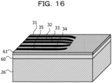
- FIGs. 10 to 19 are perspective views illustrating an example of a manufacturing process for the multiplexers.
- the multiplexer 13c illustrated in FIG. 8 can also be manufactured by a similar method.
- illustration of the optical waveguide 12a3 portion illustrated in FIG. 9 is omitted.
- the forming area of the optical waveguide 12a3 (and other optical waveguides of the waveguide unit 10b in FIG. 5 ) is masked.
- an insulating layer 60 and a mask material 61 are deposited on the semiconductor substrate 26 by, for example, the CVD method.
- SiO 2 is used as a base material of the optical waveguides 31 to 35 in FIG. 7
- an SiO 2 film is formed as the insulating layer 60.
- the insulating layer 60 is formed to have a thickness that matches the height of the already formed optical waveguides 12a 1 to 12a5 and 12b1 to 12b5 after removing the insulating layer 27 illustrated in FIG. 9 once, for example.
- the optical waveguides 31 to 35 are manufactured separately for each concentration of oxygen (or nitrogen) introduced by thermal nitridation, for example.
- the optical waveguide 33 with the highest nitrogen concentration is manufactured.
- an opening 61a is formed in the mask material 61 to expose a portion of the insulating layer 60 where the optical waveguide 33 is to be formed by patterning using the photolithographic technique or the EB technique ( FIG. 11 ).
- the optical waveguide 33 to be formed is appropriately aligned so that the light from the optical waveguide 12a3 of the waveguide unit 10b is introduced.
- the concentration of nitrogen to be mixed can be adjusted by adjusting a treatment temperature and a treatment time during the thermal nitridation, for example.
- openings 61b and 61c are formed in the mask material 61 by patterning for manufacturing the optical waveguides 32 and 34 with the second highest nitrogen concentration ( FIG. 13 ), and the optical waveguides 32 and 34 are formed by thermal nitridation ( FIG. 14 ).
- openings 61d and 61e are formed in the mask material 61 by patterning for manufacturing the optical waveguides 31 and 35 with the lowest nitrogen concentration (highest oxygen concentration) ( FIG. 15 ), and the optical waveguides 31 and 35 are formed by thermal nitridation ( FIG. 16 ).
- an opening 61f is formed in the mask material 61 by patterning for manufacturing the planar waveguide 36 ( FIG. 17 ), and the planar waveguide 36 is formed by thermal nitridation ( FIG. 18 ).
- the mask material 61 is removed by wet treatment using hot phosphoric acid (H 3 PO 4 ) or the like, for example, to complete the multiplexer 13a ( FIG. 19 ).
- hot phosphoric acid H 3 PO 4
- microwave pulse signal used for the state operation of the color center described above, it is desirable to consider the direction (polarization) of an electric field vector with respect to the axial direction (orientation) of the color center and an application direction of the static magnetic field.
- FIG. 20 is a diagram illustrating an example of the axial direction of the color center, the direction of the static magnetic field, and the direction of the electric field vector.
- FIG. 20 illustrates an example in which the axial direction of the color center (NV center) is formed parallel to a [111] plane of diamond, and the application direction of the static magnetic field (B) is also parallel to the axial direction of the color center.
- polarization is also taken into consideration for the laser for optical excitation as well.
- the ground level of the color center to be operated has a high linear polarization property in an optical transition (see, for example, FIG. 2 of Non-Patent Document 9 or the like). Therefore, it is important for the color center to adjust the polarization (linear polarization) of the laser to a direction in which absorption intensity and luminescence intensity associated with the absorption intensity can be increased.
- a half-wave plate or the like is used to adjust the polarization.
- FIG. 21 is a diagram illustrating an example of a quantum computer.
- a quantum computer 70 has the quantum circuit 10 illustrated in FIG. 5 and a control device 71.
- the control device 71 controls emission of the optical pulses from the laser light sources 16a and 16b, and performs processing based on the number of photons detected by the detectors 21a and 21b. More specifically, the control device 71 controls generation timing of the optical pulses of the laser by the laser light sources 16a and 16b of the quantum circuit 10, generation timing of the microwave pulse signals of the MW pulse signal generators (such as the MW pulse signal generators 14a1 to 14a5 in FIG. 1 ), and the like. Moreover, the control device 71 controls application timing of the magnetic field generators (such as the magnetic field generators 15a1 to 15a5 in FIG. 1 ) and the optical switches 18a1 to 18a5 and 18b1 to 18b5 in FIG. 5 .
- the control device 71 may perform these controls based on the number of detected photons (the presence or absence of photons) depending on the type of quantum calculation to be calculated (for example, in a case of performing quantum teleportation or the like, which will be described below).
- the control device 71 may include a processor that is hardware such as a central processing unit (CPU) or a digital signal processor (DSP). Furthermore, the control device 71 may include an electronic circuit for a special use, such as an application specific integrated circuit (ASIC) or a field programmable gate array (FPGA). Furthermore, the control device 71 may include a volatile memory such as a plurality of random access memories (RAMs) or a non-volatile memory such as a hard disk drive (HDD) or a flash memory. For example, the non-volatile memory stores a control program for controlling each part of the quantum circuit 10 according to the type of quantum calculation to be calculated. The control device 71 controls each part of the quantum circuit 10 and executes the quantum calculation by executing the control program.
- a processor that is hardware such as a central processing unit (CPU) or a digital signal processor (DSP). Furthermore, the control device 71 may include an electronic circuit for a special use, such as an application specific integrated circuit (ASIC) or a field programm
- FIG. 22 is a diagram illustrating an example of quantum calculation.
- FIG. 22 illustrates an example of a quantum teleportation circuit 80 that performs quantum teleportation, which is one type of quantum calculation.
- the quantum teleportation circuit 80 performs quantum calculation to transfer a state
- the quantum teleportation circuit 80 has Hadamard gates 81, 82, 84, and 86, controlled-NOT gates 83, 85, and 87, measurement gates 88 and 89, a Pauli X gate 90, and a Pauli Z gate 91.
- the quantum teleportation circuit 80 as described above can be implemented by using a total of three single-photon sources: two of the single-photon sources 11a1 to 11a5 and one of the single-photon sources 11b1 to 11b5 as qubits in the waveguide unit 10b illustrated in FIG. 5 , for example.
- a calculation procedure in the case of using the three qubits will be described, setting the qubit generated by the single-photon source 11a1 as qubit A1, the qubit generated by the single-photon source 11a2 as qubit A2, and the qubit generated by the single-photon source 11b1 as qubit B.
- the state of qubit A1 is assumed to be
- ⁇ > A is a linear combination of states
- c 0 and c 1 are predetermined coefficients.
- the control device 71 turns on the optical switches 18a2 and 18b1, turns off the other optical switches 18a1, 18a3 to 18a5, and 18b2 to 18b5, and causes the laser light sources 16a and 16b to generate the optical pulses for initialization.
- the center wavelength of the optical pulse for initialization is adjusted to 532 nm in the case of the NV center.
- the initial state of qubit A2 is denoted by
- the initial state of qubit B is denoted by
- the control device 71 causes the MW pulse signal generators provided in the qubits A2 and B to generate pulse signals ((n/2 pulses) pulses obtained by rotating the state vector of the qubit defined in a Bloch space around the x axis by 90°).
- Hadamard gates 81 and 82 are operated (Hadamard transform) for the qubits A2 and B, and the qubits A2 and B are in a superposed state of the state
- control device 71 causes the laser light sources 16a and 16b to generate the optical pulses for resonant excitation.
- the center wavelength of the optical pulse for resonant excitation is adjusted to 637 nm in the case of the NV center.
- the optical pulse for resonant excitation is emitted to the qubits A2 and B, and the beam splitter 20 operates the controlled-NOT gate 83. Thereby, the entanglement via photons is formed between the qubits A2 and B as described above.
- control device 71 turns on the optical switches 18a1 and 18b1 and turns off the other optical switches 18a2 to 18a5 and 18b2 to 18b5. Then, the control device 71 causes the MW pulse signal generator provided for the qubit B to generate the pulse signal (n/2 pulse) again. Thereby, the Hadamard gate 84 is operated (Hadamard transform) for the qubit B, and the qubit B becomes in the superposed state of the state
- control device 71 causes the laser light sources 16a and 16b to generate the optical pulses for resonant excitation.
- the optical pulse for resonant excitation is emitted to the qubits A1 and B, and the beam splitter 20 operates the controlled-NOT gate 85. Thereby, the entanglement via photons is formed between the qubits A1 and B.
- control device 71 causes the MW pulse signal generator provided for the qubit A1 to generate the pulse signal (n/2 pulse) again.
- the Hadamard gate 86 is operated (Hadamard transform) for the qubit A1, and the qubit A1 becomes in the superposed state of state
- control device 71 causes the laser light source 16a to generate the optical pulse for resonant excitation.
- the optical pulse is emitted to the qubit A1 after Hadamard transformation, and the state
- control device 71 turns on the optical switches 18a2 and 18b1 and turns off the other optical switches 18a1, 18a3 to 18a5, and 18b2 to 18b5 again. Then, the control device 71 causes the laser light sources 16a and 16b to generate the optical pulses for resonant excitation.
- the optical pulse for resonant excitation is emitted to the qubits A2 and B, and the beam splitter 20 operates the controlled-NOT gate 87. Thereby, the entanglement via photons is formed between the qubits A2 and B.
- control device 71 stops the generation of the optical pulses by the laser light source 16a of the laser light sources 16a and 16b, and detects the state
- control device 71 stops the generation of the optical pulses by the laser light source 16b, and causes the MW pulse signal generator provided for the qubit A2 to operate the Pauli X gate 90 or the Pauli Z gate 91 based on the detection results by the measurement gates 88 and 89.
- the control device 71 causes the MW pulse signal generator to operate neither the Pauli X gate 90 nor the Pauli Z gate 91.
- the control device 71 causes the MW pulse signal generator to operate the Pauli X gate 90.
- the operation of the Pauli X gate 90 is an operation to cause the MW pulse signal generator provided for the qubit A2 to generate pulses.
- the control device 71 causes the MW pulse signal generator to operate the Pauli Z gate 91 without allowing execution of the operation of the Pauli X gate 90.
- the operation of the Pauli Z-gate 91 is an operation to cause the MW pulse signal generator provided for the qubit A2 to generate ⁇ 2n pulses.
- the control device 71 causes the MW pulse signal generator to operate both the Pauli X gate 90 and the Pauli Z gate 91.
- the quantum teleportation is implemented using the quantum circuit 10 illustrated in FIG. 5 .
- FIG. 23 is a diagram illustrating an example of a quantum circuit according to a second embodiment.
- elements same as the elements of the quantum circuit 10 illustrated in FIG. 5 are denoted by the same reference signs.
- a quantum circuit 100 of the second embodiment includes an input unit 100a, a waveguide unit 100b, and an output unit 100c. Note that, in FIG. 23 , illustration of MW pulse signal generators and magnetic field generators is omitted.
- the input unit 100a does not have a configuration for supplying optical pulses to single-photon sources 11b1 to 11b5 illustrated in FIG. 5 .
- photons generated from the respective single-photon sources 11a1 to 11a5 are propagated to a multiplexer 13a or a multiplexer 13b through one of optical waveguides formed in two different layers.
- each of a plurality of optical waveguides coupled to the multiplexer 13a shares the single-photon source with one of a plurality of optical waveguides coupled to the multiplexer 13b.
- the optical waveguides 101a1, 101a2, ..., and 101a5 in FIG. 23 are formed in the upper layer-side layer and are coupled to the multiplexer 13a formed on the layer.
- the optical waveguides 101b1, 101b2, ..., and 101b5 in FIG. 23 are formed in the lower layer-side layer and are coupled to the multiplexer 13b formed on the layer.
- EO modulators 102a1, 102a2, ..., 102a5, and 102b1, 102b2, ..., 102b5, which are modulators using an electro-optic (EO) effect, are provided in the optical waveguides 101a1 to 101a5, and 101b1 to 101b5.
- the EO modulators 102a1 to 102a5 and 102b1 to 102b5 have a function of optical switches, and can switch which of the optical waveguides in the upper layer or the lower layer to use (whether to propagate the photons to the multiplexer 13a or 13b) under the control of the control device 71. Moreover, the EO modulators 102a1 to 102a5 and 102b1 to 102b5 have an advantage of less loss when a refractive index changes. Furthermore, the EO modulators 102a1 to 102a5 and 102b1 to 102b5 have a function to smooth branching to the upper layer and lower layer of the optical waveguides to increase or decrease only a real part of the refractive index.
- optical switch other than the EO modulator may be used.
- the configuration of the output unit 100c is the same as the configuration of the output unit 10c in FIG. 5 .
- quantum circuit 100 of the second embodiment effects similar to those of the quantum circuit 10 of the first embodiment can be obtained, and entanglement can be formed between qubits by adjacent color centers.
- the photons generated by the single-photon source 11a1 are propagated through the optical waveguide 101a1 in the upper layer and the multiplexer 13a and are introduced into a beam splitter 20 via a filter 19a.
- the photons generated by the single-photon source 11a2 are propagated through the optical waveguide 101b2 in the lower layer and the multiplexer 13b and are introduced into the beam splitter 20 via a filter 19b. Thereby, entanglement is formed between qubits of adjacent color centers contained in the single-photon sources 11a1 and 11a2 via the photons.
- FIG. 24 is a diagram illustrating an example of a quantum circuit according to a third embodiment.
- elements same as the elements of the quantum circuit 10 illustrated in FIG. 5 are denoted by the same reference signs.
- a quantum circuit 110 of the third embodiment includes a waveguide unit 100b and an output unit 100c. Note that, in FIG. 24 , illustration of MW pulse signal generators and magnetic field generators is omitted. These elements are arranged below respective single-photon sources 111a1, 111a2, ..., and 111a5, for example.
- An input unit for selecting one of the single-photon sources 111a1 to 111a5 and emitting an optical pulse for resonant excitation (or for initialization) to the selected single-photon source is also not illustrated.
- the optical pulses are emitted in a z-axis direction in FIG. 24 from above to the single-photon sources 111a1 to 111a5.
- the quantum circuit 110 has a configuration in which each of optical waveguides 112a1, 112a2, ..., and 112a5 coupled to the multiplexer 13a shares the single-photon source with one of optical waveguides 112b1, 112b2, ..., and 112b5 coupled to the multiplexer 13b.
- optical waveguides 112a1 to 112a5, and 112b1 to 112b5 are provided with EO modulators 113a1, 113a2, ..., 113a5, and 113b1, 113b2, ..., 113b5 that function as optical switches as described above. Note that an optical switch other than the EO modulator may be used.
- the configuration of the output unit 100c is the same as the configuration of the output unit 10c in FIG. 5 .
- quantum circuit 110 of the third embodiment effects similar to those of the quantum circuit 10 of the first embodiment can be obtained, and entanglement can be formed between qubits by adjacent color centers.
- the photons generated by the single-photon source 111a1 are propagated through the optical waveguide 112a1 and the multiplexer 13a and are introduced into a beam splitter 20 via a filter 19a.
- the photons generated by the single-photon source 111a2 are propagated through the optical waveguide 112b2 and the multiplexer 13b and are introduced into the beam splitter 20 via a filter 19b. Thereby, entanglement is formed between qubits of adjacent color centers contained in the single-photon sources 111a1 and 111a2 via the photons.
- the quantum circuit 110 forms the optical waveguides in the same layer (same plane), and thus can be manufactured by a relatively easy manufacturing process.
Landscapes
- Engineering & Computer Science (AREA)
- General Physics & Mathematics (AREA)
- Theoretical Computer Science (AREA)
- Physics & Mathematics (AREA)
- Mathematical Analysis (AREA)
- Computing Systems (AREA)
- Evolutionary Computation (AREA)
- Condensed Matter Physics & Semiconductors (AREA)
- Computational Mathematics (AREA)
- Mathematical Optimization (AREA)
- Pure & Applied Mathematics (AREA)
- Data Mining & Analysis (AREA)
- General Engineering & Computer Science (AREA)
- Mathematical Physics (AREA)
- Software Systems (AREA)
- Artificial Intelligence (AREA)
- Optical Integrated Circuits (AREA)
- Optical Modulation, Optical Deflection, Nonlinear Optics, Optical Demodulation, Optical Logic Elements (AREA)
Abstract
Description
- The present invention relates to a quantum circuit, a quantum computer, and a method of manufacturing a quantum circuit.
- In recent years, European and American information and communication technology (ICT) companies have been actively engaged in research and development of general-purpose quantum computers that can be used for various computational purposes. In 2014, a research group led by Martinis et al. at University of California, Santa Barbara (UCSB) established that high-fidelity gate operations and measurements were possible on a superconducting 5-qubit quantum computer (for example, See Non-Patent Document 1). After the research, there were reports of the start of commercial services using superconducting quantum computers and demonstration of quantum supremacy (for example, see Non-Patent Documents 2 and 3), and there are growing expectations for practical use of general-purpose quantum computers worldwide.
- However, from the results of previous research on computational algorithms for general-purpose computation, it is considered that 10,000 to 100,000,000 qubits are required to realize an error-tolerant quantum computer that can ensure the reliability of quantum chemical computations, quantum simulations, and computational results (for example, see Non-Patent Document 4). Considering that the current situation is about several tens of qubits, this is a significant expansion. A current mainstream superconducting method is poor in integration due to use of a huge cooling device (cryostat) using a 3He-4He dilution refrigerator to cool a device, even on a scale of at most 50 qubits. Moreover, a coherence time, which is a parameter that determines the number of operations per unit time of a system, is subject to physical constraints such as the order of µs, which is short. Furthermore, in a superconducting quantum computer, one qubit can only form entanglement (a bonded state between bits essential for quantum calculation) with four adjacent qubits (for example, see Non-Patent Document 3). Considering that the number of nodes that can form entanglement is a parameter that is directly linked to the computational performance of a quantum computer, this method lacks scalability.
- By the way, there is a diamond color center as one of quantum elements (hereinafter simply referred to as a color center). The color center is a type of complex defect that is formed with formation of vacancies when carbon (C) atoms that make up a base material are replaced by impurity atoms such as nitrogen (N) and silicon (Si) and its electronic system has spin (see, for example, Non-Patent Documents 5 and 6). The color center has a long coherence time on the order of milliseconds, reflecting strong bonds between the carbon atoms that make up diamond, even though it is a solid system. Moreover, the color center can be a single-photon source that can operate at room temperature using coherent control (quantum state control) of its electronic levels by microwaves and an optical transition process between the levels. Therefore, it is known that an electronic spin state can be read via photons by injecting resonant light with energy equal to the energy between the levels of the color center (see, for example, Non-Patent Document 7).
- Moreover, a ground state of the diamond color center is split into a fine structure due to crystal field interaction, interaction with an external magnetic field (called Zeeman effect), and interaction with atoms having nuclear spin such as 14N and 13C (hyperfine interaction) (see, for example, Patent Document 2 and Non-Patent Document 8). Therefore, the color center can transfer its own electronic spin state to nuclear spin via the hyperfine interaction. In general, electrons (spins) are disturbed by interactions with the environment, such as lattices, atoms with spins, and crystal defects, but the nuclear spin has a weak interaction with the environment and has resistance to disturbance, and thus has a coherence time on a min order. A spin system of the color center including the nuclear spin has high potential as a quantum register or qubit.
-
- Patent Document 1:
U.S. Patent Application Publication No. 2018/0114138 - Patent Document 2:
Japanese National Publication of International Patent Application No. 2015-504592 -
- Non-Patent Document 1: Jerry M. Chow et al, "Implementing a strand of a scalable fault-tolerant quantum computing fabric", (USA), June 24, 2014
- Non-Patent Document 2: "IBM is building the first universal quantum computer for business and science", [online], March 6, 2017, IBM, [searched on March 7, 2023], the Internet <URL: jp.newsroom.ibm.com/2017-03-06-IBM-Building-First-Universal-Quantum-Computers-for-Business-and-Science>
- Non-Patent Document 3: Frank Arute et al, "Quantum supremacy using a programmable superconducting processor", (USA), October 23, 2019
- Non-Patent Document 4: " Strategic Proposal Quantum Computer Science for All - Towards novel quantum applications -", Center for Research and Development Strategy, December 2018, CRDS-FY2018-SP-04, p. 21-22
- Non-Patent Document 5: Physical Review X, (USA), March 31, 2014, 4, 011057
- Non-Patent Document 6: Donggyu Kim et al, "CMOS-Integrated Diamond Nitrogen-Vacancy Quantum Sensor", (USA), October 2, 2018
- Non-Patent Document 7: John F. Barry et al, "Sensitivity Optimization for NV-Diamond Magnetometry", (USA), arxiv: 1903.08176v2, March 31, 2020
- Non-Patent Document 8: Marcus W. Doherty et al, "The nitrogen-vacancy colour centre in diamond', (USA), arXiv: 1905.02094v2, February 15, 2013
- Non-Patent Document 9: Nature Physics, (USA), November, 2005, Vol. 1, p. 94-98
- However, single photons emitted from the single-photon source including the color center or the like suffer a loss in a propagation space. Therefore, it has been difficult to scale up spatial arrangement of the single-photon source while ensuring high detection efficiency in a free-space optical system.
- In one aspect, an object of the present invention is to provide a quantum circuit, a quantum computer, and a method of manufacturing a quantum circuit that enable a large-scale quantum computer.
- In one embodiment, a quantum circuit is provided, which includes a plurality of first optical waveguides and a plurality of second optical waveguides formed on a substrate and each of which includes a single-photon source; a first multiplexer formed on the substrate and configured to condense first photons propagated through the plurality of first optical waveguides; a second multiplexer formed on the substrate and configured to condense second photons propagated through the plurality of second optical waveguides; a branching element configured to introduce the first photons condensed by the first multiplexer and the second photons condensed by the second multiplexer and branch the first photons and the second photons in a first direction or a second direction; and a first detector and a second detector configured to detect the first photons or the second photons branched in the first direction or the second direction.
- Furthermore, in one embodiment, a quantum computer is provided.
- Furthermore, in one embodiment, a method of manufacturing a quantum circuit is provided.
- According to an aspect of the embodiments, a quantum circuit includes a plurality of first optical waveguides and a plurality of second optical waveguides formed on a substrate and each of which includes a single-photon source; a first multiplexer formed on the substrate and configured to condense first photons propagated through the plurality of first optical waveguides; a second multiplexer formed on the substrate and configured to condense second photons propagated through the plurality of second optical waveguides; a branching element configured to introduce the first photons condensed by the first multiplexer and the second photons condensed by the second multiplexer and branch the first photons and the second photons in a first direction or a second direction; and a first detector and a second detector configured to detect the first photons or the second photons branched in the first direction or the second direction.
- In one aspect, the present invention enables provision of a large-scale quantum computer.
- The above-described object and other objects, features, and advantages of the present invention will become clear from the following description related to the accompanying drawings, which illustrate favorable embodiments as examples of the present invention.
-
-
FIG. 1 is a top view illustrating an example of a unit structure of a quantum circuit according to a first embodiment; -
FIG. 2 is a cross-sectional view taken along line II-II ofFIG. 1 ; -
FIG. 3 is a diagram illustrating an example of change in a quantum level at an NV center; -
FIG. 4 is a diagram illustrating an example of operation of an electronic spin state at the NV center and a method of reading the state; -
FIG. 5 is a top view illustrating an example of an overall structure of the quantum circuit of the first embodiment; -
FIG. 6 is a diagram illustrating formation of entanglement between color centers; -
FIG. 7 is a view illustrating a first example of a multiplexer; -
FIG. 8 is a view illustrating a second example of the multiplexer; -
FIG. 9 is a cross-sectional view illustrating an example of a manufacturing process for an optical waveguide including a single-photon source; -
FIG. 10 is a perspective view illustrating an example of a manufacturing process for a multiplexer (part 1); -
FIG. 11 is a perspective view illustrating an example of a manufacturing process for a multiplexer (part 2); -
FIG. 12 is a perspective view illustrating an example of a manufacturing process for a multiplexer (part 3); -
FIG. 13 is a perspective view illustrating an example of a manufacturing process for a multiplexer (part 4); -
FIG. 14 is a perspective view illustrating an example of a manufacturing process for a multiplexer (part 5); -
FIG. 15 is a perspective view illustrating an example of a manufacturing process for a multiplexer (part 6); -
FIG. 16 is a perspective view illustrating an example of a manufacturing process for a multiplexer (part 7); -
FIG. 17 is a perspective view illustrating an example of a manufacturing process for a multiplexer (part 8); -
FIG. 18 is a perspective view illustrating an example of a manufacturing process for a multiplexer (part 9); -
FIG. 19 is a perspective view illustrating an example of a manufacturing process for a multiplexer (part 10); -
FIG. 20 is a diagram illustrating an example of an axial direction of the color center, a direction of a static magnetic field, and a direction of an electric field vector; -
FIG. 21 is a diagram illustrating an example of a quantum computer; -
FIG. 22 is a diagram illustrating an example of quantum calculation; -
FIG. 23 is a diagram illustrating an example of a quantum circuit according to a second embodiment; -
FIG. 24 is a diagram illustrating an example of a quantum circuit according to a third embodiment; - Hereinafter, modes for carrying out the invention will be described with reference to the drawings.
-
FIG. 1 is a top view illustrating an example of a unit structure of a quantum circuit according to a first embodiment. - The unit structure of a
quantum circuit 10 includes a plurality of optical waveguides 12a1, 12a2, 12a3, 12a4, and 12a5 formed in an array and each including a single-photon source (one of single-photon sources 11a1, 11a2, 11a3, 11a4, and 11a5 inFIG. 1 ) and amultiplexer 13a. These elements are formed on the same substrate. Note that the number of optical waveguides is not limited to five, and may be six or more. - Hereinafter, description will be given on the assumption that the single-photon source includes the above-described color center, but the single-photon source is not limited to one including the color center, and other single-photon sources can be used. Other single-photon sources include, for example, a single-photon source including semiconductor quantum dots.
- The color center is a kind of complex defect formed by an impurity atom and a vacancy adjacent to the impurity atom in a diamond single crystal. The impurity atom is at least one of nitrogen (N), silicon (Si), germanium (Ge), tin (Sn) or lead (Pb).
FIG. 1 illustrates an example of the color center using nitrogen (hereinafter referred to as an NV center). V represents a vacancy and a black circle represents a carbon atom. - As the optical waveguides 12a1 to 12a5, for example, thin wire waveguides using aluminum nitride (AIN) or the like and having low propagation loss can be used.
- The
multiplexer 13a collects photons propagated through the optical waveguides 12a1 to 12a5. A specific example of themultiplexer 13a will be described below, but themultiplexer 13a can also be configured to reduce propagation loss. - Furthermore, in the example of
FIG. 1 , thequantum circuit 10 has MW pulse signal generators 14a1, 14a2, 14a3, 14a4, and 14a5 that individually provide microwave pulse signals to the respective single-photon sources 11a1 to 11a5. The microwave pulse signal is used to operate an electronic spin state of a complex defect (color center) that functions as a qubit. - Moreover, in the example of
FIG. 1 , thequantum circuit 10 has magnetic field generators 15a1, 15a2, 15a3, 15a4, and 15a5 that individually apply static magnetic fields to the respective single-photon sources 11a1 to 11a5. The static magnetic field causes Zeeman splitting, which will be described below. Note that the magnetic field generators do not have to be individually provided for the single-photon sources 11a1 to 11a5 as long as the single-photon source can form the color center with uniform Zeeman splitting widths of a ground level and an excitation level, and the magnetic field generator may apply a uniform static magnetic field as a whole. - The MW pulse signal generators 14a1 to 14a5 and the magnetic field generators 15a1 to 15a5 are arranged below the single-photon sources 11a1 to 11a5.
-
FIG. 2 is a cross-sectional view taken along line II-II ofFIG. 1 . -
FIG. 2 illustrates schematic shapes of the MW pulse signal generator 14a3, which is one of the MW pulse signal generators 14a1 to 14a5, and the magnetic field generator 15a3, which is one of the magnetic field generators 15a1 to 15a5. The MW pulse signal generator 14a3 and the magnetic field generator 15a3 have a loop shape and are formed in alayer 25. - A semiconductor substrate 26 (for example, a silicon substrate) is provided on the
layer 25, and the optical waveguide 12a3 including the single-photon source 11a3 and themultiplexer 13a are provided on thesemiconductor substrate 26 via an insulating layer 27 (for example, a silicon oxide film). The insulatinglayer 27 is formed to enhance adhesion of the optical waveguide 12a3 and themultiplexer 13a. -
FIG. 3 is a diagram illustrating an example of change in a quantum level at an NV center. - The NV center has s (spin quantum number) = 1, and has a ground triplet state 3A2 including a level of ms (magnetic quantum number) = 0 and two ground levels at which levels of ms = ±1 are degenerated, as illustrated in
FIG. 3 , due to crystal field splitting even in a case where no static magnetic field is applied. A frequency corresponding to energy between the two levels is about 2.88 GHz. In this state, in a case where the static magnetic field is applied in an axial direction of the NV center, the level degeneracy of ms = ±1 is resolved by Zeeman splitting, and the ground level becomes three levels. The frequency corresponding to the energy between the level of ms = +1 and the level of ms = -1 is about 0.1 GHz. Furthermore, at the NV center, each of the three levels is split into finer levels by interactions with atoms having nuclear spins such as 14N and 13C. That is, even finer levels are formed as the electronic spin state and the nuclear spin state are coupled with each other. The frequency corresponding to the energy of the level width where each of the three levels is split is about 0.005 GHz or less. - Note that although the change in the ground level has been given in the above description, a similar change is exhibited in an excited state.
-
FIG. 4 is a diagram illustrating an example of operation of the electronic spin state at the NV center and a method of reading the state.FIG. 4 illustrates the ground state (3A) and the excited state (3E) at the NV center after application of the static magnetic field. Note that, in both 3A and 3E ofFIG. 4 , the fine levels generated by interactions with nuclear spins are respectively collectively indicated by single lines for the three levels of ms = 0 and ±1. - The NV center contains, among the plurality of quantum levels in the electronic spin state and the nuclear spin state, two levels of two series having an energy difference between the levels is smaller than an energy line width of a laser to be emitted to the NV center, and the levels are close to an extent that the levels are able to be resonantly excited by the laser.
- In the present embodiment, the lowest ground level (the level of the state|↑>≡|0>) that is the level of ms = 0 and the second ground level (the level of the state |↓>≡|-1>) that is the level of ms = -1, which are the above-described two levels, are used as the levels of two states of the qubit. Note that it is also possible to use the lowest ground level that is the level of ms = 0 and the first ground level that is the level of ms = +1 as the levels of two states of the qubit.
- Furthermore,
FIG. 4 illustrates a graph illustrating Rabi oscillation. The horizontal axis represents Ωt (Ω is the frequency of the Rabi oscillation and t is a time), and the vertical axis represents a probability that an electron is in the |↑> state. - For example, a microwave pulse signal whose pulse width satisfies t = (n/2)/Ω is applied to a certain NV center, and resonant excitation is performed between two levels |↑> and |↓>, so that a superposed state (1/√/2)(|↑>+|↓>)) of |↑> and |↓> can be obtained. This operation corresponds to Hadamard transform, which is one of quantum gate operations.
- The MW pulse signal generators 14a1 to 14a5 illustrated in
FIG. 1 are used to, for example, operate the electronic spin states as described above for the respective single-photon sources 11a1 to 11a5. - The state obtained by operating the electronic spin state as described above can be read according to the presence or absence of luminescence produced by applying an optical pulse (laser) with energy equal to the energy difference between the ground and excitation levels (3E - 3A) to the NV center. In the case of the NV center, the wavelength corresponding to the above energy difference is 637 nm.
- In the case where the electron at the NV center is in the |↑> state (at the level of ms = 0), luminescence (relaxation luminescence) occurs when the optical pulse with energy equal to the above energy difference is given to the NV center. Meanwhile, in a case where the electron at the NV center is in the |↓> state (in the level of ms = -1), non-radiative relaxation without luminescence occurs when the optical pulse with energy equal to the above energy difference is given to the NV center. The presence or absence of luminescence (the presence or absence of photons) is detected by a detector to be described below via the optical waveguides 12a1 to 12a5, the
multiplexer 13a, and the like. -
FIG. 5 is a top view illustrating an example of an overall structure of the quantum circuit of the first embodiment. - The
quantum circuit 10 includes aninput unit 10a, awaveguide unit 10b, and anoutput unit 10c. - Two unit structures illustrated in
FIG. 1 are provided in thewaveguide unit 10b. In other words,waveguide unit 10b has another unit structure in addition to the unit structure illustrated inFIG. 1 . The another unit structure includes a plurality of optical waveguides 12b1, 12b2, 12b3, 12b4, and 12b5 formed in an array and each including a single-photon source (one of single-photon sources 11b1, 11b2, 11b3, 11b4, and 11b5 inFIG. 3 ) and amultiplexer 13b. Note that although illustration is omitted inFIG. 5 , MW pulse signal generators and magnetic field generators are respectively arranged below the single-photon sources 11a1 to 11a5 and 11b1 to 11b5, similarly toFIG. 1 . - The optical waveguides 12b1 to 12b5 and the
multiplexer 13b of thewaveguide unit 10b are formed on thesemiconductor substrate 26 illustrated inFIG. 2 , similarly to the optical waveguides 12a1 to 12a5 and themultiplexer 13a. Thereby, thewaveguide unit 10b is implemented by one chip. Note that theinput unit 10a and theoutput unit 10c may also be formed on thesemiconductor substrate 26. - The
input unit 10a selects one of the single-photon sources 11a1 to 11a5 and one of the single-photon sources 11b1 to 11b5, and emits an optical pulse for resonant excitation (or initialization) to the selected single-photon source via the optical waveguide. Theinput unit 10a haslaser light sources input unit 10a has optical switches 18a1, 18a2, 18a3, 18a4, 18a5, 18b1, 18b2, 18b3, 18b4, and 18b5. - Each of the
laser light sources laser light sources - A center wavelength of the optical pulse for resonant excitation is adjusted to 637 nm corresponding to the above-described energy difference in the case of the NV center. The center wavelength of the optical pulse for initialization is adjusted to 532 nm in the case of the NV center. In the case where the optical pulse for initialization is given to the NV center, the state of the electron drops to the level of ms = 0 and is initialized to the state |↑> through relaxation process after excitation even at the level of ms = 0 or the level of ms = ±1.
- The optical pulse generated by the
laser light source 16a is introduced into the optical waveguides 12a1 to 12a5 of thewaveguide unit 10b via the optical waveguides 17a1 to 17a5 and the optical switches 18a1 to 18a5. The optical pulse generated by thelaser light source 16b is introduced into the optical waveguides 12b1 to 12b5 of thewaveguide unit 10b via the optical waveguides 17b1 to 17b5 and the optical switches 18b1 to 18b5. - For the optical switches 18a1 to 18a5 and 18b1 to 18b5, for example, EA modulators using an electro-absorption (EA) effect can be used. When a reverse bias voltage is applied to the EA modulator, the amount of light absorbed increases and no light is transmitted. Therefore, it is possible to switch whether to introduce the optical pulses generated by the
laser light sources - Note that the
input unit 10a may be configured to emit the optical pulses in a z-axis direction inFIG. 5 from above the single-photon sources 11a1 to 11a5 and 11b1 to 11b5. - The
output unit 10c hasfilters beam splitter 20 that is an example of a branching element, anddetectors - The light output from the
multiplexer 13a is introduced into thebeam splitter 20 through thefilter 19a, and the light output from themultiplexer 13b is respectively introduced into thebeam splitter 20 through thefilter 19b. - Although the
filters multiplexers - Note that, in a case of using the color center (with a spin quantum number of s = 1/2) using silicon, germanium, tin, or lead as an impurity, relaxation luminescence between the excitation level and the ground level due to optical excitation has different wavelength components depending on the level of the ground state in which the electron is present. The wavelength difference between these wavelength components is generally smaller than energy resolution of the
detectors filters - In the case of using the color center using silicon, germanium, tin, or lead as an impurity, the relaxation luminescence via phonons can be suppressed even at room temperature and thus operation performance at the room temperature is higher than a case of using the color center using nitrogen as an impurity.
- For example, a Fabry-Perot interferometer or the like can be used as the
filters - The
beam splitter 20 introduces the photons condensed by themultiplexer 13a and the photons condensed by themultiplexer 13b, and splits the photons in a first direction or a second direction. In thebeam splitter 20, the first direction and the second direction are orthogonal, and probabilities of branching into the first direction and into the second direction are both 50% (50:50 orthogonal configuration), respectively. Thebeam splitter 20 is, for example, a half mirror that divides the amount of transmitted light and the amount of reflected light approximately 1:1. The photons introduced from themultiplexer 13a strike one surface of the half mirror and are reflected or transmitted, and the photons introduced from themultiplexer 13b strike another surface of the half mirror and are reflected or transmitted. - The
detector 21a detects the photons that are incident from one surface of the half mirror and are reflected, or the photons that are incident from the other surface of the half mirror and are transmitted. Thedetector 21b detects the photons that are incident from the other surface of the half mirror and are reflected, or the photons that are incident from one surface of the half mirror and are transmitted. As thedetectors - In the
quantum circuit 10 as illustrated inFIG. 5 , the photon propagated through any of the optical waveguides 12a1 to 12a5 and the photon propagated through any of the optical waveguides 12b1 to 12b5 merge at thebeam splitter 20, resulting in formation of two-photon correlation. This allows formation of entanglement between different color centers indirectly via photons. -
FIG. 6 is a diagram illustrating formation of entanglement between color centers. -
FIG. 6 illustrates an example using the NV center as the color center. An NV center A is the NV center included in any of the single-photon sources 11a 1 to 11a5 inFIG. 5 , and an NV center B is the NV center included in any of the single-photon sources 11b1 to 11b5 inFIG. 5 . - A microwave pulse signal as described above is given, and the NV centers A and B are respectively in the superposed state of |↑> and |↓>. In this state, when the optical pulses with the center wavelength of 637 nm generated by the
laser light sources beam splitter 20. Thereby, two qubits by the NV centers A and B indirectly become in an entangled state. This operation corresponds to an operation of a controlled-NOT gate, which is one of quantum gate operations. - In the
quantum circuit 10 as described above, the optical waveguides 12a1 to 12a5 and 12b1 to 12b5 including the single-photon sources 11a1 to 11a5 and 11b1 to 11b5 are arranged in an array on the same substrate, and themultiplexers - Furthermore, in the example of
FIG. 5 , the entanglement can be generated with 5 × 5 combinations between the qubit by any of the single-photon sources 11a1 to 11a5 and the qubit by any of the single-photon sources 11b1 to 11b5, without restriction between adjacent qubits. The combinations can be further increased by the configuration of themultiplexers quantum circuit 10. Therefore, calculation cost can be significantly reduced. -
FIG. 7 is a view illustrating a first example of the multiplexer. AlthoughFIG. 7 illustrates an example of themultiplexer 13a illustrated inFIG. 5 , themultiplexer 13b can also have a similar configuration. - The
multiplexer 13a has theoptical waveguides planar waveguide 36 that guides the photons propagated through theoptical waveguides 31 to 35 into an output terminal of themultiplexer 13a. - The
optical waveguides 31 to 35 arranged outer side are bent more outwardly so that they are coupled at right angles to a circular arc of theplanar waveguide 36. To compensate for an optical path difference between the optical waveguides 12a1 to 12a5 (between input ports of themultiplexer 13a) and to reduce a propagation loss due to reflection of photons in theoptical waveguides 31 to 35, it is desirable to refract the photons incident from the optical waveguides 12a1 to 12a5 according to the degrees of bending of theoptical waveguides 31 to 35. - Therefore, the
optical waveguides 31 to 35 have a lower refractive index than the optical waveguides 12a1 to 12a5, and theoptical waveguides 31 to 35 located closer to a center side have a higher refractive index. For example, in a case where the optical waveguides 12a1 to 12a5 are formed using aluminum nitride (AIN) (the refractive index: 2.2), theoptical waveguides 31 to 35 are formed using silicon oxynitride (SiON) (the refractive index: 1.85). The refractive index of SiON can be changed by changing a composition ratio of oxygen and nitrogen. The refractive index approaches the refractive index of SiO2 = 1.45 as the concentration of oxygen becomes higher. The refractive index approaches the refractive index of silicon nitride (SiN) = 1.95 as the concentration of nitrogen becomes higher. The outer optical waveguides (for example, theoptical waveguides optical waveguide 33, or the like), which are set to have a higher refractive index, is formed with a higher concentration of nitrogen. - The fan-shaped
planar waveguide 36 propagates the photons incident from theoptical waveguides 31 to 35 coupled to the circular arc to the output terminal of themultiplexer 13a located at a central angle of the fan. Theplanar waveguide 36 is formed using, for example, SiON having a uniform composition. - For example, the number of ports can be at least 10 in a case where lengths of the
multiplexer 13a in x-axis and y-axis directions inFIG. 7 are 30 µm, a waveguide diameter of the optical waveguides 12a1 to 12a5 is 0.5 µm, a waveguide interval is 3 µm, and an angle between adjacent optical paths at a central angle portion of theplanar waveguide 36 is 5°. That is, five optical waveguides can be further added in addition to the five optical waveguides 12a1 to 12a5. In this case, the length of thewaveguide unit 10b in the x-axis direction illustrated inFIG. 5 may be, for example, about 400 µm, and the length in the y-axis direction may be, for example, about 100 µm. - Thereby, 10 × 10 = 100 types of entanglement between color centers can be generated by two-photon correlation by photons respectively output from the
multiplexers multiplexers - Note that it is conceivable that the length of the
waveguide unit 10b in the z-axis direction (the thickness of the structure inFIG. 2 ) is, for example, about 500 µm. -
FIG. 8 is a view illustrating a second example of the multiplexer. AlthoughFIG. 8 illustrates an example of amultiplexer 13c instead of themultiplexer 13a illustrated inFIG. 5 , themultiplexer 13b can also have a similar configuration. - The
multiplexer 13c illustrated inFIG. 8 also hasoptical waveguides planar waveguide 46, similarly to themultiplexer 13a illustrated inFIG. 7 . Note that, unlike themultiplexer 13a, themultiplexer 13c has an acute triangular shape in which the length in the x-axis direction inFIG. 8 is longer than the length in the y-axis direction. Thereby, a bending curvature of theoptical waveguides 41 to 45 can be moderated, and the loss at a connection portion to theplanar waveguide 46 can be reduced. - An example of a method of manufacturing the
quantum circuit 10 will be described below. -
FIG. 9 is a cross-sectional view illustrating an example of a manufacturing process for an optical waveguide including a single-photon source. Note that, inFIG. 9 , illustration of thelayer 25 illustrated inFIG. 2 in which the MW pulse signal generators 14a1 to 14a5 and the magnetic field generators 15a1 to 15a5 are formed is omitted. - The insulating layer 27 (for example, an SiO2 film) is formed on the semiconductor substrate 26 (for example, a silicon substrate) by, for example, a chemical vapor deposition (CVD) method. Then, the optical waveguide 12a3 including the single-photon source 11a3 (and other optical waveguides of the
waveguide unit 10b inFIG. 5 ) is formed on the insulatinglayer 27. - For example, the single-photon source 11a3 using diamond containing the NV center can be formed by doping n-type impurities such as phosphorus (P) atoms during vapor phase growth of diamond by the CVD method. In the optical waveguide 12a3, for example, AIN is used as a material for the thin wire waveguide portion that propagates the photons generated from the single-photon source 11a3 to the
multiplexer 13a. The thin wire waveguide portion is patterned using a photolithographic technique or an electron beam (EB) technique while masking amultiplexer forming area 50 with amask material 51 In patterning, SiN having heat resistance is used as themask material 51, for example. - Thereafter, the manufacturing process for the
multiplexers -
FIGs. 10 to 19 are perspective views illustrating an example of a manufacturing process for the multiplexers. Hereinafter, an example of the method of manufacturing themultiplexer 13a illustrated inFIG. 7 will be described but themultiplexer 13c illustrated inFIG. 8 can also be manufactured by a similar method. Note that, inFIGs. 10 to 19 , illustration of the optical waveguide 12a3 portion illustrated inFIG. 9 is omitted. When forming themultiplexers waveguide unit 10b inFIG. 5 ) is masked. - As illustrated in
FIG. 10 , an insulatinglayer 60 and amask material 61 are deposited on thesemiconductor substrate 26 by, for example, the CVD method. In the example illustrated below, it is assumed that SiO2 is used as a base material of theoptical waveguides 31 to 35 inFIG. 7 , and an SiO2 film is formed as the insulatinglayer 60. The insulatinglayer 60 is formed to have a thickness that matches the height of the already formedoptical waveguides 12a 1 to 12a5 and 12b1 to 12b5 after removing the insulatinglayer 27 illustrated inFIG. 9 once, for example. - The
optical waveguides 31 to 35 are manufactured separately for each concentration of oxygen (or nitrogen) introduced by thermal nitridation, for example. For example, first, theoptical waveguide 33 with the highest nitrogen concentration is manufactured. In that case, anopening 61a is formed in themask material 61 to expose a portion of the insulatinglayer 60 where theoptical waveguide 33 is to be formed by patterning using the photolithographic technique or the EB technique (FIG. 11 ). Note that, in the patterning, theoptical waveguide 33 to be formed is appropriately aligned so that the light from the optical waveguide 12a3 of thewaveguide unit 10b is introduced. The same similarly applies to the patterning of theoptical waveguides - Then, the exposed portion of the insulating
layer 60 is subjected to thermal nitridation to form the optical waveguide 33 (FIG. 12 ). The concentration of nitrogen to be mixed can be adjusted by adjusting a treatment temperature and a treatment time during the thermal nitridation, for example. - Next,
openings mask material 61 by patterning for manufacturing theoptical waveguides FIG. 13 ), and theoptical waveguides FIG. 14 ). - Thereafter,
openings mask material 61 by patterning for manufacturing theoptical waveguides FIG. 15 ), and theoptical waveguides FIG. 16 ). - Then, an
opening 61f is formed in themask material 61 by patterning for manufacturing the planar waveguide 36 (FIG. 17 ), and theplanar waveguide 36 is formed by thermal nitridation (FIG. 18 ). - Thereafter, the
mask material 61 is removed by wet treatment using hot phosphoric acid (H3PO4) or the like, for example, to complete themultiplexer 13a (FIG. 19 ). - Note that, for the microwave pulse signal used for the state operation of the color center described above, it is desirable to consider the direction (polarization) of an electric field vector with respect to the axial direction (orientation) of the color center and an application direction of the static magnetic field.
-
FIG. 20 is a diagram illustrating an example of the axial direction of the color center, the direction of the static magnetic field, and the direction of the electric field vector. -
FIG. 20 illustrates an example in which the axial direction of the color center (NV center) is formed parallel to a [111] plane of diamond, and the application direction of the static magnetic field (B) is also parallel to the axial direction of the color center. - The (directions of) spins at the ground levels (ms = 0 and ms = -1) of the color center to be operated are different. Therefore, to perform the state operation between ms = 0 and ms = -1, a wave number vector k of the microwave pulse signal is set to be parallel to the axial direction of the NV center and the application direction of the static magnetic field B, and the electric field is set to have linear polarization (σ±), according to the transition selection rule (the law of conservation of angular momentum). The same similarly applies to other color centers (spin quantum number s = 1/2).
- Furthermore, polarization is also taken into consideration for the laser for optical excitation as well. The ground level of the color center to be operated has a high linear polarization property in an optical transition (see, for example,
FIG. 2 of Non-Patent Document 9 or the like). Therefore, it is important for the color center to adjust the polarization (linear polarization) of the laser to a direction in which absorption intensity and luminescence intensity associated with the absorption intensity can be increased. A half-wave plate or the like is used to adjust the polarization. -
FIG. 21 is a diagram illustrating an example of a quantum computer. - A
quantum computer 70 has thequantum circuit 10 illustrated inFIG. 5 and acontrol device 71. - The
control device 71 controls emission of the optical pulses from thelaser light sources detectors control device 71 controls generation timing of the optical pulses of the laser by thelaser light sources quantum circuit 10, generation timing of the microwave pulse signals of the MW pulse signal generators (such as the MW pulse signal generators 14a1 to 14a5 inFIG. 1 ), and the like. Moreover, thecontrol device 71 controls application timing of the magnetic field generators (such as the magnetic field generators 15a1 to 15a5 inFIG. 1 ) and the optical switches 18a1 to 18a5 and 18b1 to 18b5 inFIG. 5 . Thecontrol device 71 may perform these controls based on the number of detected photons (the presence or absence of photons) depending on the type of quantum calculation to be calculated (for example, in a case of performing quantum teleportation or the like, which will be described below). - The
control device 71 may include a processor that is hardware such as a central processing unit (CPU) or a digital signal processor (DSP). Furthermore, thecontrol device 71 may include an electronic circuit for a special use, such as an application specific integrated circuit (ASIC) or a field programmable gate array (FPGA). Furthermore, thecontrol device 71 may include a volatile memory such as a plurality of random access memories (RAMs) or a non-volatile memory such as a hard disk drive (HDD) or a flash memory. For example, the non-volatile memory stores a control program for controlling each part of thequantum circuit 10 according to the type of quantum calculation to be calculated. Thecontrol device 71 controls each part of thequantum circuit 10 and executes the quantum calculation by executing the control program. -
FIG. 22 is a diagram illustrating an example of quantum calculation.FIG. 22 illustrates an example of aquantum teleportation circuit 80 that performs quantum teleportation, which is one type of quantum calculation. - The
quantum teleportation circuit 80 performs quantum calculation to transfer a state |ψ>A to a distant location (to a different qubit) using the effect of the above-describe entanglement. Thequantum teleportation circuit 80 hasHadamard gates NOT gates measurement gates Pauli X gate 90, and aPauli Z gate 91. - The
quantum teleportation circuit 80 as described above can be implemented by using a total of three single-photon sources: two of the single-photon sources 11a1 to 11a5 and one of the single-photon sources 11b1 to 11b5 as qubits in thewaveguide unit 10b illustrated inFIG. 5 , for example. Hereinafter, a calculation procedure in the case of using the three qubits will be described, setting the qubit generated by the single-photon source 11a1 as qubit A1, the qubit generated by the single-photon source 11a2 as qubit A2, and the qubit generated by the single-photon source 11b1 as qubit B. - The state of qubit A1 is assumed to be |ψ>A. |ψ>A is a linear combination of states |0> and |-1>, and can be expressed as c0|0> + c1|-1>. c0 and c1 are predetermined coefficients.
- First, the
control device 71 causes the magnetic field generators to apply static magnetic fields to the qubits A1, A2, and B, respectively. Thereby, the degeneracy of the level of ms = ±1 is resolved, and the level is split into two levels of ms = -1 and ms = +1 (seeFIG. 3 ). - Next, the
control device 71 turns on the optical switches 18a2 and 18b1, turns off the other optical switches 18a1, 18a3 to 18a5, and 18b2 to 18b5, and causes thelaser light sources FIG. 22 , the initial state of qubit A2 is denoted by |0>A, and the initial state of qubit B is denoted by |0>B. - After that, the
control device 71 causes the MW pulse signal generators provided in the qubits A2 and B to generate pulse signals ((n/2 pulses) pulses obtained by rotating the state vector of the qubit defined in a Bloch space around the x axis by 90°). Thereby,Hadamard gates - Moreover, the
control device 71 causes thelaser light sources beam splitter 20 operates the controlled-NOT gate 83. Thereby, the entanglement via photons is formed between the qubits A2 and B as described above. - Next, the
control device 71 turns on the optical switches 18a1 and 18b1 and turns off the other optical switches 18a2 to 18a5 and 18b2 to 18b5. Then, thecontrol device 71 causes the MW pulse signal generator provided for the qubit B to generate the pulse signal (n/2 pulse) again. Thereby, theHadamard gate 84 is operated (Hadamard transform) for the qubit B, and the qubit B becomes in the superposed state of the state |0> and the state |-1> again. - Thereafter, the
control device 71 causes thelaser light sources beam splitter 20 operates the controlled-NOT gate 85. Thereby, the entanglement via photons is formed between the qubits A1 and B. - Then, the
control device 71 causes the MW pulse signal generator provided for the qubit A1 to generate the pulse signal (n/2 pulse) again. Thereby, theHadamard gate 86 is operated (Hadamard transform) for the qubit A1, and the qubit A1 becomes in the superposed state of state |0> and state |-1>. - Thereafter, the
control device 71 causes thelaser light source 16a to generate the optical pulse for resonant excitation. The optical pulse is emitted to the qubit A1 after Hadamard transformation, and the state |0> or |-1> of the qubit A1 is detected as the presence or absence of photons by thedetectors measurement gate 88. - Next, the
control device 71 turns on the optical switches 18a2 and 18b1 and turns off the other optical switches 18a1, 18a3 to 18a5, and 18b2 to 18b5 again. Then, thecontrol device 71 causes thelaser light sources beam splitter 20 operates the controlled-NOT gate 87. Thereby, the entanglement via photons is formed between the qubits A2 and B. - Thereafter, the
control device 71 stops the generation of the optical pulses by thelaser light source 16a of thelaser light sources detectors measurement gate 89. - Then, the
control device 71 stops the generation of the optical pulses by thelaser light source 16b, and causes the MW pulse signal generator provided for the qubit A2 to operate thePauli X gate 90 or thePauli Z gate 91 based on the detection results by themeasurement gates - In a case where the detection result is |00> (in a case where the detection results by the
measurement gates control device 71 causes the MW pulse signal generator to operate neither thePauli X gate 90 nor thePauli Z gate 91. In a case where the detection result is |0-1> (in a case where the detection result by themeasurement gate 88 is the state |0> and the detection result by themeasurement gate 89 is the state |-1>), thecontrol device 71 causes the MW pulse signal generator to operate thePauli X gate 90. The operation of thePauli X gate 90 is an operation to cause the MW pulse signal generator provided for the qubit A2 to generatepulses. In a case where the detection result is |-10> (in a case where the detection result by the
measurement gate 88 is the state |-1> and the detection result by themeasurement gate 89 is the state |0>), thecontrol device 71 causes the MW pulse signal generator to operate thePauli Z gate 91 without allowing execution of the operation of thePauli X gate 90. The operation of thePauli Z-gate 91 is an operation to cause the MW pulse signal generator provided for the qubit A2 to generate ±2n pulses. In a case where the detection result is |-1-1> (both the detection results by themeasurement gates control device 71 causes the MW pulse signal generator to operate both thePauli X gate 90 and thePauli Z gate 91. - Thereby, the state |ψ>A of the qubit A1 is transferred to the qubit A2.
- As described above, the quantum teleportation is implemented using the
quantum circuit 10 illustrated inFIG. 5 . -
FIG. 23 is a diagram illustrating an example of a quantum circuit according to a second embodiment. InFIG. 23 , elements same as the elements of thequantum circuit 10 illustrated inFIG. 5 are denoted by the same reference signs. - A
quantum circuit 100 of the second embodiment includes aninput unit 100a, awaveguide unit 100b, and anoutput unit 100c. Note that, inFIG. 23 , illustration of MW pulse signal generators and magnetic field generators is omitted. - Unlike the
input unit 10a of thequantum circuit 10 illustrated inFIG. 5 , theinput unit 100a does not have a configuration for supplying optical pulses to single-photon sources 11b1 to 11b5 illustrated inFIG. 5 . - In the
waveguide unit 100b, photons generated from the respective single-photon sources 11a1 to 11a5 are propagated to amultiplexer 13a or amultiplexer 13b through one of optical waveguides formed in two different layers. In other words, each of a plurality of optical waveguides coupled to themultiplexer 13a shares the single-photon source with one of a plurality of optical waveguides coupled to themultiplexer 13b. - For example, the optical waveguides 101a1, 101a2, ..., and 101a5 in
FIG. 23 are formed in the upper layer-side layer and are coupled to themultiplexer 13a formed on the layer. The optical waveguides 101b1, 101b2, ..., and 101b5 inFIG. 23 are formed in the lower layer-side layer and are coupled to themultiplexer 13b formed on the layer. - Furthermore, EO modulators 102a1, 102a2, ..., 102a5, and 102b1, 102b2, ..., 102b5, which are modulators using an electro-optic (EO) effect, are provided in the optical waveguides 101a1 to 101a5, and 101b1 to 101b5.
- The EO modulators 102a1 to 102a5 and 102b1 to 102b5 have a function of optical switches, and can switch which of the optical waveguides in the upper layer or the lower layer to use (whether to propagate the photons to the
multiplexer control device 71. Moreover, the EO modulators 102a1 to 102a5 and 102b1 to 102b5 have an advantage of less loss when a refractive index changes. Furthermore, the EO modulators 102a1 to 102a5 and 102b1 to 102b5 have a function to smooth branching to the upper layer and lower layer of the optical waveguides to increase or decrease only a real part of the refractive index. - Note that an optical switch other than the EO modulator may be used.
- The configuration of the
output unit 100c is the same as the configuration of theoutput unit 10c inFIG. 5 . - According to the
quantum circuit 100 of the second embodiment, effects similar to those of thequantum circuit 10 of the first embodiment can be obtained, and entanglement can be formed between qubits by adjacent color centers. - For example, consider a case where optical pulses for resonant excitation are emitted to the single-photon sources 11a1 and 11a2, and the optical switches by the EO modulators 102a1 and 102b2 are turned on and the optical switches by the EO modulators 102b1 and 102a2 are turned off under the control of the
control device 71. In this case, the photons generated by the single-photon source 11a1 are propagated through the optical waveguide 101a1 in the upper layer and themultiplexer 13a and are introduced into abeam splitter 20 via afilter 19a. Meanwhile, the photons generated by the single-photon source 11a2 are propagated through the optical waveguide 101b2 in the lower layer and themultiplexer 13b and are introduced into thebeam splitter 20 via afilter 19b. Thereby, entanglement is formed between qubits of adjacent color centers contained in the single-photon sources 11a1 and 11a2 via the photons. -
FIG. 24 is a diagram illustrating an example of a quantum circuit according to a third embodiment. InFIG. 24 , elements same as the elements of thequantum circuit 10 illustrated inFIG. 5 are denoted by the same reference signs. - A
quantum circuit 110 of the third embodiment includes awaveguide unit 100b and anoutput unit 100c. Note that, inFIG. 24 , illustration of MW pulse signal generators and magnetic field generators is omitted. These elements are arranged below respective single-photon sources 111a1, 111a2, ..., and 111a5, for example. - An input unit for selecting one of the single-photon sources 111a1 to 111a5 and emitting an optical pulse for resonant excitation (or for initialization) to the selected single-photon source is also not illustrated. In the
quantum circuit 110 of the third embodiment, the optical pulses are emitted in a z-axis direction inFIG. 24 from above to the single-photon sources 111a1 to 111a5. - In the
waveguide unit 100b, photons generated from each of the single-photon sources 111a1 to 111a5 are propagated through either of two different optical waveguides formed in the same layer (same plane) to amultiplexer 13a or amultiplexer 13b. In other words, thequantum circuit 110 has a configuration in which each of optical waveguides 112a1, 112a2, ..., and 112a5 coupled to themultiplexer 13a shares the single-photon source with one of optical waveguides 112b1, 112b2, ..., and 112b5 coupled to themultiplexer 13b. - Furthermore, the optical waveguides 112a1 to 112a5, and 112b1 to 112b5 are provided with EO modulators 113a1, 113a2, ..., 113a5, and 113b1, 113b2, ..., 113b5 that function as optical switches as described above. Note that an optical switch other than the EO modulator may be used.
- The configuration of the
output unit 100c is the same as the configuration of theoutput unit 10c inFIG. 5 . - According to the
quantum circuit 110 of the third embodiment, effects similar to those of thequantum circuit 10 of the first embodiment can be obtained, and entanglement can be formed between qubits by adjacent color centers. - For example, consider a case where optical pulses for resonant excitation are emitted to the single-photon sources 111a1 and 111a2, and the optical switches by the EO modulators 113a1 and 113b2 are turned on and the optical switches by the EO modulators 113b1 and 113a2 are turned off under the control of the
control device 71. In this case, the photons generated by the single-photon source 111a1 are propagated through the optical waveguide 112a1 and themultiplexer 13a and are introduced into abeam splitter 20 via afilter 19a. Meanwhile, the photons generated by the single-photon source 111a2 are propagated through the optical waveguide 112b2 and themultiplexer 13b and are introduced into thebeam splitter 20 via afilter 19b. Thereby, entanglement is formed between qubits of adjacent color centers contained in the single-photon sources 111a1 and 111a2 via the photons. - Furthermore, unlike the
quantum circuit 100 of the second embodiment, thequantum circuit 110 forms the optical waveguides in the same layer (same plane), and thus can be manufactured by a relatively easy manufacturing process. - The above description merely indicates the principle of the present invention. Moreover, numerous modifications and changes can be made by those skilled in the art. The present invention is not limited to the exact configuration and application examples illustrated and described above, and all corresponding modifications and equivalents are regarded within the scope of the present invention by appended claims and equivalents thereof.
-
- 10Quantum circuit
- 10aInput unit
- 10bWaveguide unit
- 10cOutput unit
- 11a1 to 11a5, 11b1 to 11b5Single-photon source
- 12a1 to 12a5, 12b1 to 12b5, 17a1 to 17a5, 17b1 to 17b5Optical waveguide
- 13a, 13bMultiplexer
- 14a1 to 14a5MW pulse signal generator
- 15a1 to 15a5Magnetic field generator
- 16a, 16bLaser light source
- 18a1 to 18a5, 18b1 to 18b5Optical switch
- 19a, 19bFilter
- 20Beam splitter
- 21a, 21bDetector
Claims (14)
- A quantum circuit comprising:a plurality of first optical waveguides and a plurality of second optical waveguides formed on a substrate and each of which includes a single-photon source;a first multiplexer formed on the substrate and configured to condense first photons propagated through the plurality of first optical waveguides;a second multiplexer formed on the substrate and configured to condense second photons propagated through the plurality of second optical waveguides;a branching element configured to introduce the first photons condensed by the first multiplexer and the second photons condensed by the second multiplexer and branch the first photons and the second photons in a first direction or a second direction; anda first detector and a second detector configured to detect the first photons or the second photons branched in the first direction or the second direction.
- The quantum circuit according to claim 1, wherein the single-photon source includes a complex defect formed by an impurity atom in a diamond single crystal and a vacancy adjacent to the impurity atom.
- The quantum circuit according to claim 2, wherein the impurity atom is at least one of nitrogen (N), silicon (Si), germanium (Ge), tin (Sn), or lead (Pb).
- The quantum circuit according to claim 2 or 3, wherein the complex defect functions as one qubit, has an electronic spin state and a nuclear spin state that are coupled to each other, and includes, among a plurality of quantum levels in the electronic spin state and the nuclear spin state, two levels of two series in which an energy difference between the levels is smaller than an energy line width of a laser to be emitted to the single-photon source, and the levels are close to an extent that the levels are able to be resonantly excited by the laser.
- The quantum circuit according to any one of claims 1 to 4, further comprising:a microwave pulse signal generator configured to individually apply a microwave pulse signal to each of the single-photon sources included in the plurality of first optical waveguides and the plurality of second optical waveguides; anda magnetic field generator configured to apply a static magnetic field to the single-photon sources included in the plurality of first optical waveguides and the plurality of second optical waveguides.
- The quantum circuit according to any one of claims 1 to 5, wherein each of the first multiplexer and the second multiplexer includesa plurality of third optical waveguides coupled to the plurality of first optical waveguides or the plurality of second optical waveguides, anda planar waveguide that guides the first photons or the second photons propagated through the plurality of third optical waveguides to an output terminal of the first multiplexer or the second multiplexer.
- The quantum circuit according to claim 6, wherein the plurality of third optical waveguides has a lower refractive index than the plurality of first optical waveguides and the plurality of second optical waveguides, and the third optical waveguide arranged closer to a center side has a higher refractive index among the plurality of third optical waveguides.
- The quantum circuit according to claim 7, wherein the plurality of first optical waveguides and the plurality of second optical waveguides are formed with aluminum nitride, the plurality of third optical waveguides and the planar waveguide are formed with silicon oxynitride, and the third optical waveguide arranged closer to the center side has a higher concentration of nitrogen and the third optical waveguide arranged closer to an outer side has a higher concentration of oxygen among the plurality of third optical waveguides.
- The quantum circuit according to any one of claims 1 to 8, whereineach of the plurality of first optical waveguides shares the single-photon source with one of the plurality of second optical waveguides, andeach of the plurality of first optical waveguides and the plurality of second optical waveguides has an optical switch that switches whether to propagate the first photons or the second photons to the first multiplexer or the second multiplexer.
- The quantum circuit according to any one of claims 1 to 9, wherein the first detector and the second detector are single-photon detectors.
- The quantum circuit according to any one of claims 1 to 10, further comprising:
an input unit configured to select one of the single-photon sources respectively included in the plurality of first optical waveguides and one of the single-photon sources respectively included in the plurality of second optical waveguides, and emit an optical pulse to the selected single-photon sources. - The quantum circuit according to any one of claims 1 to 11, wherein, in the branching element, the first direction and the second direction are orthogonal to each other, and a probability of branching in the first direction and the second direction is 50%.
- A quantum computer comprising:
a quantum circuit that includes a plurality of first optical waveguides and a plurality of second optical waveguides formed on a substrate and each of which includes a single-photon source, a first multiplexer formed on the substrate and configured to condense first photons propagated through the plurality of first optical waveguides, a second multiplexer formed on the substrate and configured to condense second photons propagated through the plurality of second optical waveguides, a branching element configured to introduce the first photons condensed by the first multiplexer and the second photons condensed by the second multiplexer and branch the first photons and the second photons in a first direction or a second direction, a first detector and a second detector configured to detect the first photons or the second photons branched in the first direction or the second direction, and an input unit configured to select one of the single-photon sources respectively included in the plurality of first optical waveguides and one of the single-photon sources respectively included in the plurality of second optical waveguides, and emit an optical pulse to the selected single-photon sources; and
a control device configured to control emission of the optical pulse. - A method of manufacturing a quantum circuit, the method comprising:forming, on a substrate, a plurality of first optical waveguides and a plurality of second optical waveguides each of which includes a single-photon source; andforming a first multiplexer that condenses first photons propagated through the plurality of first optical waveguides, and a second multiplexer that condenses second photons propagated through the plurality of second optical waveguides, on the substrate.
Applications Claiming Priority (1)
| Application Number | Priority Date | Filing Date | Title |
|---|---|---|---|
| PCT/JP2020/037255 WO2022070341A1 (en) | 2020-09-30 | 2020-09-30 | Quantum circuit, quantum computer, and method for producing quantum circuit |
Publications (2)
| Publication Number | Publication Date |
|---|---|
| EP4224376A1 true EP4224376A1 (en) | 2023-08-09 |
| EP4224376A4 EP4224376A4 (en) | 2023-11-22 |
Family
ID=80950010
Family Applications (1)
| Application Number | Title | Priority Date | Filing Date |
|---|---|---|---|
| EP20956269.3A Pending EP4224376A4 (en) | 2020-09-30 | 2020-09-30 | Quantum circuit, quantum computer, and method for producing quantum circuit |
Country Status (4)
| Country | Link |
|---|---|
| US (1) | US20230222375A1 (en) |
| EP (1) | EP4224376A4 (en) |
| JP (1) | JP7401825B2 (en) |
| WO (1) | WO2022070341A1 (en) |
Families Citing this family (2)
| Publication number | Priority date | Publication date | Assignee | Title |
|---|---|---|---|---|
| WO2023233473A1 (en) * | 2022-05-30 | 2023-12-07 | 富士通株式会社 | Quantum device and method for manufacturing quantum device |
| WO2024013910A1 (en) * | 2022-07-13 | 2024-01-18 | 富士通株式会社 | Optical circuit, quantum computing apparatus, and optical circuit manufacturing method |
Family Cites Families (5)
| Publication number | Priority date | Publication date | Assignee | Title |
|---|---|---|---|---|
| US7546000B2 (en) * | 2006-09-07 | 2009-06-09 | Hewlett-Packard Development Company, L.P. | Scalable and defect-tolerant color-center-based quantum computer architectures and methods for fabricating color-center-based quantum computer architectures |
| EP2766859B1 (en) | 2011-10-14 | 2020-12-16 | Element Six Technologies Limited | Quantum processing device |
| US9858531B1 (en) | 2013-08-02 | 2018-01-02 | University Of Maryland | Fault tolerant scalable modular quantum computer architecture with an enhanced control of multi-mode couplings between trapped ion qubits |
| GB2555100B (en) * | 2016-10-14 | 2020-07-08 | Toshiba Res Europe Limited | A photon source and a method of fabricating a photon source |
| US11054590B1 (en) * | 2019-03-05 | 2021-07-06 | Massachusetts Institute Of Technology | Scalable integration of hybrid optoelectronic and quantum optical systems into photonic circuits |
-
2020
- 2020-09-30 JP JP2022553335A patent/JP7401825B2/en active Active
- 2020-09-30 EP EP20956269.3A patent/EP4224376A4/en active Pending
- 2020-09-30 WO PCT/JP2020/037255 patent/WO2022070341A1/en unknown
-
2023
- 2023-03-14 US US18/183,481 patent/US20230222375A1/en active Pending
Also Published As
| Publication number | Publication date |
|---|---|
| US20230222375A1 (en) | 2023-07-13 |
| EP4224376A4 (en) | 2023-11-22 |
| JP7401825B2 (en) | 2023-12-20 |
| WO2022070341A1 (en) | 2022-04-07 |
| JPWO2022070341A1 (en) | 2022-04-07 |
Similar Documents
| Publication | Publication Date | Title |
|---|---|---|
| US20220327411A1 (en) | Systems, devices, and methods to interact with quantum information stored in spins | |
| US20230222375A1 (en) | Quantum circuit, quantum computer, and method of manufacturing quantum circuit | |
| Liu et al. | Quantum computing by optical control of electron spins | |
| Pooley et al. | Controlled-NOT gate operating with single photons | |
| Yan et al. | Silicon photonic quantum computing with spin qubits | |
| WO2022081675A1 (en) | Photonic quantum networking for large superconducting qubit modules | |
| CN106662707A (en) | Efficient spin-photon interface using glide-plane-symmetric waveguide | |
| US11972324B2 (en) | Entangling gate for entangled graph state generation | |
| US20220156625A1 (en) | Method and system for multiplexing signals | |
| Afzal et al. | Trapping light in a Floquet topological photonic insulator by Floquet defect mode resonance | |
| US20220261675A1 (en) | Quantum system with multiple-wavelength array trap | |
| CN117616434A (en) | Quantum computation | |
| Tsukanov | Quantum dots in photonic molecules and quantum informatics Part II. | |
| Yabu-Uti et al. | High fidelity and flexible quantum state transfer in the atom-coupled cavity hybrid system | |
| US20220171133A1 (en) | Qudit pair generator | |
| Yamamoto | Present status and future prospects of quantum information processing: With special focus on optically controlled semiconductor spins and single-photon technologies | |
| Hermans | Quantum Networks using Spins in Diamond | |
| US20230075435A1 (en) | Laser oscillator | |
| US20240256934A1 (en) | Entangling photonic graphs | |
| Luo | Integrating Quantum Optical and Superconducting Circuits with Quantum Acoustics for Scalable Quantum Network and Computation | |
| Di Stefano et al. | Interference with coupled microcavities: Optical analog of spin 2 π rotations | |
| Garrow | Resonant excitation of a nanowire quantum dot and optical frequency shifting via electro-optic modulation | |
| Xiaoxiao | Application of trapped ions in quantum-computing: Fidelity, scalability and integrated technology | |
| Dordevic | A nanophotonic quantum interface for atoms in optical tweezers | |
| Colas et al. | Self-interference effects in condensed matter systems |
Legal Events
| Date | Code | Title | Description |
|---|---|---|---|
| STAA | Information on the status of an ep patent application or granted ep patent |
Free format text: STATUS: THE INTERNATIONAL PUBLICATION HAS BEEN MADE |
|
| PUAI | Public reference made under article 153(3) epc to a published international application that has entered the european phase |
Free format text: ORIGINAL CODE: 0009012 |
|
| STAA | Information on the status of an ep patent application or granted ep patent |
Free format text: STATUS: REQUEST FOR EXAMINATION WAS MADE |
|
| 17P | Request for examination filed |
Effective date: 20230322 |
|
| AK | Designated contracting states |
Kind code of ref document: A1 Designated state(s): AL AT BE BG CH CY CZ DE DK EE ES FI FR GB GR HR HU IE IS IT LI LT LU LV MC MK MT NL NO PL PT RO RS SE SI SK SM TR |
|
| REG | Reference to a national code |
Ref country code: DE Ref legal event code: R079 Free format text: PREVIOUS MAIN CLASS: G06N0010000000 Ipc: G06N0010400000 |
|
| A4 | Supplementary search report drawn up and despatched |
Effective date: 20231024 |
|
| RIC1 | Information provided on ipc code assigned before grant |
Ipc: G02B 6/12 20060101ALI20231017BHEP Ipc: G06N 10/40 20220101AFI20231017BHEP |
|
| DAV | Request for validation of the european patent (deleted) | ||
| DAX | Request for extension of the european patent (deleted) |