EP4224195A1 - Computer-implemented method for denoising mr images of different contrasts acquired using the same acquisition technique - Google Patents
Computer-implemented method for denoising mr images of different contrasts acquired using the same acquisition technique Download PDFInfo
- Publication number
- EP4224195A1 EP4224195A1 EP22155650.9A EP22155650A EP4224195A1 EP 4224195 A1 EP4224195 A1 EP 4224195A1 EP 22155650 A EP22155650 A EP 22155650A EP 4224195 A1 EP4224195 A1 EP 4224195A1
- Authority
- EP
- European Patent Office
- Prior art keywords
- denoising
- magnetic resonance
- noise
- contrast
- strength
- Prior art date
- Legal status (The legal status is an assumption and is not a legal conclusion. Google has not performed a legal analysis and makes no representation as to the accuracy of the status listed.)
- Pending
Links
- 238000000034 method Methods 0.000 title claims abstract description 48
- 238000004422 calculation algorithm Methods 0.000 claims abstract description 19
- 230000006870 function Effects 0.000 claims description 64
- 238000013528 artificial neural network Methods 0.000 claims description 34
- 238000013527 convolutional neural network Methods 0.000 claims description 14
- 238000002597 diffusion-weighted imaging Methods 0.000 claims description 10
- 238000004590 computer program Methods 0.000 claims description 9
- 238000005259 measurement Methods 0.000 claims description 8
- 230000005284 excitation Effects 0.000 claims description 7
- 230000001419 dependent effect Effects 0.000 claims description 5
- 230000003993 interaction Effects 0.000 claims description 4
- 238000012549 training Methods 0.000 description 22
- 238000013459 approach Methods 0.000 description 16
- 238000011176 pooling Methods 0.000 description 16
- 239000011159 matrix material Substances 0.000 description 15
- 238000009792 diffusion process Methods 0.000 description 12
- 238000012546 transfer Methods 0.000 description 6
- 238000010586 diagram Methods 0.000 description 4
- 230000000694 effects Effects 0.000 description 4
- 238000002595 magnetic resonance imaging Methods 0.000 description 4
- 230000004913 activation Effects 0.000 description 3
- 238000013473 artificial intelligence Methods 0.000 description 3
- 230000008901 benefit Effects 0.000 description 3
- 238000003384 imaging method Methods 0.000 description 3
- 238000010606 normalization Methods 0.000 description 3
- 238000012545 processing Methods 0.000 description 3
- XLYOFNOQVPJJNP-UHFFFAOYSA-N water Substances O XLYOFNOQVPJJNP-UHFFFAOYSA-N 0.000 description 3
- 230000007423 decrease Effects 0.000 description 2
- 238000012986 modification Methods 0.000 description 2
- 230000004048 modification Effects 0.000 description 2
- 230000001537 neural effect Effects 0.000 description 2
- 230000000644 propagated effect Effects 0.000 description 2
- 238000012706 support-vector machine Methods 0.000 description 2
- 230000005653 Brownian motion process Effects 0.000 description 1
- 230000003044 adaptive effect Effects 0.000 description 1
- 230000003416 augmentation Effects 0.000 description 1
- 238000005537 brownian motion Methods 0.000 description 1
- 238000004364 calculation method Methods 0.000 description 1
- 230000003920 cognitive function Effects 0.000 description 1
- 230000003750 conditioning effect Effects 0.000 description 1
- 238000003066 decision tree Methods 0.000 description 1
- 238000002059 diagnostic imaging Methods 0.000 description 1
- 238000011156 evaluation Methods 0.000 description 1
- 238000007429 general method Methods 0.000 description 1
- 230000002068 genetic effect Effects 0.000 description 1
- 238000009499 grossing Methods 0.000 description 1
- 239000004615 ingredient Substances 0.000 description 1
- 238000003064 k means clustering Methods 0.000 description 1
- 238000010801 machine learning Methods 0.000 description 1
- 239000000463 material Substances 0.000 description 1
- 238000011002 quantification Methods 0.000 description 1
- 230000002787 reinforcement Effects 0.000 description 1
- 238000010183 spectrum analysis Methods 0.000 description 1
- 230000001131 transforming effect Effects 0.000 description 1
- 230000000007 visual effect Effects 0.000 description 1
Images


Classifications
-
- G—PHYSICS
- G01—MEASURING; TESTING
- G01R—MEASURING ELECTRIC VARIABLES; MEASURING MAGNETIC VARIABLES
- G01R33/00—Arrangements or instruments for measuring magnetic variables
- G01R33/20—Arrangements or instruments for measuring magnetic variables involving magnetic resonance
- G01R33/44—Arrangements or instruments for measuring magnetic variables involving magnetic resonance using nuclear magnetic resonance [NMR]
- G01R33/48—NMR imaging systems
- G01R33/54—Signal processing systems, e.g. using pulse sequences ; Generation or control of pulse sequences; Operator console
- G01R33/56—Image enhancement or correction, e.g. subtraction or averaging techniques, e.g. improvement of signal-to-noise ratio and resolution
- G01R33/5608—Data processing and visualization specially adapted for MR, e.g. for feature analysis and pattern recognition on the basis of measured MR data, segmentation of measured MR data, edge contour detection on the basis of measured MR data, for enhancing measured MR data in terms of signal-to-noise ratio by means of noise filtering or apodization, for enhancing measured MR data in terms of resolution by means for deblurring, windowing, zero filling, or generation of gray-scaled images, colour-coded images or images displaying vectors instead of pixels
-
- G—PHYSICS
- G06—COMPUTING; CALCULATING OR COUNTING
- G06T—IMAGE DATA PROCESSING OR GENERATION, IN GENERAL
- G06T11/00—2D [Two Dimensional] image generation
- G06T11/003—Reconstruction from projections, e.g. tomography
- G06T11/005—Specific pre-processing for tomographic reconstruction, e.g. calibration, source positioning, rebinning, scatter correction, retrospective gating
-
- G—PHYSICS
- G06—COMPUTING; CALCULATING OR COUNTING
- G06T—IMAGE DATA PROCESSING OR GENERATION, IN GENERAL
- G06T11/00—2D [Two Dimensional] image generation
- G06T11/003—Reconstruction from projections, e.g. tomography
- G06T11/008—Specific post-processing after tomographic reconstruction, e.g. voxelisation, metal artifact correction
-
- G06T5/60—
-
- G06T5/70—
-
- G—PHYSICS
- G01—MEASURING; TESTING
- G01R—MEASURING ELECTRIC VARIABLES; MEASURING MAGNETIC VARIABLES
- G01R33/00—Arrangements or instruments for measuring magnetic variables
- G01R33/20—Arrangements or instruments for measuring magnetic variables involving magnetic resonance
- G01R33/44—Arrangements or instruments for measuring magnetic variables involving magnetic resonance using nuclear magnetic resonance [NMR]
- G01R33/48—NMR imaging systems
- G01R33/54—Signal processing systems, e.g. using pulse sequences ; Generation or control of pulse sequences; Operator console
- G01R33/56—Image enhancement or correction, e.g. subtraction or averaging techniques, e.g. improvement of signal-to-noise ratio and resolution
- G01R33/563—Image enhancement or correction, e.g. subtraction or averaging techniques, e.g. improvement of signal-to-noise ratio and resolution of moving material, e.g. flow contrast angiography
- G01R33/56341—Diffusion imaging
-
- G—PHYSICS
- G06—COMPUTING; CALCULATING OR COUNTING
- G06T—IMAGE DATA PROCESSING OR GENERATION, IN GENERAL
- G06T2207/00—Indexing scheme for image analysis or image enhancement
- G06T2207/10—Image acquisition modality
- G06T2207/10072—Tomographic images
- G06T2207/10088—Magnetic resonance imaging [MRI]
-
- G—PHYSICS
- G06—COMPUTING; CALCULATING OR COUNTING
- G06T—IMAGE DATA PROCESSING OR GENERATION, IN GENERAL
- G06T2207/00—Indexing scheme for image analysis or image enhancement
- G06T2207/20—Special algorithmic details
- G06T2207/20081—Training; Learning
-
- G—PHYSICS
- G06—COMPUTING; CALCULATING OR COUNTING
- G06T—IMAGE DATA PROCESSING OR GENERATION, IN GENERAL
- G06T2207/00—Indexing scheme for image analysis or image enhancement
- G06T2207/20—Special algorithmic details
- G06T2207/20084—Artificial neural networks [ANN]
-
- G—PHYSICS
- G06—COMPUTING; CALCULATING OR COUNTING
- G06T—IMAGE DATA PROCESSING OR GENERATION, IN GENERAL
- G06T2207/00—Indexing scheme for image analysis or image enhancement
- G06T2207/30—Subject of image; Context of image processing
- G06T2207/30168—Image quality inspection
Abstract
- after acquisition of the magnetic resonance data, at least one noise strength measure (38) is determined for the magnetic resonance data sets for each contrast, and
- denoising strengths for the denoising step (S2b) are chosen individually for each contrast depending on the respective at least one noise strength measure (38).
Description
- The invention concerns a computer-implemented method for determining magnetic resonance images showing different contrasts in an examination, wherein magnetic resonance data for all magnetic resonance images are acquired using the same acquisition technique and the magnetic resonance images are reconstructed from their magnetic resonance data sets using at least one reconstruction algorithm, wherein reconstruction comprises at least one denoising step. The invention further concerns a magnetic resonance device, a computer program and an electronically readable storage medium.
- Magnetic resonance imaging (MRI) has become an often-employed modality, in particular in medical imaging. One of the advantages of magnetic resonance imaging is the high number of possible image contrasts. Alongside the well-known basic image contrasts, comprising proton density-weighted, T1-weighted and T2-weighted imaging, several other acquisition techniques and magnetic resonance sequences have been proposed to determine magnetic resonance images having other image contrasts. A well-known example in this context is diffusion-weighted imaging (DWI). In diffusion-weighted imaging, the Brownian motion of water molecules within a voxel of tissue is to be measured. Here, usually, as a first magnetic resonance image, a so-called b=0 image or a low b image can be acquired, where no or only low diffusion attenuation is present. For example, in some settings, b=50 images may be acquired as low b images. Further, second magnetic resonance images in diffusion-weighted imaging apply a modified excitation sequence, wherein, for example, a strong diffusion gradient is applied symmetrically on either side of the 180° re-focusing pulse. While for stationary water molecules, the phase information acquired by the application of the first diffusion gradient is undone by the effects of the second diffusion gradient, moving water molecules are subject to different phase information at the respective times of the diffusion gradients and are not rephased, resulting in signal loss. Besides this so-called monopolar or Stejskal-Tanner scheme, also other approaches, for example bipolar schemes, are known. It is known to combine first and second images of diffusion-weighted imaging to generate isotropic diffusion maps and ADC maps.
- To determine magnetic resonance images, magnetic resonance data sets are acquired in k-space and magnetic resonance images are reconstructed therefrom, in particular employing one or more reconstruction algorithms. During or after reconstruction, to further improve image quality, it has also been proposed to perform denoising in a denoising step to suppress noise effects in the magnetic resonance images. Many techniques for denoising have already been proposed in the art, which may, in particular, also employ artificial intelligence by employing trained functions.
- In many magnetic resonance examinations, multiple associated magnetic resonance images are determined using the same acquisition technique. For example, it has been proposed to measure magnetic resonance signals at multiple different echo times or using different flip angles. For many acquisition techniques, the resulting magnetic resonance images of different contrasts are often similar with respect to their noise strength, such that denoising can be applied with one joint denoising strength in the denoising step for all those magnetic resonance images.
- However, for other acquisition techniques, magnetic resonance images or different contrasts may be acquired, which significantly differ with respect to their noise strength, in particular their signal level, noise level and/or signal-to-noise ratio (SNR). One example for such an acquisition technique is diffusion-weighted imaging, where magnetic resonance images are acquired with different diffusion encoding, that is, b-values. Depending on the chosen b-values, the SNR can differ significantly. If one joint denoising strength is applied to different magnetic resonance images of such an examination, this can lead to overly strong denoising for low b-value images and to weak denoising for higher b-value images. This is due to the fact that, with increasing b, the signal strength decreases, leading to lower SNR despite the noise level being comparable. Choosing a denoising strength which is too high may lead to the potential introduction of undesired blurring/smoothing of magnetic resonance images, while choosing the denoising strength too low may lead to residual noise after denoising.
- Another example besides diffusion-weighted imaging, where applying a common denoising strength to magnetic resonance images of different contrast may lead to a decrease in image quality, is parametric imaging, where material parameters in the field of view are quantitatively determined by combining different contrasts.
- Generally, it can be said that image quality problems often occur when the same acquisition technique, in particular the same measurement sequence and/or the same excitation sequence in the same field of view, are used to acquire different contrasts having varying signal strength. Today, this problem is addressed by choosing the denoising strength to be a compromise regarding the requirements for the different contrasts.
- It is an object of the current invention to provide magnetic resonance images of improved image quality regarding denoising.
- This object is achieved by providing a computer-implemented method, a magnetic resonance device, a computer program and an electronically readable storage medium according to the independent claims. Advantageous embodiments are described by the dependent claims.
- In a method as initially described, according to the invention,
- after acquisition of the magnetic resonance data, at least one noise strength measure is determined for the magnetic resonance data sets for each contrast, and
- denoising strengths for the denoising step are chosen individually for each contrast depending on the respective at least one noise strength measure.
- While it is, in principle, conceivable to allow at least partially manual determination of the noise strength measure, according to the invention, the determination is automatically performed in a processor, in particular in a control device of a magnetic resonance device. Preferably, the at least one noise strength measure is determined by automatically evaluating the magnetic resonance data set and/or at least one acquisition parameter of the magnetic resonance data set. For example and preferably, a signal strength and/or a signal-to-noise ratio (SNR) may be determined as and/or to determine at least one of the at least one noise strength measure. Regarding acquisition techniques where different noise levels may occur, at least one of the at least one noise strength measure may also comprise or be based on a noise level. Methods for automatically determining noise and/or signal characteristics in magnetic resonance data and/or magnetic resonance images are already known in the art and can also be applied here. For example, noise measurements may be performed in areas where constant magnetic resonance signal is expected, for example in areas of the field of view containing air. Additionally, approaches are known in which signal and noise may be at least qualitatively separated and compared, for example by spectral analysis. In particular, the fact that noise is random can be exploited. Additionally, SNR can be determined by modelling the different components of the image reconstruction with respect to their influence on the SNR (See, e.g., P. Kellman et al., "Image reconstruction in SNR units: a general method for SNR measurement", Magn Reson Med 2005; 54:1439-47). Alternatively, Monte Carlo based approaches can be used to assess SNR, based on pseudo-multiple-replicas (see, e.g., P. M. Robson et al., "Comprehensive Quantification of Signal-to-Noise Ratio and g-Factor for Image-Based and k-Space-Based Parallel Imaging Reconstructions", Magn Reson Med 2008; 60:895-907).
- The basic idea of the current invention is, essentially, to allow assigning different denoising strengths to different contrasts. In particular, stronger denoising can be applied to magnetic resonance images with (relatively) higher noise, in particular lower SNR, while weaker denoising can be applied to magnetic resonance images with (relatively) lower noise, in particular higher SNR. The selection of the denoising strengths to apply to the respective contrasts is performed automatically based on the at least one noise strength measure, for example signal strength, SNR and/or noise strength.
- By using different denoising strengths for different contrasts within one multi-contrast examination, the trade-off between too strong and too weak denoising can be resolved. In particular, the optimal denoising strength can be applied for each of the respective different contrasts, hence improving overall image quality.
- This is especially advantageous in cases where signal strength varies between the different contrasts in the acquisition technique. Thus, preferably, the magnetic resonance data sets of the different contrasts may be acquired using the same measurement sequence and the same field of view, but with a respectively modified excitation sequence leading to different signal strengths for different contrasts. Even if the noise characteristics of the different magnetic resonance image data sets are comparable or even the same, differences in signal strength lead to different SNR and hence different denoising requirements.
- In particular, the acquisition technique is diffusion-weighted imaging, wherein the different contrasts relate to different b-values. The b-value measures the degree of diffusion weighting applied, thereby indicating the amplitude and duration of applied diffusion gradient pulses and the duration between the paired diffusion gradient pulses. In preferred embodiments, the b-value (as an acquisition parameter) can be used as and/or for determination of at least one of the at least one noise strength measure. In a concrete embodiment of the invention, stronger denoising can be used for high b-values, while weaker denoising may be used for magnetic resonance images with lower b-values.
- However, the current invention may also be applied to other cases, for example parametric magnetic resonance imaging and the like.
- To allow the use of different denoising strengths during reconstruction in an efficient manner, in particular without defining completely different reconstruction paths for different contrasts, different approaches are contemplated according to the current invention.
- In a first approach, the denoising step is performed separately from other reconstruction steps and uses a denoising algorithm, in particular as a last step during reconstruction. In such a configuration, a first image result for each contrast is obtained from reconstruction steps applied before the denoising step, wherein in the denoising step:
- the denoising algorithm having a predefined, in particular maximum, denoising strength is applied to the first image result to determine a second image result, and
- the first image result and the second image result are weightedly combined to determine the magnetic resonance image, wherein the weights are chosen dependent on the at least one noise strength measure for the respective contrast to apply a denoising strength between zero and the predefined denoising strength.
- Thus, the denoising step may be performed, in particular by a denoising module, at the end of the reconstruction, which yields a first image result. A denoising algorithm using, preferably, a high predefined denoising strength, which may be advantageously chosen as the highest conceivable denoising strength that could be required using the acquisition technique, is applied to the first image result, yielding a second, strongly denoised image result. To determine a final image result, which is the magnetic resonance image, it is interpolated between the first image result and the second image result. The weights to combine these image results are chosen according to the at least one noise strength measure determined for the respective contrast. In this manner, a denoising strength between zero and the predefined denoising strength of the denoising algorithm can be achieved. This approach is very easy to implement and can advantageously use one common and clearly defined reconstruction path for all different contrasts, namely the other reconstruction steps and the application of the denoising algorithm having a predefined denoising strength. The adaptability to different denoising strengths is implemented in a simple weighted combination step at the end of the workflow. It is noted that the denoising algorithm may comprise a trained function, in particular a neural network, which may, however, not be required in some embodiments.
- It should be noted at this point that the application of artificial intelligence and machine learning to the reconstruction of magnetic resonance images has already been proposed on the art and proves suitable, for example when transforming the k-space magnetic resonance data into the image space or to improve a preliminary image result to yield an improved image result. Also regarding denoising, in embodiments of the current invention, the denoising step may involve the application of a trained function, in particular a neural network. In some preferred embodiments, denoising is performed together with at least one other reconstruction or generally image processing step in a common neural network, where, jointly, the denoising operation and at least one further image processing operation are performed during reconstruction.
- In general, a trained function mimics cognitive functions that humans associate with other human minds. In particular, by training based on training data, the trained function is able to adapt to new circumstances and to detect and extrapolate patterns.
- In general, parameters of a trained function can be adapted by means of training. In particular, supervised training, semi-supervised training, unsupervised training, reinforcement learning and/or active learning can be used. Furthermore, representation learning (an alternative term is "feature learning") can be used. In particular, the parameters of the trained functions can be adapted iteratively by several steps of training.
- In particular, a trained function can comprise a neural network, a support vector machine (SVM), a decision tree, and/or Bayesian network, and/or the trained function can be based on k-means clustering, Q-learning, genetic algorithms and/or association rules. In particular, a neural network can be a deep neural network, a convolutional neural network, or a convolutional deep neural network. Furthermore, a neural network can be an adversarial network, a deep adversarial network, and/or a generative adversarial network (GAN).
- In a second approach, at least one noise strength measure and/or a value derived therefrom, in particular the denoising strength to be used, are supplied as input data, in particular as meta data, to the trained function. In other words, the trained function performing the denoising is not only trained regarding different magnetic resonance images to be denoised, but also to accept meta data describing a required denoising strength as an additional input such that the denoising strength of the trained function can be adapted for different contrasts by providing the respective meta data. In other words, the level of denoising required is passed as meta data to the trained function, in particular neural network.
- Preferably, the noise strength measure may be determined spatially resolved and provided to the trained function as a noise level map. Such an approach has, for example, been described in K. Zhang et al., "FFDNet: Toward a Fast and Flexible Solution for CNN based Image Denoising", arXiv:1710.04026, 2017, and provides a very detailed noise information for each magnetic resonance image / contrast.
- The concept of providing meta data as additional input, in particular by concatenation, or to re-parametrize trained functions, in particular neural networks, is known from the art. For example, style transfer approaches have been described which can be applied to multiple target styles. Even arbitrary styles can be transferred. It is exemplary referred to the articles by X. Huang and S. Belongie, "Arbitrary Style Transfer in Real-time with Adaptive Instance Normalization", in: Proceedings of the IEEE International Conference on Computer Vision 2017, pages 1501-1510; E. Perez et al., "FiLM: Visual Reasoning with a General Conditioning Layer", in: Proceedings of the AAAI Conference on Artificial Intelligence 2018, ; and D. Ulyanov et al., "Instance Normalization: The Missing Ingredient for Fast Stylization", arXiv: 1607.08022, preprint, 2016.
- In a third approach, multiple trained functions trained for multiple denoising strengths and/or denoising strength intervals may be provided, wherein, for each contrast, the trained function to be applied is chosen depending on the at least one noise strength measure. Preferably, the trained functions may have the same network architecture, but are differently parametrized to yield different denoising strengths. For example, neural networks may have an identical network structure, but different sets of weights. In embodiments, the trained functions are trained based on the same training data using different amounts of artificial noise pre-added to training input data. In other words, the trained functions may be trained using different noise augmentation factors, for example different levels of pre-added noise to the training input data. In this manner, each of the separate trained functions is trained to apply a different denoising strength. Hence, a suitable trained function may be chosen for each of the different contrasts depending on the noise strength measure. In this approach, very high image qualities can be achieved, since trained functions dedicatedly trained for the noising strength to be applied are used.
- Finally, in a fourth, especially preferred approach, a variational neural network may be used to reconstruct images from k-space magnetic resonance data sets, wherein a data consistency step and a regularization step are repeatedly performed in a series of gradient descent steps to obtain denoised magnetic resonance images, as, for example, described in K. Hammernik et al., "Learning a variational network for reconstruction of accelerated MRI data", Magn Reson Med 2017; 79:3055-71. Here, it is proposed to choose a denoising strength for each contrast by adapting the relative scaling between the data consistency step and the regularization step depending on the at least one noise strength measure. In this manner, the denoising strength can be influenced, wherein, in particular, higher relative scaling of the regularization step leads to stronger denoising.
- In a generally applicable, preferred embodiment, the magnetic resonance images may be displayed to the user, wherein upon user interaction the at least one noise strength measure for at least one contrast is updated based on user input and at least the denoising step for this contrast is repeated based on the updated noise strength measure. If an automatically chosen denoising strength leads to results which can be optimized, a user may interact with the control device performing the inventive method to modify noise strength measures and apply correspondingly updated denoising strengths. The user can view the effects of this modification in the display of the magnetic resonance images. For example, sliders or the like may be used, if the updated denoising result can be determined in real time, for example when using the first approach.
- The invention further concerns a magnetic resonance device comprising a control device configured to perform a method according to the invention. Therefore, the control device may comprise at least one processor and/or at least one memory. In concrete embodiments, the control device may comprise an acquisition unit as in principle known from the art. The acquisition unit controls further components of the magnetic resonance device to acquire magnetic resonance data sets according to the acquisition technique, in particular employing magnetic resonance sequences comprising excitation sequences and measurement sequences (often also called excitation modules and measurement (or readout) modules). The control device may further comprise at least one determination unit for determining the at least one noise strength measure for each contrast and a reconstruction unit for reconstructing the magnetic resonance images from the magnetic resonance data sets. The reconstruction unit may comprise a denoising subunit for performing the denoising step, in particular using, for each contrast, a denoising strength dependent on the respective at least one noise strength measure. The control device may finally also comprise an output interface for outputting generated magnetic resonance images.
- A computer program according to the invention can be directly loaded into a control device of a magnetic resonance device and configures the control device to perform the steps of a method according to the invention when the computer program is executed on the control device of the magnetic resonance device. The computer program may be stored on an electrically readable storage medium according to the invention, which thus comprises control information comprising at least one computer program according to the invention stored thereon, such that, when the electronically readable storage medium is used in a control device of a magnetic resonance device, the control device of the magnetic resonance device performs the steps of a method according to the invention. The electronically readable storage medium according to the invention is preferably a non-transitory storage medium, for example a CD ROM.
- Other objects and features of the present invention will become apparent from the following detailed description considered in conjunction with the accompanying drawings. The drawings, however, are only principle sketches designed solely for the purpose of illustration and do not limit the invention. The drawings show:
- Fig. 1
- an embodiment of a neural network,
- Fig. 2
- an embodiment of a convolutional neural network,
- Fig. 3
- a general flowchart of embodiments of a method according to the invention,
- Fig. 4
- a functional diagram of a first concrete embodiment of the invention,
- Fig. 5
- a functional diagram of a second concrete embodiment of the invention,
- Fig. 6
- a functional diagram of a third concrete embodiment of the invention,
- Fig. 7
- a functional diagram of a fourth concrete embodiment of the invention,
- Fig. 8
- a magnetic resonance device according to the invention, and
- Fig. 9
- the functional structure of a control device of the magnetic resonance device.
-
Fig. 1 displays an embodiment of an artificialneural network 1. Alternative terms for "artificial neural network" are "neural network", "artificial neural net" or "neural net". - The artificial
neural network 1 comprises nodes 6 - 18 and edges 19 - 21, wherein each edge 19 - 21 is a directed connection from a first node 6 - 18 to a second node 6 - 18. In general, the first node 6 - 18 and the second node 6 - 18 are different nodes 6 - 18. It is also possible that the first node 6 - 18 and the second node 6 - 18 are identical. For example, inFig. 1 theedge 19 is a directed connection from thenode 6 to thenode 9, and theedge 20 is a directed connection from thenode 7 to thenode 9. An edge 19 - 21 from a first node 6 - 18 to a second node 6 - 18 is also denoted as "ingoing edge" for the second node 6 - 18 and as "outgoing edge" for the first node 6 - 18. - In this embodiment, the nodes 6 - 18 of the artificial
neural network 1 can be arranged in layers 2 - 5, wherein the layers 2 - 5 can comprise an intrinsic order introduced by the edges 19 - 21 between the nodes 6 - 18. In particular, edges 19 - 21 can exist only between neighboring layers of nodes 6 - 18. In the displayed embodiment, there is aninput layer 2 comprising only nodes 6 - 8 without an incoming edge, anoutput layer 5 comprisingonly nodes hidden layers input layer 2 and theoutput layer 5. In general, the number ofhidden layers input layer 2 usually relates to the number of input values of the neural network, and the number ofnodes output layer 5 usually relates to the number of output values of the neural network. - In particular, a (real) number can be assigned as a value to every node 6 - 18 of the
neural network 1. Here, x(n) i denotes the value of the i-th node 6 - 18 of the n-th layer 2 - 5. The values of the nodes 6 - 8 of theinput layer 2 are equivalent to the input values of theneural network 1, the values of thenodes output layer 5 are equivalent to the output values of theneural network 1. Furthermore, each edge 19 - 21 can comprise a weight being a real number, in particular, the weight is a real number within the interval [-1, 1] or within the interval [0, 1]. Here, w(m,n) i,j denotes the weight of the edge between the i-th node 6 - 18 of the m-th layer 2 - 5 and the j-th node 6 - 18 of the n-th layer 2 - 5. Furthermore, the abbreviation w(n) i,j is defined for the weight w(n,n+1) i,j. - In particular, to calculate the output values of the
neural network 1, the input values are propagated through theneural network 1. In particular, the values of the nodes 6 - 18 of the (n+1)-th layer 2 - 5 can be calculated based on the values of the nodes 6 - 18 of the n-th layer 2 - 5 by
- Herein, the function f is a transfer function (another term is "activation function"). Known transfer functions are step functions, sigmoid function (e.g. the logistic function, the generalized logistic function, the hyperbolic tangent, the Arctangent function, the error function, the smoothstep function) or rectifier functions. The transfer function is mainly used for normalization purposes.
- In particular, the values are propagated layer-wise through the
neural network 1, wherein values of theinput layer 2 are given by the input of theneural network 1, wherein values of the firsthidden layer 3 can be calculated based on the values of theinput layer 2 of theneural network 1, wherein values of the secondhidden layer 4 can be calculated based in the values of the firsthidden layer 3, etc. - In order to set the values w(m,n) i,j for the edges 19 - 21, the
neural network 1 has to be trained using training data. In particular, training data comprises training input data and training output data (denoted as ti). For a training step, theneural network 1 is applied to the training input data to generate calculated output data. In particular, the training data and the calculated output data comprise a number of values, said number being equal to the number ofnodes output layer 5. - In particular, a comparison between the calculated output data and the training data is used to recursively adapt the weights within the neural network 1 (backpropagation algorithm). In particular, the weights are changed according to


output layer 5, and
output layer 5, wherein f' is the first derivative of the activation function, and y(n+1) j is the comparison training value for the j-th node of theoutput layer 5. -
Fig. 2 displays an embodiment of a convolutionalneural network 22. In the displayed embodiment, the convolutionalneural network 22 comprises aninput layer 23, aconvolutional layer 24, apooling layer 25, a fully connectedlayer 26 and anoutput layer 27. Alternatively, the convolutionalneural network 22 can comprise severalconvolutional layers 24, several poolinglayers 25 and several fullyconnected layers 26 as well as other types of layers. The order of the layers can be chosen arbitrarily, usually fullyconnected layers 26 are used as the last layers before theoutput layer 27. - In particular, within a convolutional
neural network 22 the nodes 28 - 32 of one layer 23 - 27 can be considered to be arranged as a d-dimensional matrix or as a d-dimensional image. In particular, in the two-dimensional case the value of the node 28 - 32 indexed with i and j in the n-th layer 23 - 27 can be denoted as x(n)[i,j]. However, the arrangement of the nodes 28 - 32 of one layer 23 - 27 does not have an effect on the calculations executed within the convolutionalneural network 22 as such, since these are given solely by the structure and the weights of the edges. - In particular, a
convolutional layer 24 is characterized by the structure and the weights of the incoming edges forming a convolution operation based on a certain number of kernels. In particular, the structure and the weights of the incoming edges are chosen such that the values x(n) k of thenodes 29 of theconvolutional layer 24 are calculated as a convolution x(n) k = Kk * x(n-1) based on the values x(n-1) of thenodes 28 of the precedinglayer 23, where the convolution * is defined in the two-dimensional case as
- Here the k-th kernel Kk is a d-dimensional matrix (in this embodiment a two-dimensional matrix), which is usually small compared to the number of nodes 28 - 32 (e.g. a 3x3 matrix, or a 5x5 matrix). In particular, this implies that the weights of the incoming edges are not independent, but chosen such that they produce said convolution equation. In particular, for a kernel being a 3x3 matrix, there are only 9 independent weights (each entry of the kernel matrix corresponding to one independent weight), irrespectively of the number of nodes 28 - 32 in the respective layer 23 - 27. In particular, for a
convolutional layer 24 the number ofnodes 29 in the convolutional layer is equivalent to the number ofnodes 28 in the precedinglayer 23 multiplied with the number of kernels. - If the
nodes 28 of the precedinglayer 23 are arranged as a d-dimensional matrix, using a plurality of kernels can be interpreted as adding a further dimension (denoted as "depth" dimension), so that thenodes 29 of theconvolutional layer 24 are arranged as a (d+1)-dimensional matrix. If thenodes 28 of the precedinglayer 23 are already arranged as a (d+1)-dimensional matrix comprising a depth dimension, using a plurality of kernels can be interpreted as expanding along the depth dimension, so that thenodes 29 of the convolutional layer 64 are arranged also as a (d+1)-dimensional matrix, wherein the size of the (d+1)-dimensional matrix with respect to the depth dimension is by a factor of the number of kernels larger than in the precedinglayer 23. - The advantage of using
convolutional layers 24 is that spatially local correlation of the input data can exploited by enforcing a local connectivity pattern between nodes of adjacent layers, in particular by each node being connected to only a small region of the nodes of the preceding layer. - In the displayed embodiment, the
input layer 23 comprises 36nodes 28, arranged as a two-dimensional 6x6 matrix. Theconvolutional layer 24 comprises 72nodes 29, arranged as two two-dimensional 6x6 matrices, each of the two matrices being the result of a convolution of the values of theinput layer 23 with a kernel. Equivalently, thenodes 29 of theconvolutional layer 24 can be interpreted as arranged as a three-dimensional 6x6x2 matrix, wherein the last dimension is the depth dimension. - A
pooling layer 25 can be characterized by the structure and the weights of the incoming edges and the activation function of itsnodes 30 forming a pooling operation based on a nonlinear pooling function f. For example, in the two-dimensional case the values x(n) of thenodes 30 of thepooling layer 25 can be calculated based on the values x(n-1) of thenodes 29 of the precedinglayer 24 as
- In other words, by using a
pooling layer 25 the number ofnodes nodes 29 in the precedinglayer 24 with asingle node 30 being calculated as a function of the values of said number of neighboring nodes in thepooling layer 25. In particular, the pooling function f can be the max-function, the average or the L2-Norm. In particular, for apooling layer 25 the weights of the incoming edges are fixed and are not modified by training. - The advantage of using a
pooling layer 25 is that the number ofnodes network 22 being reduced and to a control of overfitting. - In the displayed embodiment, the
pooling layer 25 is a max-pooling, replacing four neighboring nodes with only one node, the value being the maximum of the values of the four neighboring nodes. The max-pooling is applied to each d-dimensional matrix of theprevious layer 24; in this embodiment, the max-pooling is applied to each of the two two-dimensional matrices, reducing the number of nodes from 72 to 18. - A fully-connected
layer 26 can be characterized by the fact that a majority, in particular, all edges betweennodes 30 of theprevious layer 25 and thenodes 31 of the fully-connectedlayer 26 are present, and wherein the weight of each of the edges can be adjusted individually. - In this embodiment, the
nodes 30 of the precedinglayer 25 of the fully-connectedlayer 26 are displayed both as two-dimensional matrices, and additionally as non-related nodes (indicated as a line of nodes, wherein the number of nodes was reduced for a better presentability). In this embodiment, the number ofnodes 31 in the fully connectedlayer 26 is equal to the number ofnodes 30 in the precedinglayer 25. Alternatively, the number ofnodes - Furthermore, in this embodiment the values of the
nodes 32 of theoutput layer 27 are determined by applying the Softmax function onto the values of thenodes 31 of the precedinglayer 26. By applying the Softmax function, the sum of the values of allnodes 32 of theoutput layer 27 is 1, and all values of allnodes 32 of theoutput layer 27 are real numbers between 0 and 1. In particular, if using the convolutionalneural network 22 for categorizing input data, the values of the output layer can be interpreted as the probability of the input data falling into one of the different categories. - A convolutional
neural network 22 can also comprise a ReLU (acronym for "rectified linear units") layer. In particular, the number of nodes and the structure of the nodes contained in a ReLU layer is equivalent to the number of nodes and the structure of the nodes contained in the preceding layer. In particular, the value of each node in the ReLU layer is calculated by applying a rectifying function to the value of the corresponding node of the preceding layer. Examples for rectifying functions are f(x) = max(0,x), the tangent hyperbolics function or the sigmoid function. - In particular, convolutional
neural networks 22 can be trained based on the backpropagation algorithm. For preventing overfitting, methods of regularization can be used, e.g. dropout of nodes 28 - 32, stochastic pooling, use of artificial data, weight decay based on the L1 or the L2 norm, or max norm constraints. -
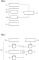
Fig. 3 shows a general flowchart for embodiments of the current invention. In step S1, multiple associated magnetic resonance data sets of different contrast are acquired using the same acquisition technique during an examination. Here, the same measurement sequence is used for all magnetic resonance data sets, however, the excitation is modified such that the noise characteristics of all magnetic resonance data sets are comparable, but the signal strength varies. For example, the acquisition technique can be diffusion weighted imaging (DWI), where a b=0 or low b, for example b=50, data set may be acquired with no or weak diffusion gradients applied. Furthermore, one or more b>0 data sets may be acquired using diffusion gradients. Monopolar or bipolar schemes may be used. - In a step S2, magnetic resonance images are reconstructed for each magnetic resonance data set, that is, each contrast. Here, several reconstruction steps S2a may be employed, however, reconstruction in step S2 at least comprises a denoising step S2b, in particular as the last step. However, it is understood that the denoising step S2b may be combined with one or more other reconstruction steps S2a, that is, denoising may be performed combined with another image processing operation. Alternatively, a dedicated denoising algorithm (denoising module) may be used.
- In the method described here, different denoising strengths are applied to different contrasts to optimize image quality regarding denoising, in particular to prevent too strong or too weak denoising. Therefore, in a step S3, a denoising strength measure is determined for each of the contrasts. While in some applications, at least one of the at least one noise strength measure may already be given by an acquisition parameter of the respective magnetic resonance data set, additionally or alternatively, at least one of the at least one noise strength measure may also be determined from the magnetic resonance data, in particular also from intermediate results of reconstruction steps S2a, for example a preliminary image transformed into image space. For example, a signal strength, a signal-to-noise ratio, and/or a noise strength may be determined by such an evaluation. In the case of diffusion weighted imaging, the b-value can be employed as or as a basis for determination of the at least one noise strength measure. In this concrete example, lower b-values lead to a lower denoising strength, since higher SNR is expected.
- As can be seen in
fig. 3 , the determined at least one noise strength measure is provided to the denoising step S2b to choose a suitable denoising strength for each contrast. - In a step S4, the magnetic resonance images determined in step S2 are output. Here, in some concrete embodiments, a user interaction option may be provided in the user interface for displaying the magnetic resonance images, allowing a user to modify determined noise strength values or denoising strength derived therefrom, for example by a slider, wherein, preferably in real time, the display of the magnetic resonance images may be updated according to the modification by at least partially re-executing the denoising step S2b. In particular, intermediate results used in denoising step S2b may be stored until user interaction indicating finality of the results is received.
- In the following, concrete embodiments regarding the denoising step S2b will be discussed with respect to
figs 4 to 6 . In the first embodiment offig. 4 , the denoising step S2b is the last step of the reconstruction in step S2. The previous reconstruction steps S2a yield afirst image result 33. Adedicated denoising algorithm 34, which may or may not comprise a trained function, is applied to thefirst image result 33 to determine a second,denoised image result 35. Thedenoising algorithm 34 uses a predefined denoising strength, which preferably is the highest expected required denoising strength. - In a
combination sub-step 36 of denoising step S2b, thefirst image result 33 and thesecond image result 35 are weightedly combined to determine themagnetic resonance image 37 for the currently reconstructed contrast as a final result. Here, the at least onenoise strength measure 38 determined in step S3 is used to determine the weights incombination sub-step 36. - In particular, in this manner, denoising strengths between the predefined denoising strength of the
denoising algorithm 34 and zero can be chosen according to the requirements for the different contrasts. - In a second concrete embodiment according to
fig. 5 , the denoising step S2b involves the application of a trainedfunction 39, to which anintermediate result 40 of other, previous reconstruction steps S2a is input. As further input, the trainedfunction 39, which is preferably a convolutional neural network 22 (CNN), receives the at least onenoise strength measure 38 determined in step S3 as meta data. Here, the trainedfunction 39 may have been actively trained to use the at least one noise strength measure concatenated with theintermediate result 40 as input, adapting the denoising strength accordingly. Preferably, however, the trainedfunction 39 has at least one parameter modifiable according to the at least onenoise strength measure 38 to adapt the trainedfunction 39 to apply a denoising strength suitable for the currently evaluated contrast. Such approaches have, for example, been proposed regarding the style transfer technique. - A third approach and concrete embodiment is illustrated in
fig. 6 . Here, aset 41 of n trainedfunctions functions intermediate result 40 to denoise according to the denoising strength. In this embodiment, the at least onenoise strength measure 38 of step S3 is used to select one of the trainedfunctions functions - A fourth approach and concrete embodiment is illustrated in
fig. 7 . The denoising step S2b is, in this case, embedded into the application of a trainedfunction 39, which comprises a variational neural network to determinemagnetic resonance images 37 from k-space magnetic resonance data sets. In this variational neural network, data consistency steps 50 andregularization steps 51 are repeatedly performed for a number of iterations of gradient descent steps 52, wherein the results of the respectivedata consistency step 50 andregularization step 51 are combined in astep 54 according to arelative scaling 53. Therelative scaling 54 is chosen dependent on thenoise strength measure 38 determined in step S3 resulting in different denoising strengths. In particular, higher relative scaling 54 leads to higher denoising strength. -
Fig. 8 schematically shows amagnetic resonance device 42 according to the current invention. As known from the art, themagnetic resonance device 42 comprises amain magnet unit 43 having a patient bore 44. Using a patient table (not shown), a patient can be introduced into the patient bore to measure magnetic resonance signals of the patient. To perform magnetic resonance examinations, themagnetic resonance device 42 comprises respective components which are not shown for simplicity, for example the main magnet, a gradient coil arrangement and a high frequency coil arrangement. - Operation of the
magnetic resonance device 42 is controlled by acontrol device 45, which, although indicated atmain magnet unit 43 infig. 7 , may of course be distributed, in particular comprise components outside a shielded room in which themain magnet unit 43 is located. -
Fig. 9 shows a functional structure of thecontrol device 45. Thecontrol device 45, as principally known, comprises anacquisition unit 46 controlling the acquisition of magnetic resonance data using the respective components. In particular, the acquisition unit is configured to acquire magnetic resonance data sets of different contrast using the acquisition technique according to step S1. Thecontrol device 35 further comprises areconstruction unit 47 configured to perform the reconstruction according to step S2 and adetermination unit 48 configured to determine the noise strength measure according to step S3. The resulting magnetic resonance images, wherein different denoising strengths were applied for different contrasts, may be output viaoutput interface 49 according to step S4. - Although the present invention has been described in detail with reference to the preferred embodiment, the present invention is not limited by the disclosed examples from which the skilled person is able to derive other variations without departing from the scope of the invention.
Claims (15)
- Computer-implemented method for determining magnetic resonance images (37) showing different contrasts in an examination, wherein magnetic resonance data for all magnetic resonance images (37) are acquired using the same acquisition technique and the magnetic resonance images (37) are reconstructed from their magnetic resonance data sets using at least one reconstruction algorithm, wherein reconstruction comprises at least one denoising step (S2b),
characterized in that- after acquisition of the magnetic resonance data, at least one noise strength measure (38) is determined for the magnetic resonance data sets for each contrast, and- denoising strengths for the denoising step (S2b) are chosen individually for each contrast depending on the respective at least one noise strength measure (38). - Method according to claim 1, characterized in that the magnetic resonance data sets of the different contrasts are acquired using the same measurement sequence and the same field of view, but with a respectively modified excitation sequence leading to different signal strengths for different contrasts.
- Method according to claim 1 or 2, characterized in that the acquisition technique is diffusion weighted imaging, wherein the different contrasts relate to different b values.
- Method according to one of the preceding claims, characterized in that a signal strength and/or a signal-to-noise ratio are determined as and/or to determine at least one of the at least one noise strength measure (38).
- Method according to one of the preceding claims, characterized in that the denoising step (S2b) is performed separately from other reconstruction steps (S2a) and uses a denoising algorithm (34), in particular as a last step during reconstruction.
- Method according to claim 5, characterized in that a first image result (33) for each contrast is obtained from reconstruction steps (S2a) applied before the denoising step (S2b), wherein in the denoising step (S2b):- the denoising algorithm (34) having a predefined, in particular maximum, denoising strength is applied to the first image result (33) to determine a second image result (35), and- the first image result (33) and the second image result (35) are weightedly combined to determine the magnetic resonance image (37), wherein the weights are chosen dependent on the at least one noise strength measure (38) for the respective contrast.
- Method according to one of the preceding claims, characterized in that the denoising step (S2b) involves the application of a trained function (39, 39a, 39b, 39c), in particular a convolutional neural network (22).
- Method according to claim 7, characterized in that the at least one noise strength measure (38) and/or a value derived therefrom are supplied as input data, in particular as meta data, to the trained function (39).
- Method according to claim 8, characterized in that the noise strength measure (38) is determined spatially resolved and provided to the trained function (39) as a noise level map.
- Method according to any of claims 7 to 9, characterized in that multiple trained functions (39, 39a, 39b, 39c) trained for multiple denoising strengths and/or denoising strength intervals are provided, wherein, for each contrast, the trained function (39a, 39b, 39c) to be applied is chosen depending on the at least one noise strength measure (38).
- Method according to any of the claims 7 to 10, characterized in that the trained function (39, 39a, 39b, 39c) comprises a variational neural network used to reconstruct magnetic resonance images (37) from k-space magnetic resonance data sets, wherein a data consistency step (50) and a regularization step (51) are repeatedly performed to obtain denoised magnetic resonance images (37) and a denoising strength for each contrast is chosen by adapting the relative scaling (53) between the data consistency step (50) and the regularization step (51) depending on the at least one noise strength measure (38).
- Method according to one of the preceding claims, characterized in that the magnetic resonance images (37) are displayed to the user, wherein upon user interaction the noise strength measure (38) for at least one contrast is updated based on user input and at least the denoising step (S2b) for this contrast is repeated based on the updated noise strength measure (38).
- Magnetic resonance device (42), comprising a control device (45) configured to perform a method according to one of the preceding claims.
- Computer program, which performs the steps of a method according to any of the claims 1 to 12 if the computer program is executed on a control device (45) of a magnetic resonance device (43).
- Electronically readable storage medium, on which a computer program according to claim 14 is stored.
Priority Applications (2)
| Application Number | Priority Date | Filing Date | Title |
|---|---|---|---|
| EP22155650.9A EP4224195A1 (en) | 2022-02-08 | 2022-02-08 | Computer-implemented method for denoising mr images of different contrasts acquired using the same acquisition technique |
| US18/107,124 US20230251338A1 (en) | 2022-02-08 | 2023-02-08 | Computer-Implemented Method for Determining Magnetic Resonance Images Showing Different Contrasts, Magnetic Resonance Device, Computer Program and Electronically Readable Storage Medium |
Applications Claiming Priority (1)
| Application Number | Priority Date | Filing Date | Title |
|---|---|---|---|
| EP22155650.9A EP4224195A1 (en) | 2022-02-08 | 2022-02-08 | Computer-implemented method for denoising mr images of different contrasts acquired using the same acquisition technique |
Publications (1)
| Publication Number | Publication Date |
|---|---|
| EP4224195A1 true EP4224195A1 (en) | 2023-08-09 |
Family
ID=80445796
Family Applications (1)
| Application Number | Title | Priority Date | Filing Date |
|---|---|---|---|
| EP22155650.9A Pending EP4224195A1 (en) | 2022-02-08 | 2022-02-08 | Computer-implemented method for denoising mr images of different contrasts acquired using the same acquisition technique |
Country Status (2)
| Country | Link |
|---|---|
| US (1) | US20230251338A1 (en) |
| EP (1) | EP4224195A1 (en) |
-
2022
- 2022-02-08 EP EP22155650.9A patent/EP4224195A1/en active Pending
-
2023
- 2023-02-08 US US18/107,124 patent/US20230251338A1/en active Pending
Non-Patent Citations (11)
| Title |
|---|
| D. ULYANOV ET AL.: "Instance Normalization: The Missing Ingredient for Fast Stylization", ARXIV: 1607.08022, 2016 |
| E. PEREZ ET AL.: "FiLM: Visual Reasoning with a General Conditioning Layer", PROCEEDINGS OF THE AAAI CONFERENCE ON ARTIFICIAL INTELLIGENCE, vol. 32, no. 1, 2018, pages 3942 - 3951 |
| HEMANT KUMAR AGGARWAL ET AL: "MoDL: Model Based Deep Learning Architecture for Inverse Problems", ARXIV.ORG, CORNELL UNIVERSITY LIBRARY, 201 OLIN LIBRARY CORNELL UNIVERSITY ITHACA, NY 14853, 7 December 2017 (2017-12-07), XP081410975 * |
| JIAHAO HU ET AL: "Adaptive Multi-contrast MR Image Denoising based on a Residual U-Net using Noise Level Map", PROCEEDINGS OF THE 2021 ISMRM & SMRT ANNUAL MEETING & EXHIBITION, 15-20 MAY 2021, ISMRM, 2030 ADDISON STREET, 7TH FLOOR, BERKELEY, CA 94704 USA, vol. 29, 1243, 30 April 2021 (2021-04-30), XP040723262 * |
| K. HAMMERNIK ET AL.: "Learning a variational network for reconstruction of accelerated MRI data", MAGN RESON MED, vol. 79, 2017, pages 3055 - 71 |
| K. ZHANG: "FFDNet: Toward a Fast and Flexible Solution for CNN based Image Denoising", ARXIV:1710.04026, 2017 |
| MERRY P MANI ET AL: "Model-Based Deep Learning for Reconstruction of Joint k-q Under-sampled High Resolution Diffusion MRI", ARXIV.ORG, CORNELL UNIVERSITY LIBRARY, 201 OLIN LIBRARY CORNELL UNIVERSITY ITHACA, NY 14853, 23 January 2020 (2020-01-23), XP081584206 * |
| P. KELLMAN ET AL.: "Image reconstruction in SNR units: a general method for SNR measurement", MAGN RESON MED, vol. 54, 2005, pages 1439 - 47, XP002744493, DOI: 10.1002/mrm.20713 |
| P. M. ROBSON ET AL.: "Comprehensive Quantification of Signal-to-Noise Ratio and g-Factor for Image-Based and k-Space-Based Parallel Imaging Reconstructions", MAGN RESON MED, vol. 60, 2008, pages 895 - 907, XP055159093, DOI: 10.1002/mrm.21728 |
| SIEMENS AG DR MARCEL DOMINIK NICKEL DE-ERLANGEN ET AL: "Machine-Learning-Based Denoising of Complex Magnetic-Resonance-Imaging Data Using a Guidance Map", PRIOR ART PUBLISHING GMBH, PRIOR ART PUBLISHING GMBH, MANFRED-VON-RICHTHOFEN-STR. 9, 12101 BERLIN GERMANY, vol. www.priorartregister.com, 20 October 2021 (2021-10-20), pages 1 - 2, XP007024392 * |
| X. HUANGS. BELONGIE: "Arbitrary Style Transfer in Real-time with Adaptive Instance Normalization", PROCEEDINGS OF THE IEEE INTERNATIONAL CONFERENCE ON COMPUTER VISION, 2017, pages 1501 - 1510 |
Also Published As
| Publication number | Publication date |
|---|---|
| US20230251338A1 (en) | 2023-08-10 |
Similar Documents
| Publication | Publication Date | Title |
|---|---|---|
| CN111656392B (en) | System and method for synthesizing magnetic resonance images | |
| CN104323775B (en) | Magnetic resonance imaging apparatus, image processing apparatus, and image processing method | |
| Pierre et al. | Multiscale reconstruction for MR fingerprinting | |
| US11169235B2 (en) | Method and apparatus for processing magnetic resonance data | |
| US10379188B2 (en) | MRI using spatially adaptive regularization for image reconstruction | |
| Forman et al. | Reduction of respiratory motion artifacts for free‐breathing whole‐heart coronary MRA by weighted iterative reconstruction | |
| JPWO2007043462A1 (en) | Brain function data analysis method, brain function analysis apparatus, and brain function analysis program | |
| US11965946B2 (en) | Machine learning based processing of magnetic resonance data, including an uncertainty quantification | |
| US10736538B2 (en) | Method and computer differentiating correlation patterns in functional magnetic resonance imaging | |
| US11125845B2 (en) | Apparatus and method for deep learning to mitigate artifacts arising in simultaneous multi slice (SMS) magnetic resonance imaging (MRI) | |
| EP4224195A1 (en) | Computer-implemented method for denoising mr images of different contrasts acquired using the same acquisition technique | |
| US10825169B2 (en) | Method and apparatus for functional magnetic resonance imaging | |
| St-Jean et al. | Automatic, fast and robust characterization of noise distributions for diffusion MRI | |
| Pham et al. | A generalized EM algorithm for robust segmentation of magnetic resonance images | |
| González-Jaime et al. | Spatially-variant noise filtering in magnetic resonance imaging: A consensus-based approach | |
| US11662414B2 (en) | Trained image processing for diffusion weighted imaging and/or turbo spin echo sequences with focus on body applications | |
| US20240077561A1 (en) | Noise adaptive data consistency in deep learning image reconstruction via norm ball projection | |
| EP4095539A1 (en) | Task-specific training of a neural network algorithm for magnetic resonance imaging reconstruction and object detection | |
| US20230140523A1 (en) | Method for generating magnetic resonance image and magnetic resonance imaging system | |
| Walheim | Accelerating High-Dimensional Magnetic Resonance Flow Imaging | |
| Netreba et al. | Object Spin Characteristics Restoration for Combined Tissue Areas in MRI | |
| Demirel et al. | High-Quality 0.5 mm Isotropic fMRI: Random Matrix Theory Meets Physics-Driven Deep Learning | |
| Kaimal | Deep Sequential Compressed Sensing for Dynamic MRI | |
| Li et al. | Radial Undersampled MRI Reconstruction Using Deep Learning with Mutual Constraints between Real and Imaginary Components of K-Space | |
| Yang et al. | Unsupervised Adaptive Implicit Neural Representation Learning for Scan-Specific MRI Reconstruction |
Legal Events
| Date | Code | Title | Description |
|---|---|---|---|
| PUAI | Public reference made under article 153(3) epc to a published international application that has entered the european phase |
Free format text: ORIGINAL CODE: 0009012 |
|
| STAA | Information on the status of an ep patent application or granted ep patent |
Free format text: STATUS: THE APPLICATION HAS BEEN PUBLISHED |
|
| AK | Designated contracting states |
Kind code of ref document: A1 Designated state(s): AL AT BE BG CH CY CZ DE DK EE ES FI FR GB GR HR HU IE IS IT LI LT LU LV MC MK MT NL NO PL PT RO RS SE SI SK SM TR |
|
| STAA | Information on the status of an ep patent application or granted ep patent |
Free format text: STATUS: REQUEST FOR EXAMINATION WAS MADE |
|
| RAP1 | Party data changed (applicant data changed or rights of an application transferred) |
Owner name: SIEMENS HEALTHINEERS AG |
|
| 17P | Request for examination filed |
Effective date: 20240205 |
|
| RBV | Designated contracting states (corrected) |
Designated state(s): AL AT BE BG CH CY CZ DE DK EE ES FI FR GB GR HR HU IE IS IT LI LT LU LV MC MK MT NL NO PL PT RO RS SE SI SK SM TR |