EP4224124A1 - Water level measurement system - Google Patents
Water level measurement system Download PDFInfo
- Publication number
- EP4224124A1 EP4224124A1 EP21875981.9A EP21875981A EP4224124A1 EP 4224124 A1 EP4224124 A1 EP 4224124A1 EP 21875981 A EP21875981 A EP 21875981A EP 4224124 A1 EP4224124 A1 EP 4224124A1
- Authority
- EP
- European Patent Office
- Prior art keywords
- water level
- measurement system
- ultrasonic
- level measurement
- water
- Prior art date
- Legal status (The legal status is an assumption and is not a legal conclusion. Google has not performed a legal analysis and makes no representation as to the accuracy of the status listed.)
- Pending
Links
Images


Classifications
-
- G—PHYSICS
- G01—MEASURING; TESTING
- G01F—MEASURING VOLUME, VOLUME FLOW, MASS FLOW OR LIQUID LEVEL; METERING BY VOLUME
- G01F23/00—Indicating or measuring liquid level or level of fluent solid material, e.g. indicating in terms of volume or indicating by means of an alarm
- G01F23/22—Indicating or measuring liquid level or level of fluent solid material, e.g. indicating in terms of volume or indicating by means of an alarm by measuring physical variables, other than linear dimensions, pressure or weight, dependent on the level to be measured, e.g. by difference of heat transfer of steam or water
- G01F23/28—Indicating or measuring liquid level or level of fluent solid material, e.g. indicating in terms of volume or indicating by means of an alarm by measuring physical variables, other than linear dimensions, pressure or weight, dependent on the level to be measured, e.g. by difference of heat transfer of steam or water by measuring the variations of parameters of electromagnetic or acoustic waves applied directly to the liquid or fluent solid material
- G01F23/296—Acoustic waves
- G01F23/2961—Acoustic waves for discrete levels
-
- G—PHYSICS
- G21—NUCLEAR PHYSICS; NUCLEAR ENGINEERING
- G21C—NUCLEAR REACTORS
- G21C19/00—Arrangements for treating, for handling, or for facilitating the handling of, fuel or other materials which are used within the reactor, e.g. within its pressure vessel
- G21C19/02—Details of handling arrangements
- G21C19/06—Magazines for holding fuel elements or control elements
- G21C19/07—Storage racks; Storage pools
-
- Y—GENERAL TAGGING OF NEW TECHNOLOGICAL DEVELOPMENTS; GENERAL TAGGING OF CROSS-SECTIONAL TECHNOLOGIES SPANNING OVER SEVERAL SECTIONS OF THE IPC; TECHNICAL SUBJECTS COVERED BY FORMER USPC CROSS-REFERENCE ART COLLECTIONS [XRACs] AND DIGESTS
- Y02—TECHNOLOGIES OR APPLICATIONS FOR MITIGATION OR ADAPTATION AGAINST CLIMATE CHANGE
- Y02E—REDUCTION OF GREENHOUSE GAS [GHG] EMISSIONS, RELATED TO ENERGY GENERATION, TRANSMISSION OR DISTRIBUTION
- Y02E30/00—Energy generation of nuclear origin
- Y02E30/30—Nuclear fission reactors
Definitions
- the present invention relates to a water level measurement system, and more particularly, to a water level measurement system using ultrasonic waves.
- the level of cooling water filled inside a nuclear fuel reloading tank or a nuclear fuel storage tank of a nuclear power plant is monitored, and a safety response system and procedure should be prepared accordingly. That is, in the nuclear fuel reloading tank or the nuclear fuel storage tank, the cooling process is performed for the decay heat, and the forced cooling by a pump is performed. At this time, in the case of the nuclear fuel storage tank, when the cooling function is lost or the forced circulation is not performed, the fuel storage storage tank boils and then the steam may be mixed. At this time, the water level must be monitored so that an alternative water source can be mobilized immediately, and the condition thereof must be monitored through continuous water level monitoring even after the alternative water source is fed into the water.
- a water level measurement method of a differential pressure type or a water level measurement method of an ultrasonic wave type is used to measure the water level.
- the water level measurement method of the ultrasonic wave measures the water level by calculating the time between ultrasonic waves emitted and ultrasonic waves reflected in a dense medium such as a liquid or by using an interference fringe of the ultrasonic waves.
- the water level measurement method of the ultrasonic wave is highly correlated with the presence of reflected waves reflected after the ultrasonic waves are transmitted through the dense medium.
- a thermal contact radar method In order to supplement these water level measurement methods, a thermal contact radar method, a thermal diffusion radar method, or a method of measuring the water level by imitating the shape of a radar are used, but in these methods, complex modules or equipment for analysis and interpretation are combined an equipment for analyzing radar-type data must be installed, so the price and cost of the equipment itself increases.
- the present embodiment relates to a water level measurement system capable of accurately measuring a water level even under abnormal conditions.
- a water level measurement system includes a support pipe installed in a water tank filled with a fluid to measure a water level and extending in a depth direction of the water tank, a support rod disposed on one side of the support pipe based on a central axis of the support pipe and extending in the depth direction of the water tank, a plurality of ultrasonic probes attached to the support rod and generating ultrasonic waves, and a water level calculator connected to the plurality of ultrasonic probes and calculating the water level of the water tank.
- the support rod may be in contact with an inner wall of the support pipe.
- the ultrasonic probe may be installed at a position facing an exposed inner wall of the support pipe.
- the plurality of ultrasonic probes may propagate the ultrasonic wave in a horizontal direction parallel to a surface of the fluid.
- the water level calculator may calculate the water level of the water tank by using a number of ultrasonic probes that have detected signals of reflected waves reflected from the support pipe among the plurality of ultrasonic probes.
- the water level in the water tank is calculated as (L/N) * S.
- the plurality of ultrasonic probes may be disposed in the depth direction of the water tank.
- the water level measurement system may further a fixing member fixing the ultrasonic probe to the support rod.
- the water tank may include a nuclear fuel reloading tank or a nuclear fuel storage tank of a nuclear power plant.
- the water level can be accurately measured even under abnormal conditions in which bubbles or steam are generated inside the water tank.
- the water level of the fluid filled in the water tank can be measured using an ultrasonic probe, which is a low-cost apparatus, the water level can be quickly measured at a low cost compared to a method using expensive radar-type equipment.
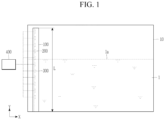
- FIG. 1 is a drawing schematically illustrating a state in which a water level measurement system according to an embodiment is installed in a water tank
- FIG. 2 is a partial perspective view of a water level measurement system according to an embodiment
- FIG. 3 is a plan view of a water level measurement according to an embodiment.
- the water level measurement system includes a support pipe 100, a support rod 200, a plurality of ultrasonic probes 300, a water level calculator 400, and a plurality of fixing members 500.
- the support pipe 100 may be installed in the water tank 10 filled with the fluid 1 to measure the water level.
- the support pipe 100 may extend long in the depth direction Y of the water tank 10 and may have a predetermined length L.
- the support pipe 100 may have a lower portion disposed below a water surface 1a of the fluid 1 filled in the water tank 10 and an upper portion disposed above the water surface 1a of the fluid 1.
- the fluid 1 may be filled in the inner space O of the support pipe 100.
- the support pipe 100 may be made of a material such as metal.
- the water tank 10 may include a nuclear fuel reloading tank or a nuclear fuel storage tank of a nuclear power plant. Therefore, the present invention can monitor the water level of the cooling water filled inside the water tank 10 of the nuclear power plant. However, the present invention is not necessarily limited thereto and can be applied to various water tanks.
- the support rod 200 may be disposed in the inner space O of the support pipe 100.
- the support rod 200 may be disposed on one side of the support pipe 100 based on the central axis C of the support pipe 100 and may extend in the depth direction Y.
- the length L of the support rod 200 may be the same as the length L of the support pipe 100. However, it is not necessarily limited thereto, and the length L of the support rod 200 may be different from the length L of the support pipe 100 according to the embodiment.
- the support rod 200 may be disposed on one side of the support pipe 100 in contact with the inner wall of the support pipe 100. Therefore, the fluid 1 may be disposed in a narrow inner space O between the inner wall of the support pipe 100 and the support rod 200. Therefore, even under abnormal conditions in which boiling occurs in the water tank 10 and bubbles or steam are generated, bubbles or steam hard to exist in the fluid 1 disposed in the narrow space between the inner wall of the support pipe 100 and the support rod 200.
- a plurality of ultrasonic probes 300 may be attached to a circumferential surface of the support rod 200 to generate ultrasonic waves L1 and L2 and may detect a reflected wave R. Also, the plurality of ultrasonic probes 300 may propagate the ultrasonic waves in a horizontal direction X parallel to the surface 1a of the fluid 1. Therefore, ultrasonic waves generated by the plurality of ultrasonic probes 300 may propagate to the inner wall of the support pipe 100. At this time, since it is difficult for bubbles or steam to exist on the path of ultrasonic waves, the water level may be accurately measured.
- the plurality of ultrasonic probes 300 may be spaced apart at predetermined gap in the depth direction Y of the water tank 10.
- the ultrasonic probe 300 may be installed on the circumferential surface of the support rod 200 at a position facing the exposed inner wall of the support pipe 100. Therefore, the ultrasonic waves can be generated in one direction from the support rod 200.
- the side wall to which the plurality of ultrasonic probes 300 are attached among the side walls of the filled support rod 200 may not directly contact the inner wall of the support pipe 100 facing the same each other and may have a structure separated from each other. Therefore, the vibration of ultrasonic waves generated from the plurality of ultrasonic probes 300 attached to the support rod 200 may not directly affect the support pipe 100 spaced apart from the support rod 200, so that the interference of ultrasonic waves is removed, thereby more accurately measuring the water level.
- the ultrasonic probe 300 is attached to the fixed support rod 200 filling the inside to transmit ultrasonic waves to the support pipe 100 that does not directly contact the ultrasonic probe 300, ultrasonic waves between the ultrasonic probe 300 do not interfere with each other, thereby generating interference signals or noise signals. Therefore, since complicated additional equipment such as an arithmetic processing device for processing the interference signals or noise signals is not required, and each ultrasonic probe 300 independently measures the water level, a simple structure is possible and manufacturing costs can be minimized.
- FIG. 4 is a partially enlarged view of a water level measurement system according to an embodiment, and is a drawing illustrating a state in which ultrasonic waves propagate above and below the water surface.
- the ultrasonic probe 300 since the ultrasonic wave L1 generated by the ultrasonic probe 300 disposed below the water surface 1a propagates inside the fluid 1, a reflected wave may be generated on the inner wall of the support pipe 100, and since the reflected wave R propagates to the ultrasonic probe 300 again, the ultrasonic probe 300 can detect the reflected wave.
- the ultrasonic wave L2 generated by the ultrasonic probe 300 disposed above the water surface 1a does not propagates inside the fluid 1, it is dissipated or scattered on the inner wall of the support pipe 100, so that the ultrasonic probe 300 cannot detect the reflected wave R.
- the water level calculator 400 may be connected to the plurality of ultrasonic probes 300 to calculate the water level of the water tank 10.
- the water level calculator 400 can calculate the water level of the water tank 10 by summing the number of ultrasonic probes 300 that detect the signal of the reflected wave R reflected from the support pipe 100 among the plurality of ultrasonic probes 300.
- each ultrasonic probe 300 may serve as a channel for measuring the water level. That is, when the water level is to be measured with 100 channels in the water tank 10 filled with the fluid 1 having a water level of 6 m, 100 ultrasonic probes 300 may be installed on the support rod 200 with the length of 6 m, and one ultrasonic probe 300 may be disposed every 6 cm.
- 150 ultrasonic probes 300 may be installed on the support rod 200 with the length of 4 m, and one ultrasonic probe 300 may be disposed every 2.67 cm.
- the water level of the water tank 10 can be more accurately measured.
- the ultrasonic waves propagate between the support rod 200 and the inner wall of the support pipe 100, which is a space where no bubbles or steam are generated, so that the water level of the fluid 1 filled inside the water tank 10 can be more accurately measured.
- the water level of the fluid 1 filled in the water tank 10 can be measured using the ultrasonic probe 300, which is a low-cost apparatus, the water level can be quickly measured at a low cost compared to a method using expensive radar-type equipment.
- the plurality of fixing members 500 may fix the plurality of ultrasonic probes 300 to the support rod 200.
- the fixing member 500 may include a first fixing member 510 and a second fixing member 520 respectively installed in contact with the upper and lower surfaces of the ultrasonic probe 300. Since shaking of the ultrasonic probe 300 can be prevented by using the first fixing member 510 and the second fixing member 520, the water level can be more accurately measured by the ultrasonic probe 300.
Landscapes
- Physics & Mathematics (AREA)
- General Physics & Mathematics (AREA)
- Acoustics & Sound (AREA)
- Electromagnetism (AREA)
- Thermal Sciences (AREA)
- Fluid Mechanics (AREA)
- Engineering & Computer Science (AREA)
- Plasma & Fusion (AREA)
- General Engineering & Computer Science (AREA)
- High Energy & Nuclear Physics (AREA)
- Measurement Of Levels Of Liquids Or Fluent Solid Materials (AREA)
- Monitoring And Testing Of Nuclear Reactors (AREA)
Abstract
Description
- The present invention relates to a water level measurement system, and more particularly, to a water level measurement system using ultrasonic waves.
- In general, the level of cooling water filled inside a nuclear fuel reloading tank or a nuclear fuel storage tank of a nuclear power plant is monitored, and a safety response system and procedure should be prepared accordingly. That is, in the nuclear fuel reloading tank or the nuclear fuel storage tank, the cooling process is performed for the decay heat, and the forced cooling by a pump is performed. At this time, in the case of the nuclear fuel storage tank, when the cooling function is lost or the forced circulation is not performed, the fuel storage storage tank boils and then the steam may be mixed. At this time, the water level must be monitored so that an alternative water source can be mobilized immediately, and the condition thereof must be monitored through continuous water level monitoring even after the alternative water source is fed into the water.
- In general, a water level measurement method of a differential pressure type or a water level measurement method of an ultrasonic wave type is used to measure the water level. In the water level measurement method of the differential pressure type, when bubbles or steam are generated inside the water tank, it is difficult to measure the water level by differential pressure due to rapid fluctuations of the fluid. The water level measurement method of the ultrasonic wave measures the water level by calculating the time between ultrasonic waves emitted and ultrasonic waves reflected in a dense medium such as a liquid or by using an interference fringe of the ultrasonic waves. The water level measurement method of the ultrasonic wave is highly correlated with the presence of reflected waves reflected after the ultrasonic waves are transmitted through the dense medium. When conditions are not normal, that is, when the cooling function of the nuclear fuel reloading tank or the nuclear fuel storage tank is lost, the boiling occurs in the cooling water, and bubbles or steam are rapidly generated, it is difficult to calculate a standardized reflected wave because the reflected wave is extinguished or lost. Therefore, it is difficult to accurately measure the reflected wave, and there is a limit to measuring the water level. In particular, when the bubbles are generated, it is difficult to accurately measure the water level because the waveform of the ultrasonic wave is uneven.
- In order to supplement these water level measurement methods, a thermal contact radar method, a thermal diffusion radar method, or a method of measuring the water level by imitating the shape of a radar are used, but in these methods, complex modules or equipment for analysis and interpretation are combined an equipment for analyzing radar-type data must be installed, so the price and cost of the equipment itself increases.
- The present embodiment relates to a water level measurement system capable of accurately measuring a water level even under abnormal conditions.
- A water level measurement system according to an embodiment includes a support pipe installed in a water tank filled with a fluid to measure a water level and extending in a depth direction of the water tank, a support rod disposed on one side of the support pipe based on a central axis of the support pipe and extending in the depth direction of the water tank, a plurality of ultrasonic probes attached to the support rod and generating ultrasonic waves, and a water level calculator connected to the plurality of ultrasonic probes and calculating the water level of the water tank.
- The support rod may be in contact with an inner wall of the support pipe.
- The ultrasonic probe may be installed at a position facing an exposed inner wall of the support pipe.
- The plurality of ultrasonic probes may propagate the ultrasonic wave in a horizontal direction parallel to a surface of the fluid.
- The water level calculator may calculate the water level of the water tank by using a number of ultrasonic probes that have detected signals of reflected waves reflected from the support pipe among the plurality of ultrasonic probes.
- When the number of the plurality of ultrasonic probes is N, a length of the support rod is L, and the number of ultrasonic probes detecting the signal of the reflected wave is S, the water level in the water tank is calculated as (L/N) * S.
- The plurality of ultrasonic probes may be disposed in the depth direction of the water tank.
- The water level measurement system may further a fixing member fixing the ultrasonic probe to the support rod.
- The water tank may include a nuclear fuel reloading tank or a nuclear fuel storage tank of a nuclear power plant.
- According to an embodiment, since ultrasonic waves propagate a space between the support rod and the inner wall of the support pipe, where bubbles or steam are not generated, the water level can be accurately measured even under abnormal conditions in which bubbles or steam are generated inside the water tank.
- In addition, since the water level of the fluid filled in the water tank can be measured using an ultrasonic probe, which is a low-cost apparatus, the water level can be quickly measured at a low cost compared to a method using expensive radar-type equipment.
-
-
FIG. 1 is a drawing schematically illustrating a state in which a water level measurement system according to an embodiment is installed in a water tank. -
FIG. 2 is a partial perspective view of a water level measurement system according to an embodiment. -
FIG. 3 is a plan view of a water level measurement system according to one embodiment. -
FIG. 4 is a partially enlarged view of a water level measurement system according to an embodiment, and is a drawing illustrating a state in which ultrasonic waves propagate above and below the water surface. - Hereinafter, in order to aid understanding of the present invention, various embodiments of the present invention will be described in detail so that those skilled in the art can easily carry out the present invention with reference to the accompanying drawings. The present disclosure may be embodied in many different forms and is not limited to the embodiments described herein.
- In order to clearly illustrate the present disclosure, parts that are not related to the description are omitted, and the same or similar constituent elements are given the same reference numerals throughout the specification.
- In addition, since the size and thickness of each configuration shown in the drawing are arbitrarily shown for better understanding and ease of description, the present disclosure is not necessarily limited to the illustrated one.
-
FIG. 1 is a drawing schematically illustrating a state in which a water level measurement system according to an embodiment is installed in a water tank,FIG. 2 is a partial perspective view of a water level measurement system according to an embodiment, andFIG. 3 is a plan view of a water level measurement according to an embodiment. - As shown in
FIG. 1 , the water level measurement system according to an embodiment includes asupport pipe 100, asupport rod 200, a plurality ofultrasonic probes 300, awater level calculator 400, and a plurality offixing members 500. - The
support pipe 100 may be installed in thewater tank 10 filled with thefluid 1 to measure the water level. Thesupport pipe 100 may extend long in the depth direction Y of thewater tank 10 and may have a predetermined length L. Thesupport pipe 100 may have a lower portion disposed below a water surface 1a of thefluid 1 filled in thewater tank 10 and an upper portion disposed above the water surface 1a of thefluid 1. Thus, thefluid 1 may be filled in the inner space O of thesupport pipe 100. Thesupport pipe 100 may be made of a material such as metal. Thewater tank 10 may include a nuclear fuel reloading tank or a nuclear fuel storage tank of a nuclear power plant. Therefore, the present invention can monitor the water level of the cooling water filled inside thewater tank 10 of the nuclear power plant. However, the present invention is not necessarily limited thereto and can be applied to various water tanks. - The
support rod 200 may be disposed in the inner space O of thesupport pipe 100. Thesupport rod 200 may be disposed on one side of thesupport pipe 100 based on the central axis C of thesupport pipe 100 and may extend in the depth direction Y. The length L of thesupport rod 200 may be the same as the length L of thesupport pipe 100. However, it is not necessarily limited thereto, and the length L of thesupport rod 200 may be different from the length L of thesupport pipe 100 according to the embodiment. Thesupport rod 200 may be disposed on one side of thesupport pipe 100 in contact with the inner wall of thesupport pipe 100. Therefore, thefluid 1 may be disposed in a narrow inner space O between the inner wall of thesupport pipe 100 and thesupport rod 200. Therefore, even under abnormal conditions in which boiling occurs in thewater tank 10 and bubbles or steam are generated, bubbles or steam hard to exist in thefluid 1 disposed in the narrow space between the inner wall of thesupport pipe 100 and thesupport rod 200. - A plurality of
ultrasonic probes 300 may be attached to a circumferential surface of thesupport rod 200 to generate ultrasonic waves L1 and L2 and may detect a reflected wave R. Also, the plurality ofultrasonic probes 300 may propagate the ultrasonic waves in a horizontal direction X parallel to the surface 1a of thefluid 1. Therefore, ultrasonic waves generated by the plurality ofultrasonic probes 300 may propagate to the inner wall of thesupport pipe 100. At this time, since it is difficult for bubbles or steam to exist on the path of ultrasonic waves, the water level may be accurately measured. - The plurality of
ultrasonic probes 300 may be spaced apart at predetermined gap in the depth direction Y of thewater tank 10. - The
ultrasonic probe 300 may be installed on the circumferential surface of thesupport rod 200 at a position facing the exposed inner wall of thesupport pipe 100. Therefore, the ultrasonic waves can be generated in one direction from thesupport rod 200. - At this time, the side wall to which the plurality of
ultrasonic probes 300 are attached among the side walls of the filledsupport rod 200 may not directly contact the inner wall of thesupport pipe 100 facing the same each other and may have a structure separated from each other. Therefore, the vibration of ultrasonic waves generated from the plurality ofultrasonic probes 300 attached to thesupport rod 200 may not directly affect thesupport pipe 100 spaced apart from thesupport rod 200, so that the interference of ultrasonic waves is removed, thereby more accurately measuring the water level. - That is, since the
ultrasonic probe 300 is attached to thefixed support rod 200 filling the inside to transmit ultrasonic waves to thesupport pipe 100 that does not directly contact theultrasonic probe 300, ultrasonic waves between theultrasonic probe 300 do not interfere with each other, thereby generating interference signals or noise signals. Therefore, since complicated additional equipment such as an arithmetic processing device for processing the interference signals or noise signals is not required, and eachultrasonic probe 300 independently measures the water level, a simple structure is possible and manufacturing costs can be minimized. -
FIG. 4 is a partially enlarged view of a water level measurement system according to an embodiment, and is a drawing illustrating a state in which ultrasonic waves propagate above and below the water surface. - As shown in
FIG. 4 , since the ultrasonic wave L1 generated by theultrasonic probe 300 disposed below the water surface 1a propagates inside thefluid 1, a reflected wave may be generated on the inner wall of thesupport pipe 100, and since the reflected wave R propagates to theultrasonic probe 300 again, theultrasonic probe 300 can detect the reflected wave. - In addition, since the ultrasonic wave L2 generated by the
ultrasonic probe 300 disposed above the water surface 1a does not propagates inside thefluid 1, it is dissipated or scattered on the inner wall of thesupport pipe 100, so that theultrasonic probe 300 cannot detect the reflected wave R. - The
water level calculator 400 may be connected to the plurality ofultrasonic probes 300 to calculate the water level of thewater tank 10. Thewater level calculator 400 can calculate the water level of thewater tank 10 by summing the number ofultrasonic probes 300 that detect the signal of the reflected wave R reflected from thesupport pipe 100 among the plurality ofultrasonic probes 300. - That is, when the number of the plurality of
ultrasonic probes 300 is N, the length of the support rod 200 (or support pipe 100) is L, and the number ofultrasonic probes 300 detecting the signal of the reflected wave R is S, the water level P of thewater tank 10 may be expressed byEquation 1 below.
- At this time, each
ultrasonic probe 300 may serve as a channel for measuring the water level. That is, when the water level is to be measured with 100 channels in thewater tank 10 filled with thefluid 1 having a water level of 6 m, 100ultrasonic probes 300 may be installed on thesupport rod 200 with the length of 6 m, and oneultrasonic probe 300 may be disposed every 6 cm. - In addition, when the water level is to be measured with 150 channels in the
water tank 10 having a water level of 4 m, 150ultrasonic probes 300 may be installed on thesupport rod 200 with the length of 4 m, and oneultrasonic probe 300 may be disposed every 2.67 cm. At this time, when the number of channels through which the signal of the reflected wave R is detected is 123 channels, the number S of theultrasonic probes 300 detecting the signal of the reflected wave R becomes 123. Therefore, since the total number N ofultrasonic probes 300 is 150 and the length L of thesupport rod 200 is 400 cm, the water level P of thewater tank 10 may be calculated as (400 cm/150) * 123 = 328.41 cm. - In addition, by increasing the number of channels, that is, the number of the
ultrasonic probes 300, the water level of thewater tank 10 can be more accurately measured. - As described above, in the water level measurement system according to an embodiment of the present invention, the ultrasonic waves propagate between the
support rod 200 and the inner wall of thesupport pipe 100, which is a space where no bubbles or steam are generated, so that the water level of thefluid 1 filled inside thewater tank 10 can be more accurately measured. - In addition, since the water level of the
fluid 1 filled in thewater tank 10 can be measured using theultrasonic probe 300, which is a low-cost apparatus, the water level can be quickly measured at a low cost compared to a method using expensive radar-type equipment. - The plurality of fixing
members 500 may fix the plurality ofultrasonic probes 300 to thesupport rod 200. The fixingmember 500 may include a first fixingmember 510 and a second fixing member 520 respectively installed in contact with the upper and lower surfaces of theultrasonic probe 300. Since shaking of theultrasonic probe 300 can be prevented by using the first fixingmember 510 and the second fixing member 520, the water level can be more accurately measured by theultrasonic probe 300. - Although the present disclosure has been described through preferred embodiments as described above, the present invention is not limited thereto and various modifications and variations are possible without departing from the scope of the claims described below. Those in the field will easily understand.
Claims (9)
- A water level measurement system comprising:a support pipe installed in a water tank filled with a fluid to measure a water level and extending in a depth direction of the water tank;a support rod disposed on one side of the support pipe based on a central axis of the support pipe and extending in the depth direction of the water tank;a plurality of ultrasonic probes attached to the support rod and generating ultrasonic waves, anda water level calculator connected to the plurality of ultrasonic probes and calculating the water level of the water tank
- The water level measurement system of claim 1, wherein
the support rod is in contact with an inner wall of the support pipe. - The water level measurement system of claim 1, wherein
the ultrasonic probe is installed at a position facing an exposed inner wall of the support pipe. - The water level measurement system of claim 3, wherein
the plurality of ultrasonic probes propagate the ultrasonic waves in a horizontal direction parallel to a surface of the fluid. - The water level measurement system of 1, wherein
the water level calculator calculates the water level of the water tank by using a number of ultrasonic probes that detect signals of reflected waves reflected from the support pipe among the plurality of ultrasonic probes. - The water level measurement system of 5, wherein
when the number of the plurality of ultrasonic probes is N, a length of the support rod is L, and the number of ultrasonic probes detecting the signal of the reflected wave is S, the water level of the water tank is calculated as (L / N) * S. - The water level measurement system of 1, wherein
the plurality of ultrasonic probes are disposed in the depth direction of the water tank. - The water level measurement system of 1, further comprising
a fixing member fixing the ultrasonic probe to the support rod. - The water level measurement system of 1, wherein
the water tank includes a nuclear fuel reloading tank or a nuclear fuel storage tank of a nuclear power plant.
Applications Claiming Priority (2)
| Application Number | Priority Date | Filing Date | Title |
|---|---|---|---|
| KR1020200127325A KR102353351B1 (en) | 2020-09-29 | 2020-09-29 | Water level measurement system |
| PCT/KR2021/013163 WO2022071706A1 (en) | 2020-09-29 | 2021-09-27 | Water level measurement system |
Publications (2)
| Publication Number | Publication Date |
|---|---|
| EP4224124A1 true EP4224124A1 (en) | 2023-08-09 |
| EP4224124A4 EP4224124A4 (en) | 2024-11-20 |
Family
ID=80051939
Family Applications (1)
| Application Number | Title | Priority Date | Filing Date |
|---|---|---|---|
| EP21875981.9A Pending EP4224124A4 (en) | 2020-09-29 | 2021-09-27 | Water level measurement system |
Country Status (6)
| Country | Link |
|---|---|
| US (1) | US20230366718A1 (en) |
| EP (1) | EP4224124A4 (en) |
| JP (1) | JP2023543311A (en) |
| KR (1) | KR102353351B1 (en) |
| CN (1) | CN116529564B (en) |
| WO (1) | WO2022071706A1 (en) |
Families Citing this family (1)
| Publication number | Priority date | Publication date | Assignee | Title |
|---|---|---|---|---|
| KR102944969B1 (en) * | 2024-11-06 | 2026-03-26 | 정혜린 | Water level and management of reservoirs for disaster prevention with AI function. Image management system and management method using it |
Family Cites Families (17)
| Publication number | Priority date | Publication date | Assignee | Title |
|---|---|---|---|---|
| JPS56130616A (en) * | 1980-03-19 | 1981-10-13 | Toshiba Corp | Ultrasonic liquid level indicator |
| JPS60148998A (en) * | 1984-01-17 | 1985-08-06 | 日立建機株式会社 | Apparatus for detecting distance between hole pit drilling machine and ground in hole pit |
| DE69217994T2 (en) * | 1991-07-25 | 1997-09-04 | Whitaker Corp | LIQUID LEVEL METER |
| GB9608752D0 (en) * | 1996-04-26 | 1996-07-03 | Amp Great Britain | Liquid sensor |
| GB0118320D0 (en) * | 2001-07-27 | 2001-09-19 | Ici Plc | Level measurement |
| US8061196B2 (en) * | 2008-12-01 | 2011-11-22 | Cosense, Inc. | Bottom up contact type ultrasonic continuous level sensor |
| JP5606703B2 (en) * | 2009-04-27 | 2014-10-15 | 株式会社東芝 | Liquid level measuring device |
| KR101227914B1 (en) * | 2010-04-20 | 2013-02-07 | 주식회사 하이드로소닉 | Ultrasonic flow measuring method for artificially open canal and apparatus thereof |
| KR101227910B1 (en) * | 2010-04-20 | 2013-01-30 | 주식회사 하이드로소닉 | Sonic wide range level measuring method and apparatus thereof |
| JP5774469B2 (en) * | 2011-12-28 | 2015-09-09 | 株式会社東芝 | Liquid level measuring device, method and program |
| KR101430690B1 (en) * | 2013-01-21 | 2014-08-18 | 동국대학교 경주캠퍼스 산학협력단 | A water level monitoring system for spent fuel pool at nuclear power plant |
| WO2014117213A1 (en) * | 2013-01-29 | 2014-08-07 | Binmartine Pty Ltd | A sensor, a sensor system, and a method of sensing |
| US9228881B2 (en) * | 2013-03-15 | 2016-01-05 | Fluid Components International Llc | Method and apparatus for in-situ calibration and function verification of fluid level sensor |
| US8959998B2 (en) * | 2013-05-15 | 2015-02-24 | Air Products And Chemicals, Inc. | Ultrasonic liquid level sensing systems |
| US10151618B2 (en) * | 2014-01-24 | 2018-12-11 | Versum Materials Us, Llc | Ultrasonic liquid level sensing systems |
| JP2020039051A (en) * | 2018-09-04 | 2020-03-12 | 株式会社ディスコ | Ultrasonic sound pressure meter |
| CN208688453U (en) * | 2018-09-17 | 2019-04-02 | 中南大学 | A silane immersion depth detection device |
-
2020
- 2020-09-29 KR KR1020200127325A patent/KR102353351B1/en active Active
-
2021
- 2021-09-27 EP EP21875981.9A patent/EP4224124A4/en active Pending
- 2021-09-27 JP JP2023519715A patent/JP2023543311A/en active Pending
- 2021-09-27 WO PCT/KR2021/013163 patent/WO2022071706A1/en not_active Ceased
- 2021-09-27 CN CN202180080191.5A patent/CN116529564B/en active Active
- 2021-09-27 US US18/029,165 patent/US20230366718A1/en active Pending
Also Published As
| Publication number | Publication date |
|---|---|
| US20230366718A1 (en) | 2023-11-16 |
| JP2023543311A (en) | 2023-10-13 |
| EP4224124A4 (en) | 2024-11-20 |
| CN116529564A (en) | 2023-08-01 |
| WO2022071706A1 (en) | 2022-04-07 |
| CN116529564B (en) | 2026-02-06 |
| KR102353351B1 (en) | 2022-01-18 |
Similar Documents
| Publication | Publication Date | Title |
|---|---|---|
| Tompkins et al. | Wire-mesh sensors: A review of methods and uncertainty in multiphase flows relative to other measurement techniques | |
| EP0244033B1 (en) | Methods and apparatus for time domain reflectometry determination of relative proportion, fluid inventory and turbulence | |
| EP3115754B1 (en) | System and method for non-instrusive and continuous level measurement in a cylindrical vessel | |
| FI125173B (en) | Liquid level measurement system | |
| US8820163B2 (en) | Nondestructive inspection apparatus and nondestructive inspection method using guided wave | |
| US8850882B2 (en) | Method for measuring reactor bed level from active acoustic measurement and analysis | |
| US8488871B2 (en) | Three-dimensional ultrasonic inspection apparatus | |
| US12385772B2 (en) | Water level measurement system | |
| KR102353352B1 (en) | Water level measurement system | |
| EP4224124A1 (en) | Water level measurement system | |
| US4655992A (en) | Remote temperature measurement | |
| SK114394A3 (en) | Method and apparatus for detection of failed fuel rods | |
| JP6986265B2 (en) | Measurement system | |
| US20250271397A1 (en) | Inspection Apparatus and Inspection Method | |
| KR101212217B1 (en) | Echo reduction measurement apparatus and echo reduction measurement system using the apparatus | |
| EP4509883A1 (en) | Optoacoustic measuring method and cavitometer thereof | |
| JPH07146278A (en) | Ultrasonic inspection method and device | |
| JPH0252837B2 (en) | ||
| KR20240159605A (en) | Coating inspection using the normal state here | |
| BR102023025557A2 (en) | NON-INTRUSIVE ULTRASONIC SYSTEM FOR INTERFACE MONITORING IN PRIMARY OIL SEPARATORS | |
| RU2492460C1 (en) | Method of acoustic diagnosis of technical condition of power equipment and device for its implementation | |
| KR20230009411A (en) | Systems and methods for non-invasive determination of properties of pressure vessels | |
| Nishihara | DETECTION OF COOLANT BOILING BY ACOUSTIC | |
| JP2017156101A (en) | Damage evaluation device and damage evaluation method | |
| JPH04106497A (en) | Inspection device for fast breeder reactor |
Legal Events
| Date | Code | Title | Description |
|---|---|---|---|
| STAA | Information on the status of an ep patent application or granted ep patent |
Free format text: STATUS: THE INTERNATIONAL PUBLICATION HAS BEEN MADE |
|
| PUAI | Public reference made under article 153(3) epc to a published international application that has entered the european phase |
Free format text: ORIGINAL CODE: 0009012 |
|
| STAA | Information on the status of an ep patent application or granted ep patent |
Free format text: STATUS: REQUEST FOR EXAMINATION WAS MADE |
|
| 17P | Request for examination filed |
Effective date: 20230427 |
|
| AK | Designated contracting states |
Kind code of ref document: A1 Designated state(s): AL AT BE BG CH CY CZ DE DK EE ES FI FR GB GR HR HU IE IS IT LI LT LU LV MC MK MT NL NO PL PT RO RS SE SI SK SM TR |
|
| DAV | Request for validation of the european patent (deleted) | ||
| DAX | Request for extension of the european patent (deleted) | ||
| A4 | Supplementary search report drawn up and despatched |
Effective date: 20241018 |
|
| RIC1 | Information provided on ipc code assigned before grant |
Ipc: G21C 19/07 20060101ALI20241014BHEP Ipc: G01D 11/30 20060101ALI20241014BHEP Ipc: G01D 11/24 20060101ALI20241014BHEP Ipc: G01F 23/296 20220101AFI20241014BHEP |