EP4224057A1 - Light module, motor vehicle lighting device and production method - Google Patents
Light module, motor vehicle lighting device and production method Download PDFInfo
- Publication number
- EP4224057A1 EP4224057A1 EP23154755.5A EP23154755A EP4224057A1 EP 4224057 A1 EP4224057 A1 EP 4224057A1 EP 23154755 A EP23154755 A EP 23154755A EP 4224057 A1 EP4224057 A1 EP 4224057A1
- Authority
- EP
- European Patent Office
- Prior art keywords
- assembly
- sections
- state
- light module
- light
- Prior art date
- Legal status (The legal status is an assumption and is not a legal conclusion. Google has not performed a legal analysis and makes no representation as to the accuracy of the status listed.)
- Pending
Links
- 238000004519 manufacturing process Methods 0.000 title claims description 9
- 238000009826 distribution Methods 0.000 claims description 24
- 238000006073 displacement reaction Methods 0.000 claims description 10
- 230000000712 assembly Effects 0.000 description 12
- 238000000429 assembly Methods 0.000 description 12
- 230000005540 biological transmission Effects 0.000 description 6
- 230000003287 optical effect Effects 0.000 description 4
- 238000003892 spreading Methods 0.000 description 3
- 238000004040 coloring Methods 0.000 description 2
- 238000005286 illumination Methods 0.000 description 2
- 239000004065 semiconductor Substances 0.000 description 2
- 230000000694 effects Effects 0.000 description 1
- 238000009434 installation Methods 0.000 description 1
- 238000000034 method Methods 0.000 description 1
- 230000000284 resting effect Effects 0.000 description 1
Images

Classifications
-
- F—MECHANICAL ENGINEERING; LIGHTING; HEATING; WEAPONS; BLASTING
- F21—LIGHTING
- F21S—NON-PORTABLE LIGHTING DEVICES; SYSTEMS THEREOF; VEHICLE LIGHTING DEVICES SPECIALLY ADAPTED FOR VEHICLE EXTERIORS
- F21S41/00—Illuminating devices specially adapted for vehicle exteriors, e.g. headlamps
- F21S41/20—Illuminating devices specially adapted for vehicle exteriors, e.g. headlamps characterised by refractors, transparent cover plates, light guides or filters
- F21S41/29—Attachment thereof
- F21S41/295—Attachment thereof specially adapted to projection lenses
-
- F—MECHANICAL ENGINEERING; LIGHTING; HEATING; WEAPONS; BLASTING
- F21—LIGHTING
- F21S—NON-PORTABLE LIGHTING DEVICES; SYSTEMS THEREOF; VEHICLE LIGHTING DEVICES SPECIALLY ADAPTED FOR VEHICLE EXTERIORS
- F21S41/00—Illuminating devices specially adapted for vehicle exteriors, e.g. headlamps
-
- F—MECHANICAL ENGINEERING; LIGHTING; HEATING; WEAPONS; BLASTING
- F21—LIGHTING
- F21S—NON-PORTABLE LIGHTING DEVICES; SYSTEMS THEREOF; VEHICLE LIGHTING DEVICES SPECIALLY ADAPTED FOR VEHICLE EXTERIORS
- F21S41/00—Illuminating devices specially adapted for vehicle exteriors, e.g. headlamps
- F21S41/60—Illuminating devices specially adapted for vehicle exteriors, e.g. headlamps characterised by a variable light distribution
- F21S41/63—Illuminating devices specially adapted for vehicle exteriors, e.g. headlamps characterised by a variable light distribution by acting on refractors, filters or transparent cover plates
- F21S41/635—Illuminating devices specially adapted for vehicle exteriors, e.g. headlamps characterised by a variable light distribution by acting on refractors, filters or transparent cover plates by moving refractors, filters or transparent cover plates
-
- F—MECHANICAL ENGINEERING; LIGHTING; HEATING; WEAPONS; BLASTING
- F21—LIGHTING
- F21S—NON-PORTABLE LIGHTING DEVICES; SYSTEMS THEREOF; VEHICLE LIGHTING DEVICES SPECIALLY ADAPTED FOR VEHICLE EXTERIORS
- F21S41/00—Illuminating devices specially adapted for vehicle exteriors, e.g. headlamps
- F21S41/10—Illuminating devices specially adapted for vehicle exteriors, e.g. headlamps characterised by the light source
- F21S41/14—Illuminating devices specially adapted for vehicle exteriors, e.g. headlamps characterised by the light source characterised by the type of light source
- F21S41/141—Light emitting diodes [LED]
- F21S41/143—Light emitting diodes [LED] the main emission direction of the LED being parallel to the optical axis of the illuminating device
-
- F—MECHANICAL ENGINEERING; LIGHTING; HEATING; WEAPONS; BLASTING
- F21—LIGHTING
- F21S—NON-PORTABLE LIGHTING DEVICES; SYSTEMS THEREOF; VEHICLE LIGHTING DEVICES SPECIALLY ADAPTED FOR VEHICLE EXTERIORS
- F21S41/00—Illuminating devices specially adapted for vehicle exteriors, e.g. headlamps
- F21S41/10—Illuminating devices specially adapted for vehicle exteriors, e.g. headlamps characterised by the light source
- F21S41/19—Attachment of light sources or lamp holders
- F21S41/192—Details of lamp holders, terminals or connectors
-
- F—MECHANICAL ENGINEERING; LIGHTING; HEATING; WEAPONS; BLASTING
- F21—LIGHTING
- F21S—NON-PORTABLE LIGHTING DEVICES; SYSTEMS THEREOF; VEHICLE LIGHTING DEVICES SPECIALLY ADAPTED FOR VEHICLE EXTERIORS
- F21S41/00—Illuminating devices specially adapted for vehicle exteriors, e.g. headlamps
- F21S41/20—Illuminating devices specially adapted for vehicle exteriors, e.g. headlamps characterised by refractors, transparent cover plates, light guides or filters
- F21S41/25—Projection lenses
- F21S41/255—Lenses with a front view of circular or truncated circular outline
-
- F—MECHANICAL ENGINEERING; LIGHTING; HEATING; WEAPONS; BLASTING
- F21—LIGHTING
- F21S—NON-PORTABLE LIGHTING DEVICES; SYSTEMS THEREOF; VEHICLE LIGHTING DEVICES SPECIALLY ADAPTED FOR VEHICLE EXTERIORS
- F21S41/00—Illuminating devices specially adapted for vehicle exteriors, e.g. headlamps
- F21S41/20—Illuminating devices specially adapted for vehicle exteriors, e.g. headlamps characterised by refractors, transparent cover plates, light guides or filters
- F21S41/25—Projection lenses
- F21S41/27—Thick lenses
-
- F—MECHANICAL ENGINEERING; LIGHTING; HEATING; WEAPONS; BLASTING
- F21—LIGHTING
- F21S—NON-PORTABLE LIGHTING DEVICES; SYSTEMS THEREOF; VEHICLE LIGHTING DEVICES SPECIALLY ADAPTED FOR VEHICLE EXTERIORS
- F21S41/00—Illuminating devices specially adapted for vehicle exteriors, e.g. headlamps
- F21S41/20—Illuminating devices specially adapted for vehicle exteriors, e.g. headlamps characterised by refractors, transparent cover plates, light guides or filters
- F21S41/285—Refractors, transparent cover plates, light guides or filters not provided in groups F21S41/24-F21S41/28
-
- F—MECHANICAL ENGINEERING; LIGHTING; HEATING; WEAPONS; BLASTING
- F21—LIGHTING
- F21S—NON-PORTABLE LIGHTING DEVICES; SYSTEMS THEREOF; VEHICLE LIGHTING DEVICES SPECIALLY ADAPTED FOR VEHICLE EXTERIORS
- F21S41/00—Illuminating devices specially adapted for vehicle exteriors, e.g. headlamps
- F21S41/60—Illuminating devices specially adapted for vehicle exteriors, e.g. headlamps characterised by a variable light distribution
- F21S41/65—Illuminating devices specially adapted for vehicle exteriors, e.g. headlamps characterised by a variable light distribution by acting on light sources
- F21S41/657—Illuminating devices specially adapted for vehicle exteriors, e.g. headlamps characterised by a variable light distribution by acting on light sources by moving light sources
-
- F—MECHANICAL ENGINEERING; LIGHTING; HEATING; WEAPONS; BLASTING
- F21—LIGHTING
- F21V—FUNCTIONAL FEATURES OR DETAILS OF LIGHTING DEVICES OR SYSTEMS THEREOF; STRUCTURAL COMBINATIONS OF LIGHTING DEVICES WITH OTHER ARTICLES, NOT OTHERWISE PROVIDED FOR
- F21V14/00—Controlling the distribution of the light emitted by adjustment of elements
-
- F—MECHANICAL ENGINEERING; LIGHTING; HEATING; WEAPONS; BLASTING
- F21—LIGHTING
- F21V—FUNCTIONAL FEATURES OR DETAILS OF LIGHTING DEVICES OR SYSTEMS THEREOF; STRUCTURAL COMBINATIONS OF LIGHTING DEVICES WITH OTHER ARTICLES, NOT OTHERWISE PROVIDED FOR
- F21V19/00—Fastening of light sources or lamp holders
-
- F—MECHANICAL ENGINEERING; LIGHTING; HEATING; WEAPONS; BLASTING
- F21—LIGHTING
- F21V—FUNCTIONAL FEATURES OR DETAILS OF LIGHTING DEVICES OR SYSTEMS THEREOF; STRUCTURAL COMBINATIONS OF LIGHTING DEVICES WITH OTHER ARTICLES, NOT OTHERWISE PROVIDED FOR
- F21V21/00—Supporting, suspending, or attaching arrangements for lighting devices; Hand grips
-
- F—MECHANICAL ENGINEERING; LIGHTING; HEATING; WEAPONS; BLASTING
- F21—LIGHTING
- F21V—FUNCTIONAL FEATURES OR DETAILS OF LIGHTING DEVICES OR SYSTEMS THEREOF; STRUCTURAL COMBINATIONS OF LIGHTING DEVICES WITH OTHER ARTICLES, NOT OTHERWISE PROVIDED FOR
- F21V29/00—Protecting lighting devices from thermal damage; Cooling or heating arrangements specially adapted for lighting devices or systems
- F21V29/50—Cooling arrangements
-
- F—MECHANICAL ENGINEERING; LIGHTING; HEATING; WEAPONS; BLASTING
- F21—LIGHTING
- F21V—FUNCTIONAL FEATURES OR DETAILS OF LIGHTING DEVICES OR SYSTEMS THEREOF; STRUCTURAL COMBINATIONS OF LIGHTING DEVICES WITH OTHER ARTICLES, NOT OTHERWISE PROVIDED FOR
- F21V5/00—Refractors for light sources
- F21V5/04—Refractors for light sources of lens shape
-
- F—MECHANICAL ENGINEERING; LIGHTING; HEATING; WEAPONS; BLASTING
- F21—LIGHTING
- F21W—INDEXING SCHEME ASSOCIATED WITH SUBCLASSES F21K, F21L, F21S and F21V, RELATING TO USES OR APPLICATIONS OF LIGHTING DEVICES OR SYSTEMS
- F21W2102/00—Exterior vehicle lighting devices for illuminating purposes
-
- F—MECHANICAL ENGINEERING; LIGHTING; HEATING; WEAPONS; BLASTING
- F21—LIGHTING
- F21W—INDEXING SCHEME ASSOCIATED WITH SUBCLASSES F21K, F21L, F21S and F21V, RELATING TO USES OR APPLICATIONS OF LIGHTING DEVICES OR SYSTEMS
- F21W2107/00—Use or application of lighting devices on or in particular types of vehicles
- F21W2107/10—Use or application of lighting devices on or in particular types of vehicles for land vehicles
Definitions
- the invention relates to a light module, a motor vehicle lighting device and a manufacturing method for the light module.
- optically effective components especially in the case of projection light modules for motor vehicle headlights, may only have small tolerances with respect to their installation position in relation to one another, so that the emitted light distribution does not have any undesirable color effects, particularly in the edge region.
- a first aspect of the description relates to a light module for a motor vehicle lighting device.
- This light module includes: a light source assembly including at least one light source unit, at least one first guide portion, and at least one first attachment portion; and an optics assembly comprising at least one optics element, at least one second guide section and at least one second fastening section, the light source assembly and the optics assembly being displaceable relative to one another in a first state, in particular an adjustment state, by means of the first and second guide sections along an adjustment axis are, and wherein the light source assembly and the optics assembly in a second state, in particular in an adjusted Final assembly state, are fixed to each other by means of the first and second mounting portions.
- the light module allows in particular edge regions of the emitted light distribution to be set more precisely. There is no free positioning of the assemblies in space, since the guide sections limit a movement of the assemblies relative to a movement in an imaginary plane. The desired position is then set using the attachment sections. Additional fasteners can be omitted. A break point in the light distribution of a radiated edge light distribution can be set more precisely by moving the assembly along the adjustment axis, which is made possible by the longitudinal guidance of the two assemblies relative to one another in the first state.
- the light source assembly includes at least one fastening section for fixing the light module to the lighting device.
- the assembly which includes the light sources, is advantageously used to fix the light module.
- the reference points to the headlight are therefore arranged on the assembly on which the light sources are arranged. This ensures that the light emitted by the light module is precise relative to the vehicle.
- An advantageous example is characterized in that the optics assembly comprises a plurality of contact surfaces which are oriented in a direction away from the at least second guide section.
- a hold-down device can press the guide sections together so strongly that axial displacement is possible, but a safe end position of both assemblies relative to one another can be fixed via the fastening sections.
- An advantageous example is characterized in that the at least one second fastening section is arranged between two imaginary planes which are perpendicular to the adjustment axis and which run through two contact surfaces spaced apart from one another.
- the second fastening section is advantageously located in a region of the optics assembly, specifically the at least one first guide section, which is pressed onto the light source assembly on both sides during the adjustment.
- the final position of the two assemblies can thus be reached and defined more precisely.
- the light module comprises at least two first fastening sections and at least two second fastening sections, the first fastening sections and the second fastening sections being arranged in pairs spaced apart from one another in an imaginary perpendicular plane of the adjustment axis, at least in the second state.
- the light module comprises at least two first guide sections and at least two second guide sections, with the first guide sections and the second guide sections having a common longitudinal extent along a respective guide axis in pairs, and with the two guide axes spaced apart from one another and parallel to the alignment axis run.
- the symmetrical arrangement of the guide axes improves the linear movement of the assemblies relative to one another during adjustment and reduces tolerances.
- first and second guide sections comprise contact surfaces that rest against one another and run parallel to the adjustment axis.
- the contact surfaces advantageously allow the assemblies to be displaced in relation to one another.
- An advantageous example is characterized in that the at least one second fastening section includes an expanding section into which an associated screw can be screwed, and that the at least one first fastening section includes an elongated hole into which the expanding section engages.
- a permanent non-positive connection of the two assemblies is thus advantageously provided.
- the optics assembly comprises at least one engagement section, in particular two engagement sections arranged in an imaginary perpendicular plane of the adjustment axis, for the linear displacement of the optics assembly along the adjustment axis.
- the linear displacement of the two assemblies relative to one another is performed by means of the at least one engagement section.
- a second aspect of the description is directed to a motor vehicle lighting device comprising the light module according to the first aspect.
- a third aspect of the description relates to a manufacturing method for adjusting the light module according to the first aspect.
- the manufacturing method includes: operating, in the first state, the light source assembly to generate a first light distribution, which is coupled into the optics assembly, wherein a second light distribution is emitted from the optics assembly; detecting, in the first state, the second light distribution by means of a sensor; Shifting, in the first state, by means of the guide sections, the optics assembly to the fixedly arranged light source assembly until a position is reached in which a desired second light distribution is present; and fixing, by means of the attachment portions, the optics assembly and the light source assembly to each other to achieve the second state.
- FIG 1 shows a light module 100 for a motor vehicle lighting device in a perspective exploded view.
- a light source assembly 200 comprises at least one light source unit 210, transmission optics 214, a diaphragm with diaphragm edge K, at least one first guide section 220a-b and at least one first fastening section 230a-b.
- the light source assembly 200 is built on a carrier or formed as a heat sink in the present embodiment.
- An optics assembly 300 includes at least one optics element 310 having a focal point F_310, at least one second guide portion 320a-b, and at least one second attachment portion 330a-b.
- the light source assembly 200 and the optics assembly 300 can be displaced relative to one another by means of the first and second guide sections 220, 320 along an adjustment axis J, which coincides with the optical axis of the light module 100.
- the light source assembly 200 and the optics assembly 300 are fixed in relation to one another by means of the first and second fastening sections 230 , 330 .
- the optics assembly 300 is thus shifted in a targeted parallel manner on an imaginary reference plane that runs parallel to the optical axis and is fixed, for example, by means of two screws.
- the light module 100 comprises at least two first attachment sections 230a-b and at least two second attachment sections 330a-b, which are at least in the second state are arranged in pairs spaced apart in an imaginary vertical plane of the adjustment axis J.
- the light module 100 comprises at least two first guide sections 220a-b and at least two second guide sections 320a-b, which in pairs at least in the second state have a common longitudinal extent along a respective guide axis, the two guide axes being spaced apart from one another and running parallel to the adjustment axis J.
- the first and second guide sections 220-ab, 320a-b comprise abutting contact surfaces 222a, 322a, which run parallel to the adjustment axis J.
- the light source unit 210 comprises a printed circuit board 212 on which light source components, for example semiconductor light source components, are arranged.
- the normal of the light emission surface is aligned parallel to the adjustment axis J or is inclined in the direction of the adjustment axis J.
- the diaphragm located in the light source unit has the diaphragm edge K, in the vicinity of which the transmission optics 214 generate an intermediate light distribution.
- the focal point F_310 can be brought to or near the edge of the aperture K using the suggested adjustment.
- the semiconductor light source components emit light which is coupled into the transmission optics 214 fixed to the printed circuit board 212 .
- the transmission optics 214 are designed as primary optics and generate an intermediate light distribution in the area of the diaphragm.
- each light source is assigned a transmission optics element, which is designed as a catadioptric attachment optics.
- a transmission optics element which is designed as a catadioptric attachment optics.
- a light distribution radiated from there reaches the diaphragm and from there to the optics element 310, which is designed as a projection lens.
- the intermediate light distribution is projected from the area of the panel edge into the front of the vehicle, thus creating the low beam distribution.
- the projection lens is held in a lens holder 312, in which a heat shield 314 is also arranged.
- a housing 316 surrounds the lens holder 312 at least in sections.
- the light source assembly 200 includes at least two lateral fastening sections 202a-b for fixing the light module 100 to the lighting device and thus to the body of the motor vehicle.
- the optics assembly 300 includes three contact surfaces 340a-c for resting on a hold-down device of an adjustment device, which are arranged in a triangular shape.
- the contact surfaces 340a-c are oriented in a direction facing away from the at least second guide section 320a-b, in particular on a side 342 of the optics assembly 300 facing away from the first guide sections 220a-b, i.e. pointing from the associated area of the assembly 200 away.
- the second fastening sections 330a-b are arranged between two imaginary planes perpendicular to the adjustment axis J, which runs through two spaced-apart contact surfaces 340a, 340c.
- the optics assembly 300 comprises two engagement sections 350a-b arranged in an imaginary vertical plane of the adjustment axis J for the linear displacement of the optics assembly 300 along the adjustment axis J by means of a displacement tool.
- the engagement sections 350a-b each comprise two contact surfaces for the displacement tool, which face away from one another in the present case.
- the engagement sections 350a-b are arranged laterally on the optics assembly 300. FIG.
- the engagement sections 350a-b are set back from an outer contour of the optics assembly 300.
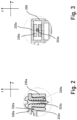
- the Figures 2 and 3 12 show a detailed sectional view of the attachment portions 230a and 330a.
- the light module 100 according to one of the preceding claims, wherein the at least one second fastening section 330a-b comprises an expanding section into which an associated screw 332a-b can be screwed, and wherein the at least one first fastening section 230a-b comprises a slot into which the Spreading section engages.
- the respective screw 332a-b can be screwed into the expansion section.
- the spreading section is thereby spread apart and presses outer surfaces of the spreading section against inner surfaces of the laughing hole.
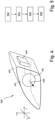
- FIG. 1 shows the lighting device 400 in the form of a headlight, shown schematically, for a motor vehicle.
- the lighting device 400 can also be a rear light, a blinker or a different type of lighting device for a motor vehicle.
- the light module 100 is located within the housing 402.
- the light module 200 is operated by the control unit 406 in such a way that the light module 100 emits a light distribution 408.
- a light exit opening of the housing 402 is closed by a transparent cover plate 410 through which the light distribution 408 passes.
- FIG. 1 shows a manufacturing method for adjusting the light module 100 in a schematic flowchart figure 1 .
- Means are provided for operating 502, in the first state, the light source assembly to generate a first light distribution which is coupled into the optics assembly.
- a second light distribution is emitted from the optics assembly.
- Means are provided to detect 504, in the first state, the second light distribution by means of a sensor.
- a displacement 506 of the optics assembly to the fixedly arranged light source assembly is carried out, specifically until a position is reached in which a desired second light distribution is present. With the light sources switched on, this displacement is carried out by means of the guide sections and the displacement tool.
- the color fringe at the edge of the light distribution is changed by the shift.
- the color fringe changes in thickness and coloring. If the color fringe is minimal or the coloring is as small as possible, this is recognized as the end position.
- the optics assembly 300 and the light source assembly 200 are fixed 508 to one another by means of the fastening sections 230a-b, 240a-b and to achieve the second state.
- an operator manually inserts the optics assembly into the light source assembly.
- the relative position of the optics assembly is initially not critical.
- the optics assembly is brought into an initial position, which represents a starting position for the method steps described above, by the engagement sections designed as adjustment ribs.
- the optics assembly is on the majority of the contact surfaces on the Reference plane pressed by spring force and then moved to the adjustment ribs along the adjustment axis or along the optical axis according to step 506 until the color fringe in the illumination box that has the sensor is correct, ie meets a predetermined quality feature.
- this position is then fixed using the two screws. These are screwed into the optics assembly, regardless of its relative position.
- the interface is spread and forms a frictional connection in the x and z direction and a positive connection in the y direction with the heat sink or the light source assembly. This is possible in any position within the defined adjustment range.
Abstract
Es wird ein Lichtmodul (100) für eine Kraftfahrzeugbeleuchtungseinrichtung bereitgestellt umfassend: eine Lichtquellen-Baugruppe (200) umfassend wenigstens eine Lichtquelleneinheit (210), wenigstens einen ersten Führungsabschnitt (220a-b) und wenigstens einen ersten Befestigungsabschnitt (230a-b); und eine Optik-Baugruppe (300) umfassend wenigstens ein Optikelement (310), wenigstens einen zweiten Führungsabschnitt (320a-b) und wenigstens einen zweiten Befestigungsabschnitt (330a-b), wobei die Lichtquellen-Baugruppe (200) und die Optik-Baugruppe (300) in einem ersten Zustand, insbesondere einem Justagezustand, mittels der ersten und zweiten Führungsabschnitte (220, 320) entlang einer Justageachse (J) zueinander verschiebbar sind, und wobei die Lichtquellen-Baugruppe (200) und die Optik-Baugruppe (300) in einem zweiten Zustand, insbesondere in einem justierten Endmontagezustand, mittels der ersten und zweiten Befestigungsabschnitte (230, 330) zueinander festgelegt sind.A light module (100) for a motor vehicle lighting device is provided, comprising: a light source assembly (200) comprising at least one light source unit (210), at least one first guide section (220a-b) and at least one first fastening section (230a-b); and an optics assembly (300) comprising at least one optics element (310), at least one second guide portion (320a-b) and at least one second attachment portion (330a-b), wherein the light source assembly (200) and the optics assembly ( 300) in a first state, in particular an adjustment state, by means of the first and second guide sections (220, 320) along an adjustment axis (J) can be displaced relative to one another, and wherein the light source assembly (200) and the optics assembly (300) in are fixed to one another in a second state, in particular in an adjusted final assembly state, by means of the first and second fastening sections (230, 330).
Description
Die Erfindung betrifft ein Lichtmodul, eine Kraftfahrzeugbeleuchtungseinrichtung und ein Fertigungsverfahren für das Lichtmodul.The invention relates to a light module, a motor vehicle lighting device and a manufacturing method for the light module.
Es ist bekannt, dass optisch wirksame Komponenten speziell bei Projektionslichtmodulen für Kraftfahrzeugscheinwerfer nur geringer Toleranzen bezüglich ihrer Einbauposition zueinander aufweisen dürfen, damit die abgestrahlte Lichtverteilung insbesondere im Randbereich keine ungewünschten Farbeffekte aufweist.It is known that optically effective components, especially in the case of projection light modules for motor vehicle headlights, may only have small tolerances with respect to their installation position in relation to one another, so that the emitted light distribution does not have any undesirable color effects, particularly in the edge region.
Die Probleme des Standes der Technik werden durch ein Lichtmodul gemäß dem Anspruch 1, durch eine Beleuchtungseinrichtung gemäß einem weiteren Anspruch sowie durch ein Fertigungsverfahren gemäß einem anderen Anspruch gelöst.The problems of the prior art are solved by a light module according to claim 1, by an illumination device according to a further claim and by a manufacturing method according to another claim.
Ein erster Aspekt der Beschreibung betrifft ein Lichtmodul für eine Kraftfahrzeugbeleuchtungseinrichtung. Dieses Lichtmodul umfasst: eine Lichtquellen-Baugruppe umfassend wenigstens eine Lichtquelleneinheit, wenigstens einen ersten Führungsabschnitt und wenigstens einen ersten Befestigungsabschnitt; und eine Optik-Baugruppe umfassend wenigstens ein Optikelement, wenigstens einen zweiten Führungsabschnitt und wenigstens einen zweiten Befestigungsabschnitt, wobei die Lichtquellen-Baugruppe und die Optik-Baugruppe in einem ersten Zustand, insbesondere einem Justagezustand, mittels der ersten und zweiten Führungsabschnitte entlang einer Justageachse zueinander verschiebbar sind, und wobei die Lichtquellen-Baugruppe und die Optik-Baugruppe in einem zweiten Zustand, insbesondere in einem justierten Endmontagezustand, mittels der ersten und zweiten Befestigungsabschnitte zueinander festgelegt sind.A first aspect of the description relates to a light module for a motor vehicle lighting device. This light module includes: a light source assembly including at least one light source unit, at least one first guide portion, and at least one first attachment portion; and an optics assembly comprising at least one optics element, at least one second guide section and at least one second fastening section, the light source assembly and the optics assembly being displaceable relative to one another in a first state, in particular an adjustment state, by means of the first and second guide sections along an adjustment axis are, and wherein the light source assembly and the optics assembly in a second state, in particular in an adjusted Final assembly state, are fixed to each other by means of the first and second mounting portions.
So wird eine Justage ermöglicht, bei der erreicht wird, dass der Brennpunkt der Optik-Baugruppe oder eines zugehörigen optischen Bauteils mit einer Blendenkante zusammenfälltAn adjustment is thus made possible in which it is achieved that the focal point of the optics assembly or an associated optical component coincides with a diaphragm edge
Durch das bereitgestellte Lichtmodul können insbesondere Randbereiche der abgestrahlten Lichtverteilung präziser eingestellt werden. Es entfällt eine freie Positionierung der Baugruppen im Raum, da die Führungsabschnitte eine Bewegung der Baugruppen zueinander auf eine Bewegung in einer gedachten Ebene begrenzen. Die gewünschte Position wird dann über die Befestigungsabschnitte festgelegt. Zusätzliche Befestigungsmittel können entfallen. Ein Knickpunkt der Lichtverteilung einer abgestrahlten Randlichtverteilung kann durch die Bewegung der Baugruppe entlang der Justageachse präziser eingestellt werden, was durch die im ersten Zustand vorhandene Längsführung der beiden Baugruppen zueinander möglich wird.The light module provided allows in particular edge regions of the emitted light distribution to be set more precisely. There is no free positioning of the assemblies in space, since the guide sections limit a movement of the assemblies relative to a movement in an imaginary plane. The desired position is then set using the attachment sections. Additional fasteners can be omitted. A break point in the light distribution of a radiated edge light distribution can be set more precisely by moving the assembly along the adjustment axis, which is made possible by the longitudinal guidance of the two assemblies relative to one another in the first state.
Ein vorteilhaftes Beispiel zeichnet sich dadurch aus, dass die Lichtquellen-Baugruppe wenigstens einen Befestigungsabschnitt zur Festlegung des Lichtmoduls zur Beleuchtungseinrichtung umfasst.An advantageous example is characterized in that the light source assembly includes at least one fastening section for fixing the light module to the lighting device.
Vorteilhaft wird die Baugruppe, die die Lichtquellen umfasst, zur Festlegung des Lichtmoduls genutzt. Die Referenzpunkte zum Scheinwerfer werden also an der Baugruppe angeordnet, auf der die Lichtquellen angeordnet sind. Eine präzise relativ zum Fahrzeug abgestrahlte Lichtabstrahlung vom Lichtmodul wird damit gewährleistet.The assembly, which includes the light sources, is advantageously used to fix the light module. The reference points to the headlight are therefore arranged on the assembly on which the light sources are arranged. This ensures that the light emitted by the light module is precise relative to the vehicle.
Ein vorteilhaftes Beispiel zeichnet sich dadurch aus, dass die Optik-Baugruppe eine Mehrzahl von Anpressflächen umfasst, welche in eine von dem wenigstens zweiten Führungsabschnitt abgewandte Richtung orientiert sind.An advantageous example is characterized in that the optics assembly comprises a plurality of contact surfaces which are oriented in a direction away from the at least second guide section.
Vorteilhaft kann während der Justage ein Niederhalter die Führungsabschnitte so stark aufeinanderdrücken, dass zwar eine axiale Verschiebung möglich, aber eine sichere Endposition beider Baugruppen zueinander über die Befestigungsabschnitte festlegbar ist.Advantageously, during the adjustment, a hold-down device can press the guide sections together so strongly that axial displacement is possible, but a safe end position of both assemblies relative to one another can be fixed via the fastening sections.
Ein vorteilhaftes Beispiel zeichnet sich dadurch aus, dass der wenigstens eine zweite Befestigungsabschnitt zwischen zwei gedachten zur Justageachse lotrechten Ebenen, die durch zwei voneinander beabstandete Anpressflächen verläuft, angeordnet ist.An advantageous example is characterized in that the at least one second fastening section is arranged between two imaginary planes which are perpendicular to the adjustment axis and which run through two contact surfaces spaced apart from one another.
Vorteilhaft befindet sich der zweite Befestigungsabschnitt in einem Bereich der Optik-Baugruppe, konkret der wenigstens eine erste Führungsabschnitt, der während der Justage zu beiden Seiten auf die Lichtquellen-Baugruppe gedrückt wird. Die finale Position der beiden Baugruppen kann so präziser erreicht und festgelegt werden.The second fastening section is advantageously located in a region of the optics assembly, specifically the at least one first guide section, which is pressed onto the light source assembly on both sides during the adjustment. The final position of the two assemblies can thus be reached and defined more precisely.
Ein vorteilhaftes Beispiel zeichnet sich dadurch aus, dass das Lichtmodul wenigstens zwei erste Befestigungsabschnitte und wenigstens zwei zweite Befestigungsabschnitte umfasst, wobei die ersten Befestigungsabschnitte und die zweiten Befestigungsabschnitte zumindest in dem zweiten Zustand paarweise voneinander beabstandet in einer gedachten Lotebene der Justageachse angeordnet sind.An advantageous example is characterized in that the light module comprises at least two first fastening sections and at least two second fastening sections, the first fastening sections and the second fastening sections being arranged in pairs spaced apart from one another in an imaginary perpendicular plane of the adjustment axis, at least in the second state.
Durch die symmetrische Anordnung der Befestigungsabschnitte wird die gewünschte finale Position der Baugruppen zueinander präziser erreicht und Toleranzen werden reduziert.Due to the symmetrical arrangement of the fastening sections, the desired final position of the assemblies relative to one another is achieved more precisely and tolerances are reduced.
Ein vorteilhaftes Beispiel zeichnet sich dadurch aus, dass das Lichtmodul wenigstens zwei erste Führungsabschnitte und wenigstens zwei zweite Führungsabschnitte umfasst, wobei die ersten Führungsabschnitte und die zweiten Führungsabschnitte paarweise eine gemeinsame Längserstreckung entlang einer jeweiligen Führungsachse aufweisen, und wobei die beiden Führungsachsen voneinander beabstandet und parallel zur Justageachse verlaufen.An advantageous example is characterized in that the light module comprises at least two first guide sections and at least two second guide sections, with the first guide sections and the second guide sections having a common longitudinal extent along a respective guide axis in pairs, and with the two guide axes spaced apart from one another and parallel to the alignment axis run.
Durch die symmetrische Anordnung der Führungsachsen wird die lineare Bewegung der Baugruppen zueinander während der Justage verbessert und Toleranzen reduziert.The symmetrical arrangement of the guide axes improves the linear movement of the assemblies relative to one another during adjustment and reduces tolerances.
Ein vorteilhaftes Beispiel zeichnet sich dadurch aus, dass die ersten und zweiten Führungsabschnitte aneinander anliegende Anlageflächen umfasst, welche parallel zur Justageachse verlaufen.An advantageous example is distinguished by the fact that the first and second guide sections comprise contact surfaces that rest against one another and run parallel to the adjustment axis.
Vorteilhaft erlauben die Anlageflächen im ersten Zustand eine Verschiebung der Baugruppen zueinander.In the first state, the contact surfaces advantageously allow the assemblies to be displaced in relation to one another.
Ein vorteilhaftes Beispiel zeichnet sich dadurch aus, dass der wenigstens eine zweite Befestigungsabschnitt einen Spreizabschnitt umfasst, in welchen eine zugeordnete Schraube eindrehbar ist, und dass der wenigstens eine erste Befestigungsabschnitt ein Langloch umfasst, in welches der Spreizabschnitt eingreift.An advantageous example is characterized in that the at least one second fastening section includes an expanding section into which an associated screw can be screwed, and that the at least one first fastening section includes an elongated hole into which the expanding section engages.
Vorteilhaft wird damit eine dauerhafte kraftschlüssige Verbindung beider Baugruppen bereitgestellt.A permanent non-positive connection of the two assemblies is thus advantageously provided.
Ein vorteilhaftes Beispiel zeichnet sich dadurch aus, dass die Optik-Baugruppe wenigstens einen Eingriffabschnitt, insbesondere zwei in einer gedachten Lotebene der Justageachse angeordnete Eingriffabschnitte, zur linearen Verschiebung der Optik-Baugruppe entlang der Justageachse umfasst.An advantageous example is characterized in that the optics assembly comprises at least one engagement section, in particular two engagement sections arranged in an imaginary perpendicular plane of the adjustment axis, for the linear displacement of the optics assembly along the adjustment axis.
Mittels des wenigstens einen Eingriffabschnitts wird in dem ersten Zustand die lineare Verschiebung der beiden Baugruppen zueinander vorgenommen.In the first state, the linear displacement of the two assemblies relative to one another is performed by means of the at least one engagement section.
Ein zweiter Aspekt der Beschreibung ist auf eine Kraftfahrzeugbeleuchtungseinrichtung gerichtet, die das Lichtmodul gemäß dem ersten Aspekt umfasst.A second aspect of the description is directed to a motor vehicle lighting device comprising the light module according to the first aspect.
Ein dritter Aspekt der Beschreibung betrifft ein Fertigungsverfahren zur Justage des Lichtmoduls gemäß dem ersten Aspekt. Das Fertigungsverfahren umfasst: Betreiben, in dem ersten Zustand, der Lichtquellen-Baugruppe zur Erzeugung einer ersten Lichtverteilung, die in die Optik-Baugruppe eingekoppelt wird, wobei von der Optik-Baugruppe eine zweite Lichtverteilung abgestrahlt wird; Erfassen, in dem ersten Zustand, der zweiten Lichtverteilung mittels eines Sensors; Verschieben, in dem ersten Zustand, mittels der Führungsabschnitte, der Optik-Baugruppe zur feststehend angeordneten Lichtquellen-Baugruppe bis zum Erreichen einer Position, in der eine gewünschte zweite Lichtverteilung vorliegt; und Festlegen, mittels der Befestigungsabschnitte, der Optik-Baugruppe und der Lichtquellen-Baugruppe zueinander zum Erreichen des zweiten Zustands.A third aspect of the description relates to a manufacturing method for adjusting the light module according to the first aspect. The manufacturing method includes: operating, in the first state, the light source assembly to generate a first light distribution, which is coupled into the optics assembly, wherein a second light distribution is emitted from the optics assembly; detecting, in the first state, the second light distribution by means of a sensor; Shifting, in the first state, by means of the guide sections, the optics assembly to the fixedly arranged light source assembly until a position is reached in which a desired second light distribution is present; and fixing, by means of the attachment portions, the optics assembly and the light source assembly to each other to achieve the second state.
In der Zeichnung zeigen
-
Figur 1 ein Lichtmodul in einer Explosionsansicht; -
Figuren 2 jeweilige Detailansichten von Befestigungsbereichen von und 3 Baugruppen des Lichtmoduls; -
Figur 4 eine das Lichtmodul umfassende Beleuchtungseinrichtung für ein Kraftfahrzeug in schematischer Form; und -
Figur 5 ein schematisches Ablaufdiagramm eines Fertigungsverfahrens für das Lichtmodul.
-
figure 1 a light module in an exploded view; -
figures 2 respective detailed views of fastening areas of and 3 assemblies of the light module; -
figure 4 a lighting device for a motor vehicle, comprising the light module, in schematic form; and -
figure 5 a schematic flowchart of a manufacturing process for the light module.
Folglich umfasst das Lichtmodul 100 wenigstens zwei erste Befestigungsabschnitte 230a-b und wenigstens zwei zweite Befestigungsabschnitte 330a-b, welche zumindest in dem zweiten Zustand paarweise voneinander beabstandet in einer gedachten Lotebene der Justageachse J angeordnet sind.Consequently, the
Weitergehend umfasst das Lichtmodul 100 wenigstens zwei erste Führungsabschnitte 220a-b und wenigstens zwei zweite Führungsabschnitte 320a-b, welche zumindest in dem zweiten Zustand paarweise eine gemeinsame Längserstreckung entlang einer jeweiligen Führungsachse aufweisen, wobei die beiden Führungsachsen voneinander beabstandet und parallel zur Justageachse J verlaufen. Die ersten und zweiten Führungsabschnitte 220-ab, 320a-b umfassen aneinander anliegende Anlageflächen 222a, 322a, welche parallel zur Justageachse J verlaufen.Furthermore, the
Die Lichtquelleneinheit 210 umfasst eine Leiterplatte 212, auf der Lichtquellenbauteile, beispielsweise Halbleiterlichtquellenbauteile, angeordnet sind. Die Normale der Lichtabstrahlfläche ist parallel zur Justageachse J ausgerichtet oder in Richtung der Justageachse J geneigt. Die in der Lichtquelleneinheit befindliche Blende besitzt die Blendenkante K, in deren Nähe die Transmissionsoptik 214 eine Zwischenlichtverteilung erzeugt. Der Brennpunkt F_310 kann durch die vorgeschlagene Justierung auf oder in die Nähe der Blendenkante K gebracht werden. Die Halbleiterlichtquellenbauteile strahlen Licht ab, das in die zur Leiterplatte 212 festgelegte Transmissionsoptik 214 eingekoppelt wird. Die Transmissionsoptik 214 ist als Primäroptik ausgebildet und erzeugt im Bereich der Blende eine Zwischenlichtverteilung. In einem Beispiel ist jeder Lichtquelle ein Transmissionsoptikelement zugeordnet, das als katadioptrische Vorsatzoptik ausgebildet ist. Ausgehend von der Transmissionsoptik 214 gelangt eine von dort abgestrahlte Lichtverteilung zu der Blende und von dort zu dem Optikelement 310, das als Projektionslinse ausgebildet ist. Die Zwischenlichtverteilung wird aus dem Bereich der Blendenkante ins Vorfeld des Fahrzeugs projiziert und so die Abblendlichtverteilung erzeugt. Die Projektionslinse ist in einem Linsenhalter 312 gehalten, in dem auch ein Wärmeschild 314 angeordnet ist. Ein Gehäuse 316 umgibt zumindest abschnittsweise den Linsenhalter 312.
Die Lichtquellen-Baugruppe 200 umfasst wenigstens zwei laterale Befestigungsabschnitte 202a-b zur Festlegung des Lichtmoduls 100 zu der Beleuchtungseinrichtung und damit zur Karosserie des Kraftfahrzeugs.The
The
Die Optik-Baugruppe 300 umfasst drei Anpressflächen 340a-c zum Anliegen eines Niederhalters einer Justagevorrichtung, welche dreieckförmig angeordnet sind. Die Anpressflächen 340a-c sind in eine von dem wenigstens zweiten Führungsabschnitt 320a-b abgewandte Richtung, insbesondere auf einer von den ersten Führungsabschnitten 220a-b abgewandten Seite 342 der Optik-Baugruppe 300, orientiert angeordnet, zeigen also von dem zugeordneten Bereich der Baugruppe 200 weg. Die zweiten Befestigungsabschnitte 330a-b sind zwischen zwei gedachten zur Justageachse J lotrechten Ebenen, die durch zwei voneinander beabstandete Anpressflächen 340a, 340c verläuft, angeordnet.The
Die Optik-Baugruppe 300 umfasst zwei in einer gedachten Lotebene der Justageachse J angeordnete Eingriffabschnitte 350a-b zur linearen Verschiebung der Optik-Baugruppe 300 entlang der Justageachse J mittels eines Verschiebewerkzeugs. Die Eingriffabschnitte 350a-b umfassen jeweils zwei, vorliegend voneinander abgewandte, Anlageflächen für das Verschiebewerkzeug. Die Eingriffabschnitte 350a-b sind lateral an der Optik-Baugruppe 300 angeordnet. Die Eingriffabschnitte 350a-b sind gegenüber einer Außenkontur der Optik-Baugruppe 300 zurückgesetzt angeordnet.The
Die
Mittel sind vorgesehen, um ein Erfassen 504, in dem ersten Zustand, der zweiten Lichtverteilung mittels eines Sensors durchzuführen.Means are provided to detect 504, in the first state, the second light distribution by means of a sensor.
In dem ersten Zustand wird ein Verschieben 506 der Optik-Baugruppe zur feststehend angeordneten Lichtquellen-Baugruppe durchgeführt, und zwar bis zum Erreichen einer Position, in der eine gewünschte zweite Lichtverteilung vorliegt. Diese Verschiebung wird bei eingeschalteten Lichtquellen mittels der Führungsabschnitte und dem Verschiebewerkzeug durchgeführt.In the first state, a
Insbesondere wird durch die Verschiebung der Farbsaum am Rand der Lichtverteilung verändert. Beim Verschieben bzw. Durchfahren der Positionen der Baugruppen zueinander verändert sich der Farbsaum in seiner Dicke und in der Einfärbung. Ist der Farbsaum minimal bzw. die Einfärbung möglichst gering, wird diese als Endposition erkannt.In particular, the color fringe at the edge of the light distribution is changed by the shift. When moving or moving through the positions of the assemblies to each other, the color fringe changes in thickness and coloring. If the color fringe is minimal or the coloring is as small as possible, this is recognized as the end position.
Im einem nächsten Schritt erfolgt ein Festlegen 508 der Optik-Baugruppe 300 und der Lichtquellen-Baugruppe 200 zueinander mittels der Befestigungsabschnitte 230a-b, 240a-b und zum Erreichen des zweiten Zustands.In a next step, the
Beispielsweise fügt vor dem Betreiben 502 der Lichtquellen ein Mitarbeiter von Hand die Optik-Baugruppe in die Lichtquellen-Baugruppe ein. Die relative Lage der Optik-Baugruppe ist dabei zunächst nicht entscheidend. Im weiteren Fertigungsprozess wird die Optik-Baugruppe durch die als Justagerippen ausgebildeten Eingriffabschnitte in eine Ausgangslage, die eine Startposition für die oben beschriebenen Verfahrensschritte darstellt, gebracht. Die Optik-Baugruppe wird über die die Mehrzahl der Anpressflächen auf die Referenzebene per Federkraft angedrückt und an den Justagerippen dann entlang der Justageachse bzw. entlang der optischen Achse gemäß dem Schritt 506 verschoben bis der Farbsaum im Ausleuchtkasten, der den Sensor aufweist, korrekt ist, d.h. ein vorgegebenes Qualitätsmerkmal erfüllt. Im Anschluss wird gemäß dem Schritt 508 diese Lage mittels der zwei Schrauben fixiert. Diese werden in die Optik-Baugruppe eingeschraubt, unabhängig davon in welcher relativen Lage diese sich befindet. Beim Einschrauben wird die Schnittstelle gespreizt und bildet in x- und z-Richtung einen Kraftschluss und in y-Richtung einen Formschluss mit dem Kühlkörper bzw. der Lichtquellen-Baugruppe. Dies ist jeder Position innerhalb des definierten Verstellbereichs möglich.For example, prior to operating 502 the light sources, an operator manually inserts the optics assembly into the light source assembly. The relative position of the optics assembly is initially not critical. In the further manufacturing process, the optics assembly is brought into an initial position, which represents a starting position for the method steps described above, by the engagement sections designed as adjustment ribs. The optics assembly is on the majority of the contact surfaces on the Reference plane pressed by spring force and then moved to the adjustment ribs along the adjustment axis or along the optical axis according to step 506 until the color fringe in the illumination box that has the sensor is correct, ie meets a predetermined quality feature. According to step 508, this position is then fixed using the two screws. These are screwed into the optics assembly, regardless of its relative position. When screwing in, the interface is spread and forms a frictional connection in the x and z direction and a positive connection in the y direction with the heat sink or the light source assembly. This is possible in any position within the defined adjustment range.
Claims (11)
Applications Claiming Priority (1)
| Application Number | Priority Date | Filing Date | Title |
|---|---|---|---|
| DE102022102582.9A DE102022102582A1 (en) | 2022-02-03 | 2022-02-03 | Light module, motor vehicle lighting device and manufacturing process |
Publications (1)
| Publication Number | Publication Date |
|---|---|
| EP4224057A1 true EP4224057A1 (en) | 2023-08-09 |
Family
ID=85172793
Family Applications (1)
| Application Number | Title | Priority Date | Filing Date |
|---|---|---|---|
| EP23154755.5A Pending EP4224057A1 (en) | 2022-02-03 | 2023-02-02 | Light module, motor vehicle lighting device and production method |
Country Status (4)
| Country | Link |
|---|---|
| US (1) | US20230243480A1 (en) |
| EP (1) | EP4224057A1 (en) |
| CN (1) | CN116538458A (en) |
| DE (1) | DE102022102582A1 (en) |
Citations (6)
| Publication number | Priority date | Publication date | Assignee | Title |
|---|---|---|---|---|
| DE202011108359U1 (en) * | 2011-11-28 | 2012-01-17 | Automotive Lighting Reutlingen Gmbh | Projection light module for a motor vehicle headlight |
| EP2693109A2 (en) * | 2012-08-03 | 2014-02-05 | Automotive Lighting Reutlingen GmbH | Light module |
| EP3757450A1 (en) * | 2019-06-27 | 2020-12-30 | ZKW Group GmbH | Illumination device of a motor vehicle headlight |
| FR3098279A1 (en) * | 2019-07-01 | 2021-01-08 | Valeo Vision | Motor vehicle projection assembly and Method of adjusting said projection assembly |
| DE212019000426U1 (en) * | 2019-05-21 | 2021-06-28 | Hasco Vision Technology Co., Ltd. | Headlight module, lighting device, headlight and vehicle |
| CN214147739U (en) * | 2020-11-23 | 2021-09-07 | 马瑞利汽车零部件(芜湖)有限公司 | Be applied to fixed knot of adjustable car light module of cut-off line in little space and construct |
Family Cites Families (2)
| Publication number | Priority date | Publication date | Assignee | Title |
|---|---|---|---|---|
| US20150062919A1 (en) | 2013-09-05 | 2015-03-05 | Ford Global Technologies, Llc | Optical lens positioning system and method |
| US11543095B2 (en) | 2018-04-06 | 2023-01-03 | Koito Manufacturing Co., Ltd. | Vehicle lamp with particular attachment of spatial light modulator to heat sink |
-
2022
- 2022-02-03 DE DE102022102582.9A patent/DE102022102582A1/en active Pending
-
2023
- 2023-02-02 US US18/163,867 patent/US20230243480A1/en active Pending
- 2023-02-02 CN CN202310051523.8A patent/CN116538458A/en active Pending
- 2023-02-02 EP EP23154755.5A patent/EP4224057A1/en active Pending
Patent Citations (6)
| Publication number | Priority date | Publication date | Assignee | Title |
|---|---|---|---|---|
| DE202011108359U1 (en) * | 2011-11-28 | 2012-01-17 | Automotive Lighting Reutlingen Gmbh | Projection light module for a motor vehicle headlight |
| EP2693109A2 (en) * | 2012-08-03 | 2014-02-05 | Automotive Lighting Reutlingen GmbH | Light module |
| DE212019000426U1 (en) * | 2019-05-21 | 2021-06-28 | Hasco Vision Technology Co., Ltd. | Headlight module, lighting device, headlight and vehicle |
| EP3757450A1 (en) * | 2019-06-27 | 2020-12-30 | ZKW Group GmbH | Illumination device of a motor vehicle headlight |
| FR3098279A1 (en) * | 2019-07-01 | 2021-01-08 | Valeo Vision | Motor vehicle projection assembly and Method of adjusting said projection assembly |
| CN214147739U (en) * | 2020-11-23 | 2021-09-07 | 马瑞利汽车零部件(芜湖)有限公司 | Be applied to fixed knot of adjustable car light module of cut-off line in little space and construct |
Also Published As
| Publication number | Publication date |
|---|---|
| US20230243480A1 (en) | 2023-08-03 |
| DE102022102582A1 (en) | 2023-08-03 |
| CN116538458A (en) | 2023-08-04 |
Similar Documents
| Publication | Publication Date | Title |
|---|---|---|
| DE102004058200B4 (en) | vehicle headlights | |
| DE102008036192B4 (en) | Automotive lighting device | |
| EP2799761B1 (en) | Light module for a motor vehicle headlamp | |
| EP2693109B1 (en) | Light module | |
| DE102012213844B4 (en) | Light module for vehicle headlights with two optical units and associated fastening devices | |
| WO2019211120A1 (en) | Projection headlight | |
| EP3593033A1 (en) | Lighting apparatus for vehicles and mounting method | |
| DE202017007315U1 (en) | Lighting device for a motor vehicle with a lighting module | |
| DE112014004124T5 (en) | laser scanning | |
| EP3671014B1 (en) | Led headlight module and led light module for use in such an led headlight module | |
| DE102014112931A1 (en) | Headlights for vehicles | |
| DE102012219007B4 (en) | Lighting device for a motor vehicle | |
| DE60034085T2 (en) | Motor vehicle headlight for producing two different light beams with a single light source | |
| EP4224057A1 (en) | Light module, motor vehicle lighting device and production method | |
| DE10109047A1 (en) | Lighting and signaling devices for vehicles or airplanes | |
| EP3452753A1 (en) | Method for arranging a circuit carrier and apparatus for arranging a circuit carrier | |
| DE102021125553A1 (en) | Luminaire unit | |
| WO2021209220A1 (en) | Illumination device for a motor vehicle headlight | |
| DE102012024977A1 (en) | Luminaire, in particular outdoor lamp for a motor vehicle, and method for producing such a lamp | |
| EP3789659A2 (en) | Base for a light conversion or illumination device | |
| DE19647218C1 (en) | Electrical pressure-actuated switch for motor vehicles | |
| EP2320132B1 (en) | Vehicle headlamp | |
| DE102021116638A1 (en) | Process for processing an optical component for a lighting device of a vehicle | |
| DE102021124889A1 (en) | Light module with a fastening device | |
| DE102021130929A1 (en) | Tolerance-reduced lighting device for vehicles |
Legal Events
| Date | Code | Title | Description |
|---|---|---|---|
| PUAI | Public reference made under article 153(3) epc to a published international application that has entered the european phase |
Free format text: ORIGINAL CODE: 0009012 |
|
| STAA | Information on the status of an ep patent application or granted ep patent |
Free format text: STATUS: THE APPLICATION HAS BEEN PUBLISHED |
|
| AK | Designated contracting states |
Kind code of ref document: A1 Designated state(s): AL AT BE BG CH CY CZ DE DK EE ES FI FR GB GR HR HU IE IS IT LI LT LU LV MC ME MK MT NL NO PL PT RO RS SE SI SK SM TR |
|
| STAA | Information on the status of an ep patent application or granted ep patent |
Free format text: STATUS: REQUEST FOR EXAMINATION WAS MADE |
|
| 17P | Request for examination filed |
Effective date: 20240122 |
|
| RBV | Designated contracting states (corrected) |
Designated state(s): AL AT BE BG CH CY CZ DE DK EE ES FI FR GB GR HR HU IE IS IT LI LT LU LV MC ME MK MT NL NO PL PT RO RS SE SI SK SM TR |