EP4224032A1 - Valve - Google Patents
Valve Download PDFInfo
- Publication number
- EP4224032A1 EP4224032A1 EP21875395.2A EP21875395A EP4224032A1 EP 4224032 A1 EP4224032 A1 EP 4224032A1 EP 21875395 A EP21875395 A EP 21875395A EP 4224032 A1 EP4224032 A1 EP 4224032A1
- Authority
- EP
- European Patent Office
- Prior art keywords
- valve
- pilot
- valve seat
- pilot valve
- sealing body
- Prior art date
- Legal status (The legal status is an assumption and is not a legal conclusion. Google has not performed a legal analysis and makes no representation as to the accuracy of the status listed.)
- Granted
Links
Images




Classifications
-
- F—MECHANICAL ENGINEERING; LIGHTING; HEATING; WEAPONS; BLASTING
- F16—ENGINEERING ELEMENTS AND UNITS; GENERAL MEASURES FOR PRODUCING AND MAINTAINING EFFECTIVE FUNCTIONING OF MACHINES OR INSTALLATIONS; THERMAL INSULATION IN GENERAL
- F16K—VALVES; TAPS; COCKS; ACTUATING-FLOATS; DEVICES FOR VENTING OR AERATING
- F16K1/00—Lift valves or globe valves, i.e. cut-off apparatus with closure members having at least a component of their opening and closing motion perpendicular to the closing faces
- F16K1/32—Details
- F16K1/34—Cutting-off parts, e.g. valve members, seats
- F16K1/44—Details of seats or valve members of double-seat valves
- F16K1/443—Details of seats or valve members of double-seat valves the seats being in series
-
- F—MECHANICAL ENGINEERING; LIGHTING; HEATING; WEAPONS; BLASTING
- F16—ENGINEERING ELEMENTS AND UNITS; GENERAL MEASURES FOR PRODUCING AND MAINTAINING EFFECTIVE FUNCTIONING OF MACHINES OR INSTALLATIONS; THERMAL INSULATION IN GENERAL
- F16K—VALVES; TAPS; COCKS; ACTUATING-FLOATS; DEVICES FOR VENTING OR AERATING
- F16K1/00—Lift valves or globe valves, i.e. cut-off apparatus with closure members having at least a component of their opening and closing motion perpendicular to the closing faces
- F16K1/32—Details
- F16K1/34—Cutting-off parts, e.g. valve members, seats
- F16K1/46—Attachment of sealing rings
-
- F—MECHANICAL ENGINEERING; LIGHTING; HEATING; WEAPONS; BLASTING
- F16—ENGINEERING ELEMENTS AND UNITS; GENERAL MEASURES FOR PRODUCING AND MAINTAINING EFFECTIVE FUNCTIONING OF MACHINES OR INSTALLATIONS; THERMAL INSULATION IN GENERAL
- F16K—VALVES; TAPS; COCKS; ACTUATING-FLOATS; DEVICES FOR VENTING OR AERATING
- F16K1/00—Lift valves or globe valves, i.e. cut-off apparatus with closure members having at least a component of their opening and closing motion perpendicular to the closing faces
- F16K1/32—Details
- F16K1/34—Cutting-off parts, e.g. valve members, seats
- F16K1/36—Valve members
-
- F—MECHANICAL ENGINEERING; LIGHTING; HEATING; WEAPONS; BLASTING
- F16—ENGINEERING ELEMENTS AND UNITS; GENERAL MEASURES FOR PRODUCING AND MAINTAINING EFFECTIVE FUNCTIONING OF MACHINES OR INSTALLATIONS; THERMAL INSULATION IN GENERAL
- F16K—VALVES; TAPS; COCKS; ACTUATING-FLOATS; DEVICES FOR VENTING OR AERATING
- F16K1/00—Lift valves or globe valves, i.e. cut-off apparatus with closure members having at least a component of their opening and closing motion perpendicular to the closing faces
- F16K1/32—Details
- F16K1/34—Cutting-off parts, e.g. valve members, seats
- F16K1/42—Valve seats
-
- F—MECHANICAL ENGINEERING; LIGHTING; HEATING; WEAPONS; BLASTING
- F16—ENGINEERING ELEMENTS AND UNITS; GENERAL MEASURES FOR PRODUCING AND MAINTAINING EFFECTIVE FUNCTIONING OF MACHINES OR INSTALLATIONS; THERMAL INSULATION IN GENERAL
- F16K—VALVES; TAPS; COCKS; ACTUATING-FLOATS; DEVICES FOR VENTING OR AERATING
- F16K17/00—Safety valves; Equalising valves, e.g. pressure relief valves
- F16K17/02—Safety valves; Equalising valves, e.g. pressure relief valves opening on surplus pressure on one side; closing on insufficient pressure on one side
- F16K17/04—Safety valves; Equalising valves, e.g. pressure relief valves opening on surplus pressure on one side; closing on insufficient pressure on one side spring-loaded
- F16K17/048—Safety valves; Equalising valves, e.g. pressure relief valves opening on surplus pressure on one side; closing on insufficient pressure on one side spring-loaded combined with other safety valves, or with pressure control devices
-
- F—MECHANICAL ENGINEERING; LIGHTING; HEATING; WEAPONS; BLASTING
- F16—ENGINEERING ELEMENTS AND UNITS; GENERAL MEASURES FOR PRODUCING AND MAINTAINING EFFECTIVE FUNCTIONING OF MACHINES OR INSTALLATIONS; THERMAL INSULATION IN GENERAL
- F16K—VALVES; TAPS; COCKS; ACTUATING-FLOATS; DEVICES FOR VENTING OR AERATING
- F16K31/00—Actuating devices; Operating means; Releasing devices
- F16K31/12—Actuating devices; Operating means; Releasing devices actuated by fluid
- F16K31/36—Actuating devices; Operating means; Releasing devices actuated by fluid in which fluid from the circuit is constantly supplied to the fluid motor
- F16K31/40—Actuating devices; Operating means; Releasing devices actuated by fluid in which fluid from the circuit is constantly supplied to the fluid motor with electrically-actuated member in the discharge of the motor
- F16K31/406—Actuating devices; Operating means; Releasing devices actuated by fluid in which fluid from the circuit is constantly supplied to the fluid motor with electrically-actuated member in the discharge of the motor acting on a piston
-
- F—MECHANICAL ENGINEERING; LIGHTING; HEATING; WEAPONS; BLASTING
- F16—ENGINEERING ELEMENTS AND UNITS; GENERAL MEASURES FOR PRODUCING AND MAINTAINING EFFECTIVE FUNCTIONING OF MACHINES OR INSTALLATIONS; THERMAL INSULATION IN GENERAL
- F16F—SPRINGS; SHOCK-ABSORBERS; MEANS FOR DAMPING VIBRATION
- F16F9/00—Springs, vibration-dampers, shock-absorbers, or similarly-constructed movement-dampers using a fluid or the equivalent as damping medium
- F16F9/32—Details
- F16F9/44—Means on or in the damper for manual or non-automatic adjustment; such means combined with temperature correction
- F16F9/46—Means on or in the damper for manual or non-automatic adjustment; such means combined with temperature correction allowing control from a distance, i.e. location of means for control input being remote from site of valves, e.g. on damper external wall
- F16F9/465—Means on or in the damper for manual or non-automatic adjustment; such means combined with temperature correction allowing control from a distance, i.e. location of means for control input being remote from site of valves, e.g. on damper external wall using servo control, the servo pressure being created by the flow of damping fluid, e.g. controlling pressure in a chamber downstream of a pilot passage
-
- F—MECHANICAL ENGINEERING; LIGHTING; HEATING; WEAPONS; BLASTING
- F16—ENGINEERING ELEMENTS AND UNITS; GENERAL MEASURES FOR PRODUCING AND MAINTAINING EFFECTIVE FUNCTIONING OF MACHINES OR INSTALLATIONS; THERMAL INSULATION IN GENERAL
- F16K—VALVES; TAPS; COCKS; ACTUATING-FLOATS; DEVICES FOR VENTING OR AERATING
- F16K17/00—Safety valves; Equalising valves, e.g. pressure relief valves
- F16K17/02—Safety valves; Equalising valves, e.g. pressure relief valves opening on surplus pressure on one side; closing on insufficient pressure on one side
- F16K17/04—Safety valves; Equalising valves, e.g. pressure relief valves opening on surplus pressure on one side; closing on insufficient pressure on one side spring-loaded
- F16K17/0413—Safety valves; Equalising valves, e.g. pressure relief valves opening on surplus pressure on one side; closing on insufficient pressure on one side spring-loaded in the form of closure plates
-
- F—MECHANICAL ENGINEERING; LIGHTING; HEATING; WEAPONS; BLASTING
- F16—ENGINEERING ELEMENTS AND UNITS; GENERAL MEASURES FOR PRODUCING AND MAINTAINING EFFECTIVE FUNCTIONING OF MACHINES OR INSTALLATIONS; THERMAL INSULATION IN GENERAL
- F16K—VALVES; TAPS; COCKS; ACTUATING-FLOATS; DEVICES FOR VENTING OR AERATING
- F16K17/00—Safety valves; Equalising valves, e.g. pressure relief valves
- F16K17/02—Safety valves; Equalising valves, e.g. pressure relief valves opening on surplus pressure on one side; closing on insufficient pressure on one side
- F16K17/04—Safety valves; Equalising valves, e.g. pressure relief valves opening on surplus pressure on one side; closing on insufficient pressure on one side spring-loaded
- F16K17/0493—Safety valves; Equalising valves, e.g. pressure relief valves opening on surplus pressure on one side; closing on insufficient pressure on one side spring-loaded with a spring other than a helicoidal spring
Definitions
- the present invention relates to a valve which controls a working fluid.
- a valve used to control a working fluid in various industrial fields includes a valve seat and a valve body contacting and separating from the valve seat and can adjust a pressure or flow rate of a working fluid by adjusting a valve opening degree.
- a spool valve in which a spool corresponding to a valve body moves in parallel to an opening corresponding to a valve seat, a butterfly valve in which a valve body has a rotation shaft, and a lift valve in which a valve body moves perpendicular to an opening corresponding to a valve seat are exemplified as typical valves.
- the lift valve is the most suitable for the flow rate and pressure control.
- lift valves may require extremely high flow rate control functions depending on the device in which they are used. For example, there is a demand for valve opening accuracy between the valve body and the valve seat relative to the stroke of the valve body and a demand for reliable sealing performance when the valve is closed.
- valves requiring extremely high flow rate control functions for example, a pilot valve used in a shock absorber or the like is exemplified. Since the lift valve used as the pilot valve controls the movement of the main valve with the control pressure in the pilot control chamber, reliable sealing performance is required when the valve is closed in addition to the valve opening accuracy between the valve body and the valve seat relative to the stroke of the valve body.
- Patent Citation 1 is an example of the lift valve used in the fluid control valve as the pilot valve.
- the fluid control valve illustrated therein includes a valve housing which has a first flow path communicating with a piston chamber of a shock absorber and a second flow path communicating with a reservoir chamber, a main valve which accomplishes a relief function between the first flow path and the second flow path, and a pilot valve which controls a pressure of a pilot control chamber involving with the opening and closing control of the main valve.
- the pilot valve can control the pressure of the pilot control chamber by adjusting a pilot valve opening degree according to a balance between a driving force of a solenoid applied to the valve body and a biasing force of the biasing means.
- Patent Citation 1 JP 2011-525962 A (Pages 10 to 12, FIG. 3a)
- the pilot valve illustrated in Patent Citation 1 is premised that a flat surface of the valve body disposed to face a valve seat opening abuts over the entire circumference and can be sealed without a circumferential gap when the valve body is seated on the valve seat.
- the valve body and the valve seat are separate bodies and move relative to each other, it is necessary to manufacture the valve with high accuracy and to assemble the valve with high accuracy in order to seal a circumferential gap when the valve body is seated on the valve seat.
- the pilot valve is repeatedly opened and closed depending on the control state. Accordingly, the collision between the valve body and the valve seat is repeated and the collision sound at that time becomes noise.
- the present invention has been made in view of such problems and an object thereof is to provide a valve capable of reliably blocking a gap between a valve body and a valve seat at least in a valve closed state and reducing noise.
- a valve according to the present invention is a valve including: a valve seat; and a valve body, wherein the valve body and the valve seat are apart from each other at a gap in a radial direction and are arranged to be relatively movable in a reciprocating manner, the valve further comprises a sealing body that is elastically deformable and that is formed in an annular shape, and the sealing body extends from one of the valve body and the valve seat so as to seal the gap.
- the radial gap between the valve body and the valve seat is sealed by the annular sealing body while the valve body and the valve seat move close to each other.
- the flow of the working fluid can be reliably stopped within the elastic deformation range of the sealing body and high precision valve manufacturing and assembly processes are not required. Further, since the elastically deformable annular sealing body provided in the valve body or the valve seat comes into contact with the valve seat or the valve body while the valve body and the valve seat move close to each other and the shock generated at the time of contact is reduced by the elastic deformation, the generation of noise can be prevented.
- one of the valve body and the valve seat has a regulation portion configured to regulate deformation of the sealing body. According to this preferable configuration, excessive deformation of the sealing body can be prevented.
- one of the valve body and the valve seat is provided with a convex portion which is protruded in an axial direction and remaining one of the valve body and the valve seat is provided with a concave portion which is recessed in the axial direction so that the convex portion is insertable into the concave portion, and the sealing body is formed to protrude radially outward from the convex portion.
- the convex portion supporting the sealing body in a cantilevered manner is disposed on the inner radial side of the concave portion, the outer peripheral portion of the sealing body can be widely used as an elastically deformable area.
- a large diameter portion which is provided on a proximal side of the convex portion is a regulation portion configured to regulate deformation of the sealing body. According to this preferable configuration, excessive deformation of the sealing body can be regulated with a simple configuration.
- the sealing body is formed of metal and has an inner radial portion that is fitted to an annular groove formed in the convex portion. According to this preferable configuration, both rigidity and deformation of the sealing body supported in a cantilevered manner can be achieved.
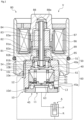
- a fluid control valve to which a valve according to an embodiment of the present invention is applied will be described with reference to FIGS. 1 to 7 .
- a pilot valve in the fluid control valve used in a shock absorber will be described as an example of the valve of the present invention, but can be applied to other uses.
- the top and bottom of the fluid control valve as viewed from the front in FIG. 1 will be described as the top and bottom of the fluid control valve.
- a description will be made such that the lower side of the paper where a main valve 60 is disposed is the lower side of the fluid control valve and the upper side of the paper where a solenoid 80 is disposed as a drive source is the upper side of the fluid control valve.
- a fluid control valve V of the present invention is fluidly connected to an absorber piston chamber P and a reservoir chamber R of a shock absorber A.
- the fluid control valve V opens a main valve 60 so that the working fluid flows out from a second flow path 13 to the reservoir chamber R. Accordingly, the fluid control valve V controls the flow rate of the working fluid flowing from the absorber piston chamber P toward the reservoir chamber R.
- the fluid control characteristic of the main valve 60 is adjusted by a pilot valve 50.
- the fluid control valve V controls the damping force of the shock absorber A.
- the fluid control valve V mainly includes a valve housing 10, a pilot valve 50 which is a valve, a main valve 60, and a solenoid 80.
- the pilot valve 50 is disposed at the upper end portion inside the valve housing 10. Further, the main valve 60 is disposed below the pilot valve 50 inside the valve housing 10.
- the pilot valve 50 includes a pilot valve body 51 which is a valve body and a pilot valve seat 40a which is a valve seat.
- the pilot valve 50 is opened and closed in such a manner that a sealing body 54 constituting the pilot valve body 51 contacts and separates from the pilot valve seat 40a.
- the main valve 60 includes a main valve body 61 and a main valve seat 45a.
- the main valve 60 is opened and closed in such a manner that an opening and closing portion 63 constituting the main valve body 61 contacts and separates from the main valve seat 45a.
- the solenoid 80 is connected to the valve housing 10 and applies a driving force to the pilot valve body 51.
- the solenoid 80 mainly includes a casing 81, a center post 82, a rod 83, a movable iron core 84, a coil spring 85, a coil 86, a sleeve 87, and bearings 88 and 89.
- the casing 81 includes a stepped cylindrical main body portion 81a into which the center post 82 is fitted and fixed from the axially lower side.
- the casing 81 is provided with an opening portion 81b which is continuous to the lower end of the main body portion 81a and is opened downward.
- the center post 82 is formed in a stepped cylindrical shape from a rigid body made of a magnetic material such as iron or silicon steel.
- the center post 82 includes a cylindrical main body portion 82a which extends in the axial direction.
- center post 82 is provided with an opening portion 82b which is continuous to the lower end of the main body portion 82a and is opened to the lower side of the center post 82.
- the rod 83 is formed in a cylindrical shape.
- the rod 83 is inserted through the center post 82 and is disposed to be movable in a reciprocating manner in the axial direction.
- the rod 83 is fitted and fixed to the movable iron core 84. Accordingly, when the solenoid 80 is energized, the rod 83 is moved while following the movable iron core 84 moving in the valve closing direction. Accordingly, the rod 83 moves the pilot valve body 51 in the valve closing direction, that is, toward the axially lower side.
- the upper end portion of the rod 83 is inserted through the bearing 88 and the lower end portion thereof is inserted through the bearing 89.
- the bearings 88 and 89 By these bearings 88 and 89, the movement of the rod 83 in the axial direction is guided. Therefore, the rod 83 is less likely to tilt in the radial direction when moving in the axial direction.
- the rod 83 is provided with a communication path 83a penetrating in the axial direction.
- the bearing 88 is provided with a communication groove 88a which extends in the axial direction. Accordingly, the influence of the working fluid during the movement of the rod 83 and the movable iron core 84 is reduced.
- the coil spring 85 is disposed between a pilot valve seat member 40 and the pilot valve body 51.
- the coil spring 85 biases the pilot valve body 51 in the valve opening direction of the pilot valve 50, that is, toward the axially upper side.
- the coil 86 is an excitation coil wound around the center post 82 through a bobbin.
- the sleeve 87 is formed in a bottomed cylindrical shape. Further, the bearings 88 and 89 guiding the movement of the rod 83 are fitted and fixed to the sleeve 87.
- valve housing 10 The components on the side of the valve housing 10 are the valve housing 10, the pilot valve 50, and the main valve 60.
- valve housing 10 is formed in a stepped cylindrical shape from a metal material or a resin material.
- a cylindrical portion 10a, a small-diameter bottomed cylindrical portion 10b, a medium-diameter bottomed cylindrical portion 10c, and a large-diameter bottomed cylindrical portion 10d are formed in the valve housing 10 in order from the axially upper side.
- the pilot valve body 51 is inserted into the cylindrical portion 10a from the axially upper side.
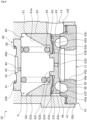
- the pilot valve body 51 is formed in a T shape in a cross-sectional view. Specifically, the pilot valve body 51 includes a cylindrical portion 52, a flange portion 53, and a sealing body 54.
- the upper end portion of the cylindrical portion 52 is provided with a concave portion 52a which is recessed toward the axially lower side.
- the lower end portion of the rod 83 comes into contact with the bottom surface of the concave portion 52a. Accordingly, the pilot valve body 51 which receives the biasing force of the coil spring 85 comes into press-contact with the rod 83.
- a communication path 52b which penetrates in the axial direction is formed on the inner radial side of the concave portion 52a.
- the cylindrical portion 52 has a stepped cylindrical shape which extends in the axial direction. Specifically, a large diameter portion 52c, a medium diameter portion 52d, and a small diameter portion 52e are formed in the cylindrical portion 52 in order from the axially upper side.
- the large diameter portion 52c, the medium diameter portion 52d, and the small diameter portion 52e constitute a convex portion of the valve body of this embodiment.
- the outer diameter of the large diameter portion 52c is substantially the same as the outer diameter of an annular convex portion 42 of the pilot valve seat member 40 to be described later. Further, the outer diameter of the medium diameter portion 52d is smaller than a circular concave portion 43 which is a concave portion of the pilot valve seat member 40 to be described later.
- the flange portion 53 which extends in the outer radial direction is continuous to the upper end of the large diameter portion 52c. Further, the medium diameter portion 52d having a diameter smaller than that of the large diameter portion 52c is continuous to the lower end of the large diameter portion 52c.
- the flange portion 53 has a disk shape which extends in the outer radial direction from the upper end portion of the cylindrical portion 52.
- An annular concave portion 53a which is recessed toward the axially upper side is formed at the lower end portion of the flange portion 53.
- the annular concave portion 53a is formed to have substantially the same outer radial as the outer radial of an annular concave portion 41 of the pilot valve seat member 40 to be described later. These outer radials are formed slightly larger than the outer radial of the coil spring 85.
- the coil spring 85 is disposed on the annular concave portion 53a and the annular concave portion 41 of the pilot valve seat member 40. Therefore, the coil spring 85 is guided by the outer peripheral surface of the annular concave portion 41 of the pilot valve seat member 40 and the annular concave portion 53a when compressed in the axial direction to prevent the coil spring 85 from being twisted or bent.
- the flange portion 53 is provided with a communication path 53b which penetrates in the axial direction.
- the communication path 53b communicates the cylindrical portion 10a of the valve housing 10 with the opening portion 82b (see FIG. 1 ) of the center post 82.
- the outer peripheral surface of the flange portion 53 is formed to be movable while sliding on the inner peripheral surface of the cylindrical portion 10a of the valve housing 10. Accordingly, the cylindrical portion 10a can guide the movement of the pilot valve body 51.
- the small diameter portion 52e having a diameter smaller than that of the medium diameter portion 52d is continuous to the lower end of the medium diameter portion 52d.
- annular groove 52f which is recessed toward the inner radial side is formed in the small diameter portion 52e to be continuous to the lower end surface of the medium diameter portion 52d.
- the inner radial side end portion of the disk-shaped sealing body 54 is fitted and fixed to the annular groove 52f. That is, the sealing body 54 is cantilevered by the annular groove 52f and protrudes in the outer radial direction from the annular groove 52f.
- the sealing body 54 is formed of a metal material and is elastically deformable in the axial direction (see FIG. 3 ). Needless to say, the material forming the sealing body 54 is not limited to metal.
- the outer diameter of the sealing body 54 is formed to be larger than the outer diameter of the annular convex portion 42 of the pilot valve seat member 40. Further, the upward bending deformation of the sealing body 54 is regulated by the large diameter portion 52c of the cylindrical portion 52 and the sealing body is deformable only in the elastic deformation area.
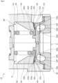
- the sealing body 54 can be seated on the pilot valve seat 40a while the sealing body 54 is elastically bent in the axial direction, more accurately, the sealing body 54 is bent toward the axially upper side.
- the small-diameter bottomed cylindrical portion 10b is continuous to the cylindrical portion 10a and is recessed toward the axially upper side while the inner side of the cylindrical portion 10a is enlarged in diameter.
- the pilot valve seat member 40 that is press-inserted from the axially lower side is integrally fixed to the small-diameter bottomed cylindrical portion 10b in a substantially sealed state.
- the pilot valve seat member 40 is formed in a disc shape from a metal material or a resin material.
- the annular concave portion 41 which is recessed toward the axially lower side is formed in the upper end portion of the pilot valve seat member 40.
- annular convex portion 42 which protrudes toward the axially upper side on the inner radial side of the annular concave portion 41 is formed in the upper end portion of the pilot valve seat member 40.
- the upper end portion of the annular convex portion 42 is the pilot valve seat 40a.
- a circular concave portion 43 which is a concave portion recessed toward the axially lower side in relation to the bottom surface of the annular concave portion 41 on the inner radial side of the annular convex portion 42 is formed at the upper end portion of the pilot valve seat member 40. Further, a communication path 44 which penetrates in the axial direction is formed on the bottom portion of the circular concave portion 43.
- the medium-diameter bottomed cylindrical portion 10c is continuous to the small-diameter bottomed cylindrical portion 10b and is recessed toward the axially upper side while the inner side of the small-diameter bottomed cylindrical portion 10b is enlarged in diameter.
- the main valve body 61 and a coil spring 64 are inserted into the medium-diameter bottomed cylindrical portion 10c from the axially lower side. Further, the upper end portion of the main valve seat member 45 press-inserted from the axially lower side is integrally fixed to the medium-diameter bottomed cylindrical portion 10c in a substantially sealed state.
- a pilot control chamber S is formed in a space inside the small-diameter bottomed cylindrical portion 10b and the medium-diameter bottomed cylindrical portion 10c of the valve housing 10.
- the pilot control chamber S is defined by the small-diameter bottomed cylindrical portion 10b, the medium-diameter bottomed cylindrical portion 10c, the pilot valve seat member 40, the pilot valve body 51, and the main valve body 61.
- the pilot control chamber S includes the circular concave portion 43 and the communication path 44 of the pilot valve seat member 40 and is the upstream flow path of the pilot valve body 51, that is, the upstream flow path of the pilot valve 50 (see FIG. 2 ).
- the main valve body 61 mainly includes a piston 62 which is formed in a U-shaped cylindrical shape in a cross-sectional view and an opening and closing portion 63. That is, the main valve body 61 is divided into two parts in the axial direction by the piston 62 and the opening and closing portion 63.
- the piston 62 includes a cylindrical portion 62a which is provided to extend in the axial direction and a bottom portion 62b which extends in the inner radial direction from the lower end portion of the cylindrical portion 62a and a through-hole 62c which penetrates in the axial direction is formed at the center of the bottom portion 62b.
- the coil spring 64 which biases the piston 62 in the valve closing direction, that is, toward the axially lower side is disposed between the bottom portion 62b of the piston 62 and the pilot valve seat member 40 in a compressed state.
- a leaf spring 65 which biases the opening and closing portion 63 in the valve closing direction, that is, toward the axially lower side is disposed between the piston 62 and the opening and closing portion 63.
- the piston 62 is provided with a concave portion 61a which is defined by the inner peripheral surface of the cylindrical portion 62a and the upper end surface of the bottom portion 62b and is recessed in a funnel shape toward the axially lower side.
- An annular concave portion 62d which is recessed toward the axially upper side is formed in the outer radial side lower end portion of the cylindrical portion 62a.
- the opening and closing portion 63 includes an annular outer radial side convex portion 63a which protrudes from the outer radial side end portion toward the axially upper side and an annular inner radial side convex portion 63b which protrudes from the radial center portion toward the axially upper side and an annular concave portion 63c is formed between the outer radial side convex portion 63a and the inner radial side convex portion 63b.
- the inner radial side convex portion 63b is inserted into the through-hole 62c of the piston 62.
- the opening and closing portion 63 is movable in the axial direction while sliding on the piston 62.
- the radial center portion of the opening and closing portion 63 is provided with a communication path 63d which penetrates in the axial direction. Additionally, the inside of the main valve body 61 communicates with the first flow path 11 through the communication path 63d of the opening and closing portion 63.
- the outer radial side lower end portion of the opening and closing portion 63 is provided with an annular concave portion 63e which is recessed toward the axially upper side.
- a lower end portion 63f of the opening and closing portion 63 located on the outer radial side of the annular concave portion 63e is seated on the main valve seat 45a in the valve closed state of the main valve 60.
- the leaf spring 65 is a spring which has a stepped circular ring and plate shape in cross-section and has a spring constant lower than that of the coil spring 64. Further, the leaf spring 65 mainly includes an annular inner radial plate portion 65a, a plurality of connection portions 65b which are bent upward from the outer radial end of the inner radial plate portion 65a and are bridged, and an annular outer radial plate portion 65c which is bent downward from the outer radial end of the connection portion 65b and is connected.
- the inner radial plate portion 65a and the outer radial plate portion 65c are substantially parallel to each other. Accordingly, the leaf spring 65 is deformable by receiving the axial load so that the bending angle of the connection portion 65b becomes small, that is, the axial distance between the inner radial plate portion 65a and the outer radial plate portion 65c becomes small.
- the leaf spring 65 is disposed so that the upper end surface of the inner radial plate portion 65a comes into contact with the lower end surface of the bottom portion 62b of the piston 62 and the lower end surface of the outer radial plate portion 65c comes into contact with the upper end surface of the outer radial side convex portion 63a of the opening and closing portion 63 in the valve closed state of the main valve 60. Further, the leaf spring 65 has a spring force smaller than that of the coil spring 64 when the main valve 60 is closed.
- the large-diameter bottomed cylindrical portion 10d is continuous to the medium-diameter bottomed cylindrical portion 10c and is recessed toward the axially upper side while the inner side of the medium-diameter bottomed cylindrical portion 10c is enlarged in diameter.
- the main valve seat member 45 that is press-inserted from the axially lower side is integrally fixed to the large-diameter bottomed cylindrical portion 10d in a substantially sealed state.
- the main valve seat member 45 is formed in a cylindrical shape having the first flow path 11 penetrating in the axial direction from a metal material or a resin material.
- the main valve seat member 45 includes a cylindrical portion 46 which extends in the axial direction and an annular flange portion 47 which extends toward the outer radial side from the lower end portion of the cylindrical portion 46. Further, in the main valve seat member 45, the flange portion 47 is press-inserted and fixed in a sealed state to the large-diameter bottomed cylindrical portion 10d from the axially lower side through a gasket in a state in which the upper end portion of the cylindrical portion 46 is inserted into the lower end portion of the medium-diameter bottomed cylindrical portion 10c.
- annular concave portion 48 which is recessed in a U shape in a cross-sectional view toward the axially lower side.
- a communication path 45b which penetrates in the axial direction and into which the working fluid flows from the absorber piston chamber P is formed on the inner radial side of the annular concave portion 48.
- annular land 49 is formed between the annular concave portion 48 and the communication path 45b on the inner radial side of the cylindrical portion 46.
- a plurality of communication grooves 49a which extend in the radial direction and communicate the annular concave portion 48 and the communication path 45b with each other are formed in the upper end portion of the land 49 in the circumferential direction. With this communication groove 49a, the working fluid can be introduced into the annular concave portion 48 and the annular concave portion 63e of the opening and closing portion 63 even in the valve closed state of the main valve 60.
- the communication path 45b of the main valve seat member 45, the annular concave portion 48, and the communication groove 49a constitute the upstream flow path of the main valve 60, that is, the first flow path 11 together with the lower end portion of the opening and closing portion 63.
- a communication groove 10e which has a downward L-shape in a cross-sectional view from the upper end to the side surface of the cylindrical portion 10a is formed on the outer surface of the valve housing 10. Specifically, the communication groove 10e extends toward the outer radial direction along the upper end surface of the valve housing 10 and then extends toward the axially lower side in a substantially orthogonal direction along the outer peripheral surface of the valve housing 10.
- the lower side end portion of the communication groove 10e extends downward in relation to the lower end of the opening portion 81b in a state in which the valve housing 10 is fitted to the opening portion 81b of the casing 81 and the working fluid can flow from the lower end of the communication groove 10e to the reservoir chamber R.
- the communication groove 10e constitutes a pilot downstream flow path 12 of the pilot valve 50.
- the pilot downstream flow path 12 is formed by the cylindrical portion 10a, the small-diameter bottomed cylindrical portion 10b, and the communication groove 10e of the valve housing 10, the upper end portion on the outer radial side of the annular convex portion 42 in the pilot valve seat member 40, the opening portion 81b of the casing 81, and the opening portion 82b of the center post 82.
- valve housing 10 is provided with a communication path 10f which extends from the medium-diameter bottomed cylindrical portion 10c toward the outer radial side and communicates the inside of the medium-diameter bottomed cylindrical portion 10c with the reservoir chamber R and the working fluid can flow from the communication path 10f into the reservoir chamber R.
- the communication path 10f constitutes the downstream flow path of the main valve 60, that is, the second flow path 13.
- the second flow path 13 is formed by the medium-diameter bottomed cylindrical portion 10c, the large-diameter bottomed cylindrical portion 10d, and the communication path 10f of the valve housing 10, the main valve body 61, and the main valve seat member 45.
- the fluid control valve V in the non-energized state will be described.
- the pilot valve 50 when the pilot valve 50 is not energized, the pilot valve body 51 is pressed toward the axially upper side by the biasing force of the coil spring 85. Accordingly, the sealing body 54 (see FIG. 2 ) of the pilot valve body 51 is separated from the pilot valve seat 40a and the pilot valve 50 is opened.
- the pilot valve opening degree at this embodiment becomes maximal in this embodiment.
- the shock absorber A In a non-energized state, when the shock absorber A is operated so that the pressure of the working fluid in the first flow path 11 becomes high, the working fluid passes through the communication path 63d (see FIG. 4 ) of the opening and closing portion 63 and the pilot control chamber S and flows from the pilot downstream flow path 12 into the reservoir chamber R. Also, as will be described later, the working fluid may also flow into the reservoir chamber R from the second flow path 13 depending on the pressure of the working fluid.
- the flow path cross-sectional area of the communication path 63d of the opening and closing portion 63 is formed to be narrow. Therefore, even when the pressure of the working fluid of the first flow path 11 is high, it is difficult for the pressure of the working fluid of the pilot control chamber S to increase in response to the pressure of the working fluid in the first flow path 11. Thus, a differential pressure is generated between the pressure of the working fluid of the first flow path 11 and the pressure of the working fluid in the pilot control chamber S. As the differential pressure increases, the main valve 60 is likely to be open.
- the pressure of the working fluid in the first flow path 11 sufficient to deform only the leaf spring 65 is assumed to be pressure P1 and the pressure of the working fluid in the first flow path 11 sufficient to deform the leaf spring 65 and the coil spring 64 is assumed to be the pressure P2.
- the pressure P1 becomes lower than the pressure P2 (P1 ⁇ P2).
- the pressure of the working fluid of the first flow path 11 is described as the "pressure Pin of the first flow path 11" and the pressure of the working fluid of the pilot control chamber S is described as the "pressure Ps of the pilot control chamber S".
- the reason why the differential pressure ⁇ P becomes small is a decrease in the pressure Pin of the first flow path 11 when the working fluid passes through the main valve 60 and flows from the second flow path 13 into the reservoir chamber R, a decrease in the pressure Pin of the first flow path 11 when the working fluid flows from the communication path 63d into the pilot control chamber S, or an increase in the pressure Ps of the pilot control chamber S when the volume of the pilot control chamber S becomes narrow due to the movement of the main valve body 61.
- the opening and closing operation of the main valve 60 will be described in more detail with specific examples.
- a force in which the coil spring 64 biases the piston 62 downward becomes larger than a force in which the leaf spring 65 biases the piston 62 upward.
- the leaf spring 65 is bent and deformed in the compression direction such that the inner radial plate portion 65a on the inner radial side is pushed toward the axially lower side by the coil spring 64 and the outer radial plate portion 65c on the outer radial side is supported in a contact state from the lower side of the outer radial side convex portion 63a of the opening and closing portion 63.
- the inner radial plate portion 65a of the leaf spring 65 and the bottom surface of the annular concave portion 63c of the opening and closing portion 63, and the outer radial plate portion 65c of the leaf spring 65 and the bottom surface of the concave portion 62d of the piston 62 are respectively separated from each other in the axial direction, so that the allowance for moving the opening and closing portion 63 in the axial direction is obtained.
- the lower end portion 63f of the opening and closing portion 63 is slightly separated from the main valve seat 45a and the main valve 60 is opened. Accordingly, the working fluid flows from the second flow path 13 to the reservoir chamber R through the main valve 60 (see the right half in FIG. 6 ).
- the valve opening degree of the main valve 60 becomes larger as the pressure Pin of the first flow path 11 becomes closer to the pressure P2.
- the opening and closing portion 63 moves against the biasing force of the leaf spring 65, the lower end surface of the inner radial plate portion 65a of the leaf spring 65 comes into press-contact with the bottom surface of the annular concave portion 63c and the upper end surface of the outer radial plate portion 65c of the leaf spring 65 approaches or contacts the bottom surface of the concave portion 62d of the piston 62.
- the lower end portion 63f of the opening and closing portion 63 is further separated from the main valve seat 45a and the main valve 60 is opened. Accordingly, the working fluid flows from the second flow path 13 to the reservoir chamber R through the main valve 60.
- valve opening degree of the main valve 60 when the pressure Pin of the first flow path 11 is equal to or higher than the pressure P2 (Pin ⁇ P2) becomes maximal in this embodiment (see the right half of FIG. 7 ).
- the working fluid that becomes surplus in the pilot control chamber S flows from the pilot downstream flow path 12 to the reservoir chamber R as the opening and closing portion 63 moves.
- the fluid control valve V can release the working fluid to the reservoir chamber R by opening the main valve 60 in approximately two stages according to the increase in the pressure Pin in the first flow path 11.
- the damping force of the shock absorber A is controlled to be minimum.
- the working fluid flows from the second flow path 13 to the reservoir chamber R through the main valve 60.
- the coil spring 64 extends and the valve opening degree decreases.
- the opening and closing portion 63 moves toward the axially upper side against the biasing force of the leaf spring 65 (see the right half of FIG. 6 ).
- the rod 83 fixed to the movable iron core 84 moves toward the axially lower side together with the pilot valve body 51.
- the pilot valve 50 is closed when the pilot valve opening degree decreases and a current exceeding a predetermined level is applied.
- the working fluid of the first flow path 11 flows from the pilot downstream flow path 12 to the reservoir chamber R in accordance with the operation of the shock absorber A as in the non-energized state. Further, as described above, the working fluid also flows from the second flow path 13 to the reservoir chamber R depending on the pressure Pin of the first flow path 11.
- the differential pressure ⁇ P is less likely to occur between the pressure Pin of the first flow path 11 and the pressure Ps of the pilot control chamber S and the main valve 60 is less likely to be opened. That is, the damping force of the shock absorber A can be increased.
- the damping force of the shock absorber A becomes minimal. That is, the damping force is controlled to be the smallest when the fluid control valve V is in the non-energized state.
- the differential pressure ⁇ P becomes smaller in a short time as the pilot valve opening degree of the pilot valve 50 becomes smaller. That is, the opening time of the main valve 60 is shortened as the pilot valve opening degree of the pilot valve 50 becomes smaller.
- the fluid control characteristics of the main valve 60 are controlled according to the pilot valve opening degree of the pilot valve 50. Accordingly, the fluid control valve V can variably control the damping force of the shock absorber A.
- the fluid control valve V when the pilot valve 50 is closed in the energized state, the fluid control valve V is in a state in which it is most difficult for the working fluid to pass through the pilot valve 50 and in a state in which it is difficult to open the main valve 60. Therefore, the fluid control valve V can maximize the damping force in the shock absorber A.
- a current value to be applied to the coil 86 that constitutes the solenoid 80 is set based on input parameters such as a vehicle speed, a vehicle acceleration/deceleration, a steering angle, a road surface condition, and a spring load.
- pilot valve 50 in the open state may be closed by setting a current value equal to or higher than a predetermined value.
- a gap between the pilot valve body 51 and the pilot valve seat 40a is sealed by the annular sealing body 54 while they move close to each other in a telescopic manner. Therefore, the cylindrical portion 52 and the flange portion 53 of the rigid pilot valve body 51 do not directly come into contact with the pilot valve seat member 40 including the pilot valve seat 40a, the flow of the working fluid can be reliably stopped within the elastic deformation range of the sealing body 54, and hence high precision valve manufacturing and assembly processes are not required.
- the sealing body 54 comes into contact with the annular convex portion 42 and the sealing body 54 is elastically deformed to reduce a shock at the time of contact while the pilot valve body 51 is moving closer to the pilot valve seat 40a, the generation of noise at the time of collision can be prevented.
- the small diameter portion 52e of the pilot valve body 51 supporting the sealing body 54 in a cantilevered manner is disposed on the inner radial side of the circular concave portion 43 of the pilot valve seat member 40, the outer peripheral portion of the sealing body 54 can be widely used as an elastically deformable area.
- the large diameter portion 52c is a regulation portion of this embodiment.
- the large diameter portion 52c which is formed on a proximal side of the small diameter portion 52e of the pilot valve body 51 is a regulation portion of this embodiment, excessive deformation of the sealing body 54 can be restricted with a simple configuration.
- the sealing body 54 is formed of metal and the inner radial portion is fitted to the annular groove 52f of the pilot valve body 51, deformation of the inner radial portion fitted in the annular groove 52f due to its own elastic force is reliably prevented. Accordingly, both rigidity and deformation of the cantilevered sealing body 54 can be achieved.
- the sealing body 54 is formed of metal, the applicable temperature range is higher than that of the sealing body made of resin. Accordingly, the temperature of the working fluid becomes low in cold regions. As in the shock absorber A which becomes hot in accordance with the driving of the piston, the working fluid can be stably used even when the working fluid is applied to a device in which the temperature changes greatly.
- the pilot valve seat member 40 since the working fluid flows into the circular concave portion 43 and the communication path 44 of the pilot valve seat member 40 to be applied to the sealing body 54 and the small diameter portion 52e when the pilot valve 50 is closed, the pilot valve is likely to be opened when a high pressure is generated in the first flow path 11.
- pilot valve 50 may be slightly opened by the elastic deformation of the sealing body 54 when a high pressure is generated in the first flow path 11 at the time of closing the pilot valve 50.
- pilot valve body 51 and the rod 83 are separated from each other, they can be easily manufactured while maintaining high valve closing performance compared to the configuration in which the pilot valve body and the rod are integrally formed with each other.
- the pilot valve has been described such that the convex portion is formed in the pilot valve body and the concave portion is formed in the pilot valve seat, but the present invention is not limited thereto.
- the concave portion may be formed in the pilot valve body and the convex portion may be formed in the pilot valve seat.
- pilot valve has been described such that the pilot valve body includes the sealing body, but the present invention is not limited thereto.
- the pilot valve seat may include the sealing body.
- sealing body has been described such that the sealing body extends radially outward from the outer peripheral surface of the convex portion, but the present invention is not limited thereto.
- the sealing body may extend radially inward from the inner peripheral surface of the concave portion.
- sealing body has been described such that the sealing body is formed of a metal material, but the present invention is not limited thereto.
- the sealing body may be formed of resin.
- the regulation portion has been described such that the regulation portion is the large diameter portion which is provided on a proximal side of the convex portion, but the present invention is not limited thereto.
- the regulation portion having a diameter larger than that of the large diameter portion may be integrally formed or a separate regulation member may be fixed to the cylindrical portion or the flange portion of the pilot valve body.
- the main valve body has been described such that the main valve body is divided into two parts of the piston and the opening and closing portion, but the present invention is not limited thereto.
- the base portion may be divided into two parts or more such that the base portion is divided into three parts or more including the base portion and the opening and closing portion. That is, the main valve may be openable in approximately three stages such that the rigid base portion is divided into two parts in the axial direction and a third biasing means having a spring force different from those of the first biasing means and the second biasing means is interposed between the upper base portion and the lower base portion.
- valve seat has been described as one formed in the valve seat member separated from the valve housing, but the present invention is not limited thereto.
- the valve seat may be integrally formed with the valve housing.
- the second biasing means has been described as the leaf spring, but the present invention is not limited thereto.
- the second biasing means may be changed to a coil spring, a disc spring, or the like as appropriate.
Landscapes
- Engineering & Computer Science (AREA)
- General Engineering & Computer Science (AREA)
- Mechanical Engineering (AREA)
- Magnetically Actuated Valves (AREA)
- Fluid-Driven Valves (AREA)
Abstract
Description
- The present invention relates to a valve which controls a working fluid.
- A valve used to control a working fluid in various industrial fields includes a valve seat and a valve body contacting and separating from the valve seat and can adjust a pressure or flow rate of a working fluid by adjusting a valve opening degree.
- As such a valve, a spool valve in which a spool corresponding to a valve body moves in parallel to an opening corresponding to a valve seat, a butterfly valve in which a valve body has a rotation shaft, and a lift valve in which a valve body moves perpendicular to an opening corresponding to a valve seat are exemplified as typical valves. Among these valves, the lift valve is the most suitable for the flow rate and pressure control.
- These lift valves may require extremely high flow rate control functions depending on the device in which they are used. For example, there is a demand for valve opening accuracy between the valve body and the valve seat relative to the stroke of the valve body and a demand for reliable sealing performance when the valve is closed.
- As the valves requiring extremely high flow rate control functions, for example, a pilot valve used in a shock absorber or the like is exemplified. Since the lift valve used as the pilot valve controls the movement of the main valve with the control pressure in the pilot control chamber, reliable sealing performance is required when the valve is closed in addition to the valve opening accuracy between the valve body and the valve seat relative to the stroke of the valve body.
- Patent Citation 1 is an example of the lift valve used in the fluid control valve as the pilot valve. The fluid control valve illustrated therein includes a valve housing which has a first flow path communicating with a piston chamber of a shock absorber and a second flow path communicating with a reservoir chamber, a main valve which accomplishes a relief function between the first flow path and the second flow path, and a pilot valve which controls a pressure of a pilot control chamber involving with the opening and closing control of the main valve. The pilot valve can control the pressure of the pilot control chamber by adjusting a pilot valve opening degree according to a balance between a driving force of a solenoid applied to the valve body and a biasing force of the biasing means.
- Patent Citation 1:
JP 2011-525962 A Pages 10 to 12, FIG. 3a) - The pilot valve illustrated in Patent Citation 1 is premised that a flat surface of the valve body disposed to face a valve seat opening abuts over the entire circumference and can be sealed without a circumferential gap when the valve body is seated on the valve seat. However, since the valve body and the valve seat are separate bodies and move relative to each other, it is necessary to manufacture the valve with high accuracy and to assemble the valve with high accuracy in order to seal a circumferential gap when the valve body is seated on the valve seat. In addition, the pilot valve is repeatedly opened and closed depending on the control state. Accordingly, the collision between the valve body and the valve seat is repeated and the collision sound at that time becomes noise.
- The present invention has been made in view of such problems and an object thereof is to provide a valve capable of reliably blocking a gap between a valve body and a valve seat at least in a valve closed state and reducing noise.
- In order to solve the foregoing problem, a valve according to the present invention is a valve including: a valve seat; and a valve body, wherein the valve body and the valve seat are apart from each other at a gap in a radial direction and are arranged to be relatively movable in a reciprocating manner, the valve further comprises a sealing body that is elastically deformable and that is formed in an annular shape, and the sealing body extends from one of the valve body and the valve seat so as to seal the gap. According to the aforesaid feature of the present invention, the radial gap between the valve body and the valve seat is sealed by the annular sealing body while the valve body and the valve seat move close to each other. Therefore, the flow of the working fluid can be reliably stopped within the elastic deformation range of the sealing body and high precision valve manufacturing and assembly processes are not required. Further, since the elastically deformable annular sealing body provided in the valve body or the valve seat comes into contact with the valve seat or the valve body while the valve body and the valve seat move close to each other and the shock generated at the time of contact is reduced by the elastic deformation, the generation of noise can be prevented.
- It may be preferable that one of the valve body and the valve seat has a regulation portion configured to regulate deformation of the sealing body. According to this preferable configuration, excessive deformation of the sealing body can be prevented.
- It may be preferable that one of the valve body and the valve seat is provided with a convex portion which is protruded in an axial direction and remaining one of the valve body and the valve seat is provided with a concave portion which is recessed in the axial direction so that the convex portion is insertable into the concave portion, and the sealing body is formed to protrude radially outward from the convex portion. According to this preferable configuration, since the convex portion supporting the sealing body in a cantilevered manner is disposed on the inner radial side of the concave portion, the outer peripheral portion of the sealing body can be widely used as an elastically deformable area.
- It may be preferable that a large diameter portion which is provided on a proximal side of the convex portion is a regulation portion configured to regulate deformation of the sealing body. According to this preferable configuration, excessive deformation of the sealing body can be regulated with a simple configuration.
- It may be preferable that the sealing body is formed of metal and has an inner radial portion that is fitted to an annular groove formed in the convex portion. According to this preferable configuration, both rigidity and deformation of the sealing body supported in a cantilevered manner can be achieved.
-
-
FIG. 1 is a cross-sectional view illustrating a fluid control valve to which a valve according to an embodiment of the present invention is applied. -
FIG. 2 is a cross-sectional view illustrating a state in which the valve applied to the fluid control valve in the embodiment is opened. -
FIG. 3 is a cross-sectional view illustrating a state in which the valve applied to the fluid control valve in the embodiment is closed. -
FIG. 4 is an enlarged cross-sectional view illustrating a main valve of the fluid control valve in the embodiment. -
FIG. 5 is a plan view illustrating a leaf spring constituting the main valve in the embodiment. -
FIG. 6 is a cross-sectional view sequentially illustrating a state in which the main valve of the fluid control valve in the embodiment is closed and a state in which the main valve is opened by compressing a second biasing means. -
FIG. 7 is a cross-sectional view sequentially illustrating a state in which the main valve of the fluid control valve in the embodiment is closed and a state in which the main valve is opened by compressing a first biasing means and a second biasing means. - A mode for carrying out a valve according to the present invention will be described below with reference to an embodiment.
- A fluid control valve to which a valve according to an embodiment of the present invention is applied will be described with reference to
FIGS. 1 to 7 . In the embodiment, a pilot valve in the fluid control valve used in a shock absorber will be described as an example of the valve of the present invention, but can be applied to other uses. Hereinafter, the top and bottom of the fluid control valve as viewed from the front inFIG. 1 will be described as the top and bottom of the fluid control valve. Specifically, a description will be made such that the lower side of the paper where amain valve 60 is disposed is the lower side of the fluid control valve and the upper side of the paper where asolenoid 80 is disposed as a drive source is the upper side of the fluid control valve. - Referring to
FIG. 1 , a fluid control valve V of the present invention is fluidly connected to an absorber piston chamber P and a reservoir chamber R of a shock absorber A. - When the absorber piston moves in the axial direction so that a pressure of a working fluid of a
first flow path 11 becomes high, the fluid control valve V opens amain valve 60 so that the working fluid flows out from asecond flow path 13 to the reservoir chamber R. Accordingly, the fluid control valve V controls the flow rate of the working fluid flowing from the absorber piston chamber P toward the reservoir chamber R. - Further, in the fluid control valve V, the fluid control characteristic of the
main valve 60 is adjusted by apilot valve 50. - Thus, the fluid control valve V controls the damping force of the shock absorber A.
- Next, the structure of the fluid control valve V will be described. As illustrated in
FIG. 1 , the fluid control valve V mainly includes avalve housing 10, apilot valve 50 which is a valve, amain valve 60, and asolenoid 80. - Among these, the
pilot valve 50 is disposed at the upper end portion inside thevalve housing 10. Further, themain valve 60 is disposed below thepilot valve 50 inside thevalve housing 10. - The
pilot valve 50 includes apilot valve body 51 which is a valve body and apilot valve seat 40a which is a valve seat. Thepilot valve 50 is opened and closed in such a manner that a sealingbody 54 constituting thepilot valve body 51 contacts and separates from thepilot valve seat 40a. - The
main valve 60 includes amain valve body 61 and amain valve seat 45a. Themain valve 60 is opened and closed in such a manner that an opening and closingportion 63 constituting themain valve body 61 contacts and separates from themain valve seat 45a. - First, the
solenoid 80 will be described. Thesolenoid 80 is connected to thevalve housing 10 and applies a driving force to thepilot valve body 51. - As illustrated in
FIG. 1 , thesolenoid 80 mainly includes acasing 81, acenter post 82, arod 83, amovable iron core 84, acoil spring 85, acoil 86, asleeve 87, andbearings - The
casing 81 includes a stepped cylindricalmain body portion 81a into which thecenter post 82 is fitted and fixed from the axially lower side. - Further, the
casing 81 is provided with anopening portion 81b which is continuous to the lower end of themain body portion 81a and is opened downward. - The
center post 82 is formed in a stepped cylindrical shape from a rigid body made of a magnetic material such as iron or silicon steel. - The
center post 82 includes a cylindricalmain body portion 82a which extends in the axial direction. - Further, the
center post 82 is provided with anopening portion 82b which is continuous to the lower end of themain body portion 82a and is opened to the lower side of thecenter post 82. - The
rod 83 is formed in a cylindrical shape. Therod 83 is inserted through thecenter post 82 and is disposed to be movable in a reciprocating manner in the axial direction. - Further, the
rod 83 is fitted and fixed to themovable iron core 84. Accordingly, when thesolenoid 80 is energized, therod 83 is moved while following themovable iron core 84 moving in the valve closing direction. Accordingly, therod 83 moves thepilot valve body 51 in the valve closing direction, that is, toward the axially lower side. - Further, the upper end portion of the
rod 83 is inserted through thebearing 88 and the lower end portion thereof is inserted through thebearing 89. By thesebearings rod 83 in the axial direction is guided. Therefore, therod 83 is less likely to tilt in the radial direction when moving in the axial direction. - Further, the
rod 83 is provided with acommunication path 83a penetrating in the axial direction. - The
bearing 88 is provided with acommunication groove 88a which extends in the axial direction. Accordingly, the influence of the working fluid during the movement of therod 83 and themovable iron core 84 is reduced. - The
coil spring 85 is disposed between a pilotvalve seat member 40 and thepilot valve body 51. - The
coil spring 85 biases thepilot valve body 51 in the valve opening direction of thepilot valve 50, that is, toward the axially upper side. - The
coil 86 is an excitation coil wound around thecenter post 82 through a bobbin. - The
sleeve 87 is formed in a bottomed cylindrical shape. Further, thebearings rod 83 are fitted and fixed to thesleeve 87. - Next, the configuration on the side of the
valve housing 10 will be described. The components on the side of thevalve housing 10 are thevalve housing 10, thepilot valve 50, and themain valve 60. - As illustrated in
FIG. 1 , thevalve housing 10 is formed in a stepped cylindrical shape from a metal material or a resin material. - A
cylindrical portion 10a, a small-diameter bottomedcylindrical portion 10b, a medium-diameter bottomedcylindrical portion 10c, and a large-diameter bottomedcylindrical portion 10d are formed in thevalve housing 10 in order from the axially upper side. - The
pilot valve body 51 is inserted into thecylindrical portion 10a from the axially upper side. - As illustrated in
FIG. 2 , thepilot valve body 51 is formed in a T shape in a cross-sectional view. Specifically, thepilot valve body 51 includes acylindrical portion 52, aflange portion 53, and a sealingbody 54. - The upper end portion of the
cylindrical portion 52 is provided with aconcave portion 52a which is recessed toward the axially lower side. The lower end portion of therod 83 comes into contact with the bottom surface of theconcave portion 52a. Accordingly, thepilot valve body 51 which receives the biasing force of thecoil spring 85 comes into press-contact with therod 83. - A
communication path 52b which penetrates in the axial direction is formed on the inner radial side of theconcave portion 52a. - Further, the
cylindrical portion 52 has a stepped cylindrical shape which extends in the axial direction. Specifically, alarge diameter portion 52c, amedium diameter portion 52d, and asmall diameter portion 52e are formed in thecylindrical portion 52 in order from the axially upper side. Thelarge diameter portion 52c, themedium diameter portion 52d, and thesmall diameter portion 52e constitute a convex portion of the valve body of this embodiment. - The outer diameter of the
large diameter portion 52c is substantially the same as the outer diameter of an annularconvex portion 42 of the pilotvalve seat member 40 to be described later. Further, the outer diameter of themedium diameter portion 52d is smaller than a circularconcave portion 43 which is a concave portion of the pilotvalve seat member 40 to be described later. - Accordingly, as illustrated in
FIG. 3 , in a state in which thesmall diameter portion 52e of thecylindrical portion 52 extends into the circularconcave portion 43 of the pilotvalve seat member 40 to be disposed in a telescopic manner, in other words, a state in which thesmall diameter portion 52e and the circularconcave portion 43 axially overlap each other, that is, radially overlap each other, each of the outer peripheral surfaces of themedium diameter portion 52d and thesmall diameter portion 52e is separated from the inner peripheral surface of the circularconcave portion 43 and a gap is formed therebetween. - The
flange portion 53 which extends in the outer radial direction is continuous to the upper end of thelarge diameter portion 52c. Further, themedium diameter portion 52d having a diameter smaller than that of thelarge diameter portion 52c is continuous to the lower end of thelarge diameter portion 52c. - The
flange portion 53 has a disk shape which extends in the outer radial direction from the upper end portion of thecylindrical portion 52. - An annular
concave portion 53a which is recessed toward the axially upper side is formed at the lower end portion of theflange portion 53. - The annular
concave portion 53a is formed to have substantially the same outer radial as the outer radial of an annularconcave portion 41 of the pilotvalve seat member 40 to be described later. These outer radials are formed slightly larger than the outer radial of thecoil spring 85. - The
coil spring 85 is disposed on the annularconcave portion 53a and the annularconcave portion 41 of the pilotvalve seat member 40. Therefore, thecoil spring 85 is guided by the outer peripheral surface of the annularconcave portion 41 of the pilotvalve seat member 40 and the annularconcave portion 53a when compressed in the axial direction to prevent thecoil spring 85 from being twisted or bent. - Further, the
flange portion 53 is provided with acommunication path 53b which penetrates in the axial direction. Thecommunication path 53b communicates thecylindrical portion 10a of thevalve housing 10 with theopening portion 82b (seeFIG. 1 ) of thecenter post 82. - Further, the outer peripheral surface of the
flange portion 53 is formed to be movable while sliding on the inner peripheral surface of thecylindrical portion 10a of thevalve housing 10. Accordingly, thecylindrical portion 10a can guide the movement of thepilot valve body 51. - The
small diameter portion 52e having a diameter smaller than that of themedium diameter portion 52d is continuous to the lower end of themedium diameter portion 52d. - An
annular groove 52f which is recessed toward the inner radial side is formed in thesmall diameter portion 52e to be continuous to the lower end surface of themedium diameter portion 52d. The inner radial side end portion of the disk-shaped sealingbody 54 is fitted and fixed to theannular groove 52f. That is, the sealingbody 54 is cantilevered by theannular groove 52f and protrudes in the outer radial direction from theannular groove 52f. - The sealing
body 54 is formed of a metal material and is elastically deformable in the axial direction (seeFIG. 3 ). Needless to say, the material forming the sealingbody 54 is not limited to metal. - The outer diameter of the sealing
body 54 is formed to be larger than the outer diameter of the annularconvex portion 42 of the pilotvalve seat member 40. Further, the upward bending deformation of the sealingbody 54 is regulated by thelarge diameter portion 52c of thecylindrical portion 52 and the sealing body is deformable only in the elastic deformation area. - Accordingly, as illustrated in
FIG. 3 , in a state in which thesmall diameter portion 52e of thecylindrical portion 52 extends into the circularconcave portion 43 of the pilotvalve seat member 40 to be disposed in a telescopic manner, as illustrated in the right half ofFIG. 3 , the sealingbody 54 can be seated on thepilot valve seat 40a while the sealingbody 54 is elastically bent in the axial direction, more accurately, the sealingbody 54 is bent toward the axially upper side. - Returning to the configuration of the
valve housing 10, the small-diameter bottomedcylindrical portion 10b is continuous to thecylindrical portion 10a and is recessed toward the axially upper side while the inner side of thecylindrical portion 10a is enlarged in diameter. - The pilot
valve seat member 40 that is press-inserted from the axially lower side is integrally fixed to the small-diameter bottomedcylindrical portion 10b in a substantially sealed state. - As illustrated in
FIG. 2 , the pilotvalve seat member 40 is formed in a disc shape from a metal material or a resin material. The annularconcave portion 41 which is recessed toward the axially lower side is formed in the upper end portion of the pilotvalve seat member 40. - Further, an annular
convex portion 42 which protrudes toward the axially upper side on the inner radial side of the annularconcave portion 41 is formed in the upper end portion of the pilotvalve seat member 40. The upper end portion of the annularconvex portion 42 is thepilot valve seat 40a. - Further, a circular
concave portion 43 which is a concave portion recessed toward the axially lower side in relation to the bottom surface of the annularconcave portion 41 on the inner radial side of the annularconvex portion 42 is formed at the upper end portion of the pilotvalve seat member 40. Further, acommunication path 44 which penetrates in the axial direction is formed on the bottom portion of the circularconcave portion 43. - Returning to the configuration of the
valve housing 10, the medium-diameter bottomedcylindrical portion 10c is continuous to the small-diameter bottomedcylindrical portion 10b and is recessed toward the axially upper side while the inner side of the small-diameter bottomedcylindrical portion 10b is enlarged in diameter. - The
main valve body 61 and acoil spring 64 are inserted into the medium-diameter bottomedcylindrical portion 10c from the axially lower side. Further, the upper end portion of the mainvalve seat member 45 press-inserted from the axially lower side is integrally fixed to the medium-diameter bottomedcylindrical portion 10c in a substantially sealed state. - In addition, as illustrated in
FIG. 1 , a pilot control chamber S is formed in a space inside the small-diameter bottomedcylindrical portion 10b and the medium-diameter bottomedcylindrical portion 10c of thevalve housing 10. The pilot control chamber S is defined by the small-diameter bottomedcylindrical portion 10b, the medium-diameter bottomedcylindrical portion 10c, the pilotvalve seat member 40, thepilot valve body 51, and themain valve body 61. - That is, the pilot control chamber S includes the circular
concave portion 43 and thecommunication path 44 of the pilotvalve seat member 40 and is the upstream flow path of thepilot valve body 51, that is, the upstream flow path of the pilot valve 50 (seeFIG. 2 ). - As illustrated in
FIG. 4 , themain valve body 61 mainly includes apiston 62 which is formed in a U-shaped cylindrical shape in a cross-sectional view and an opening and closingportion 63. That is, themain valve body 61 is divided into two parts in the axial direction by thepiston 62 and the opening and closingportion 63. - The
piston 62 includes acylindrical portion 62a which is provided to extend in the axial direction and abottom portion 62b which extends in the inner radial direction from the lower end portion of thecylindrical portion 62a and a through-hole 62c which penetrates in the axial direction is formed at the center of thebottom portion 62b. - Further, the
coil spring 64 which biases thepiston 62 in the valve closing direction, that is, toward the axially lower side is disposed between thebottom portion 62b of thepiston 62 and the pilotvalve seat member 40 in a compressed state. Further, aleaf spring 65 which biases the opening and closingportion 63 in the valve closing direction, that is, toward the axially lower side is disposed between thepiston 62 and the opening and closingportion 63. - Further, the
piston 62 is provided with aconcave portion 61a which is defined by the inner peripheral surface of thecylindrical portion 62a and the upper end surface of thebottom portion 62b and is recessed in a funnel shape toward the axially lower side. - An annular
concave portion 62d which is recessed toward the axially upper side is formed in the outer radial side lower end portion of thecylindrical portion 62a. - The opening and closing
portion 63 includes an annular outer radial sideconvex portion 63a which protrudes from the outer radial side end portion toward the axially upper side and an annular inner radial sideconvex portion 63b which protrudes from the radial center portion toward the axially upper side and an annularconcave portion 63c is formed between the outer radial sideconvex portion 63a and the inner radial sideconvex portion 63b. The inner radial sideconvex portion 63b is inserted into the through-hole 62c of thepiston 62. - In a state in which the inner radial side
convex portion 63b of the opening and closingportion 63 is inserted into the through-hole 62c of thepiston 62, the outer peripheral surface of the inner radial sideconvex portion 63b and the inner peripheral surface of thebottom portion 62b of thepiston 62 are formed to be substantially parallel to each other. Therefore, the opening and closingportion 63 is movable in the axial direction while sliding on thepiston 62. - The radial center portion of the opening and closing
portion 63 is provided with acommunication path 63d which penetrates in the axial direction. Additionally, the inside of themain valve body 61 communicates with thefirst flow path 11 through thecommunication path 63d of the opening and closingportion 63. - The outer radial side lower end portion of the opening and closing
portion 63 is provided with an annularconcave portion 63e which is recessed toward the axially upper side. Alower end portion 63f of the opening and closingportion 63 located on the outer radial side of the annularconcave portion 63e is seated on themain valve seat 45a in the valve closed state of themain valve 60. - As illustrated in
FIGS. 4 and5 , theleaf spring 65 is a spring which has a stepped circular ring and plate shape in cross-section and has a spring constant lower than that of thecoil spring 64. Further, theleaf spring 65 mainly includes an annular innerradial plate portion 65a, a plurality ofconnection portions 65b which are bent upward from the outer radial end of the innerradial plate portion 65a and are bridged, and an annular outerradial plate portion 65c which is bent downward from the outer radial end of theconnection portion 65b and is connected. - In the
leaf spring 65, the innerradial plate portion 65a and the outerradial plate portion 65c are substantially parallel to each other. Accordingly, theleaf spring 65 is deformable by receiving the axial load so that the bending angle of theconnection portion 65b becomes small, that is, the axial distance between the innerradial plate portion 65a and the outerradial plate portion 65c becomes small. - The
leaf spring 65 is disposed so that the upper end surface of the innerradial plate portion 65a comes into contact with the lower end surface of thebottom portion 62b of thepiston 62 and the lower end surface of the outerradial plate portion 65c comes into contact with the upper end surface of the outer radial sideconvex portion 63a of the opening and closingportion 63 in the valve closed state of themain valve 60. Further, theleaf spring 65 has a spring force smaller than that of thecoil spring 64 when themain valve 60 is closed. - Returning to the configuration of the
valve housing 10, the large-diameter bottomedcylindrical portion 10d is continuous to the medium-diameter bottomedcylindrical portion 10c and is recessed toward the axially upper side while the inner side of the medium-diameter bottomedcylindrical portion 10c is enlarged in diameter. - The main
valve seat member 45 that is press-inserted from the axially lower side is integrally fixed to the large-diameter bottomedcylindrical portion 10d in a substantially sealed state. - As illustrated in
FIG. 4 , the mainvalve seat member 45 is formed in a cylindrical shape having thefirst flow path 11 penetrating in the axial direction from a metal material or a resin material. - The main
valve seat member 45 includes acylindrical portion 46 which extends in the axial direction and anannular flange portion 47 which extends toward the outer radial side from the lower end portion of thecylindrical portion 46. Further, in the mainvalve seat member 45, theflange portion 47 is press-inserted and fixed in a sealed state to the large-diameter bottomedcylindrical portion 10d from the axially lower side through a gasket in a state in which the upper end portion of thecylindrical portion 46 is inserted into the lower end portion of the medium-diameter bottomedcylindrical portion 10c. - Further, the upper end portion of the
cylindrical portion 46 is provided with an annularconcave portion 48 which is recessed in a U shape in a cross-sectional view toward the axially lower side. Acommunication path 45b which penetrates in the axial direction and into which the working fluid flows from the absorber piston chamber P is formed on the inner radial side of the annularconcave portion 48. - Further, an
annular land 49 is formed between the annularconcave portion 48 and thecommunication path 45b on the inner radial side of thecylindrical portion 46. A plurality ofcommunication grooves 49a which extend in the radial direction and communicate the annularconcave portion 48 and thecommunication path 45b with each other are formed in the upper end portion of theland 49 in the circumferential direction. With thiscommunication groove 49a, the working fluid can be introduced into the annularconcave portion 48 and the annularconcave portion 63e of the opening and closingportion 63 even in the valve closed state of themain valve 60. - The
communication path 45b of the mainvalve seat member 45, the annularconcave portion 48, and thecommunication groove 49a constitute the upstream flow path of themain valve 60, that is, thefirst flow path 11 together with the lower end portion of the opening and closingportion 63. - Returning to
FIG. 1 , acommunication groove 10e which has a downward L-shape in a cross-sectional view from the upper end to the side surface of thecylindrical portion 10a is formed on the outer surface of thevalve housing 10. Specifically, thecommunication groove 10e extends toward the outer radial direction along the upper end surface of thevalve housing 10 and then extends toward the axially lower side in a substantially orthogonal direction along the outer peripheral surface of thevalve housing 10. - Further, the lower side end portion of the
communication groove 10e extends downward in relation to the lower end of theopening portion 81b in a state in which thevalve housing 10 is fitted to theopening portion 81b of thecasing 81 and the working fluid can flow from the lower end of thecommunication groove 10e to the reservoir chamber R. - Accordingly, the
communication groove 10e constitutes a pilotdownstream flow path 12 of thepilot valve 50. - More specifically, the pilot
downstream flow path 12 is formed by thecylindrical portion 10a, the small-diameter bottomedcylindrical portion 10b, and thecommunication groove 10e of thevalve housing 10, the upper end portion on the outer radial side of the annularconvex portion 42 in the pilotvalve seat member 40, theopening portion 81b of thecasing 81, and theopening portion 82b of thecenter post 82. - Further, as illustrated in
FIG. 4 , thevalve housing 10 is provided with acommunication path 10f which extends from the medium-diameter bottomedcylindrical portion 10c toward the outer radial side and communicates the inside of the medium-diameter bottomedcylindrical portion 10c with the reservoir chamber R and the working fluid can flow from thecommunication path 10f into the reservoir chamber R. - Accordingly, the
communication path 10f constitutes the downstream flow path of themain valve 60, that is, thesecond flow path 13. - More specifically, the
second flow path 13 is formed by the medium-diameter bottomedcylindrical portion 10c, the large-diameter bottomedcylindrical portion 10d, and thecommunication path 10f of thevalve housing 10, themain valve body 61, and the mainvalve seat member 45. - Next, the operation of the fluid control valve V, mainly the opening and closing operations of the
pilot valve 50 and themain valve 60 will be described with reference toFIGS. 1 to 7 . - First, the fluid control valve V in the non-energized state will be described. Referring to
FIGS. 1 and2 , when thepilot valve 50 is not energized, thepilot valve body 51 is pressed toward the axially upper side by the biasing force of thecoil spring 85. Accordingly, the sealing body 54 (seeFIG. 2 ) of thepilot valve body 51 is separated from thepilot valve seat 40a and thepilot valve 50 is opened. The pilot valve opening degree at this embodiment becomes maximal in this embodiment. - In a non-energized state, when the shock absorber A is operated so that the pressure of the working fluid in the
first flow path 11 becomes high, the working fluid passes through thecommunication path 63d (seeFIG. 4 ) of the opening and closingportion 63 and the pilot control chamber S and flows from the pilotdownstream flow path 12 into the reservoir chamber R. Also, as will be described later, the working fluid may also flow into the reservoir chamber R from thesecond flow path 13 depending on the pressure of the working fluid. - In the fluid control valve V, the flow path cross-sectional area of the
communication path 63d of the opening and closingportion 63 is formed to be narrow. Therefore, even when the pressure of the working fluid of thefirst flow path 11 is high, it is difficult for the pressure of the working fluid of the pilot control chamber S to increase in response to the pressure of the working fluid in thefirst flow path 11. Thus, a differential pressure is generated between the pressure of the working fluid of thefirst flow path 11 and the pressure of the working fluid in the pilot control chamber S. As the differential pressure increases, themain valve 60 is likely to be open. - Based on this, in this embodiment, with respect to the pressure of the working fluid in the pilot control chamber S, the pressure of the working fluid in the
first flow path 11 sufficient to deform only theleaf spring 65 is assumed to be pressure P1 and the pressure of the working fluid in thefirst flow path 11 sufficient to deform theleaf spring 65 and thecoil spring 64 is assumed to be the pressure P2. Here, the pressure P1 becomes lower than the pressure P2 (P1 < P2). Additionally, in the following description, the pressure of the working fluid of thefirst flow path 11 is described as the "pressure Pin of thefirst flow path 11" and the pressure of the working fluid of the pilot control chamber S is described as the "pressure Ps of the pilot control chamber S". - When the differential pressure ΔP (= Pin - Ps) between the pressure Pin of the
first flow path 11 and the pressure Ps of the pilot control chamber S becomes small after themain valve 60 is opened, themain valve 60 is closed. - The reason why the differential pressure ΔP becomes small is a decrease in the pressure Pin of the
first flow path 11 when the working fluid passes through themain valve 60 and flows from thesecond flow path 13 into the reservoir chamber R, a decrease in the pressure Pin of thefirst flow path 11 when the working fluid flows from thecommunication path 63d into the pilot control chamber S, or an increase in the pressure Ps of the pilot control chamber S when the volume of the pilot control chamber S becomes narrow due to the movement of themain valve body 61. Hereinafter, the opening and closing operation of themain valve 60 will be described in more detail with specific examples. - Referring to
FIGS. 1 and6 , for example, when the pressure Pin of thefirst flow path 11 is lower than the pressure P1 (Pin < P1), such as when the absorber piston in the shock absorber A reciprocates with a minute stroke while traveling on a smooth road surface, in themain valve body 61, thelower end portion 63f of the opening and closingportion 63 is seated on themain valve seat 45a and themain valve 60 is closed due to the biasing force of thecoil spring 64 and theleaf spring 65. - Referring to the left half of
FIG. 6 , in the valve closed state of themain valve 60, a force in which thecoil spring 64 biases thepiston 62 downward becomes larger than a force in which theleaf spring 65 biases thepiston 62 upward. Accordingly, theleaf spring 65 is bent and deformed in the compression direction such that the innerradial plate portion 65a on the inner radial side is pushed toward the axially lower side by thecoil spring 64 and the outerradial plate portion 65c on the outer radial side is supported in a contact state from the lower side of the outer radial sideconvex portion 63a of the opening and closingportion 63. At this time, the innerradial plate portion 65a of theleaf spring 65 and the bottom surface of the annularconcave portion 63c of the opening and closingportion 63, and the outerradial plate portion 65c of theleaf spring 65 and the bottom surface of theconcave portion 62d of thepiston 62 are respectively separated from each other in the axial direction, so that the allowance for moving the opening and closingportion 63 in the axial direction is obtained. - Referring to
FIGS. 1 and6 , for example, when the pressure Pin of thefirst flow path 11 is equal to or higher than the pressure P1 and lower than the pressure P2 (P2 > Pin ≥ P1), such as when the absorber piston in the shock absorber A reciprocates repeatedly with small strokes when traveling on an uneven road surface, only the opening and closingportion 63 moves toward the axially upper side against the biasing force of theleaf spring 65. - That is, the
lower end portion 63f of the opening and closingportion 63 is slightly separated from themain valve seat 45a and themain valve 60 is opened. Accordingly, the working fluid flows from thesecond flow path 13 to the reservoir chamber R through the main valve 60 (see the right half inFIG. 6 ). - At this time, the working fluid that becomes surplus in the pilot control chamber S flows into the reservoir chamber R from the pilot
downstream flow path 12 as only the opening and closingportion 63 moves. - In addition, since the
main valve 60 is closed as the differential pressure ΔP decreases as described above, the valve opening degree of themain valve 60 becomes larger as the pressure Pin of thefirst flow path 11 becomes closer to the pressure P2. - Further, when the opening and closing
portion 63 moves against the biasing force of theleaf spring 65, the lower end surface of the innerradial plate portion 65a of theleaf spring 65 comes into press-contact with the bottom surface of the annularconcave portion 63c and the upper end surface of the outerradial plate portion 65c of theleaf spring 65 approaches or contacts the bottom surface of theconcave portion 62d of thepiston 62. Accordingly, since the upper end surface of the outerradial plate portion 65c of theleaf spring 65 comes into contact with the bottom surface of theconcave portion 62d of thepiston 62 when the pressure Pin of the working fluid in thefirst flow path 11 is the pressure P2, the pressure applied from the working fluid of thefirst flow path 11 is likely to be applied to thepiston 62 through the opening and closingportion 63. - Referring to
FIGS. 1 and7 , for example, when the pressure Pin of thefirst flow path 11 is equal to or higher than the pressure P2 (Pin ≥ P2), such as when the absorber piston in shock absorber A tries to make a large stroke in order to overcome a step on the road surface, not only the opening and closingportion 63 but also thepiston 62 move toward the axially upper side against the biasing force of thecoil spring 64 and theleaf spring 65. - That is, the
lower end portion 63f of the opening and closingportion 63 is further separated from themain valve seat 45a and themain valve 60 is opened. Accordingly, the working fluid flows from thesecond flow path 13 to the reservoir chamber R through themain valve 60. - In addition, the valve opening degree of the
main valve 60 when the pressure Pin of thefirst flow path 11 is equal to or higher than the pressure P2 (Pin ≥ P2) becomes maximal in this embodiment (see the right half ofFIG. 7 ). - Further, the working fluid that becomes surplus in the pilot control chamber S flows from the pilot
downstream flow path 12 to the reservoir chamber R as the opening and closingportion 63 moves. - In this way, the fluid control valve V can release the working fluid to the reservoir chamber R by opening the
main valve 60 in approximately two stages according to the increase in the pressure Pin in thefirst flow path 11. - Further, since the
main valve 60 is easily opened when the pilot valve opening degree of thepilot valve 50 becomes maximal in the non-energized state, the damping force of the shock absorber A is controlled to be minimum. - Then, the working fluid flows from the
second flow path 13 to the reservoir chamber R through themain valve 60. As the pressure Pin of thefirst flow path 11 decreases, thecoil spring 64 extends and the valve opening degree decreases. As described above, when the pressure Pin of thefirst flow path 11 is equal to or higher than the pressure P1 and lower than the pressure P2 (P2 > Pin ≥ P1), only the opening and closingportion 63 moves toward the axially upper side against the biasing force of the leaf spring 65 (see the right half ofFIG. 6 ). - Further, when the working fluid flows from the
second flow path 13 to the reservoir chamber R through themain valve 60 so that the pressure Pin of thefirst flow path 11 becomes lower than the pressure P1 (Pin < P1), theleaf spring 65 extends, thelower end portion 63f of the opening and closingportion 63 is seated on themain valve seat 45a, and themain valve 60 is closed. - Next, the control of the damping force by the
pilot valve 50 will be mainly described for the fluid control valve V in the energized state. Additionally, since themain valve 60 is operated in the energized state in substantially the same manner as in the non-energized state, the description thereof will be omitted. - Referring to
FIGS. 1 and3 , when the electromagnetic force generated by applying a current to thesolenoid 80 exceeds the biasing force of thecoil spring 85 in the energized state (that is, during so-called duty control), themovable iron core 84 is drawn toward thecenter post 82, that is, toward the axially lower side. - Accordingly, the
rod 83 fixed to themovable iron core 84 moves toward the axially lower side together with thepilot valve body 51. In response to this, thepilot valve 50 is closed when the pilot valve opening degree decreases and a current exceeding a predetermined level is applied. - When the pilot valve is opened with a small opening compared to the non-energized state, the working fluid of the
first flow path 11 flows from the pilotdownstream flow path 12 to the reservoir chamber R in accordance with the operation of the shock absorber A as in the non-energized state. Further, as described above, the working fluid also flows from thesecond flow path 13 to the reservoir chamber R depending on the pressure Pin of thefirst flow path 11. - Then, as the pilot valve opening degree decreases, the working fluid is less likely to flow from the pilot control chamber S to the pilot
downstream flow path 12. Therefore, the differential pressure ΔP is less likely to occur between the pressure Pin of thefirst flow path 11 and the pressure Ps of the pilot control chamber S and themain valve 60 is less likely to be opened. That is, the damping force of the shock absorber A can be increased. - In other words, when the pilot valve opening degree is maximal, the damping force of the shock absorber A becomes minimal. That is, the damping force is controlled to be the smallest when the fluid control valve V is in the non-energized state.
- Further, even when the
main valve 60 is opened, the differential pressure ΔP becomes smaller in a short time as the pilot valve opening degree of thepilot valve 50 becomes smaller. That is, the opening time of themain valve 60 is shortened as the pilot valve opening degree of thepilot valve 50 becomes smaller. - For these reasons, the fluid control characteristics of the
main valve 60 are controlled according to the pilot valve opening degree of thepilot valve 50. Accordingly, the fluid control valve V can variably control the damping force of the shock absorber A. - If a high pressure Pin is generated in the
first flow path 11 even when a predetermined current or more is applied and thepilot valve 50 is closed, thepilot valve 50 is slightly opened due to this working fluid. Accordingly, the working fluid flows from the pilotdownstream flow path 12 to the reservoir chamber R as in the non-energized state. - In this way, when the
pilot valve 50 is closed in the energized state, the fluid control valve V is in a state in which it is most difficult for the working fluid to pass through thepilot valve 50 and in a state in which it is difficult to open themain valve 60. Therefore, the fluid control valve V can maximize the damping force in the shock absorber A. - In addition, a current value to be applied to the
coil 86 that constitutes thesolenoid 80 is set based on input parameters such as a vehicle speed, a vehicle acceleration/deceleration, a steering angle, a road surface condition, and a spring load. - Further, the
pilot valve 50 in the open state may be closed by setting a current value equal to or higher than a predetermined value. - As described above, as illustrated in
FIG. 3 , in thepilot valve 50 of this embodiment, a gap between thepilot valve body 51 and thepilot valve seat 40a is sealed by theannular sealing body 54 while they move close to each other in a telescopic manner. Therefore, thecylindrical portion 52 and theflange portion 53 of the rigidpilot valve body 51 do not directly come into contact with the pilotvalve seat member 40 including thepilot valve seat 40a, the flow of the working fluid can be reliably stopped within the elastic deformation range of the sealingbody 54, and hence high precision valve manufacturing and assembly processes are not required. - Further, since the sealing
body 54 comes into contact with the annularconvex portion 42 and the sealingbody 54 is elastically deformed to reduce a shock at the time of contact while thepilot valve body 51 is moving closer to thepilot valve seat 40a, the generation of noise at the time of collision can be prevented. - Further, since the
small diameter portion 52e of thepilot valve body 51 supporting the sealingbody 54 in a cantilevered manner is disposed on the inner radial side of the circularconcave portion 43 of the pilotvalve seat member 40, the outer peripheral portion of the sealingbody 54 can be widely used as an elastically deformable area. - Further, since the deformation of the sealing body is regulated while the sealing body comes into contact with the
large diameter portion 52c of thepilot valve body 51 when the sealingbody 54 attempts to be excessively deformed, the excessive deformation of the sealingbody 54 can be prevented. That is, thelarge diameter portion 52c is a regulation portion of this embodiment. - Further, since the
large diameter portion 52c which is formed on a proximal side of thesmall diameter portion 52e of thepilot valve body 51 is a regulation portion of this embodiment, excessive deformation of the sealingbody 54 can be restricted with a simple configuration. - Further, since the sealing
body 54 is formed of metal and the inner radial portion is fitted to theannular groove 52f of thepilot valve body 51, deformation of the inner radial portion fitted in theannular groove 52f due to its own elastic force is reliably prevented. Accordingly, both rigidity and deformation of the cantilevered sealingbody 54 can be achieved. - Further, since the sealing
body 54 is formed of metal, the applicable temperature range is higher than that of the sealing body made of resin. Accordingly, the temperature of the working fluid becomes low in cold regions. As in the shock absorber A which becomes hot in accordance with the driving of the piston, the working fluid can be stably used even when the working fluid is applied to a device in which the temperature changes greatly. - Further, since the working fluid flows into the circular
concave portion 43 and thecommunication path 44 of the pilotvalve seat member 40 to be applied to the sealingbody 54 and thesmall diameter portion 52e when thepilot valve 50 is closed, the pilot valve is likely to be opened when a high pressure is generated in thefirst flow path 11. - In addition, the
pilot valve 50 may be slightly opened by the elastic deformation of the sealingbody 54 when a high pressure is generated in thefirst flow path 11 at the time of closing thepilot valve 50. - Further, since the
pilot valve body 51 and therod 83 are separated from each other, they can be easily manufactured while maintaining high valve closing performance compared to the configuration in which the pilot valve body and the rod are integrally formed with each other. - Although the embodiments of the present invention have been described above with reference to the drawings, the specific configuration is not limited to these examples, and any changes or additions that do not depart from the scope of the present invention are included in the present invention.
- For example, in the above-described embodiment, the pilot valve has been described such that the convex portion is formed in the pilot valve body and the concave portion is formed in the pilot valve seat, but the present invention is not limited thereto. For example, the concave portion may be formed in the pilot valve body and the convex portion may be formed in the pilot valve seat.
- Further, the pilot valve has been described such that the pilot valve body includes the sealing body, but the present invention is not limited thereto. For example, the pilot valve seat may include the sealing body.
- Further, the sealing body has been described such that the sealing body extends radially outward from the outer peripheral surface of the convex portion, but the present invention is not limited thereto. For example, the sealing body may extend radially inward from the inner peripheral surface of the concave portion.
- Further, the sealing body has been described such that the sealing body is formed of a metal material, but the present invention is not limited thereto. For example, the sealing body may be formed of resin.
- Further, the regulation portion has been described such that the regulation portion is the large diameter portion which is provided on a proximal side of the convex portion, but the present invention is not limited thereto. For example, the regulation portion having a diameter larger than that of the large diameter portion may be integrally formed or a separate regulation member may be fixed to the cylindrical portion or the flange portion of the pilot valve body.
- Further, the main valve body has been described such that the main valve body is divided into two parts of the piston and the opening and closing portion, but the present invention is not limited thereto. For example, the base portion may be divided into two parts or more such that the base portion is divided into three parts or more including the base portion and the opening and closing portion. That is, the main valve may be openable in approximately three stages such that the rigid base portion is divided into two parts in the axial direction and a third biasing means having a spring force different from those of the first biasing means and the second biasing means is interposed between the upper base portion and the lower base portion.
- Further, the valve seat has been described as one formed in the valve seat member separated from the valve housing, but the present invention is not limited thereto. For example, the valve seat may be integrally formed with the valve housing.
- Further, the second biasing means has been described as the leaf spring, but the present invention is not limited thereto. For example, the second biasing means may be changed to a coil spring, a disc spring, or the like as appropriate.
-
- 10
- Valve housing
- 11
- First flow path
- 12
- Pilot downstream flow path
- 13
- Second flow path
- 40a
- Pilot valve seat (valve seat)
- 43
- Circular concave portion (concave portion)
- 45a
- Main valve seat
- 50
- Pilot valve (valve)
- 51
- Pilot valve body (valve body)
- 52c
- Large diameter portion (part of convex portion, regulation portion)
- 52d
- Medium diameter portion (part of convex portion)
- 52e
- Small diameter portion (part of convex portion)
- 54
- Sealing body
- 60
- Main valve
- 61
- Main valve body
- 80
- Solenoid
- A
- Shock absorber
- P
- Absorber piston chamber
- R
- Reservoir chamber
- S
- Pilot control chamber
- V
- Fluid control valve
Claims (5)
- A valve, comprising:a valve seat; anda valve body,wherein the valve body and the valve seat are apart from each other at a gap in a radial direction and are arranged to be relatively movable in a reciprocating manner,the valve further comprises a sealing body that is elastically deformable and that is formed in an annular shape, andthe sealing body extends from one of the valve body and the valve seat so as to seal the gap.
- The valve according to claim 1,
wherein one of the valve body and the valve seat has a regulation portion configured to regulate deformation of the sealing body. - The valve according to claim 1,wherein one of the valve body and the valve seat is provided with a convex portion which is protruded in an axial direction and remaining one of the valve body and the valve seat is provided with a concave portion which is recessed in the axial direction so that the convex portion is insertable into the concave portion, andwherein the sealing body is formed to protrude radially outward from the convex portion.
- The valve according to claim 3,
wherein a large diameter portion which is provided on a proximal side of the convex portion is a regulation portion configured to regulate deformation of the sealing body. - The valve according to claim 3 or 4,
wherein the sealing body is formed of metal and has an inner radial portion that is fitted to an annular groove formed in the convex portion.
Applications Claiming Priority (2)
| Application Number | Priority Date | Filing Date | Title |
|---|---|---|---|
| JP2020166936 | 2020-10-01 | ||
| PCT/JP2021/034996 WO2022071093A1 (en) | 2020-10-01 | 2021-09-24 | Valve |
Publications (3)
| Publication Number | Publication Date |
|---|---|
| EP4224032A1 true EP4224032A1 (en) | 2023-08-09 |
| EP4224032A4 EP4224032A4 (en) | 2024-10-16 |
| EP4224032B1 EP4224032B1 (en) | 2025-12-10 |
Family
ID=80950260
Family Applications (1)
| Application Number | Title | Priority Date | Filing Date |
|---|---|---|---|
| EP21875395.2A Active EP4224032B1 (en) | 2020-10-01 | 2021-09-24 | Valve |
Country Status (5)
| Country | Link |
|---|---|
| US (1) | US12359729B2 (en) |
| EP (1) | EP4224032B1 (en) |
| JP (1) | JPWO2022071093A1 (en) |
| CN (1) | CN116457592A (en) |
| WO (1) | WO2022071093A1 (en) |
Cited By (1)
| Publication number | Priority date | Publication date | Assignee | Title |
|---|---|---|---|---|
| RU2851768C1 (en) * | 2024-08-05 | 2025-11-28 | Акционерное общество "Конструкторское бюро химического машиностроения имени А.М. Исаева" | Valve seal |
Families Citing this family (4)
| Publication number | Priority date | Publication date | Assignee | Title |
|---|---|---|---|---|
| DE102021116464A1 (en) * | 2021-06-25 | 2022-12-29 | Kendrion (Villingen) Gmbh | Valve for regulating and/or controlling mass flows |
| IT202300004584A1 (en) * | 2023-03-10 | 2024-09-10 | Valvole Italia S R L | MOVEMENT CONTROL VALVE |
| DE102023136648A1 (en) * | 2023-12-22 | 2025-06-26 | Solero Technologies Villingen GmbH | Pressure control valve for controlling or regulating a pressure of a fluid in a pilot pressure chamber and vibration damper with such a pressure control valve |
| CN119123690B (en) * | 2024-11-13 | 2025-03-07 | 浙江三花智能控制股份有限公司 | Valve device |
Family Cites Families (253)
| Publication number | Priority date | Publication date | Assignee | Title |
|---|---|---|---|---|
| US821758A (en) * | 1904-07-18 | 1906-05-29 | Alva C Ricksecker | Valve. |
| US813555A (en) * | 1905-04-13 | 1906-02-27 | Crane Co | Spring-disk valve. |
| US877865A (en) * | 1905-05-06 | 1908-01-28 | Ajax Valve Company | Valve. |
| US1449876A (en) * | 1920-07-12 | 1923-03-27 | Williams William Erastus | Poppet-valve head |
| US1614002A (en) | 1923-12-05 | 1927-01-11 | Horton Spencer | Valve for automatic sprinkler apparatus for fire extinguishing |
| US1800127A (en) * | 1926-01-25 | 1931-04-07 | Wilson Rings Company | Valve |
| US1758471A (en) * | 1926-02-12 | 1930-05-13 | Schmidt Georg Julius | Valve |
| US1847385A (en) * | 1930-05-26 | 1932-03-01 | Dengler Benjamin Franklin | Valve |
| US2196798A (en) * | 1936-06-15 | 1940-04-09 | Horstmann Frederick Otto | Tap or valve |
| US2267515A (en) | 1940-01-19 | 1941-12-23 | California Cedar Prod | Fluid control valve |
| US2331503A (en) | 1942-05-26 | 1943-10-12 | William A Ray | Fluid control valve |
| US2797061A (en) | 1953-09-22 | 1957-06-25 | J D Buchanan | Solenoid operated shut-off valve |
| US2898082A (en) * | 1956-08-09 | 1959-08-04 | Macclatchie Mfg Company | High pressure pump valve |
| US2893685A (en) * | 1957-07-03 | 1959-07-07 | Automatic Switch Co | Valve having resilient wafer-like disc closure |
| US2887293A (en) | 1958-09-22 | 1959-05-19 | Autoclave Eng Inc | Valve |
| US3054422A (en) * | 1958-09-26 | 1962-09-18 | Pellegrino E Napolitano | Fluid seal for pressure responsive valve |
| US3070120A (en) * | 1960-12-23 | 1962-12-25 | L K Pump Valve Company | Valve and sealing gasket therefor |
| US3049332A (en) | 1961-11-28 | 1962-08-14 | Tri Kris Company Inc | High pressure valve, shank and stem assembly |
| US3204925A (en) | 1962-05-15 | 1965-09-07 | Montuori Enrico | Valve with nonrotating valve stem |
| DE1229924B (en) * | 1962-06-09 | 1966-12-08 | Junkers & Co | Gas valve |
| US3185438A (en) * | 1962-08-17 | 1965-05-25 | Johannes R Smirra | Cone labyrinth valve |
| US3360304A (en) | 1964-11-09 | 1967-12-26 | Abex Corp | Retarder systems |
| US3394732A (en) * | 1965-04-26 | 1968-07-30 | Protectoseal Co | Valve seal |
| US3278156A (en) | 1965-12-27 | 1966-10-11 | Nuclear Products Company | Bellows valve |
| US3483888A (en) | 1967-12-15 | 1969-12-16 | Waldes Kohinoor Inc | Self-locking retaining rings and assemblies employing same |
| US3426741A (en) * | 1968-04-03 | 1969-02-11 | Thomas E Haagen | Diesel engine poppet valve |
| CH485156A (en) | 1968-12-23 | 1970-01-31 | Lucifer Sa | Electromagnetically operated valve, including vacuum valve |
| US3623699A (en) | 1969-05-07 | 1971-11-30 | Whitey Research Tool Co | Valve with raised sealing seat abutting a soft annular ring and stem |
| BE754966A (en) | 1969-10-01 | 1971-02-18 | Sno Trik Co | HIGH PRESSURE VALVES |
| US3854495A (en) | 1972-05-08 | 1974-12-17 | J Cowley | Pressure regulator |
| DE2414893C2 (en) | 1974-03-28 | 1985-01-17 | Honeywell-Braukmann GmbH, 6950 Mosbach | Backflow preventer |
| JPS50134119U (en) * | 1974-04-20 | 1975-11-05 | ||
| US4085921A (en) | 1975-04-09 | 1978-04-25 | Matsushita Electric Industrial Co., Ltd. | Multiple-mode fluid-flow control valve arrangement |
| DE2706439C2 (en) | 1977-02-16 | 1982-05-06 | Wabco Fahrzeugbremsen Gmbh, 3000 Hannover | Main shut-off valve for switching actuation of transmissions |
| US4149699A (en) | 1977-05-06 | 1979-04-17 | Gould Inc. | Union bonnet valve |
| CH637745A5 (en) * | 1979-02-01 | 1983-08-15 | Balzers Hochvakuum | Hochvakuum valve. |
| US4448038A (en) | 1979-10-01 | 1984-05-15 | Sporlan Valve Company | Refrigeration control system for modulating electrically-operated expansion valves |
| US4345739A (en) * | 1980-08-07 | 1982-08-24 | Barton Valve Company | Flanged sealing ring |
| US4364615A (en) | 1980-09-08 | 1982-12-21 | The Bendix Corporation | Retaining ring |
| US4417601A (en) | 1980-12-19 | 1983-11-29 | National Foam Systems, Inc. | Variable proportioning valve for balanced pressure proportioning systems, and system containing the valve |
| US4474356A (en) | 1982-05-07 | 1984-10-02 | Baumann Hans D | Control valve with integral streamlined seating means |
| GB8315079D0 (en) | 1983-06-01 | 1983-07-06 | Sperry Ltd | Pilot valves for two-stage hydraulic devices |
| DE8322570U1 (en) | 1983-08-05 | 1985-01-17 | Robert Bosch Gmbh, 7000 Stuttgart | PRESSURE REGULATOR |
| US4617889A (en) | 1984-04-11 | 1986-10-21 | Hitachi, Ltd. | Idle speed control device |
| US4632358A (en) | 1984-07-17 | 1986-12-30 | Eaton Corporation | Automotive air conditioning system including electrically operated expansion valve |
| JPH0664789B2 (en) | 1985-06-29 | 1994-08-22 | ソニー株式会社 | Video tape recorder |
| KR870006308A (en) * | 1985-12-10 | 1987-07-10 | 미타 가쓰시게 | Car idle control device |
| GB2186035B (en) * | 1986-01-23 | 1989-11-01 | Fort Vale Eng Ltd | Seal |
| JPH0711313B2 (en) * | 1986-02-17 | 1995-02-08 | 住友石炭鉱業株式会社 | Flow control valve for solid particle suspension |
| JPS62233580A (en) * | 1986-04-02 | 1987-10-13 | Nippon Denso Co Ltd | Selector valve |
| US4778150A (en) | 1987-03-06 | 1988-10-18 | Autoclave Engineers, Inc. | Non-rotating stem valve |
| US4895192A (en) | 1987-12-24 | 1990-01-23 | Sundstrand Corporation | Process and apparatus for filling a constant speed drive |
| US4848729A (en) * | 1988-02-01 | 1989-07-18 | Dresser Industries, Inc. | Valve seal |
| US4825909A (en) | 1988-02-24 | 1989-05-02 | Diesel Equipment Limited | High pressure hydraulic flow control valve |
| DE3814156A1 (en) | 1988-04-27 | 1989-11-09 | Mesenich Gerhard | PULSE-MODULATED HYDRAULIC VALVE |
| US4917150A (en) | 1988-07-29 | 1990-04-17 | Colt Industries Inc. | Solenoid operated pressure control valve |
| US4998559A (en) | 1988-09-13 | 1991-03-12 | Coltec Industries Inc. | Solenoid operated pressure control valve |
| US4922957A (en) * | 1989-03-08 | 1990-05-08 | National-Oilwell | Valve with replaceable seal element |
| US4923173A (en) * | 1989-10-30 | 1990-05-08 | Vilter Manufacturing Corporation | Seating seal means for disc-type valve |
| US5011116A (en) * | 1990-03-30 | 1991-04-30 | Keystone International Holdings Corp. | Shock absorbing sealing means for flow control devices |
| US5060695A (en) | 1990-04-02 | 1991-10-29 | Coltec Industries Inc | Bypass flow pressure regulator |
| JPH04171361A (en) | 1990-10-31 | 1992-06-18 | Hitachi Constr Mach Co Ltd | hydraulic drive |
| IT1245443B (en) | 1991-03-08 | 1994-09-20 | Fiat Auto Spa | FLOW REGULATING VALVE |
| WO1992018795A1 (en) * | 1991-04-10 | 1992-10-29 | Barreme Pty. Ltd. | A valve assembly |
| US5217047A (en) | 1991-05-30 | 1993-06-08 | Coltec Industries Inc. | Solenoid operated pressure regulating valve |
| US5263694A (en) | 1992-02-24 | 1993-11-23 | General Motors Corporation | Upper mount assembly for a suspension damper |
| US5246205A (en) * | 1992-04-06 | 1993-09-21 | Donaldson Company, Inc. | Valve assembly and use |
| JP2742001B2 (en) | 1993-06-29 | 1998-04-22 | 川崎製鉄株式会社 | Pulverized coal injection control method |
| US5364066A (en) | 1993-07-15 | 1994-11-15 | Sporlan Valve Company | Dual port valve with stepper motor actuator |
| US5409036A (en) | 1993-09-27 | 1995-04-25 | General Electric Company | Electromagnetically operated pneumatic valve assembly for an electrical contactor actuator |
| US5439027A (en) | 1994-01-21 | 1995-08-08 | Halliburton Company | High pressure regulating valve |
| JPH08159320A (en) | 1994-12-05 | 1996-06-21 | Fuji Koki Seisakusho:Kk | Motor-driven flow control valve |
| US5702235A (en) | 1995-10-31 | 1997-12-30 | Tgk Company, Ltd. | Capacity control device for valiable-capacity compressor |
| JPH09144931A (en) | 1995-11-22 | 1997-06-03 | Aisin Aw Co Ltd | Linear solenoid |
| US6010312A (en) | 1996-07-31 | 2000-01-04 | Kabushiki Kaisha Toyoda Jidoshokki Seiksakusho | Control valve unit with independently operable valve mechanisms for variable displacement compressor |
| JPH10220926A (en) | 1997-02-03 | 1998-08-21 | Denso Corp | Electric expansion valve |
| DE19705850C2 (en) | 1997-02-15 | 2000-06-08 | Daimlerchrysler Aerospace Ag | Cryogenic valve |
| DE29706717U1 (en) | 1997-04-14 | 1997-07-17 | Bürkert Werke GmbH & Co., 74653 Ingelfingen | Broadband valve |
| US5778932A (en) | 1997-06-04 | 1998-07-14 | Vickers, Incorporated | Electrohydraulic proportional pressure reducing-relieving valve |
| JP4048512B2 (en) | 1998-03-31 | 2008-02-20 | 株式会社日立製作所 | Damping force adjustable hydraulic shock absorber |
| JP3475795B2 (en) | 1998-07-01 | 2003-12-08 | オムロン株式会社 | Automatic ticket gate |
| JP3876297B2 (en) * | 1998-10-01 | 2007-01-31 | 株式会社鷺宮製作所 | Check valve |
| JP2000220763A (en) | 1999-01-29 | 2000-08-08 | Toyota Autom Loom Works Ltd | Capacity control valve for variable displacement compressor |
| US6161585A (en) | 1999-03-26 | 2000-12-19 | Sterling Hydraulics, Inc. | High flow proportional pressure reducing valve |
| JP4075207B2 (en) | 1999-04-22 | 2008-04-16 | 株式会社デンソー | Flow control valve |
| JP3583951B2 (en) | 1999-06-07 | 2004-11-04 | 株式会社豊田自動織機 | Capacity control valve |
| JP4161151B2 (en) * | 1999-06-30 | 2008-10-08 | 株式会社日立製作所 | Damping force adjustable hydraulic shock absorber |
| JP3428926B2 (en) | 1999-07-12 | 2003-07-22 | 株式会社テージーケー | Pilot operated flow control valve |
| JP2001056059A (en) * | 1999-08-17 | 2001-02-27 | Kane Kogyo Kk | Valve sealing structure |
| US6321995B1 (en) | 1999-10-21 | 2001-11-27 | Parker-Hannifin Corporation | Thermostatic expansion valve |
| JP3840354B2 (en) | 1999-12-01 | 2006-11-01 | 株式会社テージーケー | Electrically controlled expansion valve |
| JP2001153498A (en) | 1999-12-01 | 2001-06-08 | Tgk Co Ltd | Supercooling degree control type expansion valve |
| JP2001165055A (en) | 1999-12-09 | 2001-06-19 | Toyota Autom Loom Works Ltd | Control valve and displacement variable compressor |
| US6811140B1 (en) * | 1999-12-21 | 2004-11-02 | Sanjeev Maini | Shut-off valve assembly |
| JP2001263527A (en) | 2000-03-17 | 2001-09-26 | Pacific Ind Co Ltd | Pilot type solenoid valve |
| JP2002216803A (en) | 2001-01-19 | 2002-08-02 | Sony Corp | Fuel cell, method for producing and using the same |
| JP2002286151A (en) | 2001-03-26 | 2002-10-03 | Denso Corp | solenoid valve |
| JP2002295711A (en) * | 2001-04-02 | 2002-10-09 | Aisan Ind Co Ltd | High pressure on-off valve device |
| JP2003004160A (en) | 2001-06-25 | 2003-01-08 | Fuji Koki Corp | Motor-operated valve |
| JP4006218B2 (en) * | 2001-10-30 | 2007-11-14 | 京三電機株式会社 | Stop valve seal structure |
| JP3846287B2 (en) * | 2001-11-27 | 2006-11-15 | 三浦工業株式会社 | valve |
| JP4246975B2 (en) | 2002-02-04 | 2009-04-02 | イーグル工業株式会社 | Capacity control valve |
| JP4162419B2 (en) | 2002-04-09 | 2008-10-08 | サンデン株式会社 | Variable capacity compressor |
| JP4110512B2 (en) | 2002-04-18 | 2008-07-02 | Smc株式会社 | Vacuum pressure regulating valve |
| JP4195633B2 (en) | 2002-04-25 | 2008-12-10 | サンデン株式会社 | Variable displacement compressor with displacement control valve |
| DE10318626A1 (en) | 2002-04-25 | 2003-11-13 | Sanden Corp | Variable capacity compressor |
| JP2004190495A (en) | 2002-12-06 | 2004-07-08 | Toyota Industries Corp | Variable displacement structure of variable displacement compressor |
| JP2004101163A (en) | 2002-07-16 | 2004-04-02 | Tgk Co Ltd | Constant flow rate expansion valve |
| JP2004098757A (en) | 2002-09-05 | 2004-04-02 | Toyota Industries Corp | Air conditioner |
| US6626000B1 (en) | 2002-10-30 | 2003-09-30 | Visteon Global Technologies, Inc. | Method and system for electronically controlled high side pressure regulation in a vapor compression cycle |
| US7159615B2 (en) | 2003-02-12 | 2007-01-09 | Isuzu Motors Limited | Flow control valve |
| JP2005030586A (en) | 2003-07-07 | 2005-02-03 | Lg Electron Inc | Electromagnetic fluid control valve |
| JP4316955B2 (en) | 2003-08-11 | 2009-08-19 | イーグル工業株式会社 | Capacity control valve |
| JP2005098597A (en) | 2003-09-25 | 2005-04-14 | Tgk Co Ltd | Refrigerating cycle |
| US20070145315A1 (en) | 2003-11-14 | 2007-06-28 | Norio Uemura | Capacity control valve |
| US20050151310A1 (en) | 2004-01-14 | 2005-07-14 | Barnes Group, Inc., A Corp. Of Delaware | Spring washer |
| JP2005307817A (en) | 2004-04-20 | 2005-11-04 | Toyota Industries Corp | Capacity controller for variable displacement compressor |
| JP2005351605A (en) | 2004-06-14 | 2005-12-22 | Daikin Ind Ltd | Expansion valve and refrigeration device |
| JP4522833B2 (en) | 2004-11-30 | 2010-08-11 | 株式会社キッツ | Needle valve |
| JP2006194175A (en) | 2005-01-14 | 2006-07-27 | Tgk Co Ltd | Control valve for variable displacement compressor |
| DE102005004987B8 (en) * | 2005-02-02 | 2017-12-14 | Vat Holding Ag | vacuum valve |
| CN100516516C (en) | 2005-02-24 | 2009-07-22 | 株式会社丰田自动织机 | Capacity control valve |
| EP1857748A4 (en) | 2005-02-28 | 2013-03-13 | Daikin Ind Ltd | EXPANSION VALVE AND REFRIGERATION DEVICE |
| US8469337B1 (en) * | 2005-04-04 | 2013-06-25 | Herbert W. Hoeptner, III | Faucet sealing |
| US7958908B2 (en) | 2005-04-08 | 2011-06-14 | Eagle Industry Co., Ltd. | Flow control valve |
| JP4822735B2 (en) | 2005-04-14 | 2011-11-24 | 株式会社タイカ | A decorative member that also functions, a method for manufacturing the same, and a cushioning device that incorporates a decorative member that also functions |
| JP4928448B2 (en) | 2005-06-03 | 2012-05-09 | イーグル工業株式会社 | Capacity control valve |
| KR200400543Y1 (en) | 2005-08-29 | 2005-11-08 | 손형모 | Fluid open and shut valve sealing structure of a high temperature high pressure injection gun |
| US10900539B2 (en) | 2005-12-30 | 2021-01-26 | Fox Factory, Inc. | Fluid damper having a damping profile favorable for absorbing the full range of compression forces, including low- and high-speed compression forces |
| JP2007247512A (en) | 2006-03-15 | 2007-09-27 | Toyota Industries Corp | Capacity control valve in variable capacity type compressor |
| CN101410620B (en) | 2006-03-15 | 2011-03-23 | 伊格尔工业股份有限公司 | Capacity control valve |
| US7758014B2 (en) | 2006-06-20 | 2010-07-20 | Noshok, Inc. | High-pressure miniature needle valve with pressure-enhanced seal |
| DE102006033747B3 (en) | 2006-07-21 | 2008-01-10 | Thomas Magnete Gmbh | valve assembly |
| DE102006044514B4 (en) * | 2006-09-21 | 2011-02-24 | Itw Automotive Products Gmbh & Co. Kg | thermostatic valve |
| JP2008157031A (en) | 2006-12-20 | 2008-07-10 | Toyota Industries Corp | Electromagnetic displacement control valve in clutchless variable displacement type compressor |
| JP2008190574A (en) | 2007-02-02 | 2008-08-21 | Nissin Kogyo Co Ltd | solenoid valve |
| WO2008111840A1 (en) | 2007-03-09 | 2008-09-18 | Provinor As | Method for rotational moulding of a cylindrical product |
| US20080296848A1 (en) * | 2007-06-01 | 2008-12-04 | Taylor Innovations, L.L.C. | Annular sealing member with enhanced hoop strength |
| JP2009030752A (en) | 2007-07-30 | 2009-02-12 | Denso Corp | Solenoid valve and solenoid valve device |
| US8434518B2 (en) | 2007-08-23 | 2013-05-07 | Eagle Industry Co. Ltd. | Control valve |
| WO2009025366A1 (en) | 2007-08-23 | 2009-02-26 | Eagle Industry Co., Ltd. | Control valve |
| SE531814C2 (en) | 2007-10-17 | 2009-08-11 | Oehlins Racing Ab | Valve with spring arrangement for adjusting the shock absorber flow of a shock absorber |
| JP4861956B2 (en) | 2007-10-24 | 2012-01-25 | 株式会社豊田自動織機 | Capacity control valve in variable capacity compressor |
| JP5156339B2 (en) | 2007-11-06 | 2013-03-06 | 株式会社不二工機 | Valve device manufacturing method and valve assembly |
| DE102008003725A1 (en) * | 2008-01-09 | 2009-07-16 | Vse Vacuum Technology | Vacuum valve with sealing ring |
| JP2009221965A (en) | 2008-03-17 | 2009-10-01 | Sanden Corp | Capacity control valve of variable displacement compressor, and reciprocating type variable displacement compressor |
| US8006719B2 (en) | 2008-04-15 | 2011-08-30 | Husco Automotive Holdings Llc | Electrohydraulic valve having a solenoid actuator plunger with an armature and a bearing |
| JP2009257523A (en) | 2008-04-18 | 2009-11-05 | Mitsubishi Electric Corp | Solenoid valve |
| EP3296600B1 (en) | 2008-04-28 | 2019-07-10 | BorgWarner Inc. | Overmolded or pressed-in sleeve for hydraulic routing of solenoid |
| JP2009275550A (en) | 2008-05-13 | 2009-11-26 | Toyota Industries Corp | Capacity control valve of variable displacement compressor |
| SE532533C2 (en) | 2008-06-25 | 2010-02-16 | Oehlins Racing Ab | Pressure regulator for shock absorbers |
| JP2010019406A (en) | 2008-07-14 | 2010-01-28 | Fuji Koki Corp | Motor-driven valve |
| US8684037B2 (en) | 2009-08-05 | 2014-04-01 | Eaton Corportion | Proportional poppet valve with integral check valve |
| JP5346276B2 (en) | 2009-12-28 | 2013-11-20 | ユニ・チャーム株式会社 | Wearing article |
| JP2011158037A (en) * | 2010-02-01 | 2011-08-18 | Toyota Motor Corp | Solenoid valve device |
| JP5687267B2 (en) | 2010-03-03 | 2015-03-18 | イーグル工業株式会社 | Solenoid valve |
| KR101319565B1 (en) | 2010-03-16 | 2013-10-23 | 이구루코교 가부시기가이샤 | Volume control valve |
| WO2011132438A1 (en) | 2010-04-21 | 2011-10-27 | イーグル工業株式会社 | Pressure control valve |
| US8757988B2 (en) | 2010-04-29 | 2014-06-24 | Eagle Industry Co., Ltd. | Capacity control valve |
| PL2420708T3 (en) * | 2010-08-16 | 2013-11-29 | Leinemann Gmbh & Co Kg | Switching valve |
| JP5878703B2 (en) | 2010-09-06 | 2016-03-08 | 株式会社不二工機 | Control valve for variable displacement compressor |
| JP5243513B2 (en) | 2010-10-25 | 2013-07-24 | Ckd株式会社 | Valve seat structure of fluid control valve |
| JP5740945B2 (en) | 2010-12-06 | 2015-07-01 | Jfeスチール株式会社 | Looper movable roll position control method |
| JP5871281B2 (en) | 2010-12-09 | 2016-03-01 | イーグル工業株式会社 | Capacity control valve |
| JP5699259B2 (en) | 2011-01-07 | 2015-04-08 | 株式会社テージーケー | Control valve for variable capacity compressor |
| DE102011010474A1 (en) | 2011-02-05 | 2012-08-09 | Hydac Fluidtechnik Gmbh | Proportional pressure control valve |
| JP5682358B2 (en) | 2011-02-15 | 2015-03-11 | 株式会社ニコン | Imaging device |
| US8225818B1 (en) | 2011-03-22 | 2012-07-24 | Incova Technologies, Inc. | Hydraulic valve arrangement with an annular check valve element |
| JP5907432B2 (en) | 2011-06-15 | 2016-04-26 | イーグル工業株式会社 | Capacity control valve |
| US9086702B2 (en) * | 2011-07-01 | 2015-07-21 | Emerson Process Management Regulator Technologies, Inc. | Pressure-balanced fluid pressure regulators |
| ITFI20110145A1 (en) | 2011-07-19 | 2013-01-20 | Nuovo Pignone Spa | A DIFFERENTIAL PRESSURE VALVE WITH PARALLEL BIASING SPRINGS AND METHOD FOR REDUCING SPRING SURGE |
| ITFI20110143A1 (en) | 2011-07-19 | 2013-01-20 | Nuovo Pignone Spa | A DIFFERENTIAL PRESSURE VALVE WITH REDUCED SPRING-SURGE AND METHOD FOR REDUCING SPRING SURGE |
| JP2013024135A (en) | 2011-07-21 | 2013-02-04 | Saginomiya Seisakusho Inc | Pressure-sensitive control valve |
| JP5665722B2 (en) | 2011-11-17 | 2015-02-04 | 株式会社豊田自動織機 | Capacity control valve |
| JP6108673B2 (en) | 2011-12-21 | 2017-04-05 | 株式会社不二工機 | Control valve for variable displacement compressor |
| DE102012204565A1 (en) | 2012-03-22 | 2013-09-26 | Robert Bosch Gmbh | Proportional valve with improved sealing seat |
| US9400027B2 (en) | 2012-03-23 | 2016-07-26 | Nhk Spring Co., Ltd. | Coned disc spring |
| US20150068628A1 (en) | 2012-05-24 | 2015-03-12 | Eagle Industry Co., Ltd. | Capacity control valve |
| KR102113102B1 (en) | 2012-07-11 | 2020-05-21 | 플렉스트로닉스 에이피, 엘엘씨 | Direct acting solenoid actuator |
| JP6064132B2 (en) | 2012-10-09 | 2017-01-25 | 株式会社テージーケー | Compound valve |
| JP6064131B2 (en) | 2012-10-17 | 2017-01-25 | 株式会社テージーケー | Control valve for variable capacity compressor |
| WO2014066475A1 (en) | 2012-10-23 | 2014-05-01 | Mks Instruments, Inc. | Corrosion and deposition protected valve apparatus and method |
| JP6064123B2 (en) | 2012-11-01 | 2017-01-25 | 株式会社テージーケー | Control valve |
| US9243733B2 (en) * | 2012-11-12 | 2016-01-26 | Dresser, Inc. | Valve device and fluid coupling comprised thereof |
| DE102012222399A1 (en) | 2012-12-06 | 2014-06-12 | Robert Bosch Gmbh | Constantly adjustable hydraulic cartridge valve |
| EP2952741B1 (en) | 2013-01-31 | 2019-03-13 | Eagle Industry Co., Ltd. | Variable capacity compressor |
| JP5600844B2 (en) | 2013-02-12 | 2014-10-08 | 株式会社日本自動車部品総合研究所 | solenoid valve |
| WO2014148367A1 (en) | 2013-03-22 | 2014-09-25 | サンデン株式会社 | Control valve and variable capacity compressor provided with said control valve |
| JP6136461B2 (en) | 2013-03-29 | 2017-05-31 | 株式会社豊田自動織機 | Variable capacity compressor |
| JP5983539B2 (en) | 2013-06-13 | 2016-08-31 | 株式会社豊田自動織機 | Double-head piston type swash plate compressor |
| JP6149239B2 (en) | 2013-06-28 | 2017-06-21 | 株式会社テージーケー | Control valve for variable capacity compressor |
| JP5870971B2 (en) | 2013-07-24 | 2016-03-01 | 株式会社デンソー | solenoid valve |
| JP6115393B2 (en) | 2013-08-08 | 2017-04-19 | 株式会社豊田自動織機 | Variable capacity swash plate compressor |
| JP2015048916A (en) | 2013-09-03 | 2015-03-16 | 川崎重工業株式会社 | Valve device |
| JP2015075054A (en) | 2013-10-10 | 2015-04-20 | 株式会社豊田自動織機 | Variable displacement swash plate compressor |
| JP6135521B2 (en) | 2014-01-20 | 2017-05-31 | 株式会社豊田自動織機 | Variable capacity swash plate compressor |
| JP6206274B2 (en) | 2014-03-19 | 2017-10-04 | 株式会社豊田自動織機 | Capacity control valve |
| JP2015183614A (en) | 2014-03-25 | 2015-10-22 | 株式会社豊田自動織機 | Variable displacement swash plate compressor |
| EP2924327B1 (en) * | 2014-03-28 | 2019-04-03 | FESTO AG & Co. KG | Multi-port valve |
| JP6163129B2 (en) * | 2014-03-31 | 2017-07-12 | アズビル株式会社 | Cage valve |
| US9470337B2 (en) * | 2014-04-08 | 2016-10-18 | Emerson Process Management Regulator Technologies, Inc. | Flow path velocity modifier for a control valve |
| JP6347444B2 (en) | 2014-09-12 | 2018-06-27 | 日立オートモティブシステムズ株式会社 | solenoid valve |
| JP6379997B2 (en) * | 2014-10-24 | 2018-08-29 | 浜名湖電装株式会社 | Fluid control valve device |
| US10337636B2 (en) | 2014-11-25 | 2019-07-02 | Eagle Industry Co., Ltd. | Displacement control valve |
| JP6495634B2 (en) | 2014-12-02 | 2019-04-03 | サンデンホールディングス株式会社 | Variable capacity compressor |
| EP3239570B1 (en) | 2014-12-25 | 2020-05-13 | Eagle Industry Co., Ltd. | Volume control valve |
| JP6518910B2 (en) | 2015-02-16 | 2019-05-29 | 株式会社テージーケー | Motorized valve |
| JP6500183B2 (en) | 2015-04-02 | 2019-04-17 | 株式会社テージーケー | Control valve for variable displacement compressor |
| US10830364B2 (en) | 2015-05-05 | 2020-11-10 | Eaton Intelligent Power Limited | Oil controlled valve |
| US10784804B2 (en) | 2015-07-31 | 2020-09-22 | Nissan Motor Co., Ltd. | Magnetization state control method and magnetization state control device |
| JP2017089832A (en) | 2015-11-13 | 2017-05-25 | 株式会社テージーケー | solenoid valve |
| JP6500186B2 (en) | 2016-02-25 | 2019-04-17 | 株式会社テージーケー | Control valve for variable displacement compressor |
| WO2017159553A1 (en) | 2016-03-17 | 2017-09-21 | イーグル工業株式会社 | Capacity control valve |
| JP6676432B2 (en) | 2016-03-28 | 2020-04-08 | 株式会社不二工機 | Electric valve and method of assembling the same |
| JP6674325B2 (en) | 2016-06-03 | 2020-04-01 | Kyb株式会社 | Control valve status detection system |
| CN108071824B (en) | 2016-06-13 | 2021-08-10 | 株式会社Tgk | Control valve for variable displacement compressor |
| JP6626789B2 (en) | 2016-06-28 | 2019-12-25 | 株式会社不二工機 | Control valve for variable displacement compressor |
| JP6802658B2 (en) | 2016-07-29 | 2020-12-16 | タカオカ化成工業株式会社 | Hydrogen water generator |
| US10781804B2 (en) | 2016-08-29 | 2020-09-22 | Eagle Industry Co., Ltd. | Displacement control valve |
| JP6461872B2 (en) | 2016-08-30 | 2019-01-30 | 株式会社不二工機 | Motorized valve |
| EP3564528B1 (en) | 2016-12-28 | 2022-08-03 | Eagle Industry Co., Ltd. | Capacity control valve |
| JP6814644B2 (en) | 2017-01-17 | 2021-01-20 | 日立オートモティブシステムズ株式会社 | Damping force adjustable shock absorber |
| US11603832B2 (en) | 2017-01-26 | 2023-03-14 | Eagle Industry Co., Ltd. | Capacity control valve having a throttle valve portion with a communication hole |
| JP2018118488A (en) | 2017-01-27 | 2018-08-02 | 日立化成株式会社 | Aerogel laminate complex and heat insulation material |
| JP6522023B2 (en) | 2017-02-22 | 2019-05-29 | 株式会社不二工機 | Motorized valve |
| US10378657B2 (en) * | 2017-03-24 | 2019-08-13 | Emerson Process Management Regulator Technologies, Inc. | Valve plug assembly and seat ring for regulator |
| JP6924476B2 (en) | 2017-04-07 | 2021-08-25 | 株式会社テージーケー | Control valve for variable displacement compressor |
| JP2019002436A (en) | 2017-06-13 | 2019-01-10 | 株式会社Soken | Linear solenoid valve |
| JP6563441B2 (en) * | 2017-06-26 | 2019-08-21 | 株式会社不二工機 | Pilot operated solenoid valve |
| CN107339442A (en) | 2017-07-19 | 2017-11-10 | 武汉武船机电模块有限责任公司 | A kind of kingston valve |
| CN110998157A (en) * | 2017-08-16 | 2020-04-10 | Vat控股公司 | Sealing device |
| US11542931B2 (en) | 2017-11-15 | 2023-01-03 | Eagle Industry Co., Ltd. | Capacity control valve and capacity control valve control method |
| US11512786B2 (en) | 2017-11-30 | 2022-11-29 | Eagle Industry Co., Ltd. | Capacity control valve and control method for capacity control valve |
| WO2019117225A1 (en) | 2017-12-14 | 2019-06-20 | イーグル工業株式会社 | Capacity control valve and method for controlling capacity control valve |
| WO2019131482A1 (en) | 2017-12-25 | 2019-07-04 | イーグル工業株式会社 | Capacity control valve |
| EP3734067B1 (en) | 2017-12-27 | 2022-10-26 | Eagle Industry Co., Ltd. | Capacity control valve |
| US11486376B2 (en) | 2017-12-27 | 2022-11-01 | Eagle Industry Co., Ltd. | Capacity control valve and method for controlling same |
| JP7194503B2 (en) | 2018-01-31 | 2022-12-22 | 北越コーポレーション株式会社 | Method for producing cellulose nanofiber |
| JP7063453B2 (en) | 2018-03-22 | 2022-05-09 | 株式会社不二工機 | Solenoid valve |
| JP6942081B2 (en) | 2018-04-10 | 2021-09-29 | 三菱電機株式会社 | Solenoid valve and manufacturing method of solenoid valve |
| EP3816439B1 (en) | 2018-05-23 | 2024-02-14 | Eagle Industry Co., Ltd. | Capacity control valve |
| JP2020012552A (en) | 2018-07-09 | 2020-01-23 | 株式会社神戸製鋼所 | Electrically driven flow rate control valve |
| WO2020013169A1 (en) | 2018-07-13 | 2020-01-16 | イーグル工業株式会社 | Capacity control valve |
| JP7178837B2 (en) | 2018-09-11 | 2022-11-28 | イーグル工業株式会社 | flow control valve |
| JP7212353B2 (en) | 2018-10-05 | 2023-01-25 | 株式会社テージーケー | control valve |
| CN209146387U (en) * | 2018-11-14 | 2019-07-23 | 惠州市高斯强电子有限公司 | A low-power self-sustaining solenoid valve |
| CN113015853B (en) | 2018-11-26 | 2022-12-23 | 伊格尔工业股份有限公司 | Capacity control valve |
| JP7150645B2 (en) | 2019-03-20 | 2022-10-11 | 株式会社三共 | game machine |
| JP6757996B2 (en) | 2019-04-23 | 2020-09-23 | 株式会社不二工機 | Solenoid valve |
| EP3961033B1 (en) | 2019-04-24 | 2025-03-12 | Eagle Industry Co., Ltd. | Capacity control valve |
| CN110260001A (en) | 2019-07-08 | 2019-09-20 | 宁波国创机车装备有限公司 | A kind of spring loaded check valve |
| CN110735965A (en) * | 2019-11-12 | 2020-01-31 | 浙江易达汽车零部件有限公司 | A pilot solenoid valve |
| CN112268141B (en) * | 2020-10-23 | 2025-05-16 | 中国科学院上海高等研究院 | Sealing disk for vacuum sealing |
-
2021
- 2021-09-24 EP EP21875395.2A patent/EP4224032B1/en active Active
- 2021-09-24 JP JP2022553886A patent/JPWO2022071093A1/ja active Pending
- 2021-09-24 CN CN202180066800.1A patent/CN116457592A/en active Pending
- 2021-09-24 WO PCT/JP2021/034996 patent/WO2022071093A1/en not_active Ceased
- 2021-09-24 US US18/029,065 patent/US12359729B2/en active Active
Cited By (1)
| Publication number | Priority date | Publication date | Assignee | Title |
|---|---|---|---|---|
| RU2851768C1 (en) * | 2024-08-05 | 2025-11-28 | Акционерное общество "Конструкторское бюро химического машиностроения имени А.М. Исаева" | Valve seal |
Also Published As
| Publication number | Publication date |
|---|---|
| JPWO2022071093A1 (en) | 2022-04-07 |
| US12359729B2 (en) | 2025-07-15 |
| CN116457592A (en) | 2023-07-18 |
| EP4224032B1 (en) | 2025-12-10 |
| EP4224032A4 (en) | 2024-10-16 |
| US20230375066A1 (en) | 2023-11-23 |
| WO2022071093A1 (en) | 2022-04-07 |
Similar Documents
| Publication | Publication Date | Title |
|---|---|---|
| EP4224032B1 (en) | Valve | |
| EP4553358B1 (en) | Fluid control valve | |
| EP3835578B1 (en) | Capacity control valve | |
| EP3889430B1 (en) | Capacity control valve | |
| EP3822484A1 (en) | Capacity control valve | |
| EP4148274B1 (en) | Capacity control valve | |
| US20220213878A1 (en) | Capacity control valve | |
| EP3822483A1 (en) | Capacity control valve | |
| EP4397891A1 (en) | Fluid control valve | |
| EP3835577B1 (en) | Capacity control valve | |
| EP3892855A1 (en) | Displacement control valve | |
| EP4160015B1 (en) | Capacity control valve | |
| US12435794B2 (en) | Fluid control valve | |
| EP4382787A1 (en) | Solenoid valve | |
| EP4664495A1 (en) | Solenoid actuator and solenoid valve | |
| US20240376956A1 (en) | Damping force adjustable shock absorber, damping valve, and solenoid | |
| EP4265949B1 (en) | Valve | |
| EP4194724A1 (en) | Valve | |
| EP4234997A2 (en) | Capacity control valve | |
| JP2006046627A (en) | solenoid valve |
Legal Events
| Date | Code | Title | Description |
|---|---|---|---|
| STAA | Information on the status of an ep patent application or granted ep patent |
Free format text: STATUS: THE INTERNATIONAL PUBLICATION HAS BEEN MADE |
|
| PUAI | Public reference made under article 153(3) epc to a published international application that has entered the european phase |
Free format text: ORIGINAL CODE: 0009012 |
|
| STAA | Information on the status of an ep patent application or granted ep patent |
Free format text: STATUS: REQUEST FOR EXAMINATION WAS MADE |
|
| 17P | Request for examination filed |
Effective date: 20230412 |
|
| AK | Designated contracting states |
Kind code of ref document: A1 Designated state(s): AL AT BE BG CH CY CZ DE DK EE ES FI FR GB GR HR HU IE IS IT LI LT LU LV MC MK MT NL NO PL PT RO RS SE SI SK SM TR |
|
| DAV | Request for validation of the european patent (deleted) | ||
| DAX | Request for extension of the european patent (deleted) | ||
| A4 | Supplementary search report drawn up and despatched |
Effective date: 20240913 |
|
| RIC1 | Information provided on ipc code assigned before grant |
Ipc: F16K 47/04 20060101ALI20240909BHEP Ipc: F16K 47/02 20060101ALI20240909BHEP Ipc: F16K 31/06 20060101ALI20240909BHEP Ipc: F16K 1/46 20060101ALI20240909BHEP Ipc: F16K 1/44 20060101ALI20240909BHEP Ipc: F16F 9/46 20060101ALI20240909BHEP Ipc: F16K 1/42 20060101ALI20240909BHEP Ipc: F16K 1/36 20060101ALI20240909BHEP Ipc: F16K 1/34 20060101ALI20240909BHEP Ipc: F16F 9/34 20060101AFI20240909BHEP |
|
| REG | Reference to a national code |
Ref country code: DE Ipc: F16K0017040000 Ref legal event code: R079 Ref document number: 602021044325 Country of ref document: DE Free format text: PREVIOUS MAIN CLASS: F16F0009340000 |
|
| GRAP | Despatch of communication of intention to grant a patent |
Free format text: ORIGINAL CODE: EPIDOSNIGR1 |
|
| STAA | Information on the status of an ep patent application or granted ep patent |
Free format text: STATUS: GRANT OF PATENT IS INTENDED |
|
| RIC1 | Information provided on ipc code assigned before grant |
Ipc: F16K 17/04 20060101AFI20250716BHEP Ipc: F16K 31/40 20060101ALI20250716BHEP Ipc: F16K 1/36 20060101ALI20250716BHEP Ipc: F16F 9/46 20060101ALI20250716BHEP Ipc: F16K 1/44 20060101ALI20250716BHEP Ipc: F16K 1/46 20060101ALI20250716BHEP |
|
| INTG | Intention to grant announced |
Effective date: 20250724 |
|
| GRAS | Grant fee paid |
Free format text: ORIGINAL CODE: EPIDOSNIGR3 |
|
| GRAA | (expected) grant |
Free format text: ORIGINAL CODE: 0009210 |
|
| STAA | Information on the status of an ep patent application or granted ep patent |
Free format text: STATUS: THE PATENT HAS BEEN GRANTED |
|
| AK | Designated contracting states |
Kind code of ref document: B1 Designated state(s): AL AT BE BG CH CY CZ DE DK EE ES FI FR GB GR HR HU IE IS IT LI LT LU LV MC MK MT NL NO PL PT RO RS SE SI SK SM TR |
|
| REG | Reference to a national code |
Ref country code: CH Ref legal event code: F10 Free format text: ST27 STATUS EVENT CODE: U-0-0-F10-F00 (AS PROVIDED BY THE NATIONAL OFFICE) Effective date: 20251210 Ref country code: GB Ref legal event code: FG4D |
|
| REG | Reference to a national code |
Ref country code: DE Ref legal event code: R096 Ref document number: 602021044325 Country of ref document: DE |
|
| REG | Reference to a national code |
Ref country code: IE Ref legal event code: FG4D |
|
| PG25 | Lapsed in a contracting state [announced via postgrant information from national office to epo] |
Ref country code: ES Free format text: LAPSE BECAUSE OF FAILURE TO SUBMIT A TRANSLATION OF THE DESCRIPTION OR TO PAY THE FEE WITHIN THE PRESCRIBED TIME-LIMIT Effective date: 20251210 |
|
| REG | Reference to a national code |
Ref country code: LT Ref legal event code: MG9D |
|
| PG25 | Lapsed in a contracting state [announced via postgrant information from national office to epo] |
Ref country code: NO Free format text: LAPSE BECAUSE OF FAILURE TO SUBMIT A TRANSLATION OF THE DESCRIPTION OR TO PAY THE FEE WITHIN THE PRESCRIBED TIME-LIMIT Effective date: 20260310 |
|
| PG25 | Lapsed in a contracting state [announced via postgrant information from national office to epo] |
Ref country code: HR Free format text: LAPSE BECAUSE OF FAILURE TO SUBMIT A TRANSLATION OF THE DESCRIPTION OR TO PAY THE FEE WITHIN THE PRESCRIBED TIME-LIMIT Effective date: 20251210 Ref country code: FI Free format text: LAPSE BECAUSE OF FAILURE TO SUBMIT A TRANSLATION OF THE DESCRIPTION OR TO PAY THE FEE WITHIN THE PRESCRIBED TIME-LIMIT Effective date: 20251210 |
|
| REG | Reference to a national code |
Ref country code: NL Ref legal event code: MP Effective date: 20251210 |
|
| PG25 | Lapsed in a contracting state [announced via postgrant information from national office to epo] |
Ref country code: RS Free format text: LAPSE BECAUSE OF FAILURE TO SUBMIT A TRANSLATION OF THE DESCRIPTION OR TO PAY THE FEE WITHIN THE PRESCRIBED TIME-LIMIT Effective date: 20260310 |
|
| PG25 | Lapsed in a contracting state [announced via postgrant information from national office to epo] |
Ref country code: LV Free format text: LAPSE BECAUSE OF FAILURE TO SUBMIT A TRANSLATION OF THE DESCRIPTION OR TO PAY THE FEE WITHIN THE PRESCRIBED TIME-LIMIT Effective date: 20251210 |
|
| PG25 | Lapsed in a contracting state [announced via postgrant information from national office to epo] |
Ref country code: BG Free format text: LAPSE BECAUSE OF FAILURE TO SUBMIT A TRANSLATION OF THE DESCRIPTION OR TO PAY THE FEE WITHIN THE PRESCRIBED TIME-LIMIT Effective date: 20251210 |