EP4223980A2 - Rotor assembly with structural platforms for gas turbine engines - Google Patents
Rotor assembly with structural platforms for gas turbine engines Download PDFInfo
- Publication number
- EP4223980A2 EP4223980A2 EP23165612.5A EP23165612A EP4223980A2 EP 4223980 A2 EP4223980 A2 EP 4223980A2 EP 23165612 A EP23165612 A EP 23165612A EP 4223980 A2 EP4223980 A2 EP 4223980A2
- Authority
- EP
- European Patent Office
- Prior art keywords
- airfoils
- retention
- platform
- rotor assembly
- section
- Prior art date
- Legal status (The legal status is an assumption and is not a legal conclusion. Google has not performed a legal analysis and makes no representation as to the accuracy of the status listed.)
- Pending
Links
- 230000014759 maintenance of location Effects 0.000 claims abstract description 70
- 210000003041 ligament Anatomy 0.000 claims description 50
- 239000002131 composite material Substances 0.000 claims description 38
- 230000004044 response Effects 0.000 claims description 14
- 239000007769 metal material Substances 0.000 claims description 9
- 239000007789 gas Substances 0.000 description 17
- 239000000835 fiber Substances 0.000 description 16
- 238000010276 construction Methods 0.000 description 11
- 239000000853 adhesive Substances 0.000 description 10
- 230000001070 adhesive effect Effects 0.000 description 10
- 239000004744 fabric Substances 0.000 description 7
- 239000000463 material Substances 0.000 description 6
- 229920005989 resin Polymers 0.000 description 6
- 239000011347 resin Substances 0.000 description 6
- 239000000446 fuel Substances 0.000 description 5
- 229920002635 polyurethane Polymers 0.000 description 5
- 239000004814 polyurethane Substances 0.000 description 5
- 238000005452 bending Methods 0.000 description 4
- 230000008901 benefit Effects 0.000 description 4
- 229910052751 metal Inorganic materials 0.000 description 4
- 238000003466 welding Methods 0.000 description 4
- 230000015556 catabolic process Effects 0.000 description 3
- 238000006731 degradation reaction Methods 0.000 description 3
- 239000002184 metal Substances 0.000 description 3
- 238000000034 method Methods 0.000 description 3
- 230000003068 static effect Effects 0.000 description 3
- 239000002759 woven fabric Substances 0.000 description 3
- OKTJSMMVPCPJKN-UHFFFAOYSA-N Carbon Chemical compound [C] OKTJSMMVPCPJKN-UHFFFAOYSA-N 0.000 description 2
- 229920000049 Carbon (fiber) Polymers 0.000 description 2
- PXHVJJICTQNCMI-UHFFFAOYSA-N Nickel Chemical compound [Ni] PXHVJJICTQNCMI-UHFFFAOYSA-N 0.000 description 2
- 229910052782 aluminium Inorganic materials 0.000 description 2
- XAGFODPZIPBFFR-UHFFFAOYSA-N aluminium Chemical compound [Al] XAGFODPZIPBFFR-UHFFFAOYSA-N 0.000 description 2
- 229910052799 carbon Inorganic materials 0.000 description 2
- 239000004917 carbon fiber Substances 0.000 description 2
- 239000011153 ceramic matrix composite Substances 0.000 description 2
- 238000002485 combustion reaction Methods 0.000 description 2
- 238000013016 damping Methods 0.000 description 2
- 239000011152 fibreglass Substances 0.000 description 2
- 229910001092 metal group alloy Inorganic materials 0.000 description 2
- 230000009467 reduction Effects 0.000 description 2
- 239000004593 Epoxy Substances 0.000 description 1
- 229920000271 Kevlar® Polymers 0.000 description 1
- 239000004698 Polyethylene Substances 0.000 description 1
- RTAQQCXQSZGOHL-UHFFFAOYSA-N Titanium Chemical compound [Ti] RTAQQCXQSZGOHL-UHFFFAOYSA-N 0.000 description 1
- 230000015572 biosynthetic process Effects 0.000 description 1
- 238000005219 brazing Methods 0.000 description 1
- 239000000919 ceramic Substances 0.000 description 1
- 230000008859 change Effects 0.000 description 1
- 239000011248 coating agent Substances 0.000 description 1
- 238000000576 coating method Methods 0.000 description 1
- 239000000567 combustion gas Substances 0.000 description 1
- 238000004891 communication Methods 0.000 description 1
- 230000006835 compression Effects 0.000 description 1
- 238000007906 compression Methods 0.000 description 1
- 238000007796 conventional method Methods 0.000 description 1
- 238000012937 correction Methods 0.000 description 1
- 230000003247 decreasing effect Effects 0.000 description 1
- 230000009977 dual effect Effects 0.000 description 1
- 229920001971 elastomer Polymers 0.000 description 1
- 125000003700 epoxy group Chemical group 0.000 description 1
- 238000002347 injection Methods 0.000 description 1
- 239000007924 injection Substances 0.000 description 1
- 239000004761 kevlar Substances 0.000 description 1
- 238000004519 manufacturing process Methods 0.000 description 1
- 230000007246 mechanism Effects 0.000 description 1
- 238000012986 modification Methods 0.000 description 1
- 230000004048 modification Effects 0.000 description 1
- 239000002991 molded plastic Substances 0.000 description 1
- 229910052759 nickel Inorganic materials 0.000 description 1
- 239000004033 plastic Substances 0.000 description 1
- 229920003023 plastic Polymers 0.000 description 1
- 229920000647 polyepoxide Polymers 0.000 description 1
- -1 polyethylene Polymers 0.000 description 1
- 229920000573 polyethylene Polymers 0.000 description 1
- 230000001141 propulsive effect Effects 0.000 description 1
- 239000007787 solid Substances 0.000 description 1
- 238000001228 spectrum Methods 0.000 description 1
- 239000010935 stainless steel Substances 0.000 description 1
- 229910001220 stainless steel Inorganic materials 0.000 description 1
- 239000010936 titanium Substances 0.000 description 1
- 229910052719 titanium Inorganic materials 0.000 description 1
- 238000012546 transfer Methods 0.000 description 1
Images


Classifications
-
- F—MECHANICAL ENGINEERING; LIGHTING; HEATING; WEAPONS; BLASTING
- F01—MACHINES OR ENGINES IN GENERAL; ENGINE PLANTS IN GENERAL; STEAM ENGINES
- F01D—NON-POSITIVE DISPLACEMENT MACHINES OR ENGINES, e.g. STEAM TURBINES
- F01D5/00—Blades; Blade-carrying members; Heating, heat-insulating, cooling or antivibration means on the blades or the members
- F01D5/12—Blades
- F01D5/14—Form or construction
- F01D5/147—Construction, i.e. structural features, e.g. of weight-saving hollow blades
-
- F—MECHANICAL ENGINEERING; LIGHTING; HEATING; WEAPONS; BLASTING
- F01—MACHINES OR ENGINES IN GENERAL; ENGINE PLANTS IN GENERAL; STEAM ENGINES
- F01D—NON-POSITIVE DISPLACEMENT MACHINES OR ENGINES, e.g. STEAM TURBINES
- F01D5/00—Blades; Blade-carrying members; Heating, heat-insulating, cooling or antivibration means on the blades or the members
- F01D5/30—Fixing blades to rotors; Blade roots ; Blade spacers
- F01D5/3053—Fixing blades to rotors; Blade roots ; Blade spacers by means of pins
-
- F—MECHANICAL ENGINEERING; LIGHTING; HEATING; WEAPONS; BLASTING
- F01—MACHINES OR ENGINES IN GENERAL; ENGINE PLANTS IN GENERAL; STEAM ENGINES
- F01D—NON-POSITIVE DISPLACEMENT MACHINES OR ENGINES, e.g. STEAM TURBINES
- F01D11/00—Preventing or minimising internal leakage of working-fluid, e.g. between stages
- F01D11/005—Sealing means between non relatively rotating elements
- F01D11/006—Sealing the gap between rotor blades or blades and rotor
- F01D11/008—Sealing the gap between rotor blades or blades and rotor by spacer elements between the blades, e.g. independent interblade platforms
-
- F—MECHANICAL ENGINEERING; LIGHTING; HEATING; WEAPONS; BLASTING
- F01—MACHINES OR ENGINES IN GENERAL; ENGINE PLANTS IN GENERAL; STEAM ENGINES
- F01D—NON-POSITIVE DISPLACEMENT MACHINES OR ENGINES, e.g. STEAM TURBINES
- F01D5/00—Blades; Blade-carrying members; Heating, heat-insulating, cooling or antivibration means on the blades or the members
- F01D5/12—Blades
- F01D5/22—Blade-to-blade connections, e.g. for damping vibrations
-
- F—MECHANICAL ENGINEERING; LIGHTING; HEATING; WEAPONS; BLASTING
- F01—MACHINES OR ENGINES IN GENERAL; ENGINE PLANTS IN GENERAL; STEAM ENGINES
- F01D—NON-POSITIVE DISPLACEMENT MACHINES OR ENGINES, e.g. STEAM TURBINES
- F01D5/00—Blades; Blade-carrying members; Heating, heat-insulating, cooling or antivibration means on the blades or the members
- F01D5/12—Blades
- F01D5/28—Selecting particular materials; Particular measures relating thereto; Measures against erosion or corrosion
- F01D5/282—Selecting composite materials, e.g. blades with reinforcing filaments
-
- F—MECHANICAL ENGINEERING; LIGHTING; HEATING; WEAPONS; BLASTING
- F01—MACHINES OR ENGINES IN GENERAL; ENGINE PLANTS IN GENERAL; STEAM ENGINES
- F01D—NON-POSITIVE DISPLACEMENT MACHINES OR ENGINES, e.g. STEAM TURBINES
- F01D5/00—Blades; Blade-carrying members; Heating, heat-insulating, cooling or antivibration means on the blades or the members
- F01D5/30—Fixing blades to rotors; Blade roots ; Blade spacers
- F01D5/3023—Fixing blades to rotors; Blade roots ; Blade spacers of radial insertion type, e.g. in individual recesses
- F01D5/3046—Fixing blades to rotors; Blade roots ; Blade spacers of radial insertion type, e.g. in individual recesses the rotor having ribs around the circumference
-
- F—MECHANICAL ENGINEERING; LIGHTING; HEATING; WEAPONS; BLASTING
- F05—INDEXING SCHEMES RELATING TO ENGINES OR PUMPS IN VARIOUS SUBCLASSES OF CLASSES F01-F04
- F05D—INDEXING SCHEME FOR ASPECTS RELATING TO NON-POSITIVE-DISPLACEMENT MACHINES OR ENGINES, GAS-TURBINES OR JET-PROPULSION PLANTS
- F05D2220/00—Application
- F05D2220/30—Application in turbines
- F05D2220/36—Application in turbines specially adapted for the fan of turbofan engines
-
- F—MECHANICAL ENGINEERING; LIGHTING; HEATING; WEAPONS; BLASTING
- F05—INDEXING SCHEMES RELATING TO ENGINES OR PUMPS IN VARIOUS SUBCLASSES OF CLASSES F01-F04
- F05D—INDEXING SCHEME FOR ASPECTS RELATING TO NON-POSITIVE-DISPLACEMENT MACHINES OR ENGINES, GAS-TURBINES OR JET-PROPULSION PLANTS
- F05D2240/00—Components
- F05D2240/20—Rotors
- F05D2240/30—Characteristics of rotor blades, i.e. of any element transforming dynamic fluid energy to or from rotational energy and being attached to a rotor
- F05D2240/301—Cross-sectional characteristics
-
- F—MECHANICAL ENGINEERING; LIGHTING; HEATING; WEAPONS; BLASTING
- F05—INDEXING SCHEMES RELATING TO ENGINES OR PUMPS IN VARIOUS SUBCLASSES OF CLASSES F01-F04
- F05D—INDEXING SCHEME FOR ASPECTS RELATING TO NON-POSITIVE-DISPLACEMENT MACHINES OR ENGINES, GAS-TURBINES OR JET-PROPULSION PLANTS
- F05D2240/00—Components
- F05D2240/80—Platforms for stationary or moving blades
-
- F—MECHANICAL ENGINEERING; LIGHTING; HEATING; WEAPONS; BLASTING
- F05—INDEXING SCHEMES RELATING TO ENGINES OR PUMPS IN VARIOUS SUBCLASSES OF CLASSES F01-F04
- F05D—INDEXING SCHEME FOR ASPECTS RELATING TO NON-POSITIVE-DISPLACEMENT MACHINES OR ENGINES, GAS-TURBINES OR JET-PROPULSION PLANTS
- F05D2260/00—Function
- F05D2260/30—Retaining components in desired mutual position
-
- F—MECHANICAL ENGINEERING; LIGHTING; HEATING; WEAPONS; BLASTING
- F05—INDEXING SCHEMES RELATING TO ENGINES OR PUMPS IN VARIOUS SUBCLASSES OF CLASSES F01-F04
- F05D—INDEXING SCHEME FOR ASPECTS RELATING TO NON-POSITIVE-DISPLACEMENT MACHINES OR ENGINES, GAS-TURBINES OR JET-PROPULSION PLANTS
- F05D2300/00—Materials; Properties thereof
- F05D2300/60—Properties or characteristics given to material by treatment or manufacturing
- F05D2300/603—Composites; e.g. fibre-reinforced
- F05D2300/6034—Orientation of fibres, weaving, ply angle
-
- Y—GENERAL TAGGING OF NEW TECHNOLOGICAL DEVELOPMENTS; GENERAL TAGGING OF CROSS-SECTIONAL TECHNOLOGIES SPANNING OVER SEVERAL SECTIONS OF THE IPC; TECHNICAL SUBJECTS COVERED BY FORMER USPC CROSS-REFERENCE ART COLLECTIONS [XRACs] AND DIGESTS
- Y02—TECHNOLOGIES OR APPLICATIONS FOR MITIGATION OR ADAPTATION AGAINST CLIMATE CHANGE
- Y02T—CLIMATE CHANGE MITIGATION TECHNOLOGIES RELATED TO TRANSPORTATION
- Y02T50/00—Aeronautics or air transport
- Y02T50/60—Efficient propulsion technologies, e.g. for aircraft
Definitions
- This disclosure relates to a gas turbine engine, and more particularly to a rotor assembly including a hub that carries an array of airfoils.
- Gas turbine engines can include a fan for propulsion air and to cool components.
- the fan also delivers air into a core engine where it is compressed.
- the compressed air is then delivered into a combustion section, where it is mixed with fuel and ignited.
- the combustion gas expands downstream over and drives turbine blades.
- Static vanes are positioned adjacent to the turbine blades to control the flow of the products of combustion.
- the fan typically includes an array of fan blades having dovetails that are mounted in slots of a fan hub.
- a platform for a gas turbine engine includes a platform body that extends in a circumferential direction between first and second sidewalls to define a gas path surface, and opposed rows of flexible retention tabs that extend from the platform body and are dimensioned to wedge the platform between adjacent airfoils.
- the platform body defines a plurality of slots that space apart the retention tabs.
- each of the retention tabs includes a first portion that extends in the circumferential direction and a second portion that extends in a radial direction from the first portion to mate with a contour of a respective one of the adjacent airfoils.
- each of the retention tabs is integrally formed with the platform body, and the platform body is made of a metallic material.
- the platform body includes at least one flange attachable to a rotatable hub.
- a rotor assembly for a gas turbine engine includes a rotatable hub that has a main body that extends along a longitudinal axis, and that has an array of annular flanges that extend about an outer periphery of the main body to define an array of annular channels along the longitudinal axis.
- An array of airfoils are circumferentially distributed about the outer periphery. Each one of the airfoils has an airfoil section that extends from a root section received in the annular channels.
- the airfoil section extends between a leading edge and a trailing edge in a chordwise direction and extends between a tip portion and the root section in a radial direction, and the airfoil section defines a pressure side and a suction side separated in a thickness direction.
- An array of platforms are releasably secured to the hub. Each of the platforms includes a platform body and opposed rows of resilient support members that abut against adjacent airfoils of the array of airfoils to oppose movement of the respective airfoil section in the circumferential direction.
- a further embodiment of any of the foregoing embodiments includes a plurality of retention pins each extending through the root section of a respective one of the airfoils and through each of the annular flanges to mechanically attach the root section to the hub.
- the airfoil section is pivotable about a respective one of the retention pins in an installed position.
- the platform body is mechanically attached to the hub.
- the airfoil section includes a metallic sheath that receives a composite core, and the core includes first and second ligaments received in respective internal channels defined by the sheath such that the first and second ligaments are spaced apart along the root section with respect to the longitudinal axis.
- each of the support members is a retention tab that abuts against the sheath of a respective one of the adjacent airfoils.
- the retention tab opposes circumferential movement of the respective one of the adjacent airfoils in response to a load on the respective one of the adjacent airfoils being below a predefined limit, but deflects in response to the load exceeding the predefined limit.
- a further embodiment of any of the foregoing embodiments includes a plurality of retention pins each extending through the root section of a respective one of the airfoils and through each of the annular flanges to mechanically attach the root section to the hub, and wherein the airfoil section is pivotable about a respective one of the retention pins in an installed position.
- the retention tab abuts against the sheath of the respective one of the adjacent airfoils at a position radially outward of the retention pins.
- the first and second ligaments define a set of bores aligned to receive a common one of the retention pins.
- the opposed rows of support members extend outwardly from the platform body and are dimensioned to wedge the platform between the adjacent airfoils.
- each of the support members is a retention tab that abuts against the sheath of a respective one of the adjacent airfoils.
- the retention tab includes a retention body that has an L-shaped geometry that reacts a load on a respective one of the adjacent airfoils in operation, and the retention body is integrally formed with the platform body.
- a gas turbine engine includes a fan section that has a fan shaft rotatable about an engine longitudinal axis.
- the fan section has a rotor assembly.
- the rotor assembly includes a rotatable hub that has a main body mechanically attached to the fan shaft, and has an array of annular flanges that extend about an outer periphery of the main body to define an array of annular channels along the engine longitudinal axis.
- An array of airfoils are circumferentially distributed about the outer periphery. Each one of the airfoils includes an airfoil section that extends from a root section received in the annular channels.
- An array of platforms are releasably secured to the hub. Each of the platforms includes a platform body and opposed rows of flexible support members that extend from the platform body and are dimensioned to wedge the platform between adjacent airfoils and oppose circumferential movement of the adjacent airfoils relative to the engine longitudinal axis.
- the airfoil section includes a metallic sheath and a composite core.
- the core includes first and second ligaments at least partially received in respective internal channels defined in the sheath.
- a further embodiment of any of the foregoing embodiments includes a plurality of retention pins, each of the retention pins extending through the root section of a respective one of the airfoils, across the annular channels, and through the annular flanges to mechanically attach the root section to the hub.
- the airfoil section is pivotable about a respective one of the retention pins in an installed position.
- Each of the support members is an L-shaped retention tab integrally formed with the platform body.
- the platform body is made of a metallic material, and the retention tab opposes circumferential movement of the respective one of the adjacent airfoils in response to a load on the respective one of the adjacent airfoils being below a predefined limit, but deflects in response to the load exceeding the predefined limit.
- FIG. 1 schematically illustrates a gas turbine engine 20.
- the gas turbine engine 20 is disclosed herein as a two-spool turbofan that generally incorporates a fan section 22, a compressor section 24, a combustor section 26 and a turbine section 28.
- the fan section 22 drives air along a bypass flow path B in a bypass duct defined within a nacelle 15, and also drives air along a core flow path C for compression and communication into the combustor section 26 then expansion through the turbine section 28.
- FIG. 1 schematic
- the exemplary engine 20 generally includes a low speed spool 30 and a high speed spool 32 mounted for rotation about an engine central longitudinal axis A relative to an engine static structure 36 via several bearing systems 38. It should be understood that various bearing systems 38 at various locations may alternatively or additionally be provided, and the location of bearing systems 38 may be varied as appropriate to the application.
- the low speed spool 30 generally includes an inner shaft 40 that interconnects, a first (or low) pressure compressor 44 and a first (or low) pressure turbine 46.
- the inner shaft 40 is connected to the fan 42 through a speed change mechanism, which in exemplary gas turbine engine 20 is illustrated as a geared architecture 48 to drive a fan 42 at a lower speed than the low speed spool 30.
- the high speed spool 32 includes an outer shaft 50 that interconnects a second (or high) pressure compressor 52 and a second (or high) pressure turbine 54.
- a combustor 56 is arranged in exemplary gas turbine 20 between the high pressure compressor 52 and the high pressure turbine 54.
- a mid-turbine frame 57 of the engine static structure 36 may be arranged generally between the high pressure turbine 54 and the low pressure turbine 46.
- the mid-turbine frame 57 further supports bearing systems 38 in the turbine section 28.
- the inner shaft 40 and the outer shaft 50 are concentric and rotate via bearing systems 38 about the engine central longitudinal axis A which is colline
- the core airflow is compressed by the low pressure compressor 44 then the high pressure compressor 52, mixed and burned with fuel in the combustor 56, then expanded over the high pressure turbine 54 and low pressure turbine 46.
- the mid-turbine frame 57 includes airfoils 59 which are in the core airflow path C.
- the turbines 46, 54 rotationally drive the respective low speed spool 30 and high speed spool 32 in response to the expansion.
- gear system 48 may be located aft of the low pressure compressor, or aft of the combustor section 26 or even aft of turbine section 28, and fan 42 may be positioned forward or aft of the location of gear system 48.
- the engine 20 in one example is a high-bypass geared aircraft engine.
- the engine 20 bypass ratio is greater than about six, with an example embodiment being greater than about ten
- the geared architecture 48 is an epicyclic gear train, such as a planetary gear system or other gear system, with a gear reduction ratio of greater than about 2.3 and the low pressure turbine 46 has a pressure ratio that is greater than about five.
- the engine 20 bypass ratio is greater than about ten
- the fan diameter is significantly larger than that of the low pressure compressor 44
- the low pressure turbine 46 has a pressure ratio that is greater than about five.
- Low pressure turbine 46 pressure ratio is pressure measured prior to inlet of low pressure turbine 46 as related to the pressure at the outlet of the low pressure turbine 46 prior to an exhaust nozzle.
- the geared architecture 48 may be an epicycle gear train, such as a planetary gear system or other gear system, with a gear reduction ratio of greater than about 2.3:1 and less than about 5:1. It should be understood, however, that the above parameters are only exemplary of one embodiment of a geared architecture engine and that the present invention is applicable to other gas turbine engines including direct drive turbofans.
- the fan section 22 of the engine 20 is designed for a particular flight condition -- typically cruise at about 0.8 Mach and about 35,000 feet (10,668 meters).
- the flight condition of 0.8 Mach and 35,000 ft (10,668 meters), with the engine at its best fuel consumption - also known as "bucket cruise Thrust Specific Fuel Consumption ('TSFC')" - is the industry standard parameter of lbm of fuel being burned divided by lbf of thrust the engine produces at that minimum point.
- "Low fan pressure ratio” is the pressure ratio across the fan blade alone, without a Fan Exit Guide Vane (“FEGV”) system.
- the low fan pressure ratio as disclosed herein according to one non-limiting embodiment is less than about 1.45.
- the "Low corrected fan tip speed” as disclosed herein according to one non-limiting embodiment is less than about 1150 ft / second (350.5 meters/second).
- Figure 2 illustrates a rotor assembly 60 for a gas turbine engine according to an example.
- the rotor assembly 60 can be incorporated into the fan section 22 or the compressor section 24 of the engine 20 of Figure 1 , for example.
- the rotor assembly 60 is incorporated into a multi-stage fan section of a direct drive or geared engine architecture.
- the rotor assembly 60 includes a rotatable hub 62 mechanically attached or otherwise mounted to a fan shaft 64.
- the fan shaft 64 is rotatable about longitudinal axis X.
- the fan shaft 64 can be rotatably coupled to the low pressure turbine 46 ( Figure 1 ), for example.
- the rotatable hub 62 includes a main body 62A that extends along the longitudinal axis X.
- the longitudinal axis X can be parallel to or collinearly with the engine longitudinal axis A of Figure 1 , for example.
- the hub 62 includes an array of annular flanges 62B that extend about an outer periphery 62C of the main body 62A.
- the annular flanges 62B define an array of annular channels 62D along the longitudinal axis X.
- An array of airfoils 66 are circumferentially distributed about the outer periphery 62C of the rotatable hub 62. Referring to Figure 3 , with continued reference to Figure 2 , one of the airfoils 66 mounted to the hub 62 is shown for illustrative purposes.
- the airfoil 66 includes an airfoil section 66A extending from a root section 66B.
- the airfoil section 66A extends between a leading edge LE and a trailing edge TE in a chordwise direction C, and extends in a radial direction R between the root section 66B and a tip portion 66C to provide an aerodynamic surface.
- the tip portion 66C defines a terminal end or radially outermost extent of the airfoil 66 to establish a clearance gap with fan case 15 ( Figure 1 ).
- the airfoil section 66A defines a pressure side P ( Figure 2 ) and a suction side S separated in a thickness direction T.
- the root section 66B is dimensioned to be received in each of the annular channels 62D.
- the rotor assembly 60 includes an array of platforms 70 that are separate and distinct from the airfoils 66.
- the platforms 70 are situated between and abut against adjacent pairs of airfoils 66 to define an inner boundary of a gas path along the rotor assembly 60, as illustrated in Figure 2 .
- the platforms 70 can be mechanically attached and releasably secured to the hub 62 with one or more fasteners, for example.
- Figure 4 illustrates one of the platforms 70 abutting against the airfoil section 66A of adj acent airfoils 66.
- Figure 5A illustrates an exploded, cutaway view of portions of the rotor assembly 60.
- Figure 5B illustrates a side view of one of the airfoils 66 secured to the hub 62.
- the rotor assembly 60 includes a plurality of retention pins 68 for securing the airfoils 66 to the hub 62 (see Figure 2 ).
- Each of the platforms 70 can abut the adjacent airfoils 66 at a position radially outward of the retention pins 68, as illustrated by Figure 2 .
- Each of the retention pins 68 is dimensioned to extend through the root section 66B of a respective one of the airfoils 66 and to extend through each of the flanges 62B to mechanically attach the root section 66B of the respective airfoil 66 to the hub 62, as illustrated by Figures 3 and 5B .
- the retention pins 68 react to centrifugal loads in response to rotation of the airfoils 66.
- the hub 62 can include at least three annular flanges 62B, such as five flanges 62B as shown, that are axially spaced apart relative to the longitudinal axis X to support a length of each of the retention pins 68.
- flanges 62B can be utilized with the teachings herein. Utilizing three or more flanges 62B can provide relatively greater surface contact area and support along a length each retention pin 68, which can reduce bending and improve durability of the retention pin 68.
- the airfoil 66 can be a hybrid airfoil including metallic and composite portions.
- the airfoil 66 includes a metallic sheath 72 that at least partially receives and protects a composite core 74.
- substantially all of the aerodynamic surfaces of the airfoil 66 are defined by the sheath 72.
- the sheath 72 can be dimensioned to terminate radially inward prior to the root section 66B such that the sheath 72 is spaced apart from the respective retention pin(s) 68, as illustrated by Figure 5B .
- the sheath 72 includes a first skin 72A and a second skin 72B. The first and second skins 72A, 72B are joined together to define an external surface contour of the airfoil 66 including the pressure and suction sides P, S of the airfoil section 66A.
- the core 74 includes one or more ligaments 76 that define portions of the airfoil and root sections 66A, 66B.
- the ligament 76 can define radially outermost extent or tip of the tip portion 66C, as illustrated by Figure 6 . In other examples, the ligaments 76 terminate prior to the tip of the airfoil section 66A.
- the core 74 includes two separate and distinct ligaments 76A, 76B spaced apart from each other as illustrated in Figures 5B and 6 .
- the core 74 can include fewer or more than two ligaments 76, such as three to ten ligaments 76.
- the ligaments 76A, 76B extend outwardly from the root section 66B towards the tip portion 66C of the airfoil section 66A, as illustrated by Figures 3 , 6 and 8 .
- the sheath 72 defines one or more internal channels 72C, 72D to receive the core 74.
- the sheath 72 includes at least one rib 73 defined by the first skin 72A that extends in the radial direction R to bound the adjacent channels 72C, 72D.
- the ligaments 76A, 76B are received in respective internal channels 72C, 72D such that the skins 72A, 72B at least partially surround the core 74 and sandwich the ligaments 76A, 76B therebetween, as illustrated by Figure 6 .
- the ligaments 76A, 76B receive the common retention pin 68 such that the common retention pin 68 is slideably received through at least three, or each, of annular flanges 62B.
- the common retention pin 68 is dimensioned to extend through each and every one of the interface portions 78 of the respective airfoil 66 to mechanically attach or otherwise secure the airfoil 66 to the hub 62.
- each of one of the ligaments 76 includes at least one interface portion 78 in the root section 66B.
- Figure 9 illustrates ligament 76 with the first and second skin 72A, 72B removed.
- Figure 10 illustrates the core 74 and skins 72A, 72B in an assembled position, with the interface portion 78 defining portions of the root section 66B.
- the interface portion 78 includes a wrapping mandrel 79 and a bushing 81 mechanically attached to the mandrel 79 with an adhesive, for example.
- the bushing 81 is dimensioned to slideably receive one of the retention pins 68 ( Figure 5B ).
- the mandrel 79 tapers from the bushing 81 to define a teardrop profile, as illustrated by Figure 11 .
- each of the ligaments 76 defines at least one slot 77 in the root section 66B to define first and second root portions 83A, 83B received in the annular channels 62D on opposed sides of the respective flange 62B such that the root portions 83A, 83B are interdigitated with the flanges 62B.
- the slots 77 can decrease bending of the retention pins 68 by decreasing a distance between adjacent flanges 62B and increase contact area and support along a length of the retention pin 68, which can reduce contact stresses and wear.
- Each ligament 76 can include a plurality of interface portions 78 (indicated as 78A, 78B) received in root portions 83A, 83B, respectively.
- the interface portions 78A, 78B of each ligament 76A, 76B receive a common retention pin 68 to mechanically attach or otherwise secure the ligaments 76A, 76B to the hub 62.
- the root section 66B defines at least one bore 85 dimensioned to receive a retention pin 68. In the illustrated example of Figure 5B , each bore 85 is defined by a respective bushing 81.
- the first and second skins 72A, 72B comprise a metallic material such as titanium, stainless steel, nickel, a relatively ductile material such as aluminum, or another metal or metal alloy
- the core 74 comprises carbon or carbon fibers, such as a ceramic matrix composite (CMC).
- CMC ceramic matrix composite
- the sheath 72 defines a first weight
- the composite core 74 defines a second weight
- a ratio of the first weight to the second weight is at least 1:1 such that at least 50% of the weight of the airfoil 66 is made of a metallic material.
- the metal or metal alloy can provide relatively greater strength and durability under operating conditions of the engine and can provide relatively greater impact resistance to reduce damage from foreign object debris (FOD).
- the composite material can be relatively strong and lightweight, but may not be as ductile as metallic materials, for example.
- the hybrid construction of airfoils 66 can reduce an overall weight of the rotor assembly 60.
- each of the ligaments 76 includes at least one composite layer 80.
- Each composite layer 80 can be fabricated to loop around the interface portion 78 and retention pin 68 (when in an installed position) such that opposed end portions 80A, 80B of the respective layer 80 are joined together along the airfoil portion 66A.
- the composite layers 80 can be dimensioned to define a substantially solid core 74, such that substantially all of a volume of the internal cavities 72C, 72D of the sheath 72 are occupied by a composite material comprising carbon.
- the composite layers 80 include a first composite layer 80C and a second composite layer 80D between the first layer 80C and an outer periphery of the interface portion 78.
- the composite layers 80C and 80D can be fabricated to each loop around the interface portion 78 and the retention pin 68.
- the layers 80 can include various fiber constructions to define the core 74.
- the first layer 80C can define a first fiber construction
- the second layer 80D can define a second fiber construction that differs from the first fiber construction.
- the first fiber construction can include one or more uni-tape plies or a fabric
- the second fiber construction can include at least one ply of a three-dimensional weave of fibers as illustrated by layer 80-1 of Figure 14A , for example.
- uni-tape plies include a plurality of fibers oriented in the same direction ("uni-directional), and fabric includes woven or interlaced fibers, each known in the art.
- each of the first and second fiber constructions includes a plurality of carbon fibers.
- other materials can be utilized for each of the fiber constructions, including fiberglass, Kevlar ® , a ceramic such as Nextel TM , a polyethylene such as Spectra ® , and/or a combination of fibers.
- Figure 14B illustrates a layer 80-2 defined by a plurality of braided yarns.
- Figure 14C illustrates a layer 80-3 defined by a two-dimensional woven fabric.
- Figure 14D illustrates a layer 80-4 defined by a non-crimp fabric.
- Figure 14E illustrates a layer 80-5 defined by a tri-axial braided fabric.
- Other example fiber constructions include biaxial braids and plain or satin weaves.
- the rotor assembly 60 can be constructed and assembled as follows.
- the ligaments 76A, 76B of core 74 are situated in the respective internal channels 72C, 72D defined by the sheath 72 such that the ligaments 76A, 76B are spaced apart along the root section 66B by one of the annular flanges 62B and abut against opposed sides of rib 73, as illustrated by Figures 5B , 6 and 13 .
- the ligaments 76A, 76B are directly bonded or otherwise mechanically attached to the surfaces of the internal channels 72C, 72D.
- Example bonding materials can include polymeric adhesives such as epoxies, resins such as polyurethane and other adhesives curable at room temperature or elevated temperatures.
- the polymeric adhesives can be relatively flexible such that ligaments 76 are moveable relative to surfaces of the internal channels 72C, 72D to provide damping during engine operation.
- the core 74 includes a plurality of stand-offs or detents 82 that are distributed along surfaces of the ligaments 76.
- the detents 82 are dimensioned and arranged to space apart the ligaments 76 from adjacent surfaces of the internal channels 72C, 72D.
- Example geometries of the detents 82 can include conical, hemispherical, pyramidal and complex geometries.
- the detents 82 can be uniformly or nonuniformly distributed.
- the detents 82 can be formed from a fiberglass fabric or scrim having raised protrusions made of rubber or resin that can be fully cured or co-cured with the ligaments 76, for example.
- the second skin 72B is placed against the first skin 72A to define an external surface contour of the airfoil 66, as illustrated by Figures 6 and 13 .
- the skins 72A, 72B can be welded, brazed, riveted or otherwise mechanically attached to each other, and form a "closed loop" around the ligaments 76.
- the detents 82 can define relatively large bondline gaps between the ligaments 76 and the surfaces of the internal channels 72C, 72D, and a relatively flexible, weaker adhesive can be utilized to attach the sheath 72 to the ligaments 76.
- the relatively large bondline gaps established by the detents 82 can improve flow of resin or adhesive such as polyurethane and reducing formation of dry areas.
- the detents 82 are dimensioned to establish bondline gap of at least a 0.020 inches (0.508 mm), or more narrowly between 0.020 and 0.120 inches (0.508 and 3.048 mm).
- the relatively large bondline gap can accommodate manufacturing tolerances between the sheath 72 and core 74, can ensure proper positioning during final cure and can ensure proper bond thickness.
- the relatively large bondline gap allows the metal and composite materials to thermally expand, which can reduce a likelihood of generating discontinuity stresses.
- the gaps and detents 82 can also protect the composite from thermal degradation during welding or brazing of the skins 72A, 72B to each other.
- a resin or adhesive such as polyurethane can be injected into gaps or spaces established by the detents 82 between the ligaments 76 and the surfaces of the internal channels 72C, 72D.
- a relatively weak and/or soft adhesive such as polyurethane is injected into the spaces.
- Utilization of relatively soft adhesives such as polyurethane can isolate and segregate the disparate thermal expansion between metallic sheath 72 and composite core 74, provide structural damping, isolate the delicate inner fibers of the composite core 74 from relatively extreme welding temperatures during attachment of the second skin 72B to the first skin 72A, and enables the ductile sheath 72 to yield during a bird strike or other FOD event, which can reduce a likelihood of degradation of the relatively brittle inner fibers of the composite core 74.
- the composite layers 80 can be simultaneously cured and bonded to each other with the injected resin, which may be referred to as "co-bonding” or “cocuring". In other examples, the composite layers 80 can be pre-formed or preimpregnated with resin prior to placement in the internal channels 72C, 72D.
- the composite core 74 is cured in an oven, autoclave or by other conventional methods, with the ligaments 76 bonded to the sheath 72, as illustrated by Figures 10 and 13 .
- the airfoils 66 are moved in a direction D1 ( Figures 5A-5B ) toward the outer periphery 62C of the hub 62.
- a respective retention pin 68 is slideably received through each bushing 81 of the interface portions 78 and each of the flanges 62B to mechanically attach the ligaments 76 to the flanges 62B.
- the platforms 70 are then moved into abutment against respective pairs of airfoils 66 at a position radially outward of the flanges 62B to limit circumferential movement of the airfoil sections 66A, as illustrated by Figure 2 .
- the rotor assembly 60 also enables relatively thinner airfoils which can improve aerodynamic efficiency.
- FIGS. 15-16 illustrate an airfoil 166 according to another example.
- like reference numerals designate like elements where appropriate and reference numerals with the addition of one-hundred or multiples thereof designate modified elements that are understood to incorporate the same features and benefits of the corresponding original elements.
- a first skin 172A of sheath 172 defines internal channels 172C, 172D.
- the internal channels 172C, 172D are adjacent to each other and are bounded by a pair of opposing ribs 173.
- the ribs 173 can extend in a radial direction R, for example, and are spaced apart along an internal gap 172F that interconnects the internal cavities 172C, 172D.
- Composite core 174 includes a ligament bridge 184 that interconnects an adjacent pair of ligaments 176 at a location radially outward of a common pin 168 (shown in dashed lines in Figure 15 for illustrative purposes).
- the ligament bridge 184 can be made of any of the materials disclosed herein, such as a composite material.
- the ligament bridge 184 is dimensioned to be received within the gap 172F.
- the ligament bridge 184 interconnects the adjacent pair of ligaments 176 in a position along the airfoil section 166A when in the installed position.
- the core 174 may move in a direction D2 ( Figure 16 ) relative to the sheath 172, which can correspond to the radial direction R, for example.
- the ligament bridge 184 is dimensioned to abut against the opposing ribs 173 of the sheath 172 in response to movement in direction D2 to react blade pull and bound radial movement of the core 174 relative to the sheath 172.
- the ligament bridge 184 serves as a failsafe by trapping the ligaments 176 to reduce a likelihood of liberation of the ligaments 176 which may otherwise occur due to failure of the bond between the sheath 172 and ligaments 176.
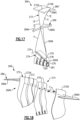
- FIGS 17 and 18 illustrate an airfoil 266 according to yet another example.
- Airfoil 266 includes at least one shroud 286 that extends outwardly from pressure and suction sides P, S of airfoil section 266A at a position radially outward of platforms 270 (shown in dashed lines in Figure 17 for illustrative purposes).
- the shroud 286 defines an external surface contour and can be utilized to tune mode(s) of the airfoil 266 by changing boundary constraints.
- the shroud 286 can be made of a composite or metallic material, including any of the materials disclosed herein, or can be made of an injection molded plastic having a plastic core and a thin metallic coating, for example.
- the airfoil 266 can include a second shroud 286' (shown in dashed lines) to provide a dual shroud architecture, with shroud 286 arranged to divide airfoil between bypass and core flow paths B, C ( Figure 1 ) and shroud 286' for reducing a flutter condition of the airfoil 266, for example.
- a second shroud 286' shown in dashed lines to provide a dual shroud architecture, with shroud 286 arranged to divide airfoil between bypass and core flow paths B, C ( Figure 1 ) and shroud 286' for reducing a flutter condition of the airfoil 266, for example.
- the shroud 286 includes first and second shroud portions 286A, 286B secured to the opposing pressure and suction sides P, S.
- the shroud portions 286A, 286B can be joined together with one or more inserts fasteners F that extend through the airfoil section 266A.
- the fasteners F can be baked into the ligaments 276, for example, and can be frangible to release in response to a load on either of the shroud portions 286A, 286B exceeding a predefined threshold.
- the airfoil 266 includes only one of the shroud portions 286A, 286B such that the shroud 286 is on only one side of the airfoil section 266A or is otherwise unsymmetrical.
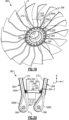
- FIG 19 illustrates a rotor assembly 360 according to another example.
- the rotor assembly 360 includes an array of platforms 370 that are releasably secured to hub 362.
- the platforms 370 are separate and distinct from the airfoils 366.
- Each platform 370 includes one or more features that support the adjacent airfoils 366 to oppose circumferential or other relative movement during engine operation.
- each platform 370 includes a platform body 388 that extends in a circumferential or thickness direction T between first and second sidewalls 390 to define an aerodynamic contour or gas path surface 391.
- the platform body 388 includes at least one bracket or flange 392 that is mechanically attachable or otherwise secured to the platform body 388.
- each of the flanges 392 is integrally formed with the platform body 388.
- the flanges 392 are mechanically attachable to respective flanges 362B ( Figure 21 ) to mechanically attach or otherwise secure the platform 370 to the hub 362.
- Each airfoil section 366A may be pivotable about a respective retention pin 368 in an installed position, which may cause the airfoil 366 to pivot or lean in the circumferential direction T, for example.
- the platform 370 includes a plurality of resilient support members 394 that each extend from the platform body 388 and are dimensioned to abut against a sheath 372 of an adjacent airfoil 366 to oppose movement of the airfoil section 366A in the circumferential direction T, for example.
- Each of the support members 394 can be dimensioned to abut against the sheath 372 at a position that is radially outward of the retention pins 368.
- the support members 394 are arranged in opposed rows of support members 394-1, 394-2.
- the rows of support members 394-1, 394-2 are dimensioned to provide a spring bias or force against the airfoils 366, wedge the platform 370 between adjacent airfoils 366, and oppose circumferential movement of the adjacent airfoils 366 relative to the longitudinal axis X.
- each of the support members 394 can be a retention tab including a retention body having first and second portions 394A, 394B.
- the first portion 394A can extend in the circumferential direction T outwardly from the platform body 388, and the second portion 388B can be flared or otherwise extend in a radial direction R from the first portion 394A and outwardly with respect to the platform body 388 to mate with a contour of the airfoil section 366A of the adjacent airfoil 366.
- the platform body 388 can define a plurality of slots or cutouts 396 along the sidewalls 390 to define and space apart the support members 394.
- the platform 370 can be made of a metallic material such as aluminum or sheet metal, or can be made of a composite material.
- the support members 394 can be integrally formed with the platform body 388 such that the support members 394 are resilient and ductile or otherwise flexible. In other examples, the support members 394 are mechanically attached to the platform body 388 utilizing various techniques such as by bonding, welding, or riveting.
- the platform 370 supports adjacent airfoils 366 against gas loads during engine operation.
- the support members 394 are constructed to be relatively strong and ductile to support the adjacent airfoils 366 during normal operation and to transfer loads in a manner that reduces a likelihood of permanent deformation, liberation or other degradation of the platforms 370 and airfoils 366.
- the retention pins 368 can reduce a bending stiffness of the airfoils 366 due the ability of the airfoils 366 to pivot about the retention pins 368.
- the support members 394 can be constructed to have different stiffnesses utilizing the techniques disclosed herein, including being relatively stiff and elastic for a flutter mode, but yielding during relatively more severe bending or leaning of the airfoil 366.
- each airfoil 366 may be subject to an internal and/or external load or force F, such as flutter, vibratory or centrifugal loads, or impacts caused by bird strikes or other FOD events.
- the force F may cause or urge the airfoil to lean or pivot about a respective one of the retention pins 368 ( Figures 20-22 ).
- the platforms 370 including support members 394 serve to support and hold the adjacent airfoils 366 in a predefined aerodynamic position to increase aerodynamic performance and support the airfoils 366 during impact events.
- Each one of the support members 394 can be dimensioned to oppose circumferential movement of the adjacent airfoil 366 in response to the force or load F on the airfoil 366 being below a predefined limit, but can be dimensioned to deflect or yield in response to the load or force F exceeding the predefined limit as illustrated by support member 394' and airfoil 366' (shown in dashed lines for illustrative purposes). Yielding of the support members 394 reduces a likelihood that the platform 370 will liberate or otherwise degrade due to high energy impacts such as bird strikes.
- each support member 394 can be dimensioned to have an L-shaped geometry that reacts the load or force F on a respective one of the airfoils 366 in operation.
- the support members 394 serve to cushion the airfoils 366 from the force F, which can improve durability and propulsive efficiency of the airfoils 366.
- the rotor assembly 360 can be installed as follows. Flanges 392 are mounted or otherwise secured to the platform body 388, as illustrated by Figure 24 . Thereafter, the platform 370 can be moved in direction D1 to wedge the platform 370 between adjacent platforms 366, as illustrated by Figure 21 . Thereafter, one or more fasteners 398, such as elongated bolts or pins, can be moved in direction D2 to secure the flanges 392 to respective annular flanges 362B of the hub 362. The fasteners 398 are illustrated in an installed position in Figures 21 and 22 .
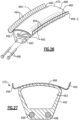
- FIGs 26 and 27 illustrate a platform 470 for a rotor assembly according to another example.
- the platform 470 includes an elongated flange 492 mechanically attached or otherwise secured to platform body 488.
- a plurality of support members 494 extend outwardly from the platform body 488 to abut against and support adjacent airfoils.
- the flange 492 extends along a length of platform body 488.
- the flange 492 can have a hollow interior 493 that extends between opposed ends of the flange 492.
- the flange 492 defines one or more slots 495 ( Figure 26 ) to receive a respective flange of the hub (see, e.g., flanges 362B of Figure 25 ).
- a cross-section of the flange 492 can have a generally trapezoidal geometry, as illustrated by Figure 27 , or another geometry such as a triangular or rectangular profile.
- the flange 492 defines apertures for receiving fasteners 498 to mechanically attach the platform 470 to a hub, such as hub 362 of Figure 25 .
Abstract
Description
- This disclosure relates to a gas turbine engine, and more particularly to a rotor assembly including a hub that carries an array of airfoils.
- Gas turbine engines can include a fan for propulsion air and to cool components. The fan also delivers air into a core engine where it is compressed. The compressed air is then delivered into a combustion section, where it is mixed with fuel and ignited. The combustion gas expands downstream over and drives turbine blades. Static vanes are positioned adjacent to the turbine blades to control the flow of the products of combustion. The fan typically includes an array of fan blades having dovetails that are mounted in slots of a fan hub.
- A platform for a gas turbine engine according to an aspect of the present disclosure includes a platform body that extends in a circumferential direction between first and second sidewalls to define a gas path surface, and opposed rows of flexible retention tabs that extend from the platform body and are dimensioned to wedge the platform between adjacent airfoils.
- In a further embodiment of any of the foregoing embodiments, the platform body defines a plurality of slots that space apart the retention tabs.
- In a further embodiment of any of the foregoing embodiments, each of the retention tabs includes a first portion that extends in the circumferential direction and a second portion that extends in a radial direction from the first portion to mate with a contour of a respective one of the adjacent airfoils.
- In a further embodiment of any of the foregoing embodiments, each of the retention tabs is integrally formed with the platform body, and the platform body is made of a metallic material.
- In a further embodiment of any of the foregoing embodiments, the platform body includes at least one flange attachable to a rotatable hub.
- A rotor assembly for a gas turbine engine according to another aspect of the present disclosure includes a rotatable hub that has a main body that extends along a longitudinal axis, and that has an array of annular flanges that extend about an outer periphery of the main body to define an array of annular channels along the longitudinal axis. An array of airfoils are circumferentially distributed about the outer periphery. Each one of the airfoils has an airfoil section that extends from a root section received in the annular channels. The airfoil section extends between a leading edge and a trailing edge in a chordwise direction and extends between a tip portion and the root section in a radial direction, and the airfoil section defines a pressure side and a suction side separated in a thickness direction. An array of platforms are releasably secured to the hub. Each of the platforms includes a platform body and opposed rows of resilient support members that abut against adjacent airfoils of the array of airfoils to oppose movement of the respective airfoil section in the circumferential direction.
- A further embodiment of any of the foregoing embodiments includes a plurality of retention pins each extending through the root section of a respective one of the airfoils and through each of the annular flanges to mechanically attach the root section to the hub.
- In a further embodiment of any of the foregoing embodiments, the airfoil section is pivotable about a respective one of the retention pins in an installed position.
- In a further embodiment of any of the foregoing embodiments, the platform body is mechanically attached to the hub. The airfoil section includes a metallic sheath that receives a composite core, and the core includes first and second ligaments received in respective internal channels defined by the sheath such that the first and second ligaments are spaced apart along the root section with respect to the longitudinal axis.
- In a further embodiment of any of the foregoing embodiments, each of the support members is a retention tab that abuts against the sheath of a respective one of the adjacent airfoils.
- In a further embodiment of any of the foregoing embodiments, the retention tab opposes circumferential movement of the respective one of the adjacent airfoils in response to a load on the respective one of the adjacent airfoils being below a predefined limit, but deflects in response to the load exceeding the predefined limit.
- A further embodiment of any of the foregoing embodiments includes a plurality of retention pins each extending through the root section of a respective one of the airfoils and through each of the annular flanges to mechanically attach the root section to the hub, and wherein the airfoil section is pivotable about a respective one of the retention pins in an installed position.
- In a further embodiment of any of the foregoing embodiments, the retention tab abuts against the sheath of the respective one of the adjacent airfoils at a position radially outward of the retention pins.
- In a further embodiment of any of the foregoing embodiments, the first and second ligaments define a set of bores aligned to receive a common one of the retention pins.
- In a further embodiment of any of the foregoing embodiments, the opposed rows of support members extend outwardly from the platform body and are dimensioned to wedge the platform between the adjacent airfoils.
- In a further embodiment of any of the foregoing embodiments, each of the support members is a retention tab that abuts against the sheath of a respective one of the adjacent airfoils. The retention tab includes a retention body that has an L-shaped geometry that reacts a load on a respective one of the adjacent airfoils in operation, and the retention body is integrally formed with the platform body.
- A gas turbine engine according to another aspect of the present disclosure includes a fan section that has a fan shaft rotatable about an engine longitudinal axis. The fan section has a rotor assembly. The rotor assembly includes a rotatable hub that has a main body mechanically attached to the fan shaft, and has an array of annular flanges that extend about an outer periphery of the main body to define an array of annular channels along the engine longitudinal axis. An array of airfoils are circumferentially distributed about the outer periphery. Each one of the airfoils includes an airfoil section that extends from a root section received in the annular channels. An array of platforms are releasably secured to the hub. Each of the platforms includes a platform body and opposed rows of flexible support members that extend from the platform body and are dimensioned to wedge the platform between adjacent airfoils and oppose circumferential movement of the adjacent airfoils relative to the engine longitudinal axis.
- In a further embodiment of any of the foregoing embodiments, the airfoil section includes a metallic sheath and a composite core. The core includes first and second ligaments at least partially received in respective internal channels defined in the sheath.
- A further embodiment of any of the foregoing embodiments includes a plurality of retention pins, each of the retention pins extending through the root section of a respective one of the airfoils, across the annular channels, and through the annular flanges to mechanically attach the root section to the hub.
- In a further embodiment of any of the foregoing embodiments, the airfoil section is pivotable about a respective one of the retention pins in an installed position. Each of the support members is an L-shaped retention tab integrally formed with the platform body. The platform body is made of a metallic material, and the retention tab opposes circumferential movement of the respective one of the adjacent airfoils in response to a load on the respective one of the adjacent airfoils being below a predefined limit, but deflects in response to the load exceeding the predefined limit.
- The various features and advantages of this disclosure will become apparent to those skilled in the art from the following detailed description. The drawings that accompany the detailed description can be briefly described as follows.
-
-
Figure 1 illustrates an example turbine engine. -
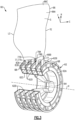
Figure 2 illustrates a perspective view of an example rotor assembly including an array of airfoils. -
Figure 3 illustrates a perspective view of one of the airfoils ofFigure 2 secured to a hub. -
Figure 4 illustrates adjacent airfoils of the rotor assembly ofFigure 2 . -
Figure 5A illustrates an exploded view of portions of the rotor assembly ofFigure 2 . -
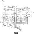
Figure 5B illustrates a side view of the rotor assembly ofFigure 2 with the hub illustrated in cross-section. -
Figure 6 illustrates an end view of an airfoil section of one of the airfoils ofFigure 2 . -
Figure 7 illustrates an exploded view of the airfoil section ofFigure 6 . -
Figure 8 illustrates an exploded perspective view of an airfoil including the airfoil section ofFigure 6 . -
Figure 9 illustrates a sectional view of a composite core. -
Figure 10 illustrates a sectional view of the composite core ofFigure 9 secured to a sheath. -
Figure 11 illustrates an interface portion of the composite core ofFigure 9 . -
Figure 12 illustrates the composite core arranged relative to skins of the sheath ofFigure 10 . -
Figure 13 illustrates a sectional view of the airfoil ofFigure 10 . -
Figure 14A illustrates a three-dimensional woven fabric for a composite layer. -
Figure 14B illustrates a plurality of braided yarns for a composite layer. -
Figure 14C illustrates a two-dimensional woven fabric for a composite layer. -
Figure 14D illustrates a non-crimp fabric for a composite layer. -
Figure 14E illustrates a tri-axial braided fabric for a composite layer. -
Figure 15 illustrates an exploded view of an airfoil including a sheath and core according to another example. -
Figure 16 illustrates the core situated in the sheath ofFigure 15 . -
Figure 17 illustrates an airfoil including a shroud according to yet another example. -
Figure 18 illustrates an exploded view of the airfoil ofFigure 17 . -
Figure 19 illustrates a perspective view of a rotor assembly according to another example. -
Figure 20 illustrates an axial view of a platform and adjacent airfoils of the rotor assembly ofFigure 19 . -
Figure 21 illustrates a perspective view selected portions of the rotor assembly including the platform ofFigure 20 . -
Figure 22 illustrates a perspective view of selected portions of the rotor assembly ofFigure 21 . -
Figure 23 illustrates an axial view of the platform ofFigure 20 relative to different positions of an adjacent airfoil. -
Figure 24 illustrates another perspective view of the platform ofFigure 20 . -
Figure 25 illustrates an exploded view of the rotor assembly ofFigure 21 . -
Figure 26 illustrates a perspective view of a platform for a rotor assembly according to another example. -
Figure 27 illustrates a sectional view of the platform ofFigure 26 . -
Figure 1 schematically illustrates agas turbine engine 20. Thegas turbine engine 20 is disclosed herein as a two-spool turbofan that generally incorporates afan section 22, acompressor section 24, a combustor section 26 and aturbine section 28. Thefan section 22 drives air along a bypass flow path B in a bypass duct defined within anacelle 15, and also drives air along a core flow path C for compression and communication into the combustor section 26 then expansion through theturbine section 28. Although depicted as a two-spool turbofan gas turbine engine in the disclosed non-limiting embodiment, it should be understood that the concepts described herein are not limited to use with two-spool turbofans as the teachings may be applied to other types of turbine engines including three-spool architectures. - The
exemplary engine 20 generally includes alow speed spool 30 and ahigh speed spool 32 mounted for rotation about an engine central longitudinal axis A relative to an enginestatic structure 36 viaseveral bearing systems 38. It should be understood that various bearingsystems 38 at various locations may alternatively or additionally be provided, and the location of bearingsystems 38 may be varied as appropriate to the application. - The
low speed spool 30 generally includes aninner shaft 40 that interconnects, a first (or low)pressure compressor 44 and a first (or low)pressure turbine 46. Theinner shaft 40 is connected to thefan 42 through a speed change mechanism, which in exemplarygas turbine engine 20 is illustrated as a gearedarchitecture 48 to drive afan 42 at a lower speed than thelow speed spool 30. Thehigh speed spool 32 includes anouter shaft 50 that interconnects a second (or high)pressure compressor 52 and a second (or high)pressure turbine 54. Acombustor 56 is arranged inexemplary gas turbine 20 between thehigh pressure compressor 52 and thehigh pressure turbine 54. Amid-turbine frame 57 of the enginestatic structure 36 may be arranged generally between thehigh pressure turbine 54 and thelow pressure turbine 46. Themid-turbine frame 57 furthersupports bearing systems 38 in theturbine section 28. Theinner shaft 40 and theouter shaft 50 are concentric and rotate via bearingsystems 38 about the engine central longitudinal axis A which is collinear with their longitudinal axes. - The core airflow is compressed by the
low pressure compressor 44 then thehigh pressure compressor 52, mixed and burned with fuel in thecombustor 56, then expanded over thehigh pressure turbine 54 andlow pressure turbine 46. Themid-turbine frame 57 includesairfoils 59 which are in the core airflow path C. Theturbines low speed spool 30 andhigh speed spool 32 in response to the expansion. It will be appreciated that each of the positions of thefan section 22,compressor section 24, combustor section 26,turbine section 28, and fandrive gear system 48 may be varied. For example,gear system 48 may be located aft of the low pressure compressor, or aft of the combustor section 26 or even aft ofturbine section 28, andfan 42 may be positioned forward or aft of the location ofgear system 48. - The
engine 20 in one example is a high-bypass geared aircraft engine. In a further example, theengine 20 bypass ratio is greater than about six, with an example embodiment being greater than about ten, the gearedarchitecture 48 is an epicyclic gear train, such as a planetary gear system or other gear system, with a gear reduction ratio of greater than about 2.3 and thelow pressure turbine 46 has a pressure ratio that is greater than about five. In one disclosed embodiment, theengine 20 bypass ratio is greater than about ten, the fan diameter is significantly larger than that of thelow pressure compressor 44, and thelow pressure turbine 46 has a pressure ratio that is greater than about five.Low pressure turbine 46 pressure ratio is pressure measured prior to inlet oflow pressure turbine 46 as related to the pressure at the outlet of thelow pressure turbine 46 prior to an exhaust nozzle. The gearedarchitecture 48 may be an epicycle gear train, such as a planetary gear system or other gear system, with a gear reduction ratio of greater than about 2.3:1 and less than about 5:1. It should be understood, however, that the above parameters are only exemplary of one embodiment of a geared architecture engine and that the present invention is applicable to other gas turbine engines including direct drive turbofans. - A significant amount of thrust is provided by the bypass flow B due to the high bypass ratio. The
fan section 22 of theengine 20 is designed for a particular flight condition -- typically cruise at about 0.8 Mach and about 35,000 feet (10,668 meters). The flight condition of 0.8 Mach and 35,000 ft (10,668 meters), with the engine at its best fuel consumption - also known as "bucket cruise Thrust Specific Fuel Consumption ('TSFC')" - is the industry standard parameter of lbm of fuel being burned divided by lbf of thrust the engine produces at that minimum point. "Low fan pressure ratio" is the pressure ratio across the fan blade alone, without a Fan Exit Guide Vane ("FEGV") system. The low fan pressure ratio as disclosed herein according to one non-limiting embodiment is less than about 1.45. "Low corrected fan tip speed" is the actual fan tip speed in ft/sec divided by an industry standard temperature correction of [(Tram °R) / (518.7 °R)]0.5 (where °R = K x 9/5). The "Low corrected fan tip speed" as disclosed herein according to one non-limiting embodiment is less than about 1150 ft / second (350.5 meters/second). -
Figure 2 illustrates arotor assembly 60 for a gas turbine engine according to an example. Therotor assembly 60 can be incorporated into thefan section 22 or thecompressor section 24 of theengine 20 ofFigure 1 , for example. However, it should to be understood that other parts of thegas turbine engine 20 and other systems may benefit from the teachings disclosed herein. In some examples, therotor assembly 60 is incorporated into a multi-stage fan section of a direct drive or geared engine architecture. - The
rotor assembly 60 includes arotatable hub 62 mechanically attached or otherwise mounted to afan shaft 64. Thefan shaft 64 is rotatable about longitudinal axis X. Thefan shaft 64 can be rotatably coupled to the low pressure turbine 46 (Figure 1 ), for example. Therotatable hub 62 includes amain body 62A that extends along the longitudinal axis X. The longitudinal axis X can be parallel to or collinearly with the engine longitudinal axis A ofFigure 1 , for example. As illustrated byFigure 3 , thehub 62 includes an array ofannular flanges 62B that extend about anouter periphery 62C of themain body 62A. Theannular flanges 62B define an array ofannular channels 62D along the longitudinal axis X. - An array of
airfoils 66 are circumferentially distributed about theouter periphery 62C of therotatable hub 62. Referring toFigure 3 , with continued reference toFigure 2 , one of theairfoils 66 mounted to thehub 62 is shown for illustrative purposes. Theairfoil 66 includes anairfoil section 66A extending from aroot section 66B. Theairfoil section 66A extends between a leading edge LE and a trailing edge TE in a chordwise direction C, and extends in a radial direction R between theroot section 66B and atip portion 66C to provide an aerodynamic surface. Thetip portion 66C defines a terminal end or radially outermost extent of theairfoil 66 to establish a clearance gap with fan case 15 (Figure 1 ). Theairfoil section 66A defines a pressure side P (Figure 2 ) and a suction side S separated in a thickness direction T. Theroot section 66B is dimensioned to be received in each of theannular channels 62D. - The
rotor assembly 60 includes an array ofplatforms 70 that are separate and distinct from theairfoils 66. Theplatforms 70 are situated between and abut against adjacent pairs ofairfoils 66 to define an inner boundary of a gas path along therotor assembly 60, as illustrated inFigure 2 . Theplatforms 70 can be mechanically attached and releasably secured to thehub 62 with one or more fasteners, for example.Figure 4 illustrates one of theplatforms 70 abutting against theairfoil section 66A of adj acentairfoils 66. -
Figure 5A illustrates an exploded, cutaway view of portions of therotor assembly 60.Figure 5B illustrates a side view of one of theairfoils 66 secured to thehub 62. Therotor assembly 60 includes a plurality of retention pins 68 for securing theairfoils 66 to the hub 62 (seeFigure 2 ). Each of theplatforms 70 can abut theadjacent airfoils 66 at a position radially outward of the retention pins 68, as illustrated byFigure 2 . - Each of the retention pins 68 is dimensioned to extend through the
root section 66B of a respective one of theairfoils 66 and to extend through each of theflanges 62B to mechanically attach theroot section 66B of therespective airfoil 66 to thehub 62, as illustrated byFigures 3 and5B . The retention pins 68 react to centrifugal loads in response to rotation of theairfoils 66. Thehub 62 can include at least threeannular flanges 62B, such as fiveflanges 62B as shown, that are axially spaced apart relative to the longitudinal axis X to support a length of each of the retention pins 68. However, fewer or more than fiveflanges 62B can be utilized with the teachings herein. Utilizing three ormore flanges 62B can provide relatively greater surface contact area and support along a length eachretention pin 68, which can reduce bending and improve durability of theretention pin 68. - The
airfoil 66 can be a hybrid airfoil including metallic and composite portions. Referring toFigures 6-8 , with continuing reference toFigures 5A-5B , theairfoil 66 includes ametallic sheath 72 that at least partially receives and protects acomposite core 74. In some examples, substantially all of the aerodynamic surfaces of theairfoil 66 are defined by thesheath 72. Thesheath 72 can be dimensioned to terminate radially inward prior to theroot section 66B such that thesheath 72 is spaced apart from the respective retention pin(s) 68, as illustrated byFigure 5B . Thesheath 72 includes afirst skin 72A and asecond skin 72B. The first andsecond skins airfoil 66 including the pressure and suction sides P, S of theairfoil section 66A. - The
core 74 includes one ormore ligaments 76 that define portions of the airfoil androot sections ligament 76 can define radially outermost extent or tip of thetip portion 66C, as illustrated byFigure 6 . In other examples, theligaments 76 terminate prior to the tip of theairfoil section 66A. In the illustrative example ofFigures 6-8 , thecore 74 includes two separate anddistinct ligaments Figures 5B and6 . The core 74 can include fewer or more than twoligaments 76, such as three to tenligaments 76. Theligaments root section 66B towards thetip portion 66C of theairfoil section 66A, as illustrated byFigures 3 ,6 and 8 . - The
sheath 72 defines one or moreinternal channels core 74. In the illustrated example ofFigures 6-8 , thesheath 72 includes at least onerib 73 defined by thefirst skin 72A that extends in the radial direction R to bound theadjacent channels ligaments internal channels skins core 74 and sandwich theligaments Figure 6 . Theligaments common retention pin 68 such that thecommon retention pin 68 is slideably received through at least three, or each, ofannular flanges 62B. Thecommon retention pin 68 is dimensioned to extend through each and every one of theinterface portions 78 of therespective airfoil 66 to mechanically attach or otherwise secure theairfoil 66 to thehub 62. - Referring to
Figures 9-10 , with continued reference toFigures 5A-5B and6-8 , each of one of theligaments 76 includes at least oneinterface portion 78 in theroot section 66B.Figure 9 illustratesligament 76 with the first andsecond skin Figure 10 illustrates thecore 74 andskins interface portion 78 defining portions of theroot section 66B. Theinterface portion 78 includes a wrappingmandrel 79 and abushing 81 mechanically attached to themandrel 79 with an adhesive, for example. Thebushing 81 is dimensioned to slideably receive one of the retention pins 68 (Figure 5B ). Themandrel 79 tapers from thebushing 81 to define a teardrop profile, as illustrated byFigure 11 . - In the illustrative example of
Figures 5B and8 , each of theligaments 76 defines at least oneslot 77 in theroot section 66B to define first andsecond root portions annular channels 62D on opposed sides of therespective flange 62B such that theroot portions flanges 62B. Theslots 77 can decrease bending of the retention pins 68 by decreasing a distance betweenadjacent flanges 62B and increase contact area and support along a length of theretention pin 68, which can reduce contact stresses and wear. - Each
ligament 76 can include a plurality of interface portions 78 (indicated as 78A, 78B) received inroot portions interface portions ligament common retention pin 68 to mechanically attach or otherwise secure theligaments hub 62. Theroot section 66B defines at least one bore 85 dimensioned to receive aretention pin 68. In the illustrated example ofFigure 5B , each bore 85 is defined by arespective bushing 81. - Various materials can be utilized for the
sheath 72 andcomposite core 74. In some examples, the first andsecond skins core 74 comprises carbon or carbon fibers, such as a ceramic matrix composite (CMC). In examples, thesheath 72 defines a first weight, thecomposite core 74 defines a second weight, and a ratio of the first weight to the second weight is at least 1:1 such that at least 50% of the weight of theairfoil 66 is made of a metallic material. The metal or metal alloy can provide relatively greater strength and durability under operating conditions of the engine and can provide relatively greater impact resistance to reduce damage from foreign object debris (FOD). The composite material can be relatively strong and lightweight, but may not be as ductile as metallic materials, for example. The hybrid construction ofairfoils 66 can reduce an overall weight of therotor assembly 60. - In the illustrative example of
Figures 9 and 10 , each of theligaments 76 includes at least onecomposite layer 80. Eachcomposite layer 80 can be fabricated to loop around theinterface portion 78 and retention pin 68 (when in an installed position) such thatopposed end portions respective layer 80 are joined together along theairfoil portion 66A. The composite layers 80 can be dimensioned to define a substantiallysolid core 74, such that substantially all of a volume of theinternal cavities sheath 72 are occupied by a composite material comprising carbon. In the illustrated example ofFigures 9 and 10 , thecomposite layers 80 include a firstcomposite layer 80C and a secondcomposite layer 80D between thefirst layer 80C and an outer periphery of theinterface portion 78. Thecomposite layers interface portion 78 and theretention pin 68. - The
layers 80 can include various fiber constructions to define thecore 74. For example, thefirst layer 80C can define a first fiber construction, and thesecond layer 80D can define a second fiber construction that differs from the first fiber construction. The first fiber construction can include one or more uni-tape plies or a fabric, and the second fiber construction can include at least one ply of a three-dimensional weave of fibers as illustrated by layer 80-1 ofFigure 14A , for example. It should be appreciated that uni-tape plies include a plurality of fibers oriented in the same direction ("uni-directional), and fabric includes woven or interlaced fibers, each known in the art. In examples, each of the first and second fiber constructions includes a plurality of carbon fibers. However, other materials can be utilized for each of the fiber constructions, including fiberglass, Kevlar®, a ceramic such as Nextel™, a polyethylene such as Spectra®, and/or a combination of fibers. - Other fiber constructions can be utilized to construct each of the
layers 80, including any of the layers 80-2 to 80-5 ofFigures 14B-14E. Figure 14B illustrates a layer 80-2 defined by a plurality of braided yarns.Figure 14C illustrates a layer 80-3 defined by a two-dimensional woven fabric.Figure 14D illustrates a layer 80-4 defined by a non-crimp fabric.Figure 14E illustrates a layer 80-5 defined by a tri-axial braided fabric. Other example fiber constructions include biaxial braids and plain or satin weaves. - The
rotor assembly 60 can be constructed and assembled as follows. Theligaments core 74 are situated in the respectiveinternal channels sheath 72 such that theligaments root section 66B by one of theannular flanges 62B and abut against opposed sides ofrib 73, as illustrated byFigures 5B ,6 and13 . - In some examples, the
ligaments internal channels ligaments 76 are moveable relative to surfaces of theinternal channels Figures 9-10 and 12-13 , thecore 74 includes a plurality of stand-offs ordetents 82 that are distributed along surfaces of theligaments 76. Thedetents 82 are dimensioned and arranged to space apart theligaments 76 from adjacent surfaces of theinternal channels detents 82 can include conical, hemispherical, pyramidal and complex geometries. Thedetents 82 can be uniformly or nonuniformly distributed. Thedetents 82 can be formed from a fiberglass fabric or scrim having raised protrusions made of rubber or resin that can be fully cured or co-cured with theligaments 76, for example. - The
second skin 72B is placed against thefirst skin 72A to define an external surface contour of theairfoil 66, as illustrated byFigures 6 and13 . Theskins ligaments 76. - The
detents 82 can define relatively large bondline gaps between theligaments 76 and the surfaces of theinternal channels sheath 72 to theligaments 76. The relatively large bondline gaps established by thedetents 82 can improve flow of resin or adhesive such as polyurethane and reducing formation of dry areas. In examples, thedetents 82 are dimensioned to establish bondline gap of at least a 0.020 inches (0.508 mm), or more narrowly between 0.020 and 0.120 inches (0.508 and 3.048 mm). The relatively large bondline gap can accommodate manufacturing tolerances between thesheath 72 andcore 74, can ensure proper positioning during final cure and can ensure proper bond thickness. The relatively large bondline gap allows the metal and composite materials to thermally expand, which can reduce a likelihood of generating discontinuity stresses. The gaps anddetents 82 can also protect the composite from thermal degradation during welding or brazing of theskins - For example, a resin or adhesive such as polyurethane can be injected into gaps or spaces established by the
detents 82 between theligaments 76 and the surfaces of theinternal channels metallic sheath 72 andcomposite core 74, provide structural damping, isolate the delicate inner fibers of thecomposite core 74 from relatively extreme welding temperatures during attachment of thesecond skin 72B to thefirst skin 72A, and enables theductile sheath 72 to yield during a bird strike or other FOD event, which can reduce a likelihood of degradation of the relatively brittle inner fibers of thecomposite core 74. - The composite layers 80 can be simultaneously cured and bonded to each other with the injected resin, which may be referred to as "co-bonding" or "cocuring". In other examples, the
composite layers 80 can be pre-formed or preimpregnated with resin prior to placement in theinternal channels composite core 74 is cured in an oven, autoclave or by other conventional methods, with theligaments 76 bonded to thesheath 72, as illustrated byFigures 10 and 13 . - The
airfoils 66 are moved in a direction D1 (Figures 5A-5B ) toward theouter periphery 62C of thehub 62. Arespective retention pin 68 is slideably received through eachbushing 81 of theinterface portions 78 and each of theflanges 62B to mechanically attach theligaments 76 to theflanges 62B. Theplatforms 70 are then moved into abutment against respective pairs ofairfoils 66 at a position radially outward of theflanges 62B to limit circumferential movement of theairfoil sections 66A, as illustrated byFigure 2 . - Mechanically attaching the
airfoils 66 withretention pins 68 can allow theairfoil 66 to flex and twist, which can reduce a likelihood of damage caused by FOD impacts by allowing theairfoil 66 to bend away from the impacts. Therotor assembly 60 also enables relatively thinner airfoils which can improve aerodynamic efficiency. -
Figures 15-16 illustrate anairfoil 166 according to another example. In this disclosure, like reference numerals designate like elements where appropriate and reference numerals with the addition of one-hundred or multiples thereof designate modified elements that are understood to incorporate the same features and benefits of the corresponding original elements. Afirst skin 172A ofsheath 172 definesinternal channels internal channels ribs 173. Theribs 173 can extend in a radial direction R, for example, and are spaced apart along aninternal gap 172F that interconnects theinternal cavities internal gap 172F can be spaced apart from the radial innermost and outermost ends of thefirst skin 172A of thesheath 172.Composite core 174 includes aligament bridge 184 that interconnects an adjacent pair ofligaments 176 at a location radially outward of a common pin 168 (shown in dashed lines inFigure 15 for illustrative purposes). Theligament bridge 184 can be made of any of the materials disclosed herein, such as a composite material. - The
ligament bridge 184 is dimensioned to be received within thegap 172F. Theligament bridge 184 interconnects the adjacent pair ofligaments 176 in a position along theairfoil section 166A when in the installed position. During operation, thecore 174 may move in a direction D2 (Figure 16 ) relative to thesheath 172, which can correspond to the radial direction R, for example. Theligament bridge 184 is dimensioned to abut against the opposingribs 173 of thesheath 172 in response to movement in direction D2 to react blade pull and bound radial movement of thecore 174 relative to thesheath 172. Theligament bridge 184 serves as a failsafe by trapping theligaments 176 to reduce a likelihood of liberation of theligaments 176 which may otherwise occur due to failure of the bond between thesheath 172 andligaments 176. -
Figures 17 and 18 illustrate anairfoil 266 according to yet another example.Airfoil 266 includes at least oneshroud 286 that extends outwardly from pressure and suction sides P, S ofairfoil section 266A at a position radially outward of platforms 270 (shown in dashed lines inFigure 17 for illustrative purposes). Theshroud 286 defines an external surface contour and can be utilized to tune mode(s) of theairfoil 266 by changing boundary constraints. Theshroud 286 can be made of a composite or metallic material, including any of the materials disclosed herein, or can be made of an injection molded plastic having a plastic core and a thin metallic coating, for example. Theairfoil 266 can include a second shroud 286' (shown in dashed lines) to provide a dual shroud architecture, withshroud 286 arranged to divide airfoil between bypass and core flow paths B, C (Figure 1 ) and shroud 286' for reducing a flutter condition of theairfoil 266, for example. - The
shroud 286 includes first andsecond shroud portions shroud portions airfoil section 266A. The fasteners F can be baked into theligaments 276, for example, and can be frangible to release in response to a load on either of theshroud portions shroud portions airfoil 266, such as by an adhesive, welding or integrally forming theskins respective shroud portions airfoil 266 includes only one of theshroud portions shroud 286 is on only one side of theairfoil section 266A or is otherwise unsymmetrical. -
Figure 19 illustrates arotor assembly 360 according to another example. Therotor assembly 360 includes an array ofplatforms 370 that are releasably secured tohub 362. Theplatforms 370 are separate and distinct from theairfoils 366. Eachplatform 370 includes one or more features that support theadjacent airfoils 366 to oppose circumferential or other relative movement during engine operation. - Referring to
Figure 20 , with continued reference toFigure 19 , eachplatform 370 includes aplatform body 388 that extends in a circumferential or thickness direction T between first andsecond sidewalls 390 to define an aerodynamic contour orgas path surface 391. Theplatform body 388 includes at least one bracket orflange 392 that is mechanically attachable or otherwise secured to theplatform body 388. In other examples, each of theflanges 392 is integrally formed with theplatform body 388. Theflanges 392 are mechanically attachable torespective flanges 362B (Figure 21 ) to mechanically attach or otherwise secure theplatform 370 to thehub 362. Eachairfoil section 366A may be pivotable about arespective retention pin 368 in an installed position, which may cause theairfoil 366 to pivot or lean in the circumferential direction T, for example. - The
platform 370 includes a plurality ofresilient support members 394 that each extend from theplatform body 388 and are dimensioned to abut against asheath 372 of anadjacent airfoil 366 to oppose movement of theairfoil section 366A in the circumferential direction T, for example. Each of thesupport members 394 can be dimensioned to abut against thesheath 372 at a position that is radially outward of the retention pins 368. - In the illustrated example of
Figure 20 , thesupport members 394 are arranged in opposed rows of support members 394-1, 394-2. The rows of support members 394-1, 394-2 are dimensioned to provide a spring bias or force against theairfoils 366, wedge theplatform 370 betweenadjacent airfoils 366, and oppose circumferential movement of theadjacent airfoils 366 relative to the longitudinal axis X. - Referring to
Figures 21 and 22 , with continued reference toFigures 19 and 20 , each of thesupport members 394 can be a retention tab including a retention body having first andsecond portions first portion 394A can extend in the circumferential direction T outwardly from theplatform body 388, and the second portion 388B can be flared or otherwise extend in a radial direction R from thefirst portion 394A and outwardly with respect to theplatform body 388 to mate with a contour of theairfoil section 366A of theadjacent airfoil 366. Theplatform body 388 can define a plurality of slots orcutouts 396 along thesidewalls 390 to define and space apart thesupport members 394. Theplatform 370 can be made of a metallic material such as aluminum or sheet metal, or can be made of a composite material. Thesupport members 394 can be integrally formed with theplatform body 388 such that thesupport members 394 are resilient and ductile or otherwise flexible. In other examples, thesupport members 394 are mechanically attached to theplatform body 388 utilizing various techniques such as by bonding, welding, or riveting. - The
platform 370 supportsadjacent airfoils 366 against gas loads during engine operation. Thesupport members 394 are constructed to be relatively strong and ductile to support theadjacent airfoils 366 during normal operation and to transfer loads in a manner that reduces a likelihood of permanent deformation, liberation or other degradation of theplatforms 370 andairfoils 366. For example, the retention pins 368 can reduce a bending stiffness of theairfoils 366 due the ability of theairfoils 366 to pivot about the retention pins 368. Thesupport members 394 can be constructed to have different stiffnesses utilizing the techniques disclosed herein, including being relatively stiff and elastic for a flutter mode, but yielding during relatively more severe bending or leaning of theairfoil 366. - Referring to
Figure 23 , with continued reference toFigures 21 and 22 , theairfoil section 366A of eachairfoil 366 may be subject to an internal and/or external load or force F, such as flutter, vibratory or centrifugal loads, or impacts caused by bird strikes or other FOD events. The force F may cause or urge the airfoil to lean or pivot about a respective one of the retention pins 368 (Figures 20-22 ). Theplatforms 370 includingsupport members 394 serve to support and hold theadjacent airfoils 366 in a predefined aerodynamic position to increase aerodynamic performance and support theairfoils 366 during impact events. - Each one of the
support members 394 can be dimensioned to oppose circumferential movement of theadjacent airfoil 366 in response to the force or load F on theairfoil 366 being below a predefined limit, but can be dimensioned to deflect or yield in response to the load or force F exceeding the predefined limit as illustrated by support member 394' and airfoil 366' (shown in dashed lines for illustrative purposes). Yielding of thesupport members 394 reduces a likelihood that theplatform 370 will liberate or otherwise degrade due to high energy impacts such as bird strikes. The first andsecond portions support member 394 can be dimensioned to have an L-shaped geometry that reacts the load or force F on a respective one of theairfoils 366 in operation. Thesupport members 394 serve to cushion theairfoils 366 from the force F, which can improve durability and propulsive efficiency of theairfoils 366. - Referring to
Figures 24 and 25 , therotor assembly 360 can be installed as follows.Flanges 392 are mounted or otherwise secured to theplatform body 388, as illustrated byFigure 24 . Thereafter, theplatform 370 can be moved in direction D1 to wedge theplatform 370 betweenadjacent platforms 366, as illustrated byFigure 21 . Thereafter, one ormore fasteners 398, such as elongated bolts or pins, can be moved in direction D2 to secure theflanges 392 to respectiveannular flanges 362B of thehub 362. Thefasteners 398 are illustrated in an installed position inFigures 21 and 22 . -
Figures 26 and 27 illustrate aplatform 470 for a rotor assembly according to another example. Theplatform 470 includes anelongated flange 492 mechanically attached or otherwise secured to platform body 488. A plurality ofsupport members 494 extend outwardly from the platform body 488 to abut against and support adjacent airfoils. Theflange 492 extends along a length of platform body 488. Theflange 492 can have ahollow interior 493 that extends between opposed ends of theflange 492. Theflange 492 defines one or more slots 495 (Figure 26 ) to receive a respective flange of the hub (see, e.g.,flanges 362B ofFigure 25 ). A cross-section of theflange 492 can have a generally trapezoidal geometry, as illustrated byFigure 27 , or another geometry such as a triangular or rectangular profile. Theflange 492 defines apertures for receivingfasteners 498 to mechanically attach theplatform 470 to a hub, such ashub 362 ofFigure 25 . - It should be understood that relative positional terms such as "forward," "aft," "upper," "lower," "above," "below," and the like are with reference to the normal operational attitude of the vehicle and should not be considered otherwise limiting.
- Although the different examples have the specific components shown in the illustrations, embodiments of this disclosure are not limited to those particular combinations. It is possible to use some of the components or features from one of the examples in combination with features or components from another one of the examples.
- Although particular step sequences are shown, described, and claimed, it should be understood that steps may be performed in any order, separated or combined unless otherwise indicated and will still benefit from the present disclosure.
- The foregoing description is exemplary rather than defined by the limitations within. Various non-limiting embodiments are disclosed herein, however, one of ordinary skill in the art would recognize that various modifications and variations in light of the above teachings will fall within the scope of the appended claims. It is therefore to be understood that within the scope of the appended claims, the disclosure may be practiced other than as specifically described. For that reason the appended claims should be studied to determine true scope and content.
Claims (15)
- A rotor assembly (60, 360) for a gas turbine engine (20) comprising:a rotatable hub (62, 362) including a main body (62A) extending along a longitudinal axis (X), and including an array of annular flanges (62B, 362B) extending about an outer periphery (62C) of the main body (62A) to define an array of annular channels (62D) along the longitudinal axis (X);an array of airfoils (66, 166, 266, 366) circumferentially distributed about the outer periphery (62C), each one of the airfoils (66, 166, 266, 366) including an airfoil section (66A, 166A, 266A, 366A) extending from a root section (66B, 266B, 366B) received in the annular channels (62D), the airfoil section (66A, 166A, 266A, 366A) extending between a leading edge (LE) and a trailing edge (TE) in a chordwise direction (C) and extending between a tip portion (66C, 266C) and the root section (66B, 266B, 366B) in a radial direction (R), and the airfoil section (66A, 166A, 266A, 366A) defining a pressure side (P) and a suction side (S) separated in a thickness direction (T); andan array of platforms (370, 470) releasably secured to the hub (62, 362), wherein each of the platforms (370, 470) includes a platform body (388, 488) and opposed rows of resilient support members (394, 494) that abut against adjacent airfoils (66, 166, 266, 366) of the array of airfoils (66, 166, 266, 366) to oppose movement of the respective airfoil section (66A, 166A, 266A, 366A) in the circumferential direction (C).
- The rotor assembly as recited in claim 1, wherein each platform body (388, 488) defines a plurality of slots (396) that space apart the support members (394, 494).
- The rotor assembly as recited in claim 1, wherein:the platform body (388, 488) is mechanically attached to the hub (62, 362); andthe airfoil section (66A, 166A, 266A, 366A) includes a metallic sheath (72, 172, 272, 372) that receives a composite core (74, 174, 274), and the core (74, 174, 274) includes first and second ligaments (76A, 76B) received in respective internal channels(72C, 72D, 172C, 172D) defined by the sheath (72, 172, 272, 372) such that the first and second ligaments (76A, 76B) are spaced apart along the root section (66B, 266B, 366B) with respect to the longitudinal axis (X).
- The rotor assembly as recited in claim 3, wherein each of the support members (394, 494) is a retention tab that abuts against the sheath (72, 172, 272, 372) of a respective one of the adjacent airfoils (66, 166, 266, 366), and the retention tab opposes circumferential movement of the respective one of the adjacent airfoils (66, 166, 266, 366) in response to a load on the respective one of the adjacent airfoils (66, 166, 266, 366) being below a predefined limit, but deflects in response to the load exceeding the predefined limit.
- The rotor assembly as recited in claim 4, wherein the retention tab includes a retention body having an L-shaped geometry that reacts a load on a respective one of the adjacent airfoils (66, 166, 266, 366) in operation, and the retention body is integrally formed with the platform body (388, 488).
- The rotor assembly as recited in any preceding claim, further comprising a plurality of retention pins (68, 168, 368) each extending through the root section (66B, 266B, 366B) of a respective one of the airfoils (66, 166, 266, 366) and through each of the annular flanges (62B, 362B) to mechanically attach the root section (66B, 266B, 366B) to the hub (62, 362), wherein, optionally, the airfoil section (66A, 166A, 266A, 366A) is pivotable about a respective one of the retention pins (68, 168, 368) in an installed position.
- The rotor assembly as recited in claim 6, wherein the retention tab abuts against the sheath (72, 172, 272, 372) of the respective one of the adjacent airfoils (66, 166, 266, 366) at a position radially outward of the retention pins (68, 168, 368) and/or the first and second ligaments (76A, 76B) define a set of bores (85) aligned to receive a common one of the retention pins (68, 168, 368).
- The rotor assembly as recited in any preceding claim, wherein the opposed rows of support members (394, 494) extend outwardly from the platform body (388, 488) and are dimensioned to wedge the platform (370, 470) between the adjacent airfoils (66, 166, 266, 366).
- A platform (370, 470) for a gas turbine engine comprising:a platform body (388, 488) extending in a circumferential direction between first and second sidewalls (390, 490) to define a gas path surface (391); andopposed rows of flexible retention tabs that extend from the platform body (388, 488) and are dimensioned to wedge the platform (370, 470) between adjacent airfoils (66, 166, 266, 366), wherein the platform body (388, 488) defines a plurality of slots (396) that space apart the retention tabs.
- The platform as recited in claim 9, wherein each of the retention tabs includes a first portion (394A) that extends in the circumferential direction (T) and a second portion (394B) that extends in a radial direction (R) from the first portion (394A) to mate with a contour of a respective one of the adjacent airfoils (66, 166, 266, 366).
- The platform as recited in claim 9 or 10, wherein each of the retention tabs is integrally formed with the platform body (388, 488), and the platform body (388, 488) is made of a metallic material.
- The platform as recited in any of claims 9 to 11, wherein the platform body (388, 488) includes at least one flange (392, 492) attachable to a rotatable hub (62, 362).
- A gas turbine engine (20) comprising a fan section (22) including a fan shaft (64) rotatable about an engine longitudinal axis (X), wherein the fan section (22) includes a rotor assembly (60, 360), the rotor assembly (60, 360) comprising:a rotatable hub (62, 362) including a main body (62A), mechanically attached to the fan shaft (64), and including an array of annular flanges (62B, 362B) extending about an outer periphery (62C) of the main body (62A) to define an array of annular channels (62D) along the engine longitudinal axis (X);an array of airfoils (66, 166, 266, 366) circumferentially distributed about the outer periphery (62C), each one of the airfoils (66, 166, 266, 366) including an airfoil section (66A, 166A, 266A, 366A) extending from a root section (66B, 266B, 366B) received in the annular channels (62D); andan array of platforms (370, 470) as recited in any of claims 8 to 12 releasably secured to the hub (62, 362), wherein the retention tabs are dimensioned to oppose circumferential movement of the adjacent airfoils (66, 166, 266, 366) relative to the engine longitudinal axis (X).
- The gas turbine engine as recited in claim 13, wherein the airfoil section (66A, 166A, 266A, 366A) includes a metallic sheath (72, 172, 272, 372) and a composite core (74, 174, 274), the core (74, 174, 274) includes first and second ligaments (76A, 76B) at least partially received in respective internal channels (72C, 72D, 172C, 172D) defined in the sheath (72, 172, 272, 372).
- The gas turbine engine as recited in claim 13 or 14, further comprising a plurality of retention pins (68, 168, 368), each of the retention pins (68, 168, 368) extending through the root section (66B, 266B, 366B) of a respective one of the airfoils (66, 166, 266, 366), across the annular channels (62D), and through the annular flanges (62B, 362B) to mechanically attach the root section (66B, 266B, 366B) to the hub (62, 362), wherein the airfoil section (66A, 166A, 266A, 366A) is pivotable about a respective one of the retention pins (68, 168, 368) in an installed position, and each of the retention tabs is L-shaped, and the retention tab opposes circumferential movement of the respective one of the adjacent airfoils (66, 166, 266, 366) in response to a load on the respective one of the adjacent airfoils (66, 166, 266, 366) being below a predefined limit, but deflects in response to the load exceeding the predefined limit.
Applications Claiming Priority (2)
| Application Number | Priority Date | Filing Date | Title |
|---|---|---|---|
| US16/163,654 US11359500B2 (en) | 2018-10-18 | 2018-10-18 | Rotor assembly with structural platforms for gas turbine engines |
| EP19203663.0A EP3643879B1 (en) | 2018-10-18 | 2019-10-16 | Rotor assembly with structural platforms for gas turbine engines |
Related Parent Applications (1)
| Application Number | Title | Priority Date | Filing Date |
|---|---|---|---|
| EP19203663.0A Division EP3643879B1 (en) | 2018-10-18 | 2019-10-16 | Rotor assembly with structural platforms for gas turbine engines |
Publications (2)
| Publication Number | Publication Date |
|---|---|
| EP4223980A2 true EP4223980A2 (en) | 2023-08-09 |
| EP4223980A3 EP4223980A3 (en) | 2024-01-17 |
Family
ID=68281225
Family Applications (2)
| Application Number | Title | Priority Date | Filing Date |
|---|---|---|---|
| EP19203663.0A Active EP3643879B1 (en) | 2018-10-18 | 2019-10-16 | Rotor assembly with structural platforms for gas turbine engines |
| EP23165612.5A Pending EP4223980A3 (en) | 2018-10-18 | 2019-10-16 | Rotor assembly with structural platforms for gas turbine engines |
Family Applications Before (1)
| Application Number | Title | Priority Date | Filing Date |
|---|---|---|---|
| EP19203663.0A Active EP3643879B1 (en) | 2018-10-18 | 2019-10-16 | Rotor assembly with structural platforms for gas turbine engines |
Country Status (2)
| Country | Link |
|---|---|
| US (1) | US11359500B2 (en) |
| EP (2) | EP3643879B1 (en) |
Families Citing this family (1)
| Publication number | Priority date | Publication date | Assignee | Title |
|---|---|---|---|---|
| US11073030B1 (en) * | 2020-05-21 | 2021-07-27 | Raytheon Technologies Corporation | Airfoil attachment for gas turbine engines |
Family Cites Families (43)
| Publication number | Priority date | Publication date | Assignee | Title |
|---|---|---|---|---|
| US3694104A (en) * | 1970-10-07 | 1972-09-26 | Garrett Corp | Turbomachinery blade |
| GB2168111B (en) | 1984-12-08 | 1988-05-18 | Rolls Royce | Rotor aerofoil blade containment |
| US5129787A (en) | 1991-02-13 | 1992-07-14 | United Technologies Corporation | Lightweight propulsor blade with internal spars and rigid base members |
| GB9209895D0 (en) * | 1992-05-07 | 1992-06-24 | Rolls Royce Plc | Rotors for gas turbine engines |
| US5281096A (en) * | 1992-09-10 | 1994-01-25 | General Electric Company | Fan assembly having lightweight platforms |
| GB9602129D0 (en) | 1996-02-02 | 1996-04-03 | Rolls Royce Plc | Rotors for gas turbine engines |
| JPH1054204A (en) | 1996-05-20 | 1998-02-24 | General Electric Co <Ge> | Multi-component blade for gas turbine |
| US5839882A (en) | 1997-04-25 | 1998-11-24 | General Electric Company | Gas turbine blade having areas of different densities |
| US6039542A (en) | 1997-12-24 | 2000-03-21 | General Electric Company | Panel damped hybrid blade |
| US6231941B1 (en) | 1998-07-14 | 2001-05-15 | The Boeing Company | Radius fillers for a resin transfer molding process |
| US6217283B1 (en) * | 1999-04-20 | 2001-04-17 | General Electric Company | Composite fan platform |
| GB9915637D0 (en) * | 1999-07-06 | 1999-09-01 | Rolls Royce Plc | A rotor seal |
| US6213719B1 (en) | 1999-07-28 | 2001-04-10 | United Technologies Corporation | Bar wedge preload apparatus for a propeller blade |
| US6422820B1 (en) * | 2000-06-30 | 2002-07-23 | General Electric Company | Corner tang fan blade |
| US6447250B1 (en) * | 2000-11-27 | 2002-09-10 | General Electric Company | Non-integral fan platform |
| US7435058B2 (en) | 2005-01-18 | 2008-10-14 | Siemens Power Generation, Inc. | Ceramic matrix composite vane with chordwise stiffener |
| FR2914008B1 (en) * | 2007-03-21 | 2009-10-09 | Snecma Sa | ROTARY ASSEMBLY OF A TURBOMACHINE BLOWER |
| US7828526B2 (en) | 2007-04-11 | 2010-11-09 | General Electric Company | Metallic blade having a composite inlay |
| US8182228B2 (en) | 2007-08-16 | 2012-05-22 | General Electric Company | Turbine blade having midspan shroud with recessed wear pad and methods for manufacture |
| US8241003B2 (en) | 2008-01-23 | 2012-08-14 | United Technologies Corp. | Systems and methods involving localized stiffening of blades |
| EP2286078A2 (en) | 2008-05-13 | 2011-02-23 | Rotating Composite Technologies, LLC | Fan blade retention and variable pitch system |
| US8616849B2 (en) | 2009-02-18 | 2013-12-31 | Pratt & Whitney Canada Corp. | Fan blade platform |
| US8585368B2 (en) | 2009-04-16 | 2013-11-19 | United Technologies Corporation | Hybrid structure airfoil |
| US20110211965A1 (en) | 2010-02-26 | 2011-09-01 | United Technologies Corporation | Hollow fan blade |
| US8066479B2 (en) | 2010-04-05 | 2011-11-29 | Pratt & Whitney Rocketdyne, Inc. | Non-integral platform and damper for an airfoil |
| US9556742B2 (en) | 2010-11-29 | 2017-01-31 | United Technologies Corporation | Composite airfoil and turbine engine |
| GB201106278D0 (en) * | 2011-04-14 | 2011-05-25 | Rolls Royce Plc | Annulus filler system |
| GB201106276D0 (en) * | 2011-04-14 | 2011-05-25 | Rolls Royce Plc | Annulus filler system |
| US8834125B2 (en) | 2011-05-26 | 2014-09-16 | United Technologies Corporation | Hybrid rotor disk assembly with a ceramic matrix composite airfoil for a gas turbine engine |
| US8777576B2 (en) * | 2011-08-22 | 2014-07-15 | General Electric Company | Metallic fan blade platform |
| US8939727B2 (en) | 2011-09-08 | 2015-01-27 | Siemens Energy, Inc. | Turbine blade and non-integral platform with pin attachment |
| US20130064676A1 (en) | 2011-09-13 | 2013-03-14 | United Technologies Corporation | Composite filled metal airfoil |
| FR2984847B1 (en) | 2011-12-23 | 2013-12-27 | Ratier Figeac Soc | REDUNDANT ANCHOR BLADE IN A HUB, PROPELLER, TURBOPROPULSEUR AND AIRCRAFT |
| US9221120B2 (en) | 2012-01-04 | 2015-12-29 | United Technologies Corporation | Aluminum fan blade construction with welded cover |
| US9297268B2 (en) * | 2012-09-06 | 2016-03-29 | United Technologies Corporation | Fan blade platform flap seal |
| WO2015073096A2 (en) * | 2013-09-13 | 2015-05-21 | United Technologies Corporation | Fan platform |
| WO2015102715A2 (en) | 2013-10-30 | 2015-07-09 | United Technologies Corporation | Fan blade composite ribs |
| US11118463B2 (en) * | 2014-04-11 | 2021-09-14 | Raytheon Technologies Corporation | Electrically grounding fan platforms |
| EP3239469B1 (en) | 2014-11-20 | 2019-01-09 | Rolls-Royce North American Technologies, Inc. | Composite blades for gas turbine engines |
| WO2017142549A1 (en) | 2016-02-19 | 2017-08-24 | Siemens Aktiengesellschaft | A hybrid component with cooling channels and corresponding process |
| US10612385B2 (en) | 2016-03-07 | 2020-04-07 | Rolls-Royce Corporation | Turbine blade with heat shield |
| US10563666B2 (en) * | 2016-11-02 | 2020-02-18 | United Technologies Corporation | Fan blade with cover and method for cover retention |
| US10927677B2 (en) | 2018-03-15 | 2021-02-23 | General Electric Company | Composite airfoil assembly with separate airfoil, inner band, and outer band |
-
2018
- 2018-10-18 US US16/163,654 patent/US11359500B2/en active Active
-
2019
- 2019-10-16 EP EP19203663.0A patent/EP3643879B1/en active Active
- 2019-10-16 EP EP23165612.5A patent/EP4223980A3/en active Pending
Also Published As
| Publication number | Publication date |
|---|---|
| EP3643879A2 (en) | 2020-04-29 |
| EP3643879B1 (en) | 2023-04-05 |
| US20200123917A1 (en) | 2020-04-23 |
| US11359500B2 (en) | 2022-06-14 |
| EP4223980A3 (en) | 2024-01-17 |
| EP3643879A3 (en) | 2020-07-08 |
Similar Documents
| Publication | Publication Date | Title |
|---|---|---|
| EP2932052B1 (en) | Fan containment case with thermally conforming liner | |
| US11753951B2 (en) | Rotor assembly for gas turbine engines | |
| EP3447306B1 (en) | Fan containment case for gas turbine engine | |
| EP3643880B1 (en) | Rotor assembly with active damping for gas turbine engines | |
| US11391167B2 (en) | Hybrid airfoil for gas turbine engines | |
| EP3708777A1 (en) | Damped airfoil for a gas turbine engine | |
| EP3643878B1 (en) | Pinned airfoil for gas turbine engines | |
| EP3816398A1 (en) | Airfoil having sheaths with continuous stiffness joint | |
| EP3816399A1 (en) | Airfoil with encapsulating sheath | |
| EP3643879B1 (en) | Rotor assembly with structural platforms for gas turbine engines | |
| EP3913190A1 (en) | Airfoil attachment for gas turbine engines |
Legal Events
| Date | Code | Title | Description |
|---|---|---|---|
| PUAI | Public reference made under article 153(3) epc to a published international application that has entered the european phase |
Free format text: ORIGINAL CODE: 0009012 |
|
| STAA | Information on the status of an ep patent application or granted ep patent |
Free format text: STATUS: THE APPLICATION HAS BEEN PUBLISHED |
|
| AC | Divisional application: reference to earlier application |
Ref document number: 3643879 Country of ref document: EP Kind code of ref document: P |
|
| AK | Designated contracting states |
Kind code of ref document: A2 Designated state(s): AL AT BE BG CH CY CZ DE DK EE ES FI FR GB GR HR HU IE IS IT LI LT LU LV MC MK MT NL NO PL PT RO RS SE SI SK SM TR |
|
| RAP3 | Party data changed (applicant data changed or rights of an application transferred) |
Owner name: RTX CORPORATION |
|
| PUAL | Search report despatched |
Free format text: ORIGINAL CODE: 0009013 |
|
| AK | Designated contracting states |
Kind code of ref document: A3 Designated state(s): AL AT BE BG CH CY CZ DE DK EE ES FI FR GB GR HR HU IE IS IT LI LT LU LV MC MK MT NL NO PL PT RO RS SE SI SK SM TR |
|
| RIC1 | Information provided on ipc code assigned before grant |
Ipc: F01D 11/00 20060101ALI20231211BHEP Ipc: F01D 5/22 20060101ALI20231211BHEP Ipc: F01D 5/28 20060101ALI20231211BHEP Ipc: F01D 5/14 20060101AFI20231211BHEP |