EP4223691A1 - Long stroke mems actuator resilient to the pull-in and electronic system including the same - Google Patents
Long stroke mems actuator resilient to the pull-in and electronic system including the same Download PDFInfo
- Publication number
- EP4223691A1 EP4223691A1 EP23153332.4A EP23153332A EP4223691A1 EP 4223691 A1 EP4223691 A1 EP 4223691A1 EP 23153332 A EP23153332 A EP 23153332A EP 4223691 A1 EP4223691 A1 EP 4223691A1
- Authority
- EP
- European Patent Office
- Prior art keywords
- stator
- region
- regions
- front rotor
- along
- Prior art date
- Legal status (The legal status is an assumption and is not a legal conclusion. Google has not performed a legal analysis and makes no representation as to the accuracy of the status listed.)
- Granted
Links
Images





Classifications
-
- H—ELECTRICITY
- H02—GENERATION; CONVERSION OR DISTRIBUTION OF ELECTRIC POWER
- H02N—ELECTRIC MACHINES NOT OTHERWISE PROVIDED FOR
- H02N1/00—Electrostatic generators or motors using a solid moving electrostatic charge carrier
- H02N1/002—Electrostatic motors
- H02N1/006—Electrostatic motors of the gap-closing type
- H02N1/008—Laterally driven motors, e.g. of the comb-drive type
-
- B—PERFORMING OPERATIONS; TRANSPORTING
- B81—MICROSTRUCTURAL TECHNOLOGY
- B81B—MICROSTRUCTURAL DEVICES OR SYSTEMS, e.g. MICROMECHANICAL DEVICES
- B81B3/00—Devices comprising flexible or deformable elements, e.g. comprising elastic tongues or membranes
- B81B3/0035—Constitution or structural means for controlling the movement of the flexible or deformable elements
- B81B3/0051—For defining the movement, i.e. structures that guide or limit the movement of an element
-
- B—PERFORMING OPERATIONS; TRANSPORTING
- B81—MICROSTRUCTURAL TECHNOLOGY
- B81B—MICROSTRUCTURAL DEVICES OR SYSTEMS, e.g. MICROMECHANICAL DEVICES
- B81B3/00—Devices comprising flexible or deformable elements, e.g. comprising elastic tongues or membranes
- B81B3/0018—Structures acting upon the moving or flexible element for transforming energy into mechanical movement or vice versa, i.e. actuators, sensors, generators
- B81B3/0021—Transducers for transforming electrical into mechanical energy or vice versa
-
- B—PERFORMING OPERATIONS; TRANSPORTING
- B81—MICROSTRUCTURAL TECHNOLOGY
- B81B—MICROSTRUCTURAL DEVICES OR SYSTEMS, e.g. MICROMECHANICAL DEVICES
- B81B2201/00—Specific applications of microelectromechanical systems
- B81B2201/03—Microengines and actuators
- B81B2201/033—Comb drives
-
- B—PERFORMING OPERATIONS; TRANSPORTING
- B81—MICROSTRUCTURAL TECHNOLOGY
- B81B—MICROSTRUCTURAL DEVICES OR SYSTEMS, e.g. MICROMECHANICAL DEVICES
- B81B2201/00—Specific applications of microelectromechanical systems
- B81B2201/03—Microengines and actuators
- B81B2201/038—Microengines and actuators not provided for in B81B2201/031 - B81B2201/037
-
- B—PERFORMING OPERATIONS; TRANSPORTING
- B81—MICROSTRUCTURAL TECHNOLOGY
- B81B—MICROSTRUCTURAL DEVICES OR SYSTEMS, e.g. MICROMECHANICAL DEVICES
- B81B2203/00—Basic microelectromechanical structures
- B81B2203/01—Suspended structures, i.e. structures allowing a movement
- B81B2203/0136—Comb structures
-
- B—PERFORMING OPERATIONS; TRANSPORTING
- B81—MICROSTRUCTURAL TECHNOLOGY
- B81B—MICROSTRUCTURAL DEVICES OR SYSTEMS, e.g. MICROMECHANICAL DEVICES
- B81B2203/00—Basic microelectromechanical structures
- B81B2203/05—Type of movement
- B81B2203/053—Translation according to an axis perpendicular to the substrate
Definitions
- the present invention relates to a long stroke MEMS actuator resilient to the pull-in and to an electronic system including the same.
- FIG. 1A shows an actuation diagram implemented by a MEMS actuator 1.
- the MEMS actuator 1 comprises a stator region 2, which is integral with a substrate (not shown) of the MEMS actuator 1, and a rotor region 3, which forms a so-called shuttle 4 and a rotor actuation region 6.
- the shuttle 4 and the rotor actuation region 6 form a single piece.
- the rotor region 3 is suspended in a cavity 9.
- the MEMS actuator 1 comprises a pair of pillars 10, integral with the substrate; the rotor region 3 is mechanically coupled to the pillars 10 by two pairs of bending beams 11, which function as springs.
- a first pair of bending beams 11 extend between a first side of the shuttle 4 and one of the two pillars 10, while a second pair of bending beams 11 extend between a second side of the shuttle 4 and the other pillar 11, symmetrically with respect to the first pair of bending beams 11.
- the stator region 2 forms a plurality of first elongated elements 13, which are equal to each other and have an elongated shape along an Y axis of an orthogonal XYZ reference system, these first elongated elements 13 being laterally offset along the X axis.
- the rotor actuation region 6 forms a plurality of second elongated elements 15, which are equal to each other and have an elongated shape along the Y axis and are laterally offset along the X axis, so as to be interdigitated with respect to the first elongated elements 13.
- the first and the second elongated elements 13, 15 are partially superimposed in lateral view.
- the first and the second elongated elements 13, 15 form the plates of a variable capacitor.
- an electrostatic force is generated along the Y axis, which tends to translate the rotor region 3 along the Y axis towards the stator region 2 (therefore, this electrostatic force is positive, given the orientation of the XYZ reference system shown in Figure 1A ), with a consequent increase in the extent of the overlapping, in lateral view, between the first and the second elongated elements 13, 15, as shown in Figure 1B .
- the translation along the Y axis of the rotor region 3, and therefore of the shuttle 4 is allowed by the bending beams 11, which are compliant along the Y axis and are rigid along the X axis and along the Z axis.
- the rotor region 3 when a voltage is present between the stator region 2 and the rotor region 3, the rotor region 3 is subject to an electrostatic force along the X axis, which induces a decrease in stiffness along the X axis as the voltage between the rotor region 2 and the stator region 3 increases, this decrease being due to an electrostatic constant k electrical which has a negative value, and whose modulus increases as the voltage present between the stator region 2 and the rotor region 3 increases.
- the rotor region 3 is subject to an elastic return force along Y (represented by the elastic constant k bearing , indicated in Figure 2 , wherein the shape of the rotor region 3 is not exactly consistent with what is shown in Figures 1A-1B , for simplicity of representation), which is due to the stiffness, along the X axis, of the bending beams 11. If the modulus of the electrostatic constant k electrical exceeds the modulus of the elastic constant k bearing , the so-called pull-in phenomenon occurs, i.e. the rotor region 3 becomes unstable and tends to translate along the X axis in an uncontrolled (and undesired) manner, until it contacts the stator region 2.
- US 6,785,086 discloses a slider for moving a transducing head with respect to a track, which includes a rotor portion, which carries the transducing head and is connected to a stator portion through springs.
- the stator portion comprises a plurality of stator electrodes;
- the rotor portion comprises a plurality of rotor electrodes, which are suspended between the stator electrodes.
- the aim of the present invention is therefore to provide a MEMS actuator which at least partially overcomes the drawbacks of the prior art.
- a MEMS actuator and a control method are provided as defined in the attached claims.
- FIG 3 shows a MEMS actuator 20, which comprises a substrate 21 of semiconductor material (for example, silicon), which is not shown in Figure 3 , but is visible in Figure 4 .
- the substrate 21 is delimited upwardly by a front surface S a , shown in Figure 4 and parallel to the XY plane.
- the MEMS actuator 20 further comprises a stator structure 22, which is integral with the substrate 21, and a rotor structure 23, which is suspended in a cavity 24 so as to be movable with respect to the substrate 21 and to the stator structure 22.
- the cavity 24 extends above the substrate 21.
- the actuator 20 comprises a first and a second epitaxial layer 31, 32, formed by semiconductor material (for example, polycrystalline silicon).
- the first epitaxial layer 31 extends above the substrate 21; the second epitaxial layer 32 extends above the first epitaxial layer 31.
- the rotor structure 23 comprises an external frame 25, which in turn is formed by a first and a second external lateral region 33, 35, which are formed by the first epitaxial layer 31 and have approximately a shape of parallelepipeds elongated along the Y axis and laterally offset along the X axis.
- the rotor structure 23 comprises an internal frame 27, which is formed by a first and a second internal lateral region 36, 38, which are formed by the first epitaxial layer 31 and have approximately a shape of parallelepipeds elongated along the Y axis and laterally offset along the X axis.
- the first and the second internal lateral regions 36, 38 are interposed between the first and the second external lateral regions 33, 35.
- the first and the second internal lateral regions 36, 38 are arranged in proximity, respectively, to the first and the second external lateral regions 33, 35, without contacting them.
- the internal frame 27 also comprises a first and a second terminal transverse region 40, 41, which are formed by the first epitaxial layer 31 and have approximately a shape of parallelepipeds elongated along the X axis and laterally offset along the Y axis; moreover, each of the first and the second terminal transverse regions 40, 41 has ends integral, respectively, with the first and the second internal lateral regions 36, 38, wherewith it forms a single piece.
- the internal frame 27 further comprises a first and a second coupling region 43, 44, which are formed by the first epitaxial layer 31 and are integral with, respectively, a central portion of the first terminal transverse region 40 and a central portion of the second terminal transverse region 41.
- first and the second coupling regions 43, 44 are symmetrical with respect to an axis parallel to the X axis; moreover, with respect to the orientation of the Y axis shown in Figure 3 , the first coupling region 43 is laterally offset with respect to the first terminal transverse region 40 in a direction concordant with the Y axis, while the second coupling region 44 is laterally offset with respect to the second terminal transverse region 41 in the opposite direction with respect to the Y axis.
- the MEMS actuator 20 further comprises a pair of first pillar regions 45 and a pair of second pillar regions 46, which are formed by the first epitaxial layer 31 and are integral with the underlying substrate 21. Moreover, the first pillar regions 45 are aligned along the Y axis and are laterally offset along the X axis; the second pillar regions 46 are arranged symmetrically with respect to the first pillar regions 45 with respect to an axis parallel to the X axis.
- the MEMS actuator 20 further comprises a pair of first internal springs 50 and a pair of second internal springs 51, which are equal to each other, are formed by the first epitaxial layer 31 and, when the rotor structure 23 is in rest conditions, have the shape of parallelepipeds elongated along the X axis.
- the first and the second internal springs 50, 51 have the shape of beams.
- one of the first internal springs 50 has ends fixed to the first coupling region 43 and to the first external lateral region 33, while the other first internal spring 50 has ends fixed to the first coupling region 43 and to the second external lateral region 35.
- One of the second internal springs 51 has ends fixed to the second coupling region 44 and to the first external lateral region 33, while the other second internal spring 51 has ends fixed to the second coupling region 44 and to the second external lateral region 35.
- the first and the second internal springs 50, 51 are therefore arranged symmetrically.
- the MEMS actuator 20 further comprises a pair of first external springs 52 and a pair of second external springs 53, which are equal to each other, are formed by the first epitaxial layer 31 and, when the rotor structure 23 is in rest conditions, have the shape of parallelepipeds elongated along the X axis.
- the first and the second external springs 52, 53 have the shape of beams.
- one of the first external springs 52 has ends fixed to a corresponding first pillar region 45 and to the first external lateral region 33, while the other first external spring 52 has ends fixed to a corresponding first pillar region 45 and to the second external lateral region 35.
- One of the second external springs 53 has ends fixed to a corresponding second pillar region 46 and to the first external lateral region 33, while the other second external spring 53 has ends fixed to a corresponding second pillar region 46 and to the second external lateral region 35.
- the first and the second external springs 52, 53 are therefore arranged symmetrically. Moreover, without any loss of generality, the first and the second external springs 52, 53 are equal to the first and the second internal springs 50, 51.
- first and the second internal springs 50, 51 mechanically couple the internal frame 27 to the external frame 25; the first and the second external springs 52, 53 mechanically couple the external frame 25 to the first and the second pillar regions 45, 46, and then to the substrate 21. In this manner, both the internal frame 27 and the external frame 25 are suspended in the cavity 24.
- each of the first and the second internal springs 50, 51 and the first and the second external springs 52, 53 is a bending beam, which is compliant along the Y axis and is rigid along the X and Z axes. Consequently, the first and the second external springs 52, 53 form a first deformable structure 55 which mechanically couples the external frame 25 to the first and the second pillar regions 45, 46, so as to allow the translation, along the Y axis, of the external frame 25.
- first and the second internal springs 50, 51 form a second deformable structure 57 which mechanically couples the internal frame 27 to the external frame 25, so as to allow the translation, along the Y axis, of the internal frame 27 with respect to the external frame 25.
- the internal frame 27 further comprises a plurality (three, in the example of Figure 3 ) of transverse regions 60, which are formed by the second epitaxial layer 32, are for example equal to each other and are also aligned along a direction parallel to the Y axis; in particular, without any loss of generality, the transverse regions 60 are evenly spaced along an axis of symmetry H of the MEMS actuator 20, which is parallel to the Y axis.
- each transverse region 60 comprises a respective bridge region 62 and a plurality of connection regions 63.
- the bridge region 62 has the shape of a parallelepiped elongated along the X axis, with ends integral, respectively, with the underlying first and second internal lateral regions 36, 38, wherewith it forms a single piece. Moreover, the corresponding connection regions 63 extend below the bridge region 62, in the direction of the underlying substrate 21.
- connection regions 63 have approximately the shape of parallelepipeds and extend between the bottom surface S62 bot of the bridge region 62 and the bottom surface S32 bot of the second epitaxial layer 32; without any loss of generality, each connection region 63 has the same extension along the Y axis as the overlying bridge region 62. Again without any loss of generality, the connection regions 63 are equal to each other and are arranged in succession parallel to the X axis.
- the bottom surface S32 bot of the second epitaxial layer 32 coincides with a surface indicated with S31 top , which represents the top surface of the first epitaxial layer 31; in this regard, between the first and the second epitaxial layers 31, 32 there is no interface, i.e. a discontinuity.
- the MEMS actuator 20 also comprises a plurality of respective rotor regions 64, formed by the first epitaxial layer 31.
- the rotor regions 64 are equal to each other; moreover, for each transverse region 60, the corresponding rotor regions 64 are arranged in succession parallel to the X axis.
- each rotor region 64 extends below a corresponding connection region 63, with which it forms a single piece.
- each rotor region 64 has the shape of a parallelepiped with a longitudinal axis parallel to the Y axis; moreover, this parallelepiped comprises a respective front protruding part 65, which protrudes with respect to the overlying connection region 63, in a direction concordant with the orientation of the Y axis.
- each rotor region 64 protrudes laterally in a direction concordant with the orientation of the Y axis with respect to the corresponding connection region 63 and to the corresponding bridge region 62. Moreover, as visible in Figure 6 , each rotor region 64 extends along the Z axis between the bottom surface S32 bot of the second epitaxial layer 32 and an intermediate surface S64 bot , which delimits downwardly the rotor regions 64 and overlays, at a distance, the underlying front surface S a of the substrate 21.
- the rotor regions 64 are suspended above the substrate 21, so as to be able to move with respect to the substrate 21, as described hereinafter.
- the stator structure 22 comprises, for each transverse region 60 of the rotor structure 23, a corresponding first stator cell STC1 and a corresponding second stator cell STC2, shown in greater detail in Figure 7 .
- the first and the second stator cells STC1, STC2 are equal and symmetrical with respect to the axis of symmetry H, therefore only the first stator cell STC1 is described hereinafter.
- the first stator cell STC1 comprises a pair of respective first stator regions 70, which are formed by the first epitaxial layer 31, are for example equal to each other and are arranged aligned along a corresponding direction parallel to the X axis, therefore are symmetrical with respect to a corresponding direction parallel to the Y axis.
- the first stator regions 70 have the shape of parallelepipeds with longitudinal axes parallel to the Y axis and are fixed, downwardly, to the underlying front surface S a of the substrate 21; moreover, the first stator regions 70 are delimited upwardly by the top surface S31 top of the first epitaxial layer 31.
- the first stator cell STC1 further comprises a pair of respective second stator regions 72, which are formed by the first epitaxial layer 31, are for example equal to each other and are arranged aligned parallel to a corresponding direction parallel to the X axis, which has a coordinate along the Y axis greater than the coordinate along the Y axis of the direction parallel to the X axis wherealong the first stator regions 70 are arranged; in other words, along the Y axis, the second stator regions 72 are arranged downstream of the first stator regions 70.
- the second stator regions 72 are therefore symmetrical with respect to a corresponding direction parallel to the Y axis. Moreover, the pair of second stator regions 72 is laterally offset along the X axis with respect to the pair of first stator regions 70; in particular, given the orientation of the X axis shown in Figure 7 , the pair of second stator regions 72 has a coordinate along X greater than the coordinate along X of the first pair of stator regions 70.
- the second stator regions 72 have the shape of parallelepipeds with longitudinal axes parallel to the Y axis and are fixed, downwardly, to the underlying front surface S a of the substrate 21; moreover, the second stator regions 72 are delimited upwardly by the top surface S31 top of the first epitaxial layer 31.
- the first stator cell STC1 further comprises a pair of respective third stator regions 74, which are formed by the first epitaxial layer 31, are for example equal to each other and are arranged aligned along a corresponding direction parallel to the X axis, which has a coordinate along the Y axis greater than the coordinate along the Y axis of the direction parallel to the X axis wherealong the second stator regions 72 are aligned; in other words, with respect to the Y axis, the third stator regions 74 are arranged downstream of the second stator regions 72. Moreover, the third stator regions 74 are symmetrical with respect to a corresponding direction parallel to the Y axis.
- the third stator regions 74 have the shape of parallelepipeds with longitudinal axes parallel to the Y axis and are fixed, downwardly, to the underlying front surface S a of the substrate 21; moreover, the third stator regions 74 are delimited upwardly by the top surface S31 top of the first epitaxial layer 31.
- each third stator region 74 is aligned with a corresponding first stator region 70, along a corresponding direction parallel to the Y axis; in other words, the pair of third stator regions 74 is aligned with the pair of first stator regions 70 along a corresponding direction parallel to the Y axis.
- the first and the third stator regions 70, 74 may be equal to each other; also the second stator regions 72 may be equal to the first and the third stator regions 70,74.
- the first and the second channels CH1, CH2 are therefore parallel to each other and laterally offset along the X axis.
- each second stator region 72 extends on a domain in Y which is partially superimposed on the domains in Y of the first and the third stator regions 70, 74; in other words, along the Y axis, the second stator regions 72 are offset with respect to the first and the third stator regions 70, 74 in such a way that the projections on the Y axis of the second stator regions 72 are partially superimposed on the projections on the Y axis of the first and the third stator regions 70, 74.
- the first stator cell STC1 is operatively coupled to a corresponding pair of front protruding parts of corresponding rotor regions 64, indicated respectively with 65' and with 65", which are hereinafter referred to as, respectively, the first and the second front protruding parts 65', 65".
- the first and the second front protruding parts 65', 65" are adjacent.
- the first stator cell STC1 has a geometry such that, in case the internal frame 27 translates along the axis of symmetry H, and therefore parallel to the Y axis, the first and the second front protruding parts 65', 65” may slide respectively along the first and the second channels CH1, CH2, without contacting the first, the second and the third stator regions 70, 72, 74.
- the first and the second front protruding parts 65', 65" are aligned, respectively, with the first and the second channels CH1, CH2.
- the MEMS actuator 20 may be controlled as described hereinafter, with reference, for simplicity, to the sole first stator cell STC1; the second stator cell STC2 is in fact controlled in the same manner as the first stator cell STC1.
- the first front protruding part 65' is partially inside the first channel CH1, i.e. it is partially interposed between the first stator regions 70.
- a portion of the first front protruding part 65' faces corresponding portions of the first stator regions 70, wherewith it forms a variable capacitor.
- the second front protruding part 65" is instead outside the second channel CH2, i.e. the projection on the Y axis of the second front protruding part 65" is separated from the projection on the Y axis of the second stator regions 72; the second front protruding part 65" therefore does not face the second stator regions 72.
- the bridge region 62 is laterally offset with respect to the first and the second stator regions 70,72.
- a voltage V d is applied to the first stator regions 70, as shown in Figure 8B , wherein the presence of this voltage on the first stator regions 70 is indicated by a circle with a cross.
- An electrostatic force is thus generated between the first stator regions 70 and the first front protruding part 65', which in fact form a variable capacitor; this electrostatic force drags the first front protruding part 65', and therefore also the internal frame 27, along the axis of symmetry H.
- This dragging causes the first front protruding part 65' to further penetrate within the first channel CH1 and, at a certain point, the second front protruding part 65" to penetrate inside the second channel CH2, i.e.
- the second front protruding part 65" begins to face the second stator regions 72, before the first front protruding part 65' begins to face the third stator regions 74; in particular, without any loss of generality, when the second front protruding part 65" begins to face the second stator regions 72, a distal portion of the first front protruding part 65' (intended as the more distant portion from the bridge region 62) has not yet passed the first stator regions 70. Moreover, the second front protruding part 65" begins to face the second stator regions 72 before the bridge region 62 begins to superimpose on the first stator regions 70.
- the dragging of the internal frame 27 operated by the electrostatic force acting on the second front protruding part 65" causes, at a certain point, the first front protruding part 65' to begin facing the third stator regions 74; in particular, in the example shown in Figure 8C , when the first front protruding part 65' begins to face the third stator regions 74, the distal portion of the second front protruding part 65" has not yet passed the second stator regions 72.
- the geometry of the front protruding parts 65 and of the bridge regions 62 is such that, during the translation of the internal frame 27, the first front protruding part 65' begins to face corresponding portions of the third stator regions 74 before the bridge region 62 begins to superimpose on the second stator regions 72. It is therefore possible to cancel the voltage present on the second stator regions 72 and apply the voltage V d to the third stator regions 74 before the bridge region 62 begins to superimpose on the second stator regions 72, so as to avoid the generation of undesired electrostatic forces in the vertical direction.
- the movement of the internal frame 27 previously described entails a simultaneous translation along the Y axis also of the external frame 25, but of half the extent, as previously mentioned and as qualitatively shown in Figure 5 .
- the considerations made about the first stator cell STC1 also apply to the second stator cell STC2; in particular, the first, the second and the third stator regions 70, 72, 74 of the second stator cell STC2 may be set to the same voltages, respectively, as the first, the second and the third stator regions 70, 72, 74 of the first stator cell STC1.
- the MEMS actuator 20 comprises a capacitive sensing structure 99 of a per se known type, which is mechanically coupled to the internal frame 27 so as to generate an electrical signal indicative of the position along the Y axis of the internal frame 27.
- the capacitive sensing structure 99 may be formed by facing capacitive plates, formed by portions of the first and the second epitaxial layers 31, 32 and/or by further semiconductive layers not described; alternatively, the capacitive sensing structure 99 may be formed by a corresponding comb capacitive structure.
- This electrical signal may be supplied to an electronic control device 101, which is electrically coupeable in a releasable manner to the MEMS actuator 20 and is configured to bias the first, the second and the third stator regions 70, 72, 74 of the first and the second stator cells STC1, STC2 in the manner described with reference to Figures 8A-8D , as a function of the aforementioned electrical signal.
- the MEMS actuator 20 may comprise for example metallizations electrically coupeable to the electronic control device 101 so as to allow the first, the second and the third stator regions 70, 72, 74 and the rotor regions 64 to be biased.
- first and the second stator cells STC1, STC2 respectively form a first and a second actuation cell, respectively together with the corresponding first and second front protruding parts 65' and 65" and with corresponding portions of the bridge region 62.
- the first and the second actuation cells are indicated in Figure 7 respectively with ATC1 and ATC2 and are symmetrical with respect to the axis of symmetry H, so that balanced forces and torques act as a whole on the internal frame 27; in fact, inside each of the first and the second actuation cells ATC1, ATC2 it occurs that the forces are locally balanced, while the torques are not.
- the torques are balanced as a whole.
- first stator cell STC1 and therefore also the second stator cell STC2 comprises a greater number of pairs of first, second and third stator regions 70, 72, 74, and therefore a greater number of first and second channels CH1, CH2, which may be travelled by corresponding front protruding parts 65 of rotor regions 64 in the same manner as previously described.
- Figure 9 shows a further embodiment, which is described with reference to the sole differences with respect to the embodiment shown in Figure 7 .
- the first stator cell (indicated with STC1') is operatively coupled, in addition to the first and the second front protruding parts 65', 65", to a third front protruding part 65′′′, which is interposed between the first and the second front protruding parts 65', 65".
- the translation of the internal frame 27 along the axis of symmetry H causes, while the first and the second front protruding parts 65', 65" may slide respectively along the first and the second channels CH1, CH2, the third front protruding part 65′′′ to be able to slide into a third channel CH3, which is laterally delimited, on one side, by the first stator region 70 facing towards the pair of second stator regions 72 and by the corresponding third stator region 74, and on the other side by the second stator region 72 facing towards said first stator region 70 and corresponding third stator region 74.
- the third front protruding part 65′′′ partly faces a portion of the first stator region 70 facing towards the pair of second stator regions 72, but is laterally separated, along the Y axis, from the aforementioned second stator region 72.
- an optional front protruding part 65* may slide into an additional channel CH*, which extends between the first and the second stator cells STC1', STC2', since it is delimited by the second stator regions 72 of the first and the second stator cells STC1', STC2' which face on each other.
- the MEMS actuator 20 shown in Figure 9 may be controlled by biasing the first, the second and the third stator regions 70, 72, 74 in the same manner described with reference to Figures 8A-8D .
- the third front protruding part 65′′′ is also subject to an electrostatic force; moreover, when the voltage V d is applied to the second stator regions 72, a portion of the third front protruding part 65′′′ faces a portion of the second stator region 72 which laterally delimits the third channel CH3, therefore the third front protruding part 65′′′ is still subject to an electrostatic force.
- the third front protruding part 65′′′ is subject to electrostatic forces that include a component parallel to the X axis, caused by the asymmetry of the voltages present on the sides of the third channel CH3. This component along X is however balanced by the component along X of the electrostatic forces acting on the third front protruding part 65′′′ which is coupled with the second stator cell STC2'.
- each of the first and the second actuation cells ATC1' and ATC2' introduces forces and torques acting on the internal frame 27 in an unbalanced manner, however, owing to the symmetry present between the first and the second actuation cells ATC1' and ATC2', the forces and the torques acting on the internal frame 27 as a whole are balanced.
- the actuation cells are of the type shown in Figure 10 , wherein the actuation cell is indicated with ATC e and includes a balanced stator cell STC e , which is now described with reference to the differences with respect to the first actuation cell STC1 shown in Figure 7 .
- the balanced stator cell STC e comprises only one second stator region 72, which, with respect to what is shown in Figure 7 , has the same coordinate along the Y axis, but is translated along the X axis in such a way that a proximal part (intended as the part closest to the bridge region 62) of the second stator region 72 is interposed, at a distance, between the two first stator regions 70; moreover, a distal part of the second stator region 72 is interposed, at a distance, between the two third stator regions 74.
- the first channel (indicated with CH1') is delimited by the second stator region 72 and by the first and the third stator regions 70, 74 which extend on a first side of the second stator region 72
- the second channel (indicated with CH2') is delimited by the second stator region 72 and by the first and the third stator regions 70, 74 which extend on a second side of the second stator region 72.
- the first and the second front protruding parts 65', 65" are respectively aligned with the first and the second channels CH1', CH2', so as to be able to slide therein during the translation parallel to the Y axis of the internal frame 27.
- both the balanced stator cell STC e and actuation cell ATC e are symmetrical with respect to a cell symmetry axis H e , parallel to the Y axis.
- the embodiment shown in Figure 10 may also be controlled in the same manner as described with reference to Figures 8A-8D . Therefore, it occurs that, in rest conditions, portions of the first and the second front protruding parts 65', 65" face, each, a portion of a corresponding first stator region 70; when the voltage V d is applied to the first stator regions 70, both the first and the second front protruding parts 65', 65" are subject to electrostatic forces that drag them.
- first and the second front protruding parts 65', 65" begin to face the second stator region 72 (before the bridge region 62 begins to superimpose on the first stator regions 70), it is possible to cancel the voltage on the first stator regions 70 and apply the voltage V d to the second stator region 72, so that the first and the second front protruding parts 65', 65" are still subject to electrostatic forces which drag them.
- the electrostatic forces acting on the first and the second front protruding parts 65', 65" are the same as described with reference to the third front protruding part 65′′′ shown in Figure 9 ; moreover, the components along the X axis of these electrostatic forces balance each other, inside the same actuation cell ATC e .
- the MEMS actuator 20 may comprise, for each transverse region 60, a plurality of actuation cells ATC e laterally offset parallel to the X axis.
- Embodiments are also possible wherein, for each transverse region 60, combinations of stator cells (and of corresponding actuation cells) previously described are present, which are arranged parallel to the X axis so as to form a symmetrical arrangement with respect to the axis of symmetry H.
- Figure 11 shows a combination that includes a first and a second balanced stator cell STC1 e , STC2 e , which form corresponding actuation cells indicated with ATC1 e , ATC2 e and are arranged respectively on the sides of the first and the second stator cells STC1, STC2 already shown in Figure 7 , so as to ensure the overall balancing of the forces and the torques.
- Embodiments of the same type previously described are also possible, but wherein, for each stator cell of each transverse region, one or more additional stator cells of the same type are present, which are stacked together with the stator cell along a corresponding direction parallel to the Y axis, so as to increase the stroke of the MEMS actuator 20.
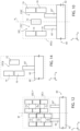
- Figure 12 shows an embodiment wherein, in addition to the first stator cell STC1, a first additional stator cell STC1* of the same type as the first stator cell STC1 is present and stacked to the latter along a corresponding direction parallel to the Y axis.
- the first additional stator cell STC1* is equal to the first stator cell STC1, unless a flip over around a W axis parallel to the Y axis occurs.
- the embodiment shown in Figure 12 may also be controlled in the same manner as described with reference to Figures 8A-8D .
- the first, the second and the third stator regions 70, 72, 74 of the first additional stator cell STC1* are not biased during the driving of the first stator cell STC1; once the driving of the first stator cell STC1 has ended, the same voltages applied respectively to the first, the second and the third stator regions 70, 72, 74 of the first stator cell STC1 and described with reference to Figures 8A-8B are applied to the first, the second and the third stator regions 70, 72, 74 of the first additional stator cell STC1*.
- Figure 13 instead shows an embodiment wherein the internal frame 27 may move bidirectionally, i.e. may move both in a direction concordant with the Y axis, and in an opposite direction.
- each rotor region 64 comprises a respective rear protruding part 66, which protrudes with respect to the overlying connection region 63, in the opposite direction with respect to the Y axis.
- each rear protruding part 66 is symmetrical with respect to a corresponding front protruding part 65.
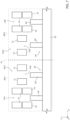
- the rear protruding parts 66 of the transverse region 60 arranged downstream (with respect to the Y axis) form, together with the first and the second stator cells STC1, STC2 and with the front protruding parts 65 of the transverse region 60 arranged upstream (with respect to the Y axis), a symmetrical actuation cell ATCX, which is symmetrical both with respect to the axis of symmetry H and to a transverse symmetry axis SYM, which is perpendicular with respect to the axis of symmetry H.
- the rear protruding parts 66 of the transverse region 60 arranged downstream are symmetrical to the front protruding parts 65 of the transverse region 60 arranged upstream, with respect to the set formed by the first and the second stator cells STC1, STC2.
- the embodiment shown in Figure 13 also comprises a first and a second stator region STC1, STC2 arranged upstream (with respect to the Y axis) of the transverse region 60 arranged further upstream.
- the present MEMS actuator allows to increase the stroke, i.e. the displacements of the shuttle, with reduced sizes and with high stability towards the electrostatic pull-in phenomenon.
- the length of the stroke is not limited by the length of the rotor regions.
- the proposed geometry allows the superimposition area between the shuttle (i.e., the internal frame) and the stator regions to be minimized.
- the MEMS actuator may be obtained by using technological manufacturing processes of a per se known type, such as for example those described in patent application EP 3912953 dated 5/19/2021 in the name of the Applicant, which allow the first and the second epitaxial layers 31, 32 to be patterned so as to obtain the embodiments described.
- the third stator regions 74 may be absent.
- embodiments are possible wherein, for each transverse region 60, even just one base stator cell STCB, shown in Figure 14 , is present which is equal to the balanced stator cell STC e shown in Figure 10 , but includes, in addition to the second stator region 72, only a first stator region 70 and a third stator region 74 (optional), aligned with each other parallel to the Y axis.
- the base stator cell STCB is therefore coupled operationally with the sole first front protruding part 65'. Since electrostatic forces with non-zero components along the X axis, which risk making the first front protruding part 65' contact the stator regions, act on the first front protruding part 65', the voltage V d which is applied alternately to the first, the second or the third stator regions 70, 72, 74 needs to be more limited with respect to what occurs in the other embodiments and/or the first front protruding part 65' needs to be more spaced laterally, along the X axis, with respect to the first, the second and the third stator regions 70, 72, 74, unless a corresponding cell, symmetrical with respect to the base stator cell STCB, is also present.
- number, shape and arrangement of the rotor regions 64 and of the first, the second and the third stator regions 70, 72, 74 are different with respect to what has been described.
- the shapes of the internal frame 27 and/or of the external frame 25, as well as of the first and the second deformable structures 55, 57, are also different with respect to what has been described; for example, the internal frame 27, the external frame 25 and the first and the second deformable structures 55, 57 may be formed in whole or partly by the second epitaxial layer 32.
- the internal frame 27 may be coupled directly to the substrate 21 by one or more deformable structures.
- the external frame 25 described allows the stiffness along the X axis to be increased.
- the MEMS actuator 20 may also be driven in conditions proximate to resonance, so as to further increase the stroke or reduce the actuation voltages.
- first stator regions 72 may be electrically connected to a first electrode 370 (as an example, of a metallic material), as an example through corresponding conductive paths (not shown, formed as an example by polysilicon), which extend in the substrate 21, as an example parallel to the X axis; in the same way, the second and third stator regions 72, 74 may be electrically connected, respectively, to a second and a third electrodes 372, 374, through corresponding conductive paths (not shown).
- first electrode 370 as an example, of a metallic material
- corresponding conductive paths not shown, formed as an example by polysilicon
- the first, second and third electrodes 370, 372, 374 may extend, as an example, under a lower surface S b that delimits the substrate 21 at bottom.
- the rotor regions 64 may be biased through a rotor electrode 364, which is shown in dotted line in Figure 3 ; though not shown in detail, the rotor electrode 364 may be arranged under the lower surface S b of the substrate 21 and may be electrically connected, through corresponding conductive paths (not shown), to the first and/or second pillar regions 45, 46. In this way, the rotor electrode 364 is in electric contact with the front protruding parts 65 of the rotor regions 64.
Landscapes
- Engineering & Computer Science (AREA)
- Computer Hardware Design (AREA)
- Microelectronics & Electronic Packaging (AREA)
- Chemical & Material Sciences (AREA)
- Analytical Chemistry (AREA)
- Micromachines (AREA)
Abstract
Description
- The present invention relates to a long stroke MEMS actuator resilient to the pull-in and to an electronic system including the same.
- As is known, nowadays micro-electro-mechanical (MEMS) actuators are available. For instance,
Figure 1A shows an actuation diagram implemented by aMEMS actuator 1. - In detail, the
MEMS actuator 1 comprises astator region 2, which is integral with a substrate (not shown) of theMEMS actuator 1, and arotor region 3, which forms a so-calledshuttle 4 and arotor actuation region 6. Theshuttle 4 and therotor actuation region 6 form a single piece. - The
rotor region 3 is suspended in acavity 9. In particular, theMEMS actuator 1 comprises a pair ofpillars 10, integral with the substrate; therotor region 3 is mechanically coupled to thepillars 10 by two pairs ofbending beams 11, which function as springs. In particular, a first pair ofbending beams 11 extend between a first side of theshuttle 4 and one of the twopillars 10, while a second pair ofbending beams 11 extend between a second side of theshuttle 4 and theother pillar 11, symmetrically with respect to the first pair ofbending beams 11. - The
stator region 2 forms a plurality of firstelongated elements 13, which are equal to each other and have an elongated shape along an Y axis of an orthogonal XYZ reference system, these firstelongated elements 13 being laterally offset along the X axis. Therotor actuation region 6 forms a plurality of secondelongated elements 15, which are equal to each other and have an elongated shape along the Y axis and are laterally offset along the X axis, so as to be interdigitated with respect to the firstelongated elements 13. In particular, in rest conditions, the first and the secondelongated elements - In practice, the first and the second
elongated elements stator region 2 and therotor region 3, an electrostatic force is generated along the Y axis, which tends to translate therotor region 3 along the Y axis towards the stator region 2 (therefore, this electrostatic force is positive, given the orientation of the XYZ reference system shown inFigure 1A ), with a consequent increase in the extent of the overlapping, in lateral view, between the first and the secondelongated elements Figure 1B . The translation along the Y axis of therotor region 3, and therefore of theshuttle 4, is allowed by thebending beams 11, which are compliant along the Y axis and are rigid along the X axis and along the Z axis. - Moreover, when the
rotor region 3 moves away from the position it has in rest conditions, therotor region 3 is subject to an elastic return force along Y (represented by the elastic constant ktravel indicated inFigure 2 ), which is due to the stiffness, along the Y axis, of thebending beams 11 and has opposite direction with respect to the aforementioned electrostatic force along the Y axis. - In practice, as to the movements of the
rotor region 3 along the Y axis, as the modulus of the voltage present between thestator region 2 and therotor region 3 increases, there occurs an increase in the extent of the translation of therotor region 3 with respect to the rest position, intended as the position assumed by therotor region 3 when a zero voltage is present between thestator region 2 and therotor region 3. In other words, as the modulus of the voltage present between thestator region 2 and therotor region 3 increases, there occurs an increase in the stroke of therotor region 3, and therefore of theshuttle 4. - In addition, when a voltage is present between the
stator region 2 and therotor region 3, therotor region 3 is subject to an electrostatic force along the X axis, which induces a decrease in stiffness along the X axis as the voltage between therotor region 2 and thestator region 3 increases, this decrease being due to an electrostatic constant kelectrical which has a negative value, and whose modulus increases as the voltage present between thestator region 2 and therotor region 3 increases. - Moreover, the
rotor region 3 is subject to an elastic return force along Y (represented by the elastic constant kbearing, indicated inFigure 2 , wherein the shape of therotor region 3 is not exactly consistent with what is shown inFigures 1A-1B , for simplicity of representation), which is due to the stiffness, along the X axis, of thebending beams 11. If the modulus of the electrostatic constant kelectrical exceeds the modulus of the elastic constant kbearing, the so-called pull-in phenomenon occurs, i.e. therotor region 3 becomes unstable and tends to translate along the X axis in an uncontrolled (and undesired) manner, until it contacts thestator region 2. - In practice, since the electrostatic constant kelectrical increases, in modulus, as the voltage present between the
stator region 2 and therotor region 3 increases, this voltage cannot be increased at will in order to increase the stroke of the MEMS actuator. In fact, the need to avoid the undesired pull-in phenomenon puts a limit on the possibility of increasing the stroke by increasing the voltage present between thestator region 2 and therotor region 3; in other words, there exists a limit known as the pull-in voltage, which cannot be exceeded. - In order to partially overcome this problem, solutions have been proposed that seek to increase the stiffness along the X axis of the coupling between the rotor region and the substrate, without increasing the stiffness along the Y axis, but this entails an increase in sizes. Other solutions provide for increasing the lateral distance between the first and the second
elongated elements stator region 2 and therotor region 3, however also these solutions entail an increase in sizes. -
US 6,785,086 discloses a slider for moving a transducing head with respect to a track, which includes a rotor portion, which carries the transducing head and is connected to a stator portion through springs. The stator portion comprises a plurality of stator electrodes; the rotor portion comprises a plurality of rotor electrodes, which are suspended between the stator electrodes. By applying voltages between the stator electrodes and the rotor electrodes, it is possible to generate a force along a lateral direction and a vertical direction, to move the rotor portion with respect to the stator portion. - The paper "A 3-DOF MEMS Electrostatic Piston-Tube actuator", Journal of Microelectromechanical Systems, vol.24, no.4, 1 August 2015, pp. 1173-1184 discloses a further example of MEMS actuator, which includes three degrees of freedom.
- The aim of the present invention is therefore to provide a MEMS actuator which at least partially overcomes the drawbacks of the prior art.
- According to the present invention, a MEMS actuator and a control method are provided as defined in the attached claims.
- For a better understanding of the present invention, preferred embodiments are now described, purely by way of non-limiting example, with reference to the attached drawings, wherein:
-
Figures 1A and 1B schematically show a top view of a portion of a MEMS actuator, respectively in rest conditions and in actuation conditions; -
Figure 2 schematically shows a portion of the MEMS actuator shown inFigures 1A-1B and a mechanical diagram relating to forces that are established in the MEMS actuator; -
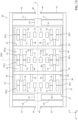
Figure 3 schematically shows a top view with portions removed of the present MEMS actuator, in rest conditions; -
Figure 4 schematically shows a perspective view with portions removed of a portion of the MEMS actuator shown inFigure 3 ; -
Figure 5 schematically shows a top view with portions removed of the present MEMS actuator, in driving conditions; -
Figure 6 schematically shows a lateral view of a part of the portion of the MEMS actuator shown inFigure 4 ; -
Figure 7 schematically shows a top view with portions removed of a pair of actuation cells of the MEMS actuator shown inFigure 3 , in rest conditions; -
Figures 8A-8D schematically show top views with portions removed of one of the actuation cells shown inFigure 7 , during subsequent driving steps of the MEMS actuator; -
Figure 9 schematically shows a top view with portions removed of a pair of actuation cells of a variant of the MEMS actuator, in rest conditions; -
Figure 10 schematically shows a top view with portions removed of an actuation cell of a further variant of the MEMS actuator, in rest conditions; -
Figure 11 schematically shows a top view with portions removed of a set of actuation cells of a further variant of the MEMS actuator, in rest conditions; -
Figure 13 schematically shows a top view with portions removed of a further embodiment of the present MEMS actuator, in rest conditions; and -
Figures 12 and 14 schematically show top views with portions removed of further actuation cells of the MEMS actuator, in rest conditions. -
Figure 3 shows aMEMS actuator 20, which comprises asubstrate 21 of semiconductor material (for example, silicon), which is not shown inFigure 3 , but is visible inFigure 4 . In particular, thesubstrate 21 is delimited upwardly by a front surface Sa, shown inFigure 4 and parallel to the XY plane. - The
MEMS actuator 20 further comprises astator structure 22, which is integral with thesubstrate 21, and arotor structure 23, which is suspended in acavity 24 so as to be movable with respect to thesubstrate 21 and to thestator structure 22. Thecavity 24 extends above thesubstrate 21. - In detail, the
actuator 20 comprises a first and a secondepitaxial layer epitaxial layer 31 extends above thesubstrate 21; the secondepitaxial layer 32 extends above the firstepitaxial layer 31. - Without any loss of generality, the
rotor structure 23 comprises anexternal frame 25, which in turn is formed by a first and a second externallateral region epitaxial layer 31 and have approximately a shape of parallelepipeds elongated along the Y axis and laterally offset along the X axis. - Moreover, the
rotor structure 23 comprises aninternal frame 27, which is formed by a first and a second internallateral region epitaxial layer 31 and have approximately a shape of parallelepipeds elongated along the Y axis and laterally offset along the X axis. In particular, in top view, the first and the second internallateral regions lateral regions lateral regions lateral regions - The
internal frame 27 also comprises a first and a second terminaltransverse region epitaxial layer 31 and have approximately a shape of parallelepipeds elongated along the X axis and laterally offset along the Y axis; moreover, each of the first and the second terminaltransverse regions lateral regions - The
internal frame 27 further comprises a first and asecond coupling region epitaxial layer 31 and are integral with, respectively, a central portion of the first terminaltransverse region 40 and a central portion of the second terminaltransverse region 41. - In greater detail, the first and the
second coupling regions Figure 3 , thefirst coupling region 43 is laterally offset with respect to the first terminaltransverse region 40 in a direction concordant with the Y axis, while thesecond coupling region 44 is laterally offset with respect to the second terminaltransverse region 41 in the opposite direction with respect to the Y axis. - The
MEMS actuator 20 further comprises a pair offirst pillar regions 45 and a pair ofsecond pillar regions 46, which are formed by the firstepitaxial layer 31 and are integral with theunderlying substrate 21. Moreover, thefirst pillar regions 45 are aligned along the Y axis and are laterally offset along the X axis; thesecond pillar regions 46 are arranged symmetrically with respect to thefirst pillar regions 45 with respect to an axis parallel to the X axis. - The
MEMS actuator 20 further comprises a pair of firstinternal springs 50 and a pair of secondinternal springs 51, which are equal to each other, are formed by the firstepitaxial layer 31 and, when therotor structure 23 is in rest conditions, have the shape of parallelepipeds elongated along the X axis. In practice, the first and the secondinternal springs internal springs 50 has ends fixed to thefirst coupling region 43 and to the first externallateral region 33, while the other firstinternal spring 50 has ends fixed to thefirst coupling region 43 and to the second externallateral region 35. One of the secondinternal springs 51 has ends fixed to thesecond coupling region 44 and to the first externallateral region 33, while the other secondinternal spring 51 has ends fixed to thesecond coupling region 44 and to the second externallateral region 35. The first and the secondinternal springs - The
MEMS actuator 20 further comprises a pair of firstexternal springs 52 and a pair of secondexternal springs 53, which are equal to each other, are formed by the firstepitaxial layer 31 and, when therotor structure 23 is in rest conditions, have the shape of parallelepipeds elongated along the X axis. In practice, the first and the secondexternal springs external springs 52 has ends fixed to a correspondingfirst pillar region 45 and to the first externallateral region 33, while the other firstexternal spring 52 has ends fixed to a correspondingfirst pillar region 45 and to the second externallateral region 35. One of the secondexternal springs 53 has ends fixed to a correspondingsecond pillar region 46 and to the first externallateral region 33, while the other secondexternal spring 53 has ends fixed to a correspondingsecond pillar region 46 and to the second externallateral region 35. The first and the secondexternal springs external springs internal springs - In practice, the first and the second
internal springs internal frame 27 to theexternal frame 25; the first and the secondexternal springs external frame 25 to the first and thesecond pillar regions substrate 21. In this manner, both theinternal frame 27 and theexternal frame 25 are suspended in thecavity 24. - Moreover, as explained in greater detail hereinafter, each of the first and the second
internal springs external springs external springs deformable structure 55 which mechanically couples theexternal frame 25 to the first and thesecond pillar regions external frame 25. Moreover, the first and the secondinternal springs deformable structure 57 which mechanically couples theinternal frame 27 to theexternal frame 25, so as to allow the translation, along the Y axis, of theinternal frame 27 with respect to theexternal frame 25. In this manner, it occurs that, assuming that, as explained hereinafter, a translation occurs along the Y axis of an extent equal to ΔY of theinternal frame 27 with respect to the own rest position, a simultaneous translation occurs along the Y axis of an extent equal to ΔY/2 of theexternal frame 25 with respect to the own rest position, as shown for example inFigure 5 ; therefore there occurs a reduction in the stress whereto the first and the secondinternal springs external springs internal frame 27, which functions as a shuttle. In this regard, although not shown in detail, it is anticipated that theMEMS actuator 20 is such that theinternal frame 27 may be connected to a transmission member (not shown), so as to transfer movement and forces from theinternal frame 27 to a generic external element (not shown). - The
internal frame 27 further comprises a plurality (three, in the example ofFigure 3 ) oftransverse regions 60, which are formed by thesecond epitaxial layer 32, are for example equal to each other and are also aligned along a direction parallel to the Y axis; in particular, without any loss of generality, thetransverse regions 60 are evenly spaced along an axis of symmetry H of theMEMS actuator 20, which is parallel to the Y axis. - In greater detail, as better shown in
Figure 4 , eachtransverse region 60 comprises arespective bridge region 62 and a plurality ofconnection regions 63. - The
bridge region 62 has the shape of a parallelepiped elongated along the X axis, with ends integral, respectively, with the underlying first and second internallateral regions connection regions 63 extend below thebridge region 62, in the direction of theunderlying substrate 21. - As visible also in
Figure 6 , indicating with S32bot the bottom surface of thesecond epitaxial layer 32, i.e. the surface parallel to the XY plane that delimits downwardly thesecond epitaxial layer 32, and indicating with S62bot the bottom surface (also parallel to the XY plane) of thebridge region 62, it occurs that the bottom surface S62bot of thebridge region 62 extends to a height (measured along the Z axis) higher with respect to the bottom surface S32bot of thesecond epitaxial layer 32. Moreover, theconnection regions 63 have approximately the shape of parallelepipeds and extend between the bottom surface S62bot of thebridge region 62 and the bottom surface S32bot of thesecond epitaxial layer 32; without any loss of generality, eachconnection region 63 has the same extension along the Y axis as the overlyingbridge region 62. Again without any loss of generality, theconnection regions 63 are equal to each other and are arranged in succession parallel to the X axis. - As shown again in
Figures 4 and6 , the bottom surface S32bot of thesecond epitaxial layer 32 coincides with a surface indicated with S31top, which represents the top surface of thefirst epitaxial layer 31; in this regard, between the first and the second epitaxial layers 31, 32 there is no interface, i.e. a discontinuity. - For each
transverse region 60, theMEMS actuator 20 also comprises a plurality ofrespective rotor regions 64, formed by thefirst epitaxial layer 31. - Without any loss of generality, the
rotor regions 64 are equal to each other; moreover, for eachtransverse region 60, the correspondingrotor regions 64 are arranged in succession parallel to the X axis. - In greater detail, each
rotor region 64 extends below acorresponding connection region 63, with which it forms a single piece. As a first approximation, and without any loss of generality, eachrotor region 64 has the shape of a parallelepiped with a longitudinal axis parallel to the Y axis; moreover, this parallelepiped comprises a respectivefront protruding part 65, which protrudes with respect to theoverlying connection region 63, in a direction concordant with the orientation of the Y axis. In other words, thefront protruding part 65 of eachrotor region 64 protrudes laterally in a direction concordant with the orientation of the Y axis with respect to thecorresponding connection region 63 and to the correspondingbridge region 62. Moreover, as visible inFigure 6 , eachrotor region 64 extends along the Z axis between the bottom surface S32bot of thesecond epitaxial layer 32 and an intermediate surface S64bot, which delimits downwardly therotor regions 64 and overlays, at a distance, the underlying front surface Sa of thesubstrate 21. - In practice, the
rotor regions 64 are suspended above thesubstrate 21, so as to be able to move with respect to thesubstrate 21, as described hereinafter. - The
stator structure 22 comprises, for eachtransverse region 60 of therotor structure 23, a corresponding first stator cell STC1 and a corresponding second stator cell STC2, shown in greater detail inFigure 7 . The first and the second stator cells STC1, STC2 are equal and symmetrical with respect to the axis of symmetry H, therefore only the first stator cell STC1 is described hereinafter. - In detail, the first stator cell STC1 comprises a pair of respective
first stator regions 70, which are formed by thefirst epitaxial layer 31, are for example equal to each other and are arranged aligned along a corresponding direction parallel to the X axis, therefore are symmetrical with respect to a corresponding direction parallel to the Y axis. - In greater detail, the
first stator regions 70 have the shape of parallelepipeds with longitudinal axes parallel to the Y axis and are fixed, downwardly, to the underlying front surface Sa of thesubstrate 21; moreover, thefirst stator regions 70 are delimited upwardly by the top surface S31top of thefirst epitaxial layer 31. - The first stator cell STC1 further comprises a pair of respective
second stator regions 72, which are formed by thefirst epitaxial layer 31, are for example equal to each other and are arranged aligned parallel to a corresponding direction parallel to the X axis, which has a coordinate along the Y axis greater than the coordinate along the Y axis of the direction parallel to the X axis wherealong thefirst stator regions 70 are arranged; in other words, along the Y axis, thesecond stator regions 72 are arranged downstream of thefirst stator regions 70. - The
second stator regions 72 are therefore symmetrical with respect to a corresponding direction parallel to the Y axis. Moreover, the pair ofsecond stator regions 72 is laterally offset along the X axis with respect to the pair offirst stator regions 70; in particular, given the orientation of the X axis shown inFigure 7 , the pair ofsecond stator regions 72 has a coordinate along X greater than the coordinate along X of the first pair ofstator regions 70. - In greater detail, the
second stator regions 72 have the shape of parallelepipeds with longitudinal axes parallel to the Y axis and are fixed, downwardly, to the underlying front surface Sa of thesubstrate 21; moreover, thesecond stator regions 72 are delimited upwardly by the top surface S31top of thefirst epitaxial layer 31. - The first stator cell STC1 further comprises a pair of respective
third stator regions 74, which are formed by thefirst epitaxial layer 31, are for example equal to each other and are arranged aligned along a corresponding direction parallel to the X axis, which has a coordinate along the Y axis greater than the coordinate along the Y axis of the direction parallel to the X axis wherealong thesecond stator regions 72 are aligned; in other words, with respect to the Y axis, thethird stator regions 74 are arranged downstream of thesecond stator regions 72. Moreover, thethird stator regions 74 are symmetrical with respect to a corresponding direction parallel to the Y axis. - In greater detail, the
third stator regions 74 have the shape of parallelepipeds with longitudinal axes parallel to the Y axis and are fixed, downwardly, to the underlying front surface Sa of thesubstrate 21; moreover, thethird stator regions 74 are delimited upwardly by the top surface S31top of thefirst epitaxial layer 31. - Without any loss of generality, each
third stator region 74 is aligned with a correspondingfirst stator region 70, along a corresponding direction parallel to the Y axis; in other words, the pair ofthird stator regions 74 is aligned with the pair offirst stator regions 70 along a corresponding direction parallel to the Y axis. The first and thethird stator regions second stator regions 72 may be equal to the first and thethird stator regions - The pair of
first stator regions 70 and the pair ofthird stator regions 74 laterally delimit a first channel CH1, which extends parallel to the Y axis, is open upwardly and is closed downwardly by thesubstrate 21. The pair ofsecond stator regions 72 laterally delimits a second channel CH2, which extends parallel to the Y axis, is open upwardly and is closed downwardly by thesubstrate 21. The first and the second channels CH1, CH2 are therefore parallel to each other and laterally offset along the X axis. - Moreover, each
second stator region 72 extends on a domain in Y which is partially superimposed on the domains in Y of the first and thethird stator regions second stator regions 72 are offset with respect to the first and thethird stator regions second stator regions 72 are partially superimposed on the projections on the Y axis of the first and thethird stator regions - Even in more detail, as visible in
Figure 7 , which refers to rest conditions, wherein no voltages are applied to the pairs of first, second andthird stator regions rotor regions 64, the first stator cell STC1 is operatively coupled to a corresponding pair of front protruding parts of correspondingrotor regions 64, indicated respectively with 65' and with 65", which are hereinafter referred to as, respectively, the first and the secondfront protruding parts 65', 65". - Without any loss of generality, the first and the second
front protruding parts 65', 65" are adjacent. Moreover, as explained in greater detail hereinafter, the first stator cell STC1 has a geometry such that, in case theinternal frame 27 translates along the axis of symmetry H, and therefore parallel to the Y axis, the first and the secondfront protruding parts 65', 65" may slide respectively along the first and the second channels CH1, CH2, without contacting the first, the second and thethird stator regions front protruding parts 65', 65" are aligned, respectively, with the first and the second channels CH1, CH2. In this manner, theMEMS actuator 20 may be controlled as described hereinafter, with reference, for simplicity, to the sole first stator cell STC1; the second stator cell STC2 is in fact controlled in the same manner as the first stator cell STC1. - In detail, in rest conditions (
Figure 8A ), the first front protruding part 65' is partially inside the first channel CH1, i.e. it is partially interposed between thefirst stator regions 70. In other words, a portion of the first front protruding part 65' faces corresponding portions of thefirst stator regions 70, wherewith it forms a variable capacitor. The secondfront protruding part 65" is instead outside the second channel CH2, i.e. the projection on the Y axis of the secondfront protruding part 65" is separated from the projection on the Y axis of thesecond stator regions 72; the secondfront protruding part 65" therefore does not face thesecond stator regions 72. Moreover, thebridge region 62 is laterally offset with respect to the first and thesecond stator regions - Under these conditions, a voltage Vd is applied to the
first stator regions 70, as shown inFigure 8B , wherein the presence of this voltage on thefirst stator regions 70 is indicated by a circle with a cross. An electrostatic force is thus generated between thefirst stator regions 70 and the first front protruding part 65', which in fact form a variable capacitor; this electrostatic force drags the first front protruding part 65', and therefore also theinternal frame 27, along the axis of symmetry H. This dragging causes the first front protruding part 65' to further penetrate within the first channel CH1 and, at a certain point, the secondfront protruding part 65" to penetrate inside the second channel CH2, i.e. to begin facing thesecond stator regions 72, before the first front protruding part 65' begins to face thethird stator regions 74; in particular, without any loss of generality, when the secondfront protruding part 65" begins to face thesecond stator regions 72, a distal portion of the first front protruding part 65' (intended as the more distant portion from the bridge region 62) has not yet passed thefirst stator regions 70. Moreover, the secondfront protruding part 65" begins to face thesecond stator regions 72 before thebridge region 62 begins to superimpose on thefirst stator regions 70. - As shown in
Figure 8B , after a portion of the secondfront protruding part 65" faces corresponding portions of thesecond stator regions 72, wherewith it forms a corresponding variable capacitor, and before thebridge region 62 begins to superimpose on thefirst stator regions 70, it is possible to cancel the voltage present on thefirst stator regions 70 and apply the voltage Vd to thesecond stator regions 72, as shown inFigure 8C , so as to generate an electrostatic force between thesecond stator regions 72 and the secondfront protruding part 65", which drags the secondfront protruding part 65", so as to continue to drag theinternal frame 27 along the axis of symmetry H, seamlessly. - In practice, owing to the fact that, during the translation of the
internal frame 27 parallel to the Y axis, the secondfront protruding part 65" begins to face corresponding portions of thesecond stator regions 72 before thebridge region 62 begins to superimpose on thefirst stator regions 70, it is possible to cancel the voltage present on thefirst stator regions 70 and apply the voltage Vd to thesecond stator regions 72 before thebridge region 62 begins to superimpose on thefirst stator regions 70. In this manner, when thebridge region 62 begins to superimpose on the first stator regions 70 (without contacting them, given the greater height of the bottom surface S62bot of thebridge region 62 with respect to the top surface S31top which delimits the first stator regions 70), the latter are already voltage-free, so as to avoid the generation of undesired electrostatic forces in the vertical direction, which could compromise the movement of theinternal frame 27. - Again with reference to
Figure 8C , the dragging of theinternal frame 27 operated by the electrostatic force acting on the secondfront protruding part 65" causes, at a certain point, the first front protruding part 65' to begin facing thethird stator regions 74; in particular, in the example shown inFigure 8C , when the first front protruding part 65' begins to face thethird stator regions 74, the distal portion of the secondfront protruding part 65" has not yet passed thesecond stator regions 72. - As shown in
Figure 8C , after a portion of the first front protruding part 65' faces corresponding portions of thethird stator regions 74, wherewith it forms a corresponding variable capacitor, it is possible to cancel the voltage present on thesecond stator regions 72 and apply the voltage Vd to thethird stator regions 74, as shown inFigure 8D , so as to generate an electrostatic force between thethird stator regions 74 and the first front protruding part 65', which drags the first front protruding part 65', so as to continue to drag theinternal frame 27 parallel to the Y axis. Also in this case, the geometry of the front protrudingparts 65 and of thebridge regions 62 is such that, during the translation of theinternal frame 27, the first front protruding part 65' begins to face corresponding portions of thethird stator regions 74 before thebridge region 62 begins to superimpose on thesecond stator regions 72. It is therefore possible to cancel the voltage present on thesecond stator regions 72 and apply the voltage Vd to thethird stator regions 74 before thebridge region 62 begins to superimpose on thesecond stator regions 72, so as to avoid the generation of undesired electrostatic forces in the vertical direction. - Subsequently, after the
internal frame 27 has reached the position of maximum translation with respect to the rest position, i.e. the position wherein, as a first approximation, thethird stator regions 74 face entirely the first front protruding part 65', it is possible to maintain the voltage on thethird stator regions 74, in order to maintain theinternal frame 27 in this position of maximum translation for a desired time. Subsequently, it is possible to cancel the voltage on thethird stator regions 74, so as to allow the elastic return to take theinternal frame 27 back to the rest position. - Again with reference to what is shown in
Figures 8A-8D , it is observed how, although not described in detail, the movement of theinternal frame 27 previously described entails a simultaneous translation along the Y axis also of theexternal frame 25, but of half the extent, as previously mentioned and as qualitatively shown inFigure 5 . Moreover, as previously mentioned, the considerations made about the first stator cell STC1 also apply to the second stator cell STC2; in particular, the first, the second and thethird stator regions third stator regions - Moreover, as shown qualitatively in
Figure 3 , theMEMS actuator 20 comprises acapacitive sensing structure 99 of a per se known type, which is mechanically coupled to theinternal frame 27 so as to generate an electrical signal indicative of the position along the Y axis of theinternal frame 27. For example, although not shown, thecapacitive sensing structure 99 may be formed by facing capacitive plates, formed by portions of the first and the second epitaxial layers 31, 32 and/or by further semiconductive layers not described; alternatively, thecapacitive sensing structure 99 may be formed by a corresponding comb capacitive structure. - This electrical signal may be supplied to an
electronic control device 101, which is electrically coupeable in a releasable manner to theMEMS actuator 20 and is configured to bias the first, the second and thethird stator regions Figures 8A-8D , as a function of the aforementioned electrical signal. To this end, although not shown, theMEMS actuator 20 may comprise for example metallizations electrically coupeable to theelectronic control device 101 so as to allow the first, the second and thethird stator regions rotor regions 64 to be biased. In this regard, although previously the operations ofFigures 8A-8D have been described with reference to the case wherein therotor regions 64 are at zero voltage, it is possible to bias therotor regions 64 to a reference voltage; in this case, the first, the second and thethird stator regions - For practical purposes, the first and the second stator cells STC1, STC2 respectively form a first and a second actuation cell, respectively together with the corresponding first and second
front protruding parts 65' and 65" and with corresponding portions of thebridge region 62. The first and the second actuation cells are indicated inFigure 7 respectively with ATC1 and ATC2 and are symmetrical with respect to the axis of symmetry H, so that balanced forces and torques act as a whole on theinternal frame 27; in fact, inside each of the first and the second actuation cells ATC1, ATC2 it occurs that the forces are locally balanced, while the torques are not. However, owing to the symmetry of the first and the second actuation cells ATC1, ATC2, also the torques are balanced as a whole. - Although not shown, variants are possible wherein the first stator cell STC1, and therefore also the second stator cell STC2, comprises a greater number of pairs of first, second and
third stator regions front protruding parts 65 ofrotor regions 64 in the same manner as previously described. - Moreover, although not shown, embodiments without the
third stator regions 74 are possible; this statement applies in general to all the embodiments described herein, although the absence of thethird stator regions 74 entails a reduction in the stroke of theMEMS actuator 20; moreover, the presence of thethird stator regions 74 allows to implement a configuration of the type of stepper motors. For these reasons, hereinafter embodiments are described which include thethird stator regions 74, unless otherwise specified. -
Figure 9 shows a further embodiment, which is described with reference to the sole differences with respect to the embodiment shown inFigure 7 . - In detail, the first stator cell (indicated with STC1') is operatively coupled, in addition to the first and the second
front protruding parts 65', 65", to a thirdfront protruding part 65‴, which is interposed between the first and the secondfront protruding parts 65', 65". - Moreover, the translation of the
internal frame 27 along the axis of symmetry H causes, while the first and the secondfront protruding parts 65', 65" may slide respectively along the first and the second channels CH1, CH2, the thirdfront protruding part 65‴ to be able to slide into a third channel CH3, which is laterally delimited, on one side, by thefirst stator region 70 facing towards the pair ofsecond stator regions 72 and by the correspondingthird stator region 74, and on the other side by thesecond stator region 72 facing towards saidfirst stator region 70 and correspondingthird stator region 74. Moreover, in rest conditions, the thirdfront protruding part 65‴ partly faces a portion of thefirst stator region 70 facing towards the pair ofsecond stator regions 72, but is laterally separated, along the Y axis, from the aforementionedsecond stator region 72. - In addition, without any loss of generality, an optional
front protruding part 65* may slide into an additional channel CH*, which extends between the first and the second stator cells STC1', STC2', since it is delimited by thesecond stator regions 72 of the first and the second stator cells STC1', STC2' which face on each other. - The presence of the third
front protruding part 65‴, and possibly also of the optionalfront protruding part 65*, allows the force acting on theinternal frame 27 to be increased, as a first approximation without increasing the sizes with respect to the embodiment shown inFigure 7 . - The
MEMS actuator 20 shown inFigure 9 may be controlled by biasing the first, the second and thethird stator regions Figures 8A-8D . In this manner, although not shown, when the voltage Vd is applied to thefirst stator regions 70, the thirdfront protruding part 65‴ is also subject to an electrostatic force; moreover, when the voltage Vd is applied to thesecond stator regions 72, a portion of the thirdfront protruding part 65‴ faces a portion of thesecond stator region 72 which laterally delimits the third channel CH3, therefore the thirdfront protruding part 65‴ is still subject to an electrostatic force. Finally, when the voltage Vd is applied to thethird stator regions 74, a portion of the thirdfront protruding part 65‴ faces a portion of thethird stator region 74 which laterally delimits the third channel CH3, therefore the thirdfront protruding part 65‴ is still subject to an electrostatic force. - In greater detail, while the first and the second
front protruding parts 65', 65" continue to experience electrostatic forces approximately directed only parallel to the Y axis because at every instant they experience, on opposite sides, equal voltages, the thirdfront protruding part 65‴ is subject to electrostatic forces that include a component parallel to the X axis, caused by the asymmetry of the voltages present on the sides of the third channel CH3. This component along X is however balanced by the component along X of the electrostatic forces acting on the thirdfront protruding part 65‴ which is coupled with the second stator cell STC2'. - In practice, referring to the first and the second actuation cells ATC1' and ATC2' to indicate the actuation cells formed by the first and the second stator cells STC1', STC2' with the respective first, second and third
front protruding parts 65', 65", 65‴ and the corresponding portions of thebridge region 62, each of the first and the second actuation cells ATC1' and ATC2' introduces forces and torques acting on theinternal frame 27 in an unbalanced manner, however, owing to the symmetry present between the first and the second actuation cells ATC1' and ATC2', the forces and the torques acting on theinternal frame 27 as a whole are balanced. - There are also possible embodiments wherein the actuation cells are of the type shown in
Figure 10 , wherein the actuation cell is indicated with ATCe and includes a balanced stator cell STCe, which is now described with reference to the differences with respect to the first actuation cell STC1 shown inFigure 7 . - In detail, the balanced stator cell STCe comprises only one
second stator region 72, which, with respect to what is shown inFigure 7 , has the same coordinate along the Y axis, but is translated along the X axis in such a way that a proximal part (intended as the part closest to the bridge region 62) of thesecond stator region 72 is interposed, at a distance, between the twofirst stator regions 70; moreover, a distal part of thesecond stator region 72 is interposed, at a distance, between the twothird stator regions 74. - Consequently, as already occurs in the case of the third channel CH3 of the embodiment shown in
Figure 9 , the first channel (indicated with CH1') is delimited by thesecond stator region 72 and by the first and thethird stator regions second stator region 72, while the second channel (indicated with CH2') is delimited by thesecond stator region 72 and by the first and thethird stator regions second stator region 72. - The first and the second
front protruding parts 65', 65" are respectively aligned with the first and the second channels CH1', CH2', so as to be able to slide therein during the translation parallel to the Y axis of theinternal frame 27. Moreover, both the balanced stator cell STCe and actuation cell ATCe are symmetrical with respect to a cell symmetry axis He, parallel to the Y axis. - The embodiment shown in
Figure 10 may also be controlled in the same manner as described with reference toFigures 8A-8D . Therefore, it occurs that, in rest conditions, portions of the first and the secondfront protruding parts 65', 65" face, each, a portion of a correspondingfirst stator region 70; when the voltage Vd is applied to thefirst stator regions 70, both the first and the secondfront protruding parts 65', 65" are subject to electrostatic forces that drag them. Moreover, when portions of the first and the secondfront protruding parts 65', 65" begin to face the second stator region 72 (before thebridge region 62 begins to superimpose on the first stator regions 70), it is possible to cancel the voltage on thefirst stator regions 70 and apply the voltage Vd to thesecond stator region 72, so that the first and the secondfront protruding parts 65', 65" are still subject to electrostatic forces which drag them. Finally, when portions of the first and the secondfront protruding parts 65', 65" begin to face, each, a corresponding third stator region 74 (before thebridge region 62 begins to superimpose on the second stator region 72), it is possible to cancel the voltage on thesecond stator region 72 and apply the voltage Vd to thethird stator regions 74, so that the first and the secondfront protruding parts 65', 65" are still subject to electrostatic forces which drag them. - In greater detail, the electrostatic forces acting on the first and the second
front protruding parts 65', 65" are the same as described with reference to the thirdfront protruding part 65‴ shown inFigure 9 ; moreover, the components along the X axis of these electrostatic forces balance each other, inside the same actuation cell ATCe. - In practice, owing to the symmetry, forces and torques are generated in the actuation cell ATCe acting locally on the corresponding portion of the
internal frame 27 in a balanced manner. Consequently, although not shown, theMEMS actuator 20 may comprise, for eachtransverse region 60, a plurality of actuation cells ATCe laterally offset parallel to the X axis. - Embodiments are also possible wherein, for each
transverse region 60, combinations of stator cells (and of corresponding actuation cells) previously described are present, which are arranged parallel to the X axis so as to form a symmetrical arrangement with respect to the axis of symmetry H. For example,Figure 11 shows a combination that includes a first and a second balanced stator cell STC1e, STC2e, which form corresponding actuation cells indicated with ATC1e, ATC2e and are arranged respectively on the sides of the first and the second stator cells STC1, STC2 already shown inFigure 7 , so as to ensure the overall balancing of the forces and the torques. - Embodiments of the same type previously described are also possible, but wherein, for each stator cell of each transverse region, one or more additional stator cells of the same type are present, which are stacked together with the stator cell along a corresponding direction parallel to the Y axis, so as to increase the stroke of the
MEMS actuator 20. For example,Figure 12 shows an embodiment wherein, in addition to the first stator cell STC1, a first additional stator cell STC1* of the same type as the first stator cell STC1 is present and stacked to the latter along a corresponding direction parallel to the Y axis. Moreover, the first additional stator cell STC1* is equal to the first stator cell STC1, unless a flip over around a W axis parallel to the Y axis occurs. - The embodiment shown in
Figure 12 may also be controlled in the same manner as described with reference toFigures 8A-8D . In particular, the first, the second and thethird stator regions third stator regions Figures 8A-8B are applied to the first, the second and thethird stator regions - In this manner, the length of the stroke of the
MEMS actuator 20 is further increased. -
Figure 13 instead shows an embodiment wherein theinternal frame 27 may move bidirectionally, i.e. may move both in a direction concordant with the Y axis, and in an opposite direction. - In detail, for each transverse region 60 (two shown in
Figure 13 ), eachrotor region 64 comprises a respectiverear protruding part 66, which protrudes with respect to theoverlying connection region 63, in the opposite direction with respect to the Y axis. - Without any loss of generality, each rear protruding
part 66 is symmetrical with respect to a correspondingfront protruding part 65. Moreover, considering the first and the second stator cells STC1, STC2 extending between a pair of adjacenttransverse regions 60, therear protruding parts 66 of thetransverse region 60 arranged downstream (with respect to the Y axis) form, together with the first and the second stator cells STC1, STC2 and with the front protrudingparts 65 of thetransverse region 60 arranged upstream (with respect to the Y axis), a symmetrical actuation cell ATCX, which is symmetrical both with respect to the axis of symmetry H and to a transverse symmetry axis SYM, which is perpendicular with respect to the axis of symmetry H. In other words, in rest conditions, therear protruding parts 66 of thetransverse region 60 arranged downstream are symmetrical to thefront protruding parts 65 of thetransverse region 60 arranged upstream, with respect to the set formed by the first and the second stator cells STC1, STC2. - In this manner, by biasing the first, the second and the
third stator regions Figures 8A-8D , theinternal frame 27 moves in the same manner. Conversely, by reversing the order in which the first, the second and thethird stator regions internal frame 27 moves in the opposite direction. In fact, in this case it is the rear protrudingparts 66 that experience the electrostatic forces caused by the bias, in succession, of thethird stator regions 74, thesecond stator regions 72 and thefirst stator regions 70. - Without any loss of generality, the embodiment shown in
Figure 13 also comprises a first and a second stator region STC1, STC2 arranged upstream (with respect to the Y axis) of thetransverse region 60 arranged further upstream. - The advantages that the present MEMS actuator affords are clear from the previous description.
- In particular, the present MEMS actuator allows to increase the stroke, i.e. the displacements of the shuttle, with reduced sizes and with high stability towards the electrostatic pull-in phenomenon. In particular, the length of the stroke is not limited by the length of the rotor regions. From another point of view, the proposed geometry allows the superimposition area between the shuttle (i.e., the internal frame) and the stator regions to be minimized.
- Moreover, the MEMS actuator may be obtained by using technological manufacturing processes of a per se known type, such as for example those described in patent application
EP 3912953 dated 5/19/2021 in the name of the Applicant, which allow the first and the second epitaxial layers 31, 32 to be patterned so as to obtain the embodiments described. - Finally, it is clear that modifications and variations may be made to the MEMS actuator described and illustrated herein without thereby departing from the scope of the present invention, as defined in the attached claims.
- In particular, as previously mentioned, the
third stator regions 74 may be absent. Moreover, embodiments are possible wherein, for eachtransverse region 60, even just one base stator cell STCB, shown inFigure 14 , is present which is equal to the balanced stator cell STCe shown inFigure 10 , but includes, in addition to thesecond stator region 72, only afirst stator region 70 and a third stator region 74 (optional), aligned with each other parallel to the Y axis. - The base stator cell STCB is therefore coupled operationally with the sole first front protruding part 65'. Since electrostatic forces with non-zero components along the X axis, which risk making the first front protruding part 65' contact the stator regions, act on the first front protruding part 65', the voltage Vd which is applied alternately to the first, the second or the
third stator regions third stator regions - In general, it is also possible that number, shape and arrangement of the
rotor regions 64 and of the first, the second and thethird stator regions internal frame 27 and/or of theexternal frame 25, as well as of the first and the seconddeformable structures internal frame 27, theexternal frame 25 and the first and the seconddeformable structures second epitaxial layer 32. - Again with reference to the
external frame 25, it is optional, i.e. theinternal frame 27 may be coupled directly to thesubstrate 21 by one or more deformable structures. However, theexternal frame 25 described allows the stiffness along the X axis to be increased. - In addition, although the driving of the
MEMS actuator 20 has been described with reference to direct voltages ("quasi-static" driving), theMEMS actuator 20 may also be driven in conditions proximate to resonance, so as to further increase the stroke or reduce the actuation voltages. - Finally, the biasing of the first, second and third stator regions and the rotor regions may occur in a per se known manner, as an example through corresponding electrodes. As an example, as qualitatively shown in
Figure 4 (but the same considerations apply also to the other embodiments), it is possible for thefirst stator regions 72 to be electrically connected to a first electrode 370 (as an example, of a metallic material), as an example through corresponding conductive paths (not shown, formed as an example by polysilicon), which extend in thesubstrate 21, as an example parallel to the X axis; in the same way, the second andthird stator regions third electrodes third electrodes substrate 21 at bottom. Also therotor regions 64 may be biased through arotor electrode 364, which is shown in dotted line inFigure 3 ; though not shown in detail, therotor electrode 364 may be arranged under the lower surface Sb of thesubstrate 21 and may be electrically connected, through corresponding conductive paths (not shown), to the first and/orsecond pillar regions rotor electrode 364 is in electric contact with the front protrudingparts 65 of therotor regions 64.
Claims (16)
- A MEMS actuator (20) comprising:- a substrate (21);- a first semiconductive layer (31) extending on top of the substrate (21);- a second semiconductive layer (32) extending on top of the first semiconductive layer (31);- a frame (27) comprising a number of transverse regions (62), which are formed by the second semiconductive layer (32), are elongated parallel to a first direction (X) and are offset along a second direction (Y); and- a deformable structure (25,55,57), which is formed by at least one of the first and the second semiconductive layers (31,32) and mechanically couples the frame (27) to the substrate (21), so that the frame (27) is movable with respect to the substrate (21) parallel to the second direction (Y);said MEMS actuator (20) further comprising, for each transverse region (62):- a plurality of corresponding front rotor regions (65), which are formed by the first semiconductive layer (31), are fixed to the transverse region (62) so as to be laterally offset along the transverse region (62) and suspended above the substrate (21), said front rotor regions (65) protruding with respect to the transverse region (62), parallel to the second direction (Y);- at least one respective first stator cell (STC1; STCe) including at least one first stator region (70) and one second stator region (72), which are formed by the first semiconductive layer (31) and are fixed to the substrate (21) in such a way that, along the second direction (Y), the second stator region (72) is arranged downstream of the first stator region (70), the first and the second stator regions (70,72) being further laterally offset along the first direction (X) so as to be partially facing;and wherein said first and second stator regions (70,72) are further arranged in such a way that, when the frame (27) is in a rest position, the transverse region (62) is laterally offset with respect to the first and the second stator regions (70,72) and at least one first front rotor region (65') of said corresponding front rotor regions (65) at least partially faces the first stator region (70), said first and second stator regions (70,72) being further arranged in such a way that, during a translation of the frame (27) along the second direction (Y) from the rest position, the first front rotor region (65') and/or a second front rotor region (65") of said corresponding front rotor regions (65) at least partially face the second stator region (72), when the transverse region (62) begins to superimpose on the first stator region (70).
- The MEMS actuator according to claim 1, further comprising a first and a second stator electrodes (370,372), which are electrically coupled, respectively, to the first and the second stator regions (70,72), and a rotor electrode (364), which is electrically coupled to the front rotor regions (65).
- The MEMS actuator according to claim 1 or 2, which may be electronically controlled to:- apply, when the frame (27) is in the rest position, a voltage between the first stator region (70) and the corresponding front rotor regions (65), so as to apply to the first front rotor region (65') a first electrostatic force which drags the frame (27) along the second direction (Y); and- before the transverse region (62) begins to superimpose on the first stator region (70), cancel said voltage between the first stator region (70) and the corresponding front rotor regions (65) and apply a voltage between the second stator region (72) and the corresponding front rotor regions (65), so as to apply to said first front rotor region (65') and/or to said second front rotor region (65") a second electrostatic force which drags the frame (27) along the second direction (Y).
- The MEMS actuator according to any of the preceding claims, wherein the first stator cell (STCe) comprises a pair of first stator regions (70), which are symmetrical to each other with respect to the second stator region (72); and wherein the first and the second front rotor regions (65',65") are arranged in such a way that, during the translation of the frame (27) along the second direction (Y), the first front rotor region (65') moves partly between the second stator region (72) and a stator region of said pair of first stator regions (70), and the second front rotor region (65") moves partly between the second stator region (72) and the other stator region of said pair of first stator regions (70).
- The MEMS actuator according to claim 4, wherein the first stator cell (STCe) further comprises a pair of third stator regions (74), which are formed by the first semiconductive layer (31), are fixed to the substrate (21) and are respectively aligned, parallel to the second direction (Y), with the pair of first stator regions (70), said third stator regions (74) being further arranged, along the second direction (Y), downstream of the second stator region (72) and being symmetrical to each other with respect to the second stator region (72), said third stator regions (74) partially facing the second stator region (72), in such a way that, during the translation of the frame (27) along the second direction (Y), each of the first and the second front rotor region (65', 65") at least partly faces a respective stator region of said pair of third stator regions (74), when the transverse region (62) begins to superimpose on the second stator region (72).
- The MEMS actuator according to any of the claims from 1 to 3, wherein the first stator cell (STC1) comprises:- a pair of first stator regions (70), which are symmetrical with respect to a corresponding direction parallel to the second direction (Y) and are configured to be biased to a same voltage;- a pair of second stator regions (72), which are symmetrical with respect to a corresponding direction parallel to the second direction (Y) and are configured to be biased to a same voltage, said pair of second stator regions being laterally offset with respect to the pair of first stator regions (70) along the first and the second directions (X,Y);and wherein the pair of first stator regions (70) and the pair of second stator regions (72) are arranged in such a way that, during the translation of the frame (27) along the second direction (Y) from the rest position, the first front rotor region (65') moves partly between the first stator regions (70) and the second front rotor region (65") moves partly between the second stator regions (72).
- The MEMS actuator according to claim 6, wherein the pair of first stator regions (70) and the pair of second stator regions (72) are arranged in such a way that, during the translation of the frame (27) along the second direction (Y), a third front rotor region (65‴) of said corresponding front rotor regions (65) moves partly between the pair of first stator regions (70) and the pair of second stator regions (72).
- The MEMS actuator according to claim 6 or 7, wherein the first stator cell (STC1) further comprises a pair of third stator regions (74), which are formed by the first semiconductive layer (31), are fixed to the substrate (21), are symmetrical with respect to a corresponding direction parallel to the second direction (Y) and are configured to be biased to a same voltage, the third stator regions (74) being further respectively aligned, parallel to the second direction (Y), with the first stator regions (70), the pair of third stator regions (74) being further arranged, along the second direction (Y), downstream of the pair of second stator regions (72), so that one of said third stator regions (74) partly faces one of said second stator regions (72), said pair of third stator regions (74) being further arranged in such a way that, during the translation of the frame (27) along the second direction (Y), the first front rotor region (65') is at least partially interposed between the third stator regions (74), when the transverse region (62) begins to superimpose on the second stator regions (72).
- The MEMS actuator according to any of claims 6 to 8, which comprises, for each transverse region (62), at least one second stator cell (STC2), which is offset, along the first direction (X), with respect to the corresponding first stator cell (STC1) and is symmetrical with respect to the corresponding first stator cell (STC1).
- The MEMS actuator according to any of the preceding claims, further comprising, for each transverse region (62):- a plurality of corresponding rear rotor regions (66), which are formed by the first semiconductive layer (31), are fixed to the transverse region (62), are symmetrical with respect to the corresponding front rotor regions (65) and protrude with respect to the transverse region (62), in the opposite direction with respect to the second direction (Y);and wherein, when the frame (27) is in the rest position, the front rotor regions (65) of a first transverse region (62) and the rear rotor regions (66) of a second transverse region (62) are symmetrical, with respect to the first stator cell (STC1,STC2) of the first transverse region (62) .
- The MEMS actuator according to any of the preceding claims, wherein the front rotor regions (65) are equal to each other.
- The MEMS actuator according to any of the preceding claims, wherein the deformable structure (25,55,57) is compliant parallel to the second direction (Y).
- The MEMS actuator according to any of the preceding claims, wherein the front rotor regions (65) are in electrical contact with the respective transverse region (62) .
- A system comprising the MEMS actuator (20) according to any of the preceding claims and an electronic control device (101), which is electronically coupled to the MEMS actuator (20) and is configured to:- apply, when the frame (27) is in the rest position, a voltage between the first stator region (70) and the corresponding front rotor regions (65), so as to apply to the first front rotor region (65') a first electrostatic force which drags the frame (27) along the second direction (Y) ;- before the transverse region (62) begins to superimpose on the first stator region (70), cancel said voltage between the first stator region (70) and the corresponding front rotor regions (65) and apply a voltage between the second stator region (72) and the corresponding front rotor regions (65), so as to apply to said first front rotor region (65') and/or to said second rotor region (65") a second electrostatic force which drags the frame (27) along the second direction (Y).
- The system according to claim 14, wherein the MEMS actuator (20) comprises a sensing structure (99) configured to generate an electrical signal indicative of the position of the frame (27) along the second direction (Y); and wherein the electronic control device (101) is configured to apply and cancel said voltage between the first stator region (70) and the corresponding front rotor regions (65) and to apply said voltage between the second stator region (72) and the corresponding front rotor regions (65) as a function of said electrical signal.
- A method for controlling the MEMS actuator (20) according to any of claims 1-13, comprising:- applying, when the frame (27) is in the rest position, a voltage between the first stator region (70) and the corresponding front rotor regions (65), so as to apply to the first front rotor region (65') a first electrostatic force which drags the frame (27) along the second direction (Y); and- before the transverse region (62) begins to superimpose on the first stator region (70), cancelling said voltage between the first stator region (70) and the corresponding front rotor regions (65) and applying a voltage between the second stator region (72) and the corresponding front rotor regions (65), so as to apply to said first front rotor region (65') and/or to said second rotor region (65") a second electrostatic force which drags the frame (27) along the second direction (Y).
Applications Claiming Priority (1)
| Application Number | Priority Date | Filing Date | Title |
|---|---|---|---|
| IT102022000002150A IT202200002150A1 (en) | 2022-02-07 | 2022-02-07 | PULL-IN RESILIENT LONG STROKE MEMS ACTUATOR AND ELECTRONIC SYSTEM INCLUDING THE SAME |
Publications (2)
| Publication Number | Publication Date |
|---|---|
| EP4223691A1 true EP4223691A1 (en) | 2023-08-09 |
| EP4223691B1 EP4223691B1 (en) | 2025-04-02 |
Family
ID=81325993
Family Applications (1)
| Application Number | Title | Priority Date | Filing Date |
|---|---|---|---|
| EP23153332.4A Active EP4223691B1 (en) | 2022-02-07 | 2023-01-25 | Long stroke mems actuator resilient to the pull-in and electronic system including the same |
Country Status (3)
| Country | Link |
|---|---|
| US (1) | US12413160B2 (en) |
| EP (1) | EP4223691B1 (en) |
| IT (1) | IT202200002150A1 (en) |
Citations (2)
| Publication number | Priority date | Publication date | Assignee | Title |
|---|---|---|---|---|
| US6785086B1 (en) | 2000-04-05 | 2004-08-31 | Seagate Technology Llc | Transducer-level microactuator with dual-axis control |
| EP3912953A1 (en) | 2020-05-20 | 2021-11-24 | STMicroelectronics S.r.l. | Process for manufacturing a micro-electro-mechanical device, in particular a movement sensor with capacitive control/detection, and mems device |
Family Cites Families (12)
| Publication number | Priority date | Publication date | Assignee | Title |
|---|---|---|---|---|
| JP3003670B2 (en) * | 1998-05-25 | 2000-01-31 | 日本電気株式会社 | Micro actuator and manufacturing method thereof |
| DE69938658D1 (en) | 1999-09-10 | 2008-06-19 | St Microelectronics Srl | Insensitive to mechanical stress microelectromechanical structure |
| EP1083431A1 (en) | 1999-09-10 | 2001-03-14 | STMicroelectronics S.r.l. | Method for compensating the position offset of a capacitive inertial sensor, andcapacitive inertial sensor |
| US20020008922A1 (en) * | 2000-05-31 | 2002-01-24 | Conant Robert A. | Actuator and micromirror for fast beam steering and method of fabricating the same |
| KR100400218B1 (en) * | 2000-08-18 | 2003-10-30 | 삼성전자주식회사 | micro-actuator and manufacturing method therof |
| DE10051973A1 (en) * | 2000-10-20 | 2002-05-02 | Bosch Gmbh Robert | Micromechanical component has seismic mass sprung-mounted by double U spring to be deflectable by external acceleration, stop(s) protrusion for limiting deflection of double U spring |
| JP2005088188A (en) * | 2003-08-12 | 2005-04-07 | Fujitsu Ltd | Micro oscillating device and micro oscillating device driving method |
| DE602004031938D1 (en) | 2004-08-13 | 2011-05-05 | St Microelectronics Srl | Microelectromechanical structure, in particular acceleration sensor, with improved insensitivity to thermal and mechanical stresses |
| JP4540443B2 (en) * | 2004-10-21 | 2010-09-08 | 富士通コンポーネント株式会社 | Electrostatic relay |
| US7942501B2 (en) | 2006-05-19 | 2011-05-17 | Koninklijke Philips Electronics N.V. | Electrostatic actuator for ink jet heads |
| US9200689B2 (en) | 2011-08-15 | 2015-12-01 | The Regents Of The University Of Michigan | Single-axis flexure bearing configurations |
| IT201800007442A1 (en) | 2018-07-23 | 2020-01-23 | PROCESS FOR MANUFACTURING MICROELECTROMECHANICAL DEVICES, IN PARTICULAR ELECTROACOUSTIC MODULES |
-
2022
- 2022-02-07 IT IT102022000002150A patent/IT202200002150A1/en unknown
-
2023
- 2023-01-25 EP EP23153332.4A patent/EP4223691B1/en active Active
- 2023-01-30 US US18/161,740 patent/US12413160B2/en active Active
Patent Citations (2)
| Publication number | Priority date | Publication date | Assignee | Title |
|---|---|---|---|---|
| US6785086B1 (en) | 2000-04-05 | 2004-08-31 | Seagate Technology Llc | Transducer-level microactuator with dual-axis control |
| EP3912953A1 (en) | 2020-05-20 | 2021-11-24 | STMicroelectronics S.r.l. | Process for manufacturing a micro-electro-mechanical device, in particular a movement sensor with capacitive control/detection, and mems device |
Non-Patent Citations (2)
| Title |
|---|
| "A 3-DOF MEMS Electrostatic Piston-Tube actuator", JOURNAL OF MICROELECTROMECHANICAL SYSTEMS, vol. 24, no. 4, 1 August 2015 (2015-08-01), pages 1173 - 1184 |
| FAEZ BA-TIS ET AL: "A 3-DOF MEMS Electrostatic Piston-Tube Actuator", JOURNAL OF MICROELECTROMECHANICAL SYSTEMS., vol. 24, no. 4, 1 August 2015 (2015-08-01), US, pages 1173 - 1184, XP055395524, ISSN: 1057-7157, DOI: 10.1109/JMEMS.2015.2392692 * |
Also Published As
| Publication number | Publication date |
|---|---|
| US20230253895A1 (en) | 2023-08-10 |
| US12413160B2 (en) | 2025-09-09 |
| IT202200002150A1 (en) | 2023-08-07 |
| EP4223691B1 (en) | 2025-04-02 |
Similar Documents
| Publication | Publication Date | Title |
|---|---|---|
| US12565416B2 (en) | MEMS having a large fluidically effective surface | |
| KR101710334B1 (en) | Device comprising a deflectable structure | |
| US6507138B1 (en) | Very compact, high-stability electrostatic actuator featuring contact-free self-limiting displacement | |
| US6753638B2 (en) | Electrostatic actuator for micromechanical systems | |
| AU2009242920A2 (en) | MEMS device with independent rotation in two axes of rotation | |
| EP2377138B1 (en) | Micro-electro-mechanical switch beam construction with minimized beam distortion and method for constructing | |
| JP3709847B2 (en) | Electrostatic actuator | |
| JP2013148707A (en) | Actuator and movable mirror | |
| US7145284B2 (en) | Actuator and micro-electromechanical system device | |
| US12074540B2 (en) | Method of controlling at least two interacting piezoelectric actuators | |
| US9712085B2 (en) | Actuation device with a drive element actuated by crawling | |
| CN220520143U (en) | Microelectromechanical system actuator and electronic system | |
| EP4223691B1 (en) | Long stroke mems actuator resilient to the pull-in and electronic system including the same | |
| US11527968B2 (en) | Method of manufacturing MEMS vibration element and MEMS vibration element | |
| US20120019886A1 (en) | Via structure and method thereof | |
| JP2006170704A (en) | Capacitive acceleration detector | |
| US8729713B2 (en) | Via structure and method thereof | |
| US12003197B2 (en) | Micro-electromechanical device for energy harvesting | |
| DE102010038919B4 (en) | Micromechanical system | |
| US7487678B2 (en) | Z offset MEMS devices and methods | |
| Narimani et al. | Highly Modular Microsystem Inchworm Motor Based on a Nanoscopic Electrostatic Drive | |
| US20190379306A1 (en) | Micro-electromechanical device for energy harvesting | |
| EP3683951A1 (en) | Micro-electromechanical device for energy harvesting | |
| US20070103843A1 (en) | Electrostatic mems components permitting a large vertical displacement | |
| JP2002373829A (en) | Variable capacitor |
Legal Events
| Date | Code | Title | Description |
|---|---|---|---|
| PUAI | Public reference made under article 153(3) epc to a published international application that has entered the european phase |
Free format text: ORIGINAL CODE: 0009012 |
|
| STAA | Information on the status of an ep patent application or granted ep patent |
Free format text: STATUS: THE APPLICATION HAS BEEN PUBLISHED |
|
| AK | Designated contracting states |
Kind code of ref document: A1 Designated state(s): AL AT BE BG CH CY CZ DE DK EE ES FI FR GB GR HR HU IE IS IT LI LT LU LV MC ME MK MT NL NO PL PT RO RS SE SI SK SM TR |
|
| STAA | Information on the status of an ep patent application or granted ep patent |
Free format text: STATUS: REQUEST FOR EXAMINATION WAS MADE |
|
| 17P | Request for examination filed |
Effective date: 20231128 |
|
| RBV | Designated contracting states (corrected) |
Designated state(s): AL AT BE BG CH CY CZ DE DK EE ES FI FR GB GR HR HU IE IS IT LI LT LU LV MC ME MK MT NL NO PL PT RO RS SE SI SK SM TR |
|
| GRAP | Despatch of communication of intention to grant a patent |
Free format text: ORIGINAL CODE: EPIDOSNIGR1 |
|
| STAA | Information on the status of an ep patent application or granted ep patent |
Free format text: STATUS: GRANT OF PATENT IS INTENDED |
|
| INTG | Intention to grant announced |
Effective date: 20241029 |
|
| GRAS | Grant fee paid |
Free format text: ORIGINAL CODE: EPIDOSNIGR3 |
|
| GRAA | (expected) grant |
Free format text: ORIGINAL CODE: 0009210 |
|
| STAA | Information on the status of an ep patent application or granted ep patent |
Free format text: STATUS: THE PATENT HAS BEEN GRANTED |
|
| AK | Designated contracting states |
Kind code of ref document: B1 Designated state(s): AL AT BE BG CH CY CZ DE DK EE ES FI FR GB GR HR HU IE IS IT LI LT LU LV MC ME MK MT NL NO PL PT RO RS SE SI SK SM TR |
|
| REG | Reference to a national code |
Ref country code: GB Ref legal event code: FG4D |
|
| REG | Reference to a national code |
Ref country code: CH Ref legal event code: EP |
|
| REG | Reference to a national code |
Ref country code: IE Ref legal event code: FG4D |
|
| REG | Reference to a national code |
Ref country code: DE Ref legal event code: R096 Ref document number: 602023002632 Country of ref document: DE |
|
| REG | Reference to a national code |
Ref country code: NL Ref legal event code: MP Effective date: 20250402 |
|
| PG25 | Lapsed in a contracting state [announced via postgrant information from national office to epo] |
Ref country code: NL Free format text: LAPSE BECAUSE OF FAILURE TO SUBMIT A TRANSLATION OF THE DESCRIPTION OR TO PAY THE FEE WITHIN THE PRESCRIBED TIME-LIMIT Effective date: 20250402 |
|
| REG | Reference to a national code |
Ref country code: AT Ref legal event code: MK05 Ref document number: 1781174 Country of ref document: AT Kind code of ref document: T Effective date: 20250402 |
|
| PG25 | Lapsed in a contracting state [announced via postgrant information from national office to epo] |
Ref country code: FI Free format text: LAPSE BECAUSE OF FAILURE TO SUBMIT A TRANSLATION OF THE DESCRIPTION OR TO PAY THE FEE WITHIN THE PRESCRIBED TIME-LIMIT Effective date: 20250402 Ref country code: ES Free format text: LAPSE BECAUSE OF FAILURE TO SUBMIT A TRANSLATION OF THE DESCRIPTION OR TO PAY THE FEE WITHIN THE PRESCRIBED TIME-LIMIT Effective date: 20250402 Ref country code: PT Free format text: LAPSE BECAUSE OF FAILURE TO SUBMIT A TRANSLATION OF THE DESCRIPTION OR TO PAY THE FEE WITHIN THE PRESCRIBED TIME-LIMIT Effective date: 20250804 |
|
| REG | Reference to a national code |
Ref country code: LT Ref legal event code: MG9D |
|
| PG25 | Lapsed in a contracting state [announced via postgrant information from national office to epo] |
Ref country code: GR Free format text: LAPSE BECAUSE OF FAILURE TO SUBMIT A TRANSLATION OF THE DESCRIPTION OR TO PAY THE FEE WITHIN THE PRESCRIBED TIME-LIMIT Effective date: 20250703 Ref country code: NO Free format text: LAPSE BECAUSE OF FAILURE TO SUBMIT A TRANSLATION OF THE DESCRIPTION OR TO PAY THE FEE WITHIN THE PRESCRIBED TIME-LIMIT Effective date: 20250702 |
|
| PG25 | Lapsed in a contracting state [announced via postgrant information from national office to epo] |
Ref country code: PL Free format text: LAPSE BECAUSE OF FAILURE TO SUBMIT A TRANSLATION OF THE DESCRIPTION OR TO PAY THE FEE WITHIN THE PRESCRIBED TIME-LIMIT Effective date: 20250402 |
|
| PG25 | Lapsed in a contracting state [announced via postgrant information from national office to epo] |
Ref country code: BG Free format text: LAPSE BECAUSE OF FAILURE TO SUBMIT A TRANSLATION OF THE DESCRIPTION OR TO PAY THE FEE WITHIN THE PRESCRIBED TIME-LIMIT Effective date: 20250402 |
|
| PG25 | Lapsed in a contracting state [announced via postgrant information from national office to epo] |
Ref country code: HR Free format text: LAPSE BECAUSE OF FAILURE TO SUBMIT A TRANSLATION OF THE DESCRIPTION OR TO PAY THE FEE WITHIN THE PRESCRIBED TIME-LIMIT Effective date: 20250402 |
|
| PG25 | Lapsed in a contracting state [announced via postgrant information from national office to epo] |
Ref country code: AT Free format text: LAPSE BECAUSE OF FAILURE TO SUBMIT A TRANSLATION OF THE DESCRIPTION OR TO PAY THE FEE WITHIN THE PRESCRIBED TIME-LIMIT Effective date: 20250402 |
|
| PG25 | Lapsed in a contracting state [announced via postgrant information from national office to epo] |
Ref country code: RS Free format text: LAPSE BECAUSE OF FAILURE TO SUBMIT A TRANSLATION OF THE DESCRIPTION OR TO PAY THE FEE WITHIN THE PRESCRIBED TIME-LIMIT Effective date: 20250702 |
|
| PG25 | Lapsed in a contracting state [announced via postgrant information from national office to epo] |
Ref country code: IS Free format text: LAPSE BECAUSE OF FAILURE TO SUBMIT A TRANSLATION OF THE DESCRIPTION OR TO PAY THE FEE WITHIN THE PRESCRIBED TIME-LIMIT Effective date: 20250802 |
|
| PG25 | Lapsed in a contracting state [announced via postgrant information from national office to epo] |
Ref country code: LV Free format text: LAPSE BECAUSE OF FAILURE TO SUBMIT A TRANSLATION OF THE DESCRIPTION OR TO PAY THE FEE WITHIN THE PRESCRIBED TIME-LIMIT Effective date: 20250402 |
|
| REG | Reference to a national code |
Ref country code: DE Ref legal event code: R097 Ref document number: 602023002632 Country of ref document: DE |
|
| PG25 | Lapsed in a contracting state [announced via postgrant information from national office to epo] |
Ref country code: DK Free format text: LAPSE BECAUSE OF FAILURE TO SUBMIT A TRANSLATION OF THE DESCRIPTION OR TO PAY THE FEE WITHIN THE PRESCRIBED TIME-LIMIT Effective date: 20250402 Ref country code: SM Free format text: LAPSE BECAUSE OF FAILURE TO SUBMIT A TRANSLATION OF THE DESCRIPTION OR TO PAY THE FEE WITHIN THE PRESCRIBED TIME-LIMIT Effective date: 20250402 |
|
| PG25 | Lapsed in a contracting state [announced via postgrant information from national office to epo] |
Ref country code: CZ Free format text: LAPSE BECAUSE OF FAILURE TO SUBMIT A TRANSLATION OF THE DESCRIPTION OR TO PAY THE FEE WITHIN THE PRESCRIBED TIME-LIMIT Effective date: 20250402 |
|
| PG25 | Lapsed in a contracting state [announced via postgrant information from national office to epo] |
Ref country code: EE Free format text: LAPSE BECAUSE OF FAILURE TO SUBMIT A TRANSLATION OF THE DESCRIPTION OR TO PAY THE FEE WITHIN THE PRESCRIBED TIME-LIMIT Effective date: 20250402 |
|
| PG25 | Lapsed in a contracting state [announced via postgrant information from national office to epo] |
Ref country code: SK Free format text: LAPSE BECAUSE OF FAILURE TO SUBMIT A TRANSLATION OF THE DESCRIPTION OR TO PAY THE FEE WITHIN THE PRESCRIBED TIME-LIMIT Effective date: 20250402 |
|
| PG25 | Lapsed in a contracting state [announced via postgrant information from national office to epo] |
Ref country code: IT Free format text: LAPSE BECAUSE OF FAILURE TO SUBMIT A TRANSLATION OF THE DESCRIPTION OR TO PAY THE FEE WITHIN THE PRESCRIBED TIME-LIMIT Effective date: 20250402 |
|
| PLBE | No opposition filed within time limit |
Free format text: ORIGINAL CODE: 0009261 |
|
| STAA | Information on the status of an ep patent application or granted ep patent |
Free format text: STATUS: NO OPPOSITION FILED WITHIN TIME LIMIT |
|
| REG | Reference to a national code |
Ref country code: CH Ref legal event code: L10 Free format text: ST27 STATUS EVENT CODE: U-0-0-L10-L00 (AS PROVIDED BY THE NATIONAL OFFICE) Effective date: 20260211 |
|
| 26N | No opposition filed |
Effective date: 20260105 |
|
| PGFP | Annual fee paid to national office [announced via postgrant information from national office to epo] |
Ref country code: DE Payment date: 20251217 Year of fee payment: 4 |