EP4223526A1 - Data generating program and three-dimensional fabrication system - Google Patents
Data generating program and three-dimensional fabrication system Download PDFInfo
- Publication number
- EP4223526A1 EP4223526A1 EP21874775.6A EP21874775A EP4223526A1 EP 4223526 A1 EP4223526 A1 EP 4223526A1 EP 21874775 A EP21874775 A EP 21874775A EP 4223526 A1 EP4223526 A1 EP 4223526A1
- Authority
- EP
- European Patent Office
- Prior art keywords
- dimensional
- support column
- cutting
- data
- dimensional product
- Prior art date
- Legal status (The legal status is an assumption and is not a legal conclusion. Google has not performed a legal analysis and makes no representation as to the accuracy of the status listed.)
- Granted
Links
Images







Classifications
-
- G—PHYSICS
- G06—COMPUTING OR CALCULATING; COUNTING
- G06T—IMAGE DATA PROCESSING OR GENERATION, IN GENERAL
- G06T17/00—Three-dimensional [3D] modelling for computer graphics
-
- B—PERFORMING OPERATIONS; TRANSPORTING
- B29—WORKING OF PLASTICS; WORKING OF SUBSTANCES IN A PLASTIC STATE IN GENERAL
- B29C—SHAPING OR JOINING OF PLASTICS; SHAPING OF MATERIAL IN A PLASTIC STATE, NOT OTHERWISE PROVIDED FOR; AFTER-TREATMENT OF THE SHAPED PRODUCTS, e.g. REPAIRING
- B29C64/00—Additive manufacturing, i.e. manufacturing of three-dimensional [3D] objects by additive deposition, additive agglomeration or additive layering, e.g. by 3D printing, stereolithography or selective laser sintering
- B29C64/30—Auxiliary operations or equipment
- B29C64/386—Data acquisition or data processing for additive manufacturing
-
- B—PERFORMING OPERATIONS; TRANSPORTING
- B22—CASTING; POWDER METALLURGY
- B22F—WORKING METALLIC POWDER; MANUFACTURE OF ARTICLES FROM METALLIC POWDER; MAKING METALLIC POWDER; APPARATUS OR DEVICES SPECIALLY ADAPTED FOR METALLIC POWDER
- B22F10/00—Additive manufacturing of workpieces or articles from metallic powder
- B22F10/40—Structures for supporting workpieces or articles during manufacture and removed afterwards
- B22F10/47—Structures for supporting workpieces or articles during manufacture and removed afterwards characterised by structural features
-
- B—PERFORMING OPERATIONS; TRANSPORTING
- B22—CASTING; POWDER METALLURGY
- B22F—WORKING METALLIC POWDER; MANUFACTURE OF ARTICLES FROM METALLIC POWDER; MAKING METALLIC POWDER; APPARATUS OR DEVICES SPECIALLY ADAPTED FOR METALLIC POWDER
- B22F10/00—Additive manufacturing of workpieces or articles from metallic powder
- B22F10/60—Treatment of workpieces or articles after build-up
-
- B—PERFORMING OPERATIONS; TRANSPORTING
- B22—CASTING; POWDER METALLURGY
- B22F—WORKING METALLIC POWDER; MANUFACTURE OF ARTICLES FROM METALLIC POWDER; MAKING METALLIC POWDER; APPARATUS OR DEVICES SPECIALLY ADAPTED FOR METALLIC POWDER
- B22F10/00—Additive manufacturing of workpieces or articles from metallic powder
- B22F10/80—Data acquisition or data processing
-
- B—PERFORMING OPERATIONS; TRANSPORTING
- B22—CASTING; POWDER METALLURGY
- B22F—WORKING METALLIC POWDER; MANUFACTURE OF ARTICLES FROM METALLIC POWDER; MAKING METALLIC POWDER; APPARATUS OR DEVICES SPECIALLY ADAPTED FOR METALLIC POWDER
- B22F3/00—Manufacture of workpieces or articles from metallic powder characterised by the manner of compacting or sintering; Apparatus specially adapted therefor ; Presses and furnaces
- B22F3/10—Sintering only
- B22F3/105—Sintering only by using electric current other than for infrared radiant energy, laser radiation or plasma ; by ultrasonic bonding
-
- B—PERFORMING OPERATIONS; TRANSPORTING
- B22—CASTING; POWDER METALLURGY
- B22F—WORKING METALLIC POWDER; MANUFACTURE OF ARTICLES FROM METALLIC POWDER; MAKING METALLIC POWDER; APPARATUS OR DEVICES SPECIALLY ADAPTED FOR METALLIC POWDER
- B22F3/00—Manufacture of workpieces or articles from metallic powder characterised by the manner of compacting or sintering; Apparatus specially adapted therefor ; Presses and furnaces
- B22F3/12—Both compacting and sintering
- B22F3/16—Both compacting and sintering in successive or repeated steps
-
- B—PERFORMING OPERATIONS; TRANSPORTING
- B22—CASTING; POWDER METALLURGY
- B22F—WORKING METALLIC POWDER; MANUFACTURE OF ARTICLES FROM METALLIC POWDER; MAKING METALLIC POWDER; APPARATUS OR DEVICES SPECIALLY ADAPTED FOR METALLIC POWDER
- B22F3/00—Manufacture of workpieces or articles from metallic powder characterised by the manner of compacting or sintering; Apparatus specially adapted therefor ; Presses and furnaces
- B22F3/24—After-treatment of workpieces or articles
-
- B—PERFORMING OPERATIONS; TRANSPORTING
- B29—WORKING OF PLASTICS; WORKING OF SUBSTANCES IN A PLASTIC STATE IN GENERAL
- B29C—SHAPING OR JOINING OF PLASTICS; SHAPING OF MATERIAL IN A PLASTIC STATE, NOT OTHERWISE PROVIDED FOR; AFTER-TREATMENT OF THE SHAPED PRODUCTS, e.g. REPAIRING
- B29C64/00—Additive manufacturing, i.e. manufacturing of three-dimensional [3D] objects by additive deposition, additive agglomeration or additive layering, e.g. by 3D printing, stereolithography or selective laser sintering
- B29C64/30—Auxiliary operations or equipment
- B29C64/386—Data acquisition or data processing for additive manufacturing
- B29C64/393—Data acquisition or data processing for additive manufacturing for controlling or regulating additive manufacturing processes
-
- B—PERFORMING OPERATIONS; TRANSPORTING
- B29—WORKING OF PLASTICS; WORKING OF SUBSTANCES IN A PLASTIC STATE IN GENERAL
- B29C—SHAPING OR JOINING OF PLASTICS; SHAPING OF MATERIAL IN A PLASTIC STATE, NOT OTHERWISE PROVIDED FOR; AFTER-TREATMENT OF THE SHAPED PRODUCTS, e.g. REPAIRING
- B29C64/00—Additive manufacturing, i.e. manufacturing of three-dimensional [3D] objects by additive deposition, additive agglomeration or additive layering, e.g. by 3D printing, stereolithography or selective laser sintering
- B29C64/40—Structures for supporting 3D objects during manufacture and intended to be sacrificed after completion thereof
-
- B—PERFORMING OPERATIONS; TRANSPORTING
- B33—ADDITIVE MANUFACTURING TECHNOLOGY
- B33Y—ADDITIVE MANUFACTURING, i.e. MANUFACTURING OF THREE-DIMENSIONAL [3D] OBJECTS BY ADDITIVE DEPOSITION, ADDITIVE AGGLOMERATION OR ADDITIVE LAYERING, e.g. BY 3D PRINTING, STEREOLITHOGRAPHY OR SELECTIVE LASER SINTERING
- B33Y10/00—Processes of additive manufacturing
-
- B—PERFORMING OPERATIONS; TRANSPORTING
- B33—ADDITIVE MANUFACTURING TECHNOLOGY
- B33Y—ADDITIVE MANUFACTURING, i.e. MANUFACTURING OF THREE-DIMENSIONAL [3D] OBJECTS BY ADDITIVE DEPOSITION, ADDITIVE AGGLOMERATION OR ADDITIVE LAYERING, e.g. BY 3D PRINTING, STEREOLITHOGRAPHY OR SELECTIVE LASER SINTERING
- B33Y30/00—Apparatus for additive manufacturing; Details thereof or accessories therefor
-
- B—PERFORMING OPERATIONS; TRANSPORTING
- B33—ADDITIVE MANUFACTURING TECHNOLOGY
- B33Y—ADDITIVE MANUFACTURING, i.e. MANUFACTURING OF THREE-DIMENSIONAL [3D] OBJECTS BY ADDITIVE DEPOSITION, ADDITIVE AGGLOMERATION OR ADDITIVE LAYERING, e.g. BY 3D PRINTING, STEREOLITHOGRAPHY OR SELECTIVE LASER SINTERING
- B33Y40/00—Auxiliary operations or equipment, e.g. for material handling
- B33Y40/20—Post-treatment, e.g. curing, coating or polishing
-
- B—PERFORMING OPERATIONS; TRANSPORTING
- B33—ADDITIVE MANUFACTURING TECHNOLOGY
- B33Y—ADDITIVE MANUFACTURING, i.e. MANUFACTURING OF THREE-DIMENSIONAL [3D] OBJECTS BY ADDITIVE DEPOSITION, ADDITIVE AGGLOMERATION OR ADDITIVE LAYERING, e.g. BY 3D PRINTING, STEREOLITHOGRAPHY OR SELECTIVE LASER SINTERING
- B33Y50/00—Data acquisition or data processing for additive manufacturing
-
- G—PHYSICS
- G05—CONTROLLING; REGULATING
- G05B—CONTROL OR REGULATING SYSTEMS IN GENERAL; FUNCTIONAL ELEMENTS OF SUCH SYSTEMS; MONITORING OR TESTING ARRANGEMENTS FOR SUCH SYSTEMS OR ELEMENTS
- G05B19/00—Program-control systems
- G05B19/02—Program-control systems electric
- G05B19/18—Numerical control [NC], i.e. automatically operating machines, in particular machine tools, e.g. in a manufacturing environment, so as to execute positioning, movement or co-ordinated operations by means of program data in numerical form
- G05B19/4097—Numerical control [NC], i.e. automatically operating machines, in particular machine tools, e.g. in a manufacturing environment, so as to execute positioning, movement or co-ordinated operations by means of program data in numerical form characterised by using design data to control NC machines, e.g. CAD/CAM
- G05B19/4099—Surface or curve machining, making three-dimensional [3D] objects, e.g. desktop manufacturing
-
- G—PHYSICS
- G06—COMPUTING OR CALCULATING; COUNTING
- G06T—IMAGE DATA PROCESSING OR GENERATION, IN GENERAL
- G06T19/00—Manipulating three-dimensional [3D] models or images for computer graphics
- G06T19/20—Editing of three-dimensional [3D] images, e.g. changing shapes or colours, aligning objects or positioning parts
-
- G—PHYSICS
- G06—COMPUTING OR CALCULATING; COUNTING
- G06T—IMAGE DATA PROCESSING OR GENERATION, IN GENERAL
- G06T2219/00—Indexing scheme for manipulating 3D models or images for computer graphics
- G06T2219/028—Multiple view windows (top-side-front-sagittal-orthogonal)
-
- G—PHYSICS
- G06—COMPUTING OR CALCULATING; COUNTING
- G06T—IMAGE DATA PROCESSING OR GENERATION, IN GENERAL
- G06T2219/00—Indexing scheme for manipulating 3D models or images for computer graphics
- G06T2219/20—Indexing scheme for editing of 3D models
- G06T2219/2021—Shape modification
-
- Y—GENERAL TAGGING OF NEW TECHNOLOGICAL DEVELOPMENTS; GENERAL TAGGING OF CROSS-SECTIONAL TECHNOLOGIES SPANNING OVER SEVERAL SECTIONS OF THE IPC; TECHNICAL SUBJECTS COVERED BY FORMER USPC CROSS-REFERENCE ART COLLECTIONS [XRACs] AND DIGESTS
- Y02—TECHNOLOGIES OR APPLICATIONS FOR MITIGATION OR ADAPTATION AGAINST CLIMATE CHANGE
- Y02P—CLIMATE CHANGE MITIGATION TECHNOLOGIES IN THE PRODUCTION OR PROCESSING OF GOODS
- Y02P10/00—Technologies related to metal processing
- Y02P10/25—Process efficiency
Definitions
- the present invention relates to a data generation program and a three-dimensional modeling system.
- a three-dimensional product manufacturing system including a three-dimensional modeling apparatus which performs three-dimensional modeling based on three-dimensional modeling data, and a machining apparatus which cuts a three-dimensional shaped object in accordance with NC data to produce a three-dimensional product is known (for example, refer to Patent Literature 1).
- the NC data is generated based on three-dimensional modeling data.
- Patent Literature 1 Japanese Patent Application Publication No. 2003-136605
- the three-dimensional modeling data generated by the above modeling apparatus includes data for modeling a support column.
- the support column extends in connection with the three-dimensional product and regulates the position of the three-dimensional product during three-dimensional modeling.
- the three-dimensional modeling apparatus adds data for modeling the support column to three-dimensional modeling data for modeling a three-dimensional product in accordance with the shape of the three-dimensional product.
- the support column is preferably arranged for the three-dimensional product in view of being removed from the three-dimensional product. However, it is a cumbersome task for a designer to arrange a support column for a three-dimensional product considering that the support column is removed from the three-dimensional product.
- the present invention provides a data generation program and a modeling system capable of generating three-dimensional modeling data for modeling a three-dimensional product and a support column connecting to the three-dimensional product by using a three-dimensional modeling apparatus, considering that the support column is removed from the three-dimensional product.
- a data generation program includes instructions for causing a controller of a computer to perform: a data acquisition step of acquiring three-dimensional data representing a three-dimensional shape of a three-dimensional product; a condition acquisition step of acquiring an arrangement condition for arranging a support column to the three-dimensional product, the support column being connected to the three-dimensional product; a direction setting step of setting an extending direction, a width direction, and a height direction of the support column; a cutting-margin addition step of adding a cutting margin of a particular thickness to a cutting surface of the three-dimensional product at one side in the height direction; a support-column setting step of setting the support column in accordance with the arrangement condition, the support column extending in the extending direction, one end of the support column in the extending direction being connected to the cutting margin added to the three-dimensional product; a beam setting step of setting a beam, the beam being spaced from the three-dimensional product having the cutting margin in the extending direction, the beam extending in the
- the computer can generate three-dimensional modeling data for modeling the modeled object by using the three-dimensional modeling apparatus, the modeled object including the three-dimensional product, the cutting margin, the support column, and the beam.
- the support column extends in accordance with the arrangement condition, and the one end of the support column in the extending direction is connected to the cutting margin added to the three-dimensional product.
- the support column is removed together with the cutting margin by removing the cutting margin from the three-dimensional product by the cutting apparatus.
- the data generation program can generate three-dimensional modeling data for modeling the three-dimensional product and the support column connecting to the three-dimensional product by using a three-dimensional modeling apparatus, taking into consideration that the support column is removed from the three-dimensional product.
- a three-dimensional modeling system includes: a data acquisition part that acquires three-dimensional data representing a three-dimensional shape of a three-dimensional product; a condition acquisition part that acquires an arrangement condition for arranging a support column to the three-dimensional product, the support column being connected to the three-dimensional product; a direction setting part that sets an extending direction, a width direction, and a height direction of the support column; a cutting-margin addition part that adds a cutting margin of a particular thickness to a cutting surface of the three-dimensional product at one side in the height direction; a support-column setting part that sets the support column in accordance with the arrangement condition, the support column extending in the extending direction, one end of the support column in the extending direction being connected to the cutting margin added to the three-dimensional product; a beam setting part that sets a beam, the beam being spaced from the three-dimensional product having the cutting margin in the extending direction, the beam extending in the width direction, the beam being connected to an other
- the three-dimensional modeling system of the second aspect has effects similar to the data generation program of the first aspect.
- the three-dimensional modeling system can save the time and effort of the user to generate three-dimensional cutting data separately from three-dimensional modeling data.
- the three-dimensional modeling system can generate the three-dimensional cutting data by using the processing necessary to generate the three-dimensional modeling data, which can simplify processing compared with a case where the three-dimensional cutting data is generated separately from three-dimensional modeling data.
- system 9 A three-dimensional modeling system 9 (hereinafter simply referred to as "system 9") in first and second embodiments of the present invention will be described with reference to the drawings.
- the configurations common to the systems 9 in the first and second embodiments will be described with reference to FIG. 1 and FIG. 2 .
- the system 9 includes a 3D printer 11, a cutting apparatus 12, and a data generation apparatus 1.
- the 3D printer 11 is an apparatus capable of modeling a three-dimensional model based on three-dimensional modeling data.
- the 3D printer 11 may be any known type of powder bed fusion type, directed energy type, binder jetting type, sheet lamination type, photopolymerization curing (stereolithography) type, material extrusion type, and material jetting type, and the type is not particularly limited.
- the cutting apparatus 12 is an apparatus capable of cutting a three-dimensional model into a particular shape by using a tool such as a cutting blade, based on three-dimensional cutting data. For example, the cutting apparatus 12 cuts a three-dimensional model by three-dimensionally moving a tool relative to the three-dimensional model.
- the data generation apparatus 1 is a known personal computer, and generates the three-dimensional modeling data and the three-dimensional cutting data based on the three-dimensional data representing a shape of a three-dimensional product, by executing the data generation program described later.
- the data generation apparatus 1 includes a CPU 2, a ROM 3, a RAM 4, a memory (storage device) 5, an external communication interface 6, a display 7, an operation part 8, and a bus 10.
- the CPU 2 controls the data generation apparatus 1, and is electrically connected to the ROM 3, the RAM 4, the memory 5, the external communication interface 6, the display 7, and the operation part 8, via the bus 10.
- the ROM 3 stores programs such as BIOS to be executed by the CPU 2.
- the RAM 4 temporarily stores various types of data.
- the memory 5 is a nonvolatile memory, and stores programs and various setting values for use in controlling the operation of the data generation apparatus 1.
- the display 7 is configured to display images, and is a liquid crystal display, as an example.
- the operation part 8 allows to input a signal into the CPU 2 in response to the operation performed by a user.
- the operation part 8 is, for example, at least a keyboard, a mouse, a touch panel, or a joystick.
- the external communication interface 6 connects the data generation apparatus 1 to external devices such as the 3D printer 11 and the cutting apparatus 12.
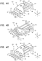
- the outline of the data generation process to be performed by the data generation apparatus 1 of the system 9 will be described by use of specific examples 1 to 3 shown in FIG. 3 and FIGS. 4A-4C .
- the specific examples 1 to 3 differ from each other in the setting of the surfaces to be cut by the cutting apparatus 12.
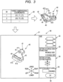
- the data generation apparatus 1 generates the three-dimensional modeling data for use in modeling modeled objects 121, 122, or 123 shown in FIGS. 4A-4C , based on three-dimensional data 20 representing a three-dimensional shape of a three-dimensional product 40 shown in FIG. 3 .
- the three-dimensional data is data generated by a three-dimensional CAD, a three-dimensional modeler, a three-dimensional scanner, and so on.
- the data may be in any format, for example, STL (Standard Triangulated Language), IGES (Initial Graphics Exchange Specification), STEP (Standard for the Exchange of Product model data), or AMF (Additive Manufacturing).
- the three-dimensional data may be generated by the data generation apparatus 1 or by an external apparatus.
- the three-dimensional product 40 is a three-dimensional model that is formed to protrude toward one side, having a particular thickness as a whole, and includes a convex surface 41, a concave surface 42, and cutouts 52, 53.
- the convex surface 41 has a plane part 411, a side surface 412, and an outer peripheral edge 413.
- the plane part 411 extends in a planar shape.
- the plane part 411 of the three-dimensional product 40 has holes 43 to 45 formed to penetrate in the thickness direction.
- the hole 43 is formed in a circular shape, and the holes 44, 45 are formed in rectangular shapes.
- the side surface 412 is connected to the outer periphery of the plane part 411.
- the side surface 412 extends in the direction of intersecting the extension surface of the plane part 411 and separating from the center of the plane part 411 as it separates farther from the plane part 411.
- the outer peripheral edge 413 is the edge of the side surface 412 on the side far from the plane part 411.
- the concave surface 42 is the surface opposite to the convex surface 41.
- the concave surface 42 includes a plane part 421 corresponding to the plane part 411, a side surface 422 corresponding to the side surface 412, and an inner peripheral edge 423 corresponding to the outer peripheral edge 413.
- the cutouts 52, 53 are the portions notched, toward the plane part 421, from the edges 413, 423 formed on the side surfaces 412, 422.
- the convex surface 41 of the three-dimensional product 40 is set as a cutting surface (the surface to be cut).
- the data generation process is performed to generate the three-dimensional modeling data for use in modeling the modeled object 121 including the three-dimensional product 40 added with a cutting margin 56, four columns 71 to 74, a plate-shaped part 75, support columns 81 to 88, and beams 111, 112.
- the cutting margin 56 is added in a particular thickness, on the cutting surface.
- the support columns 81 to 88 regulate the position of the three-dimensional product 40 during the three-dimensional modeling, especially at the time of cutting.
- the data generation apparatus 1 sets one ends of the support columns 81 to 88 so as to be connected to the cutting margin 56, by considering that the cutting apparatus 12 cuts and removes the support columns 81 to 88 from the three-dimensional product 40.
- the data generation apparatus 1 in the present embodiment sets the support columns 81 to 88 at the positions allowing that the one ends of the support columns 81 to 88 are at least partially in contact with an outer peripheral edge 66 of a three-dimensional product 61.
- the concave surface 42 of the three-dimensional product 40 is set as the cutting surface.
- the data generation process is performed to generate the three-dimensional modeling data for use in modeling the modeled object 122 including the three-dimensional product 40 added with a cutting margin 57, the four columns 71 to 74, the plate-shaped part 75, support columns 91 to 98, and beams 113, 114.
- the data generation apparatus 1 sets the support columns 91 to 98 at the positions allowing that one ends of the support columns 91 to 98 are at least partially in contact with an outer peripheral edge 67 of a three-dimensional product 62.
- both the convex surface 41 and the concave surface 42 of the three-dimensional product 40 are set as the cutting surfaces, and the convex surface 41 is cut finally.
- the data generation process is performed to generate the three-dimensional modeling data for use in modeling the modeled object 123 including the three-dimensional product 40 added with a cutting margin 58, the four columns 71 to 74, the plate-shaped parts 75 to 77, support columns 101 to 108, and beams 115, 116.
- the data generation apparatus 1 sets the support columns 101 to 108 at the positions allowing that one ends of the support columns 101 to 108 are at least partially in contact with an outer peripheral edge 68 of a three-dimensional product 63.
- the data generation process to be performed by the CPU 2 of the data generation apparatus 1 in the first embodiment will be described by use of the specific examples 1 to 3, with reference to FIG. 2 to FIG. 14 .
- the data generation process is started, when an instruction to start the process via the operation part 8 is detected in the state where the three-dimensional data 20 to be processed is specified, and subsequently when the CPU 2 reads a program stored in the memory 5 into the RAM 4 and executes the program.
- the data generation process is performed at different timing in the specific examples 1 to 3, the processing to be performed in the examples will be described in parallel for the sake of simplicity of description.
- the three-dimensional data representing the three-dimensional shape of the set three-dimensional model may be added to the three-dimensional data 20 of the three-dimensional product 40, or may be generated separately from the three-dimensional data 20 and stored in association with the three-dimensional data 20.
- the various set values to be referred to in the data generation process may be set in advance, may be automatically set from among multiple types of values according to the shape, the size and so on of the three-dimensional product 40, or may be set by a user via the operation part 8.
- the CPU 2 acquires the three-dimensional data 20 representing the three-dimensional shape of the three-dimensional product 40 (S1).
- the CPU 2 acquires the three-dimensional data 20 in an STL format schematically shown in FIG. 3 from an external device by wire or wireless communication.
- the three-dimensional data 20 in the STL format includes the three-dimensional coordinate data of the vertexes of a group of triangles representing the three-dimensional shape of the three-dimensional product 40.
- the CPU 2 displays, on the display 7, a setting screen 30 (refer to FIG. 3 ) related to the three-dimensional data 20 acquired in S1 (S2).
- the setting screen 30 includes fields 31 to 35 and a key 36.
- the field 31 displays the three-dimensional shape of the three-dimensional product 40 based on the three-dimensional data 20 acquired in S1.
- the CPU 2 initially displays, in the field 31, the three-dimensional shape of the three-dimensional product 40 by setting the X direction, the Y direction and the Z direction in the three-dimensional data 20 as a left-right direction, a front-rear direction, and an upper-lower direction, respectively.
- the positive X side, the positive Y side and the negative Z side correspond to the right side, the rear side and the upper side, respectively.
- the field 32 displays the overall sizes of the three-dimensional product 40 in the X direction, the Y direction and the Z direction based on the three-dimensional data 20 acquired in S1.
- the single-side/double-side setting is specified.
- the single-side/double-side setting is a setting for whether one side face in the height direction of the modeled object is set as the cutting surface (single-side), or both of one side face and the other side face in the height direction of the modeled object are set as the cutting surface (double-side) when the modeled object modeled by the 3D printer 11 is to be cut by the cutting apparatus 12.
- the single-side/double-side setting is selectively performed in a radio button. In the single-side/double-side setting, the single-side is set as the default.
- the one side and the other side in the height direction of the modeled object are set based on the final cutting surface that is finally cut by the cutting apparatus 12.
- the field 34 is a field for setting the final cutting surface.
- the final cutting surface is selectable from among the surface on the positive X side, the surface on the negative X side, the surface on the positive Y side, the surface on the negative Y side, the surface on the positive Z side, and the surface on the negative Z side.
- the surface on the positive Z side is set as the default.
- the field 35 is a field for specifying rotation about the Z axis.
- the field 35 is used to input the rotation angle at which the three-dimensional product 40 displayed in the field 31 rotates about the Z axis.
- the key 36 is operated to confirm and instruct the setting of conditions performed in the setting screen 30.
- the CPU 2 performs the processes of accepting changes in various types of settings via the setting screen 30.
- the CPU 2 determines whether the operation of the key 36 has been detected, based on the output by the operation part 8 (S3). When the operation of the key 36 has not been detected (S3: NO), the CPU 2 determines whether the selection in the setting of the final cutting surface in the field 34 has been detected, based on the output by the operation part 8 (S4). When the selection in the setting of the final cutting surface has been detected (S4: YES), the CPU 2 sets the final cutting surface based on the output by the operation part 8 and changes the three-dimensional shape displayed in the field 31 such that the final cutting surface faces upward (S5), and thereafter returns the processing to S3. In the specific examples 1, 3, the convex surface 41 is set as the final cutting surface.
- the concave surface 42 is set as the final cutting surface.
- the CPU 2 determines whether the selection in the single-side/double-side setting in the field 33 has been detected, based on the output by the operation part 8 (S6).
- the CPU 2 sets single-side or double-side based on the output by the operation part 8 (S7), and thereafter returns the processing to S3.
- single-side is set in the single-side/double-side setting.
- double-side is set in the single-side/double-side setting.
- the CPU 2 determines whether an instruction of the rotation about the Z axis in the field 35 has been detected, based on the output by the operation part 8 (S8).
- an instruction of the rotation about the Z axis has been detected (S8: YES)
- the CPU 2 rotates the three-dimensional product 40 displayed in the field 31, about the Z axis by the rotation angle inputted in the field 35, and changes the three-dimensional product 40 displayed in the field 31 according to the result of the rotation (S9), and thereafter returns the processing to S3.
- no instruction of the rotation about the Z axis has been detected (S8: NO)
- the CPU 2 returns the processing to S3.
- the CPU 2 When in S3 the operation of the key 36 has been detected (S3: YES), the CPU 2 generates three-dimensional modeling data and three-dimensional cutting data based on the settings in the setting screen 30, and performs the processing of outputting the generated data. Specifically, the CPU 2 sets a new Z axis based on the setting in the setting screen 30 (S10). The CPU 2 sets the final cutting surface set in the field 34, to the new positive Z direction. The CPU 2 sets a new X axis and a new Y axis (S11).
- the CPU 2 sets, as the new X axis and the new Y axis, the longitudinal direction and the short direction, respectively, of the projected figure that is acquired when the three-dimensional product 40 is projected from the positive Z direction set in S11 onto the imaginary XY plane perpendicular to the Z axis.
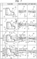
- the CPU 2 performs the conversion of the three-dimensional data acquired in S1, based on the X axis, the Y axis and the Z axis newly set in S10 and S11. In the specific examples 1, 3, the X axis, the Y axis and the Z axis are set as shown in the row of S11 in FIG. 6 .
- the X axis, the Y axis and the Z axis are set as shown in the row of S11 in FIG. 7 .
- the plan view shows the object viewed from the positive Z side; the right side view shows the object viewed from the positive X side; and the left side view shows the object viewed from the negative X side.
- the CPU 2 sets the four columns 71 to 74 for the three-dimensional product 40, based on the three-dimensional data converted according to the new X axis, the new Y axis, and the new Z axis (S12).
- the four columns 71 to 74 are disposed apart from the three-dimensional product 40 so as to extend in the Z direction, and are used to position the three-dimensional product 40 at the time of the three-dimensional modeling by the 3D printer 11.
- the CPU 2 uses, for example, the following procedure to set the four columns 71 to 74 for the three-dimensional product 40.
- the CPU 2 defines a smallest rectangular parallelepiped J that circumscribes the three-dimensional product 40, based on the minimum value of the X coordinate, the maximum value of the X coordinate, the minimum value of the Y coordinate, the maximum value of the Y coordinate, the minimum value of the Z coordinate, and the maximum value of the Z coordinate of the converted three-dimensional data.
- the rectangular parallelepiped J has two planes parallel to the XY plane, two planes parallel to the YZ plane, and two planes parallel to the ZX plane.
- the CPU 2 sets, as the positions of the center axes of the columns, the points which are away from four vertexes P1 to P4 on a plane parallel to the XY plane in the directions away from the center of the three-dimensional product 40, by a particular distance D1 in the X direction and a particular distance D2 in the Y direction, respectively.
- the coordinates (X, Y) of the four vertexes P1 to P4 are respectively (the minimum value of the X coordinate, the minimum value of the Y coordinate), (the minimum value of the X coordinate, the maximum value of the Y coordinate), (the maximum value of the X coordinate, the minimum value of the Y coordinate), and (the maximum value of the X coordinate, the maximum value of the Y coordinate).
- the coordinates (X, Y) of the center axes corresponding to the four vertexes P1 to P4 are respectively (the value acquired by subtracting D1 from the minimum value of the X coordinate, the value acquired by subtracting D2 from the minimum value of the Y coordinate), (the value acquired by subtracting D1 from the minimum value of the X coordinate, the value acquired by adding D2 to the maximum value of the Y coordinate), (the value acquired by adding D1 to the maximum value of the X coordinate, the value acquired by subtracting D2 from the minimum value of the Y coordinate), and (the value by adding D1 to the maximum value of the X coordinate, the value acquired by adding D2 to the maximum value of the Y coordinate).
- the CPU 2 sets, as the extension range in the Z direction of the four columns 71 to 74, the range from the coordinate which is smaller by a particular value D3 than the minimum value of the Z coordinate of the three-dimensional product 40 (the value acquired by subtracting D3 from the minimum value of the Z coordinate) to the coordinate which is larger by a particular value D4 than the maximum value of the Z coordinate of the three-dimensional product 40 (the value acquired by adding D4 to the maximum value of the Z coordinate).
- the CPU 2 sets, as the four columns 71 to 74, the circular columns so as to extend in the set extension range in the Z direction and have a particular radius with the set center axes.
- the shape, the arrangement, the size, the extension range, and so on, of the columns 71 to 74 set in S12 may be changed as appropriate.
- the CPU 2 sets a processing origin (S13).
- the processing origin is the machine origin serving as the reference used when the 3D printer 11 models the modeled object, and also the machine origin serving as the reference used when the cutting apparatus 12 cuts the modeled object.
- the processing origin for the 3D printer 11 and the processing origin for the cutting apparatus 12 may be different from each other.
- the CPU 2 sets, as the processing origin, the position of the column 71 set in the negative X direction and the negative Y direction with respect to the three-dimensional product 40, among the positions of the four columns 71 to 74 set in S12.
- the CPU 2 determines whether single-side has been set in the single-side/double-side setting (S14).
- the CPU 2 adds the plate-shaped part 75, as the mark of the processing origin, to the column 71 (the column set in the negative X direction and the negative Y direction among the four columns 71 to 74) in the three-dimensional product 40 (S15).
- the plate-shaped part 75 has a particular length in the positive X direction and a particular width in the positive Y direction from the center axis of the column 71.
- the CPU 2 adds the cutting margin 56 having a particular thickness to the entirety of the convex surface 41 which serves as the cutting surface on the positive Z side of the three-dimensional product 40 (S16).
- the three-dimensional product 40 to which the cutting margin 56 is added is simply referred to as the three-dimensional product 61
- the outer peripheral edge 413 to which the cutting margin 56 is added is simply referred to as the outer peripheral edge 66.
- the specific example 2 as shown in the row of S16 in FIG.
- the CPU 2 adds the plate-shaped part 75 to the column 71 among the columns 71 to 74 (S15), and adds the cutting margin 57 having a particular thickness to the entirety of the concave surface 42 and the surface between the inner peripheral edge 423 and the outer peripheral edge 413 (S16).
- the three-dimensional product 40 to which the cutting margin 57 is added is simply referred to as the three-dimensional product 62
- the outer peripheral edge 413 to which the cutting margin 57 is added is simply referred to as the outer peripheral edge 67.
- the CPU 2 determines that double-side has been set in the single-side/double-side setting (S14: No). As shown in the row of S18 in FIG. 8 , the CPU 2 adds the plate-shaped parts 75 and 76, as the mark of the processing origin, to the column 71 (the column set in the negative X direction and the negative Y direction among the four columns 71 to 74) in the three-dimensional product 40 (S17).
- the plate-shaped part 75 has a particular length in the positive X direction and a particular width in the positive Y direction from the center axis of the column 71.
- the plate-shaped part 76 has a particular length in the positive X direction and a particular width in the negative Y direction from the center axis of the column 71.
- the CPU 2 further adds the plate-shaped part 77 to the column 72 (the column set in the negative X direction and the positive Y direction) in the three-dimensional product 40.
- the plate-shaped part 77 has a particular length in the positive X direction and a particular width in the negative Y direction from the center axis of the column.
- the CPU 2 adds the cutting margin 58 having a particular thickness to the surfaces to be cut on the positive Z side and the negative Z side of the three-dimensional product 40, that is, to the entirety of the convex surface 41 and to the entirety of the concave surface 42 (S18).
- the three-dimensional product 40 to which the cutting margin 58 is added is simply referred to as the three-dimensional product 63
- the outer peripheral edge 413 to which the cutting margin 58 is added is simply referred to as the outer peripheral edge 68.
- one of the cutting margins 56 to 58 having particular thicknesses is added to the outer peripheral edge 413 of the three-dimensional product 40, depending on whether the cutting surface of the three-dimensional product 40 is the convex surface 41, the concave surface 42, or both the convex surface 41 and the concave surface 42.
- the CPU 2 After S16 or S18, the CPU 2 performs a support column setting process (S19).
- a support column formed to extend in an extending direction according to arrangement conditions is set such that one end of the support column in the extending direction is connected to the cutting margin added to the three-dimensional product 40.
- the support column setting process in the specific examples 1 and 2 will be described with reference to FIG. 5 and FIG. 9 to FIG. 14 .
- the support column setting process in the specific example 3 is the same as the processing in the specific example 1, and the description thereof is thus omitted.
- the CPU 2 acquires the arrangement conditions indicating under what conditions the support columns are arranged for the three-dimensional product 61 or 62 (S30).
- the arrangement conditions may be set in advance, may be set automatically according to the shape, the size and so on of the three-dimensional product 61 or 62, or may be set by a user.
- the arrangement conditions in the present embodiment are set automatically, regardless of the shape, the size and so on of the three-dimensional product 61 or 62, and include a width Q in the width direction of the support column, a height H in the height direction of the support column, and a pitch P in the width direction which is a distance corresponding to an interval between adjacent support columns.
- the pitch P in the width direction of adjacent support columns is set by considering the width in the width direction of adj acent support columns. When set without considering the width in the width direction of adj acent support columns, the pitch P may be an interval in the width direction of adjacent support columns.
- the CPU 2 sets the width direction and the extending direction of the support columns (S31).
- the width direction and the extending direction of the support columns may be automatically set according to the shape, the size and so on of the three-dimensional product 40, or may be set by a user.
- the CPU 2 in the present embodiment automatically sets the X, Y, and Z directions based on the XYZ coordinate system set in S10 and S11. That is, the X direction is the extending direction of the support columns, the Y direction is the width direction of the support columns, and the Z direction is the height direction of the support columns.
- the CPU 2 sets, according to the arrangement conditions acquired in S30, the extension ranges in the width direction of the support columns set for the three-dimensional product 61 or 62 (S32).
- the CPU 2 sets extension ranges R1 to R4 of the support columns according to an equation (1).
- a center D in the Y direction of the three-dimensional product 61 is used as a reference;
- a distance E is the distance between the center D and the support column adjacent to the center D;
- the pitch P is the distance in the width direction of adjacent support columns;
- the width Q is the width in the width direction of the support columns.
- the variables in the equation (1) are set so as to satisfy an equation (2).
- n in the equations 1 and 2 is an integer.
- Y D ⁇ E , D ⁇ E + P ⁇ n Maximum size of three ⁇ dimensional product in Y direction / 2 > E + P ⁇ n + Q
- the extension ranges R1 to R4 for the three-dimensional product 61 are set in the order from the positive Y direction side.
- the CPU 2 sets the extension ranges R1 to R4 of the support columns.
- the CPU 2 sets 1 as a variable N (S33).
- the variable N is used to read out the extension ranges R1 to R4 of the support columns set in S33 in the order from the range on the positive Y side.
- the CPU 2 sets the positive extending direction as a setting direction, and sets the maximum value in the extending direction as a coordinate condition (S34).
- the setting direction is the extending direction of the support columns for the three-dimensional product 61, 62.
- the coordinate condition is a condition for identifying the outer peripheral edge 66, 67 of the three-dimensional product 61, 62.
- the coordinate condition is the maximum value in the extending direction.
- the coordinate condition is the minimum value in the extending direction.
- the CPU 2 identifies the maximum value of the Y coordinate in the extension range of the Nth support column as the coordinate of one end in the width direction in the extension range of the Nth support column, and sets 1 as a variable M (S35).
- the variable M is used to read out ranges obtained by dividing each of the extension ranges R1 to R4 set in S33 by a width K into a plurality of ranges, in the order from the range on the positive Y side.
- the CPU 2 in the present embodiment divides each of the extension ranges R1 to R4 by the width K into ten ranges, and reads out ranges U1 to U10 in this order.
- the CPU 2 sets the Mth range in the extension range of the Nth support column, according to the coordinate identified in S35, the variable M, and the width K (S36).
- the range U1 shown in FIG. 9 is set as the Mth range in the extension range of the Nth support column.
- the CPU 2 identifies the outer peripheral edge 66 of the three-dimensional product 61 in the range set in S36 according to the coordinate condition set in S34 or S48.
- the CPU 2 identifies the outer peripheral edge 67 of the three-dimensional product 61 in the range set in S36 according to the coordinate condition set in S34 or S48 (S37).
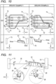
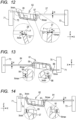
- FIG. 10 shows a cross-sectional view of the specific example 1 taken along a B-B line shown in the row of S33, viewed from the direction of the arrow.
- the row of S37 of the specific example 2 shows a cross-sectional view of the specific example 2 taken along a C-C line shown in the row of S33, viewed from the direction of the arrow.
- the CPU 2 identifies a point Xmax having the maximum value of the X coordinate of the three-dimensional product 61, as the coordinate of the outer peripheral edge 66 in the range set in S36, and stores the point Xmax in association with the variable N and the variable M.
- the CPU 2 identifies the point Xmax having the maximum value of the X coordinate of the three-dimensional product 62, as the coordinate of the outer peripheral edge 67 in the range set in S36, and stores the point Xmax in association with the variable N and the variable M.
- the CPU 2 determines whether the Mth range set in S36 includes the other end in the width direction in the extension range of the Nth support column (S38).
- the CPU 2 in the present embodiment determines that the Mth range includes the other end in the width direction in the extension range of the Nth support column.
- the CPU 2 increments the variable M by 1 (S39), and thereafter returns the processing to S36.
- the repeated execution of S37 allows to acquire ten coordinates respectively corresponding to the ranges U1 to U10 for the extension range of the Nth support column.
- the CPU 2 When the set Mth range includes the other end in the width direction in the extension range of the Nth support column (S3 8: YES), the CPU 2 temporarily sets the Nth support column that extends in the setting direction set in S34, within the extension range of the Nth support column, for the three-dimensional product 61 or 62 (S40). The CPU 2 temporarily sets the Nth support column that extends in the setting direction for the three-dimensional product 61 or 62 in accordance with the following procedure, for example. As shown in FIG.
- the CPU 2 sets a point F which is separated from the point Xmax having the maximum value in the X direction by a particular distance G in the negative X side and separated by a height H in the positive Z side, with respect to each of the plurality of coordinates identified in S37.
- the CPU 2 sets the extension range in the height direction of the support column (the extension range in the Z direction) from the point Xmax to the point F, and sets the extension range in the extending direction (the extension range in the Z direction) from the point F to the center axes of the columns 73, 74 positioned in the positive X side with respect to the three-dimensional product 61.
- the CPU 2 temporarily sets, to the three-dimensional product 61, the three-dimensional model extending in the extension range in the extending direction, the extension range in the height direction of the support column, and the extension range in the width direction of the support column set in S32, as a fourth support column 25 of the specific example 1 that extends in the setting direction.
- the CPU 2 temporarily sets, to the three-dimensional product 62, the three-dimensional model extending in the extension range in the extending direction of the support column, the extension range in the height direction of the support column, and the extension range in the width direction set in S32, as a first support column 27 of the specific example 2 that extends in the setting direction.
- the CPU 2 determines whether there is an intersection between the three-dimensional product 61 and the positive Z-side surface of the support column 25, 27 temporarily set in S40 (S41). When there is an intersection as in the support column 25 of the specific example 1 (S41: YES), the CPU 2 performs a process of setting a support column on the convex surface 41 (S42). Specifically, as shown in FIG. 13 , the CPU 2 identifies the intersection surface where the support column 25 temporarily set in S40 and the three-dimensional product 61 intersect each other, changes the end on the negative X side of the support column 25 temporarily set in S40 to the identified intersection surface, and sets the Nth support column 84 that extends in the setting direction set in S34 to the three-dimensional product 61.
- the support column 84 is set such that the end on the negative X side of the support column 84 is connected to the cutting margin 56 of the three-dimensional product 61.
- the CPU 2 performs a process of setting a support column on the concave surface 42 (S43). Specifically, as shown in FIG. 14 , the CPU 2 identifies the intersection surface where the support column 27 temporarily set in S40 and the three-dimensional product 62 intersect each other, changes the end on the negative X side of the support column 27 temporarily set in S40 to the identified intersection surface, and sets the first support column 91 that extends in the setting direction set in S34, to the three-dimensional product 62.
- the CPU 2 extends the negative Z-side surface of the support column 27 temporarily set in S40 to the position at which the support column 27 makes contact with the three-dimensional product 62, toward the negative Z side.
- the CPU 2 determines whether the setting direction is the positive extending direction (S44).
- the setting direction is the positive extending direction (S44: YES)
- the CPU 2 sets the negative extending direction as the setting direction, and sets the minimum value in the extending direction as the coordinate condition (S48), and thereafter returns the processing to S35 to perform the processing of setting the Nth support column that extends in the negative extending direction to the three-dimensional product 61, 62 (from S35 to S43).
- the CPU 2 In the process of S37 of setting the Nth support column that extends in the negative extending direction to the three-dimensional product 61, 62, as shown in the row of S37 in FIG. 10 , in the specific example 1, 2, the CPU 2 identifies a point Xmin having the minimum value of the X coordinate in the three-dimensional product 61, 62 as the coordinate of the outer peripheral edge 66, 67 in the range set in S36, and stores the point Xmin in association with the variable N and the variable M. In the specific example 1, as shown in FIG. 11 , the CPU 2 temporarily sets a support column 26 (S40). As shown in FIG.
- the CPU 2 identifies the intersection surface where the support column 26 temporarily set in S40 and the three-dimensional product 61 intersect each other, changes the end on the positive X side of the support column 26 temporarily set in S40 to the identified intersection surface, and sets the fourth support column 88 that extends in the setting direction set in S48, to the three-dimensional product 61 (S42).
- the support column 88 is set such that the end on the positive X side of the support column 88 is connected to the cutting margin 56 of the three-dimensional product 61.
- the CPU 2 temporarily sets a support column 28 (S40). As shown in FIG.
- the CPU 2 extends the negative Z-side surface of the support column 28 temporarily set in S40 to the position where the support column 28 makes contact with the three-dimensional product 62 on the negative Z side, and sets the first support column 95 that extends in the setting direction set in S48, to the three-dimensional product 62 (S42).
- the support column 95 is set such that the negative Z-side surface of the end on the positive X side of the support column 95 is connected to the cutting margin 57 of the three-dimensional product 62.
- the CPU 2 determines whether the variable N is the number of the extension ranges set in S32 (S46). In the specific examples 1, 2, when the variable N is not 4 (S46: NO), the CPU 2 increments the variable N by 1 (S47), and thereafter returns the processing to S34.
- the support column setting process by the CPU 2 is completed by the processing above, and the CPU 2 returns the processing to the data generation process shown in FIG. 2 .
- the support column setting process is performed to set, in the specific example 1, the support columns 81 to 88 formed to extend in the X direction as the longitudinal directions thereof, as shown in the row of S19 in FIG. 6 .
- Each of the positive Z-side surfaces and the negative Z-side surfaces of the support columns 81 to 84 is curved or inclined according to the shape of the outer peripheral edge 66.
- Each of the positive Z-side surfaces and the negative Z-side surfaces of the support columns 85 to 88 is formed to extend in parallel to the XY plane according to the shape of the outer peripheral edge 66.
- the support columns 91 to 98 are set so as to extend in the X direction as the longitudinal directions thereof.
- the support columns 101 to 108 are set so as to extend in the X direction as the longitudinal directions thereof.
- the CPU 2 sets beams for the three-dimensional product 61 to 63 (S20). As shown in the row of S20 in FIG. 6 , in the specific example 1, the beams 111, 112 for the three-dimensional product 61 are set so as to be separated from the three-dimensional product 61 in the extending direction of the support columns 81 to 88, and formed to extend in the width direction of the support columns 81 to 88 so as to be connected to the other ends of the support columns 81 to 88 on the sides far from the three-dimensional product 61 of the both ends in the extending direction.
- both ends of the beam 111 in the Y direction are connected to the columns 73, 74 set in S12, and both ends of the beam 112 in the Y direction are connected to the columns 71, 72 set in S12.
- the CPU 2 performs the following procedure to set the beams 111, 112.
- the CPU 2 sets the extension ranges in the X direction and the Y direction of the beams 111, 112, based on the four columns 71 to 74 set in S12.
- the CPU 2 sets the end in the negative X direction of the extension range in the X direction of the beam between the columns 71, 72 at the position separated from the centers in the X direction of the columns 71, 72 by a distance D5 in the negative X direction.
- the distance D5 is longer than zero, and shorter than the radius of the columns 71, 73.
- the CPU 2 sets the end in the positive X direction of the extension range in the X direction of the beam 112 between the columns 71, 72, at the position of the ends in the positive X direction of the columns 71, 72.
- the CPU 2 sets the end in the positive X direction of the extension range in the X direction of the beam 111 between the columns 73, 74, at the position separated from the centers in the X direction of the columns 73, 74, by the distance D5 in the negative X direction.
- the CPU 2 sets the end in the negative X direction of the extension range in the X direction of the beam 111 between the columns 73, 74, at the position of the end in the negative X direction of the columns 71, 72.
- the CPU 2 sets the extension range in the Z direction of the beam 111 from the minimum value to the maximum value in the Z direction of the support columns 81 to 84 connected to the beam 111.
- the CPU 2 sets the extension range in the Z direction of the beam 112 from the minimum value to the maximum value in the Z direction of the support columns 85 to 88 connected to the beam 112.
- the CPU 2 sets the beams 111, 112 in quadrangular prism shapes so as to extend in the Y direction as the longitudinal directions thereof, based on the set extension ranges in the X direction, the Y direction and the Z direction.
- the three-dimensional model including the three-dimensional product 61, the four columns 71 to 74, the plate-shaped part 75, the support columns 81 to 88, and the beams 111, 112 is also referred to as the modeled object 121.
- the beams 113, 114 are set in a similar procedure so as to extend in the Y direction as the longitudinal directions thereof.
- the three-dimensional model including the three-dimensional product 62, the four columns 71 to 74, the plate-shaped part 75, the support columns 91 to 98, and the beams 113, 114 is also referred to as the modeled object 122. As shown in the row of S20 in FIG.
- the beams 115, 116 are set so as to extend in the Y direction as the longitudinal directions thereof.
- the three-dimensional model including the three-dimensional product 63, the four columns 71 to 74, the plate-shaped parts 75 to 77, the support columns 101 to 108, and the beams 115, 116 is also referred to as the modeled object 123.
- the CPU 2 generates the three-dimensional modeling data for use in modeling the modeled object 121 to 123 by the 3D printer 11 (S21).
- the format of the three-dimensional modeling data may be appropriately determined according to the format for modeling by the 3D printer 11.
- the three-dimensional modeling data in the specific example 1 includes the data for use in modeling the modeled object 121, that is, the data representing the respective three-dimensional shapes of the three-dimensional product 40, the four columns 71 to 74 set in S12, the plate-shaped part 75 serving as the marker added in S15, the cutting margin 56 added in S16, the support columns 81 to 88 set in S19, and the beams 111, 112 set in S20.
- the CPU 2 generates the three-dimensional cutting data for use in cutting the three-dimensional product 40 (S22).
- the three-dimensional cutting data represents the shape of the three-dimensional model that remains after the cutting by the cutting apparatus 12.
- the three-dimensional cutting data in the specific example 1 includes the data representing the three-dimensional shape of the four columns 71 to 74 set in S12, the plate-shaped part 75 added in S15, and the three-dimensional product 40.
- the CPU 2 acquires the difference between the three-dimensional modeling data generated in S21 and the three-dimensional cutting data generated in S22 (S23).
- the CPU 2 acquires the data representing the respective three-dimensional shapes of the cutting margin 56 added in S16, the support columns 81 to 88 set in S19, and the beams 111, 112 set in S20.
- the CPU 2 generates NC data for use in cutting the modeled object 121 to 123 by the cutting apparatus 12, based on the difference acquired in S23 (S24).
- the CPU 2 generates NC data for use in cutting and removing, from the modeled object 121, the cutting margin 56 added in S16, the support columns 81 to 88 set in S19, and the beams 111, 112 set in S20 which are included in the difference acquired in S23.
- the CPU 2 outputs the three-dimensional modeling data generated in S21 to the 3D printer 11, and outputs the NC data for the cutting apparatus 12 generated in S24 to the cutting apparatus 12 (S25).
- the data generation process by the CPU 2 is completed by the processing above.
- the 3D printer 11 performs a process of modeling the modeled object 121 to 123 based on the three-dimensional modeling data outputted by the data generation apparatus 1.
- the cutting apparatus 12 performs cutting and processing on the modeled object 121 to 123 modeled by the 3D printer 11 based on the NC data for the cutting apparatus 12 outputted by the data generation apparatus 1, thereby creating the three-dimensional product 40 of which the surfaces to be cut have been cut.
- the support columns 81 to 88 are set along the shape of the outer peripheral edge 66 of the three-dimensional product 61.
- support columns having a particular XZ cross-sectional shape are set at positions identified by the outer peripheral edge 66 of the three-dimensional product 61.
- the data generation process of the second embodiment will be described with reference to FIGS. 15 , 16A and 16B .
- the data generation process in the second embodiment and the data generation process in the first embodiment differ from each other in the support column setting process of S19, and are the same with respect to other processing.
- FIG. 15 the steps in the support column setting process which are the same as the steps in the first embodiment shown in FIG.
- the support column setting process of the first embodiment differs from the support column setting process of the first embodiment, in that the steps from S51 to S56 instead of the steps from S35 to S43 are performed.
- the other steps in the support column setting process are the same as those in the support column setting process of the first embodiment.
- the same steps as those in the support column setting process of the first embodiment will not be described or will be described simply herein, and the steps from S51 to S56 different from the steps in the support column setting process of the first embodiment will be described by use of the similar specific examples 1, 2 in the first embodiment.
- the CPU 2 acquires the extension ranges of the Nth support column set in S33 (S51).
- the CPU 2 identifies a representative outer peripheral edge part of the outer peripheral edge 66, 67 in the extension ranges of the Nth support column acquired in S51, according to a particular condition (S52).
- the particular condition may be set as appropriate.
- the coordinate which satisfies the coordinate condition of a representative point such as of one end, the other end, or the center in the Y direction of the extension ranges of the Nth support column acquired in S51 may be specified as the representative outer peripheral edge part.
- the coordinate which satisfies the coordinate condition of the extension ranges of the Nth support column acquired in S51 may be specified as the representative outer peripheral edge part.
- the CPU 2 identifies, as the representative outer peripheral edge part, the point having a larger Z coordinate value from among the point of one end in the Y direction on the coordinate satisfying the coordinate condition and the point of the other end in the Y direction on the coordinate satisfying the coordinate condition, in the extension range of the Nth support column acquired in S51.
- the CPU 2 temporarily sets, to the three-dimensional product 61 or 62, the Nth support column extending in the setting direction set in S34 or S48 as in the first embodiment, based on the representative outer peripheral edge part set in S52, the condition of the position specified by the representative outer peripheral edge part, the condition of the XZ cross-sectional shape, and the arrangement conditions set in S30 (S53).
- the condition of the position identified by the representative outer peripheral edge part may be set as appropriate according to the identification condition of the representative outer peripheral edge part, and is, for example, a position at which at least a part of one end of the support column in the extending direction is in contact with the representative outer peripheral edge part identified in S52.
- the condition of the XZ cross-sectional shape for example, any of rectangular, circular, elliptical, and polygonal shapes may be used.
- the respective conditions may be set by a user, or set in advance.
- the CPU 2 sets the quadrangular prism support column having the rectangular shape in the XZ cross-sectional shape, in which the representative outer peripheral edge part is positioned at the vertex of the negative Z side and the positive Y side.
- the CPU 2 sets the position of the end on the opposite side of the setting direction of the Nth support column, as in S40 of the first embodiment.
- the CPU 2 determines whether there is an intersection between the three-dimensional product 61 or 62 and any of the two sides extending in the X direction on the positive Z side, of the Nth support column formed in the quadrangular prism shape set in S53 (S54). In the specific example 1, the CPU 2 determines that there is an intersection (S54: YES), and the CPU 2 performs a process of setting a support column on the convex surface 41 (S55). The CPU 2 sets a support column such that at least a part of one end on the side of the three-dimensional product 61 of the support column in the extending direction is connected to the cutting margin 56 of the three-dimensional product 61.
- the CPU 2 identifies the intersection surface where one end of the support column temporarily set in S53 in the extending direction intersects the three-dimensional product 61, and changes the one end of the support column temporarily set in S53 in the extending direction to the identified intersection surface.
- the CPU 2 maintains the temporarily set condition for the part not intersecting the three-dimensional product 61, of the one end of the support column temporarily set in S53 in the extending direction.
- the support column setting process is performed to set support columns 131 to 138 as shown in FIG. 16A .
- the support columns 135 to 138 are formed to extend from the side surface on the negative X direction of the three-dimensional product 61 toward the negative X direction, and are not visible from the positive X direction. Accordingly, in FIG.
- the positions in the Z direction and the Y direction of the support columns 135 to 138 are indicated with virtual lines.
- the surfaces on the positive Z side and the surfaces on the negative Z side of the support columns 131 to 138 are parallel to the XY plane, regardless of the shape of the outer peripheral edge 66 of the three-dimensional product 61.
- the CPU 2 determines that there is no intersection (S54: NO), and the CPU 2 performs a process of setting a support column on the concave surface 42 (S56).
- the processing as in S43 in the first embodiment is performed to set support columns 141 to 148 as shown in FIG. 16B .
- the surfaces on the positive Z side and the surfaces on the negative Z side of the support columns 141 to 148 are parallel to the XY plane, regardless of the shape of the outer peripheral edge 67 of the three-dimensional product 62.
- the data generation apparatus 1, the CPU 2, the 3D printer 11, and the cutting apparatus 12 are examples of the computer, the controller, the three-dimensional modeling apparatus, and the cutting apparatus of the present invention, respectively.
- the processing of S1 is an example of a data acquisition step of the present invention.
- the processing of step S30 is an example of a condition acquisition step of the present invention.
- S31 and S32 are examples of a direction setting step of the present invention.
- the processing of S42, S43, S55, and S56 is an example of a support column setting step of the present invention.
- the processing of S20 is an example of a beam setting step of the present invention.
- the processing of S21 is an example of a modeling data generation step of the present invention.
- the processing of S25 is an example of an output step of the present invention.
- the processing of S22 and S24 is an example of a cutting data generation step of the present invention.
- the processing of S4 and S6 is an example of a reception step of the present invention.
- the processing of S37 and S52 is an example of an edge identifying step of the present invention.
- the data generation apparatus 1 can generate three-dimensional modeling data for modeling the modeled object 121 including the three-dimensional product 40, the cutting margin 56, the support columns 81 to 88, and the beams 111 and 112 by using the three-dimensional printer 11.
- the support columns 81 to 88 extend in the extending direction according to the arrangement condition, and one ends thereof in the extending direction are connected to the cutting margin 56 added to the three-dimensional product 40.
- the support columns 81 to 88 are removed together with the cutting margin 56 by removing the cutting margin 56 from the three-dimensional product 40 by the cutting apparatus 12.
- the data generation program can generate three-dimensional modeling data for modeling the three-dimensional product 61 and the support columns 81 to 88 connected to the three-dimensional product 61 using the 3D printer 11, taking into consideration that the support columns 81 to 88 are removed from the three-dimensional product 40.
- the data generation program can automatically set the arrangement of the support columns 81 to 88 such that one ends thereof in the extending direction are connected to the cutting margin 56, which reduces the burden on the user compared with a conventional program.
- the CPU 2 of the present embodiment sets an extension range of the beam 111 based on extension ranges of the support columns 81 to 84 connecting to the beam 111, and sets an extension range of the beam 112 based on extension ranges of the support columns 85 to 88 connecting to the beam 112.
- the size of the beams 111 and 112 in the Z direction is constant over the Y direction, and also the size of the beams 111 and 112 in the Z direction can be minimized.
- the modeling time of the modeled object 121 can be shortened and the use amount of the material of the modeled object 121 can be reduced, compared with a case where the size of the beam 111 in the Z direction is set without considering the extension ranges of the support columns 81 to 84 connected to the beam 111 and the size of the beam 112 in the Z direction is set without considering the extension ranges of the support columns 85 to 89 connected to the beam 112.
- the data generation program includes an instruction for executing processes (S22, S24) of generating three-dimensional cutting data for cutting and removing the cutting margin 56 and the one ends of the support columns 81 to 88 of the modeled object 121 by the cutting apparatus 12.
- the CPU 2 outputs three-dimensional modeling data and three-dimensional cutting data (S25).
- the data generation program and system 9 can save the user's time and effort to generate three-dimensional cutting data separately from three-dimensional modeling data. Since the data generation program and the system 9 can generate three-dimensional cutting data using the process necessary to generate three-dimensional modeling data, the process of generating the three-dimensional cutting data can be simplified compared with a case where the three-dimensional cutting data is generated separately from the three-dimensional modeling data.
- the data generation program includes an instruction for executing a process of accepting designation of a cutting surface at one side in the height direction of the three-dimensional product 40 (S4, S6).
- S31 and S32 the extending direction, the width direction, and the height direction of the support columns 81 to 88 are set based on the designated cutting surface.
- the data generation program can improve convenience of the user, as compared with a program in which the user cannot designate a cutting surface.
- the data generation program can save the time and labor of the user to set the extending direction, the width direction, and the height direction of the support columns 81 to 88 separately from the cutting surface.
- the arrangement conditions acquired in S30 include the width Q in the width direction of the support columns 81 to 88, the height H in the height direction of the support columns 81 to 88, and the pitch P that is the distance corresponding to the interval between adjacent support columns. Therefore, the data generation program can improve the degree of freedom in the arrangement of the support columns 81 to 88 as compared with a program in which the user cannot specify the arrangement condition.
- the CPU 2 of the present embodiment uses the center D of the three-dimensional product 61 in the Y direction to set the arrangement of the support columns 81 to 88, which can reduce the possibility that the support columns 81 and 88 are arranged at deviated positions in the Y direction.
- the data generation program includes an instruction for setting an extension range in the width direction of the support column based on the arrangement condition acquired in S30 (S32) and identifying the outer peripheral edge 66 of the cutting surface in an extension range in the width direction of the support columns 81 to 88 based on the three-dimensional data of the three-dimensional product 61 (S37, S52).
- the support columns 81 to 88 or the support column 131 to 138 extending by the height H in the height direction thereof are set at positions corresponding to the outer peripheral edge 66 of the identified cutting surface in the cutting margin 56 added to the three-dimensional product 40 (S42, S43, S55, S56).
- the data generation program can generate three-dimensional molding data in which the lengths of the support columns 81 to 88 in the extending direction are set shorter than a case where the support columns 81 to 88 are set at positions corresponding to the center of the cutting surface. This enables the data generation program to shorten the modeling time of the modeled object 121 and to reduce the amount of use of the material of the modeled object 121.
- the position corresponding to the outer peripheral edge 66 of the data generation program is a position at which at least part of one ends of the support columns 81 to 88 in the extending direction is in contact with the outer peripheral edge 66.
- the data generation program can generate three-dimensional modeling data in which the lengths of the support columns 81 to 88 in the extending direction are set to be shorter than a case where the one ends of the support columns 81 to 88 in the extending direction is separated from the outer peripheral edge 66. This enables the data generation program to shorten the modeling time of the modeled object 121 and to reduce the amount of use of the material of the modeled object 121.
- S37 or S52 identifies the outer peripheral edge 66 of the cutting surface of the three-dimensional product 61 to which the cutting margin 56 is added, based on the maximum or minimum value in the extending direction of the three-dimensional data of the three-dimensional product 61 within the extension range of the support columns 81 to 88 in the width direction. This enables the data generation program to identify the outer peripheral edge 66 of the cutting surface in the cutting margin 56 by a simple process as compared with a case where the entire three-dimensional data of the three-dimensional product 61 is scanned to identify the outer peripheral edge 66 of the three-dimensional product 61.
- the data generation program and the three-dimensional modeling system of the present invention are not limited to the above-described embodiments, and various changes may be made without departing from the spirit of the present invention. For example, the following modifications may be added as appropriate.
- At least one of the processes from S22 to S24 may be omitted or may be executed by the cutting apparatus 12 instead of the data generation apparatus 1.
- the data generation apparatus 1 may execute the process of S22 and may output the three-dimensional modeling data and the three-dimensional cutting data generated in S25 to the cutting apparatus 12.
- the cutting apparatus 12 may execute the processes of S23, S24 based on the three-dimensional modeling data and the three-dimensional cutting data outputted from the data generation apparatus 1.
- At least one of the processing for setting the support columns 81 to 88, 91 to 98, 101 to 108, 131 to 138, 141 to 148, the beams 111 to 116, and the four columns 71 to 74 may be changed as appropriate.
- the processing of S12 may be omitted such that the four columns 71 to 74 are not set.
- both ends of the beams 111 and 112 in the width direction of the support columns 81 to 88 set in the specific example 1 of the first embodiment may be formed in a particular shape without being connected to the columns 71 to 74.
- the extension range of the beam 111 in the height direction of the support columns 81 to 84 may be set independently of the extension range of the support columns 81 to 84 connected to the beam 111, and may be set according to the extension range of the three-dimensional product 61 similarly to the columns 71 to 74, for example. At least one of the processes from S3 to S9 may be omitted, and the setting method may be changed as appropriate.
- the arrangement condition acquired in S30 may not include at least one of the width in the width direction of the support columns 81 to 88, the height in the height direction of the support columns 81 to 88, and the interval between adjacent support columns 81 to 88, or may include other conditions.
- the method of identifying the outer peripheral edge 66 may be appropriately changed.
- the three-dimensional data may be scanned to identify an outer peripheral surface of the three-dimensional product 61 and to identify the outer peripheral edge 66.
- the outer peripheral edge 413 may be identified based on three-dimensional data of the three-dimensional product 40, and the outer peripheral edge 66 may be identified based on the identified outer peripheral edge 413 and the cutting margin 56.
- the support columns 81 to 88 set for the three-dimensional product 61 may be arranged at positions that are shifted by particular distances from the outer peripheral edge 66 based on the outer peripheral edge 66 of the three-dimensional product 61.
- At least part of one end of the support columns 81 to 88 at the three-dimensional product 61 side in the extending direction may be connected to the cutting margin 56, and the arrangement may be determined without identifying the outer peripheral edge 66 of three-dimensional product 61.
Landscapes
- Engineering & Computer Science (AREA)
- Manufacturing & Machinery (AREA)
- Materials Engineering (AREA)
- Chemical & Material Sciences (AREA)
- Physics & Mathematics (AREA)
- Mechanical Engineering (AREA)
- Optics & Photonics (AREA)
- General Physics & Mathematics (AREA)
- Computer Graphics (AREA)
- Software Systems (AREA)
- Theoretical Computer Science (AREA)
- Geometry (AREA)
- Automation & Control Theory (AREA)
- Human Computer Interaction (AREA)
- Architecture (AREA)
- Computer Hardware Design (AREA)
- General Engineering & Computer Science (AREA)
- Powder Metallurgy (AREA)
Abstract
Description
- The present invention relates to a data generation program and a three-dimensional modeling system.
- Conventionally, a three-dimensional product manufacturing system including a three-dimensional modeling apparatus which performs three-dimensional modeling based on three-dimensional modeling data, and a machining apparatus which cuts a three-dimensional shaped object in accordance with NC data to produce a three-dimensional product is known (for example, refer to Patent Literature 1). The NC data is generated based on three-dimensional modeling data.
- Patent Literature 1:
Japanese Patent Application Publication No. 2003-136605 - The three-dimensional modeling data generated by the above modeling apparatus includes data for modeling a support column. The support column extends in connection with the three-dimensional product and regulates the position of the three-dimensional product during three-dimensional modeling. In response to a user's operation, the three-dimensional modeling apparatus adds data for modeling the support column to three-dimensional modeling data for modeling a three-dimensional product in accordance with the shape of the three-dimensional product. The support column is preferably arranged for the three-dimensional product in view of being removed from the three-dimensional product. However, it is a cumbersome task for a designer to arrange a support column for a three-dimensional product considering that the support column is removed from the three-dimensional product.
- The present invention provides a data generation program and a modeling system capable of generating three-dimensional modeling data for modeling a three-dimensional product and a support column connecting to the three-dimensional product by using a three-dimensional modeling apparatus, considering that the support column is removed from the three-dimensional product.
- A data generation program according to a first aspect of the present invention includes instructions for causing a controller of a computer to perform: a data acquisition step of acquiring three-dimensional data representing a three-dimensional shape of a three-dimensional product; a condition acquisition step of acquiring an arrangement condition for arranging a support column to the three-dimensional product, the support column being connected to the three-dimensional product; a direction setting step of setting an extending direction, a width direction, and a height direction of the support column; a cutting-margin addition step of adding a cutting margin of a particular thickness to a cutting surface of the three-dimensional product at one side in the height direction; a support-column setting step of setting the support column in accordance with the arrangement condition, the support column extending in the extending direction, one end of the support column in the extending direction being connected to the cutting margin added to the three-dimensional product; a beam setting step of setting a beam, the beam being spaced from the three-dimensional product having the cutting margin in the extending direction, the beam extending in the width direction, the beam being connected to an other end of the support column in the extending direction; a modeling-data generation step of generating three-dimensional modeling data for modeling a modeled object by using a three-dimensional modeling apparatus, the modeled object including the three-dimensional product, the cutting margin, the support column, and the beam; and an output step of outputting the three-dimensional modeling data.
- According to the data generation program of the first aspect, by executing the data generation program, the computer can generate three-dimensional modeling data for modeling the modeled object by using the three-dimensional modeling apparatus, the modeled object including the three-dimensional product, the cutting margin, the support column, and the beam. The support column extends in accordance with the arrangement condition, and the one end of the support column in the extending direction is connected to the cutting margin added to the three-dimensional product. The support column is removed together with the cutting margin by removing the cutting margin from the three-dimensional product by the cutting apparatus. Thus, it is unnecessary for a user to provide a step of removing the support column separately from a step of removing the cutting margin from the modeled object, in order to obtain a three-dimensional product from the modeled object. In other words, the data generation program can generate three-dimensional modeling data for modeling the three-dimensional product and the support column connecting to the three-dimensional product by using a three-dimensional modeling apparatus, taking into consideration that the support column is removed from the three-dimensional product.
- A three-dimensional modeling system according to a second aspect of the present invention includes: a data acquisition part that acquires three-dimensional data representing a three-dimensional shape of a three-dimensional product; a condition acquisition part that acquires an arrangement condition for arranging a support column to the three-dimensional product, the support column being connected to the three-dimensional product; a direction setting part that sets an extending direction, a width direction, and a height direction of the support column; a cutting-margin addition part that adds a cutting margin of a particular thickness to a cutting surface of the three-dimensional product at one side in the height direction; a support-column setting part that sets the support column in accordance with the arrangement condition, the support column extending in the extending direction, one end of the support column in the extending direction being connected to the cutting margin added to the three-dimensional product; a beam setting part that sets a beam, the beam being spaced from the three-dimensional product having the cutting margin in the extending direction, the beam extending in the width direction, the beam being connected to an other end of the support column in the extending direction; a modeling-data generation part that generates three-dimensional modeling data for modeling a modeled object by using the three-dimensional modeling apparatus, the modeled object including the three-dimensional product, the cutting margin, the support column, and the beam; a cutting-data generation part that generates three-dimensional cutting data for cutting and removing, with a cutting apparatus, the cutting margin and the one end of the support column in the modeled object; an output part that outputs the three-dimensional modeling data and the three-dimensional cutting data; a three-dimensional modeling apparatus that models the modeled object in accordance with the three-dimensional modeling data; and a cutting apparatus that cuts the modeled object in accordance with the three-dimensional cutting data to obtain the three-dimensional product.
- The three-dimensional modeling system of the second aspect has effects similar to the data generation program of the first aspect. The three-dimensional modeling system can save the time and effort of the user to generate three-dimensional cutting data separately from three-dimensional modeling data. The three-dimensional modeling system can generate the three-dimensional cutting data by using the processing necessary to generate the three-dimensional modeling data, which can simplify processing compared with a case where the three-dimensional cutting data is generated separately from three-dimensional modeling data.
-
-
FIG. 1 is a block diagram showing a configuration of a three-dimensional modeling system 9 including a3D printer 11, acutting apparatus 12, and adata generation apparatus 1. -
FIG. 2 is a flowchart of a data generation process of a first embodiment, executed by thedata generation apparatus 1. -
FIG. 3 is an explanatory diagram of three-dimensional data 20, a three-dimensional product 40 represented by the three-dimensional data 20, and asetting screen 30 displayed on adisplay 7. -
FIG. 4A is a perspective view of a modeledobject 121 which is represented by three-dimensional modeling data of a specific example 1 generated by the data generation process,FIG. 4B is a perspective view of a modeledobject 122 which is represented by three-dimensional modeling data of a specific example 2, andFIG. 4C is a perspective view of a modeledobject 123 which is represented by three-dimensional modeling data of a specific example 3. -
FIG. 5 is a flowchart of a support column setting process executed in the data generation process of the first embodiment. -
FIG. 6 is an explanatory diagram showing in a matrix form a process in which fourcolumns 71 to 74, acutting margin 56,support columns 81 to 88, andbeams dimensional product 40 of the specific example 1 in the data generation process. -
FIG. 7 is an explanatory diagram showing in a matrix form a process in which fourcolumns 71 to 74, acutting margin 57,support columns 91 to 98, andbeam dimensional product 40 of the specific example 2 in the data generation process. -
FIG. 8 is an explanatory diagram showing in a matrix form a process in which fourcolumns 71 to 74, acutting margin 58,support columns 101 to 108, andbeams dimensional product 40 of the specific example 3 in the data generation process. -
FIG. 9 is an explanatory diagram of a process of setting support columns in a three-dimensional product 61 in the specific example 1. -
FIG. 10 is an explanatory diagram showing in a matrix form a process of setting support columns in each of the three-dimensional product 61 of the specific example 1 and a three-dimensional product 62 of the specific example 2. -
FIG. 11 is an explanatory diagram of a process of temporarily settingsupport columns dimensional product 61 of the specific example 1 using a cross section taken along line B-B in the part of S33 inFIG. 10 . -
FIG. 12 is an explanatory diagram of a process of temporarily setting thesupport columns dimensional product 62 of the specific example 2 using a cross section taken along line C-C in the part of S33 inFIG. 10 . -
FIG. 13 is an explanatory diagram of a process for settingsupport columns dimensional product 61 of the specific example 1 using a cross section taken along line B-B in the part of S33 inFIG. 10 . -
FIG. 14 is an explanatory diagram of a process for setting thesupport columns dimensional product 62 of the specific example 2 using a cross section taken along line C-C in the part of S33 inFIG. 10 . -
FIG. 15 is a flowchart of a support column setting process executed in a data generation process of a second embodiment. -
FIG. 16A is an explanatory view ofsupport columns 131 to 138 set in the three-dimensional product 61 of the specific example 1 according to the data generation process of the second embodiment, andFIG. 16B is an explanatory diagram ofsupport columns 141 to 148 set in the three-dimensional product 62 of the specific example 2 according to the data generation process of the second embodiment. - A three-dimensional modeling system 9 (hereinafter simply referred to as "
system 9") in first and second embodiments of the present invention will be described with reference to the drawings. The configurations common to thesystems 9 in the first and second embodiments will be described with reference toFIG. 1 andFIG. 2 . As shown inFIG. 1 , thesystem 9 includes a3D printer 11, acutting apparatus 12, and adata generation apparatus 1. The3D printer 11 is an apparatus capable of modeling a three-dimensional model based on three-dimensional modeling data. The3D printer 11 may be any known type of powder bed fusion type, directed energy type, binder jetting type, sheet lamination type, photopolymerization curing (stereolithography) type, material extrusion type, and material jetting type, and the type is not particularly limited. Thecutting apparatus 12 is an apparatus capable of cutting a three-dimensional model into a particular shape by using a tool such as a cutting blade, based on three-dimensional cutting data. For example, thecutting apparatus 12 cuts a three-dimensional model by three-dimensionally moving a tool relative to the three-dimensional model. - The
data generation apparatus 1 is a known personal computer, and generates the three-dimensional modeling data and the three-dimensional cutting data based on the three-dimensional data representing a shape of a three-dimensional product, by executing the data generation program described later. Thedata generation apparatus 1 includes aCPU 2, aROM 3, a RAM 4, a memory (storage device) 5, anexternal communication interface 6, adisplay 7, anoperation part 8, and abus 10. TheCPU 2 controls thedata generation apparatus 1, and is electrically connected to theROM 3, the RAM 4, thememory 5, theexternal communication interface 6, thedisplay 7, and theoperation part 8, via thebus 10. TheROM 3 stores programs such as BIOS to be executed by theCPU 2. The RAM 4 temporarily stores various types of data. Thememory 5 is a nonvolatile memory, and stores programs and various setting values for use in controlling the operation of thedata generation apparatus 1. Thedisplay 7 is configured to display images, and is a liquid crystal display, as an example. Theoperation part 8 allows to input a signal into theCPU 2 in response to the operation performed by a user. Theoperation part 8 is, for example, at least a keyboard, a mouse, a touch panel, or a joystick. Theexternal communication interface 6 connects thedata generation apparatus 1 to external devices such as the3D printer 11 and thecutting apparatus 12. - The outline of the data generation process to be performed by the
data generation apparatus 1 of thesystem 9 will be described by use of specific examples 1 to 3 shown inFIG. 3 andFIGS. 4A-4C . The specific examples 1 to 3 differ from each other in the setting of the surfaces to be cut by the cuttingapparatus 12. In each of the specific examples 1 to 3, thedata generation apparatus 1 generates the three-dimensional modeling data for use in modeling modeledobjects FIGS. 4A-4C , based on three-dimensional data 20 representing a three-dimensional shape of a three-dimensional product 40 shown inFIG. 3 . The three-dimensional data is data generated by a three-dimensional CAD, a three-dimensional modeler, a three-dimensional scanner, and so on. The data may be in any format, for example, STL (Standard Triangulated Language), IGES (Initial Graphics Exchange Specification), STEP (Standard for the Exchange of Product model data), or AMF (Additive Manufacturing). The three-dimensional data may be generated by thedata generation apparatus 1 or by an external apparatus. For example, as shown inFIG. 3 , the three-dimensional product 40 is a three-dimensional model that is formed to protrude toward one side, having a particular thickness as a whole, and includes aconvex surface 41, aconcave surface 42, andcutouts convex surface 41 has aplane part 411, aside surface 412, and an outerperipheral edge 413. Theplane part 411 extends in a planar shape. Theplane part 411 of the three-dimensional product 40 hasholes 43 to 45 formed to penetrate in the thickness direction. Thehole 43 is formed in a circular shape, and theholes side surface 412 is connected to the outer periphery of theplane part 411. Theside surface 412 extends in the direction of intersecting the extension surface of theplane part 411 and separating from the center of theplane part 411 as it separates farther from theplane part 411. The outerperipheral edge 413 is the edge of theside surface 412 on the side far from theplane part 411. Theconcave surface 42 is the surface opposite to theconvex surface 41. Theconcave surface 42 includes aplane part 421 corresponding to theplane part 411, aside surface 422 corresponding to theside surface 412, and an innerperipheral edge 423 corresponding to the outerperipheral edge 413. Thecutouts plane part 421, from theedges - In the specific example 1 shown in
FIG. 4A , theconvex surface 41 of the three-dimensional product 40 is set as a cutting surface (the surface to be cut). In the specific example 1, the data generation process is performed to generate the three-dimensional modeling data for use in modeling the modeledobject 121 including the three-dimensional product 40 added with a cuttingmargin 56, fourcolumns 71 to 74, a plate-shapedpart 75,support columns 81 to 88, and beams 111, 112. The cuttingmargin 56 is added in a particular thickness, on the cutting surface. Thesupport columns 81 to 88 regulate the position of the three-dimensional product 40 during the three-dimensional modeling, especially at the time of cutting. Thedata generation apparatus 1 sets one ends of thesupport columns 81 to 88 so as to be connected to the cuttingmargin 56, by considering that the cuttingapparatus 12 cuts and removes thesupport columns 81 to 88 from the three-dimensional product 40. In one example, thedata generation apparatus 1 in the present embodiment sets thesupport columns 81 to 88 at the positions allowing that the one ends of thesupport columns 81 to 88 are at least partially in contact with an outerperipheral edge 66 of a three-dimensional product 61. Similarly, in the specific example 2 shown inFIG. 4B , theconcave surface 42 of the three-dimensional product 40 is set as the cutting surface. In the specific example 2, the data generation process is performed to generate the three-dimensional modeling data for use in modeling the modeledobject 122 including the three-dimensional product 40 added with a cuttingmargin 57, the fourcolumns 71 to 74, the plate-shapedpart 75,support columns 91 to 98, and beams 113, 114. In one example, thedata generation apparatus 1 sets thesupport columns 91 to 98 at the positions allowing that one ends of thesupport columns 91 to 98 are at least partially in contact with an outerperipheral edge 67 of a three-dimensional product 62. In the specific example 3 shown inFIG. 4C , both theconvex surface 41 and theconcave surface 42 of the three-dimensional product 40 are set as the cutting surfaces, and theconvex surface 41 is cut finally. In the specific example 3, the data generation process is performed to generate the three-dimensional modeling data for use in modeling the modeledobject 123 including the three-dimensional product 40 added with a cuttingmargin 58, the fourcolumns 71 to 74, the plate-shapedparts 75 to 77,support columns 101 to 108, and beams 115, 116. In one example, thedata generation apparatus 1 sets thesupport columns 101 to 108 at the positions allowing that one ends of thesupport columns 101 to 108 are at least partially in contact with an outerperipheral edge 68 of a three-dimensional product 63. - The data generation process to be performed by the
CPU 2 of thedata generation apparatus 1 in the first embodiment will be described by use of the specific examples 1 to 3, with reference toFIG. 2 to FIG. 14 . The data generation process is started, when an instruction to start the process via theoperation part 8 is detected in the state where the three-dimensional data 20 to be processed is specified, and subsequently when theCPU 2 reads a program stored in thememory 5 into the RAM 4 and executes the program. Although the data generation process is performed at different timing in the specific examples 1 to 3, the processing to be performed in the examples will be described in parallel for the sake of simplicity of description. In the following description, when a three-dimensional model (for example, support column) is added or set for the three-dimensional product 40, the three-dimensional data representing the three-dimensional shape of the set three-dimensional model may be added to the three-dimensional data 20 of the three-dimensional product 40, or may be generated separately from the three-dimensional data 20 and stored in association with the three-dimensional data 20. The various set values to be referred to in the data generation process may be set in advance, may be automatically set from among multiple types of values according to the shape, the size and so on of the three-dimensional product 40, or may be set by a user via theoperation part 8. - As shown in
FIG. 2 , theCPU 2 acquires the three-dimensional data 20 representing the three-dimensional shape of the three-dimensional product 40 (S1). In one example, theCPU 2 acquires the three-dimensional data 20 in an STL format schematically shown inFIG. 3 from an external device by wire or wireless communication. The three-dimensional data 20 in the STL format includes the three-dimensional coordinate data of the vertexes of a group of triangles representing the three-dimensional shape of the three-dimensional product 40. - The
CPU 2 displays, on thedisplay 7, a setting screen 30 (refer toFIG. 3 ) related to the three-dimensional data 20 acquired in S1 (S2). As shown inFIG. 3 , thesetting screen 30 includesfields 31 to 35 and a key 36. Thefield 31 displays the three-dimensional shape of the three-dimensional product 40 based on the three-dimensional data 20 acquired in S1. TheCPU 2 initially displays, in thefield 31, the three-dimensional shape of the three-dimensional product 40 by setting the X direction, the Y direction and the Z direction in the three-dimensional data 20 as a left-right direction, a front-rear direction, and an upper-lower direction, respectively. The positive X side, the positive Y side and the negative Z side correspond to the right side, the rear side and the upper side, respectively. Thefield 32 displays the overall sizes of the three-dimensional product 40 in the X direction, the Y direction and the Z direction based on the three-dimensional data 20 acquired in S1. In thefield 33, the single-side/double-side setting is specified. The single-side/double-side setting is a setting for whether one side face in the height direction of the modeled object is set as the cutting surface (single-side), or both of one side face and the other side face in the height direction of the modeled object are set as the cutting surface (double-side) when the modeled object modeled by the3D printer 11 is to be cut by the cuttingapparatus 12. The single-side/double-side setting is selectively performed in a radio button. In the single-side/double-side setting, the single-side is set as the default. The one side and the other side in the height direction of the modeled object are set based on the final cutting surface that is finally cut by the cuttingapparatus 12. Thefield 34 is a field for setting the final cutting surface. The final cutting surface is selectable from among the surface on the positive X side, the surface on the negative X side, the surface on the positive Y side, the surface on the negative Y side, the surface on the positive Z side, and the surface on the negative Z side. The surface on the positive Z side is set as the default. Thefield 35 is a field for specifying rotation about the Z axis. Thefield 35 is used to input the rotation angle at which the three-dimensional product 40 displayed in thefield 31 rotates about the Z axis. The key 36 is operated to confirm and instruct the setting of conditions performed in thesetting screen 30. In S3 to S9, theCPU 2 performs the processes of accepting changes in various types of settings via thesetting screen 30. - The
CPU 2 determines whether the operation of the key 36 has been detected, based on the output by the operation part 8 (S3). When the operation of the key 36 has not been detected (S3: NO), theCPU 2 determines whether the selection in the setting of the final cutting surface in thefield 34 has been detected, based on the output by the operation part 8 (S4). When the selection in the setting of the final cutting surface has been detected (S4: YES), theCPU 2 sets the final cutting surface based on the output by theoperation part 8 and changes the three-dimensional shape displayed in thefield 31 such that the final cutting surface faces upward (S5), and thereafter returns the processing to S3. In the specific examples 1, 3, theconvex surface 41 is set as the final cutting surface. In the specific example 2, theconcave surface 42 is set as the final cutting surface. When the selection in the setting of the final cutting surface has not been detected (S4: NO), theCPU 2 determines whether the selection in the single-side/double-side setting in thefield 33 has been detected, based on the output by the operation part 8 (S6). When the selection in the single-side/double-side setting has been detected (S6: YES), theCPU 2 sets single-side or double-side based on the output by the operation part 8 (S7), and thereafter returns the processing to S3. In the specific examples 1 and 2, single-side is set in the single-side/double-side setting. In the specific example 3, double-side is set in the single-side/double-side setting. When the selection in the single-side/double-side setting has not been detected (S6: NO), theCPU 2 determines whether an instruction of the rotation about the Z axis in thefield 35 has been detected, based on the output by the operation part 8 (S8). When an instruction of the rotation about the Z axis has been detected (S8: YES), theCPU 2 rotates the three-dimensional product 40 displayed in thefield 31, about the Z axis by the rotation angle inputted in thefield 35, and changes the three-dimensional product 40 displayed in thefield 31 according to the result of the rotation (S9), and thereafter returns the processing to S3. When no instruction of the rotation about the Z axis has been detected (S8: NO), theCPU 2 returns the processing to S3. - When in S3 the operation of the key 36 has been detected (S3: YES), the
CPU 2 generates three-dimensional modeling data and three-dimensional cutting data based on the settings in thesetting screen 30, and performs the processing of outputting the generated data. Specifically, theCPU 2 sets a new Z axis based on the setting in the setting screen 30 (S10). TheCPU 2 sets the final cutting surface set in thefield 34, to the new positive Z direction. TheCPU 2 sets a new X axis and a new Y axis (S11). TheCPU 2 sets, as the new X axis and the new Y axis, the longitudinal direction and the short direction, respectively, of the projected figure that is acquired when the three-dimensional product 40 is projected from the positive Z direction set in S11 onto the imaginary XY plane perpendicular to the Z axis. TheCPU 2 performs the conversion of the three-dimensional data acquired in S1, based on the X axis, the Y axis and the Z axis newly set in S10 and S11. In the specific examples 1, 3, the X axis, the Y axis and the Z axis are set as shown in the row of S11 inFIG. 6 . In the specific example 2, the X axis, the Y axis and the Z axis are set as shown in the row of S11 inFIG. 7 . In each ofFIG. 6 to FIG. 8 , the plan view shows the object viewed from the positive Z side; the right side view shows the object viewed from the positive X side; and the left side view shows the object viewed from the negative X side. - The
CPU 2 sets the fourcolumns 71 to 74 for the three-dimensional product 40, based on the three-dimensional data converted according to the new X axis, the new Y axis, and the new Z axis (S12). The fourcolumns 71 to 74 are disposed apart from the three-dimensional product 40 so as to extend in the Z direction, and are used to position the three-dimensional product 40 at the time of the three-dimensional modeling by the3D printer 11. TheCPU 2 uses, for example, the following procedure to set the fourcolumns 71 to 74 for the three-dimensional product 40. TheCPU 2 defines a smallest rectangular parallelepiped J that circumscribes the three-dimensional product 40, based on the minimum value of the X coordinate, the maximum value of the X coordinate, the minimum value of the Y coordinate, the maximum value of the Y coordinate, the minimum value of the Z coordinate, and the maximum value of the Z coordinate of the converted three-dimensional data. The rectangular parallelepiped J has two planes parallel to the XY plane, two planes parallel to the YZ plane, and two planes parallel to the ZX plane. TheCPU 2 sets, as the positions of the center axes of the columns, the points which are away from four vertexes P1 to P4 on a plane parallel to the XY plane in the directions away from the center of the three-dimensional product 40, by a particular distance D1 in the X direction and a particular distance D2 in the Y direction, respectively. The coordinates (X, Y) of the four vertexes P1 to P4 are respectively (the minimum value of the X coordinate, the minimum value of the Y coordinate), (the minimum value of the X coordinate, the maximum value of the Y coordinate), (the maximum value of the X coordinate, the minimum value of the Y coordinate), and (the maximum value of the X coordinate, the maximum value of the Y coordinate). The coordinates (X, Y) of the center axes corresponding to the four vertexes P1 to P4 are respectively (the value acquired by subtracting D1 from the minimum value of the X coordinate, the value acquired by subtracting D2 from the minimum value of the Y coordinate), (the value acquired by subtracting D1 from the minimum value of the X coordinate, the value acquired by adding D2 to the maximum value of the Y coordinate), (the value acquired by adding D1 to the maximum value of the X coordinate, the value acquired by subtracting D2 from the minimum value of the Y coordinate), and (the value by adding D1 to the maximum value of the X coordinate, the value acquired by adding D2 to the maximum value of the Y coordinate). TheCPU 2 sets, as the extension range in the Z direction of the fourcolumns 71 to 74, the range from the coordinate which is smaller by a particular value D3 than the minimum value of the Z coordinate of the three-dimensional product 40 (the value acquired by subtracting D3 from the minimum value of the Z coordinate) to the coordinate which is larger by a particular value D4 than the maximum value of the Z coordinate of the three-dimensional product 40 (the value acquired by adding D4 to the maximum value of the Z coordinate). TheCPU 2 sets, as the fourcolumns 71 to 74, the circular columns so as to extend in the set extension range in the Z direction and have a particular radius with the set center axes. The shape, the arrangement, the size, the extension range, and so on, of thecolumns 71 to 74 set in S12 may be changed as appropriate. - The
CPU 2 sets a processing origin (S13). The processing origin is the machine origin serving as the reference used when the3D printer 11 models the modeled object, and also the machine origin serving as the reference used when the cuttingapparatus 12 cuts the modeled object. The processing origin for the3D printer 11 and the processing origin for the cuttingapparatus 12 may be different from each other. For example, theCPU 2 sets, as the processing origin, the position of thecolumn 71 set in the negative X direction and the negative Y direction with respect to the three-dimensional product 40, among the positions of the fourcolumns 71 to 74 set in S12. TheCPU 2 determines whether single-side has been set in the single-side/double-side setting (S14). In the specific examples 1 and 2, it is determined that single-side has been set in the single-side/double-side setting (S14: YES). As shown in the row of S16 inFIG. 6 , in the specific example 1, theCPU 2 adds the plate-shapedpart 75, as the mark of the processing origin, to the column 71 (the column set in the negative X direction and the negative Y direction among the fourcolumns 71 to 74) in the three-dimensional product 40 (S15). The plate-shapedpart 75 has a particular length in the positive X direction and a particular width in the positive Y direction from the center axis of thecolumn 71. TheCPU 2 adds the cuttingmargin 56 having a particular thickness to the entirety of theconvex surface 41 which serves as the cutting surface on the positive Z side of the three-dimensional product 40 (S16). In the specific example 1, the three-dimensional product 40 to which the cuttingmargin 56 is added is simply referred to as the three-dimensional product 61, and the outerperipheral edge 413 to which the cuttingmargin 56 is added is simply referred to as the outerperipheral edge 66. Similarly, in the specific example 2, as shown in the row of S16 inFIG. 7 , theCPU 2 adds the plate-shapedpart 75 to thecolumn 71 among thecolumns 71 to 74 (S15), and adds the cuttingmargin 57 having a particular thickness to the entirety of theconcave surface 42 and the surface between the innerperipheral edge 423 and the outer peripheral edge 413 (S16). In the specific example 2, the three-dimensional product 40 to which the cuttingmargin 57 is added is simply referred to as the three-dimensional product 62, and the outerperipheral edge 413 to which the cuttingmargin 57 is added is simply referred to as the outerperipheral edge 67. - In the specific example 3, the
CPU 2 determines that double-side has been set in the single-side/double-side setting (S14: No). As shown in the row of S18 inFIG. 8 , theCPU 2 adds the plate-shapedparts columns 71 to 74) in the three-dimensional product 40 (S17). The plate-shapedpart 75 has a particular length in the positive X direction and a particular width in the positive Y direction from the center axis of thecolumn 71. The plate-shapedpart 76 has a particular length in the positive X direction and a particular width in the negative Y direction from the center axis of thecolumn 71. TheCPU 2 further adds the plate-shapedpart 77 to the column 72 (the column set in the negative X direction and the positive Y direction) in the three-dimensional product 40. The plate-shapedpart 77 has a particular length in the positive X direction and a particular width in the negative Y direction from the center axis of the column. TheCPU 2 adds the cuttingmargin 58 having a particular thickness to the surfaces to be cut on the positive Z side and the negative Z side of the three-dimensional product 40, that is, to the entirety of theconvex surface 41 and to the entirety of the concave surface 42 (S18). In the specific example 3, the three-dimensional product 40 to which the cuttingmargin 58 is added is simply referred to as the three-dimensional product 63, and the outerperipheral edge 413 to which the cuttingmargin 58 is added is simply referred to as the outerperipheral edge 68. As described above, in the present embodiment, one of the cuttingmargins 56 to 58 having particular thicknesses is added to the outerperipheral edge 413 of the three-dimensional product 40, depending on whether the cutting surface of the three-dimensional product 40 is theconvex surface 41, theconcave surface 42, or both theconvex surface 41 and theconcave surface 42. - After S16 or S18, the
CPU 2 performs a support column setting process (S19). In the support column setting process, a support column formed to extend in an extending direction according to arrangement conditions is set such that one end of the support column in the extending direction is connected to the cutting margin added to the three-dimensional product 40. The support column setting process in the specific examples 1 and 2 will be described with reference toFIG. 5 andFIG. 9 toFIG. 14 . The support column setting process in the specific example 3 is the same as the processing in the specific example 1, and the description thereof is thus omitted. As shown inFIG. 5 , theCPU 2 acquires the arrangement conditions indicating under what conditions the support columns are arranged for the three-dimensional product 61 or 62 (S30). The arrangement conditions may be set in advance, may be set automatically according to the shape, the size and so on of the three-dimensional product dimensional product CPU 2 sets the width direction and the extending direction of the support columns (S31). The width direction and the extending direction of the support columns may be automatically set according to the shape, the size and so on of the three-dimensional product 40, or may be set by a user. TheCPU 2 in the present embodiment automatically sets the X, Y, and Z directions based on the XYZ coordinate system set in S10 and S11. That is, the X direction is the extending direction of the support columns, the Y direction is the width direction of the support columns, and the Z direction is the height direction of the support columns. - The
CPU 2 sets, according to the arrangement conditions acquired in S30, the extension ranges in the width direction of the support columns set for the three-dimensional product 61 or 62 (S32). In the specific example 1, as shown inFIG. 9 and in the row of S33 inFIG. 10 , theCPU 2 sets extension ranges R1 to R4 of the support columns according to an equation (1). Here, a center D in the Y direction of the three-dimensional product 61 is used as a reference; a distance E is the distance between the center D and the support column adjacent to the center D; the pitch P is the distance in the width direction of adjacent support columns; and the width Q is the width in the width direction of the support columns. The variables in the equation (1) are set so as to satisfy an equation (2). The value of n in theequations 

dimensional product 61 are set in the order from the positive Y direction side. Similarly, in the specific example 2, as shown in the row of S33 inFIG. 10 , theCPU 2 sets the extension ranges R1 to R4 of the support columns. TheCPU 2sets 1 as a variable N (S33). The variable N is used to read out the extension ranges R1 to R4 of the support columns set in S33 in the order from the range on the positive Y side. TheCPU 2 sets the positive extending direction as a setting direction, and sets the maximum value in the extending direction as a coordinate condition (S34). The setting direction is the extending direction of the support columns for the three-dimensional product peripheral edge dimensional product - The
CPU 2 identifies the maximum value of the Y coordinate in the extension range of the Nth support column as the coordinate of one end in the width direction in the extension range of the Nth support column, and sets 1 as a variable M (S35). The variable M is used to read out ranges obtained by dividing each of the extension ranges R1 to R4 set in S33 by a width K into a plurality of ranges, in the order from the range on the positive Y side. In one example, as shown inFIG. 9 , theCPU 2 in the present embodiment divides each of the extension ranges R1 to R4 by the width K into ten ranges, and reads out ranges U1 to U10 in this order. TheCPU 2 sets the Mth range in the extension range of the Nth support column, according to the coordinate identified in S35, the variable M, and the width K (S36). In the specific example 1, when the variable N is 1 and the variable M is 1, the range U1 shown inFIG. 9 is set as the Mth range in the extension range of the Nth support column. In the specific example 1, theCPU 2 identifies the outerperipheral edge 66 of the three-dimensional product 61 in the range set in S36 according to the coordinate condition set in S34 or S48. In the specific example 2, theCPU 2 identifies the outerperipheral edge 67 of the three-dimensional product 61 in the range set in S36 according to the coordinate condition set in S34 or S48 (S37). The row of S37 of the specific example 1 inFIG. 10 shows a cross-sectional view of the specific example 1 taken along a B-B line shown in the row of S33, viewed from the direction of the arrow. The row of S37 of the specific example 2 shows a cross-sectional view of the specific example 2 taken along a C-C line shown in the row of S33, viewed from the direction of the arrow. In the specific example 1, when the variable N is 4 and the variable M is 1, as shown in the row of S37 of the specific example 1 inFIG. 10 , theCPU 2 identifies a point Xmax having the maximum value of the X coordinate of the three-dimensional product 61, as the coordinate of the outerperipheral edge 66 in the range set in S36, and stores the point Xmax in association with the variable N and the variable M. Similarly, in the specific example 2, when the variable N is 1 and the variable M is 10, as shown in the row of S37 of the specific example 2 inFIG. 10 , theCPU 2 identifies the point Xmax having the maximum value of the X coordinate of the three-dimensional product 62, as the coordinate of the outerperipheral edge 67 in the range set in S36, and stores the point Xmax in association with the variable N and the variable M. TheCPU 2 determines whether the Mth range set in S36 includes the other end in the width direction in the extension range of the Nth support column (S38). When the variable M is 10, theCPU 2 in the present embodiment determines that the Mth range includes the other end in the width direction in the extension range of the Nth support column. When the set Mth range does not include the other end in the width direction in the extension range of the Nth support column (S3 8: NO), theCPU 2 increments the variable M by 1 (S39), and thereafter returns the processing to S36. The repeated execution of S37 allows to acquire ten coordinates respectively corresponding to the ranges U1 to U10 for the extension range of the Nth support column. - When the set Mth range includes the other end in the width direction in the extension range of the Nth support column (S3 8: YES), the
CPU 2 temporarily sets the Nth support column that extends in the setting direction set in S34, within the extension range of the Nth support column, for the three-dimensional product 61 or 62 (S40). TheCPU 2 temporarily sets the Nth support column that extends in the setting direction for the three-dimensional product FIG. 11 , when the variable N is 4 in the specific example 1, theCPU 2 sets a point F which is separated from the point Xmax having the maximum value in the X direction by a particular distance G in the negative X side and separated by a height H in the positive Z side, with respect to each of the plurality of coordinates identified in S37. TheCPU 2 sets the extension range in the height direction of the support column (the extension range in the Z direction) from the point Xmax to the point F, and sets the extension range in the extending direction (the extension range in the Z direction) from the point F to the center axes of thecolumns dimensional product 61. TheCPU 2 temporarily sets, to the three-dimensional product 61, the three-dimensional model extending in the extension range in the extending direction, the extension range in the height direction of the support column, and the extension range in the width direction of the support column set in S32, as afourth support column 25 of the specific example 1 that extends in the setting direction. Similarly, as shown inFIG. 12 , when the variable N is 1 in the specific example 2, theCPU 2 temporarily sets, to the three-dimensional product 62, the three-dimensional model extending in the extension range in the extending direction of the support column, the extension range in the height direction of the support column, and the extension range in the width direction set in S32, as afirst support column 27 of the specific example 2 that extends in the setting direction. - The
CPU 2 determines whether there is an intersection between the three-dimensional product 61 and the positive Z-side surface of thesupport column support column 25 of the specific example 1 (S41: YES), theCPU 2 performs a process of setting a support column on the convex surface 41 (S42). Specifically, as shown inFIG. 13 , theCPU 2 identifies the intersection surface where thesupport column 25 temporarily set in S40 and the three-dimensional product 61 intersect each other, changes the end on the negative X side of thesupport column 25 temporarily set in S40 to the identified intersection surface, and sets theNth support column 84 that extends in the setting direction set in S34 to the three-dimensional product 61. In other words, thesupport column 84 is set such that the end on the negative X side of thesupport column 84 is connected to the cuttingmargin 56 of the three-dimensional product 61. When there is no intersection as in thesupport column 27 of the specific example 2 (S41: NO), theCPU 2 performs a process of setting a support column on the concave surface 42 (S43). Specifically, as shown inFIG. 14 , theCPU 2 identifies the intersection surface where thesupport column 27 temporarily set in S40 and the three-dimensional product 62 intersect each other, changes the end on the negative X side of thesupport column 27 temporarily set in S40 to the identified intersection surface, and sets thefirst support column 91 that extends in the setting direction set in S34, to the three-dimensional product 62. If there is no intersection where thesupport column 27 temporarily set in S40 and the three-dimensional product 62 intersect each other, theCPU 2 extends the negative Z-side surface of thesupport column 27 temporarily set in S40 to the position at which thesupport column 27 makes contact with the three-dimensional product 62, toward the negative Z side. - After the process of S42 or S43, the
CPU 2 determines whether the setting direction is the positive extending direction (S44). When the setting direction is the positive extending direction (S44: YES), theCPU 2 sets the negative extending direction as the setting direction, and sets the minimum value in the extending direction as the coordinate condition (S48), and thereafter returns the processing to S35 to perform the processing of setting the Nth support column that extends in the negative extending direction to the three-dimensional product 61, 62 (from S35 to S43). - In the process of S37 of setting the Nth support column that extends in the negative extending direction to the three-
dimensional product FIG. 10 , in the specific example 1, 2, theCPU 2 identifies a point Xmin having the minimum value of the X coordinate in the three-dimensional product peripheral edge FIG. 11 , theCPU 2 temporarily sets a support column 26 (S40). As shown inFIG. 13 , theCPU 2 identifies the intersection surface where thesupport column 26 temporarily set in S40 and the three-dimensional product 61 intersect each other, changes the end on the positive X side of thesupport column 26 temporarily set in S40 to the identified intersection surface, and sets thefourth support column 88 that extends in the setting direction set in S48, to the three-dimensional product 61 (S42). In other words, thesupport column 88 is set such that the end on the positive X side of thesupport column 88 is connected to the cuttingmargin 56 of the three-dimensional product 61. In the specific example 2, as shown inFIG. 12 , theCPU 2 temporarily sets a support column 28 (S40). As shown inFIG. 14 , since there is no other intersection than the point Xmin where thesupport column 28 temporarily set in S40 and the three-dimensional product 62 intersect each other, theCPU 2 extends the negative Z-side surface of thesupport column 28 temporarily set in S40 to the position where thesupport column 28 makes contact with the three-dimensional product 62 on the negative Z side, and sets thefirst support column 95 that extends in the setting direction set in S48, to the three-dimensional product 62 (S42). In other words, thesupport column 95 is set such that the negative Z-side surface of the end on the positive X side of thesupport column 95 is connected to the cuttingmargin 57 of the three-dimensional product 62. - When the setting direction is the negative extending direction (S44: NO), the
CPU 2 determines whether the variable N is the number of the extension ranges set in S32 (S46). In the specific examples 1, 2, when the variable N is not 4 (S46: NO), theCPU 2 increments the variable N by 1 (S47), and thereafter returns the processing to S34. When the variable N is 4 (S46: YES), the support column setting process by theCPU 2 is completed by the processing above, and theCPU 2 returns the processing to the data generation process shown inFIG. 2 . The support column setting process is performed to set, in the specific example 1, thesupport columns 81 to 88 formed to extend in the X direction as the longitudinal directions thereof, as shown in the row of S19 inFIG. 6 . Each of the positive Z-side surfaces and the negative Z-side surfaces of thesupport columns 81 to 84 is curved or inclined according to the shape of the outerperipheral edge 66. Each of the positive Z-side surfaces and the negative Z-side surfaces of thesupport columns 85 to 88 is formed to extend in parallel to the XY plane according to the shape of the outerperipheral edge 66. Similarly, in the specific example 2, as shown in the row of S19 inFIG. 7 , thesupport columns 91 to 98 are set so as to extend in the X direction as the longitudinal directions thereof. In the specific example 3, as shown in the row of S19 inFIG. 8 , thesupport columns 101 to 108 are set so as to extend in the X direction as the longitudinal directions thereof. - The
CPU 2 sets beams for the three-dimensional product 61 to 63 (S20). As shown in the row of S20 inFIG. 6 , in the specific example 1, thebeams dimensional product 61 are set so as to be separated from the three-dimensional product 61 in the extending direction of thesupport columns 81 to 88, and formed to extend in the width direction of thesupport columns 81 to 88 so as to be connected to the other ends of thesupport columns 81 to 88 on the sides far from the three-dimensional product 61 of the both ends in the extending direction. In the present embodiment, both ends of thebeam 111 in the Y direction are connected to thecolumns beam 112 in the Y direction are connected to thecolumns CPU 2 performs the following procedure to set thebeams CPU 2 sets the extension ranges in the X direction and the Y direction of thebeams columns 71 to 74 set in S12. TheCPU 2 sets the end in the negative X direction of the extension range in the X direction of the beam between thecolumns columns columns CPU 2 sets the end in the positive X direction of the extension range in the X direction of thebeam 112 between thecolumns columns CPU 2 sets the end in the positive X direction of the extension range in the X direction of thebeam 111 between thecolumns columns CPU 2 sets the end in the negative X direction of the extension range in the X direction of thebeam 111 between thecolumns columns - The
CPU 2 sets the extension range in the Z direction of thebeam 111 from the minimum value to the maximum value in the Z direction of thesupport columns 81 to 84 connected to thebeam 111. TheCPU 2 sets the extension range in the Z direction of thebeam 112 from the minimum value to the maximum value in the Z direction of thesupport columns 85 to 88 connected to thebeam 112. TheCPU 2 sets thebeams dimensional product 61, the fourcolumns 71 to 74, the plate-shapedpart 75, thesupport columns 81 to 88, and thebeams object 121. As shown in the row of S20 inFIG. 7 , in the specific example 2, thebeams dimensional product 62, the fourcolumns 71 to 74, the plate-shapedpart 75, thesupport columns 91 to 98, and thebeams object 122. As shown in the row of S20 inFIG. 8 , in the specific example 3, thebeams dimensional product 63, the fourcolumns 71 to 74, the plate-shapedparts 75 to 77, thesupport columns 101 to 108, and thebeams object 123. - The
CPU 2 generates the three-dimensional modeling data for use in modeling the modeledobject 121 to 123 by the 3D printer 11 (S21). The format of the three-dimensional modeling data may be appropriately determined according to the format for modeling by the3D printer 11. For example, the three-dimensional modeling data in the specific example 1 includes the data for use in modeling the modeledobject 121, that is, the data representing the respective three-dimensional shapes of the three-dimensional product 40, the fourcolumns 71 to 74 set in S12, the plate-shapedpart 75 serving as the marker added in S15, the cuttingmargin 56 added in S16, thesupport columns 81 to 88 set in S19, and thebeams CPU 2 generates the three-dimensional cutting data for use in cutting the three-dimensional product 40 (S22). The three-dimensional cutting data represents the shape of the three-dimensional model that remains after the cutting by the cuttingapparatus 12. For example, the three-dimensional cutting data in the specific example 1 includes the data representing the three-dimensional shape of the fourcolumns 71 to 74 set in S12, the plate-shapedpart 75 added in S15, and the three-dimensional product 40. TheCPU 2 acquires the difference between the three-dimensional modeling data generated in S21 and the three-dimensional cutting data generated in S22 (S23). For example, in the specific example 1, theCPU 2 acquires the data representing the respective three-dimensional shapes of the cuttingmargin 56 added in S16, thesupport columns 81 to 88 set in S19, and thebeams CPU 2 generates NC data for use in cutting the modeledobject 121 to 123 by the cuttingapparatus 12, based on the difference acquired in S23 (S24). For example, in the specific example 1, theCPU 2 generates NC data for use in cutting and removing, from the modeledobject 121, the cuttingmargin 56 added in S16, thesupport columns 81 to 88 set in S19, and thebeams CPU 2 outputs the three-dimensional modeling data generated in S21 to the3D printer 11, and outputs the NC data for the cuttingapparatus 12 generated in S24 to the cutting apparatus 12 (S25). The data generation process by theCPU 2 is completed by the processing above. In thesystem 9, the3D printer 11 performs a process of modeling the modeledobject 121 to 123 based on the three-dimensional modeling data outputted by thedata generation apparatus 1. The cuttingapparatus 12 performs cutting and processing on the modeledobject 121 to 123 modeled by the3D printer 11 based on the NC data for the cuttingapparatus 12 outputted by thedata generation apparatus 1, thereby creating the three-dimensional product 40 of which the surfaces to be cut have been cut. - In the data generation process in the first embodiment described above, in the specific example 1, the
support columns 81 to 88 are set along the shape of the outerperipheral edge 66 of the three-dimensional product 61. In the data generation process of a second embodiment, support columns having a particular XZ cross-sectional shape are set at positions identified by the outerperipheral edge 66 of the three-dimensional product 61. The data generation process of the second embodiment will be described with reference toFIGS. 15 ,16A and 16B . The data generation process in the second embodiment and the data generation process in the first embodiment differ from each other in the support column setting process of S19, and are the same with respect to other processing. InFIG. 15 , the steps in the support column setting process which are the same as the steps in the first embodiment shown inFIG. 5 are indicated with the same step numbers. As shown inFIG. 15 , the support column setting process of the first embodiment differs from the support column setting process of the first embodiment, in that the steps from S51 to S56 instead of the steps from S35 to S43 are performed. The other steps in the support column setting process are the same as those in the support column setting process of the first embodiment. The same steps as those in the support column setting process of the first embodiment will not be described or will be described simply herein, and the steps from S51 to S56 different from the steps in the support column setting process of the first embodiment will be described by use of the similar specific examples 1, 2 in the first embodiment. - The
CPU 2 acquires the extension ranges of the Nth support column set in S33 (S51). TheCPU 2 identifies a representative outer peripheral edge part of the outerperipheral edge CPU 2 identifies, as the representative outer peripheral edge part, the point having a larger Z coordinate value from among the point of one end in the Y direction on the coordinate satisfying the coordinate condition and the point of the other end in the Y direction on the coordinate satisfying the coordinate condition, in the extension range of the Nth support column acquired in S51. - The
CPU 2 temporarily sets, to the three-dimensional product CPU 2 sets the quadrangular prism support column having the rectangular shape in the XZ cross-sectional shape, in which the representative outer peripheral edge part is positioned at the vertex of the negative Z side and the positive Y side. TheCPU 2 sets the position of the end on the opposite side of the setting direction of the Nth support column, as in S40 of the first embodiment. - The
CPU 2 determines whether there is an intersection between the three-dimensional product CPU 2 determines that there is an intersection (S54: YES), and theCPU 2 performs a process of setting a support column on the convex surface 41 (S55). TheCPU 2 sets a support column such that at least a part of one end on the side of the three-dimensional product 61 of the support column in the extending direction is connected to the cuttingmargin 56 of the three-dimensional product 61. TheCPU 2 identifies the intersection surface where one end of the support column temporarily set in S53 in the extending direction intersects the three-dimensional product 61, and changes the one end of the support column temporarily set in S53 in the extending direction to the identified intersection surface. TheCPU 2 maintains the temporarily set condition for the part not intersecting the three-dimensional product 61, of the one end of the support column temporarily set in S53 in the extending direction. In the specific example 1, the support column setting process is performed to setsupport columns 131 to 138 as shown inFIG. 16A . Thesupport columns 135 to 138 are formed to extend from the side surface on the negative X direction of the three-dimensional product 61 toward the negative X direction, and are not visible from the positive X direction. Accordingly, inFIG. 16A , the positions in the Z direction and the Y direction of thesupport columns 135 to 138 are indicated with virtual lines. The surfaces on the positive Z side and the surfaces on the negative Z side of thesupport columns 131 to 138 are parallel to the XY plane, regardless of the shape of the outerperipheral edge 66 of the three-dimensional product 61. In the specific example 2, theCPU 2 determines that there is no intersection (S54: NO), and theCPU 2 performs a process of setting a support column on the concave surface 42 (S56). The processing as in S43 in the first embodiment is performed to setsupport columns 141 to 148 as shown inFIG. 16B . The surfaces on the positive Z side and the surfaces on the negative Z side of thesupport columns 141 to 148 are parallel to the XY plane, regardless of the shape of the outerperipheral edge 67 of the three-dimensional product 62. - In the
data generation apparatus 1 and thesystem 9 of the first and second embodiments, thedata generation apparatus 1, theCPU 2, the3D printer 11, and the cuttingapparatus 12 are examples of the computer, the controller, the three-dimensional modeling apparatus, and the cutting apparatus of the present invention, respectively. The processing of S1 is an example of a data acquisition step of the present invention. The processing of step S30 is an example of a condition acquisition step of the present invention. S31 and S32 are examples of a direction setting step of the present invention. The processing of S42, S43, S55, and S56 is an example of a support column setting step of the present invention. The processing of S20 is an example of a beam setting step of the present invention. The processing of S21 is an example of a modeling data generation step of the present invention. The processing of S25 is an example of an output step of the present invention. The processing of S22 and S24 is an example of a cutting data generation step of the present invention. The processing of S4 and S6 is an example of a reception step of the present invention. The processing of S37 and S52 is an example of an edge identifying step of the present invention. - The effects of the data generation program and the
system 9 of the first and second embodiments described above will be described mainly using the specific example 1 of the first embodiment, and the description will be omitted as appropriate when the same effects are acquired in the case of the specific examples 2 and 3 and the case of the second embodiment. According to the data generation program and thesystem 9 of the first and second embodiments, by executing the data generation program, thedata generation apparatus 1 can generate three-dimensional modeling data for modeling the modeledobject 121 including the three-dimensional product 40, the cuttingmargin 56, thesupport columns 81 to 88, and thebeams dimensional printer 11. Thesupport columns 81 to 88 extend in the extending direction according to the arrangement condition, and one ends thereof in the extending direction are connected to the cuttingmargin 56 added to the three-dimensional product 40. Thesupport columns 81 to 88 are removed together with the cuttingmargin 56 by removing the cuttingmargin 56 from the three-dimensional product 40 by the cuttingapparatus 12. Thus, it is not necessary for the user to provide a step of removing thesupport columns 81 to 88 from the modeledobject 121 in order to acquire the three-dimensional product 40 from the modeledobject 121, separately from the step of removing the cuttingmargin 56 from the modeledobject 121. In other words, the data generation program can generate three-dimensional modeling data for modeling the three-dimensional product 61 and thesupport columns 81 to 88 connected to the three-dimensional product 61 using the3D printer 11, taking into consideration that thesupport columns 81 to 88 are removed from the three-dimensional product 40. The data generation program can automatically set the arrangement of thesupport columns 81 to 88 such that one ends thereof in the extending direction are connected to the cuttingmargin 56, which reduces the burden on the user compared with a conventional program. TheCPU 2 of the present embodiment sets an extension range of thebeam 111 based on extension ranges of thesupport columns 81 to 84 connecting to thebeam 111, and sets an extension range of thebeam 112 based on extension ranges of thesupport columns 85 to 88 connecting to thebeam 112. Thus, the size of thebeams beams object 121 can be shortened and the use amount of the material of the modeledobject 121 can be reduced, compared with a case where the size of thebeam 111 in the Z direction is set without considering the extension ranges of thesupport columns 81 to 84 connected to thebeam 111 and the size of thebeam 112 in the Z direction is set without considering the extension ranges of thesupport columns 85 to 89 connected to thebeam 112. - The data generation program includes an instruction for executing processes (S22, S24) of generating three-dimensional cutting data for cutting and removing the cutting
margin 56 and the one ends of thesupport columns 81 to 88 of the modeledobject 121 by the cuttingapparatus 12. In S25, theCPU 2 outputs three-dimensional modeling data and three-dimensional cutting data (S25). Thus, the data generation program andsystem 9 can save the user's time and effort to generate three-dimensional cutting data separately from three-dimensional modeling data. Since the data generation program and thesystem 9 can generate three-dimensional cutting data using the process necessary to generate three-dimensional modeling data, the process of generating the three-dimensional cutting data can be simplified compared with a case where the three-dimensional cutting data is generated separately from the three-dimensional modeling data. - The data generation program includes an instruction for executing a process of accepting designation of a cutting surface at one side in the height direction of the three-dimensional product 40 (S4, S6). In S31 and S32, the extending direction, the width direction, and the height direction of the
support columns 81 to 88 are set based on the designated cutting surface. The data generation program can improve convenience of the user, as compared with a program in which the user cannot designate a cutting surface. The data generation program can save the time and labor of the user to set the extending direction, the width direction, and the height direction of thesupport columns 81 to 88 separately from the cutting surface. - The arrangement conditions acquired in S30 include the width Q in the width direction of the
support columns 81 to 88, the height H in the height direction of thesupport columns 81 to 88, and the pitch P that is the distance corresponding to the interval between adjacent support columns. Therefore, the data generation program can improve the degree of freedom in the arrangement of thesupport columns 81 to 88 as compared with a program in which the user cannot specify the arrangement condition. TheCPU 2 of the present embodiment uses the center D of the three-dimensional product 61 in the Y direction to set the arrangement of thesupport columns 81 to 88, which can reduce the possibility that thesupport columns - The data generation program includes an instruction for setting an extension range in the width direction of the support column based on the arrangement condition acquired in S30 (S32) and identifying the outer
peripheral edge 66 of the cutting surface in an extension range in the width direction of thesupport columns 81 to 88 based on the three-dimensional data of the three-dimensional product 61 (S37, S52). Thesupport columns 81 to 88 or thesupport column 131 to 138 extending by the height H in the height direction thereof are set at positions corresponding to the outerperipheral edge 66 of the identified cutting surface in the cuttingmargin 56 added to the three-dimensional product 40 (S42, S43, S55, S56). The data generation program can generate three-dimensional molding data in which the lengths of thesupport columns 81 to 88 in the extending direction are set shorter than a case where thesupport columns 81 to 88 are set at positions corresponding to the center of the cutting surface. This enables the data generation program to shorten the modeling time of the modeledobject 121 and to reduce the amount of use of the material of the modeledobject 121. - The position corresponding to the outer
peripheral edge 66 of the data generation program is a position at which at least part of one ends of thesupport columns 81 to 88 in the extending direction is in contact with the outerperipheral edge 66. Thus, the data generation program can generate three-dimensional modeling data in which the lengths of thesupport columns 81 to 88 in the extending direction are set to be shorter than a case where the one ends of thesupport columns 81 to 88 in the extending direction is separated from the outerperipheral edge 66. This enables the data generation program to shorten the modeling time of the modeledobject 121 and to reduce the amount of use of the material of the modeledobject 121. - S37 or S52 identifies the outer
peripheral edge 66 of the cutting surface of the three-dimensional product 61 to which the cuttingmargin 56 is added, based on the maximum or minimum value in the extending direction of the three-dimensional data of the three-dimensional product 61 within the extension range of thesupport columns 81 to 88 in the width direction. This enables the data generation program to identify the outerperipheral edge 66 of the cutting surface in the cuttingmargin 56 by a simple process as compared with a case where the entire three-dimensional data of the three-dimensional product 61 is scanned to identify the outerperipheral edge 66 of the three-dimensional product 61. - The data generation program and the three-dimensional modeling system of the present invention are not limited to the above-described embodiments, and various changes may be made without departing from the spirit of the present invention. For example, the following modifications may be added as appropriate.
- (A) The configuration of the
data generation apparatus 1 and thesystem 9 may be changed as appropriate. Thedata generation apparatus 1 may be a dedicated apparatus or may be a general-purpose apparatus, as long as thedata generation apparatus 1 can generate three-dimensional modeling data based on three-dimensional data representing a three-dimensional product. Thesystem 9 may include only the3D printer 11 and the cuttingapparatus 12, and the data generation process may be executed by a controller of at least one of the3D printer 11 and the cuttingapparatus 12. - (B) The program including instructions for executing the data generation process of
FIG. 2 may be stored in a storage device of thesystem 9 by the time when theCPU 2 executes the program. Accordingly, each of the acquisition method and the acquisition route of the program, and a device storing the program may be changed as appropriate. The program to be executed by theCPU 2 may be received from another apparatus via a cable or wireless communication and may be stored in a storage device such as a flash memory. The other apparatuses include, for example, a PC and a server connected via a network. - (C) Each step of the process executed by the
system 9 is not limited to an example performed by thedata generation apparatus 1, and some or all of the processes executed by thesystem 9 may be executed by other electronic devices (for example, ASIC) of thesystem 9. Each step of the data generation process may be executed in a distributed manner by a plurality of electronic devices (for example, a plurality of CPUs). The order of steps of the data generation process may be changed as necessary. In the data generation process, a step may be omitted and a step may be added as necessary. It is also within the scope of the present disclosure that an operating system (OS) and so on operating on thedata generation apparatus 1 performs a part or all of the data generation process based on an instruction from theCPU 2. For example, the following changes may be added to the data generation process as appropriate. - At least one of the processes from S22 to S24 may be omitted or may be executed by the cutting
apparatus 12 instead of thedata generation apparatus 1. For example, thedata generation apparatus 1 may execute the process of S22 and may output the three-dimensional modeling data and the three-dimensional cutting data generated in S25 to the cuttingapparatus 12. The cuttingapparatus 12 may execute the processes of S23, S24 based on the three-dimensional modeling data and the three-dimensional cutting data outputted from thedata generation apparatus 1. - At least one of the processing for setting the
support columns 81 to 88, 91 to 98, 101 to 108, 131 to 138, 141 to 148, thebeams 111 to 116, and the fourcolumns 71 to 74 may be changed as appropriate. The processing of S12 may be omitted such that the fourcolumns 71 to 74 are not set. In this case, both ends of thebeams support columns 81 to 88 set in the specific example 1 of the first embodiment may be formed in a particular shape without being connected to thecolumns 71 to 74. The extension range of thebeam 111 in the height direction of thesupport columns 81 to 84 may be set independently of the extension range of thesupport columns 81 to 84 connected to thebeam 111, and may be set according to the extension range of the three-dimensional product 61 similarly to thecolumns 71 to 74, for example. At least one of the processes from S3 to S9 may be omitted, and the setting method may be changed as appropriate. The arrangement condition acquired in S30 may not include at least one of the width in the width direction of thesupport columns 81 to 88, the height in the height direction of thesupport columns 81 to 88, and the interval betweenadjacent support columns 81 to 88, or may include other conditions. The method of identifying the outerperipheral edge 66 may be appropriately changed. The three-dimensional data may be scanned to identify an outer peripheral surface of the three-dimensional product 61 and to identify the outerperipheral edge 66. The outerperipheral edge 413 may be identified based on three-dimensional data of the three-dimensional product 40, and the outerperipheral edge 66 may be identified based on the identified outerperipheral edge 413 and the cuttingmargin 56. Thesupport columns 81 to 88 set for the three-dimensional product 61 may be arranged at positions that are shifted by particular distances from the outerperipheral edge 66 based on the outerperipheral edge 66 of the three-dimensional product 61. In thesupport columns 81 to 88 set for the three-dimensional product 61, at least part of one end of thesupport columns 81 to 88 at the three-dimensional product 61 side in the extending direction may be connected to the cuttingmargin 56, and the arrangement may be determined without identifying the outerperipheral edge 66 of three-dimensional product 61. -
- 1: Data generation apparatus
- 2: CPU
- 3: ROM
- 4: RAM
- 5: Memory
- 7: Display
- 8: Operation part
- 9: Three-dimensional modeling system
- 10: Bus
- 11: 3D printer
- 12: Cutting apparatus
Claims (8)
- A data generation program comprising instructions for causing a controller of a computer to perform:a data acquisition step of acquiring three-dimensional data representing a three-dimensional shape of a three-dimensional product;a condition acquisition step of acquiring an arrangement condition for arranging a support column to the three-dimensional product, the support column being connected to the three-dimensional product;a direction setting step of setting an extending direction, a width direction, and a height direction of the support column;a cutting-margin addition step of adding a cutting margin of a particular thickness to a cutting surface of the three-dimensional product at one side in the height direction;a support-column setting step of setting the support column in accordance with the arrangement condition, the support column extending in the extending direction, one end of the support column in the extending direction being connected to the cutting margin added to the three-dimensional product;a beam setting step of setting a beam, the beam being spaced from the three-dimensional product having the cutting margin in the extending direction, the beam extending in the width direction, the beam being connected to an other end of the support column in the extending direction;a modeling-data generation step of generating three-dimensional modeling data for modeling a modeled object by using a three-dimensional modeling apparatus, the modeled object including the three-dimensional product, the cutting margin, the support column, and the beam; andan output step of outputting the three-dimensional modeling data.
- The data generation program according to claim 1, further comprising instructions for causing the controller to perform a cutting-data generation step of generating three-dimensional cutting data for cutting and removing, with a cutting apparatus, the cutting margin and the one end of the support column in the modeled object,
wherein the output step includes outputting the three-dimensional modeling data and the three-dimensional cutting data. - The data generation program according to claim 1 or 2, further comprising instructions for causing the controller to perform a reception step of receiving designation of the cutting surface at the one side in the height direction,
wherein the direction setting step includes setting the extending direction, the width direction, and the height direction of the support column based on the designation of the cutting surface. - The data generation program according to any one of claims 1 to 3, wherein the arrangement condition includes a width of the support column in the width direction, a height of the support column in the height direction, and a length based on an interval between adjacent support columns.
- The data generation program according to claim 4, further comprising instructions for causing the controller to perform:a range setting step of setting an extension range of the support column in the width direction based on the arrangement condition; andan edge identifying step of identifying, based on the three-dimensional data, an outer peripheral edge of the cutting surface within the extension range of the support column in the width direction,wherein the support-column setting step includes setting the support column to the cutting margin at a position corresponding to the outer peripheral edge of the cutting surface identified by the edge identifying step, the support column extending by the height in the height direction, the cutting margin being added to the three-dimensional product and connected to the one end in the extending direction.
- The data generation program according to claim 5, wherein the position corresponding to the outer peripheral edge is a position at which at least part of the one end of the support column in the extending direction is in contact with the outer peripheral edge.
- The data generation program according to claim 5 or 6, wherein the edge identifying step includes identifying the outer peripheral edge of the cutting surface of the three-dimensional product to which the cutting margin is added, based on a maximum value or a minimum value of the three-dimensional data in the extending direction within the extension range in the width direction of the support column.
- A three-dimensional modeling system comprising:a data acquisition part that acquires three-dimensional data representing a three-dimensional shape of a three-dimensional product;a condition acquisition part that acquires an arrangement condition for arranging a support column to the three-dimensional product, the support column being connected to the three-dimensional product;a direction setting part that sets an extending direction, a width direction, and a height direction of the support column;a cutting-margin addition part that adds a cutting margin of a particular thickness to a cutting surface of the three-dimensional product at one side in the height direction;a support-column setting part that sets the support column in accordance with the arrangement condition, the support column extending in the extending direction, one end of the support column in the extending direction being connected to the cutting margin added to the three-dimensional product;a beam setting part that sets a beam, the beam being spaced from the three-dimensional product having the cutting margin in the extending direction, the beam extending in the width direction, the beam being connected to an other end of the support column in the extending direction;a modeling-data generation part that generates three-dimensional modeling data for modeling a modeled object by using the three-dimensional modeling apparatus, the modeled object including the three-dimensional product, the cutting margin, the support column, and the beam;a cutting-data generation part that generates three-dimensional cutting data for cutting and removing, with a cutting apparatus, the cutting margin and the one end of the support column in the modeled object;an output part that outputs the three-dimensional modeling data and the three-dimensional cutting data;a three-dimensional modeling apparatus that models the modeled object in accordance with the three-dimensional modeling data; anda cutting apparatus that cuts the modeled object in accordance with the three-dimensional cutting data to obtain the three-dimensional product.
Applications Claiming Priority (2)
| Application Number | Priority Date | Filing Date | Title |
|---|---|---|---|
| JP2020165974A JP7508979B2 (en) | 2020-09-30 | 2020-09-30 | Data generation program and three-dimensional modeling system |
| PCT/JP2021/010046 WO2022070467A1 (en) | 2020-09-30 | 2021-03-12 | Data generating program and three-dimensional fabrication system |
Publications (3)
| Publication Number | Publication Date |
|---|---|
| EP4223526A1 true EP4223526A1 (en) | 2023-08-09 |
| EP4223526A4 EP4223526A4 (en) | 2024-10-30 |
| EP4223526B1 EP4223526B1 (en) | 2025-12-17 |
Family
ID=80950089
Family Applications (1)
| Application Number | Title | Priority Date | Filing Date |
|---|---|---|---|
| EP21874775.6A Active EP4223526B1 (en) | 2020-09-30 | 2021-03-12 | Data generation program and three-dimensional modeling system |
Country Status (4)
| Country | Link |
|---|---|
| US (1) | US12141917B2 (en) |
| EP (1) | EP4223526B1 (en) |
| JP (1) | JP7508979B2 (en) |
| WO (1) | WO2022070467A1 (en) |
Families Citing this family (3)
| Publication number | Priority date | Publication date | Assignee | Title |
|---|---|---|---|---|
| JP2023178683A (en) * | 2022-06-06 | 2023-12-18 | ブラザー工業株式会社 | Printing data generation program and 3D printing system |
| JP2025001087A (en) * | 2023-06-20 | 2025-01-08 | ブラザー工業株式会社 | Data generation program and data generation device |
| JP2026092926A (en) * | 2024-11-27 | 2026-06-08 | ブラザー工業株式会社 | Data generation program and data generation device |
Family Cites Families (9)
| Publication number | Priority date | Publication date | Assignee | Title |
|---|---|---|---|---|
| JP2003136605A (en) | 2001-11-06 | 2003-05-14 | Toshiba Corp | How to make a product and the product |
| JP5772668B2 (en) | 2012-03-08 | 2015-09-02 | カシオ計算機株式会社 | Three-dimensional modeling method, three-dimensional modeling complex, and three-dimensional modeling apparatus |
| TWI629162B (en) | 2014-03-25 | 2018-07-11 | Dws有限責任公司 | Computer-implementted method, and equipment and computer program product for defining a supporting structure for a three-dimensional object to be made through stereolithography |
| US10668682B2 (en) * | 2014-10-15 | 2020-06-02 | Shaoxing Ou Ai Di Medical Technology Co., Ltd. | Support and method for additive fabrication of foot orthotics |
| JP2017077683A (en) | 2015-10-21 | 2017-04-27 | ローランドディー.ジー.株式会社 | 3D modeling system and manufacturing method of 3D model |
| JP2018047623A (en) * | 2016-09-21 | 2018-03-29 | ローランドディー.ジー.株式会社 | Modeled object data creation device, modeled object data creation program, and modeled object |
| EP3425461A1 (en) * | 2017-07-07 | 2019-01-09 | Siemens Aktiengesellschaft | Method for creating instructions for additive production of a workpiece, computer program product for carrying out this method and method for additive production of a workpiece |
| WO2021076115A1 (en) * | 2019-10-16 | 2021-04-22 | Hewlett-Packard Development Company, L.P. | Generation of modified model data for three-dimensional printers |
| EP3937001A1 (en) * | 2020-07-09 | 2022-01-12 | ABB Schweiz AG | Post-processing 3d printed components |
-
2020
- 2020-09-30 JP JP2020165974A patent/JP7508979B2/en active Active
-
2021
- 2021-03-12 EP EP21874775.6A patent/EP4223526B1/en active Active
- 2021-03-12 WO PCT/JP2021/010046 patent/WO2022070467A1/en not_active Ceased
-
2022
- 2022-09-28 US US17/936,177 patent/US12141917B2/en active Active
Also Published As
| Publication number | Publication date |
|---|---|
| EP4223526B1 (en) | 2025-12-17 |
| JP2022057621A (en) | 2022-04-11 |
| WO2022070467A1 (en) | 2022-04-07 |
| EP4223526A4 (en) | 2024-10-30 |
| JP7508979B2 (en) | 2024-07-02 |
| US12141917B2 (en) | 2024-11-12 |
| US20230015470A1 (en) | 2023-01-19 |
Similar Documents
| Publication | Publication Date | Title |
|---|---|---|
| US20230015470A1 (en) | Storage Medium Storing Data Generation Program and Three-Dimensional Modeling System | |
| JP2006247677A (en) | Laser welding instruction device and method | |
| JP2009122999A (en) | 3D shape optimization apparatus and 3D shape optimization method | |
| JP6894122B2 (en) | How to virtualize images on cardboard boxes, computer systems, and servers | |
| JP2010182210A (en) | Robot teaching program correction apparatus | |
| US20250091295A1 (en) | Object forming data generation program and three-dimensional object forming system | |
| JP2000042636A (en) | NC apparatus and sheet metal integration support system for sheet metal integration support system with bending result transfer function | |
| CN1547083A (en) | Intelligent controller for digital controlled cutting of plate work expansion | |
| CN110199280A (en) | For including the method and system for the multiple view CAD that edit operation is propagated across view when ensuring constraint consistency | |
| Živanović et al. | Rapid prototyping of art sculptural shapes according to the sample | |
| US20260116013A1 (en) | Data generation device generating cutting data for fabricating three-dimensional object based on fabrication methods | |
| WO2025023935A1 (en) | Mesh offsetting method | |
| JP2015085330A (en) | Plate processing method and processing program creation device | |
| JP2018158368A (en) | Cut-off steel material design program, blanking system and cut-off steel material design method | |
| Schwartz et al. | Integrated design and robotized prototyping of Abeille’s vaults | |
| US20130245800A1 (en) | Method of producing kitting foam | |
| EP2730394A1 (en) | Method and apparatus for producing models | |
| JP2005141671A (en) | Information processing apparatus, method thereof, program for executing the method, and storage medium storing the program | |
| JP3220743B2 (en) | Flat part / standing wall part dividing method and recording medium | |
| JP6840944B2 (en) | 3D data generator, modeling device, manufacturing method and program of modeled object | |
| JP6265811B2 (en) | Draw model generation method and draw model generation system | |
| KR102859453B1 (en) | Method for disposing 3d modeling element on building information modeling software | |
| JPH02205975A (en) | Manufacture of die | |
| CN112269352B (en) | Cutting machine control system and control method thereof | |
| JP6415835B2 (en) | Draw model generation method and draw model generation system |
Legal Events
| Date | Code | Title | Description |
|---|---|---|---|
| STAA | Information on the status of an ep patent application or granted ep patent |
Free format text: STATUS: THE INTERNATIONAL PUBLICATION HAS BEEN MADE |
|
| PUAI | Public reference made under article 153(3) epc to a published international application that has entered the european phase |
Free format text: ORIGINAL CODE: 0009012 |
|
| STAA | Information on the status of an ep patent application or granted ep patent |
Free format text: STATUS: REQUEST FOR EXAMINATION WAS MADE |
|
| 17P | Request for examination filed |
Effective date: 20230206 |
|
| AK | Designated contracting states |
Kind code of ref document: A1 Designated state(s): AL AT BE BG CH CY CZ DE DK EE ES FI FR GB GR HR HU IE IS IT LI LT LU LV MC MK MT NL NO PL PT RO RS SE SI SK SM TR |
|
| P01 | Opt-out of the competence of the unified patent court (upc) registered |
Effective date: 20230809 |
|
| DAV | Request for validation of the european patent (deleted) | ||
| DAX | Request for extension of the european patent (deleted) | ||
| REG | Reference to a national code |
Ref country code: DE Ref legal event code: R079 Free format text: PREVIOUS MAIN CLASS: B33Y0010000000 Ipc: G05B0019409900 Ref country code: DE Ref legal event code: R079 Ref document number: 602021044742 Country of ref document: DE Free format text: PREVIOUS MAIN CLASS: B33Y0010000000 Ipc: G05B0019409900 |
|
| A4 | Supplementary search report drawn up and despatched |
Effective date: 20240927 |
|
| RIC1 | Information provided on ipc code assigned before grant |
Ipc: B29C 64/40 20170101ALI20240923BHEP Ipc: B33Y 50/00 20150101ALI20240923BHEP Ipc: G05B 19/4099 20060101AFI20240923BHEP |
|
| GRAP | Despatch of communication of intention to grant a patent |
Free format text: ORIGINAL CODE: EPIDOSNIGR1 |
|
| STAA | Information on the status of an ep patent application or granted ep patent |
Free format text: STATUS: GRANT OF PATENT IS INTENDED |
|
| INTG | Intention to grant announced |
Effective date: 20250716 |
|
| GRAS | Grant fee paid |
Free format text: ORIGINAL CODE: EPIDOSNIGR3 |
|
| GRAA | (expected) grant |
Free format text: ORIGINAL CODE: 0009210 |
|
| STAA | Information on the status of an ep patent application or granted ep patent |
Free format text: STATUS: THE PATENT HAS BEEN GRANTED |
|
| AK | Designated contracting states |
Kind code of ref document: B1 Designated state(s): AL AT BE BG CH CY CZ DE DK EE ES FI FR GB GR HR HU IE IS IT LI LT LU LV MC MK MT NL NO PL PT RO RS SE SI SK SM TR |
|
| REG | Reference to a national code |
Ref country code: CH Ref legal event code: F10 Free format text: ST27 STATUS EVENT CODE: U-0-0-F10-F00 (AS PROVIDED BY THE NATIONAL OFFICE) Effective date: 20251217 Ref country code: GB Ref legal event code: FG4D |
|
| REG | Reference to a national code |
Ref country code: DE Ref legal event code: R096 Ref document number: 602021044742 Country of ref document: DE |
|
| PGFP | Annual fee paid to national office [announced via postgrant information from national office to epo] |
Ref country code: GB Payment date: 20260326 Year of fee payment: 6 |
|
| REG | Reference to a national code |
Ref country code: LT Ref legal event code: MG9D |
|
| PG25 | Lapsed in a contracting state [announced via postgrant information from national office to epo] |
Ref country code: NO Free format text: LAPSE BECAUSE OF FAILURE TO SUBMIT A TRANSLATION OF THE DESCRIPTION OR TO PAY THE FEE WITHIN THE PRESCRIBED TIME-LIMIT Effective date: 20260317 |
|
| PGFP | Annual fee paid to national office [announced via postgrant information from national office to epo] |
Ref country code: DE Payment date: 20251216 Year of fee payment: 6 |
|
| PG25 | Lapsed in a contracting state [announced via postgrant information from national office to epo] |
Ref country code: HR Free format text: LAPSE BECAUSE OF FAILURE TO SUBMIT A TRANSLATION OF THE DESCRIPTION OR TO PAY THE FEE WITHIN THE PRESCRIBED TIME-LIMIT Effective date: 20251217 Ref country code: FI Free format text: LAPSE BECAUSE OF FAILURE TO SUBMIT A TRANSLATION OF THE DESCRIPTION OR TO PAY THE FEE WITHIN THE PRESCRIBED TIME-LIMIT Effective date: 20251217 |
|
| PG25 | Lapsed in a contracting state [announced via postgrant information from national office to epo] |
Ref country code: RS Free format text: LAPSE BECAUSE OF FAILURE TO SUBMIT A TRANSLATION OF THE DESCRIPTION OR TO PAY THE FEE WITHIN THE PRESCRIBED TIME-LIMIT Effective date: 20260317 |
|
| REG | Reference to a national code |
Ref country code: NL Ref legal event code: MP Effective date: 20251217 |
|
| PG25 | Lapsed in a contracting state [announced via postgrant information from national office to epo] |
Ref country code: LV Free format text: LAPSE BECAUSE OF FAILURE TO SUBMIT A TRANSLATION OF THE DESCRIPTION OR TO PAY THE FEE WITHIN THE PRESCRIBED TIME-LIMIT Effective date: 20251217 |
|
| PG25 | Lapsed in a contracting state [announced via postgrant information from national office to epo] |
Ref country code: BG Free format text: LAPSE BECAUSE OF FAILURE TO SUBMIT A TRANSLATION OF THE DESCRIPTION OR TO PAY THE FEE WITHIN THE PRESCRIBED TIME-LIMIT Effective date: 20251217 |
|
| REG | Reference to a national code |
Ref country code: AT Ref legal event code: MK05 Ref document number: 1869037 Country of ref document: AT Kind code of ref document: T Effective date: 20251217 |
|
| PG25 | Lapsed in a contracting state [announced via postgrant information from national office to epo] |
Ref country code: NL Free format text: LAPSE BECAUSE OF FAILURE TO SUBMIT A TRANSLATION OF THE DESCRIPTION OR TO PAY THE FEE WITHIN THE PRESCRIBED TIME-LIMIT Effective date: 20251217 |
|
| PG25 | Lapsed in a contracting state [announced via postgrant information from national office to epo] |
Ref country code: LT Free format text: LAPSE BECAUSE OF FAILURE TO SUBMIT A TRANSLATION OF THE DESCRIPTION OR TO PAY THE FEE WITHIN THE PRESCRIBED TIME-LIMIT Effective date: 20251217 |
|
| PG25 | Lapsed in a contracting state [announced via postgrant information from national office to epo] |
Ref country code: SM Free format text: LAPSE BECAUSE OF FAILURE TO SUBMIT A TRANSLATION OF THE DESCRIPTION OR TO PAY THE FEE WITHIN THE PRESCRIBED TIME-LIMIT Effective date: 20251217 |
|
| PG25 | Lapsed in a contracting state [announced via postgrant information from national office to epo] |
Ref country code: ES Free format text: LAPSE BECAUSE OF FAILURE TO SUBMIT A TRANSLATION OF THE DESCRIPTION OR TO PAY THE FEE WITHIN THE PRESCRIBED TIME-LIMIT Effective date: 20251217 |
|
| PG25 | Lapsed in a contracting state [announced via postgrant information from national office to epo] |
Ref country code: PL Free format text: LAPSE BECAUSE OF FAILURE TO SUBMIT A TRANSLATION OF THE DESCRIPTION OR TO PAY THE FEE WITHIN THE PRESCRIBED TIME-LIMIT Effective date: 20251217 |
|
| PG25 | Lapsed in a contracting state [announced via postgrant information from national office to epo] |
Ref country code: IT Free format text: LAPSE BECAUSE OF FAILURE TO SUBMIT A TRANSLATION OF THE DESCRIPTION OR TO PAY THE FEE WITHIN THE PRESCRIBED TIME-LIMIT Effective date: 20251217 |
|
| PG25 | Lapsed in a contracting state [announced via postgrant information from national office to epo] |
Ref country code: AT Free format text: LAPSE BECAUSE OF FAILURE TO SUBMIT A TRANSLATION OF THE DESCRIPTION OR TO PAY THE FEE WITHIN THE PRESCRIBED TIME-LIMIT Effective date: 20251217 |
|
| PG25 | Lapsed in a contracting state [announced via postgrant information from national office to epo] |
Ref country code: EE Free format text: LAPSE BECAUSE OF FAILURE TO SUBMIT A TRANSLATION OF THE DESCRIPTION OR TO PAY THE FEE WITHIN THE PRESCRIBED TIME-LIMIT Effective date: 20251217 |
|
| PG25 | Lapsed in a contracting state [announced via postgrant information from national office to epo] |
Ref country code: PT Free format text: LAPSE BECAUSE OF FAILURE TO SUBMIT A TRANSLATION OF THE DESCRIPTION OR TO PAY THE FEE WITHIN THE PRESCRIBED TIME-LIMIT Effective date: 20260417 Ref country code: IS Free format text: LAPSE BECAUSE OF FAILURE TO SUBMIT A TRANSLATION OF THE DESCRIPTION OR TO PAY THE FEE WITHIN THE PRESCRIBED TIME-LIMIT Effective date: 20260417 |
|
| PG25 | Lapsed in a contracting state [announced via postgrant information from national office to epo] |
Ref country code: CZ Free format text: LAPSE BECAUSE OF FAILURE TO SUBMIT A TRANSLATION OF THE DESCRIPTION OR TO PAY THE FEE WITHIN THE PRESCRIBED TIME-LIMIT Effective date: 20251217 |
|
| PG25 | Lapsed in a contracting state [announced via postgrant information from national office to epo] |
Ref country code: SK Free format text: LAPSE BECAUSE OF FAILURE TO SUBMIT A TRANSLATION OF THE DESCRIPTION OR TO PAY THE FEE WITHIN THE PRESCRIBED TIME-LIMIT Effective date: 20251217 |
|
| PG25 | Lapsed in a contracting state [announced via postgrant information from national office to epo] |
Ref country code: SE Free format text: LAPSE BECAUSE OF FAILURE TO SUBMIT A TRANSLATION OF THE DESCRIPTION OR TO PAY THE FEE WITHIN THE PRESCRIBED TIME-LIMIT Effective date: 20251217 |