EP4223234A1 - Determination of anvil release during anastomosis - Google Patents
Determination of anvil release during anastomosis Download PDFInfo
- Publication number
- EP4223234A1 EP4223234A1 EP23155411.4A EP23155411A EP4223234A1 EP 4223234 A1 EP4223234 A1 EP 4223234A1 EP 23155411 A EP23155411 A EP 23155411A EP 4223234 A1 EP4223234 A1 EP 4223234A1
- Authority
- EP
- European Patent Office
- Prior art keywords
- assembly
- anvil
- reload
- anvil assembly
- strain
- Prior art date
- Legal status (The legal status is an assumption and is not a legal conclusion. Google has not performed a legal analysis and makes no representation as to the accuracy of the status listed.)
- Pending
Links
Images


Classifications
-
- A—HUMAN NECESSITIES
- A61—MEDICAL OR VETERINARY SCIENCE; HYGIENE
- A61B—DIAGNOSIS; SURGERY; IDENTIFICATION
- A61B17/00—Surgical instruments, devices or methods
- A61B17/11—Surgical instruments, devices or methods for performing anastomosis; Buttons for anastomosis
- A61B17/115—Staplers for performing anastomosis, e.g. in a single operation
- A61B17/1155—Circular staplers comprising a plurality of staples
-
- A—HUMAN NECESSITIES
- A61—MEDICAL OR VETERINARY SCIENCE; HYGIENE
- A61B—DIAGNOSIS; SURGERY; IDENTIFICATION
- A61B17/00—Surgical instruments, devices or methods
- A61B2017/00367—Details of actuation of instruments, e.g. relations between pushing buttons, or the like, and activation of the tool, working tip, or the like
- A61B2017/00398—Details of actuation of instruments, e.g. relations between pushing buttons, or the like, and activation of the tool, working tip, or the like using powered actuators, e.g. stepper motors, solenoids
-
- A—HUMAN NECESSITIES
- A61—MEDICAL OR VETERINARY SCIENCE; HYGIENE
- A61B—DIAGNOSIS; SURGERY; IDENTIFICATION
- A61B90/00—Instruments, implements or accessories specially adapted for surgery or diagnosis and not covered by any of the groups A61B1/00 - A61B50/00, e.g. for luxation treatment or for protecting wound edges
- A61B90/03—Automatic limiting or abutting means, e.g. for safety
- A61B2090/037—Automatic limiting or abutting means, e.g. for safety with a frangible part, e.g. by reduced diameter
-
- A—HUMAN NECESSITIES
- A61—MEDICAL OR VETERINARY SCIENCE; HYGIENE
- A61B—DIAGNOSIS; SURGERY; IDENTIFICATION
- A61B90/00—Instruments, implements or accessories specially adapted for surgery or diagnosis and not covered by any of the groups A61B1/00 - A61B50/00, e.g. for luxation treatment or for protecting wound edges
- A61B90/06—Measuring instruments not otherwise provided for
- A61B2090/064—Measuring instruments not otherwise provided for for measuring force, pressure or mechanical tension
-
- A—HUMAN NECESSITIES
- A61—MEDICAL OR VETERINARY SCIENCE; HYGIENE
- A61B—DIAGNOSIS; SURGERY; IDENTIFICATION
- A61B90/00—Instruments, implements or accessories specially adapted for surgery or diagnosis and not covered by any of the groups A61B1/00 - A61B50/00, e.g. for luxation treatment or for protecting wound edges
- A61B90/06—Measuring instruments not otherwise provided for
- A61B2090/064—Measuring instruments not otherwise provided for for measuring force, pressure or mechanical tension
- A61B2090/065—Measuring instruments not otherwise provided for for measuring force, pressure or mechanical tension for measuring contact or contact pressure
-
- A—HUMAN NECESSITIES
- A61—MEDICAL OR VETERINARY SCIENCE; HYGIENE
- A61B—DIAGNOSIS; SURGERY; IDENTIFICATION
- A61B90/00—Instruments, implements or accessories specially adapted for surgery or diagnosis and not covered by any of the groups A61B1/00 - A61B50/00, e.g. for luxation treatment or for protecting wound edges
- A61B90/08—Accessories or related features not otherwise provided for
- A61B2090/0807—Indication means
- A61B2090/0809—Indication of cracks or breakages
-
- A—HUMAN NECESSITIES
- A61—MEDICAL OR VETERINARY SCIENCE; HYGIENE
- A61B—DIAGNOSIS; SURGERY; IDENTIFICATION
- A61B90/00—Instruments, implements or accessories specially adapted for surgery or diagnosis and not covered by any of the groups A61B1/00 - A61B50/00, e.g. for luxation treatment or for protecting wound edges
- A61B90/08—Accessories or related features not otherwise provided for
- A61B2090/0807—Indication means
- A61B2090/0811—Indication means for the position of a particular part of an instrument with respect to the rest of the instrument, e.g. position of the anvil of a stapling instrument
Definitions
- the present disclosure relates to surgical devices. More specifically, the present disclosure relates to handheld electromechanical surgical systems for performing surgical procedures.
- Circular staplers are used in a surgical procedure to reattach rectum portions that were previously transected, or similar procedures.
- Circular clamping, cutting and stapling instruments may be manually actuated and may include a pistol or linear grip-styled structure having an elongated shaft extending therefrom and a staple cartridge supported on the distal end of the elongated shaft.
- a physician may insert an anvil assembly of the circular stapling instrument through an incision and toward the transected rectum portions.
- the physician may also insert the remainder of the circular stapling instrument (including the cartridge assembly) into a rectum of a patient and maneuver the instrument up the colonic tract of the patient toward the transected rectum portions.
- the anvil and cartridge assemblies are approximated toward one another, and staples are ejected from the cartridge assembly toward the anvil assembly to form the staples in tissue to affect an end-to-end anastomosis, and an annular knife is advanced to core a portion of the clamped tissue portions.
- an annular knife is advanced to core a portion of the clamped tissue portions.
- the circular stapling apparatus is removed from the surgical site.
- Powered surgical staplers have also been developed and utilize one or more motors to clamp, cut, and staple tissue.
- the anvil may not fully release from the anastomosis during anvil extraction. This may threaten the integrity of anastomosis as tension of stress on the tissue may affect the tissue health or staple line integrity. Therefore, surgeons must currently closely monitor removal forces and remove the device slowly and with care, occasionally manipulating the device to ensure the anvil is released from the anastomosis.
- the present disclosure provides a powered circular stapler that is configured to operate in three sequences, namely, clamping, stapling, and cutting to form an anastomosis by connecting two portions of a structure (e.g., intestine, colon, etc.).
- the powered circular stapler includes a handle assembly having a power source and one or more motors coupled to the power source.
- the stapler also includes an adapter assembly having multiple transmission assemblies, e.g., drive shafts, which transmit actuation from the powered handle.
- the powered handle assembly and the adapter assembly may be reusable.
- the powered surgical staplers operate in four phases, namely, clamping, stapling, cutting, and unclamping.
- Clamping is accomplished by moving the anvil in a proximal direction to compress tissue between the anvil and a reload assembly, which includes a plurality of staples.
- the anvil and the reload assembly may be disposable.
- Cutting includes moving an annular knife through the compressed and stapled tissue until the knife contacts the anvil.
- unclamping the anvil assembly is moved distally away from the cut tissue and the reload assembly.
- the anvil includes a breakable retainer configured to secure a cutting ring, i.e., the surface that contact the annular knife, inside a tiltable anvil head of the anvil assembly. Upon breaking of the retainer member, the cutting ring is pushed into the anvil. In addition, the breakage of the retainer also allows the anvil head to tilt, such that as the anvil is moved away from the reload, the anvil head is released from the tissue and is tilted.
- a breakable retainer configured to secure a cutting ring, i.e., the surface that contact the annular knife, inside a tiltable anvil head of the anvil assembly.
- the powered surgical stapler also includes a sensor, e.g., a strain gauge, configured to measure forces during each of the processes, and a controller configured to monitor the forces and detect any abnormalities during operation of the powered surgical stapler.
- the controller is configured to monitor forces during unclamping and identify any unexpected forces on the anvil assembly. If such forces are detected, this may be due to the anvil not being released from the anastomosis.
- the controller may pause and/or terminate the unclamping process to prevent any damage to the powered surgical stapler and/or injury to the anastomosis.
- the controller may be also configured to alert the user to intervene, e.g., manually release the anvil assembly, in the unclamping process.
- a surgical device includes a reload assembly having a plurality of staples and an anvil assembly movable relative to the reload assembly.
- the device also includes a power source and a motor coupled to the power source.
- the device further includes a transmission assembly movable by the motor and configured to move the anvil assembly relative to the reload assembly.
- the device additionally includes a strain sensor configured to measure strain imparted on the transmission assembly.
- the device also includes a controller configured to determine whether the anvil assembly is adhered to tissue grasped between the reload assembly and the anvil assembly based on the measured strain.
- the anvil assembly may include: a rod; an anvil head pivotable from a tilt position to a non-tilt position relative to the rod; and a retainer is configured to maintain the anvil head in the non-tilt position.
- the anvil assembly may further include a cutting ring coupled to the retainer. The cutting ring may be configured to at least one of deform or break the retainer.
- the controller may be further configured to determine that the anvil assembly is tilted based on a change in measured strain indicative of at least one of deformation or breakage of the retainer.
- the controller may be also configured to determine whether the anvil assembly is movable during unclamping.
- the surgical device may also include a longitudinal shaft enclosing the transmission assembly. The strain sensor may be disposed in the longitudinal shaft and contacts the transmission assembly.
- a surgical device includes a reload assembly having a plurality of staples and an anvil assembly movable relative to the reload assembly.
- the device also includes a power source, a first motor coupled to the power source, and a first transmission assembly movable by the first motor and configured to move the anvil assembly relative to the reload assembly.
- the device further includes a second motor coupled to the power source, a second transmission assembly movable by the second motor and configured to move a knife assembly to cut tissue grasped between the reload assembly and the anvil assembly.
- the device additionally includes a strain sensor configured to measure strain imparted on the first transmission assembly and the second transmission assembly.
- the device further includes a controller configured to determine whether the anvil assembly is adhered to the tissue based on the measured strain.
- the anvil assembly may include: a rod; an anvil head pivotable from a tilt position to a non-tilt position relative to the rod; and a retainer is configured to maintain the anvil head in the non-tilt position.
- the anvil assembly may further include a cutting ring coupled to the retainer and to contact the knife.
- the cutting ring may be configured to at least one of deform or break the retainer.
- the controller may be further configured to determine the anvil assembly is tilted based on a change in measured strain indicative of at least one of deformation or breakage of the retainer.
- the controller may be also configured to determine whether the anvil assembly is movable during unclamping.
- the surgical device may also include a longitudinal shaft enclosing at least a portion of each of the first transmission assembly and the second transmission assembly.
- the strain sensor may be disposed in the longitudinal shaft and contact the first transmission assembly and the second transmission assembly.
- a method for controlling a powered surgical stapler includes activating a first motor to move a first transmission assembly coupled to an anvil assembly that is movable relative to a reload assembly having a plurality of staples.
- the method also includes activating a second motor to move a second transmission assembly coupled to a knife assembly configured to cut tissue grasped between the reload assembly and the anvil assembly.
- the method further includes measuring through a strain sensor, strain imparted on the first transmission assembly and the second transmission assembly.
- the method additionally includes determining, at a controller, whether the anvil assembly is adhered to the tissue based on the measured strain.
- Implementations of the above embodiment may include one or more of the following features.
- the method may also include pivoting an anvil head of the anvil assembly and securing the anvil head in a non-tilted position using a retainer.
- the method further includes determining, at the controller, that the anvil assembly is tiltable based on a change in measured strain indicative of at least one of deformation or breakage of the retainer.
- the method also includes determining, at the controller, whether the anvil assembly is movable during unclamping.
- distal refers to that portion of the surgical instrument, or component thereof, farther from the user
- proximal refers to that portion of the surgical instrument, or component thereof, closer to the user.
- the present disclosure provides a powered circular stapler 10 having a handle assembly, an adapter assembly coupled to the handle assembly, and an end effector coupled to the adapter assembly.
- the stapler allows for full, independent control of three functions: clamping, stapling, and cutting. This allows certain portions of the stapler to adapt if the tissue presents a non-ideal situation.
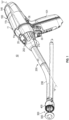
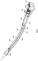
- FIG. 1 illustrates a surgical device, such as, for example, a powered circular stapler 10 for forming end-to-end anastomosis ("EEA"), including a handle assembly 100, which is configured for selective connection with an adapter assembly 200.
- the adapter assembly 200 is configured for selective connection with an end effector 300, which includes a reload 400 and an anvil assembly 500.
- the end effector 300 is configured to produce a surgical effect on tissue of a patient, namely, forming an anastomosis by connecting two portions of a structure (e.g., intestine, colon, etc.) by clamping, stapling, and cutting tissue grasped within the end effector 300.
- a structure e.g., intestine, colon, etc.
- the handle assembly 100 includes a power handle 101 and an outer shell housing 11 configured to selectively receive and encase power handle 101.
- the shell housing 11 includes a distal half-section 11a and a proximal half-section 11b pivotably connected to distal half-section 11a. When joined, distal and proximal half-sections 11a, 11b define a shell cavity therein in which power handle 101 is disposed.
- the powered circular stapler 10 is described herein as a modular device including a plurality of interconnected components, such as the handle assembly 100, the removable shell housing 11, and the adapter assembly 200, etc.
- the powered circular stapler 10 may be formed as an integrated device with one or more of the components being securely attached to each other, e.g., during manufacturing of the powered circular stapler.
- Distal and proximal half-sections 11a, 11b of shell housing 11 are divided along a plane that traverses a longitudinal axis "X" of adapter assembly 200.
- Distal half-section 11a of shell housing 11 defines a connecting portion 20 configured to accept a corresponding drive coupling assembly 210 ( FIG. 3 ) of adapter assembly 200.
- Distal half-section 11a of shell housing 11 supports a toggle control button 30.
- Toggle control button 30 is capable of being actuated in four directions (e.g., a left, right, up, and down).
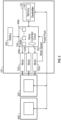
- the power handle 101 includes a main controller circuit board 142, a rechargeable battery 144 configured to supply power to any of the electrical components of handle assembly 100, and a plurality of motors, i.e., a first motor 152a, a second motor 152b, a third motor 152c coupled to the battery 144.
- the power handle 101 also includes a display146.
- the motors 152a, 152b, 152c may be coupled to any suitable power source configured to provide electrical energy to the motors 152a, 152b, 152c, such as an AC/DC transformer.
- Each of the motors 152a, 152b, 152c is coupled a motor controller 143 which controls the operation of the corresponding motors 152a, 152b, 152c including the flow of electrical energy from the battery 144 to the motors 152a, 152b, 152c.
- a main controller 147 is provided that controls the power handle 101.
- the main controller 147 is configured to execute software instructions embodying algorithms disclosed herein, such as clamping, stapling, and cutting algorithms which control operation of the power handle 101.
- the motor controller 143 includes a plurality of sensors 408a ... 408n configured to measure operational states of the motors 152a, 152b, 152c and the battery 144.
- the sensors 408a-n include a strain gauge 408b and may also include voltage sensors, current sensors, temperature sensors, telemetry sensors, optical sensors, and combinations thereof.
- the sensors 408a-408n may measure voltage, current, and other electrical properties of the electrical energy supplied by the battery 144.
- the sensors 408a-408n may also measure angular velocity (e.g., rotational speed) as revolutions per minute (RPM), torque, temperature, current draw, and other operational properties of the motors 152a, 152b, 152c.
- angular velocity e.g., rotational speed
- RPM revolutions per minute
- the sensor 408a also includes an encoder configured to count revolutions or other indicators of the motors 152a, 152b, 152c, which is then use by the main controller 147 to calculate linear movement of components movable by the motors 152a, 152b, 152c.
- Angular velocity may be determined by measuring the rotation of the motors 152a, 152b, 152c or a drive shaft (not shown) coupled thereto and rotatable by the motors 152a, 152b, 152c.
- the position of various axially movable drive shafts may also be determined by using various linear sensors disposed in or in proximity to the shafts or extrapolated from the RPM measurements.
- torque may be calculated based on the regulated current draw of the motors 152a, 152b, 152c at a constant RPM.
- the motor controller 143 and/or the main controller 147 may measure time and process the above-described values as a function of time, including integration and/or differentiation, e.g., to determine the rate of change in the measured values.
- the main controller 147 is also configured to determine distance traveled of various components of the adapter assembly 200 and/or the end effector 300 by counting revolutions of the motors 152a, 152b, 152c.
- the motor controller 143 is coupled to the main controller 147, which includes a plurality of inputs and outputs for interfacing with the motor controller 143.
- the main controller 147 receives measured sensor signals from the motor controller 143 regarding operational status of the motors 152a, 152b, 152c and the battery 144 and, in turn, outputs control signals to the motor controller 143 to control the operation of the motors 152a, 152b, 152c based on the sensor readings and specific algorithm instructions.
- the main controller 147 is also configured to accept a plurality of user inputs from a user interface (e.g., switches, buttons, touch screen, etc. coupled to the main controller 147).
- the main controller 147 is also coupled to a memory 141.
- the memory 141 may include volatile (e.g., RAM) and non-volatile storage configured to store data, including software instructions for operating the power handle 101.
- the main controller 147 is also coupled to the strain gauge 408b of the adapter assembly 200 using a wired or a wireless connection and is configured to receive strain measurements from the strain gauge 408b which are used during operation of the power handle 101.
- the power handle 101 includes a plurality of motors 152a, 152b, 152c each including a respective motor shaft (not explicitly shown) extending therefrom and configured to drive a respective transmission assembly. Rotation of the motor shafts by the respective motors function to drive shafts and/or gear components of adapter assembly 200 in order to perform the various operations of handle assembly 100.
- motors 152a, 152b, 152c of power handle 101 are configured to drive shafts and/or gear components of adapter assembly 200 in order to selectively extend/retract a trocar member 274 ( FIG. 4 ) of a trocar assembly 270 of adapter assembly 200.
- Extension/retraction of the trocar member 274 opens/closes end effector 300 (when anvil assembly 500 is connected to trocar member 274 of trocar assembly 270), fire an annular array of staples 423 of reload 400, and move an annular knife 444 of reload 400.
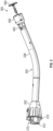
- adapter assembly 200 includes an outer knob housing 202 and an outer tube 206 extending from a distal end of knob housing 202.
- Knob housing 202 and outer tube 206 are configured and dimensioned to house the components of adapter assembly 200.
- the knob housing 202 includes an electrical connector 312 and a storage device 310 coupled thereto.
- the storage device 310 is configured to store various operating parameters pertaining to the adapter assembly 200.
- Adapter assembly 200 is configured to convert rotation of coupling shafts (not explicitly shown) of handle assembly 100 into axial translations useful for operating trocar assembly 270 of adapter assembly 200, anvil assembly 500, and/or staple driver 430 or knife assembly 440 of reload 400.
- Adapter assembly 200 further includes the trocar assembly 270 removably supported in a distal end of outer tube 206.
- Trocar assembly 270 includes a trocar member 274 and a drive screw 276 operably received within trocar member 274 for axially moving trocar member 274 relative to outer tube 206.
- a distal end 274b of trocar member 274 is configured to selectively engage anvil assembly 500, such that axial movement of trocar member 274, via a rotation of drive screw 276, results in a concomitant axial movement of anvil assembly 500.
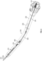
- a clamping transmission assembly 240 includes first rotatable proximal drive shaft 212 coupled to the first motor 152a, a second rotatable proximal drive shaft 281, a rotatable distal drive shaft 282, and a coupling member 286, each of which are supported within the outer tube 206 of adapter assembly 200.
- Clamping transmission assembly 240 functions to extend/retract trocar member 274 of trocar assembly 270 of adapter assembly 200, and to open/close the anvil assembly 510 when anvil assembly 510 is connected to trocar member 274.
- the adapter assembly 200 includes a stapling transmission assembly 250 for interconnecting the second motor 152b and a second axially translatable drive member of reload 400, wherein the stapling transmission assembly 250 converts and transmits a rotation of the second motor 152b to an axial translation of an outer flexible band assembly 255 of adapter assembly 200, and in turn, the staple driver 430 of reload 400 to fire staples 423 from the reload 400 and against anvil assembly 510.
- the stapling transmission assembly 250 of adapter assembly 200 includes the outer flexible band assembly 255 secured to staple driver coupler 254.
- a second rotatable proximal drive shaft 220 is coupled to the second motor 152b and is configured to actuate that staple driver coupler 254, which converts rotational movement into longitudinal movement.
- Outer flexible band assembly 255 includes first and second flexible bands 255a, 255b laterally spaced and connected at proximal ends thereof to a support ring 255c and at distal ends thereof to a proximal end of a distal pusher 255d. Each of first and second flexible bands 255a, 255b is attached to support ring 255c and distal pusher 255d.
- Outer flexible band assembly 255 further includes first and second connection extensions 255e, 255f extending proximally from support ring 255c.
- First and second connection extensions 255e, 255f are configured to operably connect outer flexible band assembly 255 to staple driver coupler 254 of stapling transmission assembly 250.
- the adapter assembly 200 also includes a cutting transmission assembly 260 having a third rotatable proximal drive shaft 222 for interconnecting the third motor 152c and the annular knife 444 of reload 400, wherein the cutting transmission assembly 260 converts and transmits a rotation of one of the third motor 152c to an axial translation of an outer flexible band assembly 265 of adapter assembly 200, and in turn, a knife carrier 442 of reload 400 to advance the annular knife 444 from the reload 400 and against anvil assembly 510.
- a cutting transmission assembly 260 having a third rotatable proximal drive shaft 222 for interconnecting the third motor 152c and the annular knife 444 of reload 400, wherein the cutting transmission assembly 260 converts and transmits a rotation of one of the third motor 152c to an axial translation of an outer flexible band assembly 265 of adapter assembly 200, and in turn, a knife carrier 442 of reload 400 to advance the annular knife 444 from the reload
- Inner flexible band assembly 265 includes first and second flexible bands 265a, 265b laterally spaced and connected at proximal ends thereof to a support ring 265c and at distal ends thereof to a proximal end of a support base 265d. Each of first and second flexible bands 265a, 265b are attached to support ring 265c and support base 265d.
- Inner flexible band assembly 265 further includes first and second connection extensions 265e, 265f extending proximally from support ring 265c.
- First and second connection extensions 265e, 265f are configured to operably connect inner flexible band assembly 265 to knife driver 264 of cutting transmission assembly 260.
- Support base 265d extends distally from flexible bands 265a, 265b and is configured to connect with a knife assembly 440 of reload 400.
- staple driver 430 of reload 400 includes a staple cartridge 420 having a driver adapter 432 and a driver 434.
- a proximal end 432a of driver adapter 432 is configured for selective contact and abutment with distal pusher 255d of outer flexible band assembly 255 of stapling transmission assembly 250 of adapter assembly 200.
- distal pusher 255d of outer flexible band assembly 255 contacts proximal end 432a of driver adapter 432 to advance driver adapter 432 and driver 434 from a first or proximal position to a second or distal position.
- Driver 434 includes a plurality of driver members 436 aligned with staple pockets 421 of staple cartridge 420 for contact with staples 423. Accordingly, advancement of driver 434 relative to staple cartridge 420 causes ejection of the staples 423 from staple cartridge 420.
- the knife assembly 440 of the reload 400 includes a knife carrier 442 and an annular knife 444 secured about a distal end 442b of knife carrier 442.
- a proximal end 442a of knife carrier 442 is configured to engage the support base 265d of inner flexible band assembly.
- support base 265d of inner flexible band assembly 265 connects with proximal end 442a of knife carrier 442 to advance knife carrier 442 and annular knife 444 from a first or proximal position to a second or advanced position to cause the cutting of tissue disposed between staple cartridge 420 and anvil assembly 510.
- Forces during an actuation of trocar member 274, closing of end effector 300 (e.g., a retraction of anvil assembly 500 relative to reload 400), ejecting staples 423 from the reload 400, and advancement of the knife assembly 440 may be measured by the strain gauge 408b in order to monitor and control various processes, such as firing of staples 423 from reload 400; monitor forces during a firing and formation of the staples 423 as the staples 423 are being ejected from reload 400; optimize formation of the staples 423 (e.g., staple crimp height) as the staples 423 are being ejected from reload 400 for different indications of tissue; and monitor and control a firing of the annular knife of reload 400.
- various processes such as firing of staples 423 from reload 400; monitor forces during a firing and formation of the staples 423 as the staples 423 are being ejected from reload 400; optimize formation of the staples 423 (e.g
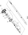
- the anvil assembly 500 includes a head assembly 512 and a center rod assembly 514.
- Head assembly 512 includes a post 516, a housing 518, a cutting ring 522, a cutting ring cover 523, an anvil plate 524, a spacer or washer 525, a cam latch member 526, and a retainer member 527.
- Post 516 is centrally positioned within housing 518.
- the anvil plate 524 is supported in an outer annular recess 528 of an anvil housing 518 and includes a plurality of staple pockets 530 formed therein and configured to receive and form staples.
- the cutting ring 522 includes a central opening which is positioned about a post 516 within an inner annular recess of the housing 518 between post 516 and the outer annular recess 528.
- the cutting ring 522 may be formed from any suitable material, such as a metal or a polymer, e.g., polyethylene.
- a cutting ring cover 523 is also secured to an outwardly facing or proximal surface of the cutting ring 522.
- the retainer member 527 positioned in the inner annular recess between cutting ring 522 and a back wall of housing 518.
- Retainer member 527 may have an annular shape and may include a plurality of deformable tabs which engage a rear surface of cutting ring 522.
- the retainer member 527 prevents the cutting ring 522 from moving or being pushed into the inner annular recess of housing 518 until a predetermined force sufficient to break and/or deform the tabs has been applied to cutting ring 522.
- the annular knife 444 is advanced until the annular knife 444 contacts the cutting ring 522.
- Cam latch member 526 is pivotally mounted within a transverse slot of post 516 of housing 518 and about pivot member 562.
- Cam latch member 526 has an outer cam profile which permits plunger 554 to move forward as cam latch member 526 rotates in a clockwise direction and permits plunger 554 to be retracted as cam latch member 526 rotates in a counterclockwise direction.
- Plunger 554 is slidably positioned in a bore formed in the first end of center rod 552.
- Plunger 554 includes an engagement finger which is offset from the pivot axis of anvil head assembly 512 and biased into engagement with an edge of cam latch 526. Engagement of the finger of plunger 554 with the edge of cam latch 526 presses a leading portion of the edge of cam latch 526 against an inner periphery of cutting ring 522 to urge anvil head assembly 512 to an operative or non-tilted position on center rod 552.
- Anvil head assembly 512 may be tilted relative to anvil center rod assembly 514 in a pre-fired tilted position. Tilting of anvil head assembly 512 relative to anvil center rod assembly 514 causes the body portion of cam latch member 526 to engage a finger of plunger 554. As cam latch member 526 rotates with the tilting of anvil head assembly 512, plunger 554 is retracted with the bore of anvil center rod assembly 514, thereby compressing spring 556. In this manner, finger 566 of plunger 554 is distally biased against the body portion of cam latch member 526.
- the cam latch member 526 is also configured to engage the retainer member 527 via a finger. Once engaged, the cam latch member 526 maintains the anvil head assembly 512 in the non-tilted position. As the retainer member 527 is deformed or broken by the cutting ring 522, the cam latch member 526 also disengages from the anvil head assembly 512, which allows the anvil head assembly 512 to tilt to the pre-fired tilted position during unclamping.
- U.S. Patent No. US9554802 filed on November 13, 2013 , the entire contents of which being incorporated by reference herein.
- the strain gauge 408b of adapter assembly 200 is disposed within a strain gauge housing 320.
- the strain gauge 408b measures and monitors the retraction of trocar member 274 as well as the ejection and formation of the staples 423 from the reload 400.
- a reaction force is exerted on anvil assembly 500 which is in a generally distal direction. This distally directed reaction force is communicated from anvil assembly 500 to the strain gauge 408b.
- the strain gauge 408b then communicates signals to main controller circuit board 142 of power handle 101 of handle assembly 100. Graphics ( FIG. 8 ) are then displayed on the display 146 of handle assembly 100 to provide the user with real-time information related to the status of the firing of handle assembly 100.
- the trocar assembly 270 is axially and rotationally fixed within outer tube 206 of adapter assembly 200.
- adapter assembly 200 includes a support block 292 fixedly disposed within outer tube 206.
- the strain gauge housing 320 is disposed between the support block 292 and a connector sleeve 290.
- the reload 400 is removably coupled to the connector sleeve 290.
- strain gauge 408b of adapter assembly 200 measures and monitors the retraction of trocar member 274, which passes through the strain gauge 408b.
- the strain gauge 408b of adapter assembly 200 also measures and monitors ejection of the staples 423 from the reload 400, since the first and second flexible bands 2fthir55a, 255b also pass through the strain gauge 408b.
- a reaction force is exerted on anvil assembly 500 and the reload 400, which is communicated to support block 292, which then communicates the reaction force to a strain sensor of the strain gauge 408b.
- Strain sensor of strain gauge 408b may be any device configured to measure strain (a dimensionless quantity) on an object that it is adhered to (e.g., support block 292), such that, as the object deforms, a metallic foil of the strain sensor is also deformed, causing an electrical resistance thereof to change, which change in resistance is then used to calculate loads experienced by trocar assembly 270.
- Strain gauge 408b provides closed-loop feedback to a firing/clamping load exhibited by first, second and third force/rotation transmitting/converting assemblies.
- Strain sensor of strain gauge 408b then communicates signals to main controller circuit board 142. Graphics are then displayed on display 146 of power-pack core assembly 106 of handle assembly 100 to provide the user with real-time information related to the status of the firing of handle assembly 100. Strain gauge 408b is also electrically connected to the electrical connector 312 ( FIG. 3 ) via proximal and distal harness assemblies 314, 316.
- the reload 400 includes a storage device 402 and the circular adapter assembly 200 also includes a storage device 310 ( FIG. 4 ).
- the storage devices 402 and 310 include non-volatile storage medium (e.g., EEPROM) that is configured to store any data pertaining to the reload 400 and the circular adapter assembly 200, respectively, including but not limited to, usage count, identification information, model number, serial number, staple size, stroke length, maximum actuation force, minimum actuation force, factory calibration data, and the like.
- the data may be encrypted and is only decryptable by devices (e.g., main controller 147) having appropriate keys.
- the data may also be used by the main controller 147 to authenticate the circular adapter assembly 200 and/or the reload 400.
- the storage devices 402 and 310 may be configured in read only or read/write modes, allowing the main controller 147 to read as well as write data onto the storage device 402 and 310.
- the power handle 101 Prior to operation of the powered circular stapler 10, the power handle 101 is enclosed within the shell housing 11 the adapter assembly 200 is coupled to handle assembly 100.
- handle assembly 100 After attachment of circular adapter assembly 200, handle assembly 100 initially verifies that circular adapter assembly 200 is coupled thereto by establishing communications with the storage device 310 of the circular adapter assembly 200 and authenticates circular adapter assembly 200.
- the data (e.g., usage count) stored on the storage device 310 is encrypted and is authenticated by the power handle 101 prior to determining whether the usage count stored on the storage device 310 exceeds the threshold (e.g., if the adapter assembly 200 has been previously used).
- Power handle 101 then performs verification checks (e.g., end of life checks, trocar member 274 missing, etc.) and calibrates circular adapter assembly 200 after the handle assembly 100 confirms that the trocar member 274 is attached.
- the user commences a surgical procedure by positioning the adapter assembly 200, including the trocar member 274 and the anvil assembly 510, within the colorectal or upper gastrointestinal region.
- the user presses the toggle control button 30 to extend the trocar member 274 until it pierces tissue.
- the anvil assembly 510 that was previously positioned by surgeon is attached to the trocar member 274 and the user begins the clamping process on the tissue interposed between reload 400 and the anvil assembly 510 by pressing on the bottom portion of the toggle control button 30.
- the clamping process may include controlled tissue compression until a desired threshold is reached. Once tissue is compressed, the user may initial the stapling process by pressing the toggle control button 30. In embodiments, the stapling process may be commenced automatically once tissue compression is confirmed by the main controller 147. After stapling is completed, which may be also monitored by the main controller 147, the cutting process may be initiated automatically or by pressing the toggle control button 30.
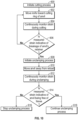
- FIG. 9 shows a flow chart of a method for determining whether the anvil assembly 500 is released from the anastomosis.
- the method includes initiating the cutting process at step 600 by pressing the toggle control button 30 and/or automatically based on determination that the stapling process is complete by the main controller 147, e.g., based on strain, distance, and/or time measurements.
- the third motor 152c moves the outer flexible band assembly 265 of adapter assembly 200, and in turn, advances the annular knife 444 from the reload 400 until the annular knife 444 contacts the cutting ring 522.
- the strain on the outer flexible band assembly 265 is measured by the strain gauge 408b. The measured strain is compared at step 606 to strain threshold and/or strain patterns indicative of the retaining member, e.g., a sudden drop in strain. If the strain measurement does not correspond to the completion of the cutting process, the method continues moving the annular knife 444. In addition, the method may also include outputting an error the display 146, e.g., if a timeout occurs and the strain does not indicate completion.
- step 608 the unclamping process is initiated, by pressing the toggle control button 30 and/or automatically based on determination that the cutting process is complete by the main controller 147, e.g., based on strain, distance, and/or time measurements.
- the first motor 152a actuates the clamping transmission assembly 240 to move the anvil assembly 500 in the distal direction and away from the reload 400.
- the strain on the clamping transmission assembly 240 is measured by the strain gauge 408b. The measured strain is compared at step 614 to strain threshold and/or patterns indicative of the anvil assembly 500 being attached to the tissue, e.g., strain exceeding threshold of a freely movable anvil assembly 500. If the strain measurement does not indicate that the anvil assembly 500 is free of the anastomosis, at step 616, the main controller 147 may stop the unclamping process and/or output an error the display 146.
- the error may be displayed if a timeout occurs, and the strain indicates that the anvil assembly 500 is adhering to anastomosis or is otherwise not movable. If the strain is indicative of the anvil assembly 500 being free and movable, then the at step 618, the unclamping process continues until it is complete.
- the display 146 may also output progress bars and other indicia representative of each of the clamping, unclamping, stapling, and cutting processes.
- the described techniques may be implemented in hardware, software, firmware, or any combination thereof. If implemented in software, the functions may be stored as one or more instructions or code on a computer-readable medium and executed by a hardware-based processing unit.
- Computer-readable media may include non-transitory computer-readable media, which corresponds to a tangible medium such as data storage media (e.g., RAM, ROM, EEPROM, flash memory, or any other medium that can be used to store desired program code in the form of instructions or data structures and that can be accessed by a computer).
- processors such as one or more digital signal processors (DSPs), general purpose microprocessors, application specific integrated circuits (ASICs), field programmable logic arrays (FPGAs), or other equivalent integrated or discrete logic circuitry.
- DSPs digital signal processors
- ASICs application specific integrated circuits
- FPGAs field programmable logic arrays
- processors may refer to any of the foregoing structure or any other physical structure suitable for implementation of the described techniques. Also, the techniques could be fully implemented in one or more circuits or logic elements.
Landscapes
- Health & Medical Sciences (AREA)
- Life Sciences & Earth Sciences (AREA)
- Surgery (AREA)
- Heart & Thoracic Surgery (AREA)
- Engineering & Computer Science (AREA)
- Biomedical Technology (AREA)
- Nuclear Medicine, Radiotherapy & Molecular Imaging (AREA)
- Medical Informatics (AREA)
- Molecular Biology (AREA)
- Animal Behavior & Ethology (AREA)
- General Health & Medical Sciences (AREA)
- Public Health (AREA)
- Veterinary Medicine (AREA)
- Surgical Instruments (AREA)
Abstract
Description
- The present disclosure relates to surgical devices. More specifically, the present disclosure relates to handheld electromechanical surgical systems for performing surgical procedures.
- Circular staplers are used in a surgical procedure to reattach rectum portions that were previously transected, or similar procedures. Circular clamping, cutting and stapling instruments may be manually actuated and may include a pistol or linear grip-styled structure having an elongated shaft extending therefrom and a staple cartridge supported on the distal end of the elongated shaft. A physician may insert an anvil assembly of the circular stapling instrument through an incision and toward the transected rectum portions. The physician may also insert the remainder of the circular stapling instrument (including the cartridge assembly) into a rectum of a patient and maneuver the instrument up the colonic tract of the patient toward the transected rectum portions. The anvil and cartridge assemblies are approximated toward one another, and staples are ejected from the cartridge assembly toward the anvil assembly to form the staples in tissue to affect an end-to-end anastomosis, and an annular knife is advanced to core a portion of the clamped tissue portions. After the end-to-end anastomosis has been affected, the circular stapling apparatus is removed from the surgical site. Powered surgical staplers have also been developed and utilize one or more motors to clamp, cut, and staple tissue.
- In certain cases, with manual and powered circular staplers, the anvil may not fully release from the anastomosis during anvil extraction. This may threaten the integrity of anastomosis as tension of stress on the tissue may affect the tissue health or staple line integrity. Therefore, surgeons must currently closely monitor removal forces and remove the device slowly and with care, occasionally manipulating the device to ensure the anvil is released from the anastomosis.
- The present disclosure provides a powered circular stapler that is configured to operate in three sequences, namely, clamping, stapling, and cutting to form an anastomosis by connecting two portions of a structure (e.g., intestine, colon, etc.). The powered circular stapler includes a handle assembly having a power source and one or more motors coupled to the power source. The stapler also includes an adapter assembly having multiple transmission assemblies, e.g., drive shafts, which transmit actuation from the powered handle. The powered handle assembly and the adapter assembly may be reusable.
- The powered surgical staplers operate in four phases, namely, clamping, stapling, cutting, and unclamping. Clamping is accomplished by moving the anvil in a proximal direction to compress tissue between the anvil and a reload assembly, which includes a plurality of staples. The anvil and the reload assembly may be disposable. During stapling, the staples are ejected from the reload assembly into the clamped tissue and are deformed against the anvil. Cutting includes moving an annular knife through the compressed and stapled tissue until the knife contacts the anvil. During unclamping, the anvil assembly is moved distally away from the cut tissue and the reload assembly.
- The anvil includes a breakable retainer configured to secure a cutting ring, i.e., the surface that contact the annular knife, inside a tiltable anvil head of the anvil assembly. Upon breaking of the retainer member, the cutting ring is pushed into the anvil. In addition, the breakage of the retainer also allows the anvil head to tilt, such that as the anvil is moved away from the reload, the anvil head is released from the tissue and is tilted.
- Each of the clamping, stapling, cutting, and unclamping phases may be monitored to ensure proper operation of the powered surgical stapler, including proper anvil release after the cutting process is complete. The powered surgical stapler also includes a sensor, e.g., a strain gauge, configured to measure forces during each of the processes, and a controller configured to monitor the forces and detect any abnormalities during operation of the powered surgical stapler. In particular, the controller is configured to monitor forces during unclamping and identify any unexpected forces on the anvil assembly. If such forces are detected, this may be due to the anvil not being released from the anastomosis. Thus, the controller may pause and/or terminate the unclamping process to prevent any damage to the powered surgical stapler and/or injury to the anastomosis. The controller may be also configured to alert the user to intervene, e.g., manually release the anvil assembly, in the unclamping process.
- According to one embodiment of the present disclosure, a surgical device is disclosed. The surgical device includes a reload assembly having a plurality of staples and an anvil assembly movable relative to the reload assembly. The device also includes a power source and a motor coupled to the power source. The device further includes a transmission assembly movable by the motor and configured to move the anvil assembly relative to the reload assembly. The device additionally includes a strain sensor configured to measure strain imparted on the transmission assembly. The device also includes a controller configured to determine whether the anvil assembly is adhered to tissue grasped between the reload assembly and the anvil assembly based on the measured strain.
- Implementations of the above embodiment may include one or more of the following features. According to one aspect of the above embodiment, the anvil assembly may include: a rod; an anvil head pivotable from a tilt position to a non-tilt position relative to the rod; and a retainer is configured to maintain the anvil head in the non-tilt position. The anvil assembly may further include a cutting ring coupled to the retainer. The cutting ring may be configured to at least one of deform or break the retainer. The controller may be further configured to determine that the anvil assembly is tilted based on a change in measured strain indicative of at least one of deformation or breakage of the retainer. The controller may be also configured to determine whether the anvil assembly is movable during unclamping. The surgical device may also include a longitudinal shaft enclosing the transmission assembly. The strain sensor may be disposed in the longitudinal shaft and contacts the transmission assembly.
- According to another embodiment of the present disclosure, a surgical device is disclosed. The surgical device includes a reload assembly having a plurality of staples and an anvil assembly movable relative to the reload assembly. The device also includes a power source, a first motor coupled to the power source, and a first transmission assembly movable by the first motor and configured to move the anvil assembly relative to the reload assembly. The device further includes a second motor coupled to the power source, a second transmission assembly movable by the second motor and configured to move a knife assembly to cut tissue grasped between the reload assembly and the anvil assembly. The device additionally includes a strain sensor configured to measure strain imparted on the first transmission assembly and the second transmission assembly. The device further includes a controller configured to determine whether the anvil assembly is adhered to the tissue based on the measured strain.
- Implementations of the above embodiment may include one or more of the following features. According to one aspect of the above embodiment, the anvil assembly may include: a rod; an anvil head pivotable from a tilt position to a non-tilt position relative to the rod; and a retainer is configured to maintain the anvil head in the non-tilt position. The anvil assembly may further include a cutting ring coupled to the retainer and to contact the knife. The cutting ring may be configured to at least one of deform or break the retainer. The controller may be further configured to determine the anvil assembly is tilted based on a change in measured strain indicative of at least one of deformation or breakage of the retainer. The controller may be also configured to determine whether the anvil assembly is movable during unclamping. The surgical device may also include a longitudinal shaft enclosing at least a portion of each of the first transmission assembly and the second transmission assembly. The strain sensor may be disposed in the longitudinal shaft and contact the first transmission assembly and the second transmission assembly.
- According to a further embodiment of the present disclosure, a method for controlling a powered surgical stapler is disclosed. The method includes activating a first motor to move a first transmission assembly coupled to an anvil assembly that is movable relative to a reload assembly having a plurality of staples. The method also includes activating a second motor to move a second transmission assembly coupled to a knife assembly configured to cut tissue grasped between the reload assembly and the anvil assembly. The method further includes measuring through a strain sensor, strain imparted on the first transmission assembly and the second transmission assembly. The method additionally includes determining, at a controller, whether the anvil assembly is adhered to the tissue based on the measured strain.
- Implementations of the above embodiment may include one or more of the following features. According to one aspect of the above embodiment, the method may also include pivoting an anvil head of the anvil assembly and securing the anvil head in a non-tilted position using a retainer. The method further includes determining, at the controller, that the anvil assembly is tiltable based on a change in measured strain indicative of at least one of deformation or breakage of the retainer. The method also includes determining, at the controller, whether the anvil assembly is movable during unclamping.
- Embodiments of the present disclosure are described herein with reference to the accompanying drawings, wherein:
-
FIG. 1 is a perspective view of a powered circular stapler including a handle assembly, an adapter assembly, and an end effector, according to an embodiment of the present disclosure; -
FIG. 2 is a schematic diagram of the handle assembly, the adapter assembly, and the end effector ofFIG. 1 ; -
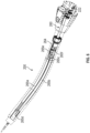
FIG. 3 is a side perspective view of the adapter assembly and the end effector, an annular reload and an anvil assembly, attached to the adapter assembly ofFIG. 1 according to an embodiment of the present disclosure; -
FIG. 4 is a perspective view of a clamping transmission assembly disposed within the adapter assembly ofFIG. 1 , shown partially in phantom; -
FIG. 5 is a perspective view of a stapling transmission assembly disposed within the adapter assembly ofFIG. 1 , shown partially in phantom; -
FIG. 6 is a perspective view of a cutting transmission assembly disposed within the adapter assembly ofFIG. 1 , shown partially in phantom; -
FIG. 7 is a cross-sectional view of a reload of the end effector ofFIG. 1 ; -
FIG. 8 is a perspective view, with parts separated, of the anvil assembly ofFIG. 1 ; -
FIG. 9 is a perspective view of the adapter assembly, shown partially disassembled, with a strain gauge assembly; and -
FIG. 10 is a flow chart of a method for determining anvil release during an anastomosis procedure according to an embodiment of the present disclosure. - Embodiments of the presently disclosed surgical devices, and adapter assemblies for surgical devices and/or handle assemblies are described in detail with reference to the drawings, in which like reference numerals designate identical or corresponding elements in each of the several views. As used herein the term "distal" refers to that portion of the surgical instrument, or component thereof, farther from the user, while the term "proximal" refers to that portion of the surgical instrument, or component thereof, closer to the user.
- The present disclosure provides a powered
circular stapler 10 having a handle assembly, an adapter assembly coupled to the handle assembly, and an end effector coupled to the adapter assembly. The stapler allows for full, independent control of three functions: clamping, stapling, and cutting. This allows certain portions of the stapler to adapt if the tissue presents a non-ideal situation. -
FIG. 1 illustrates a surgical device, such as, for example, a poweredcircular stapler 10 for forming end-to-end anastomosis ("EEA"), including ahandle assembly 100, which is configured for selective connection with anadapter assembly 200. Theadapter assembly 200 is configured for selective connection with anend effector 300, which includes a reload 400 and ananvil assembly 500. Theend effector 300 is configured to produce a surgical effect on tissue of a patient, namely, forming an anastomosis by connecting two portions of a structure (e.g., intestine, colon, etc.) by clamping, stapling, and cutting tissue grasped within theend effector 300. - The
handle assembly 100 includes apower handle 101 and anouter shell housing 11 configured to selectively receive and encasepower handle 101. Theshell housing 11 includes a distal half-section 11a and a proximal half-section 11b pivotably connected to distal half-section 11a. When joined, distal and proximal half-sections - While the powered
circular stapler 10 is described herein as a modular device including a plurality of interconnected components, such as thehandle assembly 100, theremovable shell housing 11, and theadapter assembly 200, etc. The poweredcircular stapler 10 may be formed as an integrated device with one or more of the components being securely attached to each other, e.g., during manufacturing of the powered circular stapler. - Distal and proximal half-
sections shell housing 11 are divided along a plane that traverses a longitudinal axis "X" ofadapter assembly 200. Distal half-section 11a ofshell housing 11 defines a connectingportion 20 configured to accept a corresponding drive coupling assembly 210 (FIG. 3 ) ofadapter assembly 200. Distal half-section 11a ofshell housing 11 supports atoggle control button 30.Toggle control button 30 is capable of being actuated in four directions (e.g., a left, right, up, and down). - With reference to
FIGS. 1 and2 , thepower handle 101 includes a maincontroller circuit board 142, arechargeable battery 144 configured to supply power to any of the electrical components ofhandle assembly 100, and a plurality of motors, i.e., afirst motor 152a, a second motor 152b, athird motor 152c coupled to thebattery 144. Thepower handle 101 also includes a display146. In embodiments, themotors motors motors motor controller 143 which controls the operation of the correspondingmotors battery 144 to themotors main controller 147 is provided that controls thepower handle 101. Themain controller 147 is configured to execute software instructions embodying algorithms disclosed herein, such as clamping, stapling, and cutting algorithms which control operation of thepower handle 101. - The
motor controller 143 includes a plurality ofsensors 408a ... 408n configured to measure operational states of themotors battery 144. Thesensors 408a-n include astrain gauge 408b and may also include voltage sensors, current sensors, temperature sensors, telemetry sensors, optical sensors, and combinations thereof. Thesensors 408a-408n may measure voltage, current, and other electrical properties of the electrical energy supplied by thebattery 144. Thesensors 408a-408n may also measure angular velocity (e.g., rotational speed) as revolutions per minute (RPM), torque, temperature, current draw, and other operational properties of themotors sensor 408a also includes an encoder configured to count revolutions or other indicators of themotors main controller 147 to calculate linear movement of components movable by themotors motors motors motors motor controller 143 and/or themain controller 147 may measure time and process the above-described values as a function of time, including integration and/or differentiation, e.g., to determine the rate of change in the measured values. Themain controller 147 is also configured to determine distance traveled of various components of theadapter assembly 200 and/or theend effector 300 by counting revolutions of themotors - The
motor controller 143 is coupled to themain controller 147, which includes a plurality of inputs and outputs for interfacing with themotor controller 143. In particular, themain controller 147 receives measured sensor signals from themotor controller 143 regarding operational status of themotors battery 144 and, in turn, outputs control signals to themotor controller 143 to control the operation of themotors main controller 147 is also configured to accept a plurality of user inputs from a user interface (e.g., switches, buttons, touch screen, etc. coupled to the main controller 147). - The
main controller 147 is also coupled to amemory 141. Thememory 141 may include volatile (e.g., RAM) and non-volatile storage configured to store data, including software instructions for operating thepower handle 101. Themain controller 147 is also coupled to thestrain gauge 408b of theadapter assembly 200 using a wired or a wireless connection and is configured to receive strain measurements from thestrain gauge 408b which are used during operation of thepower handle 101. - The
power handle 101 includes a plurality ofmotors adapter assembly 200 in order to perform the various operations ofhandle assembly 100. In particular,motors power handle 101 are configured to drive shafts and/or gear components ofadapter assembly 200 in order to selectively extend/retract a trocar member 274 (FIG. 4 ) of atrocar assembly 270 ofadapter assembly 200. Extension/retraction of thetrocar member 274 opens/closes end effector 300 (whenanvil assembly 500 is connected totrocar member 274 of trocar assembly 270), fire an annular array ofstaples 423 of reload 400, and move anannular knife 444 of reload 400. - Turning now to
FIGS. 3 and4 ,adapter assembly 200 includes anouter knob housing 202 and anouter tube 206 extending from a distal end ofknob housing 202.Knob housing 202 andouter tube 206 are configured and dimensioned to house the components ofadapter assembly 200. Theknob housing 202 includes anelectrical connector 312 and astorage device 310 coupled thereto. Thestorage device 310 is configured to store various operating parameters pertaining to theadapter assembly 200.Adapter assembly 200 is configured to convert rotation of coupling shafts (not explicitly shown) ofhandle assembly 100 into axial translations useful for operatingtrocar assembly 270 ofadapter assembly 200,anvil assembly 500, and/orstaple driver 430 orknife assembly 440 of reload 400. -
Adapter assembly 200 further includes thetrocar assembly 270 removably supported in a distal end ofouter tube 206.Trocar assembly 270 includes atrocar member 274 and adrive screw 276 operably received withintrocar member 274 for axially movingtrocar member 274 relative toouter tube 206. Adistal end 274b oftrocar member 274 is configured to selectively engageanvil assembly 500, such that axial movement oftrocar member 274, via a rotation ofdrive screw 276, results in a concomitant axial movement ofanvil assembly 500. - With reference to
FIG. 4 , a clampingtransmission assembly 240 includes first rotatableproximal drive shaft 212 coupled to thefirst motor 152a, a second rotatableproximal drive shaft 281, a rotatabledistal drive shaft 282, and acoupling member 286, each of which are supported within theouter tube 206 ofadapter assembly 200. Clampingtransmission assembly 240 functions to extend/retracttrocar member 274 oftrocar assembly 270 ofadapter assembly 200, and to open/close the anvil assembly 510 when anvil assembly 510 is connected totrocar member 274. - With reference to
FIG. 5 , theadapter assembly 200 includes a staplingtransmission assembly 250 for interconnecting the second motor 152b and a second axially translatable drive member of reload 400, wherein the staplingtransmission assembly 250 converts and transmits a rotation of the second motor 152b to an axial translation of an outerflexible band assembly 255 ofadapter assembly 200, and in turn, thestaple driver 430 of reload 400 to firestaples 423 from the reload 400 and against anvil assembly 510. - The stapling
transmission assembly 250 ofadapter assembly 200 includes the outerflexible band assembly 255 secured to stapledriver coupler 254. A second rotatableproximal drive shaft 220 is coupled to the second motor 152b and is configured to actuate thatstaple driver coupler 254, which converts rotational movement into longitudinal movement. Outerflexible band assembly 255 includes first and secondflexible bands support ring 255c and at distal ends thereof to a proximal end of adistal pusher 255d. Each of first and secondflexible bands ring 255c anddistal pusher 255d. Outerflexible band assembly 255 further includes first andsecond connection extensions support ring 255c. First andsecond connection extensions flexible band assembly 255 tostaple driver coupler 254 of staplingtransmission assembly 250. - With reference to
FIG. 6 , theadapter assembly 200 also includes a cuttingtransmission assembly 260 having a third rotatableproximal drive shaft 222 for interconnecting thethird motor 152c and theannular knife 444 of reload 400, wherein the cuttingtransmission assembly 260 converts and transmits a rotation of one of thethird motor 152c to an axial translation of an outer flexible band assembly 265 ofadapter assembly 200, and in turn, aknife carrier 442 of reload 400 to advance theannular knife 444 from the reload 400 and against anvil assembly 510. - Inner flexible band assembly 265 includes first and second
flexible bands support ring 265c and at distal ends thereof to a proximal end of asupport base 265d. Each of first and secondflexible bands ring 265c andsupport base 265d. - Inner flexible band assembly 265 further includes first and
second connection extensions support ring 265c. First andsecond connection extensions knife driver 264 of cuttingtransmission assembly 260.Support base 265d extends distally fromflexible bands knife assembly 440 of reload 400. - With reference to
FIG. 7 ,staple driver 430 of reload 400 includes astaple cartridge 420 having adriver adapter 432 and adriver 434. Aproximal end 432a ofdriver adapter 432 is configured for selective contact and abutment withdistal pusher 255d of outerflexible band assembly 255 of staplingtransmission assembly 250 ofadapter assembly 200. In operation, during distal advancement of outerflexible band assembly 255, as described above,distal pusher 255d of outerflexible band assembly 255 contactsproximal end 432a ofdriver adapter 432 to advancedriver adapter 432 anddriver 434 from a first or proximal position to a second or distal position.Driver 434 includes a plurality ofdriver members 436 aligned withstaple pockets 421 ofstaple cartridge 420 for contact withstaples 423. Accordingly, advancement ofdriver 434 relative tostaple cartridge 420 causes ejection of thestaples 423 fromstaple cartridge 420. - The
knife assembly 440 of the reload 400 includes aknife carrier 442 and anannular knife 444 secured about adistal end 442b ofknife carrier 442. Aproximal end 442a ofknife carrier 442 is configured to engage thesupport base 265d of inner flexible band assembly. In operation, during distal advancement of inner flexible band assembly 265,support base 265d of inner flexible band assembly 265 connects withproximal end 442a ofknife carrier 442 to advanceknife carrier 442 andannular knife 444 from a first or proximal position to a second or advanced position to cause the cutting of tissue disposed betweenstaple cartridge 420 and anvil assembly 510. - Forces during an actuation of
trocar member 274, closing of end effector 300 (e.g., a retraction ofanvil assembly 500 relative to reload 400), ejectingstaples 423 from the reload 400, and advancement of theknife assembly 440 may be measured by thestrain gauge 408b in order to monitor and control various processes, such as firing ofstaples 423 from reload 400; monitor forces during a firing and formation of thestaples 423 as thestaples 423 are being ejected from reload 400; optimize formation of the staples 423 (e.g., staple crimp height) as thestaples 423 are being ejected from reload 400 for different indications of tissue; and monitor and control a firing of the annular knife of reload 400. - With reference
FIG. 8 , theanvil assembly 500 includes ahead assembly 512 and acenter rod assembly 514.Head assembly 512 includes apost 516, ahousing 518, acutting ring 522, a cuttingring cover 523, ananvil plate 524, a spacer orwasher 525, acam latch member 526, and aretainer member 527.Post 516 is centrally positioned withinhousing 518. Theanvil plate 524 is supported in an outer annular recess 528 of ananvil housing 518 and includes a plurality of staple pockets 530 formed therein and configured to receive and form staples. - The cutting
ring 522 includes a central opening which is positioned about apost 516 within an inner annular recess of thehousing 518 betweenpost 516 and the outer annular recess 528. The cuttingring 522 may be formed from any suitable material, such as a metal or a polymer, e.g., polyethylene. A cuttingring cover 523 is also secured to an outwardly facing or proximal surface of thecutting ring 522. - The
retainer member 527 positioned in the inner annular recess between cuttingring 522 and a back wall ofhousing 518.Retainer member 527 may have an annular shape and may include a plurality of deformable tabs which engage a rear surface of cuttingring 522. Theretainer member 527 prevents thecutting ring 522 from moving or being pushed into the inner annular recess ofhousing 518 until a predetermined force sufficient to break and/or deform the tabs has been applied to cuttingring 522. During cutting of tissue theannular knife 444 is advanced until theannular knife 444 contacts thecutting ring 522. Continuous pressure by theannular knife 444 on thecutting ring 522 results in breakage of theretainer member 527, which allows thecutting ring 522 to move into thehousing 518 and separate from the tissue. This allows for separation of theanvil assembly 500 from the tissue and facilitates the unclamping process. -
Cam latch member 526 is pivotally mounted within a transverse slot ofpost 516 ofhousing 518 and aboutpivot member 562.Cam latch member 526 has an outer cam profile which permitsplunger 554 to move forward ascam latch member 526 rotates in a clockwise direction and permitsplunger 554 to be retracted ascam latch member 526 rotates in a counterclockwise direction. -
Plunger 554 is slidably positioned in a bore formed in the first end ofcenter rod 552.Plunger 554 includes an engagement finger which is offset from the pivot axis ofanvil head assembly 512 and biased into engagement with an edge ofcam latch 526. Engagement of the finger ofplunger 554 with the edge ofcam latch 526 presses a leading portion of the edge ofcam latch 526 against an inner periphery of cuttingring 522 to urgeanvil head assembly 512 to an operative or non-tilted position oncenter rod 552. -
Anvil head assembly 512 may be tilted relative to anvilcenter rod assembly 514 in a pre-fired tilted position. Tilting ofanvil head assembly 512 relative to anvilcenter rod assembly 514 causes the body portion ofcam latch member 526 to engage a finger ofplunger 554. Ascam latch member 526 rotates with the tilting ofanvil head assembly 512,plunger 554 is retracted with the bore of anvilcenter rod assembly 514, thereby compressingspring 556. In this manner, finger 566 ofplunger 554 is distally biased against the body portion ofcam latch member 526. - The
cam latch member 526 is also configured to engage theretainer member 527 via a finger. Once engaged, thecam latch member 526 maintains theanvil head assembly 512 in the non-tilted position. As theretainer member 527 is deformed or broken by the cuttingring 522, thecam latch member 526 also disengages from theanvil head assembly 512, which allows theanvil head assembly 512 to tilt to the pre-fired tilted position during unclamping. For further details regarding the construction and operation of the anvil assembly, reference may be made to U.S. Patent No.US9554802, filed on November 13, 2013 - With reference to
FIG. 9 , thestrain gauge 408b ofadapter assembly 200 is disposed within astrain gauge housing 320. Thestrain gauge 408b measures and monitors the retraction oftrocar member 274 as well as the ejection and formation of thestaples 423 from the reload 400. During the closing ofend effector 300, whenanvil assembly 500 contacts tissue, an obstruction, a tissue-contacting surface of the reload 400, staple ejection, or the like, a reaction force is exerted onanvil assembly 500 which is in a generally distal direction. This distally directed reaction force is communicated fromanvil assembly 500 to thestrain gauge 408b. Thestrain gauge 408b then communicates signals to maincontroller circuit board 142 of power handle 101 ofhandle assembly 100. Graphics (FIG. 8 ) are then displayed on thedisplay 146 ofhandle assembly 100 to provide the user with real-time information related to the status of the firing ofhandle assembly 100. - The
trocar assembly 270 is axially and rotationally fixed withinouter tube 206 ofadapter assembly 200. With reference toFIG. 8 ,adapter assembly 200 includes asupport block 292 fixedly disposed withinouter tube 206. Thestrain gauge housing 320 is disposed between thesupport block 292 and aconnector sleeve 290. The reload 400 is removably coupled to theconnector sleeve 290. - In operation,
strain gauge 408b ofadapter assembly 200 measures and monitors the retraction oftrocar member 274, which passes through thestrain gauge 408b. Thestrain gauge 408b ofadapter assembly 200 also measures and monitors ejection of thestaples 423 from the reload 400, since the first and second flexible bands 2fthir55a, 255b also pass through thestrain gauge 408b. During clamping, stapling, and cutting, a reaction force is exerted onanvil assembly 500 and the reload 400, which is communicated to supportblock 292, which then communicates the reaction force to a strain sensor of thestrain gauge 408b. - Strain sensor of
strain gauge 408b may be any device configured to measure strain (a dimensionless quantity) on an object that it is adhered to (e.g., support block 292), such that, as the object deforms, a metallic foil of the strain sensor is also deformed, causing an electrical resistance thereof to change, which change in resistance is then used to calculate loads experienced bytrocar assembly 270.Strain gauge 408b provides closed-loop feedback to a firing/clamping load exhibited by first, second and third force/rotation transmitting/converting assemblies. - Strain sensor of
strain gauge 408b then communicates signals to maincontroller circuit board 142. Graphics are then displayed ondisplay 146 of power-pack core assembly 106 ofhandle assembly 100 to provide the user with real-time information related to the status of the firing ofhandle assembly 100.Strain gauge 408b is also electrically connected to the electrical connector 312 (FIG. 3 ) via proximal anddistal harness assemblies - For further details regarding the construction and operation of the circular stapler and its components, reference may be made to International Application Publication No.
PCT/US2019/040440, filed on July 3, 2019 , the entire contents of which being incorporated by reference herein. - The reload 400 includes a
storage device 402 and thecircular adapter assembly 200 also includes a storage device 310 (FIG. 4 ). Thestorage devices circular adapter assembly 200, respectively, including but not limited to, usage count, identification information, model number, serial number, staple size, stroke length, maximum actuation force, minimum actuation force, factory calibration data, and the like. In embodiments, the data may be encrypted and is only decryptable by devices (e.g., main controller 147) having appropriate keys. The data may also be used by themain controller 147 to authenticate thecircular adapter assembly 200 and/or the reload 400. Thestorage devices main controller 147 to read as well as write data onto thestorage device - Prior to operation of the powered
circular stapler 10, thepower handle 101 is enclosed within theshell housing 11 theadapter assembly 200 is coupled to handleassembly 100. After attachment ofcircular adapter assembly 200, handleassembly 100 initially verifies thatcircular adapter assembly 200 is coupled thereto by establishing communications with thestorage device 310 of thecircular adapter assembly 200 and authenticatescircular adapter assembly 200. The data (e.g., usage count) stored on thestorage device 310 is encrypted and is authenticated by thepower handle 101 prior to determining whether the usage count stored on thestorage device 310 exceeds the threshold (e.g., if theadapter assembly 200 has been previously used). Power handle 101 then performs verification checks (e.g., end of life checks,trocar member 274 missing, etc.) and calibratescircular adapter assembly 200 after thehandle assembly 100 confirms that thetrocar member 274 is attached. - The user commences a surgical procedure by positioning the
adapter assembly 200, including thetrocar member 274 and the anvil assembly 510, within the colorectal or upper gastrointestinal region. The user presses thetoggle control button 30 to extend thetrocar member 274 until it pierces tissue. After extension of thetrocar member 274, the anvil assembly 510 that was previously positioned by surgeon is attached to thetrocar member 274 and the user begins the clamping process on the tissue interposed between reload 400 and the anvil assembly 510 by pressing on the bottom portion of thetoggle control button 30. - The clamping process may include controlled tissue compression until a desired threshold is reached. Once tissue is compressed, the user may initial the stapling process by pressing the
toggle control button 30. In embodiments, the stapling process may be commenced automatically once tissue compression is confirmed by themain controller 147. After stapling is completed, which may be also monitored by themain controller 147, the cutting process may be initiated automatically or by pressing thetoggle control button 30. -
FIG. 9 shows a flow chart of a method for determining whether theanvil assembly 500 is released from the anastomosis. The method includes initiating the cutting process atstep 600 by pressing thetoggle control button 30 and/or automatically based on determination that the stapling process is complete by themain controller 147, e.g., based on strain, distance, and/or time measurements. - At
step 602, thethird motor 152c moves the outer flexible band assembly 265 ofadapter assembly 200, and in turn, advances theannular knife 444 from the reload 400 until theannular knife 444 contacts thecutting ring 522. Atstep 604, the strain on the outer flexible band assembly 265 is measured by thestrain gauge 408b. The measured strain is compared atstep 606 to strain threshold and/or strain patterns indicative of the retaining member, e.g., a sudden drop in strain. If the strain measurement does not correspond to the completion of the cutting process, the method continues moving theannular knife 444. In addition, the method may also include outputting an error thedisplay 146, e.g., if a timeout occurs and the strain does not indicate completion. - Once the cutting process is complete, at
step 608 the unclamping process is initiated, by pressing thetoggle control button 30 and/or automatically based on determination that the cutting process is complete by themain controller 147, e.g., based on strain, distance, and/or time measurements. - At
step 610, thefirst motor 152a actuates the clampingtransmission assembly 240 to move theanvil assembly 500 in the distal direction and away from the reload 400. Atstep 612, the strain on the clampingtransmission assembly 240 is measured by thestrain gauge 408b. The measured strain is compared atstep 614 to strain threshold and/or patterns indicative of theanvil assembly 500 being attached to the tissue, e.g., strain exceeding threshold of a freelymovable anvil assembly 500. If the strain measurement does not indicate that theanvil assembly 500 is free of the anastomosis, atstep 616, themain controller 147 may stop the unclamping process and/or output an error thedisplay 146. The error may be displayed if a timeout occurs, and the strain indicates that theanvil assembly 500 is adhering to anastomosis or is otherwise not movable. If the strain is indicative of theanvil assembly 500 being free and movable, then the atstep 618, the unclamping process continues until it is complete. In addition to various alerts, thedisplay 146 may also output progress bars and other indicia representative of each of the clamping, unclamping, stapling, and cutting processes. - It will be understood that various modifications may be made to the embodiments of the presently disclosed adapter assemblies. Therefore, the above description should not be construed as limiting, but merely as exemplifications of embodiments. Those skilled in the art will envision other modifications within the scope and spirit of the present disclosure.
- In one or more examples, the described techniques may be implemented in hardware, software, firmware, or any combination thereof. If implemented in software, the functions may be stored as one or more instructions or code on a computer-readable medium and executed by a hardware-based processing unit. Computer-readable media may include non-transitory computer-readable media, which corresponds to a tangible medium such as data storage media (e.g., RAM, ROM, EEPROM, flash memory, or any other medium that can be used to store desired program code in the form of instructions or data structures and that can be accessed by a computer).
- Instructions may be executed by one or more processors, such as one or more digital signal processors (DSPs), general purpose microprocessors, application specific integrated circuits (ASICs), field programmable logic arrays (FPGAs), or other equivalent integrated or discrete logic circuitry. Accordingly, the term "processor" as used herein may refer to any of the foregoing structure or any other physical structure suitable for implementation of the described techniques. Also, the techniques could be fully implemented in one or more circuits or logic elements.
- The invention may be described by reference to the following numbered paragraphs:-
- 1. A surgical device comprising:
- a reload assembly including a plurality of staples;
- an anvil assembly movable relative to the reload assembly;
- a power source;
- a motor coupled to the power source;
- a transmission assembly movable by the motor and configured to move the anvil assembly relative to the reload assembly;
- a strain sensor configured to measure strain imparted on the transmission assembly; and
- a controller configured to determine whether the anvil assembly is adhered to tissue grasped between the reload assembly and the anvil assembly based on the measured strain.
- 2. The surgical device according to paragraph 1, wherein the anvil assembly includes:
- a rod;
- an anvil head pivotable from a tilt position to a non-tilt position relative to the rod; and
- a retainer is configured to maintain the anvil head in the non-tilt position.
- 3. The surgical device according to paragraph 2, wherein the anvil assembly further includes a cutting ring coupled to the retainer.
- 4. The surgical device according to paragraph 3, wherein the cutting ring is configured to at least one of deform or break the retainer.
- 5. The surgical device according to paragraph 4, wherein the controller is further configured to determine the anvil assembly is tilted based on a change in measured strain indicative of at least one of deformation or breakage of the retainer.
- 6. The surgical device according to paragraph 1, wherein the controller is further configured to determine whether the anvil assembly is movable during unclamping.
- 7. The surgical device according to paragraph 1, further comprising a longitudinal shaft enclosing the transmission assembly.
- 8. The surgical device according to paragraph 7, wherein the strain sensor is disposed in the longitudinal shaft and contacts the transmission assembly.
- 9. A surgical device comprising:
- a reload assembly including a plurality of staples;
- an anvil assembly movable relative to the reload assembly;
- a power source;
- a first motor coupled to the power source;
- a first transmission assembly movable by the first motor and configured to move the anvil assembly relative to the reload assembly;
- a second motor coupled to the power source;
- a second transmission assembly movable by the second motor and configured to move a knife assembly to cut tissue grasped between the reload assembly and the anvil assembly;
- a strain sensor configured to measure strain imparted on the first transmission assembly and the second transmission assembly; and
- a controller configured to determine whether the anvil assembly is adhered to the tissue based on the measured strain.
- 10. The surgical device according to paragraph 9, wherein the anvil assembly includes:
- a rod;
- an anvil head pivotable from a tilt position to a non-tilt position relative to the rod; and
- a retainer is configured to maintain the anvil head in the non-tilt position.
- 11. The surgical device according to
paragraph 10, wherein the anvil assembly further includes a cutting ring is coupled to the retainer and to contact the knife. - 12. The surgical device according to
paragraph 11, wherein the cutting ring is configured to at least one of deform or break the retainer. - 13. The surgical device according to paragraph 12, wherein the controller is further configured to determine the anvil assembly is tilted based on a change in measured strain indicative of at least one of deformation or breakage of the retainer.
- 14. The surgical device according to paragraph 9, wherein the controller is further configured to determine whether the anvil assembly is movable during unclamping.
- 15. The surgical device according to paragraph 9, further comprising a longitudinal shaft enclosing at least a portion of each of the first transmission assembly and the second transmission assembly.
- 16. The surgical device according to paragraph 15, wherein the strain sensor is disposed in the longitudinal shaft and contacts the first transmission assembly and the second transmission assembly.
- 17. A method for controlling a powered surgical stapler, the method comprising:
- activating a first motor to move a first transmission assembly coupled to an anvil assembly that is movable relative to a reload assembly having a plurality of staples;
- activating a second motor to move a second transmission assembly coupled to a knife assembly configured to cut tissue grasped between the reload assembly and the anvil assembly;
- measuring through a strain sensor, strain imparted on the first transmission assembly and the second transmission assembly; and
- determining, at a controller, whether the anvil assembly is adhered to the tissue based on the measured strain.
- 18. The method according to paragraph 17, further comprising:
- pivoting an anvil head of the anvil assembly; and
- securing the anvil head in a non-tilted position using a retainer.
- 19. The method according to paragraph 18, determining, at the controller, that the anvil assembly is tilted based on a change in measured strain indicative of at least one of deformation or breakage of the retainer.
- 20. The method according to paragraph 17, determining, at the controller, whether the anvil assembly is movable during unclamping.
Claims (15)
- A surgical device comprising:a reload assembly including a plurality of staples;an anvil assembly movable relative to the reload assembly;a power source;a motor coupled to the power source;a transmission assembly movable by the motor and configured to move the anvil assembly relative to the reload assembly;a strain sensor configured to measure strain imparted on the transmission assembly; anda controller configured to determine whether the anvil assembly is adhered to tissue grasped between the reload assembly and the anvil assembly based on the measured strain.
- The surgical device according to claim 1, wherein the anvil assembly includes:a rod;an anvil head pivotable from a tilt position to a non-tilt position relative to the rod; anda retainer is configured to maintain the anvil head in the non-tilt position.
- The surgical device according to claim 2, wherein the anvil assembly further includes a cutting ring coupled to the retainer.
- The surgical device according to claim 3, wherein the cutting ring is configured to at least one of deform or break the retainer; preferably wherein the controller is further configured to determine the anvil assembly is tilted based on a change in measured strain indicative of at least one of deformation or breakage of the retainer.
- The surgical device according to any preceding claim, wherein the controller is further configured to determine whether the anvil assembly is movable during unclamping; preferably further comprising a longitudinal shaft enclosing the transmission assembly.
- The surgical device according to claim 5, wherein the strain sensor is disposed in the longitudinal shaft and contacts the transmission assembly.
- A surgical device comprising:a reload assembly including a plurality of staples;an anvil assembly movable relative to the reload assembly;a power source;a first motor coupled to the power source;a first transmission assembly movable by the first motor and configured to move the anvil assembly relative to the reload assembly;a second motor coupled to the power source;a second transmission assembly movable by the second motor and configured to move a knife assembly to cut tissue grasped between the reload assembly and the anvil assembly;a strain sensor configured to measure strain imparted on the first transmission assembly and the second transmission assembly; anda controller configured to determine whether the anvil assembly is adhered to the tissue based on the measured strain.
- The surgical device according to claim 7, wherein the anvil assembly includes:a rod;an anvil head pivotable from a tilt position to a non-tilt position relative to the rod; anda retainer is configured to maintain the anvil head in the non-tilt position.
- The surgical device according to claim 8, wherein the anvil assembly further includes a cutting ring is coupled to the retainer and to contact the knife; preferably wherein the cutting ring is configured to at least one of deform or break the retainer.
- The surgical device according to any of claims 7 to 9, wherein the controller is further configured to determine the anvil assembly is tilted based on a change in measured strain indicative of at least one of deformation or breakage of the retainer.
- The surgical device according to any of claims 7 to 10, wherein the controller is further configured to determine whether the anvil assembly is movable during unclamping; preferably further comprising a longitudinal shaft enclosing at least a portion of each of the first transmission assembly and the second transmission assembly.
- The surgical device according to any of claims 7 to 11, wherein the strain sensor is disposed in the longitudinal shaft and contacts the first transmission assembly and the second transmission assembly.
- A method for controlling a powered surgical stapler, the method comprising:activating a first motor to move a first transmission assembly coupled to an anvil assembly that is movable relative to a reload assembly having a plurality of staples;activating a second motor to move a second transmission assembly coupled to a knife assembly configured to cut tissue grasped between the reload assembly and the anvil assembly;measuring through a strain sensor, strain imparted on the first transmission assembly and the second transmission assembly; anddetermining, at a controller, whether the anvil assembly is adhered to the tissue based on the measured strain.
- The method according to claim 13, further comprising:pivoting an anvil head of the anvil assembly; andsecuring the anvil head in a non-tilted position using a retainer.
- The method according to claim 14, determining, at the controller, that the anvil assembly is tilted based on a change in measured strain indicative of at least one of deformation or breakage of the retainer; and/or determining, at the controller, whether the anvil assembly is movable during unclamping.
Applications Claiming Priority (1)
| Application Number | Priority Date | Filing Date | Title |
|---|---|---|---|
| US17/666,652 US11832823B2 (en) | 2022-02-08 | 2022-02-08 | Determination of anvil release during anastomosis |
Publications (1)
| Publication Number | Publication Date |
|---|---|
| EP4223234A1 true EP4223234A1 (en) | 2023-08-09 |
Family
ID=85199583
Family Applications (1)
| Application Number | Title | Priority Date | Filing Date |
|---|---|---|---|
| EP23155411.4A Pending EP4223234A1 (en) | 2022-02-08 | 2023-02-07 | Determination of anvil release during anastomosis |
Country Status (4)
| Country | Link |
|---|---|
| US (1) | US11832823B2 (en) |
| EP (1) | EP4223234A1 (en) |
| JP (1) | JP2023115909A (en) |
| CN (1) | CN116570333A (en) |
Citations (2)
| Publication number | Priority date | Publication date | Assignee | Title |
|---|---|---|---|---|
| US20150129635A1 (en) * | 2013-11-13 | 2015-05-14 | Covidien Lp | Anvil assembly with frangible retaining member |
| US20200405304A1 (en) * | 2017-06-09 | 2020-12-31 | Covidien Lp | Handheld electromechanical surgical system |
Family Cites Families (397)
| Publication number | Priority date | Publication date | Assignee | Title |
|---|---|---|---|---|
| US37165A (en) | 1862-12-16 | 1862-12-16 | Improvement in gearing for machinery | |
| US3273562A (en) | 1960-02-24 | 1966-09-20 | Rene G Le Vaux | Skin and surgical clips |
| US3209754A (en) | 1961-08-10 | 1965-10-05 | Ernest C Wood | Surgical clip |
| US3499591A (en) | 1967-06-23 | 1970-03-10 | United States Surgical Corp | Instrument for placing lateral gastro-intestinal anastomoses |
| GB1218076A (en) | 1968-02-20 | 1971-01-06 | Carr Fastener Co Ltd | Backing strip for attachment to an article made of foamed plastics |
| US3744495A (en) | 1970-01-02 | 1973-07-10 | M Johnson | Method of securing prolapsed vagina in cattle |
| US3862631A (en) | 1973-05-16 | 1975-01-28 | Down Bros | Surgical implants |
| US3949924A (en) | 1974-10-18 | 1976-04-13 | United States Surgical Corporation | Surgical stapling instrument |
| US4060089A (en) | 1975-09-03 | 1977-11-29 | United States Surgical Corporation | Surgical fastening method and device therefor |
| US4217902A (en) | 1977-05-02 | 1980-08-19 | March Alfred L | Hemostatic clip |
| US4204623A (en) | 1978-07-17 | 1980-05-27 | United States Surgical Corporation | Manually powered surgical stapling instrument |
| US4263903A (en) | 1979-01-08 | 1981-04-28 | Richards Manufacturing Co., Inc. | Medical staple means |
| US4275813A (en) | 1979-06-04 | 1981-06-30 | United States Surgical Corporation | Coherent surgical staple array |
| US4429695A (en) | 1980-02-05 | 1984-02-07 | United States Surgical Corporation | Surgical instruments |
| US4428376A (en) | 1980-05-02 | 1984-01-31 | Ethicon Inc. | Plastic surgical staple |
| US4331277A (en) | 1980-05-23 | 1982-05-25 | United States Surgical Corporation | Self-contained gas powered surgical stapler |
| US4606343A (en) | 1980-08-18 | 1986-08-19 | United States Surgical Corporation | Self-powered surgical fastening instrument |
| CA1149106A (en) | 1980-11-10 | 1983-07-05 | Henk W. Wevers | Bone clip |
| US4485816A (en) | 1981-06-25 | 1984-12-04 | Alchemia | Shape-memory surgical staple apparatus and method for use in surgical suturing |
| US4454875A (en) | 1982-04-15 | 1984-06-19 | Techmedica, Inc. | Osteal medical staple |
| ATE29772T1 (en) | 1982-04-20 | 1987-10-15 | Ferag Ag | DRIVE DEVICE FOR THE SHAFT OF A MOBILE EQUIPMENT. |
| US4485817A (en) | 1982-05-28 | 1984-12-04 | United States Surgical Corporation | Surgical stapler apparatus with flexible shaft |
| US5928222A (en) | 1982-08-06 | 1999-07-27 | Kleinerman; Marcos Y. | Fiber optic sensing techniques in laser medicine |
| US4488523A (en) | 1982-09-24 | 1984-12-18 | United States Surgical Corporation | Flexible, hydraulically actuated device for applying surgical fasteners |
| US4522206A (en) | 1983-01-26 | 1985-06-11 | Dyonics, Inc. | Surgical instrument |
| US4662371A (en) | 1983-01-26 | 1987-05-05 | Whipple Terry L | Surgical instrument |
| US4535772A (en) | 1983-03-10 | 1985-08-20 | Kells Medical, Incorporated | Skin closure device |
| US4570623A (en) | 1983-06-02 | 1986-02-18 | Pfizer Hospital Products Group Inc. | Arched bridge staple |
| US4627437A (en) | 1983-06-20 | 1986-12-09 | Ethicon, Inc. | Method of applying a fastener to tissue with a pair of hollow needles |
| US4534350A (en) | 1983-06-20 | 1985-08-13 | Ethicon, Inc. | Two-piece tissue fastener with compressible leg staple and retaining receiver |
| US4508253A (en) | 1983-10-04 | 1985-04-02 | United States Surgical Corporation | Surgical fastener applying apparatus |
| US4610383A (en) | 1983-10-14 | 1986-09-09 | Senmed, Inc. | Disposable linear surgical stapler |
| US4612923A (en) | 1983-12-01 | 1986-09-23 | Ethicon, Inc. | Glass-filled, absorbable surgical devices |
| US4635637A (en) | 1984-03-29 | 1987-01-13 | Schreiber Saul N | Surgical suture |
| US4612933A (en) | 1984-03-30 | 1986-09-23 | Senmed, Inc. | Multiple-load cartridge assembly for a linear surgical stapling instrument |
| US4606344A (en) | 1984-07-16 | 1986-08-19 | Ethicon, Inc. | Surgical instrument for applying fasteners having improved gap indicating means (Case V) |
| US4566620A (en) | 1984-10-19 | 1986-01-28 | United States Surgical Corporation | Articulated surgical fastener applying apparatus |
| US4705038A (en) | 1985-01-23 | 1987-11-10 | Dyonics, Inc. | Surgical system for powered instruments |
| US4712550A (en) | 1985-04-08 | 1987-12-15 | Sinnett Kevin B | Retinal tack |
| US4807628A (en) | 1985-04-26 | 1989-02-28 | Edward Weck & Company, Inc. | Method and apparatus for storing, dispensing, and applying surgical staples |
| US4671280A (en) | 1985-05-13 | 1987-06-09 | Ethicon, Inc. | Surgical fastening device and method for manufacture |
| USD286442S (en) | 1985-12-31 | 1986-10-28 | United States Surgical Corporation | Surgical fastener |
| US4731058A (en) | 1986-05-22 | 1988-03-15 | Pharmacia Deltec, Inc. | Drug delivery system |
| US4724839A (en) | 1986-09-18 | 1988-02-16 | Ethicon, Inc. | Surgical fastening systems made from polymeric materials |
| US4719917A (en) | 1987-02-17 | 1988-01-19 | Minnesota Mining And Manufacturing Company | Surgical staple |
| US4852558A (en) | 1987-07-29 | 1989-08-01 | Outerbridge Howard K G | Compressible bone staple |
| US4805617A (en) | 1987-11-05 | 1989-02-21 | Ethicon, Inc. | Surgical fastening systems made from polymeric materials |
| DE3805179A1 (en) | 1988-02-19 | 1989-08-31 | Wolf Gmbh Richard | DEVICE WITH A ROTATING DRIVEN SURGICAL INSTRUMENT |
| IT215084Z2 (en) | 1988-08-03 | 1990-07-30 | Torino A | VARIABLE EXCURSION CAMBRA |
| US4960420A (en) | 1988-08-23 | 1990-10-02 | Marlowe Goble E | Channel ligament clamp and system |
| ES2011110A6 (en) | 1988-09-02 | 1989-12-16 | Lopez Hervas Pedro | Hydraulic device with flexible body for surgical anastomosts |
| FR2637370B1 (en) | 1988-10-04 | 1991-04-12 | Gir | DEVICE FOR CONTROLLING TEMPERATURES CONTAINING AT LEAST ONE SHAPE MEMORY ALLOY ELEMENT |
| US4990153A (en) | 1988-10-07 | 1991-02-05 | Ophthalmic Ventures Limited Partnership | Surgical suturing system and probe assembly |
| US4892244A (en) | 1988-11-07 | 1990-01-09 | Ethicon, Inc. | Surgical stapler cartridge lockout device |
| US4994073A (en) | 1989-02-22 | 1991-02-19 | United States Surgical Corp. | Skin fastener |
| US5089009A (en) | 1989-06-27 | 1992-02-18 | United States Surgical Corporation | Inwardly biased skin fastener |
| US5040715B1 (en) | 1989-05-26 | 1994-04-05 | United States Surgical Corp | Apparatus and method for placing staples in laparoscopic or endoscopic procedures |
| US5318221A (en) | 1989-05-26 | 1994-06-07 | United States Surgical Corporation | Apparatus and method for placing staples in laparoscopic or endoscopic procedures |
| GB8924806D0 (en) | 1989-11-03 | 1989-12-20 | Neoligaments Ltd | Prosthectic ligament system |
| US5725529A (en) | 1990-09-25 | 1998-03-10 | Innovasive Devices, Inc. | Bone fastener |
| US5114399A (en) | 1990-10-01 | 1992-05-19 | Intramed Laboratories | Surgical device |
| US5108422A (en) | 1990-10-22 | 1992-04-28 | United States Surgical Corporation | Skin fastener |
| FR2668361A1 (en) | 1990-10-30 | 1992-04-30 | Mai Christian | OSTEOSYNTHESIS CLIP AND PLATE WITH SELF-RETENTIVE DYNAMIC COMPRESSION. |
| US5129570A (en) | 1990-11-30 | 1992-07-14 | Ethicon, Inc. | Surgical stapler |
| US5690675A (en) | 1991-02-13 | 1997-11-25 | Fusion Medical Technologies, Inc. | Methods for sealing of staples and other fasteners in tissue |
| US5571285A (en) | 1991-02-19 | 1996-11-05 | Ethicon, Inc. | Surgical staple for insertion into tissue |
| US6580086B1 (en) | 1999-08-26 | 2003-06-17 | Masimo Corporation | Shielded optical probe and method |
| US5720753A (en) | 1991-03-22 | 1998-02-24 | United States Surgical Corporation | Orthopedic fastener |
| US5065929A (en) | 1991-04-01 | 1991-11-19 | Ethicon, Inc. | Surgical stapler with locking means |
| US5359993A (en) | 1992-12-31 | 1994-11-01 | Symbiosis Corporation | Apparatus for counting the number of times a medical instrument has been used |
| US5203864A (en) | 1991-04-05 | 1993-04-20 | Phillips Edward H | Surgical fastener system |
| US5413267A (en) | 1991-05-14 | 1995-05-09 | United States Surgical Corporation | Surgical stapler with spent cartridge sensing and lockout means |
| US5391166A (en) | 1991-06-07 | 1995-02-21 | Hemostatic Surgery Corporation | Bi-polar electrosurgical endoscopic instruments having a detachable working end |
| US5207697A (en) | 1991-06-27 | 1993-05-04 | Stryker Corporation | Battery powered surgical handpiece |
| US5282829A (en) | 1991-08-15 | 1994-02-01 | United States Surgical Corporation | Hollow body implants |
| US5350104A (en) | 1991-08-23 | 1994-09-27 | Ethicon, Inc. | Sealing means for endoscopic surgical anastomosis stapling instrument |
| US5312023A (en) | 1991-10-18 | 1994-05-17 | United States Surgical Corporation | Self contained gas powered surgical apparatus |
| US5356064A (en) | 1991-10-18 | 1994-10-18 | United States Surgical Corporation | Apparatus and method for applying surgical staples to attach an object to body tissue |
| US5497933A (en) | 1991-10-18 | 1996-03-12 | United States Surgical Corporation | Apparatus and method for applying surgical staples to attach an object to body tissue |
| US5364001A (en) | 1991-10-18 | 1994-11-15 | United States Surgical Corporation | Self contained gas powered surgical apparatus |
| US5307976A (en) | 1991-10-18 | 1994-05-03 | Ethicon, Inc. | Linear stapling mechanism with cutting means |
| AU660712B2 (en) | 1991-10-18 | 1995-07-06 | United States Surgical Corporation | Apparatus for applying surgical fasteners |
| US5326013A (en) | 1991-10-18 | 1994-07-05 | United States Surgical Corporation | Self contained gas powered surgical apparatus |
| US6250532B1 (en) | 1991-10-18 | 2001-06-26 | United States Surgical Corporation | Surgical stapling apparatus |
| US5332142A (en) | 1991-10-18 | 1994-07-26 | Ethicon, Inc. | Linear stapling mechanism with cutting means |
| US5197649A (en) | 1991-10-29 | 1993-03-30 | The Trustees Of Columbia University In The City Of New York | Gastrointestinal endoscoptic stapler |
| US5531744A (en) | 1991-11-01 | 1996-07-02 | Medical Scientific, Inc. | Alternative current pathways for bipolar surgical cutting tool |
| US5713896A (en) | 1991-11-01 | 1998-02-03 | Medical Scientific, Inc. | Impedance feedback electrosurgical system |
| US5665085A (en) | 1991-11-01 | 1997-09-09 | Medical Scientific, Inc. | Electrosurgical cutting tool |
| US5383874A (en) | 1991-11-08 | 1995-01-24 | Ep Technologies, Inc. | Systems for identifying catheters and monitoring their use |
| US5383880A (en) | 1992-01-17 | 1995-01-24 | Ethicon, Inc. | Endoscopic surgical system with sensing means |
| US5271543A (en) | 1992-02-07 | 1993-12-21 | Ethicon, Inc. | Surgical anastomosis stapling instrument with flexible support shaft and anvil adjusting mechanism |
| US5350355A (en) | 1992-02-14 | 1994-09-27 | Automated Medical Instruments, Inc. | Automated surgical instrument |
| US5389098A (en) | 1992-05-19 | 1995-02-14 | Olympus Optical Co., Ltd. | Surgical device for stapling and/or fastening body tissues |
| US5658300A (en) | 1992-06-04 | 1997-08-19 | Olympus Optical Co., Ltd. | Tissue fixing surgical instrument, tissue-fixing device, and method of fixing tissues |
| JPH0647050A (en) | 1992-06-04 | 1994-02-22 | Olympus Optical Co Ltd | Tissue suture and ligature device |
| US5330486A (en) | 1992-07-29 | 1994-07-19 | Wilk Peter J | Laparoscopic or endoscopic anastomosis technique and associated instruments |
| US5258008A (en) | 1992-07-29 | 1993-11-02 | Wilk Peter J | Surgical stapling device and associated method |
| US5609560A (en) | 1992-08-19 | 1997-03-11 | Olympus Optical Co., Ltd. | Medical operation device control system for controlling a operation devices accessed respectively by ID codes |
| CA2100532C (en) | 1992-09-21 | 2004-04-20 | David T. Green | Device for applying a meniscal staple |
| US5300081A (en) | 1992-10-09 | 1994-04-05 | United States Surgical Corporation | Surgical clip applier having clip advancement control |
| US5662662A (en) | 1992-10-09 | 1997-09-02 | Ethicon Endo-Surgery, Inc. | Surgical instrument and method |
| US5431323A (en) | 1992-10-09 | 1995-07-11 | Ethicon, Inc. | Endoscopic surgical instrument with pivotable and rotatable staple cartridge |
| US5381943A (en) | 1992-10-09 | 1995-01-17 | Ethicon, Inc. | Endoscopic surgical stapling instrument with pivotable and rotatable staple cartridge |
| US5601224A (en) | 1992-10-09 | 1997-02-11 | Ethicon, Inc. | Surgical instrument |
| US5400267A (en) | 1992-12-08 | 1995-03-21 | Hemostatix Corporation | Local in-device memory feature for electrically powered medical equipment |
| US5558671A (en) | 1993-07-22 | 1996-09-24 | Yates; David C. | Impedance feedback monitor for electrosurgical instrument |
| US5403312A (en) | 1993-07-22 | 1995-04-04 | Ethicon, Inc. | Electrosurgical hemostatic device |
| US5313935A (en) | 1992-12-31 | 1994-05-24 | Symbiosis Corporation | Apparatus for counting the number of times a surgical instrument has been used |
| US5380334A (en) | 1993-02-17 | 1995-01-10 | Smith & Nephew Dyonics, Inc. | Soft tissue anchors and systems for implantation |
| US5342396A (en) | 1993-03-02 | 1994-08-30 | Cook Melvin S | Staples |
| FR2704135B1 (en) | 1993-04-19 | 1995-07-07 | Savornin Claude | OSTEOSYNTHESIS STAPLE. |
| US5467911A (en) | 1993-04-27 | 1995-11-21 | Olympus Optical Co., Ltd. | Surgical device for stapling and fastening body tissues |
| US5447265A (en) | 1993-04-30 | 1995-09-05 | Minnesota Mining And Manufacturing Company | Laparoscopic surgical instrument with a mechanism for preventing its entry into the abdominal cavity once it is depleted and removed from the abdominal cavity |
| US5342376A (en) | 1993-05-03 | 1994-08-30 | Dermagraphics, Inc. | Inserting device for a barbed tissue connector |
| CA2124109A1 (en) | 1993-05-24 | 1994-11-25 | Mark T. Byrne | Endoscopic surgical instrument with electromagnetic sensor |
| ES2185651T3 (en) | 1993-06-04 | 2003-05-01 | Smith & Nephew Inc | SURGICAL SCREW AND WASHER. |
| US5500000A (en) | 1993-07-01 | 1996-03-19 | United States Surgical Corporation | Soft tissue repair system and method |
| GR940100335A (en) | 1993-07-22 | 1996-05-22 | Ethicon Inc. | Electrosurgical device for placing staples. |
| US5810811A (en) | 1993-07-22 | 1998-09-22 | Ethicon Endo-Surgery, Inc. | Electrosurgical hemostatic device |
| US5693051A (en) | 1993-07-22 | 1997-12-02 | Ethicon Endo-Surgery, Inc. | Electrosurgical hemostatic device with adaptive electrodes |
| US5503320A (en) | 1993-08-19 | 1996-04-02 | United States Surgical Corporation | Surgical apparatus with indicator |
| US5405344A (en) | 1993-09-30 | 1995-04-11 | Ethicon, Inc. | Articulable socket joint assembly for an endoscopic instrument for surgical fastner track therefor |
| CA2133377C (en) | 1993-10-08 | 2004-09-14 | H. Jonathan Tovey | Surgical suturing apparatus with loading mechanism |
| US5607436A (en) | 1993-10-08 | 1997-03-04 | United States Surgical Corporation | Apparatus for applying surgical clips |
| US5487499A (en) | 1993-10-08 | 1996-01-30 | United States Surgical Corporation | Surgical apparatus for applying surgical fasteners including a counter |
| US5478344A (en) | 1993-10-08 | 1995-12-26 | United States Surgical Corporation | Surgical suturing apparatus with loading mechanism |
| US5560532A (en) | 1993-10-08 | 1996-10-01 | United States Surgical Corporation | Apparatus and method for applying surgical staples to body tissue |
| US5991650A (en) | 1993-10-15 | 1999-11-23 | Ep Technologies, Inc. | Surface coatings for catheters, direct contacting diagnostic and therapeutic devices |
| US5584835A (en) | 1993-10-18 | 1996-12-17 | Greenfield; Jon B. | Soft tissue to bone fixation device and method |
| US5830121A (en) | 1993-10-27 | 1998-11-03 | Asahi Kogaku Kogyo Kabushiki Kaisha | Endoscopic apparatus having an endoscope and a peripheral device wherein total usage of the endoscope is quantified and recorded |
| US5507743A (en) | 1993-11-08 | 1996-04-16 | Zomed International | Coiled RF electrode treatment apparatus |
| DE4340570C2 (en) | 1993-11-29 | 2003-04-10 | Hilti Ag | Driving device for setting fasteners in recording materials |
| US5782397A (en) | 1994-01-04 | 1998-07-21 | Alpha Surgical Technologies, Inc. | Stapling device |
| AU1011595A (en) | 1994-01-13 | 1995-07-20 | Ethicon Inc. | Spiral surgical tack |
| US6165169A (en) | 1994-03-04 | 2000-12-26 | Ep Technologies, Inc. | Systems and methods for identifying the physical, mechanical, and functional attributes of multiple electrode arrays |
| US5526822A (en) | 1994-03-24 | 1996-06-18 | Biopsys Medical, Inc. | Method and apparatus for automated biopsy and collection of soft tissue |
| CA2145723A1 (en) | 1994-03-30 | 1995-10-01 | Steven W. Hamblin | Surgical stapling instrument with remotely articulated stapling head assembly on rotatable support shaft |
| US5715987A (en) | 1994-04-05 | 1998-02-10 | Tracor Incorporated | Constant width, adjustable grip, staple apparatus and method |
| US5695524A (en) | 1994-04-05 | 1997-12-09 | Tracor Aerospace, Inc. | Constant width, adjustable grip, staple apparatus and method |
| US5482100A (en) | 1994-04-06 | 1996-01-09 | Newell Operating Company | Cordless, balanced venetian blind or shade with consistent variable force spring motor |
| US5529235A (en) | 1994-04-28 | 1996-06-25 | Ethicon Endo-Surgery, Inc. | Identification device for surgical instrument |
| CA2148667A1 (en) | 1994-05-05 | 1995-11-06 | Carlo A. Mililli | Self-contained powered surgical apparatus |
| AU694225B2 (en) | 1994-08-02 | 1998-07-16 | Ethicon Endo-Surgery, Inc. | Ultrasonic hemostatic and cutting instrument |
| EP0699418A1 (en) | 1994-08-05 | 1996-03-06 | United States Surgical Corporation | Self-contained powered surgical apparatus |
| US5779130A (en) | 1994-08-05 | 1998-07-14 | United States Surgical Corporation | Self-contained powered surgical apparatus |
| US5571116A (en) | 1994-10-02 | 1996-11-05 | United States Surgical Corporation | Non-invasive treatment of gastroesophageal reflux disease |
| US5766184A (en) | 1994-11-02 | 1998-06-16 | Olympus Optical Co., Ltd. | Endoscopic treatment tool |
| US5868760A (en) | 1994-12-07 | 1999-02-09 | Mcguckin, Jr.; James F. | Method and apparatus for endolumenally resectioning tissue |
| US5632432A (en) | 1994-12-19 | 1997-05-27 | Ethicon Endo-Surgery, Inc. | Surgical instrument |
| US5713505A (en) | 1996-05-13 | 1998-02-03 | Ethicon Endo-Surgery, Inc. | Articulation transmission mechanism for surgical instruments |
| US5704534A (en) | 1994-12-19 | 1998-01-06 | Ethicon Endo-Surgery, Inc. | Articulation assembly for surgical instruments |
| KR100189281B1 (en) | 1994-12-27 | 1999-06-01 | 미따라이 하지메 | Speed reducer |
| US5575799A (en) | 1995-03-30 | 1996-11-19 | United States Surgical Corporation | Articulating surgical apparatus |
| US5624452A (en) | 1995-04-07 | 1997-04-29 | Ethicon Endo-Surgery, Inc. | Hemostatic surgical cutting or stapling instrument |
| US5634926A (en) | 1995-04-25 | 1997-06-03 | Jobe; Richard P. | Surgical bone fixation apparatus |
| US5630540A (en) | 1995-05-24 | 1997-05-20 | United States Surgical Corporation | Surgical staple and staple drive member |
| US5667513A (en) | 1995-06-07 | 1997-09-16 | Smith & Nephew Dyonics Inc. | Soft tissue anchor delivery apparatus |
| US6293943B1 (en) | 1995-06-07 | 2001-09-25 | Ep Technologies, Inc. | Tissue heating and ablation systems and methods which predict maximum tissue temperature |
| US5649956A (en) | 1995-06-07 | 1997-07-22 | Sri International | System and method for releasably holding a surgical instrument |
| US6113592A (en) | 1995-06-09 | 2000-09-05 | Engineering & Research Associates, Inc. | Apparatus and method for controlling ablation depth |
| US5868737A (en) | 1995-06-09 | 1999-02-09 | Engineering Research & Associates, Inc. | Apparatus and method for determining ablation |
| GB9512128D0 (en) | 1995-06-15 | 1995-08-16 | Ethicon Inc | Surgical pins |
| US6080150A (en) | 1995-08-15 | 2000-06-27 | Rita Medical Systems, Inc. | Cell necrosis apparatus |
| US6132425A (en) | 1995-08-15 | 2000-10-17 | Gough; Edward J. | Cell necrosis apparatus |
| US5762256A (en) | 1995-08-28 | 1998-06-09 | United States Surgical Corporation | Surgical stapler |
| US6032849A (en) | 1995-08-28 | 2000-03-07 | United States Surgical | Surgical stapler |
| DE69522721T2 (en) | 1995-09-29 | 2002-07-04 | International Business Machines Corp., Armonk | MECHANICAL SIGNAL PROCESSOR BASED ON MICROMECHANICAL OSCILLATORS AND INTELLIGENT ACOUSTIC DETECTORS AND SYSTEMS BASED ON THEM |
| US5997552A (en) | 1995-10-20 | 1999-12-07 | United States Surgical Corporation | Meniscal fastener applying device |
| US5813404A (en) | 1995-10-20 | 1998-09-29 | Aspect Medical Systems, Inc. | Electrode connector system |
| US5980518A (en) | 1995-10-27 | 1999-11-09 | Carr; William N. | Microcautery surgical tool |
| US5941442A (en) | 1995-10-27 | 1999-08-24 | United States Surgical | Surgical stapler |
| FR2741796B1 (en) | 1995-11-30 | 1998-03-27 | Tornier Sa | DEVICE FOR FIXING A PROSTHESIS AND PARTICULARLY A GLENOIDAL PROSTHESIS OF OMOPLATE |
| EP0786204B1 (en) | 1996-01-23 | 1998-10-28 | Diehl Ident GmbH | Device for fitting birds with a transponder |
| US6015417A (en) | 1996-01-25 | 2000-01-18 | Reynolds, Jr.; Walker | Surgical fastener |
| US5695506A (en) | 1996-02-06 | 1997-12-09 | Devices For Vascular Intervention | Catheter device with a flexible housing |
| US6699177B1 (en) | 1996-02-20 | 2004-03-02 | Computer Motion, Inc. | Method and apparatus for performing minimally invasive surgical procedures |
| US6010054A (en) | 1996-02-20 | 2000-01-04 | Imagyn Medical Technologies | Linear stapling instrument with improved staple cartridge |
| US5730757A (en) | 1996-02-20 | 1998-03-24 | Cardiothoracic Systems, Inc. | Access platform for internal mammary dissection |
| CA2198036C (en) | 1996-02-20 | 2000-12-05 | Charles S. Taylor | Access platform for internal mammary dissection |
| US5976171A (en) | 1996-02-20 | 1999-11-02 | Cardiothoracic Systems, Inc. | Access platform for internal mammary dissection |
| US5727569A (en) | 1996-02-20 | 1998-03-17 | Cardiothoracic Systems, Inc. | Surgical devices for imposing a negative pressure to fix the position of cardiac tissue during surgery |
| US6063095A (en) | 1996-02-20 | 2000-05-16 | Computer Motion, Inc. | Method and apparatus for performing minimally invasive surgical procedures |
| US5911727A (en) | 1996-02-20 | 1999-06-15 | Cardiothoracic Systems, Inc. | Stitcher |
| US5855583A (en) | 1996-02-20 | 1999-01-05 | Computer Motion, Inc. | Method and apparatus for performing minimally invasive cardiac procedures |
| US6436107B1 (en) | 1996-02-20 | 2002-08-20 | Computer Motion, Inc. | Method and apparatus for performing minimally invasive surgical procedures |
| US5810240A (en) | 1996-03-15 | 1998-09-22 | United States Surgical Corporation | Surgical fastener applying device |
| AUPN957296A0 (en) | 1996-04-30 | 1996-05-23 | Cardiac Crc Nominees Pty Limited | A system for simultaneous unipolar multi-electrode ablation |
| US5823066A (en) | 1996-05-13 | 1998-10-20 | Ethicon Endo-Surgery, Inc. | Articulation transmission mechanism for surgical instruments |
| US6258111B1 (en) | 1997-10-03 | 2001-07-10 | Scieran Technologies, Inc. | Apparatus and method for performing ophthalmic procedures |
| DE69731472T2 (en) | 1996-08-15 | 2005-10-20 | Deka Products Ltd. Partnership | PUMP AND SYSTEM FOR MEDICAL IRRIGATION |
| US6017354A (en) | 1996-08-15 | 2000-01-25 | Stryker Corporation | Integrated system for powered surgical tools |
| US5759171A (en) | 1996-09-27 | 1998-06-02 | Thermogenesis Corp. | Sprayer for fibrin glue |
| US6109500A (en) | 1996-10-04 | 2000-08-29 | United States Surgical Corporation | Lockout mechanism for a surgical stapler |
| US6063098A (en) | 1996-12-23 | 2000-05-16 | Houser; Kevin | Articulable ultrasonic surgical apparatus |
| US5849023A (en) | 1996-12-27 | 1998-12-15 | Mericle; Robert William | Disposable remote flexible drive cutting apparatus |
| US5861005A (en) | 1997-02-11 | 1999-01-19 | X-Site, L.L.C. | Arterial stapling device |
| US6187009B1 (en) | 1997-02-28 | 2001-02-13 | Synthes (U.S.A.) | Osteosynthesis implant |
| US6063078A (en) | 1997-03-12 | 2000-05-16 | Medtronic, Inc. | Method and apparatus for tissue ablation |
| US5944717A (en) | 1997-05-12 | 1999-08-31 | The Regents Of The University Of California | Micromachined electrical cauterizer |
| USH1904H (en) | 1997-05-14 | 2000-10-03 | Ethicon Endo-Surgery, Inc. | Electrosurgical hemostatic method and device |
| USH2037H1 (en) | 1997-05-14 | 2002-07-02 | David C. Yates | Electrosurgical hemostatic device including an anvil |
| US5849028A (en) | 1997-05-16 | 1998-12-15 | Irvine Biomedical, Inc. | Catheter and method for radiofrequency ablation of cardiac tissue |
| US6231565B1 (en) | 1997-06-18 | 2001-05-15 | United States Surgical Corporation | Robotic arm DLUs for performing surgical tasks |
| SE9702679D0 (en) | 1997-07-11 | 1997-07-11 | Siemens Elema Ab | Device for calculating the number of uses of a sensor |
| US6013077A (en) | 1997-07-31 | 2000-01-11 | Harwin; Steven F. | Orthopaedic posting device |
| US6126651A (en) | 1997-08-11 | 2000-10-03 | Mayer; Paul W. | Motorized motion-canceling suture tool holder |
| US5865361A (en) | 1997-09-23 | 1999-02-02 | United States Surgical Corporation | Surgical stapling apparatus |
| US5980548A (en) | 1997-10-29 | 1999-11-09 | Kensey Nash Corporation | Transmyocardial revascularization system |
| US6015416A (en) | 1998-02-26 | 2000-01-18 | Ethicon Endo-Surgery, Inc. | Surgical anastomosis instrument |
| US6051007A (en) | 1998-03-02 | 2000-04-18 | Corvascular, Inc. | Sternal closure device and instruments therefor |
| US6030410A (en) | 1998-05-18 | 2000-02-29 | Zurbruegg; Heinz Robert | Sternal closure technique and kit for performing same |
| AUPP360798A0 (en) | 1998-05-20 | 1998-06-11 | Ultimate Medical Pty. Ltd. | Heat cycle indicating device |
| US6126058A (en) | 1998-06-19 | 2000-10-03 | Scimed Life Systems, Inc. | Method and device for full thickness resectioning of an organ |
| US6601749B2 (en) | 1998-06-19 | 2003-08-05 | Scimed Life Systems, Inc. | Multi fire full thickness resectioning device |
| US6478210B2 (en) | 2000-10-25 | 2002-11-12 | Scimed Life Systems, Inc. | Method and device for full thickness resectioning of an organ |
| SE9802674D0 (en) | 1998-08-05 | 1998-08-05 | Siemens Elema Ab | Apparatus for repeated registration of thermal cycles, as a part for medical use undergoes |
| US6355066B1 (en) | 1998-08-19 | 2002-03-12 | Andrew C. Kim | Anterior cruciate ligament reconstruction hamstring tendon fixation system |
| US6166538A (en) | 1998-08-26 | 2000-12-26 | Linvatec Corporation | Autoclave cycle monitor for autoclaved instruments |
| US6245065B1 (en) | 1998-09-10 | 2001-06-12 | Scimed Life Systems, Inc. | Systems and methods for controlling power in an electrosurgical probe |
| US6123702A (en) | 1998-09-10 | 2000-09-26 | Scimed Life Systems, Inc. | Systems and methods for controlling power in an electrosurgical probe |
| US6210406B1 (en) | 1998-12-03 | 2001-04-03 | Cordis Webster, Inc. | Split tip electrode catheter and signal processing RF ablation system |
| US6228534B1 (en) | 1998-12-21 | 2001-05-08 | Wilson Greatbatch Ltd. | Annealing of mixed metal oxide electrodes to reduce polarization resistance |
| AU1998600A (en) | 1999-01-08 | 2000-07-24 | American Medical Systems International, Inc. | Tack device |
| US6127811A (en) | 1999-01-12 | 2000-10-03 | Vlsi Technology, Inc. | Micro-electromechanical system and voltage shifter, method of synchronizing an electronic system and a micromechanical system of a micro-electromechanical system |
| US5992724A (en) | 1999-02-04 | 1999-11-30 | Snyder; Thomas W. | Stapler with staple quantity indicator |
| US6288534B1 (en) | 1999-02-10 | 2001-09-11 | Cts Corporation | Non-contacting throttle valve position sensor |
| US6083242A (en) | 1999-02-17 | 2000-07-04 | Holobeam, Inc. | Surgical staples with deformation zones of non-uniform cross section |
| US6308089B1 (en) | 1999-04-14 | 2001-10-23 | O.B. Scientific, Inc. | Limited use medical probe |
| US6248117B1 (en) | 1999-04-16 | 2001-06-19 | Vital Access Corp | Anastomosis apparatus for use in intraluminally directed vascular anastomosis |
| US6315184B1 (en) | 1999-06-02 | 2001-11-13 | Powermed, Inc. | Stapling device for use with an electromechanical driver device for use with anastomosing, stapling, and resecting instruments |
| US7032798B2 (en) | 1999-06-02 | 2006-04-25 | Power Medical Interventions, Inc. | Electro-mechanical surgical device |
| US6793652B1 (en) | 1999-06-02 | 2004-09-21 | Power Medical Interventions, Inc. | Electro-mechanical surgical device |
| US6981941B2 (en) | 1999-06-02 | 2006-01-03 | Power Medical Interventions | Electro-mechanical surgical device |
| US8241322B2 (en) | 2005-07-27 | 2012-08-14 | Tyco Healthcare Group Lp | Surgical device |
| US8960519B2 (en) | 1999-06-02 | 2015-02-24 | Covidien Lp | Shaft, e.g., for an electro-mechanical surgical device |
| US6264087B1 (en) | 1999-07-12 | 2001-07-24 | Powermed, Inc. | Expanding parallel jaw device for use with an electromechanical driver device |
| US6716233B1 (en) | 1999-06-02 | 2004-04-06 | Power Medical Interventions, Inc. | Electromechanical driver and remote surgical instrument attachment having computer assisted control capabilities |
| US6443973B1 (en) | 1999-06-02 | 2002-09-03 | Power Medical Interventions, Inc. | Electromechanical driver device for use with anastomosing, stapling, and resecting instruments |
| US8025199B2 (en) | 2004-02-23 | 2011-09-27 | Tyco Healthcare Group Lp | Surgical cutting and stapling device |
| US6616821B2 (en) | 1999-06-08 | 2003-09-09 | Broadley Technologies Corporation | Reference electrode having a microfluidic flowing liquid junction |
| US6193501B1 (en) | 1999-07-06 | 2001-02-27 | The Board Of Trustees Of The University Of Illinois | Microcombustor having submillimeter critical dimensions |
| US6436110B2 (en) | 1999-07-23 | 2002-08-20 | Ethicon, Inc. | Method of securing a graft using a graft fixation device |
| US6447517B1 (en) | 1999-07-23 | 2002-09-10 | Ethicon, Inc. | Instrument for inserting graft fixation device |
| US6364884B1 (en) | 1999-07-23 | 2002-04-02 | Ethicon, Inc. | Method of securing a graft using a graft fixation device |
| US6402766B2 (en) | 1999-07-23 | 2002-06-11 | Ethicon, Inc. | Graft fixation device combination |
| US6179840B1 (en) | 1999-07-23 | 2001-01-30 | Ethicon, Inc. | Graft fixation device and method |
| US6497707B1 (en) | 1999-07-23 | 2002-12-24 | Ethicon, Inc. | Graft fixation device combination |
| US6451007B1 (en) | 1999-07-29 | 2002-09-17 | Dale E. Koop | Thermal quenching of tissue |
| US6554852B1 (en) | 1999-08-25 | 2003-04-29 | Michael A. Oberlander | Multi-anchor suture |
| US6515273B2 (en) | 1999-08-26 | 2003-02-04 | Masimo Corporation | System for indicating the expiration of the useful operating life of a pulse oximetry sensor |
| US6237604B1 (en) | 1999-09-07 | 2001-05-29 | Scimed Life Systems, Inc. | Systems and methods for preventing automatic identification of re-used single use devices |
| US6611793B1 (en) | 1999-09-07 | 2003-08-26 | Scimed Life Systems, Inc. | Systems and methods to identify and disable re-use single use devices based on detecting environmental changes |
| US6387092B1 (en) | 1999-09-07 | 2002-05-14 | Scimed Life Systems, Inc. | Systems and methods to identify and disable re-used single use devices based on time elapsed from first therapeutic use |
| US6651669B1 (en) | 1999-09-07 | 2003-11-25 | Scimed Life Systems, Inc. | Systems and methods to identify and disable re-used single use devices based on cataloging catheter usage |
| US6264653B1 (en) | 1999-09-24 | 2001-07-24 | C. R. Band, Inc. | System and method for gauging the amount of electrode-tissue contact using pulsed radio frequency energy |
| US6281471B1 (en) | 1999-12-28 | 2001-08-28 | Gsi Lumonics, Inc. | Energy-efficient, laser-based method and system for processing target material |
| US6290701B1 (en) | 2000-01-11 | 2001-09-18 | Albert Enayati | Bioabsorbable rivet bone fastener |
| US6533157B1 (en) | 2000-02-22 | 2003-03-18 | Power Medical Interventions, Inc. | Tissue stapling attachment for use with an electromechanical driver device |
| GB0425765D0 (en) | 2004-11-23 | 2004-12-22 | Gyrus Medical Ltd | Tissue resurfacing |
| IL139788A (en) | 2000-11-20 | 2006-10-05 | Minelu Zonnenschein | Stapler for endoscopes |
| US20030120306A1 (en) | 2000-04-21 | 2003-06-26 | Vascular Control System | Method and apparatus for the detection and occlusion of blood vessels |
| US6425903B1 (en) | 2000-05-09 | 2002-07-30 | James W. Voegele | Implantable surgical marker |
| US6669705B2 (en) | 2000-05-17 | 2003-12-30 | Axya Medical, Inc. | Apparatus and method for welding sutures |
| US6696008B2 (en) | 2000-05-25 | 2004-02-24 | Westar Photonics Inc. | Maskless laser beam patterning ablation of multilayered structures with continuous monitoring of ablation |
| ES2271032T3 (en) | 2000-06-14 | 2007-04-16 | Teppo Jarvinen | ANCHORAGE OF FIXATION. |
| JP3897962B2 (en) | 2000-07-19 | 2007-03-28 | 株式会社モリタ製作所 | Identification-type instrument body, identification-type adapter, identification-type tube, and medical device using these |
| US7220232B2 (en) | 2000-08-24 | 2007-05-22 | Timi 3 Systems, Inc. | Method for delivering ultrasonic energy |
| US7335169B2 (en) | 2000-08-24 | 2008-02-26 | Timi 3 Systems, Inc. | Systems and methods for delivering ultrasound energy at an output power level that remains essentially constant despite variations in transducer impedance |
| US7241270B2 (en) | 2000-08-24 | 2007-07-10 | Timi 3 Systems Inc. | Systems and methods for monitoring and enabling use of a medical instrument |
| WO2002017799A1 (en) | 2000-08-30 | 2002-03-07 | Cerebral Vascular Applications Inc. | Medical instrument |
| US6817508B1 (en) | 2000-10-13 | 2004-11-16 | Tyco Healthcare Group, Lp | Surgical stapling device |
| US6908472B2 (en) | 2000-10-20 | 2005-06-21 | Ethicon Endo-Surgery, Inc. | Apparatus and method for altering generator functions in an ultrasonic surgical system |
| AU2002232798B2 (en) | 2000-10-23 | 2006-01-05 | Covidien Lp | Absorbable fastener and applying apparatus |
| US6656177B2 (en) | 2000-10-23 | 2003-12-02 | Csaba Truckai | Electrosurgical systems and techniques for sealing tissue |
| US20050010235A1 (en) | 2003-07-09 | 2005-01-13 | Vandusseldorp Gregg A. | Surgical device |
| US7232445B2 (en) | 2000-12-06 | 2007-06-19 | Id, Llc | Apparatus for the endoluminal treatment of gastroesophageal reflux disease (GERD) |
| US6412279B1 (en) | 2000-12-20 | 2002-07-02 | Caterpillar Inc. | Twin turbine exhaust gas re-circulation system having a second stage variable nozzle turbine |
| US20020111641A1 (en) | 2001-01-08 | 2002-08-15 | Incisive Surgical, Inc. | Bioabsorbable surgical clip with engageable expansion structure |
| MXPA03006394A (en) | 2001-01-18 | 2003-10-15 | Univ California | Minimally invasive glaucoma surgical instrument and method. |
| KR200228502Y1 (en) | 2001-01-26 | 2001-06-15 | 구본희 | A medical staple for joining bone |
| US7905897B2 (en) | 2001-03-14 | 2011-03-15 | Tyco Healthcare Group Lp | Trocar device |
| EP1381321B1 (en) | 2001-04-20 | 2012-04-04 | Tyco Healthcare Group LP | Bipolar or ultrasonic surgical device |
| DE10147145C2 (en) | 2001-09-25 | 2003-12-18 | Kunz Reiner | Multi-function instrument for micro-invasive surgery |
| JP4252454B2 (en) | 2001-10-05 | 2009-04-08 | タイコ ヘルスケア グループ エルピー | Surgical stapling device |
| US10285694B2 (en) | 2001-10-20 | 2019-05-14 | Covidien Lp | Surgical stapler with timer and feedback display |
| US7464847B2 (en) | 2005-06-03 | 2008-12-16 | Tyco Healthcare Group Lp | Surgical stapler with timer and feedback display |
| US7461767B2 (en) | 2005-06-03 | 2008-12-09 | Tyco Healthcare Group Lp | Battery powered surgical instrument |
| US20030090201A1 (en) | 2001-11-13 | 2003-05-15 | Kuan-Chang Peng | Organic electro-luminescence device |
| US20030114851A1 (en) | 2001-12-13 | 2003-06-19 | Csaba Truckai | Electrosurgical jaws for controlled application of clamping pressure |
| US6601748B1 (en) | 2001-12-15 | 2003-08-05 | Modern Medical Equip. Mfg., Ltd. | Surgical stapler |
| US6602252B2 (en) | 2002-01-03 | 2003-08-05 | Starion Instruments Corporation | Combined dissecting, cauterizing, and stapling device |
| WO2003079888A2 (en) | 2002-03-18 | 2003-10-02 | Optim, Inc. | Charing a client for the use of a reusable instrument |
| WO2003090630A2 (en) | 2002-04-25 | 2003-11-06 | Tyco Healthcare Group, Lp | Surgical instruments including micro-electromechanical systems (mems) |
| JP2004034243A (en) | 2002-07-04 | 2004-02-05 | Max Co Ltd | Remaining staple quantity detecting device for electric stapler |
| JP2004070199A (en) | 2002-08-09 | 2004-03-04 | Konica Minolta Holdings Inc | Concentrated color developing composition for silver halide photographic sensitive material and processing method using the same |
| US6926636B2 (en) | 2002-09-25 | 2005-08-09 | Jerry Luper | Gear driven power converter |
| US7338504B2 (en) | 2002-10-03 | 2008-03-04 | Gibbens Group, L.L.C. | Cycling suturing and knot-tying device |
| AU2003279151A1 (en) | 2002-10-04 | 2004-05-04 | Tyco Healthcare Group, Lp | Pneumatic powered surgical stapling device |
| FR2849589A1 (en) | 2003-01-07 | 2004-07-09 | 2R Invest | Thermo-retractable clip heating device control method for surgery, involves blocking electronic control circuit of device when predetermined criterion is recognized, and unlocking device using external information stored in IC card |
| US7140528B2 (en) | 2003-05-20 | 2006-11-28 | Ethicon Endo-Surgery, Inc. | Surgical stapling instrument having an electroactive polymer actuated single lockout mechanism for prevention of firing |
| US7044352B2 (en) | 2003-05-20 | 2006-05-16 | Ethicon Endo-Surgery, Inc. | Surgical stapling instrument having a single lockout mechanism for prevention of firing |
| US20070084897A1 (en) | 2003-05-20 | 2007-04-19 | Shelton Frederick E Iv | Articulating surgical stapling instrument incorporating a two-piece e-beam firing mechanism |
| US7380695B2 (en) | 2003-05-20 | 2008-06-03 | Ethicon Endo-Surgery, Inc. | Surgical stapling instrument having a single lockout mechanism for prevention of firing |
| US7380696B2 (en) | 2003-05-20 | 2008-06-03 | Ethicon Endo-Surgery, Inc. | Articulating surgical stapling instrument incorporating a two-piece E-beam firing mechanism |
| US6988649B2 (en) | 2003-05-20 | 2006-01-24 | Ethicon Endo-Surgery, Inc. | Surgical stapling instrument having a spent cartridge lockout |
| US7055731B2 (en) | 2003-07-09 | 2006-06-06 | Ethicon Endo-Surgery Inc. | Surgical stapling instrument incorporating a tapered firing bar for increased flexibility around the articulation joint |
| US6964363B2 (en) | 2003-07-09 | 2005-11-15 | Ethicon Endo-Surgery, Inc. | Surgical stapling instrument having articulation joint support plates for supporting a firing bar |
| US6981628B2 (en) | 2003-07-09 | 2006-01-03 | Ethicon Endo-Surgery, Inc. | Surgical instrument with a lateral-moving articulation control |
| US7111769B2 (en) | 2003-07-09 | 2006-09-26 | Ethicon Endo-Surgery, Inc. | Surgical instrument incorporating an articulation mechanism having rotation about the longitudinal axis |
| US7303108B2 (en) | 2003-09-29 | 2007-12-04 | Ethicon Endo-Surgery, Inc. | Surgical stapling instrument incorporating a multi-stroke firing mechanism with a flexible rack |
| US7434715B2 (en) | 2003-09-29 | 2008-10-14 | Ethicon Endo-Surgery, Inc. | Surgical stapling instrument having multistroke firing with opening lockout |
| US7000819B2 (en) | 2003-09-29 | 2006-02-21 | Ethicon Endo-Surgery, Inc. | Surgical stapling instrument having multistroke firing incorporating a traction-biased ratcheting mechanism |
| US7083075B2 (en) | 2003-09-29 | 2006-08-01 | Ethicon Endo-Surgery, Inc. | Multi-stroke mechanism with automatic end of stroke retraction |
| US6905057B2 (en) | 2003-09-29 | 2005-06-14 | Ethicon Endo-Surgery, Inc. | Surgical stapling instrument incorporating a firing mechanism having a linked rack transmission |
| US6959852B2 (en) | 2003-09-29 | 2005-11-01 | Ethicon Endo-Surgery, Inc. | Surgical stapling instrument with multistroke firing incorporating an anti-backup mechanism |
| US7364061B2 (en) | 2003-09-29 | 2008-04-29 | Ethicon Endo-Surgery, Inc. | Surgical stapling instrument incorporating a multistroke firing position indicator and retraction mechanism |
| US20090090763A1 (en) | 2007-10-05 | 2009-04-09 | Tyco Healthcare Group Lp | Powered surgical stapling device |
| AU2004285224A1 (en) | 2003-10-28 | 2005-05-12 | The Uab Research Foundation | Electrosurgical control system |
| US7118564B2 (en) | 2003-11-26 | 2006-10-10 | Ethicon Endo-Surgery, Inc. | Medical treatment system with energy delivery device for limiting reuse |
| US8156387B2 (en) | 2003-12-19 | 2012-04-10 | Pitney Bowes Inc. | Method and system for error manipulation |
| US7766207B2 (en) | 2003-12-30 | 2010-08-03 | Ethicon Endo-Surgery, Inc. | Articulating curved cutter stapler |
| US20050143759A1 (en) | 2003-12-30 | 2005-06-30 | Kelly William D. | Curved cutter stapler shaped for male pelvis |
| US7549563B2 (en) | 2003-12-30 | 2009-06-23 | Ethicon Endo-Surgery, Inc. | Rotating curved cutter stapler |
| US20050139636A1 (en) | 2003-12-30 | 2005-06-30 | Schwemberger Richard F. | Replaceable cartridge module for a surgical stapling and cutting instrument |
| US20050177176A1 (en) | 2004-02-05 | 2005-08-11 | Craig Gerbi | Single-fold system for tissue approximation and fixation |
| EP1563792B1 (en) | 2004-02-17 | 2007-04-18 | Tyco Healthcare Group Lp | Surgical stapling apparatus with locking mechanism |
| DE602005000938T2 (en) | 2004-02-17 | 2008-01-17 | Tyco Healthcare Group Lp, Norwalk | Surgical stapler with locking mechanism |
| US7059508B2 (en) | 2004-06-30 | 2006-06-13 | Ethicon Endo-Surgery, Inc. | Surgical stapling instrument incorporating an uneven multistroke firing mechanism having a rotary transmission |
| US7147138B2 (en) | 2004-07-28 | 2006-12-12 | Ethicon Endo-Surgery, Inc. | Surgical stapling instrument having an electroactive polymer actuated buttress deployment mechanism |
| US7143926B2 (en) | 2005-02-07 | 2006-12-05 | Ethicon Endo-Surgery, Inc. | Surgical stapling instrument incorporating a multi-stroke firing mechanism with return spring rotary manual retraction system |
| US7143925B2 (en) | 2004-07-28 | 2006-12-05 | Ethicon Endo-Surgery, Inc. | Surgical instrument incorporating EAP blocking lockout mechanism |
| US7487899B2 (en) | 2004-07-28 | 2009-02-10 | Ethicon Endo-Surgery, Inc. | Surgical instrument incorporating EAP complete firing system lockout mechanism |
| US7128254B2 (en) | 2004-09-07 | 2006-10-31 | Ethicon Endo-Surgery, Inc. | Surgical stapling instrument incorporating a multistroke firing mechanism having a rotary slip-clutch transmission |
| JP2006081687A (en) | 2004-09-15 | 2006-03-30 | Max Co Ltd | Medical stapler |
| US7784663B2 (en) | 2005-03-17 | 2010-08-31 | Ethicon Endo-Surgery, Inc. | Surgical stapling instrument having load sensing control circuitry |
| US8627995B2 (en) | 2006-05-19 | 2014-01-14 | Ethicon Endo-Sugery, Inc. | Electrically self-powered surgical instrument with cryptographic identification of interchangeable part |
| US8579176B2 (en) | 2005-07-26 | 2013-11-12 | Ethicon Endo-Surgery, Inc. | Surgical stapling and cutting device and method for using the device |
| US7955352B2 (en) | 2005-08-05 | 2011-06-07 | Western Clinical Engineering, Ltd | Surgical tourniquet cuff for limiting usage to improve safety |
| US20070029363A1 (en) | 2005-08-07 | 2007-02-08 | Sergey Popov | Surgical apparatus with remote drive |
| US7886953B2 (en) | 2005-08-18 | 2011-02-15 | Ethicon Endo-Surgery, Inc. | Fired device lockout for a curved cutter stapler with a free moving trigger |
| US20070102472A1 (en) | 2005-11-04 | 2007-05-10 | Ethicon Endo-Surgery, Inc. | Electrosurgical stapling instrument with disposable severing / stapling unit |
| US7328828B2 (en) | 2005-11-04 | 2008-02-12 | Ethicon Endo-Surgery, Inc, | Lockout mechanisms and surgical instruments including same |
| US7246734B2 (en) | 2005-12-05 | 2007-07-24 | Ethicon Endo-Surgery, Inc. | Rotary hydraulic pump actuated multi-stroke surgical instrument |
| US7694809B2 (en) | 2005-12-06 | 2010-04-13 | Siemens Medical Solutions Usa, Inc. | Remote enabling/disabling of a limited-use medical device |
| US7835823B2 (en) | 2006-01-05 | 2010-11-16 | Intuitive Surgical Operations, Inc. | Method for tracking and reporting usage events to determine when preventive maintenance is due for a medical robotic system |
| US7670334B2 (en) | 2006-01-10 | 2010-03-02 | Ethicon Endo-Surgery, Inc. | Surgical instrument having an articulating end effector |
| US7464846B2 (en) | 2006-01-31 | 2008-12-16 | Ethicon Endo-Surgery, Inc. | Surgical instrument having a removable battery |
| US8186555B2 (en) | 2006-01-31 | 2012-05-29 | Ethicon Endo-Surgery, Inc. | Motor-driven surgical cutting and fastening instrument with mechanical closure system |
| US20070175950A1 (en) | 2006-01-31 | 2007-08-02 | Shelton Frederick E Iv | Disposable staple cartridge having an anvil with tissue locator for use with a surgical cutting and fastening instrument and modular end effector system therefor |
| US20070175951A1 (en) | 2006-01-31 | 2007-08-02 | Shelton Frederick E Iv | Gearing selector for a powered surgical cutting and fastening instrument |
| US7568603B2 (en) | 2006-01-31 | 2009-08-04 | Ethicon Endo-Surgery, Inc. | Motor-driven surgical cutting and fastening instrument with articulatable end effector |
| US7416101B2 (en) | 2006-01-31 | 2008-08-26 | Ethicon Endo-Surgery, Inc. | Motor-driven surgical cutting and fastening instrument with loading force feedback |
| US7422139B2 (en) | 2006-01-31 | 2008-09-09 | Ethicon Endo-Surgery, Inc. | Motor-driven surgical cutting fastening instrument with tactile position feedback |
| US8708213B2 (en) | 2006-01-31 | 2014-04-29 | Ethicon Endo-Surgery, Inc. | Surgical instrument having a feedback system |
| US7644848B2 (en) | 2006-01-31 | 2010-01-12 | Ethicon Endo-Surgery, Inc. | Electronic lockouts and surgical instrument including same |
| US7766210B2 (en) | 2006-01-31 | 2010-08-03 | Ethicon Endo-Surgery, Inc. | Motor-driven surgical cutting and fastening instrument with user feedback system |
| US7464849B2 (en) | 2006-01-31 | 2008-12-16 | Ethicon Endo-Surgery, Inc. | Electro-mechanical surgical instrument with closure system and anvil alignment components |
| US7770775B2 (en) | 2006-01-31 | 2010-08-10 | Ethicon Endo-Surgery, Inc. | Motor-driven surgical cutting and fastening instrument with adaptive user feedback |
| US20070175955A1 (en) | 2006-01-31 | 2007-08-02 | Shelton Frederick E Iv | Surgical cutting and fastening instrument with closure trigger locking mechanism |
| US20070219563A1 (en) | 2006-03-17 | 2007-09-20 | Voegele Aaron C | Reprocessing indicator ink for medical instruments |
| EP2001382B1 (en) | 2006-04-06 | 2015-07-29 | Synthes GmbH | Remotely adjustable tissue displacement device |
| US7552854B2 (en) | 2006-05-19 | 2009-06-30 | Applied Medical Resources Corporation | Surgical stapler with firing lock mechanism |
| US20080029575A1 (en) | 2006-08-02 | 2008-02-07 | Shelton Frederick E | Surgical cutting and fastening instrument with distally mounted pneumatically powered rotary drive member |
| US7740159B2 (en) | 2006-08-02 | 2010-06-22 | Ethicon Endo-Surgery, Inc. | Pneumatically powered surgical cutting and fastening instrument with a variable control of the actuating rate of firing with mechanical power assist |
| US20080029574A1 (en) | 2006-08-02 | 2008-02-07 | Shelton Frederick E | Pneumatically powered surgical cutting and fastening instrument with actuator at distal end |
| US7481348B2 (en) | 2006-10-06 | 2009-01-27 | Tyco Healthcare Group Lp | Surgical instrument with articulating tool assembly |
| US8807414B2 (en) | 2006-10-06 | 2014-08-19 | Covidien Lp | System and method for non-contact electronic articulation sensing |
| US7721931B2 (en) | 2007-01-10 | 2010-05-25 | Ethicon Endo-Surgery, Inc. | Prevention of cartridge reuse in a surgical instrument |
| US20080169332A1 (en) | 2007-01-11 | 2008-07-17 | Shelton Frederick E | Surgical stapling device with a curved cutting member |
| US7422136B1 (en) | 2007-03-15 | 2008-09-09 | Tyco Healthcare Group Lp | Powered surgical stapling device |
| US7431188B1 (en) | 2007-03-15 | 2008-10-07 | Tyco Healthcare Group Lp | Surgical stapling apparatus with powered articulation |
| US8006885B2 (en) | 2007-04-09 | 2011-08-30 | Tyco Healthcare Group Lp | Surgical stapling apparatus with powered retraction |
| US20080255413A1 (en) | 2007-04-13 | 2008-10-16 | Michael Zemlok | Powered surgical instrument |
| US8800837B2 (en) | 2007-04-13 | 2014-08-12 | Covidien Lp | Powered surgical instrument |
| US7950560B2 (en) | 2007-04-13 | 2011-05-31 | Tyco Healthcare Group Lp | Powered surgical instrument |
| US7823760B2 (en) | 2007-05-01 | 2010-11-02 | Tyco Healthcare Group Lp | Powered surgical stapling device platform |
| US7931660B2 (en) | 2007-05-10 | 2011-04-26 | Tyco Healthcare Group Lp | Powered tacker instrument |
| US20090018624A1 (en) | 2007-07-13 | 2009-01-15 | Juniper Medical, Inc. | Limiting use of disposable system patient protection devices |
| US7556185B2 (en) | 2007-08-15 | 2009-07-07 | Tyco Healthcare Group Lp | Surgical instrument with flexible drive mechanism |
| US20090090201A1 (en) | 2007-10-05 | 2009-04-09 | Tyco Healthcare Group Lp | Nutating Gear Drive Mechanism for Surgical Devices |
| US7922063B2 (en) | 2007-10-31 | 2011-04-12 | Tyco Healthcare Group, Lp | Powered surgical instrument |
| US7922061B2 (en) | 2008-05-21 | 2011-04-12 | Ethicon Endo-Surgery, Inc. | Surgical instrument with automatically reconfigurable articulating end effector |
| US8011551B2 (en) | 2008-07-01 | 2011-09-06 | Tyco Healthcare Group Lp | Retraction mechanism with clutch-less drive for use with a surgical apparatus |
| US8074858B2 (en) | 2008-07-17 | 2011-12-13 | Tyco Healthcare Group Lp | Surgical retraction mechanism |
| US8210411B2 (en) | 2008-09-23 | 2012-07-03 | Ethicon Endo-Surgery, Inc. | Motor-driven surgical cutting instrument |
| US8708211B2 (en) | 2009-02-12 | 2014-04-29 | Covidien Lp | Powered surgical instrument with secondary circuit board |
| US8821514B2 (en) | 2009-06-08 | 2014-09-02 | Covidien Lp | Powered tack applier |
| US10383629B2 (en) | 2009-08-10 | 2019-08-20 | Covidien Lp | System and method for preventing reprocessing of a powered surgical instrument |
| US20120211542A1 (en) | 2011-02-23 | 2012-08-23 | Tyco Healthcare Group I.P | Controlled tissue compression systems and methods |
| US9480492B2 (en) | 2011-10-25 | 2016-11-01 | Covidien Lp | Apparatus for endoscopic procedures |
| US10492814B2 (en) | 2012-07-09 | 2019-12-03 | Covidien Lp | Apparatus for endoscopic procedures |
| US10722222B2 (en) | 2012-12-14 | 2020-07-28 | Covidien Lp | Surgical system including a plurality of handle assemblies |
| US11896230B2 (en) * | 2018-05-07 | 2024-02-13 | Covidien Lp | Handheld electromechanical surgical device including load sensor having spherical ball pivots |
| US11076858B2 (en) * | 2018-08-14 | 2021-08-03 | Covidien Lp | Single use electronics for surgical devices |
| US11684362B2 (en) * | 2021-06-07 | 2023-06-27 | Covidien Lp | Handheld electromechanical surgical system |
| US11771432B2 (en) * | 2021-06-29 | 2023-10-03 | Covidien Lp | Stapling and cutting to default values in the event of strain gauge data integrity loss |
-
2022
- 2022-02-08 US US17/666,652 patent/US11832823B2/en active Active
-
2023
- 2023-02-07 JP JP2023016623A patent/JP2023115909A/en active Pending
- 2023-02-07 EP EP23155411.4A patent/EP4223234A1/en active Pending
- 2023-02-08 CN CN202310128923.4A patent/CN116570333A/en active Pending
Patent Citations (3)
| Publication number | Priority date | Publication date | Assignee | Title |
|---|---|---|---|---|
| US20150129635A1 (en) * | 2013-11-13 | 2015-05-14 | Covidien Lp | Anvil assembly with frangible retaining member |
| US9554802B2 (en) | 2013-11-13 | 2017-01-31 | Covidien Lp | Anvil assembly with frangible retaining member |
| US20200405304A1 (en) * | 2017-06-09 | 2020-12-31 | Covidien Lp | Handheld electromechanical surgical system |
Also Published As
| Publication number | Publication date |
|---|---|
| JP2023115909A (en) | 2023-08-21 |
| US11832823B2 (en) | 2023-12-05 |
| CN116570333A (en) | 2023-08-11 |
| US20230248365A1 (en) | 2023-08-10 |
Similar Documents
| Publication | Publication Date | Title |
|---|---|---|
| EP4398813B1 (en) | SLOW-SPEED CLAMP AND CLAMP RELAXATION FOR CLAMP OPTIMIZATION | |
| EP4259011B1 (en) | Handheld electromechanical surgical system | |
| CN117769394A (en) | Handheld electromechanical stapler with tissue thickness detection | |
| WO2023275700A1 (en) | Stapling and cutting to default values in the event of strain gauge data integrity loss | |
| EP4351439A1 (en) | Handheld electromechanical surgical system | |
| CN117794466A (en) | Handheld electromechanical surgical device with strain gauge drift detection | |
| EP4223234A1 (en) | Determination of anvil release during anastomosis | |
| AU2023316593A1 (en) | Handheld electromechanical surgical system with low tissue compression indication | |
| US12213674B2 (en) | Determination of premature staple ejection | |
| JP7795306B2 (en) | Handheld Electromechanical Surgical System | |
| WO2025088481A1 (en) | Powered surgical stapler and method for determining staple and cut force based on clamping distance |
Legal Events
| Date | Code | Title | Description |
|---|---|---|---|
| PUAI | Public reference made under article 153(3) epc to a published international application that has entered the european phase |
Free format text: ORIGINAL CODE: 0009012 |
|
| STAA | Information on the status of an ep patent application or granted ep patent |
Free format text: STATUS: REQUEST FOR EXAMINATION WAS MADE |
|
| 17P | Request for examination filed |
Effective date: 20230207 |
|
| AK | Designated contracting states |
Kind code of ref document: A1 Designated state(s): AL AT BE BG CH CY CZ DE DK EE ES FI FR GB GR HR HU IE IS IT LI LT LU LV MC ME MK MT NL NO PL PT RO RS SE SI SK SM TR |
|
| REG | Reference to a national code |
Ref country code: DE Ref legal event code: R079 Free format text: PREVIOUS MAIN CLASS: A61B0017115000 Ipc: A61B0017000000 |
|
| STAA | Information on the status of an ep patent application or granted ep patent |
Free format text: STATUS: EXAMINATION IS IN PROGRESS |
|
| RIC1 | Information provided on ipc code assigned before grant |
Ipc: A61B 17/115 20060101ALI20250421BHEP Ipc: A61B 90/00 20160101ALI20250421BHEP Ipc: A61B 17/00 20060101AFI20250421BHEP |
|
| 17Q | First examination report despatched |
Effective date: 20250502 |