EP4223196B1 - Vacuum cleaner and cleaning accessory for a vacuum cleaner - Google Patents
Vacuum cleaner and cleaning accessory for a vacuum cleaner Download PDFInfo
- Publication number
- EP4223196B1 EP4223196B1 EP23154424.8A EP23154424A EP4223196B1 EP 4223196 B1 EP4223196 B1 EP 4223196B1 EP 23154424 A EP23154424 A EP 23154424A EP 4223196 B1 EP4223196 B1 EP 4223196B1
- Authority
- EP
- European Patent Office
- Prior art keywords
- cleaning
- rotatable
- bar
- rotatable cleaning
- brush
- Prior art date
- Legal status (The legal status is an assumption and is not a legal conclusion. Google has not performed a legal analysis and makes no representation as to the accuracy of the status listed.)
- Active
Links
Images





Classifications
-
- A—HUMAN NECESSITIES
- A47—FURNITURE; DOMESTIC ARTICLES OR APPLIANCES; COFFEE MILLS; SPICE MILLS; SUCTION CLEANERS IN GENERAL
- A47L—DOMESTIC WASHING OR CLEANING; SUCTION CLEANERS IN GENERAL
- A47L9/00—Details or accessories of suction cleaners, e.g. mechanical means for controlling the suction or for effecting pulsating action; Storing devices specially adapted to suction cleaners or parts thereof; Carrying-vehicles specially adapted for suction cleaners
- A47L9/02—Nozzles
- A47L9/04—Nozzles with driven brushes or agitators
- A47L9/0461—Dust-loosening tools, e.g. agitators, brushes
- A47L9/0488—Combinations or arrangements of several tools, e.g. edge cleaning tools
-
- A—HUMAN NECESSITIES
- A47—FURNITURE; DOMESTIC ARTICLES OR APPLIANCES; COFFEE MILLS; SPICE MILLS; SUCTION CLEANERS IN GENERAL
- A47L—DOMESTIC WASHING OR CLEANING; SUCTION CLEANERS IN GENERAL
- A47L11/00—Machines for cleaning floors, carpets, furniture, walls, or wall coverings
- A47L11/40—Parts or details of machines not provided for in groups A47L11/02 - A47L11/38, or not restricted to one of these groups, e.g. handles, arrangements of switches, skirts, buffers, levers
- A47L11/4052—Movement of the tools or the like perpendicular to the cleaning surface
-
- A—HUMAN NECESSITIES
- A47—FURNITURE; DOMESTIC ARTICLES OR APPLIANCES; COFFEE MILLS; SPICE MILLS; SUCTION CLEANERS IN GENERAL
- A47L—DOMESTIC WASHING OR CLEANING; SUCTION CLEANERS IN GENERAL
- A47L5/00—Structural features of suction cleaners
- A47L5/12—Structural features of suction cleaners with power-driven air-pumps or air-compressors, e.g. driven by motor vehicle engine vacuum
- A47L5/22—Structural features of suction cleaners with power-driven air-pumps or air-compressors, e.g. driven by motor vehicle engine vacuum with rotary fans
- A47L5/28—Suction cleaners with handles and nozzles fixed on the casings, e.g. wheeled suction cleaners with steering handle
- A47L5/30—Suction cleaners with handles and nozzles fixed on the casings, e.g. wheeled suction cleaners with steering handle with driven dust-loosening tools, e.g. rotating brushes
-
- A—HUMAN NECESSITIES
- A47—FURNITURE; DOMESTIC ARTICLES OR APPLIANCES; COFFEE MILLS; SPICE MILLS; SUCTION CLEANERS IN GENERAL
- A47L—DOMESTIC WASHING OR CLEANING; SUCTION CLEANERS IN GENERAL
- A47L9/00—Details or accessories of suction cleaners, e.g. mechanical means for controlling the suction or for effecting pulsating action; Storing devices specially adapted to suction cleaners or parts thereof; Carrying-vehicles specially adapted for suction cleaners
- A47L9/02—Nozzles
- A47L9/04—Nozzles with driven brushes or agitators
- A47L9/0405—Driving means for the brushes or agitators
- A47L9/0411—Driving means for the brushes or agitators driven by electric motor
-
- A—HUMAN NECESSITIES
- A47—FURNITURE; DOMESTIC ARTICLES OR APPLIANCES; COFFEE MILLS; SPICE MILLS; SUCTION CLEANERS IN GENERAL
- A47L—DOMESTIC WASHING OR CLEANING; SUCTION CLEANERS IN GENERAL
- A47L9/00—Details or accessories of suction cleaners, e.g. mechanical means for controlling the suction or for effecting pulsating action; Storing devices specially adapted to suction cleaners or parts thereof; Carrying-vehicles specially adapted for suction cleaners
- A47L9/02—Nozzles
- A47L9/04—Nozzles with driven brushes or agitators
- A47L9/0461—Dust-loosening tools, e.g. agitators, brushes
- A47L9/0466—Rotating tools
-
- A—HUMAN NECESSITIES
- A47—FURNITURE; DOMESTIC ARTICLES OR APPLIANCES; COFFEE MILLS; SPICE MILLS; SUCTION CLEANERS IN GENERAL
- A47L—DOMESTIC WASHING OR CLEANING; SUCTION CLEANERS IN GENERAL
- A47L9/00—Details or accessories of suction cleaners, e.g. mechanical means for controlling the suction or for effecting pulsating action; Storing devices specially adapted to suction cleaners or parts thereof; Carrying-vehicles specially adapted for suction cleaners
- A47L9/02—Nozzles
- A47L9/04—Nozzles with driven brushes or agitators
- A47L9/0461—Dust-loosening tools, e.g. agitators, brushes
- A47L9/0466—Rotating tools
- A47L9/0477—Rolls
-
- A—HUMAN NECESSITIES
- A47—FURNITURE; DOMESTIC ARTICLES OR APPLIANCES; COFFEE MILLS; SPICE MILLS; SUCTION CLEANERS IN GENERAL
- A47L—DOMESTIC WASHING OR CLEANING; SUCTION CLEANERS IN GENERAL
- A47L9/00—Details or accessories of suction cleaners, e.g. mechanical means for controlling the suction or for effecting pulsating action; Storing devices specially adapted to suction cleaners or parts thereof; Carrying-vehicles specially adapted for suction cleaners
- A47L9/02—Nozzles
- A47L9/06—Nozzles with fixed, e.g. adjustably fixed brushes or the like
- A47L9/068—Nozzles combined with a different cleaning side, e.g. duplex nozzles or dual purpose nozzles
Definitions
- the present invention relates to a vacuum cleaner and a floor cleaning head accessory for a vacuum cleaner.
- the present invention relates to a cleaning accessory with improved edge cleaning.
- Vacuum cleaners such as stickvacs, upright vacuum cleaners or floor vacuum cleaners with a hose attachment typically comprise cleaning accessories for cleaning floors and the like.
- the invention comprises a floor cleaning head and the floor cleaning head comprises a rotating brushes to improve dirt pick up.
- the user When a user cleans a floor surface near an upright surface such as a wall, the user may find that the width of the floor cleaning head prevents dirt pick up at the edge of the floor surface and the wall. This means that the user has to repeat the cleaning process with another accessory such as a crevice tool to ensure the edge of the floor surface is properly cleaned.
- Some known cleaning devices such as robotic vacuum cleaners e.g. as shown in US 8,239,992 , WO 2019/035050 A1 or DE 10 2015 101587 have additional brushes for cleaning surfaces at the side of the cleaning device.
- a problem with this arrangement is that brushes do not adequately engage the edge of the floor surface and the wall and the robotic vacuum cleaner does not have a powerful motor fan assembly. This means that dirt pick up along the sides of the robotic vacuum cleaner may not be sufficient to pick up dirt with a single pass.
- Examples of the present invention aim to address the aforementioned problems.
- the at least one flexible cleaning element is biased to the disengaged position.
- the at least one flexible cleaning element is arranged to flex from the disengaged position to the cleaning position when a force is applied to the at least one flexible cleaning element in a direction parallel to the rotation axis of the rotatable cleaning brush.
- the at least one flexible cleaning element is arranged to flex from the disengaged position to the cleaning position when the side of the housing is adjacent to an upright surface.
- the cleaning accessory comprises a rotatable cleaning bar rotatably mounted within the housing and the at least one rotatable cleaning brush is rotatably coupled to the rotatable cleaning bar.
- the rotatable cleaning bar comprises a first end arranged at the side of the housing and a first rotatable cleaning brush is mounted to the first end.
- the at least one rotatable cleaning brush comprises a rotatable body and at least part of the rotatable body is arranged to project through the side of the housing to mount to the first end of the rotatable cleaning bar.
- a drive mechanism is rotatably coupled between the at least one rotatable cleaning brush and the rotatable cleaning bar.
- the drive mechanism comprises a drive gear fixable to the at least one rotatable cleaning brush and the rotatable cleaning bar.
- the drive mechanism is configured to rotate the at least one rotatable cleaning brush and the rotatable cleaning bar at the same rate of rotation.
- the motor is mounted within the rotatable cleaning bar.
- the motor is mounted to the housing adjacent to the rotatable cleaning bar.
- the at least one flexible element when rotating in the cleaning position and the rotatable cleaning bar extend radially from the common rotation axis the same distance.
- the at least one flexible element does not project below a lower wall of the housing adjacent to the surface to be cleaned when rotating in the disengaged position.
- the wherein the rotatable cleaning bar comprises a second end and a second rotatable cleaning brush is mounted to the second end.
- Figure 1 shows a perspective view of a cleaning accessory 100 for a vacuum cleaner (not shown).
- the cleaning accessory 100 is optionally a floor cleaning head arranged to engage and clean a floor surface 400 to be cleaned.
- the cleaning accessory 100 comprises a housing 102 on which an optional articulated joint 104 is mounted.
- the articulated joint 104 couples the housing 102 to a neck portion 106.
- the housing 102 is arranged to move over a surface 400 to be cleaned such as a floor.
- a lower surface 120 of the housing 102 optionally comprises one or more wheels (not shown) for engaging the surface 400 to be cleaned.
- the housing 102 comprises a first side wall 124 and a second side wall 126, a front wall 122 and a back wall 128.
- the housing 102 further comprises a top wall 130 and a lower wall 120.
- the housing 102 defines an enclosure for mounting one or more components of the cleaning accessory 100.
- the front wall 122 faces the direction of travel when a user pushes the cleaning accessory 100 on a surface 400 to be cleaned away from themselves.
- the forwards direction of travel of the cleaning accessory 100 is illustrated in Figure 1 by the arrow labelled X.
- the back wall 128 faces the direction of travel when a user pulls the cleaning accessory on a surface 400 to be cleaned away towards themselves.
- the neck portion 106 comprises an attachment mechanism 108 for attaching to a hose (not shown), extension tube (not shown), or the housing (not shown) of the vacuum cleaner.
- the attachment mechanism 108 is known and will not be described in any further detail.
- the cleaning accessory 100 is connectable to a handheld vacuum cleaner via an extension tube, a canister vacuum cleaner via a hose or directly to an upright or a stickvac vacuum cleaner.
- the neck portion 106 comprises an air outlet 110 which is in fluid communication with a first air inlet 112 in the housing 102.
- the air outlet 110 is in fluid communication with a motor-fan assembly (not shown) in the vacuum cleaner.
- a first airflow path is provided between the first air inlet 112 and the air outlet 110. Accordingly dirty air flows in from the first air inlet 112 to the air outlet 110.
- the first air inlet 112 extends across the width of the housing 102.
- the first air inlet 112 is positioned on an underside of the housing 102 e.g. on the lower surface 120 of the housing 102.
- Figure 9 shows a cross-sectional underneath plan view along A-A of the cleaning accessory 100. This means that the first air inlet 112 is adjacent to the surface 400 to be cleaned during operation. In some examples the first air inlet 112 extends to the front wall 122 of the housing 102.
- the neck portion 106 may optionally comprise electrical power and control wires for powering and controlling functionality in the cleaning accessory 100.
- the vacuum cleaner can optionally comprise one or more control buttons (not shown) for actuating a motor 500 (best shown in Figure 5 ) to drive a rotatable cleaning bar 114.
- the rotatable cleaning bar 114 may also be known as a brush bar and will be described in more detail below.
- the motor 500 is mounted in a motor housing portion 118 of the housing 102.
- the motor 500 will be described in more detail below in reference to Figure 5 .
- the motor 500 is mounted within the rotatable cleaning bar 114.
- the articulated joint 104 provides at least two degrees of freedom of the housing 102 with respect to the neck portion 106.
- the articulated joint 104 as shown in Figure 1 comprises two pivot axes which are mounted perpendicular to each other.
- the articulated joint 104 is known and will not be discussed in any further detail.
- the cleaning accessory 100 optionally comprises rotatable cleaning bar 114 which is rotatably mounted in the cleaning accessory 100. Whilst the Figures show a rotatable cleaning bar 114, in some alternative examples, there is no rotatable cleaning bar 114. In this case, the dirt pick up into the first air inlet 112 is only due to the airflow. Hereinafter, all the examples will be discussed in reference to the Figures which show a rotatable cleaning bar 114 rotatably mounted to the housing 102.
- the rotatable cleaning bar 114 is optionally removably mountable in the housing 102. Removal of the rotatable cleaning bar 114 is known and will not be discussed in further detail.
- the rotatable cleaning bar 114 is optionally mounted beneath a transparent cover 116 which is partially shown in Figure 1 for the purposes of clarity. This means that the user can see when the rotatable cleaning bar 114 is in operation and when the rotatable cleaning bar 114 requires maintenance.
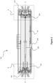
- Figure 2 shows a cross-sectional side view along A-A (as shown in Figure 1 ) of the cleaning accessory 100.
- the rotatable cleaning bar 114 is mounted on a shaft 200 and the shaft 200 is rotatably mounted to the housing 102.
- the rotatable cleaning bar 114 is mounted to the housing 102 such that at least a portion of the rotatable cleaning bar 114 extends through the first air inlet 112.
- the rotatable cleaning bar 114 is arranged to rotate about rotation axis A-A.
- the rotation axis A-A is substantially parallel to a horizontal surface 400 e.g. a floor to be cleaned.
- the shaft 200 is optionally a drive shaft (not shown) which is coupled to the motor 500 for rotating the rotatable cleaning bar 114.
- the drive shaft of the motor 500 is parallel with the rotation axis A-A of the rotatable cleaning bar 114.
- the motor 500 is mounted inside the of rotatable cleaning bar 114. In this case, the drive shaft of the motor 500 is coaxial with the rotation axis A-A of the rotatable cleaning bar 114.
- the rotatable cleaning bar 114 is generally linear in construction and extends along a longitudinal axis A-A.
- the shaft 200 can extend along the rotatable cleaning bar 114 along the axis A-A as shown in Figure 2 .
- the shaft 200 can be formed from two separate sections at a first end 202 and a second end 204 of the rotatable cleaning bar 114.
- the rotatable cleaning bar 114 is a substantially cylindrical element. In other embodiments the rotatable cleaning bar 114 is elongate and substantially cylindrical and comprises ridges and groves. For example, the rotatable cleaning bar 114 can comprise spiral grooves and / or ridges for receiving one or more flexible cleaning elements such as cleaning brushes or ribs.
- the rotatable cleaning bar 114 as shown in Figure 2 comprises at least one flexible cleaning bar element 206.
- the at least one flexible cleaning bar element 206 as shown in Figure 2 is a part of a flexible rubber rib mounted in a spiral on the rotatable cleaning bar 114.
- the flexible cleaning bar element 206 is configured to flex when it engages the surface 400 to be cleaned and pick up dirt and debris.
- the flexible cleaning bar element 206 can be a cleaning brush having a plurality of projecting bristle cleaning elements.
- the rotatable cleaning bar 114 comprises different types of cleaning elements, such as bristles, brushes, silicone ribs, silicone fingers, rubber fins, etc.
- the flexible cleaning elements can be any means suitable for cleaning a surface 400.
- the cleaning accessory 100 comprises at least one rotatable cleaning brush 140.
- a first rotatable cleaning brush 140 comprises a rotatable body 604 (best shown in Figure 6 ) and at least one flexible cleaning element 142 is mounted to the rotatable body 604.
- the at least one flexible cleaning element 142 projects outwards from the first side wall 124 of the housing 102.
- the first rotatable cleaning brush 140 comprises a plurality of flexible cleaning elements 142.
- the flexible cleaning elements 142 are deformable and configured to engage the surface 400 to be cleaned when in a deformed position.
- the flexible cleaning elements 142 are a plurality of discrete groups of bristles as shown in Figures 1 and 2 .
- the first rotatable cleaning brush 140 comprise additionally or alternatively bristles, brushes, silicone ribs, silicone fingers, rubber fins, etc.
- the flexible cleaning elements 142 can optionally be continuous (not shown in the Figures) over the entire first rotatable cleaning brush 140.
- the flexible cleaning elements 142 are deformable between a first mode of operation and a second mode of operation.
- the at least one flexible cleaning element 142 is arranged to rotate in a disengaged position.
- the flexible cleaning elements 142 are arranged to be remote from the surface 400 to be cleaned when rotating in the disengaged position.
- the first rotatable cleaning brush 140 is shown with the flexible cleaning elements 142 in the disengaged position in Figures 3a and 4a.
- Figure 4a shows a cross-sectional side view along A-A of the cleaning accessory 100 in the first mode of operation.
- Figure 3a also shows a perspective view of the cleaning accessory 100 in the first mode of operation.
- first rotatable cleaning brush 140 rotates with the flexible cleaning elements 142 in the disengaged position, the first rotatable cleaning brush 140 does not engage the surface 400 to be cleaned. This means first rotatable cleaning brush 140 does not pick up dirt and spread it around. This is convenient when the cleaning accessory 100 is being used on the surface 400 to be cleaned not near an upright surface 402.
- the at least one flexible cleaning element 142 is arranged to rotate in a cleaning position.
- the flexible cleaning elements 142 are arranged to engage the surface 400 to be cleaned when rotating in the cleaning position.
- the first rotatable cleaning brush 140 is shown with the flexible cleaning elements 142 in the cleaning position in Figures 3b and 4b.
- Figures 4b shows a cross-sectional side view along A-A of the cleaning accessory 100 in the first mode of operation.
- Figure 3b also shows a perspective view of the cleaning accessory 100 in the second mode of operation.
- first rotatable cleaning brush 140 rotates with the flexible cleaning elements 142 in the engaged position, the first rotatable cleaning brush 140 engages the surface 400 to be cleaned. This means first rotatable cleaning brush 140 picks up dirt as discussed further below.
- the cleaning accessory 100 comprises rotating cleaning brushes 140 which are mounted on the outside of the first side wall 124 of the housing 102.
- edge cleaning can be achieved at the same time as cleaning other parts of the floor surface 400.
- a user may have had to perform a series of movements with the cleaning accessory 100 in a direction perpendicular to the upright surface 402 so that the front of the cleaning accessory 100 is adjacent to the edge 404.
- the edge 404 can be cleaned in a single pass of the cleaning accessory 100 in a movement parallel to the upright surface 402 and edge 404.
- the flexible cleaning elements 142 are resiliently deformable. In some examples the flexible cleaning elements 142 are biased into the disengaged position as shown in Figures 3a and 4a . This means that when the flexible cleaning elements 142 are deformed in to the cleaning position and then released, the flexible cleaning elements 142 will return to the disengaged position as shown in Figured 4a. In other words, when the cleaning accessory 100 is moved away from a position engaging the upright surface 402 as shown in Figure 4b , to a position remote from the upright surface 402 as shown in Figure 4a , the flexible cleaning elements 142 return to the disengaged position.
- the flexible cleaning elements 142 extend outwards from the first side wall 124 by a first distance d 1 as shown in Figure 9 .
- the flexible cleaning elements 142 extend outwards from the first side wall by a second distance d 2 .
- the flexible cleaning elements 142 rotate in the disengaged position whereby an end 900 of the flexible cleaning element 142 is maintained at a distance d 3 above the surface 400 to be cleaned.
- the flexible cleaning elements 142 are arranged to flex from the disengaged position to the cleaning position when a force is applied to the at least one flexible cleaning element 142.
- the force to deform the flexible cleaning elements 142 is in a direction parallel to the rotation axis A-A of the rotatable cleaning brush 140.
- the flexible cleaning elements 142 are arranged to deform.
- the flexible cleaning elements 142 extend from the rotation axis A-A to engage the surface 400 to be cleaned in the second mode of operation.
- the flexible cleaning elements 142 and the rotatable cleaning bar 114 extend in a radial direction from the rotation axis A-A towards the surface 400 by the same distance. This means that when the cleaning accessory 100 is moved across the surface 400 to be cleaned, the cleaning accessory 100 remains substantially level.
- the first rotatable cleaning brush 140 is rotatably coupled to the first end 202 of the rotatable cleaning bar 114.
- a second rotatable cleaning brush 210 (as shown in Figure 2 ) is rotatably coupled to the second end 204 of the rotatable cleaning bar 114.
- the second rotatable cleaning brush 210 is identical to the first rotatable cleaning brush 140 as previously described.
- the cleaning accessory 100 has a single rotatable cleaning brush 140 mounted to only one of the first or second end 202, 204 of the rotatable cleaning bar 114.
- edges 404 positioned to either the first side wall 124 or the second side wall 126 can be cleaned with the cleaning accessory 100.
- the first rotatable cleaning brush 140 is rotatably coupled to the rotatable cleaning bar 114 and is fixed to the rotatable cleaning bar 114. In this way, when the rotatable cleaning bar 114 rotates, the first rotatable cleaning brush 140 and the rotatable cleaning bar 114 rotate together.
- the second rotatable cleaning brush 210 is rotatably coupled to the rotatable cleaning bar 114 and is fixed to the rotatable cleaning bar 114. In this way, when the rotatable cleaning bar 114 rotates, the second rotatable cleaning brush 210 and the rotatable cleaning bar 114 rotate together.
- first rotatable cleaning brush 140 and / or the second rotatable cleaning brush 210 are rotatably coupled to the rotatable cleaning bar 114 via a drive mechanism.
- a belt or gears are rotatably coupled between the rotatable cleaning bar 114 and the first rotatable cleaning brush 140 and / or the second rotatable cleaning brush 210.
- Figure 5 shows the second rotatable cleaning brush 210 is rotatably coupled to the rotatable cleaning bar 114 via a drive gear 506.
- the drive gear 506 will be discussed in more detail below in reference to Figure 5 .
- the axis of rotation A-A of the rotatable cleaning bar 114 can be remote from the axis of rotation of the first and / or second rotatable cleaning brush 140, 210.
- the axis of rotation A-A of the rotatable cleaning bar 114 and the axis of rotation of the first and second rotatable cleaning brush 140, 210 are coaxial e.g. rotation axis A-A.
- the first and second rotatable cleaning brushes 140, 210 are optionally removably mountable on the rotatable cleaning bar 114.
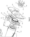
- Figure 5 shows an exploded perspective view of the cleaning accessory 100 at the second end 204 of the rotatable cleaning bar 114.
- Figure 6 shows another exploded perspective view of the cleaning accessory 100 at the first end 202 of the rotatable cleaning bar 114.
- Figures 8a and 8b respectively show close up cross-sectional views of the cleaning accessory 100.
- Figure 8a is represented as dotted box labelled B in Figure 2 .
- Figure 8b is represented as dotted box labelled C in Figure 2 .
- Figure 7 shows a perspective cut away view of the cleaning accessory 100 with the parts shown in Figures 5 and 6 assembled.
- Figure 8a shows the parts shown in Figure 6 in an assembled state.
- the first rotatable cleaning brush 140 projects through a hole 600 in the first side wall 124 of the housing 102.
- the first rotatable cleaning brush 140 slides on to the shaft 200.
- the shaft 200 comprises a flat surface 602 or a keyed surface to prevent relative rotational movement of the first rotatable cleaning brush 140 with respect to the shaft 200 when the first rotatable cleaning brush 140 is mounted to the shaft 200.
- an outer surface 606 of the rotatable body 604 of the first rotatable cleaning brush 140 is flush with or recessed within a first side surface 608 of the first side wall 124 as shown in Figure 1 .
- the rotatable body 604 of the first rotatable cleaning brush 140 comprises a frustoconical shape arranged to be received in a reciprocal recess 808 with a first inclined reciprocal surface 800 in the first side wall 124.
- the frustoconical shape of the rotatable body 604 means that the rotatable body 604 seats correctly in the reciprocal recess 808.
- the rotatable body 604 of the first rotatable cleaning brush 140 does not engage the first inclined reciprocal surface 800 in the first side wall 124. Accordingly the rotatable body 604 is held at a fixed distance from the first inclined reciprocal surface 800 in the first side wall 124.
- the first rotatable cleaning brush 140 is optionally fixed to the shaft 200 of the rotatable cleaning bar 114 with a first screw 802. As shown in Figure 8a , optionally the shaft 200 projects through the first side wall 124 into the reciprocal recess 808. This means that the shaft 200 is visibly presented to the user within the reciprocal recess 808 and the first rotatable cleaning brush 140 is easier to mount on the shaft 200.
- the first rotatable cleaning brush 140 is removeable from the rotatable cleaning bar 114 by removal of the first screw 802.
- the first rotatable cleaning brush 140 in some other examples can be mounted to the rotatable cleaning bar 114 with a toolless connection.
- the first rotatable cleaning brush 140 can be mounted via a bayonet fitting, clips, or any other suitable mechanism.
- the first side wall 124 comprises a bearing housing 804 and a bearing 806 is mounted in the bearing housing 804.
- the shaft 200 is threaded through and engages with the bearing 806 such that the shaft 200, the rotatable cleaning bar 114 and the first rotatable cleaning brush 140 rotate freely with respect to the first side wall 124.
- the first side wall 124 as shown in Figure 6 is mountable to the housing 102 via screws (not shown) or any other suitable fastening device.
- the second rotatable cleaning brush 210 is mountable to the shaft 200 and the rotatable cleaning bar 114 in the same way as discussed with respect to the first rotatable cleaning brush 140.
- the first or the second rotatable cleaning brush 140, 210 is mountable on a drive gear 506 instead of mountable on a shaft 200 or within the rotatable cleaning bar 114 as shown in Figures 8a , 6 .
- the examples as shown in Figures 5 , 8b show the second rotatable cleaning brush 210 mountable on the drive gear 506.
- Figure 8b shows the parts shown in Figure 5 in an assembled state.
- the second rotatable cleaning brush 210 projects through a hole 502 in the second side wall 126 of the housing 102.
- the second rotatable cleaning brush 210 slides on to the drive shaft 504 connected to the drive gear 506.
- the drive shaft 504 comprises a flat surface or a keyed surface to prevent relative rotational movement of the second rotatable cleaning brush 210 with respect to the drive shaft 504 when the second rotatable cleaning brush 210 is mounted to the drive shaft 504.
- the drive shaft 504 is integral with the drive gear 506.
- an outer surface 508 of a rotatable body 510 of the second rotatable cleaning brush 210 is flush with or recessed within a second side surface 512 of the second side wall 126 as shown in Figure 8b .
- the rotatable body 510 of the second rotatable cleaning brush 210 comprises a frustoconical shape arranged to be received in a reciprocal recess 514 with an inclined reciprocal drive surface 810 in the drive gear 506.
- the hole 502 in the second side wall 126 comprises a second inclined reciprocal surface 818 reciprocal to the frustoconical shape of the rotatable body 510 of the second rotatable cleaning brush 210.
- the rotatable body 510 of the second rotatable cleaning brush 210 does not engage the second inclined reciprocal surface 818 in the second side wall 126. Accordingly the rotatable body 510 is held at a fixed distance from the second inclined reciprocal surface 818 in the second side wall 126.
- the rotatable body 510 of the second rotatable cleaning brush 210 engages with the inclined reciprocal drive surface 810 in drive gear 506. This means that the drive gear 506 rotates at the same rate of rotation as the second rotatable cleaning brush 210.
- the second rotatable cleaning brush 210 is optionally fixed to the drive shaft 504 of the drive gear 506 with a second screw 812. In this way, the second rotatable cleaning brush 210 is removeable from the rotatable cleaning bar 114 and the drive gear 506 by removal of the second screw 812.
- the second rotatable cleaning brush 210 in some other examples can be mounted to the drive gear 506 with a toolless connection.
- the second rotatable cleaning brush 210 can be mounted via a bayonet fitting, clips, or any other suitable mechanism.
- the motor 500 is mounted to the housing 102 via a motor mounting plate 520.
- the motor mounting plate 520 comprises fingers 522 for gripping the motor 500 and holding the motor 500 with respect to the housing 102.
- the motor mounting plate 520 is fixed with respect to the housing 102 by e.g. screws (not shown) or any other suitable fastening means.
- the second side wall 126 is optionally fastened to the motor mounting plate 520.
- the motor mounting plate 520 extends in a direction parallel to the second side wall 126 and comprises a bearing housing 814 and a bearing 816 is mounted in the bearing housing 814 (best shown in Figure 8b ).
- the drive shaft 504 is threaded through and engages with the bearing 816 such that the drive shaft 504, the rotatable cleaning bar 114 and the second rotatable cleaning brush 210 rotate freely with respect to the second side wall 126.
- the drive gear 506 is operatively connected to a motor gear 516.
- the motor gear 516 is mounted to a motor shaft (not shown). As shown in Figure 5 , the drive gear 506 and the motor gear 516 are connected via a belt 518. In some other examples the belt 518 is replaced with a gearbox (not shown) for transmitting rotation from the motor shaft to the drive gear 506.
- the rotatable cleaning bar 114 can rotate faster than the first or second rotatable cleaning brush 140, 210.
- the second side wall 126 as shown in Figure 5 is mountable to the housing 102 via screws (not shown) or any other suitable fastening device.
- the first side wall 124 optionally comprises a first side air inlet 300.
- the first side air inlet 300 is not necessary when the cleaning accessory 100 comprises a first or second rotatable cleaning brush 140, 210. This is because the dirt and debris dislodged by the first or second rotatable cleaning brush 140, 210 can be sucked into the air outlet 110 into the first air inlet 112 underneath the cleaning accessory 100. It is preferable to provide a first side air inlet 300 with a first rotating brush 140 because the dirt is more reliably picked up by the cleaning accessory 100.
- the second side wall 126 comprises a second side air inlet 524.
- first side air inlet 300 may only be discussed, but reference to the first side air inlet 300 can refer to alternatively or additionally to the second side air inlet 524.
- the first side air inlet 300 and the second side air inlet 524 respectively provide second airflow paths p 1 , p 2 between the first side air inlet 300 and the second side air inlet 524 and the air outlet 110. Accordingly dirty air flows in from the first side air inlet 300 and / or the second side air inlet 524 to the air outlet 110.
- the second air flow paths p 1 , p 2 in some examples bypass the rotatable cleaning bar 114.
- at least part of the first airflow path and the second airflow paths p 1 , p 2 are located around the rotatable cleaning bar 114.
- the second air flow paths p 1 , p 2 overlap a portion of the first airflow path. This means that the internal structure of the cleaning accessory 100 can be made more compact.
- the cleaning accessory 100 comprises the first rotatable cleaning brush 140.
- the at least one flexible cleaning element 142 is arranged to engage the surface 400 to be cleaned adjacent to the first or second side air inlet 300, 524.
- the at least one flexible cleaning element 142 is arranged to guide dirt towards the first side air inlet 300.
- the first rotatable cleaning brush 140 rotates in a clockwise direction as represented by the curved arrows in Figures 3a and 3b . This means that flexible cleaning elements 142 sweep the surface 400 to be cleaned and guide the dirt towards the first side air inlet 300 as represented by the straight arrow in Figure 3b .
- the dirt and debris becomes entrained in the airflow. The dirt and debris is then sucked into the cleaning accessory 100.
- Figures 3a and 3b show the first rotatable cleaning brush 140 is rotatable as indicated by the arrow in a clockwise direction
- the first cleaning brush 140 is optionally fixed to the first side wall 124. In this way, the first cleaning brush 140 is static and does not rotate with respect to the first side wall 124.
- the second cleaning bush 210 can also be fixed and not rotate with respect to the second side wall 126.
- the first cleaning brush 140 engages the surface 400 to be cleaned adjacent to the first side air inlet 300.
- the first cleaning brush 140 may also guide the dirt and debris on the surface 400 to be cleaned due to the shape and orientation of the flexible cleaning elements 142.
- the flexible cleaning elements 142 of the first cleaning brush 140 are arranged in wedge shape with the apex of the wedge adjacent to the first side air inlet 300. The wedge shaped first cleaning brush 140 then funnels the dirt and debris into the first side air inlet 300 when the cleaning accessory 100 is moved in the forward direction X.
- the first side wall 124 comprises a projecting lip 302 arranged to guide dirt into the first side air inlet 300.
- the projecting lip 302 projects outwardly from the first side wall 124 and extends into the path of dirt swept by the first cleaning brush 140.
- the projecting lip 302 is aligned with the first side air inlet 300. Accordingly, when dirt abuts the projecting lip 302, the dirt will be entrained into the airflow and enter the cleaning accessory 100 at the first side air inlet 300.
- the first side wall 124 also comprises an optional dirt deflector 304. Similar to the projecting lip 302, the dirt deflector 304 projects out from the first side wall 124.
- the dirt deflector 304 is configured to surround at least a part of the perimeter of the first rotatable cleaning brush 140.
- the dirt deflector 304 is arranged to prevent the dirt is not swept backwards or upwards past the cleaning accessory 100. Instead, the dirt deflector 304 comprises a leading edge portion 306 which is directed downwards towards the surface 400 to be cleaned and in the direction X of forward travel.
- the direction T is approximately a tangent to the curve of the leading edge portion 306 of the dirt deflector 304.
- the dirt deflector 304 optionally extends along the perimeter of the first rotatable cleaning brush 140 between 25% to 50% of the length of the perimeter of the first rotatable cleaning brush 140.
- the dirt deflector 304 comprises a projecting finger 308.
- the projecting finger 308 is configured to engage the at least one flexible cleaning element 142 when the at least one flexible cleaning element 142 is rotating in the cleaning position as shown in Figure 3b .
- the projecting finger 308 is configured to engage the at least one flexible cleaning element 142 after the at least one flexible cleaning element 142 has moved past the first side air inlet 300. This means that dirt lodged in the flexible cleaning elements 142 is scraped off when the flexible cleaning elements 142 move past the projecting finger 308. Since the projecting finger 308 causes the flexible cleaning elements 142 to flex during part of the rotation of the first rotatable cleaning brush 140, the dirt can be further encouraged to be flicked off the flexible cleaning elements 142 as the returns to shape.
- the projecting dirt deflector 304 and the projecting lip 302 define a brush recess 406 (best shown in Figures 4a, 4b ).
- the projecting dirt deflector 304 and the projecting lip 302 are arranged to engage the upright surface 402.
- the projecting dirt deflector 304 and the projecting lip 302 are arranged to engage the upright surface 402 and create a partial seal against the upright surface 402.
- the brush recess 406 adjacent to the upright surface 402 encourages the second airflow paths p 1 , p 2 to be positioned around the first rotatable cleaning brush 140. This further reduces the dirt to be flicked out form the brush recess 406 and most of the dirt swept by the first rotatable cleaning brush 140 is entrained in to the air flow.
- the brush recess 406 is closed off from the first air inlet 112 and the dirt collected by the first rotatable cleaning brush 140 is sucked in via the first side air inlet 300.
- the brush recess 406 is configured to receive the at least one flexible cleaning element 142 when the first side wall 124 is adjacent to the upright surface 402 and the at least one flexible cleaning element 142 flexes into the cleaning position. Accordingly, the brush recess 406 is configured to receive the first rotatable cleaning brush 140 and the flexible cleaning elements 142 when the first rotatable cleaning brush 140 is in the second mode of operation e.g., the cleaning position.
- the brush recess 406 allows the first rotatable cleaning brush 140 to freely rotate without interference from the housing 102 and clean the upright surface 402 and the edge 404.
- the biasing force of the flexible cleaning elements 142 means that the flexible cleaning elements 142 will be urged against the upright surface 402 and the edge 404. This means that a lower part of the upright surface 402 will also be cleaned by the first rotatable cleaning brush 140 during operation.
Landscapes
- Engineering & Computer Science (AREA)
- Mechanical Engineering (AREA)
- Nozzles For Electric Vacuum Cleaners (AREA)
Description
- The present invention relates to a vacuum cleaner and a floor cleaning head accessory for a vacuum cleaner. In particular the present invention relates to a cleaning accessory with improved edge cleaning.
- Vacuum cleaners such as stickvacs, upright vacuum cleaners or floor vacuum cleaners with a hose attachment typically comprise cleaning accessories for cleaning floors and the like. The invention comprises a floor cleaning head and the floor cleaning head comprises a rotating brushes to improve dirt pick up.
- When a user cleans a floor surface near an upright surface such as a wall, the user may find that the width of the floor cleaning head prevents dirt pick up at the edge of the floor surface and the wall. This means that the user has to repeat the cleaning process with another accessory such as a crevice tool to ensure the edge of the floor surface is properly cleaned.
- Some known cleaning devices such as robotic vacuum cleaners e.g. as shown in
US 8,239,992 ,WO 2019/035050 A1 orDE 10 2015 101587 have additional brushes for cleaning surfaces at the side of the cleaning device. A problem with this arrangement is that brushes do not adequately engage the edge of the floor surface and the wall and the robotic vacuum cleaner does not have a powerful motor fan assembly. This means that dirt pick up along the sides of the robotic vacuum cleaner may not be sufficient to pick up dirt with a single pass. - Examples of the present invention aim to address the aforementioned problems.
- The invention is defined through the features of independent claim 1. Further features are defined in the appended claims.
- Optionally, the at least one flexible cleaning element is biased to the disengaged position.
- Optionally, the at least one flexible cleaning element is arranged to flex from the disengaged position to the cleaning position when a force is applied to the at least one flexible cleaning element in a direction parallel to the rotation axis of the rotatable cleaning brush.
- Optionally, the at least one flexible cleaning element is arranged to flex from the disengaged position to the cleaning position when the side of the housing is adjacent to an upright surface.
- Optionally, the cleaning accessory comprises a rotatable cleaning bar rotatably mounted within the housing and the at least one rotatable cleaning brush is rotatably coupled to the rotatable cleaning bar.
- Optionally, the rotatable cleaning bar comprises a first end arranged at the side of the housing and a first rotatable cleaning brush is mounted to the first end.
- Optionally, the at least one rotatable cleaning brush comprises a rotatable body and at least part of the rotatable body is arranged to project through the side of the housing to mount to the first end of the rotatable cleaning bar.
- Optionally, the at least one rotatable cleaning brush is removably mountable on the rotatable cleaning bar.
- Optionally, a drive mechanism is rotatably coupled between the at least one rotatable cleaning brush and the rotatable cleaning bar.
- Optionally, the drive mechanism comprises a drive gear fixable to the at least one rotatable cleaning brush and the rotatable cleaning bar.
- Optionally, the drive mechanism is configured to rotate the at least one rotatable cleaning brush and the rotatable cleaning bar at the same rate of rotation.
- Optionally, the drive mechanism comprises a motor.
- Optionally, the motor is mounted within the rotatable cleaning bar.
- Optionally, the motor is mounted to the housing adjacent to the rotatable cleaning bar.
- Optionally, the at least one rotatable cleaning brush and the rotatable cleaning bar are arranged to rotate about a common rotation axis.
- Optionally, the at least one flexible element when rotating in the cleaning position and the rotatable cleaning bar extend radially from the common rotation axis the same distance.
- Optionally, the at least one flexible element does not project below a lower wall of the housing adjacent to the surface to be cleaned when rotating in the disengaged position.
- Optionally, the wherein the rotatable cleaning bar comprises a second end and a second rotatable cleaning brush is mounted to the second end.
- Various other aspects and further examples are also described in the following detailed description and in the attached claims with reference to the accompanying drawings, in which:
-
Figure 1 shows a perspective view of a cleaning accessory for a vacuum cleaner according to an example; -
Figure 2 shows a cross-sectional side view along A-A of a cleaning accessory for a vacuum cleaner according to an example; -
Figures 3a and 3b show a perspective view of a cleaning accessory for a vacuum cleaner respectively in different modes of operation according to an example; -
Figures 4a and 4b show a cross-sectional side view along A-A of a cleaning accessory for a vacuum cleaner respectively in different modes of operation according to an example; -
Figure 5 shows an exploded perspective view of a cleaning accessory for a vacuum cleaner according to an example; -
Figure 6 shows another exploded perspective view of a cleaning accessory for a vacuum cleaner according to an example; -
Figure 7 shows a perspective cut away view of a cleaning accessory for a vacuum cleaner according to an example; -
Figures 8a and 8b show close up cross-sectional views of a cleaning accessory for a vacuum cleaner according to an example; and -
Figure 9 shows a cross-sectional underneath plan view along A-A of a cleaning accessory for a vacuum cleaner according to an example. -
Figure 1 shows a perspective view of acleaning accessory 100 for a vacuum cleaner (not shown). Thecleaning accessory 100 is optionally a floor cleaning head arranged to engage and clean afloor surface 400 to be cleaned. Thecleaning accessory 100 comprises ahousing 102 on which an optional articulatedjoint 104 is mounted. The articulatedjoint 104 couples thehousing 102 to aneck portion 106. Thehousing 102 is arranged to move over asurface 400 to be cleaned such as a floor. In some examples, alower surface 120 of thehousing 102 optionally comprises one or more wheels (not shown) for engaging thesurface 400 to be cleaned. - The
housing 102 comprises afirst side wall 124 and asecond side wall 126, afront wall 122 and aback wall 128. Thehousing 102 further comprises atop wall 130 and alower wall 120. In this way thehousing 102 defines an enclosure for mounting one or more components of thecleaning accessory 100. Thefront wall 122 faces the direction of travel when a user pushes thecleaning accessory 100 on asurface 400 to be cleaned away from themselves. The forwards direction of travel of thecleaning accessory 100 is illustrated inFigure 1 by the arrow labelled X. Likewise, theback wall 128 faces the direction of travel when a user pulls the cleaning accessory on asurface 400 to be cleaned away towards themselves. - The
neck portion 106 comprises anattachment mechanism 108 for attaching to a hose (not shown), extension tube (not shown), or the housing (not shown) of the vacuum cleaner. Theattachment mechanism 108 is known and will not be described in any further detail. - The
cleaning accessory 100 is connectable to a handheld vacuum cleaner via an extension tube, a canister vacuum cleaner via a hose or directly to an upright or a stickvac vacuum cleaner. Theneck portion 106 comprises anair outlet 110 which is in fluid communication with afirst air inlet 112 in thehousing 102. Theair outlet 110 is in fluid communication with a motor-fan assembly (not shown) in the vacuum cleaner. In this way, a first airflow path is provided between thefirst air inlet 112 and theair outlet 110. Accordingly dirty air flows in from thefirst air inlet 112 to theair outlet 110. In some examples, thefirst air inlet 112 extends across the width of thehousing 102. As shown inFigure 9 , thefirst air inlet 112 is positioned on an underside of thehousing 102 e.g. on thelower surface 120 of thehousing 102.Figure 9 shows a cross-sectional underneath plan view along A-A of thecleaning accessory 100. This means that thefirst air inlet 112 is adjacent to thesurface 400 to be cleaned during operation. In some examples thefirst air inlet 112 extends to thefront wall 122 of thehousing 102. - The
neck portion 106 may optionally comprise electrical power and control wires for powering and controlling functionality in the cleaningaccessory 100. The vacuum cleaner can optionally comprise one or more control buttons (not shown) for actuating a motor 500 (best shown inFigure 5 ) to drive arotatable cleaning bar 114. Therotatable cleaning bar 114 may also be known as a brush bar and will be described in more detail below. - In some examples, the
motor 500 is mounted in amotor housing portion 118 of thehousing 102. Themotor 500 will be described in more detail below in reference toFigure 5 . In some other examples which are not shown in the Figures, themotor 500 is mounted within therotatable cleaning bar 114. - The articulated joint 104 provides at least two degrees of freedom of the
housing 102 with respect to theneck portion 106. The articulated joint 104 as shown inFigure 1 comprises two pivot axes which are mounted perpendicular to each other. The articulated joint 104 is known and will not be discussed in any further detail. - The cleaning
accessory 100 optionally comprisesrotatable cleaning bar 114 which is rotatably mounted in the cleaningaccessory 100. Whilst the Figures show arotatable cleaning bar 114, in some alternative examples, there is norotatable cleaning bar 114. In this case, the dirt pick up into thefirst air inlet 112 is only due to the airflow. Hereinafter, all the examples will be discussed in reference to the Figures which show arotatable cleaning bar 114 rotatably mounted to thehousing 102. - In some embodiments, the
rotatable cleaning bar 114 is optionally removably mountable in thehousing 102. Removal of therotatable cleaning bar 114 is known and will not be discussed in further detail. Therotatable cleaning bar 114 is optionally mounted beneath atransparent cover 116 which is partially shown inFigure 1 for the purposes of clarity. This means that the user can see when therotatable cleaning bar 114 is in operation and when therotatable cleaning bar 114 requires maintenance. - Turning to
Figure 2 , therotatable cleaning bar 114 will be described in further detail.Figure 2 shows a cross-sectional side view along A-A (as shown inFigure 1 ) of the cleaningaccessory 100. Therotatable cleaning bar 114 is mounted on ashaft 200 and theshaft 200 is rotatably mounted to thehousing 102. Therotatable cleaning bar 114 is mounted to thehousing 102 such that at least a portion of therotatable cleaning bar 114 extends through thefirst air inlet 112. Therotatable cleaning bar 114 is arranged to rotate about rotation axis A-A. The rotation axis A-A is substantially parallel to ahorizontal surface 400 e.g. a floor to be cleaned. - In some embodiments, the
shaft 200 is optionally a drive shaft (not shown) which is coupled to themotor 500 for rotating therotatable cleaning bar 114. The drive shaft of themotor 500 is parallel with the rotation axis A-A of therotatable cleaning bar 114. Alternatively, themotor 500 is mounted inside the ofrotatable cleaning bar 114. In this case, the drive shaft of themotor 500 is coaxial with the rotation axis A-A of therotatable cleaning bar 114. - The
rotatable cleaning bar 114 is generally linear in construction and extends along a longitudinal axis A-A. Theshaft 200 can extend along therotatable cleaning bar 114 along the axis A-A as shown inFigure 2 . Alternatively, theshaft 200 can be formed from two separate sections at afirst end 202 and asecond end 204 of therotatable cleaning bar 114. - In some embodiments the
rotatable cleaning bar 114 is a substantially cylindrical element. In other embodiments therotatable cleaning bar 114 is elongate and substantially cylindrical and comprises ridges and groves. For example, therotatable cleaning bar 114 can comprise spiral grooves and / or ridges for receiving one or more flexible cleaning elements such as cleaning brushes or ribs. - In some examples, the
rotatable cleaning bar 114 as shown inFigure 2 comprises at least one flexiblecleaning bar element 206. The at least one flexiblecleaning bar element 206 as shown inFigure 2 is a part of a flexible rubber rib mounted in a spiral on therotatable cleaning bar 114. The flexiblecleaning bar element 206 is configured to flex when it engages thesurface 400 to be cleaned and pick up dirt and debris. In other examples the flexiblecleaning bar element 206 can be a cleaning brush having a plurality of projecting bristle cleaning elements. Additionally, or alternatively therotatable cleaning bar 114 comprises different types of cleaning elements, such as bristles, brushes, silicone ribs, silicone fingers, rubber fins, etc. In some embodiments, the flexible cleaning elements can be any means suitable for cleaning asurface 400. - Further discussion of the cleaning
accessory 100 will be made in reference toFigures 4a and 4b . When a user cleans afloor surface 400 near anupright surface 402 such as a wall, the user may find that the width of a cleaningaccessory 100 prevents dirt pick up at theedge 404 of thefloor surface 400 and theupright surface 402. This means that the user has to repeat the cleaning process with another accessory such as a crevice tool or repeatedly pass the cleaningaccessory 100 over theedge 404 to ensure theedge 404 of thefloor surface 400 is properly cleaned. In order to improve the edge cleaning of the floor, the cleaningaccessory 100 comprises at least onerotatable cleaning brush 140. - As shown in
Figure 1 , a firstrotatable cleaning brush 140 comprises a rotatable body 604 (best shown inFigure 6 ) and at least oneflexible cleaning element 142 is mounted to therotatable body 604. The at least oneflexible cleaning element 142 projects outwards from thefirst side wall 124 of thehousing 102. In some examples the firstrotatable cleaning brush 140 comprises a plurality offlexible cleaning elements 142. Theflexible cleaning elements 142 are deformable and configured to engage thesurface 400 to be cleaned when in a deformed position. - In some examples, the
flexible cleaning elements 142 are a plurality of discrete groups of bristles as shown inFigures 1 and2 . In some other examples, the firstrotatable cleaning brush 140 comprise additionally or alternatively bristles, brushes, silicone ribs, silicone fingers, rubber fins, etc. Theflexible cleaning elements 142 can optionally be continuous (not shown in the Figures) over the entire firstrotatable cleaning brush 140. - In the invention the
flexible cleaning elements 142 are deformable between a first mode of operation and a second mode of operation. - In the first mode of operation the at least one
flexible cleaning element 142 is arranged to rotate in a disengaged position. In the disengaged position, theflexible cleaning elements 142 are arranged to be remote from thesurface 400 to be cleaned when rotating in the disengaged position. The firstrotatable cleaning brush 140 is shown with theflexible cleaning elements 142 in the disengaged position inFigures 3a and4a. Figure 4a shows a cross-sectional side view along A-A of the cleaningaccessory 100 in the first mode of operation.Figure 3a also shows a perspective view of the cleaningaccessory 100 in the first mode of operation. - This means that when the first
rotatable cleaning brush 140 rotates with theflexible cleaning elements 142 in the disengaged position, the firstrotatable cleaning brush 140 does not engage thesurface 400 to be cleaned. This means firstrotatable cleaning brush 140 does not pick up dirt and spread it around. This is convenient when the cleaningaccessory 100 is being used on thesurface 400 to be cleaned not near anupright surface 402. - In the second mode of operation, the at least one
flexible cleaning element 142 is arranged to rotate in a cleaning position. In the cleaning position, theflexible cleaning elements 142 are arranged to engage thesurface 400 to be cleaned when rotating in the cleaning position. The firstrotatable cleaning brush 140 is shown with theflexible cleaning elements 142 in the cleaning position inFigures 3b and4b. Figures 4b shows a cross-sectional side view along A-A of the cleaningaccessory 100 in the first mode of operation.Figure 3b also shows a perspective view of the cleaningaccessory 100 in the second mode of operation. - This means that when the first
rotatable cleaning brush 140 rotates with theflexible cleaning elements 142 in the engaged position, the firstrotatable cleaning brush 140 engages thesurface 400 to be cleaned. This means firstrotatable cleaning brush 140 picks up dirt as discussed further below. - Accordingly, the cleaning
accessory 100 comprises rotating cleaning brushes 140 which are mounted on the outside of thefirst side wall 124 of thehousing 102. This means that edge cleaning of thesurface 400 to be cleaned near anupright surface 402 e.g. a wall, kickboard, skirting board, or otherupright surface 402 intersecting with thesurface 400 to be cleaned can be achieved when moving the cleaningaccessory 100 in a direction parallel to theupright surface 402. - This means that up to the edge cleaning can be achieved at the same time as cleaning other parts of the
floor surface 400. Previously, a user may have had to perform a series of movements with the cleaningaccessory 100 in a direction perpendicular to theupright surface 402 so that the front of the cleaningaccessory 100 is adjacent to theedge 404. However, in contrast theedge 404 can be cleaned in a single pass of the cleaningaccessory 100 in a movement parallel to theupright surface 402 andedge 404. - The
flexible cleaning elements 142 are resiliently deformable. In some examples theflexible cleaning elements 142 are biased into the disengaged position as shown inFigures 3a and4a . This means that when theflexible cleaning elements 142 are deformed in to the cleaning position and then released, theflexible cleaning elements 142 will return to the disengaged position as shown in Figured 4a. In other words, when the cleaningaccessory 100 is moved away from a position engaging theupright surface 402 as shown inFigure 4b , to a position remote from theupright surface 402 as shown inFigure 4a , theflexible cleaning elements 142 return to the disengaged position. - In the first mode of operation, the
flexible cleaning elements 142 extend outwards from thefirst side wall 124 by a first distance d1 as shown inFigure 9 . In the second mode of operation, theflexible cleaning elements 142 extend outwards from the first side wall by a second distance d2. In the second mode of operation, theflexible cleaning elements 142 rotate in the disengaged position whereby anend 900 of theflexible cleaning element 142 is maintained at a distance d3 above thesurface 400 to be cleaned. - The
flexible cleaning elements 142 are arranged to flex from the disengaged position to the cleaning position when a force is applied to the at least oneflexible cleaning element 142. In some examples, the force to deform theflexible cleaning elements 142 is in a direction parallel to the rotation axis A-A of therotatable cleaning brush 140. For example, when the cleaningaccessory 100 is moved adjacent (represented by the arrow inFigure 4b ) to anupright surface 402 such as a wall, theflexible cleaning elements 142 are arranged to deform. - As mentioned above, in some examples the
flexible cleaning elements 142 extend from the rotation axis A-A to engage thesurface 400 to be cleaned in the second mode of operation. When theflexible cleaning elements 142 are in the second mode of operation, theflexible cleaning elements 142 and therotatable cleaning bar 114 extend in a radial direction from the rotation axis A-A towards thesurface 400 by the same distance. This means that when the cleaningaccessory 100 is moved across thesurface 400 to be cleaned, the cleaningaccessory 100 remains substantially level. - In some examples, the first
rotatable cleaning brush 140 is rotatably coupled to thefirst end 202 of therotatable cleaning bar 114. In some further examples additionally or alternatively a second rotatable cleaning brush 210 (as shown inFigure 2 ) is rotatably coupled to thesecond end 204 of therotatable cleaning bar 114. The secondrotatable cleaning brush 210 is identical to the firstrotatable cleaning brush 140 as previously described. - In some examples optionally the cleaning
accessory 100 has a singlerotatable cleaning brush 140 mounted to only one of the first orsecond end rotatable cleaning bar 114. In some other examples as shown inFigure 2 , there are a first and second rotatable cleaning brushes 140, 210 mounted to therotatable cleaning bar 114. By having first and second rotatable cleaning brushes 140, 210,edges 404 positioned to either thefirst side wall 124 or thesecond side wall 126 can be cleaned with the cleaningaccessory 100. In some other examples there are optionally more than two rotatable cleaning brushes and there can be any suitable number of rotatable cleaning brushes projecting out of the sides of the cleaningaccessory 100. - In some examples, the first
rotatable cleaning brush 140 is rotatably coupled to therotatable cleaning bar 114 and is fixed to therotatable cleaning bar 114. In this way, when therotatable cleaning bar 114 rotates, the firstrotatable cleaning brush 140 and therotatable cleaning bar 114 rotate together. Similarly, in some examples, the secondrotatable cleaning brush 210 is rotatably coupled to therotatable cleaning bar 114 and is fixed to therotatable cleaning bar 114. In this way, when therotatable cleaning bar 114 rotates, the secondrotatable cleaning brush 210 and therotatable cleaning bar 114 rotate together. - In some other examples, the first
rotatable cleaning brush 140 and / or the secondrotatable cleaning brush 210 are rotatably coupled to therotatable cleaning bar 114 via a drive mechanism. For example, a belt or gears are rotatably coupled between therotatable cleaning bar 114 and the firstrotatable cleaning brush 140 and / or the secondrotatable cleaning brush 210.Figure 5 shows the secondrotatable cleaning brush 210 is rotatably coupled to therotatable cleaning bar 114 via adrive gear 506. Thedrive gear 506 will be discussed in more detail below in reference toFigure 5 . - This means that the axis of rotation A-A of the
rotatable cleaning bar 114 can be remote from the axis of rotation of the first and / or secondrotatable cleaning brush rotatable cleaning bar 114 and the axis of rotation of the first and secondrotatable cleaning brush - In some examples, the first and second rotatable cleaning brushes 140, 210 are optionally removably mountable on the
rotatable cleaning bar 114. Turning toFigures 5 ,6 ,7 ,8a and 8b , the construction of the cleaningaccessory 100 will be discussed in further detail.Figure 5 shows an exploded perspective view of the cleaningaccessory 100 at thesecond end 204 of therotatable cleaning bar 114.Figure 6 shows another exploded perspective view of the cleaningaccessory 100 at thefirst end 202 of therotatable cleaning bar 114.Figures 8a and 8b respectively show close up cross-sectional views of the cleaningaccessory 100.Figure 8a is represented as dotted box labelled B inFigure 2 .Figure 8b is represented as dotted box labelled C inFigure 2 .Figure 7 shows a perspective cut away view of the cleaningaccessory 100 with the parts shown inFigures 5 and6 assembled. - Turning to
Figure 6 , the firstrotatable cleaning brush 140 will be discussed in further detail.Figure 8a shows the parts shown inFigure 6 in an assembled state. The firstrotatable cleaning brush 140 projects through ahole 600 in thefirst side wall 124 of thehousing 102. The firstrotatable cleaning brush 140 slides on to theshaft 200. In some examples, theshaft 200 comprises aflat surface 602 or a keyed surface to prevent relative rotational movement of the firstrotatable cleaning brush 140 with respect to theshaft 200 when the firstrotatable cleaning brush 140 is mounted to theshaft 200. When the firstrotatable cleaning brush 140 is mounted on theshaft 200, anouter surface 606 of therotatable body 604 of the firstrotatable cleaning brush 140 is flush with or recessed within afirst side surface 608 of thefirst side wall 124 as shown inFigure 1 . - In some examples, the
rotatable body 604 of the firstrotatable cleaning brush 140 comprises a frustoconical shape arranged to be received in areciprocal recess 808 with a first inclinedreciprocal surface 800 in thefirst side wall 124. Advantageously, the frustoconical shape of therotatable body 604 means that therotatable body 604 seats correctly in thereciprocal recess 808. - In some examples the
rotatable body 604 of the firstrotatable cleaning brush 140 does not engage the first inclinedreciprocal surface 800 in thefirst side wall 124. Accordingly therotatable body 604 is held at a fixed distance from the first inclinedreciprocal surface 800 in thefirst side wall 124. The firstrotatable cleaning brush 140 is optionally fixed to theshaft 200 of therotatable cleaning bar 114 with afirst screw 802. As shown inFigure 8a , optionally theshaft 200 projects through thefirst side wall 124 into thereciprocal recess 808. This means that theshaft 200 is visibly presented to the user within thereciprocal recess 808 and the firstrotatable cleaning brush 140 is easier to mount on theshaft 200. - In this way, the first
rotatable cleaning brush 140 is removeable from therotatable cleaning bar 114 by removal of thefirst screw 802. The firstrotatable cleaning brush 140 in some other examples can be mounted to therotatable cleaning bar 114 with a toolless connection. For example, the firstrotatable cleaning brush 140 can be mounted via a bayonet fitting, clips, or any other suitable mechanism. - The
first side wall 124 comprises a bearinghousing 804 and abearing 806 is mounted in the bearinghousing 804. Theshaft 200 is threaded through and engages with the bearing 806 such that theshaft 200, therotatable cleaning bar 114 and the firstrotatable cleaning brush 140 rotate freely with respect to thefirst side wall 124. - The
first side wall 124 as shown inFigure 6 is mountable to thehousing 102 via screws (not shown) or any other suitable fastening device. - Optionally in some examples, the second
rotatable cleaning brush 210 is mountable to theshaft 200 and therotatable cleaning bar 114 in the same way as discussed with respect to the firstrotatable cleaning brush 140. - However, in some alternative examples, the first or the second
rotatable cleaning brush drive gear 506 instead of mountable on ashaft 200 or within therotatable cleaning bar 114 as shown inFigures 8a ,6 . The examples as shown inFigures 5 ,8b show the secondrotatable cleaning brush 210 mountable on thedrive gear 506. - Turning to
Figure 5 , the secondrotatable cleaning brush 210 will be discussed in further detail.Figure 8b shows the parts shown inFigure 5 in an assembled state. - The second
rotatable cleaning brush 210 projects through ahole 502 in thesecond side wall 126 of thehousing 102. The secondrotatable cleaning brush 210 slides on to thedrive shaft 504 connected to thedrive gear 506. In some examples, thedrive shaft 504 comprises a flat surface or a keyed surface to prevent relative rotational movement of the secondrotatable cleaning brush 210 with respect to thedrive shaft 504 when the secondrotatable cleaning brush 210 is mounted to thedrive shaft 504. As shown inFigure 8b , thedrive shaft 504 is integral with thedrive gear 506. When the secondrotatable cleaning brush 210 is mounted on thedrive shaft 504, anouter surface 508 of arotatable body 510 of the secondrotatable cleaning brush 210 is flush with or recessed within asecond side surface 512 of thesecond side wall 126 as shown inFigure 8b . - In some examples, the
rotatable body 510 of the secondrotatable cleaning brush 210 comprises a frustoconical shape arranged to be received in areciprocal recess 514 with an inclinedreciprocal drive surface 810 in thedrive gear 506. In addition, optionally, thehole 502 in thesecond side wall 126 comprises a second inclinedreciprocal surface 818 reciprocal to the frustoconical shape of therotatable body 510 of the secondrotatable cleaning brush 210. - In some examples the
rotatable body 510 of the secondrotatable cleaning brush 210 does not engage the second inclinedreciprocal surface 818 in thesecond side wall 126. Accordingly therotatable body 510 is held at a fixed distance from the second inclinedreciprocal surface 818 in thesecond side wall 126. - In some examples the
rotatable body 510 of the secondrotatable cleaning brush 210 engages with the inclinedreciprocal drive surface 810 indrive gear 506. This means that thedrive gear 506 rotates at the same rate of rotation as the secondrotatable cleaning brush 210. - The second
rotatable cleaning brush 210 is optionally fixed to thedrive shaft 504 of thedrive gear 506 with asecond screw 812. In this way, the secondrotatable cleaning brush 210 is removeable from therotatable cleaning bar 114 and thedrive gear 506 by removal of thesecond screw 812. The secondrotatable cleaning brush 210 in some other examples can be mounted to thedrive gear 506 with a toolless connection. For example, the secondrotatable cleaning brush 210 can be mounted via a bayonet fitting, clips, or any other suitable mechanism. - As shown in
Figure 5 , themotor 500 is mounted to thehousing 102 via amotor mounting plate 520. Themotor mounting plate 520 comprisesfingers 522 for gripping themotor 500 and holding themotor 500 with respect to thehousing 102. Themotor mounting plate 520 is fixed with respect to thehousing 102 by e.g. screws (not shown) or any other suitable fastening means. In some examples, thesecond side wall 126 is optionally fastened to themotor mounting plate 520. Themotor mounting plate 520 extends in a direction parallel to thesecond side wall 126 and comprises a bearinghousing 814 and abearing 816 is mounted in the bearing housing 814 (best shown inFigure 8b ). Thedrive shaft 504 is threaded through and engages with the bearing 816 such that thedrive shaft 504, therotatable cleaning bar 114 and the secondrotatable cleaning brush 210 rotate freely with respect to thesecond side wall 126. - The
drive gear 506 is operatively connected to amotor gear 516. Themotor gear 516 is mounted to a motor shaft (not shown). As shown inFigure 5 , thedrive gear 506 and themotor gear 516 are connected via abelt 518. In some other examples thebelt 518 is replaced with a gearbox (not shown) for transmitting rotation from the motor shaft to thedrive gear 506. - In some further examples, there is optionally one or more gears operatively connected between the
rotatable cleaning bar 114 and the first or secondrotatable cleaning brush rotatable cleaning bar 114 and the first or secondrotatable cleaning brush rotatable cleaning bar 114 can rotate faster than the first or secondrotatable cleaning brush - The
second side wall 126 as shown inFigure 5 is mountable to thehousing 102 via screws (not shown) or any other suitable fastening device. - Another feature of the cleaning
accessory 100 will now be discussed in reference toFigures 3a, 3b ,4a, 4b and9 . - In some examples the
first side wall 124 optionally comprises a firstside air inlet 300. The firstside air inlet 300 is not necessary when the cleaningaccessory 100 comprises a first or secondrotatable cleaning brush rotatable cleaning brush air outlet 110 into thefirst air inlet 112 underneath the cleaningaccessory 100. It is preferable to provide a firstside air inlet 300 with a firstrotating brush 140 because the dirt is more reliably picked up by the cleaningaccessory 100. - In some other examples additionally or alternatively the
second side wall 126 comprises a secondside air inlet 524. In the examples below the firstside air inlet 300 may only be discussed, but reference to the firstside air inlet 300 can refer to alternatively or additionally to the secondside air inlet 524. - As shown in
Figure 9 , the firstside air inlet 300 and the secondside air inlet 524 respectively provide second airflow paths p1, p2 between the firstside air inlet 300 and the secondside air inlet 524 and theair outlet 110. Accordingly dirty air flows in from the firstside air inlet 300 and / or the secondside air inlet 524 to theair outlet 110. The second air flow paths p1, p2 in some examples bypass therotatable cleaning bar 114. In some other examples, at least part of the first airflow path and the second airflow paths p1, p2 are located around therotatable cleaning bar 114. In some examples, the second air flow paths p1, p2 overlap a portion of the first airflow path. This means that the internal structure of the cleaningaccessory 100 can be made more compact. - As mentioned above, the cleaning
accessory 100 comprises the firstrotatable cleaning brush 140. In some examples, the at least oneflexible cleaning element 142 is arranged to engage thesurface 400 to be cleaned adjacent to the first or secondside air inlet flexible cleaning element 142 is arranged to guide dirt towards the firstside air inlet 300. As shown inFigure 3 , the firstrotatable cleaning brush 140 rotates in a clockwise direction as represented by the curved arrows inFigures 3a and 3b . This means thatflexible cleaning elements 142 sweep thesurface 400 to be cleaned and guide the dirt towards the firstside air inlet 300 as represented by the straight arrow inFigure 3b . As the dirt and debris is moved towards the firstside air inlet 300 by theflexible cleaning elements 142, the dirt and debris becomes entrained in the airflow. The dirt and debris is then sucked into the cleaningaccessory 100. - Whilst
Figures 3a and 3b show the firstrotatable cleaning brush 140 is rotatable as indicated by the arrow in a clockwise direction, in other alternative examples, thefirst cleaning brush 140 is optionally fixed to thefirst side wall 124. In this way, thefirst cleaning brush 140 is static and does not rotate with respect to thefirst side wall 124. Additionally or alternatively, thesecond cleaning bush 210 can also be fixed and not rotate with respect to thesecond side wall 126. - In the example where the first
rotatable cleaning brush 140 is fixed with respect to thehousing 102, thefirst cleaning brush 140 engages thesurface 400 to be cleaned adjacent to the firstside air inlet 300. Thefirst cleaning brush 140 may also guide the dirt and debris on thesurface 400 to be cleaned due to the shape and orientation of theflexible cleaning elements 142. For example, theflexible cleaning elements 142 of thefirst cleaning brush 140 are arranged in wedge shape with the apex of the wedge adjacent to the firstside air inlet 300. The wedge shaped first cleaningbrush 140 then funnels the dirt and debris into the firstside air inlet 300 when the cleaningaccessory 100 is moved in the forward direction X. - As shown in
Figures 3a and 3b , thefirst side wall 124 comprises a projectinglip 302 arranged to guide dirt into the firstside air inlet 300. The projectinglip 302 projects outwardly from thefirst side wall 124 and extends into the path of dirt swept by thefirst cleaning brush 140. In some examples, the projectinglip 302 is aligned with the firstside air inlet 300. Accordingly, when dirt abuts the projectinglip 302, the dirt will be entrained into the airflow and enter the cleaningaccessory 100 at the firstside air inlet 300. - The
first side wall 124 also comprises anoptional dirt deflector 304. Similar to the projectinglip 302, thedirt deflector 304 projects out from thefirst side wall 124. Thedirt deflector 304 is configured to surround at least a part of the perimeter of the firstrotatable cleaning brush 140. Thedirt deflector 304 is arranged to prevent the dirt is not swept backwards or upwards past the cleaningaccessory 100. Instead, thedirt deflector 304 comprises aleading edge portion 306 which is directed downwards towards thesurface 400 to be cleaned and in the direction X of forward travel. This means that if any dirt or debris is swept past the firstside air inlet 300 by the rotating firstrotatable cleaning brush 140, the dirt and debris will be flicked from the firstrotatable cleaning brush 140 and releases in a direction T. The direction T is approximately a tangent to the curve of theleading edge portion 306 of thedirt deflector 304. - In some examples, the
dirt deflector 304 optionally extends along the perimeter of the firstrotatable cleaning brush 140 between 25% to 50% of the length of the perimeter of the firstrotatable cleaning brush 140. - In some examples, optionally the
dirt deflector 304 comprises a projectingfinger 308. The projectingfinger 308 is configured to engage the at least oneflexible cleaning element 142 when the at least oneflexible cleaning element 142 is rotating in the cleaning position as shown inFigure 3b . The projectingfinger 308 is configured to engage the at least oneflexible cleaning element 142 after the at least oneflexible cleaning element 142 has moved past the firstside air inlet 300. This means that dirt lodged in theflexible cleaning elements 142 is scraped off when theflexible cleaning elements 142 move past the projectingfinger 308. Since the projectingfinger 308 causes theflexible cleaning elements 142 to flex during part of the rotation of the firstrotatable cleaning brush 140, the dirt can be further encouraged to be flicked off theflexible cleaning elements 142 as the returns to shape. - The projecting
dirt deflector 304 and the projectinglip 302 define a brush recess 406 (best shown inFigures 4a, 4b ). The projectingdirt deflector 304 and the projectinglip 302 are arranged to engage theupright surface 402. In some examples, the projectingdirt deflector 304 and the projectinglip 302 are arranged to engage theupright surface 402 and create a partial seal against theupright surface 402. - This means that the
brush recess 406 adjacent to theupright surface 402 encourages the second airflow paths p1, p2 to be positioned around the firstrotatable cleaning brush 140. This further reduces the dirt to be flicked out form thebrush recess 406 and most of the dirt swept by the firstrotatable cleaning brush 140 is entrained in to the air flow. - When the cleaning
accessory 100 is pushed against theupright surface 402, thebrush recess 406 is closed off from thefirst air inlet 112 and the dirt collected by the firstrotatable cleaning brush 140 is sucked in via the firstside air inlet 300. - The
brush recess 406 is configured to receive the at least oneflexible cleaning element 142 when thefirst side wall 124 is adjacent to theupright surface 402 and the at least oneflexible cleaning element 142 flexes into the cleaning position. Accordingly, thebrush recess 406 is configured to receive the firstrotatable cleaning brush 140 and theflexible cleaning elements 142 when the firstrotatable cleaning brush 140 is in the second mode of operation e.g., the cleaning position. - As can be seen from
Figure 4b , thebrush recess 406 allows the firstrotatable cleaning brush 140 to freely rotate without interference from thehousing 102 and clean theupright surface 402 and theedge 404. In some examples, the biasing force of theflexible cleaning elements 142 means that theflexible cleaning elements 142 will be urged against theupright surface 402 and theedge 404. This means that a lower part of theupright surface 402 will also be cleaned by the firstrotatable cleaning brush 140 during operation. - In another example, two or more examples are combined. Features of one example can be combined with features of other examples.
- Examples of the present invention have been discussed with particular reference to the examples illustrated. However it will be appreciated that variations and modifications may be made to the examples described within the scope of the invention.
Claims (15)
- A floor cleaning head accessory (100) for a vacuum cleaner, comprising:a housing (102);at least one rotatable cleaning brush (140, 210) rotatably mounted to the housing (102) and configured to engage a floor surface (400) to be cleaned;wherein the at least one rotatable cleaning brush (140, 210) comprises at least one flexible cleaning element (142) projecting outwards from a side of the housing (102); andthe at least one flexible cleaning element (142) is arranged to rotate in a cleaning position whereby the at least one flexible cleaning element (142) engages the floor surface (400) to be cleaned when rotating in the cleaning position; andcharacterised in that the at least one flexible cleaning element (142) is arranged to rotate in a disengaged position whereby the at least one flexible cleaning element (142) is remote from the floor surface (400) to be cleaned when rotating in the disengaged position.
- The floor cleaning head accessory (100) according to claim 1, wherein the at least one flexible cleaning element (142) is biased to the disengaged position.
- The floor cleaning head accessory (100) according to claim 1 or claim 2, wherein the at least one flexible cleaning element (142) is arranged to flex from the disengaged position to the cleaning position when a force is applied to the at least one flexible cleaning element (142) in a direction parallel to the rotation axis (A-A) of the rotatable cleaning brush (140, 210) , preferably wherein the at least one flexible cleaning element (142) is arranged to flex from the disengaged position to the cleaning position when the side of the housing (102) is adjacent to an upright surface (402).
- The floor cleaning head accessory (100) according to any preceding claim, wherein the floor cleaning head accessory (100) comprises a rotatable cleaning bar (114) rotatably mounted within the housing (102) and the at least one rotatable cleaning brush (140, 210) is rotatably coupled to the rotatable cleaning bar (114), preferably wherein the at least one rotatable cleaning brush (140, 210) is fixed to the rotatable cleaning bar (114) such that when the rotatable cleaning bar (114) rotates, the at least one rotatable cleaning brush (140, 210) and the rotatable cleaning bar (114) rotate together.
- The floor cleaning head accessory (100) according to claim 4, wherein the rotatable cleaning bar (114) comprises a first end (202) arranged at the side of the housing (102) and a first rotatable cleaning brush (140) is mounted to the first end (202).
- The floor cleaning head accessory (100) according to claim 5, wherein the at least one rotatable cleaning brush (140) comprises a rotatable body (604) and at least part of the rotatable body (604) is arranged to project through the side of the housing (102) to mount to the first end (202) of the rotatable cleaning bar (114).
- The floor cleaning head accessory (100) according to any one of claims 4 to 6, wherein the at least one rotatable cleaning brush (140, 210) is removably mountable on the rotatable cleaning bar (114).
- The floor cleaning head accessory (100) according to any one of claims 4 to 7, wherein a drive mechanism is rotatably coupled between the at least one rotatable cleaning brush (210) and the rotatable cleaning bar (114).
- The floor cleaning head accessory (100) according to claim 8, wherein the drive mechanism comprises a drive gear (506) fixable to the at least one rotatable cleaning brush (210) and the rotatable cleaning bar (114) and/or wherein the drive mechanism is configured to rotate the at least one rotatable cleaning brush (210) and the rotatable cleaning bar (114) at the same rate of rotation and/or wherein the drive mechanism comprises a motor (500).
- The floor cleaning head accessory (100) according to claim 9, wherein the motor (500) is mounted within the rotatable cleaning bar (114).
- The floor cleaning head accessory (100) according to claim 9, wherein the motor (500) is mounted to the housing (102) adjacent to the rotatable cleaning bar (114).
- The floor cleaning head accessory (100) according to claim 4, wherein the at least one rotatable cleaning brush (140, 210) and the rotatable cleaning bar (114) are arranged to rotate about a common rotation axis (A-A).
- The floor cleaning head accessory (100) according to claim 12, wherein the at least one flexible cleaning element (142) when rotating in the cleaning position and the rotatable cleaning bar (114) extend radially from the common rotation axis (A-A) substantially the same distance.
- The floor cleaning head accessory (100) according to any preceding claim, wherein the at least one flexible cleaning element (142) does not project below a lower wall (120) of the housing (102) adjacent to the floor surface (400) to be cleaned when rotating in the disengaged position.
- The floor cleaning head accessory (100) according to any preceding claim, wherein the rotatable cleaning bar (114) comprises a second end (204) and a second rotatable cleaning brush (210) is mounted to the second end (204).
Applications Claiming Priority (1)
| Application Number | Priority Date | Filing Date | Title |
|---|---|---|---|
| US17/591,794 US12059117B2 (en) | 2022-02-03 | 2022-02-03 | Vacuum cleaner and cleaning accessory for a vacuum cleaner |
Publications (2)
| Publication Number | Publication Date |
|---|---|
| EP4223196A1 EP4223196A1 (en) | 2023-08-09 |
| EP4223196B1 true EP4223196B1 (en) | 2025-07-09 |
Family
ID=85158624
Family Applications (1)
| Application Number | Title | Priority Date | Filing Date |
|---|---|---|---|
| EP23154424.8A Active EP4223196B1 (en) | 2022-02-03 | 2023-02-01 | Vacuum cleaner and cleaning accessory for a vacuum cleaner |
Country Status (3)
| Country | Link |
|---|---|
| US (2) | US12059117B2 (en) |
| EP (1) | EP4223196B1 (en) |
| CN (1) | CN219720568U (en) |
Families Citing this family (2)
| Publication number | Priority date | Publication date | Assignee | Title |
|---|---|---|---|---|
| WO2025043571A1 (en) * | 2023-08-30 | 2025-03-06 | Sharkninja Operating Llc | Vacuum cleaning head with edge cleaner |
| DE102024204970A1 (en) * | 2024-05-28 | 2025-12-04 | BSH Hausgeräte GmbH | Suction nozzle with cleaning device for a side cleaning element |
Family Cites Families (19)
| Publication number | Priority date | Publication date | Assignee | Title |
|---|---|---|---|---|
| US601628A (en) * | 1898-04-05 | Carpet-sweeper | ||
| US866640A (en) * | 1905-10-21 | 1907-09-24 | Goste Friedman | Carpet-cleaner. |
| GB1358176A (en) * | 1970-07-08 | 1974-06-26 | Brush Co Ltd | Carpet sweepers |
| US4355436A (en) * | 1981-01-19 | 1982-10-26 | Samuel Hertzberg | Vacuum cleaners |
| AU594235B2 (en) * | 1987-03-30 | 1990-03-01 | Matsushita Electric Industrial Co., Ltd. | Floor nozzle for vacuum cleaner |
| CA2054586C (en) * | 1990-11-09 | 1999-09-28 | Tomomi Mitani | Floor nozzle for vacuum cleaner |
| KR20040023664A (en) | 2001-07-20 | 2004-03-18 | 니콜라스 제랄드 그레이 | Surface cleaning apparatus |
| US20060272122A1 (en) | 2005-06-07 | 2006-12-07 | Dennis Butler | Vacuum brushroll edge cleaner |
| US7591039B2 (en) * | 2005-11-14 | 2009-09-22 | Bryan Kaleta | Gaskets for floor sweeper |
| KR20140123110A (en) | 2007-05-09 | 2014-10-21 | 아이로보트 코퍼레이션 | Compact autonomous coverage robot |
| US20080307597A1 (en) | 2007-06-12 | 2008-12-18 | Davidshofer Donald J | Upright vacuum cleaner |
| EP3479746B1 (en) * | 2008-03-17 | 2020-05-13 | Electrolux Home Care Products, Inc. | A cleaning head for a cleaning device |
| JP2010110344A (en) * | 2008-11-04 | 2010-05-20 | Panasonic Corp | Electric vacuum cleaner |
| US8661594B2 (en) * | 2010-11-03 | 2014-03-04 | Multi Wisdom Limited | Cleaning apparatus for pool cleaning vehicle with endless loop track |
| AU2011254078B2 (en) | 2010-12-29 | 2014-05-22 | Bissell Inc. | Suction nozzle with obstacle sensor |
| US8631541B2 (en) | 2011-08-23 | 2014-01-21 | Bissell Homecare, Inc. | Auxiliary brush for vacuum cleaner |
| DE102012104326A1 (en) | 2012-05-18 | 2013-11-21 | Alfred Kärcher Gmbh & Co. Kg | Self-propelled and self-steering floor cleaning device and method for controlling its movement |
| DE102015101587B3 (en) | 2014-05-30 | 2015-07-09 | Wessel-Werk Gmbh | Robotsauger with multiple arrangement of side brushes |
| WO2019035050A1 (en) * | 2017-08-16 | 2019-02-21 | Sharkninja Operating, Llc | Robotic vacuum |
-
2022
- 2022-02-03 US US17/591,794 patent/US12059117B2/en active Active
-
2023
- 2023-02-01 EP EP23154424.8A patent/EP4223196B1/en active Active
- 2023-02-02 CN CN202320233805.5U patent/CN219720568U/en active Active
-
2024
- 2024-01-09 US US18/407,887 patent/US20240138637A1/en active Pending
Also Published As
| Publication number | Publication date |
|---|---|
| US12059117B2 (en) | 2024-08-13 |
| US20240138637A1 (en) | 2024-05-02 |
| EP4223196A1 (en) | 2023-08-09 |
| US20230284848A1 (en) | 2023-09-14 |
| CN219720568U (en) | 2023-09-22 |
Similar Documents
| Publication | Publication Date | Title |
|---|---|---|
| US6918156B2 (en) | Suction brush assembly having rotation roller for sweeping dust | |
| US20240138637A1 (en) | Vacuum Cleaner and Cleaning Accessory for a Vacuum Cleaner | |
| EP2016882B1 (en) | Suction brush for vacuum cleaner | |
| US9844307B2 (en) | Cleaning head | |
| US4219902A (en) | Vacuum cleaning | |
| CN102949146B (en) | For the vacuum cleaner of clean surface | |
| US8261407B2 (en) | Vacuum cleaner accessory tool | |
| JPH07250792A (en) | Cleaning device | |
| EP4223197B1 (en) | Vacuum cleaner and cleaning accessory for a vacuum cleaner | |
| CN100577079C (en) | Electric cleaner and suction mouth body | |
| JP2000354567A (en) | Vacuum cleaner and its suction body | |
| EP4223198B1 (en) | Vacuum cleaner and cleaning accessory for a vacuum cleaner | |
| EP4223195B1 (en) | Vacuum cleaner and cleaning accessory for a vacuum cleaner | |
| KR102206564B1 (en) | Cleaner | |
| KR200306319Y1 (en) | Vacuum cleaning appointment suction head the brush is had built-in | |
| KR20070016420A (en) | Suction unit of vacuum cleaner | |
| JP3594174B2 (en) | Vacuum cleaner and its suction body | |
| JP3449514B2 (en) | Vacuum cleaner suction body | |
| JPH09248261A (en) | Vacuum cleaner suction body | |
| JPH09248264A (en) | Vacuum cleaner suction body | |
| JPH09248265A (en) | Vacuum cleaner suction body |
Legal Events
| Date | Code | Title | Description |
|---|---|---|---|
| PUAI | Public reference made under article 153(3) epc to a published international application that has entered the european phase |
Free format text: ORIGINAL CODE: 0009012 |
|
| STAA | Information on the status of an ep patent application or granted ep patent |
Free format text: STATUS: THE APPLICATION HAS BEEN PUBLISHED |
|
| AK | Designated contracting states |
Kind code of ref document: A1 Designated state(s): AL AT BE BG CH CY CZ DE DK EE ES FI FR GB GR HR HU IE IS IT LI LT LU LV MC ME MK MT NL NO PL PT RO RS SE SI SK SM TR |
|
| STAA | Information on the status of an ep patent application or granted ep patent |
Free format text: STATUS: REQUEST FOR EXAMINATION WAS MADE |
|
| 17P | Request for examination filed |
Effective date: 20240209 |
|
| RBV | Designated contracting states (corrected) |
Designated state(s): AL AT BE BG CH CY CZ DE DK EE ES FI FR GB GR HR HU IE IS IT LI LT LU LV MC ME MK MT NL NO PL PT RO RS SE SI SK SM TR |
|
| GRAP | Despatch of communication of intention to grant a patent |
Free format text: ORIGINAL CODE: EPIDOSNIGR1 |
|
| STAA | Information on the status of an ep patent application or granted ep patent |
Free format text: STATUS: GRANT OF PATENT IS INTENDED |
|
| RIC1 | Information provided on ipc code assigned before grant |
Ipc: A47L 11/40 20060101ALI20250204BHEP Ipc: A47L 9/06 20060101ALI20250204BHEP Ipc: A47L 9/04 20060101AFI20250204BHEP |
|
| INTG | Intention to grant announced |
Effective date: 20250218 |
|
| GRAS | Grant fee paid |
Free format text: ORIGINAL CODE: EPIDOSNIGR3 |
|
| GRAA | (expected) grant |
Free format text: ORIGINAL CODE: 0009210 |
|
| STAA | Information on the status of an ep patent application or granted ep patent |
Free format text: STATUS: THE PATENT HAS BEEN GRANTED |
|
| AK | Designated contracting states |
Kind code of ref document: B1 Designated state(s): AL AT BE BG CH CY CZ DE DK EE ES FI FR GB GR HR HU IE IS IT LI LT LU LV MC ME MK MT NL NO PL PT RO RS SE SI SK SM TR |
|
| REG | Reference to a national code |
Ref country code: GB Ref legal event code: FG4D |
|
| REG | Reference to a national code |
Ref country code: CH Ref legal event code: EP |
|
| REG | Reference to a national code |
Ref country code: IE Ref legal event code: FG4D |
|
| REG | Reference to a national code |
Ref country code: DE Ref legal event code: R096 Ref document number: 602023004587 Country of ref document: DE |
|
| REG | Reference to a national code |
Ref country code: NL Ref legal event code: MP Effective date: 20250709 |
|
| PG25 | Lapsed in a contracting state [announced via postgrant information from national office to epo] |
Ref country code: PT Free format text: LAPSE BECAUSE OF FAILURE TO SUBMIT A TRANSLATION OF THE DESCRIPTION OR TO PAY THE FEE WITHIN THE PRESCRIBED TIME-LIMIT Effective date: 20251110 |
|
| PG25 | Lapsed in a contracting state [announced via postgrant information from national office to epo] |
Ref country code: NL Free format text: LAPSE BECAUSE OF FAILURE TO SUBMIT A TRANSLATION OF THE DESCRIPTION OR TO PAY THE FEE WITHIN THE PRESCRIBED TIME-LIMIT Effective date: 20250709 |
|
| REG | Reference to a national code |
Ref country code: AT Ref legal event code: MK05 Ref document number: 1810998 Country of ref document: AT Kind code of ref document: T Effective date: 20250709 |
|
| PG25 | Lapsed in a contracting state [announced via postgrant information from national office to epo] |
Ref country code: IS Free format text: LAPSE BECAUSE OF FAILURE TO SUBMIT A TRANSLATION OF THE DESCRIPTION OR TO PAY THE FEE WITHIN THE PRESCRIBED TIME-LIMIT Effective date: 20251109 |
|
| PG25 | Lapsed in a contracting state [announced via postgrant information from national office to epo] |
Ref country code: NO Free format text: LAPSE BECAUSE OF FAILURE TO SUBMIT A TRANSLATION OF THE DESCRIPTION OR TO PAY THE FEE WITHIN THE PRESCRIBED TIME-LIMIT Effective date: 20251009 |
|
| REG | Reference to a national code |
Ref country code: LT Ref legal event code: MG9D |
|
| PG25 | Lapsed in a contracting state [announced via postgrant information from national office to epo] |
Ref country code: AT Free format text: LAPSE BECAUSE OF FAILURE TO SUBMIT A TRANSLATION OF THE DESCRIPTION OR TO PAY THE FEE WITHIN THE PRESCRIBED TIME-LIMIT Effective date: 20250709 |
|
| PG25 | Lapsed in a contracting state [announced via postgrant information from national office to epo] |
Ref country code: FI Free format text: LAPSE BECAUSE OF FAILURE TO SUBMIT A TRANSLATION OF THE DESCRIPTION OR TO PAY THE FEE WITHIN THE PRESCRIBED TIME-LIMIT Effective date: 20250709 |
|
| PG25 | Lapsed in a contracting state [announced via postgrant information from national office to epo] |
Ref country code: HR Free format text: LAPSE BECAUSE OF FAILURE TO SUBMIT A TRANSLATION OF THE DESCRIPTION OR TO PAY THE FEE WITHIN THE PRESCRIBED TIME-LIMIT Effective date: 20250709 |
|
| PG25 | Lapsed in a contracting state [announced via postgrant information from national office to epo] |
Ref country code: GR Free format text: LAPSE BECAUSE OF FAILURE TO SUBMIT A TRANSLATION OF THE DESCRIPTION OR TO PAY THE FEE WITHIN THE PRESCRIBED TIME-LIMIT Effective date: 20251010 |
|
| PG25 | Lapsed in a contracting state [announced via postgrant information from national office to epo] |
Ref country code: SE Free format text: LAPSE BECAUSE OF FAILURE TO SUBMIT A TRANSLATION OF THE DESCRIPTION OR TO PAY THE FEE WITHIN THE PRESCRIBED TIME-LIMIT Effective date: 20250709 |
|
| PG25 | Lapsed in a contracting state [announced via postgrant information from national office to epo] |
Ref country code: LV Free format text: LAPSE BECAUSE OF FAILURE TO SUBMIT A TRANSLATION OF THE DESCRIPTION OR TO PAY THE FEE WITHIN THE PRESCRIBED TIME-LIMIT Effective date: 20250709 |
|
| PG25 | Lapsed in a contracting state [announced via postgrant information from national office to epo] |
Ref country code: PL Free format text: LAPSE BECAUSE OF FAILURE TO SUBMIT A TRANSLATION OF THE DESCRIPTION OR TO PAY THE FEE WITHIN THE PRESCRIBED TIME-LIMIT Effective date: 20250709 Ref country code: BG Free format text: LAPSE BECAUSE OF FAILURE TO SUBMIT A TRANSLATION OF THE DESCRIPTION OR TO PAY THE FEE WITHIN THE PRESCRIBED TIME-LIMIT Effective date: 20250709 |
|
| PG25 | Lapsed in a contracting state [announced via postgrant information from national office to epo] |
Ref country code: RS Free format text: LAPSE BECAUSE OF FAILURE TO SUBMIT A TRANSLATION OF THE DESCRIPTION OR TO PAY THE FEE WITHIN THE PRESCRIBED TIME-LIMIT Effective date: 20251009 |
|
| PG25 | Lapsed in a contracting state [announced via postgrant information from national office to epo] |
Ref country code: ES Free format text: LAPSE BECAUSE OF FAILURE TO SUBMIT A TRANSLATION OF THE DESCRIPTION OR TO PAY THE FEE WITHIN THE PRESCRIBED TIME-LIMIT Effective date: 20250709 |
|
| PG25 | Lapsed in a contracting state [announced via postgrant information from national office to epo] |
Ref country code: SM Free format text: LAPSE BECAUSE OF FAILURE TO SUBMIT A TRANSLATION OF THE DESCRIPTION OR TO PAY THE FEE WITHIN THE PRESCRIBED TIME-LIMIT Effective date: 20250709 |
|
| REG | Reference to a national code |
Ref country code: DE Ref legal event code: R097 Ref document number: 602023004587 Country of ref document: DE |
|
| PG25 | Lapsed in a contracting state [announced via postgrant information from national office to epo] |
Ref country code: DK Free format text: LAPSE BECAUSE OF FAILURE TO SUBMIT A TRANSLATION OF THE DESCRIPTION OR TO PAY THE FEE WITHIN THE PRESCRIBED TIME-LIMIT Effective date: 20250709 |
|
| PGFP | Annual fee paid to national office [announced via postgrant information from national office to epo] |
Ref country code: DE Payment date: 20260217 Year of fee payment: 4 |
|
| PG25 | Lapsed in a contracting state [announced via postgrant information from national office to epo] |
Ref country code: IT Free format text: LAPSE BECAUSE OF FAILURE TO SUBMIT A TRANSLATION OF THE DESCRIPTION OR TO PAY THE FEE WITHIN THE PRESCRIBED TIME-LIMIT Effective date: 20250709 |
|
| PG25 | Lapsed in a contracting state [announced via postgrant information from national office to epo] |
Ref country code: CZ Free format text: LAPSE BECAUSE OF FAILURE TO SUBMIT A TRANSLATION OF THE DESCRIPTION OR TO PAY THE FEE WITHIN THE PRESCRIBED TIME-LIMIT Effective date: 20250709 |
|
| PG25 | Lapsed in a contracting state [announced via postgrant information from national office to epo] |
Ref country code: SK Free format text: LAPSE BECAUSE OF FAILURE TO SUBMIT A TRANSLATION OF THE DESCRIPTION OR TO PAY THE FEE WITHIN THE PRESCRIBED TIME-LIMIT Effective date: 20250709 Ref country code: EE Free format text: LAPSE BECAUSE OF FAILURE TO SUBMIT A TRANSLATION OF THE DESCRIPTION OR TO PAY THE FEE WITHIN THE PRESCRIBED TIME-LIMIT Effective date: 20250709 |
|
| PLBE | No opposition filed within time limit |
Free format text: ORIGINAL CODE: 0009261 |
|
| STAA | Information on the status of an ep patent application or granted ep patent |
Free format text: STATUS: NO OPPOSITION FILED WITHIN TIME LIMIT |
|
| REG | Reference to a national code |
Ref country code: CH Ref legal event code: L10 Free format text: ST27 STATUS EVENT CODE: U-0-0-L10-L00 (AS PROVIDED BY THE NATIONAL OFFICE) Effective date: 20260521 |
|
| 26N | No opposition filed |
Effective date: 20260410 |
|
| PG25 | Lapsed in a contracting state [announced via postgrant information from national office to epo] |
Ref country code: LT Free format text: LAPSE BECAUSE OF FAILURE TO SUBMIT A TRANSLATION OF THE DESCRIPTION OR TO PAY THE FEE WITHIN THE PRESCRIBED TIME-LIMIT Effective date: 20250709 |