EP4220979A1 - System, apparatus, and method for intelligent signal routing in an industrial communication network - Google Patents
System, apparatus, and method for intelligent signal routing in an industrial communication network Download PDFInfo
- Publication number
- EP4220979A1 EP4220979A1 EP22154267.3A EP22154267A EP4220979A1 EP 4220979 A1 EP4220979 A1 EP 4220979A1 EP 22154267 A EP22154267 A EP 22154267A EP 4220979 A1 EP4220979 A1 EP 4220979A1
- Authority
- EP
- European Patent Office
- Prior art keywords
- input
- signal
- unique
- processing unit
- output channel
- Prior art date
- Legal status (The legal status is an assumption and is not a legal conclusion. Google has not performed a legal analysis and makes no representation as to the accuracy of the status listed.)
- Granted
Links
Images




Classifications
-
- H—ELECTRICITY
- H04—ELECTRIC COMMUNICATION TECHNIQUE
- H04L—TRANSMISSION OF DIGITAL INFORMATION, e.g. TELEGRAPHIC COMMUNICATION
- H04L45/00—Routing or path finding of packets in data switching networks
- H04L45/28—Routing or path finding of packets in data switching networks using route fault recovery
-
- H—ELECTRICITY
- H04—ELECTRIC COMMUNICATION TECHNIQUE
- H04B—TRANSMISSION
- H04B3/00—Line transmission systems
- H04B3/02—Details
- H04B3/46—Monitoring; Testing
-
- H—ELECTRICITY
- H04—ELECTRIC COMMUNICATION TECHNIQUE
- H04L—TRANSMISSION OF DIGITAL INFORMATION, e.g. TELEGRAPHIC COMMUNICATION
- H04L45/00—Routing or path finding of packets in data switching networks
- H04L45/74—Address processing for routing
-
- H—ELECTRICITY
- H04—ELECTRIC COMMUNICATION TECHNIQUE
- H04L—TRANSMISSION OF DIGITAL INFORMATION, e.g. TELEGRAPHIC COMMUNICATION
- H04L67/00—Network arrangements or protocols for supporting network services or applications
- H04L67/01—Protocols
- H04L67/12—Protocols specially adapted for proprietary or special-purpose networking environments, e.g. medical networks, sensor networks, networks in vehicles or remote metering networks
Definitions
- the present invention relates to a field of engineering of computer assisted engineering, and more particularly relates to a system, apparatus, and a method for intelligent signal routing in an industrial communication network.
- a technical installation comprises a plurality of field devices and a plurality of controllers which are communicatively coupled to each other via an industrial communication network.
- the technical installation is at least one of an industrial manufacturing plant, an industrial processing plant, or an industrial power plant.
- the plurality of field devices function together in the technical installation to achieve one or more objectives of the technical installation.
- Examples of the plurality of field devices comprises servers, robots, switches, automation devices, motors, valves, pumps, actuators, sensors and other industrial equipment(s).
- the plurality of controllers comprise programmable logic controllers (PLC)s, human machine interfaces (HMIs). Examples of the industrial communication network includes Ethernet, Modbus, Controlnet and the like.
- the plurality of field devices and the plurality of controllers communicate with each other via a plurality of cables of the industrial communication network.
- the plurality of cables comprises ethernet cables, robotic cables, sensor cables, multicore cables, and the like.
- the plurality of cables are implemented via a cable engineering process.
- the cable engineering process includes a list of activities associated with cable scheduling, cable routing, and cable termination associated with the plurality of cables in the industrial communication network.
- the technical installation comprises hundreds and thousands of field devices. It is a laboursome, timeconsuming, and difficult task for a commission engineer to manually implement a plurality of cable-based communication channels between each of the plurality of field devices and the plurality of controllers. Further, a few cables of the plurality of cables may be faulty. Since faulty cables lead to unscheduled downtimes, the faulty cables have to be identified by human operators via regular performance of loop testing in the plurality of cables. It is a laboursome, timeconsuming, and difficult task for the human operators to manually perform loop testing for each of the plurality of cables. Furthermore, in a case where the faulty cables are identified in the plurality of cables, it is difficult to replace the faulty cables with functioning cables without requiring extensive downtime. Furthermore, often, the plurality of cables are not terminated correctly by the commission engineer. Incorrect termination of the plurality of cables lead to unscheduled downtimes.
- the object of the invention is achieved by a system for intelligent signal routing in an industrial communication network.
- the industrial communication network interconnects a plurality of field devices and a plurality of controllers in a technical installation.
- the technical installation is at least one of an industrial manufacturing plant, an industrial processing plant, or an industrial power plant.
- the plurality of field devices function together in the technical installation to achieve one or more objectives of the technical installation.
- Examples of the plurality of field devices comprises servers, robots, switches, automation devices, motors, valves, pumps, actuators, sensors and other industrial equipment(s).
- the plurality of controllers comprise programmable logic controllers (PLC)s, human machine interfaces (HMIs).
- Examples of the industrial communication network includes Ethernet, Modbus, Controlnet and the like.
- the plurality of field devices and the plurality of controllers communicate with each other via a plurality of cables of the industrial communication network.
- the plurality of cables comprises ethernet cables, robotic cables, sensor cables, multicore cables, and the like.
- each of the plurality of cables is a multi-core cable.
- the system comprises a connector device, a field signal marshal device, and a junction box device.
- the connector device is a device which is configured to carry field signals between a field device and the field signal marshal device.
- the field signal marshal device is a device which is configured to carry field signals from the connector device to the junction box device.
- the junction box device is configured to transmit the field signals to a programmable logic controller.
- the connector device is communicatively coupled with at least one field device of the plurality of field devices, via at least one cable of the plurality of cables.
- the at least one field device has at least one unique identification number (ID).
- ID unique identification number
- the unique identification number is at least one an alphanumeric, hexadecimal, or a binary code to identify the at least one field device.
- Each of the plurality of field devices have one or more unique Ids.
- the at least one field device is configured to generate at least one field signal.
- the connector device receives the at least one field signal via the at least one cable connected to the at least one field device.
- the connector device is further communicatively coupled to the junction box device.
- the connector device is a device which is configured to receive, process and transmit the at least one field signal to the junction box device.
- the connector device comprises a signal mixer.
- the signal mixer is at least one of an active mixer and a passive mixer.
- the signal mixer is at least one of a balanced mixer and an unbalanced mixer.
- the signal mixer is configured to receive the at least one field signal from the at least one field device.
- the signal mixer is further configured to superimpose the at least one unique ID on the received at least one field signal to generate a mixed signal.
- the signal mixer superimposes the at least one unique ID on the at least one field signal by superimposing a high frequency signal on the at least one field signal.
- the high frequency signal comprises information associated with the at least one unique ID.
- the field signal marshal device is communicatively coupled to an input-output module and the junction box device.
- the input output module is connected to one or more of the plurality of controllers.
- the one or more of the plurality of controllers generate a first request for a specific field signal from a specific field device of the plurality of field devices.
- the first request comprises information about a specific unique ID associated with the specific field device.
- the field signal marshal device is configured to receive the first request from the input-output module. Further, the field signal marshal device is configured to receive the mixed signal generated by the signal mixer, via the junction box device.
- the field signal marshal device is connected to the junction box device via one or more of the plurality of cables.
- the field signal marshal device further comprises a first input-output channel.
- the first input-output channel is connected to the plurality of cables, on one end and is connected to the input-output module on the other end.
- the first input-output channel is configured to transmit to the junction box device, the first request comprising the specific unique ID associated with the specific field signal.
- the first input-output channel is further configured to transmit the mixed signal to the input-output module.
- the junction box device is connected to the connector device and the field signal marshal device.
- the junction box device comprises a first processing unit.
- the first processing unit means any type of computational circuit, such as, but not limited to, a microprocessor unit, microcontroller, complex instruction set computing microprocessor unit, reduced instruction set computing microprocessor unit, very long instruction word microprocessor unit, explicitly parallel instruction computing microprocessor unit, graphics processing unit, digital signal processing unit, or any other type of processing circuit.
- the first processing unit may also include embedded controllers, such as generic or programmable logic devices or arrays, application specific integrated circuits, single-chip computers, and the like.
- the first processing unit is configured to receive, the first request from the field signal marshal device and the mixed signal from the signal mixer.
- the first processing unit is further configured to extract, from the mixed signal, the at least one unique ID of the at least one field device.
- the first processing unit is further configured to compare the specific unique ID in the first request, with the at least one unique ID extracted from the mixed signal.
- the first processing unit is further configured to determine whether the specific unique ID matches with the at least one unique ID in the mixed signal.
- the first processing unit is further configured to route the mixed signal associated with the at least one unique ID, to the first input-output channel based on a determination that the specific unique ID matches with the at least one unique ID.
- the system intelligently routes the at least one field signal to the first input-output channel, based on the first request received from the input-output module.
- the at least one field signal is routed to the plurality of controllers automatically, without user intervention. Furthermore, time and effort required to perform cable engineering and hardwiring the plurality of field devices to the plurality of controllers is reduced. Furthermore, the system enables the commission engineer to reroute the at least one field devices to different controllers of the plurality of controllers, without making hardware changes
- the system further comprises a memory.
- the memory may be non-transitory volatile memory and non-volatile memory.
- the memory may be coupled for communication with the first processing unit, such as being a computer-readable storage medium.
- the first processing unit may execute machine-readable instructions and/or source code stored in the memory.
- a variety of machine-readable instructions may be stored in and accessed from the memory 204.
- the memory may include any suitable elements for storing data and machine-readable instructions, such as read only memory, random access memory, erasable programmable read only memory, electrically erasable programmable read only memory, a hard drive, a removable media drive for handling compact disks, digital video disks, diskettes, magnetic tape cartridges, memory cards, and the like.
- the memory includes an integrated development environment (IDE).
- IDE includes an automation module stored in the form of machine-readable instructions on any of the above-mentioned storage media and may be in communication with and executed by the first processing unit.
- the memory is further configured to store a look-up table.
- the look-up table comprises information associated with a plurality of mappings between a plurality of unique IDs and a plurality of input-output channels of the field signal marshal device associated with a plurality of field devices connected to the industrial communication network.
- the plurality of mappings in the look-up table denotes correct mapping of the plurality of field devices to the plurality of input-output channels.
- the first processing unit is further configured to capture a signal from an active communication channel between a field device of the plurality of field devices and a second input-output channel of the plurality of input-output channels.
- the captured signal is the mixed signal generated by the signal mixer of the connector device.
- the first processing unit is further configured to extract a unique ID from the signal captured from the active communication channel.
- the first processing unit is configured to extract the unique ID by application of at least one signal processing filter on the captured signal.
- the at least one signal processing filter include a high-pass filter and a low-pass filter.
- the first processing unit is configured to extract the unique ID by application of a decryption algorithm on the captured signal.
- the first processing unit is further configured to compare the extracted unique ID with each of the plurality of unique ID present in the look-up table. In a case where the extracted unique ID is present in the look-up table, the first processing unit is configured to determine whether the extracted unique ID is mapped to the second input-output channel of the plurality of input-output channels. In a case where it is determined that, in the look-up table, the extracted unique ID is not mapped to the second input-output channel, the first processing unit is further configured to terminate the active communication channel.
- any active communication channel from incorrectly connected field devices of the plurality of field devices are automatically terminated. Thus, the plurality of field devices are protected from incorrect termination.
- the first processing unit is further configured to analyze the look-up table to determine whether a third input-output channel of the plurality of input-output channels which is mapped to the extracted unique ID.
- the first processing unit is further configured to reroute the captured signal to the determined third input-output channel of the plurality of input-output channels.
- any faults in connections between the plurality of field devices and the plurality of input-output channels are automatically rectified.
- the plurality of field devices are protected from incorrect termination.
- the field signal marshal device further comprises a second processing unit.
- the second processing unit may be similar in structure and functionality as the first processing unit.
- the second processing unit is configured to transmit a second request to the junction box device via the first input-output channel.
- the second request is to conduct a loop test of the first input-output channel.
- the second processing unit is further configured to determine whether the field signal marshal device receives a response for the second request from the junction box device, within a specified time interval, via the first input-output channel.
- the second processing unit is further configured to display, based on a determination that the response is not received within the specific time interval, a notification that the first input-output channel is faulty.
- the notification is displayed on a display device.
- the second processing unit is further configured to transmit the second request for the loop test to the junction box device via the second input-output channel of the plurality of input-output channels.
- the connector device further comprises a third processing unit which is configured to extract, from the look-up table, the at least one unique ID associated with the at least one field device.
- the third processing unit is further configured to generate the high frequency signal based on the extracted at least one unique ID.
- the object of the invention is achieved by an apparatus for intelligent signal routing in an industrial communication network.
- the apparatus for intelligent signal routing in an industrial communication network comprises a signal mixer, a first processing unit, and a first input-output channel.
- the signal mixer is further configured to receive at least one field signal from the at least one field device.
- the at least one field device has at least one unique ID.
- the signal mixer is further configured to superimpose the at least one unique ID on the received at least one field signal to generate a mixed signal.
- the first input-output channel is configured to transmit to the signal mixer, a first request comprising a specific unique ID associated with a specific field signal.
- the first input-output channel is configured to transmit the mixed signal to an input-output module.
- the first processing unit is configured to receive, the first request from the first input-output channel and the mixed signal from the signal mixer.
- the first processing unit is further configured to extract the at least one unique ID from the mixed signal.
- the first processing unit is further configured to determine whether the specific unique ID matches with the at least one unique ID associated with the at least one field device.
- the first processing unit is further configured to route the mixed signal associated with the at least one unique ID, to the first input-output channel based on a determination that the specific unique ID matches with the at least one unique ID associated with the at least one field device.
- the apparatus further comprises a memory which is configured to store a look-up table.
- the look-up table comprises information associated with mappings between a plurality of unique IDs associated with a plurality of field devices in the industrial communication network, and a plurality of input-output channels of the field signal marshal device.
- the first processing unit is further configured to capture a signal from an active communication channel between a field device of the plurality of field devices and a second input-output channel of the plurality of input-output channels.
- the first processing unit is further configured to extract a unique ID from the signal captured from the active communication channel.
- the first processing unit is further configured to analyze the look-up table to determine whether, in the look-up table, the extracted unique ID is mapped to the second input-output channel of the plurality of input-output channels.
- the first processing unit is further configured to terminate the active communication channel based on a determination that the extracted unique ID is not mapped to the second input-output channel of the plurality of input-output channels.
- the first processing unit is further configured to analyze the look-up table to determine a third input-output channel of the plurality of input-output channels, into which the extracted unique ID is mapped.
- the first processing unit is further configured to reroute the captured signal to the determined third input-output channel of the plurality of input-output channels.
- the apparatus further comprising a second input-output channel and a second processing unit.
- the second processing unit is configured to transmit a second request to the junction box device via the first input-output channel.
- the second request is for conducting a loop test of the first input-output channel.
- the second processing unit is further configured to determine whether the field signal marshal device receives a response for the second request from the junction box device, within a specified time interval, via the first input-output channel.
- the second processing unit is further configured to display, based on a determination that the response is not received within the specific time interval, a notification that the first input-output channel is faulty.
- the second processing unit is further configured to transmit the second request for the loop test to the junction box device via the second input-output channel.
- the apparatus further comprises a third processing unit configured to extract, from the look-up table, the at least one unique ID associated with the at least one field device.
- the third processing unit is further configured to generate the high frequency signal based on the extracted at least one unique ID, wherein the at least one unique ID is superimposed on the at least one field signal by mixing the high frequency signal with the at least one field signal.
- the object of the invention is further achieved by a method for intelligent signal routing in an industrial communication network.
- the method of intelligent signal routing in an industrial communication network is executed in a system comprising a signal mixer, a first input-output channel, and a first processing unit.
- the method comprises receiving, by the signal mixer, at least one field signal from the at least one field device.
- the at least one field device has at least one unique ID.
- the method further comprises superimposing, by the signal mixer, the at least one unique ID on the received at least one field signal to generate a mixed signal.
- the method further comprises transmitting via the first input-output channel to a junction box device, a first request comprising a specific unique ID associated with a specific field signal.
- the method further comprises extracting, by the first processing unit, the at least one unique ID from the mixed signal.
- the method further comprises determining, by the first processing unit, whether the specific unique ID matches with the at least one unique ID associated with the at least one field device.
- the method further comprises routing, by the first processing unit, the mixed signal associated with the at least one unique ID, to the first input-output channel based on a determination that the specific unique ID matches with the at least one unique ID associated with the at least one field device.
- the method further comprises capturing, by the first processing unit, a signal from an active communication channel between a field device of a plurality of field devices and a second input-output channel of a plurality of input-output channels.
- the method further comprises extracting, by the first processing unit, a unique ID from the signal captured from the active communication channel.
- the method further comprises analyzing, by the first processing unit, a look-up table to determine whether, in the look-up table, the extracted unique ID is mapped to the second input-output channel of the plurality of input-output channels.
- the method further comprises terminating, by the first processing unit, the active communication channel based on a determination that the extracted unique ID is not mapped to the second input-output channel of the plurality of input-output channels.
- the method further comprises analyzing, by the first processing unit, the look-up table to determine a third input-output channel of the plurality of input-output channels, into which the extracted unique ID is mapped.
- the method further comprises rerouting, by the first processing unit, the captured signal to the determined third input-output channel of the plurality of input-output channels.
- the method further comprises transmitting, by the first processing unit, a second request to the junction box device via the first input-output channel.
- the second request is for conducting a loop test of the first input-output channel.
- the method further comprises determining, by the first processing unit, whether the field signal marshal device receives a response for the second request from the junction box device, within a specified time interval, via the first input-output channel.
- the method further comprises displaying, by the first processing unit, based on a determination that the response is not received within the specific time interval, a notification that the first input-output channel is faulty.
- the method further comprises transmitting, by the first processing unit, the second request for the loop test to the junction box device via the second input-output channel.
- the method further comprises extracting, by the first processing unit, from the look-up table, the at least one unique ID associated with the at least one field device.
- the method further comprises generating, by the first processing unit, the high frequency signal based on the extracted at least one unique ID, wherein the at least one unique ID is superimposed on the at least one field signal by mixing the high frequency signal with the at least one field signal.
- FIG 1 is a block diagram of a system 102 for intelligent signal routing in an industrial communication network 100, according to an embodiment of the present invention.
- the industrial communication network 100 interconnects a plurality of field devices 104A-D and an input-output module 112 of a plurality of controllers in a technical installation.
- the technical installation is at least one of an industrial manufacturing plant, an industrial processing plant, or an industrial power plant.
- the plurality of field devices 104A-D function together in the technical installation to achieve one or more objectives of the technical installation.
- Exampies of the plurality of field devices 104A-D comprises servers, robots, switches, automation devices, motors, valves, pumps, actuators, sensors and other industrial equipment(s).
- the plurality of controllers comprise programmable logic controllers (PLC)s, human machine interfaces (HMIs). Examples of the industrial communication network 100 includes Ethernet, Modbus, Controlnet and the like.
- the plurality of field devices 104A-D and the plurality of controllers communicate with each other via a plurality of cables of the industrial communication network 100.
- the plurality of cables comprises ethernet cables, robotic cables, sensor cables, multicore cables, and the like.
- each of the plurality of cables is a multi-core cable.
- the system 102 comprises at least one connector device 106A-D, a field signal marshal device 110, and a junction box device 108.
- the connector device 106A-D is communicatively coupled with at least one field device of the plurality of field devices 104A-D, via at least one cable of the plurality of cables.
- the at least one field device has at least one unique identification number (ID).
- the unique identification number is at least one an alphanumeric, hexadecimal, or a binary code to identify the at least one field device.
- Each of the plurality of field devices 104A-D have one or more unique Ids.
- the at least one field device is configured to generate at least one field signal.
- the connector device 106A-D receives the at least one field signal via the at least one cable connected to the at least one field device.
- the connector device 106A-D is further communicatively coupled to the junction box device 108.
- the connector device 106A-D is a device which is configured to receive, process and transmit the at least one field signal to the junction box device 108.
- the field signal marshal device 110 is communicatively coupled to the input output module 112 and the junction box device 108.
- the input output module 112 is connected to one or more of the plurality of controllers.
- the one or more of the plurality of controllers generate a first request for a specific field signal from a specific field device of the plurality of field devices 104A-D.
- the system 102 further comprises a memory 116.
- the memory 116 may be non-transitory volatile memory and non-volatile memory.
- FIG 2 is a block diagram of the system, such as that shown in FIG 1 , in which an embodiment of the present invention can be implemented.
- FIG 2 is explained in conjunction with elements of FIG 1 .
- the connector device 106A-D comprises a signal mixer 202.
- the signal mixer 202 is at least one of an active mixer, a passive mixer, a balanced mixer or an unbalanced mixer.
- the signal mixer 202 is configured to receive the at least one field signal from at least one field device (104A, 104B, 104C, or 104D) of the plurality of field devices (104A-D).
- the signal mixer 202 is further configured to superimpose the at least one unique ID on the received at least one field signal to generate a mixed signal.
- the signal mixer 202 superimposes the at least one unique ID on the at least one field signal by superimposing a high frequency signal on the at least one field signal.
- the high frequency signal comprises information associated with the at least one unique ID.
- the first request comprises information about a specific unique ID associated with the specific field device.
- the field signal marshal device 110 is configured to receive the first request from the input-output module 112. Further, the field signal marshal device 110 is configured to receive the mixed signal generated by the signal mixer 202, via the junction box device 108. The field signal marshal device 110 is connected to the junction box device 108 via one or more of the plurality of cables.
- the field signal marshal device 110 further comprises a first input-output channel 114A of a plurality of input-output channels 114A-C.
- the first input-output channel 114A is connected to the plurality of cables, on one end and is connected to the input-output module 112 on the other end.
- the first input-output channel 114A is configured to transmit to the junction box device 108, the first request comprising the specific unique ID associated with the specific field signal.
- the first input-output channel 114A is further configured to transmit the mixed signal to the input-output module 112.
- the junction box device 108 is connected to the connector device 106A-D and the field signal marshal device 110.
- the junction box device 108 comprises a first processing unit 206.
- the first processing unit 206 means any type of computational circuit, such as, but not limited to, a microprocessor unit, microcontroller, complex instruction set computing microprocessor unit, reduced instruction set computing microprocessor unit, very long instruction word microprocessor unit, explicitly parallel instruction computing microprocessor unit, graphics processing unit, digital signal processing unit, or any other type of processing circuit.
- the first processing unit 206 may also include embedded controllers, such as generic or programmable logic devices or arrays, application specific integrated circuits, single-chip computers, and the like.
- the first processing unit 206 is configured to receive, the first request from the field signal marshal device 110 and the mixed signal from the signal mixer 202.
- the first processing unit 206 is further configured to extract, from the mixed signal, the at least one unique ID of the at least one field device 104A.
- the first processing unit 206 is further configured to compare the specific unique ID in the first request, with the at least one unique ID extracted from the mixed signal.
- the first processing unit 206 is further configured to determine whether the specific unique ID matches with the at least one unique ID in the mixed signal.
- the first processing unit 206 is further configured to route the mixed signal associated with the at least one unique ID, to the first input-output channel 114A based on a determination that the specific unique ID matches with the at least one unique ID.
- the system intelligently routes the at least one field signal to the first input-output channel 114A, based on the first request received from the input-output module.
- the at least one field signal is routed to the plurality of controllers automatically, without user intervention. Furthermore, time and effort required to perform cable engineering and hardwiring the plurality of field devices 104A-D to the plurality of controllers is reduced
- the junction box device 108 further comprises a demultiplexer 208.
- the processing unit 206 is configured to route the mixed signal by using the demultiplexer 208.
- the memory may be coupled for communication with the first processing unit 206, such as being a computer-readable storage medium.
- the first processing unit 206 may execute machine-readable instructions and/or source code stored in the memory.
- a variety of machine-readable instructions may be stored in and accessed from the memory 116.
- the memory may include any suitable elements for storing data and machine-readable instructions, such as read only memory, random access memory, erasable programmable read only memory, electrically erasable programmable read only memory, a hard drive, a removable media drive for handling compact disks, digital video disks, diskettes, magnetic tape cartridges, memory cards, and the like.
- the memory includes an integrated development environment (IDE).
- IDE integrated development environment
- the IDE includes an automation module stored in the form of machine-readable instructions on any of the above-mentioned storage media and may be in communication with and executed by the first processing unit 206.
- the memory is further configured to store a look-up table.
- the look-up table comprises information associated with a plurality of mappings between a plurality of unique IDs and the plurality of input-output channels 114A-C of the field signal marshal device 110 associated with the plurality of field devices 104A-D connected to the industrial communication network 100.
- the plurality of mappings in the look-up table denotes correct mapping of the plurality of field devices 104A-D to the plurality of input-output channels 114A-C.
- the first processing unit 206 is further configured to capture a signal from an active communication channel between a field device (such as the first field device 104A) of the plurality of field devices 104A-D and a second input-output channel 114B of the plurality of input-output channels 114A-D.
- the captured signal is the mixed signal generated by the signal mixer 202 of the connector device 106A-D.
- the first processing unit 206 is further configured to extract a unique ID from the signal captured from the active communication channel.
- the first processing unit 206 is configured to extract the unique ID by application of at least one signal processing filter on the captured signal.
- the at least one signal processing filter include a high-pass filter and a low-pass filter.
- the first processing unit 206 is configured to extract the unique ID by application of a decryption algorithm on the captured signal.
- the first processing unit 206 is further configured to compare the extracted unique ID with each of the plurality of unique ID present in the look-up table. In a case where the extracted unique ID is present in the look-up table, the first processing unit 206 is configured to determine whether the extracted unique ID is mapped to the second input-output channel 114B of the plurality of input-output channels 114A-C. In a case where it is determined that, in the look-up table, the extracted unique ID is not mapped to the second input-output channel 114B, the first processing unit 202 is further configured to terminate the active communication channel.
- any active communication channel from incorrectly connected field devices of the plurality of field devices 104A-D are automatically terminated. Thus, the plurality of field devices 104A-D are protected from incorrect termination.
- the system 102 enables the commission engineer to reroute the at least one field signal to different controllers by simply modifying the look-up table.
- the first processing unit 206 is further configured to analyze the look-up table to determine whether a third input-output channel 114C of the plurality of input-output channels 114A-C which is mapped to the extracted unique ID.
- the first processing unit 206 is further configured to reroute the captured signal to the determined third input-output channel 114C of the plurality of input-output channels 114A-C.
- any faults in connections between the plurality of field devices 104A-D and the plurality of input-output channels 114A-C are automatically rectified.
- the plurality of field devices 104A-D are protected from incorrect termination.
- the field signal marshal device 110 further comprises a second processing unit 210.
- the second processing unit 210 may be similar in structure and functionality as the first processing unit 206.
- the second processing unit 210 is configured to transmit a second request to the junction box device via the first input-output channel 114A.
- the second request is to conduct a loop test of the first input-output channel 114A.
- the second processing unit 210 is further configured to determine whether the field signal marshal device 110 receives a response for the second request from the junction box device 108, within a specified time interval, via the first input-output channel 114A.
- the second processing unit 210 is further configured to display, based on a determination that the response is not received within the specific time interval, a notification that the first input-output channel 114A is faulty.
- the notification is displayed on a display device 212.
- the display device is a liquid crystal display device.
- the second processing unit 210 is further configured to transmit the second request for the loop test to the junction box device 108 via the second input-output channel 114B of the plurality of input-output channels 114A-C.
- the connector device 106A-D further comprises a third processing unit 204 which is configured to extract, from the look-up table, the at least one unique ID associated with the at least one field device.
- the third processing unit 204 is further configured to generate the high frequency signal based on the extracted at least one unique ID.
- FIG 3 is a block diagram of an apparatus 300 for intelligent signal routing in an industrial communication network 100, in which an embodiment of the present invention can be implemented.
- the apparatus 300 for intelligent signal routing in the industrial communication network 100 comprises a signal mixer 302, a processing unit 304, and a plurality of input-output channels 114A-C.
- the signal mixer 302 is further configured to receive at least one field signal from at least one field device 104A of the plurality of field devices 104A-D.
- the at least one field device has at least one unique ID.
- the signal mixer 302 is further configured to superimpose the at least one unique ID on the received at least one field signal to generate a mixed signal.
- a first input-output channel 114A is configured to transmit to the signal mixer 302, a first request comprising a specific unique ID associated with a specific field signal.
- the first input-output channel is further configured to transmit the mixed signal to the input-output module 112.
- the first processing unit 304 is configured to receive, the first request from the first input-output channel 114A and the mixed signal from the signal mixer 302.
- the first processing unit 304 is further configured to extract the at least one unique ID from the mixed signal.
- the first processing unit 304 is further configured to determine whether the specific unique ID matches with the at least one unique ID associated with the at least one field device 104A.
- the first processing unit 304 is further configured to route the mixed signal associated with the at least one unique ID, to the first input-output channel 114A based on a determination that the specific unique ID matches with the at least one unique ID associated with the at least one field device 104A.
- the apparatus 300 further comprises the memory 116 which is configured to store a look-up table.
- the look-up table comprises information associated with mappings between a plurality of unique IDs associated with the plurality of field devices 104A-D in the industrial communication network 100, and the plurality of input-output channels 114A-C.
- the first processing unit 304 is further configured to capture a signal from an active communication channel between a field device 104A of the plurality of field devices 104A-D and a second input-output channel 114B of the plurality of input-output channels 114A-C.
- the first processing unit 304 is further configured to extract a unique ID from the signal captured from the active communication channel.
- the first processing unit 304 is further configured to analyze the look-up table to determine whether, in the look-up table, the extracted unique ID is mapped to the second input-output channel 114B of the plurality of input-output channels 114A-C.
- the first processing unit 304 is further configured to terminate the active communication channel based on a determination that the extracted unique ID is not mapped to the second input-output channel 114B of the plurality of input-output channels 114A-C.
- the first processing unit 304 is further configured to analyze the look-up table to determine a third input-output channel 114C of the plurality of input-output channels 114A-C, into which the extracted unique ID is mapped.
- the first processing unit 304 is further configured to reroute the captured signal to the determined third input-output channel 114C of the plurality of input-output channels 114A-C.
- the apparatus 300 further comprises a second processing unit 308 which is further configured to transmit a second request to the first input-output channel 114A for conducting a loop test of the first input-output channel 114A.
- the second processing unit 308 is further configured to determine whether the first input-output channel receives a response from the first processing unit 304, within a specified time interval.
- the second processing unit 308 is further configured to display, based on a determination that the response is not received within the specific time interval, a notification that the first input-output channel 114A is faulty.
- the second processing unit 308 is further configured to transmit the second request for the loop test to the first processing unit 304 via the second input-output channel 114B.
- the first processing unit 304 is further configured to extract, from the look-up table, the at least one unique ID associated with the at least one field device.
- the third processing unit is further configured to generate the high frequency signal based on the extracted at least one unique ID, wherein the at least one unique ID is superimposed on the at least one field signal by mixing the high frequency signal with the at least one field signal.
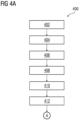
- FIG 4A-C is a flowchart of an method 400 for intelligent signal routing in an industrial communication network 100, in which an embodiment of the present invention can be implemented.
- FIG 4A-C is explained in conjunction with FIG 1 , 2 , and 3 .
- the signal mixer 202 receives the at least one field signal from at least one field device (104A, 104B, 104C, or 104D) of the plurality of field devices (104A-D).
- the signal mixer 202 superimposes the at least one unique ID on the received at least one field signal to generate a mixed signal.
- the signal mixer 202 superimposes the at least one unique ID on the at least one field signal by superimposing a high frequency signal on the at least one field signal.
- the high frequency signal is one of a analog or a digital signal which is superposed on the at least one field signal. In such a case, the high frequency signal comprises information associated with the at least one unique ID.
- the first request comprises information about a specific unique ID associated with the specific field device.
- the field signal marshal device 110 receives the first request from the input-output module 112.
- field signal marshal device 110 receives the mixed signal generated by the signal mixer 202, via the junction box device 108.
- the field signal marshal device 110 is connected to the junction box device 108 via one or more of the plurality of cables.
- the first input-output channel 114A transmits to the junction box device 108, the first request comprising the specific unique ID associated with the specific field signal.
- the first input-output channel 114A transmits the mixed signal to the input-output module 112.
- the junction box device 108 is connected to the connector device 106A-D and the field signal marshal device 110.
- the junction box device 108 comprises a first processing unit 206.
- the first processing unit 206 receives the first request from the field signal marshal device 110 and the mixed signal from the signal mixer 202.
- the first processing unit 206 extracts from the mixed signal, the at least one unique ID of the at least one field device 104A.
- the first processing unit 206 is further configured to compare the specific unique ID in the first request, with the at least one unique ID extracted from the mixed signal.
- the first processing unit 206 determines whether the specific unique ID matches with the at least one unique ID in the mixed signal.
- the first processing unit 206 routes the mixed signal associated with the at least one unique ID, to the first input-output channel 114A based on a determination that the specific unique ID matches with the at least one unique ID.
- the system 102 intelligently routes the at least one field signal to the first input-output channel 114A, based on the first request received from the input-output module.
- the at least one field signal is routed to the plurality of controllers automatically, without user intervention.
- time and effort required to perform cable engineering and hardwiring the plurality of field devices 104A-D to the plurality of controllers is reduced.
- the first processing unit 206 captures a signal from an active communication channel between a field device (such as the first field device 104A) of the plurality of field devices 104A-D and a second input-output channel 114B of the plurality of input-output channels 114A-D.
- the captured signal is the mixed signal generated by the signal mixer 202 of the connector device 106A-D.
- the first processing unit 206 extracts a unique ID from the signal captured from the active communication channel.
- the first processing unit 206 is configured to extract the unique ID by application of at least one signal processing filter on the captured signal.
- the at least one signal processing filter include a high-pass filter and a low-pass filter.
- the first processing unit 206 is configured to extract the unique ID by application of a decryption algorithm on the captured signal.
- the first processing unit 206 compares the extracted unique ID with each of the plurality of unique ID present in the look-up table. In a case where the extracted unique ID is present in the look-up table, the first processing unit 206 is configured to determine whether the extracted unique ID is mapped to the second input-output channel 114B of the plurality of input-output channels 114A-C. In a case where it is determined that, in the look-up table, the extracted unique ID is not mapped to the second input-output channel 114B, the first processing unit 202 is further configured to terminate the active communication channel.
- any active communication channel from incorrectly connected field devices of the plurality of field devices 104A-D are automatically terminated. Thus, the plurality of field devices 104A-D are protected from incorrect termination.
- the system 102 enables the commission engineer to reroute the at least one field signal to different controllers by simply modifying the look-up table.
- the first processing unit 206 analyzes the look-up table to determine whether the third input-output channel 114C of the plurality of input-output channels 114A-C is mapped to the extracted unique ID.
- the first processing unit 206 reroutes the captured signal to the determined third input-output channel 114C of the plurality of input-output channels 114A-C.
- any faults in connections between the plurality of field devices 104A-D and the plurality of input-output channels 114A-C are automatically rectified.
- the plurality of field devices 104A-D are protected from incorrect termination.
- the second processing unit 210 transmits a second request to the junction box device 108 via the first input-output channel 114A.
- the second request is to conduct a loop test of the first input-output channel 114A.
- the second processing unit 210 is further configured to determine whether the field signal marshal device 110 receives a response for the second request from the junction box device 108, within a specified time interval, via the first input-output channel 114A.
- the second processing unit 210 displays, based on a determination that the response is not received within the specific time interval, a notification that the first input-output channel 114A is faulty.
- the notification is displayed on the display device 212.
- the second processing unit 210 is further configured to transmit the second request for the loop test to the junction box device 108 via the second input-output channel 114B of the plurality of input-output channels 114A-C.
- the third processing unit 204 extracts, from the look-up table, the at least one unique ID associated with the at least one field device.
- the third processing unit 204 is further configured to generate the high frequency signal based on the extracted at least one unique ID.
- the present invention can take a form of a computer program product comprising program modules accessible from computer-usable or computer-readable medium storing program code for use by or in connection with one or more computers, processors, or instruction execution system.
- a computer-usable or computer-readable medium can be any apparatus that can contain, store, communicate, propagate, or transport the program for use by or in connection with the instruction execution system, apparatus, or device.
- the medium can be electronic, magnetic, optical, electromagnetic, infrared, or semiconductor system (or apparatus or device) or a propagation mediums in and of themselves as signal carriers are not included in the definition of physical computer-readable medium include a semiconductor or solid state memory, magnetic tape, a removable computer diskette, random access memory (RAM), a read only memory (ROM), a rigid magnetic disk and optical disk such as compact disk read-only memory (CD-ROM), compact disk read/write, and DVD.
- RAM random access memory
- ROM read only memory
- CD-ROM compact disk read-only memory
- DVD compact disk read/write
- Both processors and program code for implementing each aspect of the technology can be centralized or distributed (or a combination thereof) as known to those skilled in the art.
Landscapes
- Engineering & Computer Science (AREA)
- Computer Networks & Wireless Communication (AREA)
- Signal Processing (AREA)
- Health & Medical Sciences (AREA)
- Computing Systems (AREA)
- General Health & Medical Sciences (AREA)
- Medical Informatics (AREA)
- Small-Scale Networks (AREA)
Abstract
Description
- The present invention relates to a field of engineering of computer assisted engineering, and more particularly relates to a system, apparatus, and a method for intelligent signal routing in an industrial communication network.
- A technical installation comprises a plurality of field devices and a plurality of controllers which are communicatively coupled to each other via an industrial communication network. The technical installation is at least one of an industrial manufacturing plant, an industrial processing plant, or an industrial power plant. The plurality of field devices function together in the technical installation to achieve one or more objectives of the technical installation. Examples of the plurality of field devices comprises servers, robots, switches, automation devices, motors, valves, pumps, actuators, sensors and other industrial equipment(s). The plurality of controllers comprise programmable logic controllers (PLC)s, human machine interfaces (HMIs). Examples of the industrial communication network includes Ethernet, Modbus, Controlnet and the like.
- The plurality of field devices and the plurality of controllers communicate with each other via a plurality of cables of the industrial communication network. The plurality of cables comprises ethernet cables, robotic cables, sensor cables, multicore cables, and the like. The plurality of cables are implemented via a cable engineering process. The cable engineering process includes a list of activities associated with cable scheduling, cable routing, and cable termination associated with the plurality of cables in the industrial communication network.
- Typically, the technical installation comprises hundreds and thousands of field devices. It is a laboursome, timeconsuming, and difficult task for a commission engineer to manually implement a plurality of cable-based communication channels between each of the plurality of field devices and the plurality of controllers. Further, a few cables of the plurality of cables may be faulty. Since faulty cables lead to unscheduled downtimes, the faulty cables have to be identified by human operators via regular performance of loop testing in the plurality of cables. It is a laboursome, timeconsuming, and difficult task for the human operators to manually perform loop testing for each of the plurality of cables. Furthermore, in a case where the faulty cables are identified in the plurality of cables, it is difficult to replace the faulty cables with functioning cables without requiring extensive downtime. Furthermore, often, the plurality of cables are not terminated correctly by the commission engineer. Incorrect termination of the plurality of cables lead to unscheduled downtimes.
- Therefore, it is an object of the present invention to provide a system, apparatus, and method for intelligent signal routing in an industrial communication network.
- The object of the invention is achieved by a system for intelligent signal routing in an industrial communication network. The industrial communication network interconnects a plurality of field devices and a plurality of controllers in a technical installation. The technical installation is at least one of an industrial manufacturing plant, an industrial processing plant, or an industrial power plant. The plurality of field devices function together in the technical installation to achieve one or more objectives of the technical installation. Examples of the plurality of field devices comprises servers, robots, switches, automation devices, motors, valves, pumps, actuators, sensors and other industrial equipment(s). The plurality of controllers comprise programmable logic controllers (PLC)s, human machine interfaces (HMIs). Examples of the industrial communication network includes Ethernet, Modbus, Controlnet and the like. The plurality of field devices and the plurality of controllers communicate with each other via a plurality of cables of the industrial communication network.
- The plurality of cables comprises ethernet cables, robotic cables, sensor cables, multicore cables, and the like. In one example, each of the plurality of cables is a multi-core cable. The system comprises a connector device, a field signal marshal device, and a junction box device. The connector device is a device which is configured to carry field signals between a field device and the field signal marshal device. The field signal marshal device is a device which is configured to carry field signals from the connector device to the junction box device. The junction box device is configured to transmit the field signals to a programmable logic controller. The connector device is communicatively coupled with at least one field device of the plurality of field devices, via at least one cable of the plurality of cables. The at least one field device has at least one unique identification number (ID). The unique identification number is at least one an alphanumeric, hexadecimal, or a binary code to identify the at least one field device. Each of the plurality of field devices have one or more unique Ids. The at least one field device is configured to generate at least one field signal. The connector device receives the at least one field signal via the at least one cable connected to the at least one field device. The connector device is further communicatively coupled to the junction box device. The connector device is a device which is configured to receive, process and transmit the at least one field signal to the junction box device.
- The connector device comprises a signal mixer. The signal mixer is at least one of an active mixer and a passive mixer. The signal mixer is at least one of a balanced mixer and an unbalanced mixer. The signal mixer is configured to receive the at least one field signal from the at least one field device. The signal mixer is further configured to superimpose the at least one unique ID on the received at least one field signal to generate a mixed signal. In one example, the signal mixer superimposes the at least one unique ID on the at least one field signal by superimposing a high frequency signal on the at least one field signal. In such a case, the high frequency signal comprises information associated with the at least one unique ID.
- In the preferred embodiment, the field signal marshal device is communicatively coupled to an input-output module and the junction box device. The input output module is connected to one or more of the plurality of controllers. The one or more of the plurality of controllers generate a first request for a specific field signal from a specific field device of the plurality of field devices. The first request comprises information about a specific unique ID associated with the specific field device. The field signal marshal device is configured to receive the first request from the input-output module. Further, the field signal marshal device is configured to receive the mixed signal generated by the signal mixer, via the junction box device. The field signal marshal device is connected to the junction box device via one or more of the plurality of cables.
- In the preferred embodiment, the field signal marshal device further comprises a first input-output channel. In one example, the first input-output channel is connected to the plurality of cables, on one end and is connected to the input-output module on the other end. The first input-output channel is configured to transmit to the junction box device, the first request comprising the specific unique ID associated with the specific field signal. The first input-output channel is further configured to transmit the mixed signal to the input-output module.
- In the preferred embodiment, the junction box device is connected to the connector device and the field signal marshal device. The junction box device comprises a first processing unit. The first processing unit, as used herein, means any type of computational circuit, such as, but not limited to, a microprocessor unit, microcontroller, complex instruction set computing microprocessor unit, reduced instruction set computing microprocessor unit, very long instruction word microprocessor unit, explicitly parallel instruction computing microprocessor unit, graphics processing unit, digital signal processing unit, or any other type of processing circuit. The first processing unit may also include embedded controllers, such as generic or programmable logic devices or arrays, application specific integrated circuits, single-chip computers, and the like. The first processing unit is configured to receive, the first request from the field signal marshal device and the mixed signal from the signal mixer.
- In the preferred embodiment, the first processing unit is further configured to extract, from the mixed signal, the at least one unique ID of the at least one field device. The first processing unit is further configured to compare the specific unique ID in the first request, with the at least one unique ID extracted from the mixed signal. The first processing unit is further configured to determine whether the specific unique ID matches with the at least one unique ID in the mixed signal. The first processing unit is further configured to route the mixed signal associated with the at least one unique ID, to the first input-output channel based on a determination that the specific unique ID matches with the at least one unique ID. Advantageously, the system intelligently routes the at least one field signal to the first input-output channel, based on the first request received from the input-output module. Thus, the at least one field signal is routed to the plurality of controllers automatically, without user intervention. Furthermore, time and effort required to perform cable engineering and hardwiring the plurality of field devices to the plurality of controllers is reduced. Furthermore, the system enables the commission engineer to reroute the at least one field devices to different controllers of the plurality of controllers, without making hardware changes
- In the preferred embodiment, the system further comprises a memory. The memory may be non-transitory volatile memory and non-volatile memory. The memory may be coupled for communication with the first processing unit, such as being a computer-readable storage medium. The first processing unit may execute machine-readable instructions and/or source code stored in the memory. A variety of machine-readable instructions may be stored in and accessed from the
memory 204. The memory may include any suitable elements for storing data and machine-readable instructions, such as read only memory, random access memory, erasable programmable read only memory, electrically erasable programmable read only memory, a hard drive, a removable media drive for handling compact disks, digital video disks, diskettes, magnetic tape cartridges, memory cards, and the like. In the present embodiment, the memory includes an integrated development environment (IDE). The IDE includes an automation module stored in the form of machine-readable instructions on any of the above-mentioned storage media and may be in communication with and executed by the first processing unit. The memory is further configured to store a look-up table. The look-up table comprises information associated with a plurality of mappings between a plurality of unique IDs and a plurality of input-output channels of the field signal marshal device associated with a plurality of field devices connected to the industrial communication network. The plurality of mappings in the look-up table denotes correct mapping of the plurality of field devices to the plurality of input-output channels. - In the preferred embodiment, the first processing unit is further configured to capture a signal from an active communication channel between a field device of the plurality of field devices and a second input-output channel of the plurality of input-output channels. In one example, the captured signal is the mixed signal generated by the signal mixer of the connector device.
- In the preferred embodiment, the first processing unit is further configured to extract a unique ID from the signal captured from the active communication channel. In one example, the first processing unit is configured to extract the unique ID by application of at least one signal processing filter on the captured signal. Examples of the at least one signal processing filter include a high-pass filter and a low-pass filter. In another example, the first processing unit is configured to extract the unique ID by application of a decryption algorithm on the captured signal.
- In the preferred embodiment, the first processing unit is further configured to compare the extracted unique ID with each of the plurality of unique ID present in the look-up table. In a case where the extracted unique ID is present in the look-up table, the first processing unit is configured to determine whether the extracted unique ID is mapped to the second input-output channel of the plurality of input-output channels. In a case where it is determined that, in the look-up table, the extracted unique ID is not mapped to the second input-output channel, the first processing unit is further configured to terminate the active communication channel. Advantageously, any active communication channel from incorrectly connected field devices of the plurality of field devices are automatically terminated. Thus, the plurality of field devices are protected from incorrect termination.
- Further, the first processing unit is further configured to analyze the look-up table to determine whether a third input-output channel of the plurality of input-output channels which is mapped to the extracted unique ID. The first processing unit is further configured to reroute the captured signal to the determined third input-output channel of the plurality of input-output channels. Advantageously, any faults in connections between the plurality of field devices and the plurality of input-output channels are automatically rectified. Thus, the plurality of field devices are protected from incorrect termination.
- In a preferred embodiment, the field signal marshal device further comprises a second processing unit. The second processing unit may be similar in structure and functionality as the first processing unit. The second processing unit is configured to transmit a second request to the junction box device via the first input-output channel. The second request is to conduct a loop test of the first input-output channel. The second processing unit is further configured to determine whether the field signal marshal device receives a response for the second request from the junction box device, within a specified time interval, via the first input-output channel.
- The second processing unit is further configured to display, based on a determination that the response is not received within the specific time interval, a notification that the first input-output channel is faulty. The notification is displayed on a display device. The second processing unit is further configured to transmit the second request for the loop test to the junction box device via the second input-output channel of the plurality of input-output channels.
- In a preferred embodiment, the connector device further comprises a third processing unit which is configured to extract, from the look-up table, the at least one unique ID associated with the at least one field device. The third processing unit is further configured to generate the high frequency signal based on the extracted at least one unique ID.
- The object of the invention is achieved by an apparatus for intelligent signal routing in an industrial communication network. The apparatus for intelligent signal routing in an industrial communication network comprises a signal mixer, a first processing unit, and a first input-output channel. The signal mixer is further configured to receive at least one field signal from the at least one field device. The at least one field device has at least one unique ID. The signal mixer is further configured to superimpose the at least one unique ID on the received at least one field signal to generate a mixed signal.
- The first input-output channel is configured to transmit to the signal mixer, a first request comprising a specific unique ID associated with a specific field signal. The first input-output channel is configured to transmit the mixed signal to an input-output module. The first processing unit is configured to receive, the first request from the first input-output channel and the mixed signal from the signal mixer.
- The first processing unit is further configured to extract the at least one unique ID from the mixed signal. The first processing unit is further configured to determine whether the specific unique ID matches with the at least one unique ID associated with the at least one field device. The first processing unit is further configured to route the mixed signal associated with the at least one unique ID, to the first input-output channel based on a determination that the specific unique ID matches with the at least one unique ID associated with the at least one field device.
- In a preferred embodiment, the apparatus further comprises a memory which is configured to store a look-up table. The look-up table comprises information associated with mappings between a plurality of unique IDs associated with a plurality of field devices in the industrial communication network, and a plurality of input-output channels of the field signal marshal device.
- In the preferred embodiment, the first processing unit is further configured to capture a signal from an active communication channel between a field device of the plurality of field devices and a second input-output channel of the plurality of input-output channels. The first processing unit is further configured to extract a unique ID from the signal captured from the active communication channel. The first processing unit is further configured to analyze the look-up table to determine whether, in the look-up table, the extracted unique ID is mapped to the second input-output channel of the plurality of input-output channels. The first processing unit is further configured to terminate the active communication channel based on a determination that the extracted unique ID is not mapped to the second input-output channel of the plurality of input-output channels.
- In the preferred embodiment, the first processing unit is further configured to analyze the look-up table to determine a third input-output channel of the plurality of input-output channels, into which the extracted unique ID is mapped. The first processing unit is further configured to reroute the captured signal to the determined third input-output channel of the plurality of input-output channels.
- In the preferred embodiment, the apparatus further comprising a second input-output channel and a second processing unit. The second processing unit is configured to transmit a second request to the junction box device via the first input-output channel. The second request is for conducting a loop test of the first input-output channel. The second processing unit is further configured to determine whether the field signal marshal device receives a response for the second request from the junction box device, within a specified time interval, via the first input-output channel. The second processing unit is further configured to display, based on a determination that the response is not received within the specific time interval, a notification that the first input-output channel is faulty. The second processing unit is further configured to transmit the second request for the loop test to the junction box device via the second input-output channel.
- In the preferred embodiment, the apparatus further comprises a third processing unit configured to extract, from the look-up table, the at least one unique ID associated with the at least one field device. The third processing unit is further configured to generate the high frequency signal based on the extracted at least one unique ID, wherein the at least one unique ID is superimposed on the at least one field signal by mixing the high frequency signal with the at least one field signal.
- The object of the invention is further achieved by a method for intelligent signal routing in an industrial communication network. The method of intelligent signal routing in an industrial communication network is executed in a system comprising a signal mixer, a first input-output channel, and a first processing unit.
- In the preferred embodiment, the method comprises receiving, by the signal mixer, at least one field signal from the at least one field device. The at least one field device has at least one unique ID. The method further comprises superimposing, by the signal mixer, the at least one unique ID on the received at least one field signal to generate a mixed signal. The method further comprises transmitting via the first input-output channel to a junction box device, a first request comprising a specific unique ID associated with a specific field signal. The method further comprises extracting, by the first processing unit, the at least one unique ID from the mixed signal. The method further comprises determining, by the first processing unit, whether the specific unique ID matches with the at least one unique ID associated with the at least one field device. The method further comprises routing, by the first processing unit, the mixed signal associated with the at least one unique ID, to the first input-output channel based on a determination that the specific unique ID matches with the at least one unique ID associated with the at least one field device.
- In the preferred embodiment, the method further comprises capturing, by the first processing unit, a signal from an active communication channel between a field device of a plurality of field devices and a second input-output channel of a plurality of input-output channels. The method further comprises extracting, by the first processing unit, a unique ID from the signal captured from the active communication channel.
- The method further comprises analyzing, by the first processing unit, a look-up table to determine whether, in the look-up table, the extracted unique ID is mapped to the second input-output channel of the plurality of input-output channels. The method further comprises terminating, by the first processing unit, the active communication channel based on a determination that the extracted unique ID is not mapped to the second input-output channel of the plurality of input-output channels.
- In the preferred embodiment, the method further comprises analyzing, by the first processing unit, the look-up table to determine a third input-output channel of the plurality of input-output channels, into which the extracted unique ID is mapped. The method further comprises rerouting, by the first processing unit, the captured signal to the determined third input-output channel of the plurality of input-output channels.
- In the preferred embodiment, the method further comprises transmitting, by the first processing unit, a second request to the junction box device via the first input-output channel. The second request is for conducting a loop test of the first input-output channel. The method further comprises determining, by the first processing unit, whether the field signal marshal device receives a response for the second request from the junction box device, within a specified time interval, via the first input-output channel.
- The method further comprises displaying, by the first processing unit, based on a determination that the response is not received within the specific time interval, a notification that the first input-output channel is faulty. The method further comprises transmitting, by the first processing unit, the second request for the loop test to the junction box device via the second input-output channel.
- In the preferred embodiment, the method further comprises extracting, by the first processing unit, from the look-up table, the at least one unique ID associated with the at least one field device. The method further comprises generating, by the first processing unit, the high frequency signal based on the extracted at least one unique ID, wherein the at least one unique ID is superimposed on the at least one field signal by mixing the high frequency signal with the at least one field signal.
- The above-mentioned and other features of the invention will now be addressed with reference to the accompanying drawings of the present invention. The illustrated embodiments are intended to illustrate, but not limit the invention.
- The present invention is further described hereinafter with reference to illustrated embodiments shown in the accompanying drawings, in which:
- FIG 1
- is a block diagram of an system for intelligent signal routing in an industrial communication network, according to an embodiment of the present invention;
- FIG 2
- is a block diagram of the system, such as that shown in
FIG. 1 , in which an embodiment of the present invention can be implemented; - FIG 3
- is a block diagram of an apparatus for intelligent signal routing in an industrial communication network, in which an embodiment of the present invention can be implemented; and
- FIG 4A-C
- is a flowchart of an method for intelligent signal routing in an industrial communication network, in which an embodiment of the present invention can be implemented.
- Various embodiments are described with reference to the drawings, wherein like reference numerals are used to refer the drawings, wherein like reference numerals are used to refer to like elements throughout. In the following description, for the purpose of explanation, numerous specific details are set forth in order to provide thorough understanding of one or more embodiments. It may be evident that such embodiments may be practiced without these specific details.
-
FIG 1 is a block diagram of asystem 102 for intelligent signal routing in anindustrial communication network 100, according to an embodiment of the present invention. Theindustrial communication network 100 interconnects a plurality offield devices 104A-D and an input-output module 112 of a plurality of controllers in a technical installation. - The technical installation is at least one of an industrial manufacturing plant, an industrial processing plant, or an industrial power plant. The plurality of
field devices 104A-D function together in the technical installation to achieve one or more objectives of the technical installation. Exampies of the plurality offield devices 104A-D comprises servers, robots, switches, automation devices, motors, valves, pumps, actuators, sensors and other industrial equipment(s). The plurality of controllers comprise programmable logic controllers (PLC)s, human machine interfaces (HMIs). Examples of theindustrial communication network 100 includes Ethernet, Modbus, Controlnet and the like. The plurality offield devices 104A-D and the plurality of controllers communicate with each other via a plurality of cables of theindustrial communication network 100. - The plurality of cables comprises ethernet cables, robotic cables, sensor cables, multicore cables, and the like. In one example, each of the plurality of cables is a multi-core cable. The
system 102 comprises at least oneconnector device 106A-D, a fieldsignal marshal device 110, and ajunction box device 108. Theconnector device 106A-D is communicatively coupled with at least one field device of the plurality offield devices 104A-D, via at least one cable of the plurality of cables. The at least one field device has at least one unique identification number (ID). The unique identification number is at least one an alphanumeric, hexadecimal, or a binary code to identify the at least one field device. Each of the plurality offield devices 104A-D have one or more unique Ids. The at least one field device is configured to generate at least one field signal. Theconnector device 106A-D receives the at least one field signal via the at least one cable connected to the at least one field device. Theconnector device 106A-D is further communicatively coupled to thejunction box device 108. Theconnector device 106A-D is a device which is configured to receive, process and transmit the at least one field signal to thejunction box device 108. The fieldsignal marshal device 110 is communicatively coupled to theinput output module 112 and thejunction box device 108. Theinput output module 112 is connected to one or more of the plurality of controllers. The one or more of the plurality of controllers generate a first request for a specific field signal from a specific field device of the plurality offield devices 104A-D. Thesystem 102 further comprises amemory 116. Thememory 116 may be non-transitory volatile memory and non-volatile memory. -
FIG 2 is a block diagram of the system, such as that shown inFIG 1 , in which an embodiment of the present invention can be implemented.FIG 2 is explained in conjunction with elements ofFIG 1 . - The
connector device 106A-D comprises asignal mixer 202. Thesignal mixer 202 is at least one of an active mixer, a passive mixer, a balanced mixer or an unbalanced mixer. Thesignal mixer 202 is configured to receive the at least one field signal from at least one field device (104A, 104B, 104C, or 104D) of the plurality of field devices (104A-D). Thesignal mixer 202 is further configured to superimpose the at least one unique ID on the received at least one field signal to generate a mixed signal. In one example, thesignal mixer 202 superimposes the at least one unique ID on the at least one field signal by superimposing a high frequency signal on the at least one field signal. In such a case, the high frequency signal comprises information associated with the at least one unique ID. - The first request comprises information about a specific unique ID associated with the specific field device. The field
signal marshal device 110 is configured to receive the first request from the input-output module 112. Further, the fieldsignal marshal device 110 is configured to receive the mixed signal generated by thesignal mixer 202, via thejunction box device 108. The fieldsignal marshal device 110 is connected to thejunction box device 108 via one or more of the plurality of cables. - The field
signal marshal device 110 further comprises a first input-output channel 114A of a plurality of input-output channels 114A-C. In one example, the first input-output channel 114A is connected to the plurality of cables, on one end and is connected to the input-output module 112 on the other end. The first input-output channel 114A is configured to transmit to thejunction box device 108, the first request comprising the specific unique ID associated with the specific field signal. The first input-output channel 114A is further configured to transmit the mixed signal to the input-output module 112. - The
junction box device 108 is connected to theconnector device 106A-D and the fieldsignal marshal device 110. Thejunction box device 108 comprises afirst processing unit 206. Thefirst processing unit 206, as used herein, means any type of computational circuit, such as, but not limited to, a microprocessor unit, microcontroller, complex instruction set computing microprocessor unit, reduced instruction set computing microprocessor unit, very long instruction word microprocessor unit, explicitly parallel instruction computing microprocessor unit, graphics processing unit, digital signal processing unit, or any other type of processing circuit. Thefirst processing unit 206 may also include embedded controllers, such as generic or programmable logic devices or arrays, application specific integrated circuits, single-chip computers, and the like. Thefirst processing unit 206 is configured to receive, the first request from the fieldsignal marshal device 110 and the mixed signal from thesignal mixer 202. - The
first processing unit 206 is further configured to extract, from the mixed signal, the at least one unique ID of the at least onefield device 104A. Thefirst processing unit 206 is further configured to compare the specific unique ID in the first request, with the at least one unique ID extracted from the mixed signal. Thefirst processing unit 206 is further configured to determine whether the specific unique ID matches with the at least one unique ID in the mixed signal. Thefirst processing unit 206 is further configured to route the mixed signal associated with the at least one unique ID, to the first input-output channel 114A based on a determination that the specific unique ID matches with the at least one unique ID. Advantageously, the system intelligently routes the at least one field signal to the first input-output channel 114A, based on the first request received from the input-output module. Thus, the at least one field signal is routed to the plurality of controllers automatically, without user intervention. Furthermore, time and effort required to perform cable engineering and hardwiring the plurality offield devices 104A-D to the plurality of controllers is reduced. - In one example, the
junction box device 108 further comprises ademultiplexer 208. In such a case, theprocessing unit 206 is configured to route the mixed signal by using thedemultiplexer 208. - The memory may be coupled for communication with the
first processing unit 206, such as being a computer-readable storage medium. Thefirst processing unit 206 may execute machine-readable instructions and/or source code stored in the memory. A variety of machine-readable instructions may be stored in and accessed from thememory 116. The memory may include any suitable elements for storing data and machine-readable instructions, such as read only memory, random access memory, erasable programmable read only memory, electrically erasable programmable read only memory, a hard drive, a removable media drive for handling compact disks, digital video disks, diskettes, magnetic tape cartridges, memory cards, and the like. In the present embodiment, the memory includes an integrated development environment (IDE). The IDE includes an automation module stored in the form of machine-readable instructions on any of the above-mentioned storage media and may be in communication with and executed by thefirst processing unit 206. The memory is further configured to store a look-up table. The look-up table comprises information associated with a plurality of mappings between a plurality of unique IDs and the plurality of input-output channels 114A-C of the fieldsignal marshal device 110 associated with the plurality offield devices 104A-D connected to theindustrial communication network 100. The plurality of mappings in the look-up table denotes correct mapping of the plurality offield devices 104A-D to the plurality of input-output channels 114A-C. - The
first processing unit 206 is further configured to capture a signal from an active communication channel between a field device (such as thefirst field device 104A) of the plurality offield devices 104A-D and a second input-output channel 114B of the plurality of input-output channels 114A-D. In one example, the captured signal is the mixed signal generated by thesignal mixer 202 of theconnector device 106A-D. - The
first processing unit 206 is further configured to extract a unique ID from the signal captured from the active communication channel. In one example, thefirst processing unit 206 is configured to extract the unique ID by application of at least one signal processing filter on the captured signal. Examples of the at least one signal processing filter include a high-pass filter and a low-pass filter. In another example, thefirst processing unit 206 is configured to extract the unique ID by application of a decryption algorithm on the captured signal. - The
first processing unit 206 is further configured to compare the extracted unique ID with each of the plurality of unique ID present in the look-up table. In a case where the extracted unique ID is present in the look-up table, thefirst processing unit 206 is configured to determine whether the extracted unique ID is mapped to the second input-output channel 114B of the plurality of input-output channels 114A-C. In a case where it is determined that, in the look-up table, the extracted unique ID is not mapped to the second input-output channel 114B, thefirst processing unit 202 is further configured to terminate the active communication channel. Advantageously, any active communication channel from incorrectly connected field devices of the plurality offield devices 104A-D are automatically terminated. Thus, the plurality offield devices 104A-D are protected from incorrect termination. Furthermore, thesystem 102 enables the commission engineer to reroute the at least one field signal to different controllers by simply modifying the look-up table. - Further, the
first processing unit 206 is further configured to analyze the look-up table to determine whether a third input-output channel 114C of the plurality of input-output channels 114A-C which is mapped to the extracted unique ID. Thefirst processing unit 206 is further configured to reroute the captured signal to the determined third input-output channel 114C of the plurality of input-output channels 114A-C. Advantageously, any faults in connections between the plurality offield devices 104A-D and the plurality of input-output channels 114A-C are automatically rectified. Thus, the plurality offield devices 104A-D are protected from incorrect termination. - The field
signal marshal device 110 further comprises asecond processing unit 210. Thesecond processing unit 210 may be similar in structure and functionality as thefirst processing unit 206. Thesecond processing unit 210 is configured to transmit a second request to the junction box device via the first input-output channel 114A. The second request is to conduct a loop test of the first input-output channel 114A. Thesecond processing unit 210 is further configured to determine whether the fieldsignal marshal device 110 receives a response for the second request from thejunction box device 108, within a specified time interval, via the first input-output channel 114A. - The
second processing unit 210 is further configured to display, based on a determination that the response is not received within the specific time interval, a notification that the first input-output channel 114A is faulty. The notification is displayed on adisplay device 212. In one example, the display device is a liquid crystal display device. Thesecond processing unit 210 is further configured to transmit the second request for the loop test to thejunction box device 108 via the second input-output channel 114B of the plurality of input-output channels 114A-C. - The
connector device 106A-D further comprises athird processing unit 204 which is configured to extract, from the look-up table, the at least one unique ID associated with the at least one field device. Thethird processing unit 204 is further configured to generate the high frequency signal based on the extracted at least one unique ID. -
FIG 3 is a block diagram of anapparatus 300 for intelligent signal routing in anindustrial communication network 100, in which an embodiment of the present invention can be implemented. - The
apparatus 300 for intelligent signal routing in theindustrial communication network 100 comprises asignal mixer 302, aprocessing unit 304, and a plurality of input-output channels 114A-C. Thesignal mixer 302 is further configured to receive at least one field signal from at least onefield device 104A of the plurality offield devices 104A-D. The at least one field device has at least one unique ID. Thesignal mixer 302 is further configured to superimpose the at least one unique ID on the received at least one field signal to generate a mixed signal. - A first input-
output channel 114A is configured to transmit to thesignal mixer 302, a first request comprising a specific unique ID associated with a specific field signal. The first input-output channel is further configured to transmit the mixed signal to the input-output module 112. Thefirst processing unit 304 is configured to receive, the first request from the first input-output channel 114A and the mixed signal from thesignal mixer 302. - The
first processing unit 304 is further configured to extract the at least one unique ID from the mixed signal. Thefirst processing unit 304 is further configured to determine whether the specific unique ID matches with the at least one unique ID associated with the at least onefield device 104A. Thefirst processing unit 304 is further configured to route the mixed signal associated with the at least one unique ID, to the first input-output channel 114A based on a determination that the specific unique ID matches with the at least one unique ID associated with the at least onefield device 104A. - The
apparatus 300 further comprises thememory 116 which is configured to store a look-up table. The look-up table comprises information associated with mappings between a plurality of unique IDs associated with the plurality offield devices 104A-D in theindustrial communication network 100, and the plurality of input-output channels 114A-C. - The
first processing unit 304 is further configured to capture a signal from an active communication channel between afield device 104A of the plurality offield devices 104A-D and a second input-output channel 114B of the plurality of input-output channels 114A-C. Thefirst processing unit 304 is further configured to extract a unique ID from the signal captured from the active communication channel. Thefirst processing unit 304 is further configured to analyze the look-up table to determine whether, in the look-up table, the extracted unique ID is mapped to the second input-output channel 114B of the plurality of input-output channels 114A-C. Thefirst processing unit 304 is further configured to terminate the active communication channel based on a determination that the extracted unique ID is not mapped to the second input-output channel 114B of the plurality of input-output channels 114A-C. - The
first processing unit 304 is further configured to analyze the look-up table to determine a third input-output channel 114C of the plurality of input-output channels 114A-C, into which the extracted unique ID is mapped. Thefirst processing unit 304 is further configured to reroute the captured signal to the determined third input-output channel 114C of the plurality of input-output channels 114A-C. - The
apparatus 300 further comprises asecond processing unit 308 which is further configured to transmit a second request to the first input-output channel 114A for conducting a loop test of the first input-output channel 114A. Thesecond processing unit 308 is further configured to determine whether the first input-output channel receives a response from thefirst processing unit 304, within a specified time interval. Thesecond processing unit 308 is further configured to display, based on a determination that the response is not received within the specific time interval, a notification that the first input-output channel 114A is faulty. Thesecond processing unit 308 is further configured to transmit the second request for the loop test to thefirst processing unit 304 via the second input-output channel 114B. - The
first processing unit 304 is further configured to extract, from the look-up table, the at least one unique ID associated with the at least one field device. The third processing unit is further configured to generate the high frequency signal based on the extracted at least one unique ID, wherein the at least one unique ID is superimposed on the at least one field signal by mixing the high frequency signal with the at least one field signal. -
FIG 4A-C is a flowchart of anmethod 400 for intelligent signal routing in anindustrial communication network 100, in which an embodiment of the present invention can be implemented.FIG 4A-C is explained in conjunction withFIG 1 ,2 , and3 . - At
step 402, thesignal mixer 202 receives the at least one field signal from at least one field device (104A, 104B, 104C, or 104D) of the plurality of field devices (104A-D). Atstep 404, thesignal mixer 202 superimposes the at least one unique ID on the received at least one field signal to generate a mixed signal. In one example, thesignal mixer 202 superimposes the at least one unique ID on the at least one field signal by superimposing a high frequency signal on the at least one field signal. The high frequency signal is one of a analog or a digital signal which is superposed on the at least one field signal. In such a case, the high frequency signal comprises information associated with the at least one unique ID. - The first request comprises information about a specific unique ID associated with the specific field device. At
step 406, the fieldsignal marshal device 110 receives the first request from the input-output module 112. Atstep 408, fieldsignal marshal device 110 receives the mixed signal generated by thesignal mixer 202, via thejunction box device 108. The fieldsignal marshal device 110 is connected to thejunction box device 108 via one or more of the plurality of cables. - At
step 410, the first input-output channel 114A transmits to thejunction box device 108, the first request comprising the specific unique ID associated with the specific field signal. Atstep 412, the first input-output channel 114A transmits the mixed signal to the input-output module 112. - The
junction box device 108 is connected to theconnector device 106A-D and the fieldsignal marshal device 110. Thejunction box device 108 comprises afirst processing unit 206. Atstep 414, thefirst processing unit 206 receives the first request from the fieldsignal marshal device 110 and the mixed signal from thesignal mixer 202. - At
step 412, thefirst processing unit 206 extracts from the mixed signal, the at least one unique ID of the at least onefield device 104A. Thefirst processing unit 206 is further configured to compare the specific unique ID in the first request, with the at least one unique ID extracted from the mixed signal. At 414, thefirst processing unit 206 determines whether the specific unique ID matches with the at least one unique ID in the mixed signal. At 416, thefirst processing unit 206 routes the mixed signal associated with the at least one unique ID, to the first input-output channel 114A based on a determination that the specific unique ID matches with the at least one unique ID. Advantageously, thesystem 102 intelligently routes the at least one field signal to the first input-output channel 114A, based on the first request received from the input-output module. Thus, the at least one field signal is routed to the plurality of controllers automatically, without user intervention. Furthermore, time and effort required to perform cable engineering and hardwiring the plurality offield devices 104A-D to the plurality of controllers is reduced. - At 416, the
first processing unit 206 captures a signal from an active communication channel between a field device (such as thefirst field device 104A) of the plurality offield devices 104A-D and a second input-output channel 114B of the plurality of input-output channels 114A-D. In one example, the captured signal is the mixed signal generated by thesignal mixer 202 of theconnector device 106A-D. - At 418, the
first processing unit 206 extracts a unique ID from the signal captured from the active communication channel. In one example, thefirst processing unit 206 is configured to extract the unique ID by application of at least one signal processing filter on the captured signal. Examples of the at least one signal processing filter include a high-pass filter and a low-pass filter. In another example, thefirst processing unit 206 is configured to extract the unique ID by application of a decryption algorithm on the captured signal. - At 420, the
first processing unit 206 compares the extracted unique ID with each of the plurality of unique ID present in the look-up table. In a case where the extracted unique ID is present in the look-up table, thefirst processing unit 206 is configured to determine whether the extracted unique ID is mapped to the second input-output channel 114B of the plurality of input-output channels 114A-C. In a case where it is determined that, in the look-up table, the extracted unique ID is not mapped to the second input-output channel 114B, thefirst processing unit 202 is further configured to terminate the active communication channel. Advantageously, any active communication channel from incorrectly connected field devices of the plurality offield devices 104A-D are automatically terminated. Thus, the plurality offield devices 104A-D are protected from incorrect termination. Furthermore, thesystem 102 enables the commission engineer to reroute the at least one field signal to different controllers by simply modifying the look-up table. - At 422, the
first processing unit 206 analyzes the look-up table to determine whether the third input-output channel 114C of the plurality of input-output channels 114A-C is mapped to the extracted unique ID. At 424, thefirst processing unit 206 reroutes the captured signal to the determined third input-output channel 114C of the plurality of input-output channels 114A-C. Advantageously, any faults in connections between the plurality offield devices 104A-D and the plurality of input-output channels 114A-C are automatically rectified. Thus, the plurality offield devices 104A-D are protected from incorrect termination. - At
step 426, thesecond processing unit 210 transmits a second request to thejunction box device 108 via the first input-output channel 114A. The second request is to conduct a loop test of the first input-output channel 114A. Thesecond processing unit 210 is further configured to determine whether the fieldsignal marshal device 110 receives a response for the second request from thejunction box device 108, within a specified time interval, via the first input-output channel 114A. - At
step 428, thesecond processing unit 210 displays, based on a determination that the response is not received within the specific time interval, a notification that the first input-output channel 114A is faulty. The notification is displayed on thedisplay device 212. Thesecond processing unit 210 is further configured to transmit the second request for the loop test to thejunction box device 108 via the second input-output channel 114B of the plurality of input-output channels 114A-C. - At
step 430, thethird processing unit 204 extracts, from the look-up table, the at least one unique ID associated with the at least one field device. Thethird processing unit 204 is further configured to generate the high frequency signal based on the extracted at least one unique ID. - The present invention can take a form of a computer program product comprising program modules accessible from computer-usable or computer-readable medium storing program code for use by or in connection with one or more computers, processors, or instruction execution system. For the purpose of this description, a computer-usable or computer-readable medium can be any apparatus that can contain, store, communicate, propagate, or transport the program for use by or in connection with the instruction execution system, apparatus, or device. The medium can be electronic, magnetic, optical, electromagnetic, infrared, or semiconductor system (or apparatus or device) or a propagation mediums in and of themselves as signal carriers are not included in the definition of physical computer-readable medium include a semiconductor or solid state memory, magnetic tape, a removable computer diskette, random access memory (RAM), a read only memory (ROM), a rigid magnetic disk and optical disk such as compact disk read-only memory (CD-ROM), compact disk read/write, and DVD. Both processors and program code for implementing each aspect of the technology can be centralized or distributed (or a combination thereof) as known to those skilled in the art.
- While the present invention has been described in detail with reference to certain embodiments, it should be appreciated that the present invention is not limited to those embodiments. In view of the present disclosure, many modifications and variations would be present themselves, to those skilled in the art without departing from the scope of the various embodiments of the present invention, as described herein. The scope of the present invention is, therefore, indicated by the following claims rather than by the foregoing description. All changes, modifications, and variations coming within the meaning and range of equivalency of the claims are to be considered within their scope. All advantageous embodiments claimed in method claims may also be apply to system/apparatus claims.
-
- 1. an
industrial environment 100 - 2. an
engineering system 102 - 3. one or more client devices 120A-N
- 4. a network 104
- 5. one or more engineering objects 108A-N
- 6. one or more client devices 120A-N
- 7. a
platform 110 - 8. an
automation module 112 - 9. a server 114
- 10. a
network interface 116 - 11. a database 118
- 12. a processor(s) 202
- 13. an
accessible memory 204 - 14. a
storage unit 206 - 15. a
communication interface 208 - 16. an input-
output unit 210 - 17. a
network interface 212 - 18. a bus 214
- 19. an integrated development environment (IDE) 216
- 20. a
request handler module 302, - 21. an object behavior
model generation module 304, - 22. an analysis module 306,
- 23. a
modifier module 308 - 24. an engineering object database 310
- 25. a validation module 312
- 26. a deployment module 314.
Claims (15)
- A system (102) for intelligent signal routing in an industrial communication network (100), the system (102) comprising:a connector device (106A-D) comprising a signal mixer (202), wherein the signal mixer (202) is configured to:receive at least one field signal from the at least one field device (104A), wherein the at least one field device (104A) has at least one unique identification number (ID); andsuperimpose the at least one unique ID on the received at least one field signal to generate a mixed signal;a field signal marshal device (110) comprising a first input-output channel (114A), wherein the first input-output channel (114A) is configured to:transmit to a junction box device (108), a first request comprising a specific unique ID associated with a specific field signal; andtransmit the mixed signal to an input-output module (112); andthe junction box device (108) comprising a first processing unit (206), wherein the first processing unit (206) is configured to:receive, the first request from the field signal marshal device (110) and the mixed signal from the signal mixer (202);determine whether the specific unique ID matches with the at least one unique ID in the mixed signal; androute the mixed signal associated with the at least one unique ID, to the first input-output channel (114A) based on a determination that the specific unique ID matches with the at least one unique ID.
- The system (102) according to claim 1, further comprising a memory (116) configured to store a look-up table,wherein the look-up table comprises information associated with a plurality of mappings between:a plurality of unique IDs associated with a plurality of field devices (104A-D) connected to the industrial communication network (100), anda plurality of input-output channels (114A-C) of the field signal marshal device (110), andwherein the first processing unit (206) is further configured to:capture a signal from an active communication channel between a field device (104A) of the plurality of field devices (104A-D) and a second input-output channel (114B) of the plurality of input-output channels (114A-C);extract a unique ID from the signal captured from the active communication channel;analyze the plurality of mappings in the look-up table to determine whether the extracted unique ID is mapped to the second input-output channel (114B) of the plurality of input-output channels (114A-C); andterminate the active communication channel based on a determination that the extracted unique ID is not mapped to the second input-output channel (114B) of the plurality of input-output channels (114A-C).
- The system (102) according to claim 2, wherein the first processing unit (206) is further configured to:analyze the plurality of mappings of the look-up table to determine a third input-output channel (114C) of the plurality of input-output channels (114C) which is mapped to the extracted unique ID; andreroute the captured signal to the determined third input-output channel (114C) of the plurality of input-output channels (114A-C).
- The system (102) according to claims 1 to 3, wherein the field signal marshal device (110) further comprises a second processing unit (210), wherein the second processing unit (210) is configured to:transmit a second request to the junction box device (108) via the first input-output channel (114A), wherein the second request is for a loop test of the first input-output channel (114A);determine whether the field signal marshal device (110) receives a response for the second request from the junction box device (108), within a specified time interval, via the first input-output channel (114A); anddisplay, based on a determination that the response is not received within the specific time interval, a notification that the first input-output channel (114A) is faulty; andtransmit the second request for the loop test to the junction box device (108) via the second input-output channel (114B) of the plurality of input-output channels (114A-C).
- The system (102) according to claims 2 to 4,wherein the connector device (106A-D) further comprises a third processing unit (204) which is configured to:extract, from the look-up table, the at least one unique ID associated with the at least one field device; andgenerate a high frequency signal based on the extracted at least one unique ID; andwherein the at least one unique ID is superimposed on the at least one field signal by mixing the high frequency signal with the at least one field signal.
- An apparatus (300) for intelligent signal routing in an industrial communication network (100), the apparatus (300) comprising:a signal mixer (302) configured to:receive at least one field signal from the at least one field device, wherein the at least one field device has at least one unique ID;superimpose the at least one unique ID on the received at least one field signal to generate a mixed signal;a first input-output channel (114A) configured to:transmit to the signal mixer (302), a first request comprising a specific unique ID associated with a specific field signal; andtransmit the mixed signal to an input-output module; anda first processing unit (304) configured to:receive, the first request from the first input-output channel (114A) and the mixed signal from the signal mixer (304);extract the at least one unique ID from the mixed signal;determine whether the specific unique ID matches with the at least one unique ID associated with the at least one field device (104A); androute the mixed signal associated with the at least one unique ID, to the first input-output channel (114A) based on a determination that the specific unique ID matches with the at least one unique ID associated with the at least one field device (104A).
- The apparatus according to claim 6, further comprising a memory (116) comprising a look-up table,wherein the look-up table comprises information associated with mappings between:a plurality of unique IDs associated with a plurality of field devices (104A-D) in the industrial communication network (100), anda plurality of input-output channels (114A-C) of the field signal marshal device (110), andwherein the first processing unit (304) is further configured to:capture a signal from an active communication channel between a field device (104A) of the plurality of field devices (104A-D) and a second input-output channel (114B) of the plurality of input-output channels (114A-C);extract a unique ID from the signal captured from the active communication channel;analyze the look-up table to determine whether, in the look-up table, the extracted unique ID is mapped to the second input-output channel (114B) of the plurality of input-output channels (114A-C); andterminate the active communication channel based on a determination that the extracted unique ID is not mapped to the second input-output channel (114B) of the plurality of input-output channels (114A-C).
- The apparatus according to claim 6 or 7, wherein the first processing unit (304) is further configured to:analyze the look-up table to determine a third input-output channel (114C) of the plurality of input-output channels (114A-C), into which the extracted unique ID is mapped; andreroute the captured signal to the determined third input-output channel (114C) of the plurality of input-output channels (114A-C).
- The apparatus according to claims 6 to 8, further comprising a second processing unit (308), wherein the second processing unit (308) is configured to:transmit a second request to the first processing unit (304) via the first input-output channel (114A), wherein the second request is for conducting a loop test of the first input-output channel (114A);determine whether the first input-output channel (114A) receives a response for the second request from the first processing unit (304), within a specified time interval, via the first input-output channel (114A); anddisplay, based on a determination that the response is not received within the specific time interval, a notification that the first input-output channel (114A) is faulty; andtransmit the second request for the loop test to the first processing unit (304) via the second input-output channel (114B).
- The apparatus according to claim 6 to 9, further comprising a third processing unit which is configured to:extract, from the look-up table, the at least one unique ID associated with the at least one field device; andgenerate the high frequency signal based on the extracted at least one unique ID, wherein the at least one unique ID is superimposed on the at least one field signal by mixing the high frequency signal with the at least one field signal.
- A method (400) of intelligent signal routing in an industrial communication network (100), the method (400) comprising:
in system (102) comprising a signal mixer (202), a first input-output channel (114A), and a first processing unit (206) :receiving, by the signal mixer (202), at least one field signal from the at least one field device, wherein the at least one field device has at least one unique ID;superimposing, by the signal mixer (202), the at least one unique ID on the received at least one field signal to generate a mixed signal;transmitting via the first input-output channel (114A) to a junction box device (108), a first request comprising a specific unique ID associated with a specific field signal;extracting, by the first processing unit (206), the at least one unique ID from the mixed signal;determining, by the first processing unit (206), whether the specific unique ID matches with the at least one unique ID associated with the at least one field device; androuting, by the first processing unit (206), the mixed signal associated with the at least one unique ID, to the first input-output channel (114A) based on a determination that the specific unique ID matches with the at least one unique ID associated with the at least one field device. - The method according to claim 11, further comprising:capturing, by the first processing unit (206), a signal from an active communication channel between a field device of a plurality of field devices (104A-D) and a second input-output channel (114B) of a plurality of input-output channels (114A-C);extracting, by the first processing unit (206), a unique ID from the signal captured from the active communication channel;analyzing, by the first processing unit (206), a look-up table to determine whether, in the look-up table, the extracted unique ID is mapped to the second input-output channel (114B) of the plurality of input-output channels (114A-C); andterminating, by the first processing unit (206), the active communication channel based on a determination that the extracted unique ID is not mapped to the second input-output channel (114B) of the plurality of input-output channels (114A-C).
- The method according to claim 11 or 12, further comprising:analyzing, by the first processing unit (206), the look-up table to determine a third input-output channel (114C) of the plurality of input-output channels (114A-C), which is mapped to the extracted unique ID; andrerouting, by the first processing unit 206, the captured signal to the determined third input-output channel(114C) of the plurality of input-output channels (114A-C).
- The method according to claims 11 to 13, further comprising:transmitting, by the first processing unit (206), a second request to the junction box device (108) via the first input-output channel (114A), wherein the second request is for a loop test of the first input-output channel (114A);determining, by the first processing unit (206), whether the field signal marshal device (110) receives a response for the second request from the junction box device (108), within a specified time interval, via the first input-output channel (114A); anddisplaying, by the first processing unit (206), based on a determination that the response is not received within the specific time interval, a notification that the first input-output channel (114A) is faulty; andtransmitting, by the first processing unit (206), the second request for the loop test to the junction box device (108) via the second input-output channel (114B).
- The method according to claims 12 to 14, further comprising:extracting, by the first processing unit (206), from the look-up table, the at least one unique ID associated with the at least one field device;generating, by the first processing unit (206), the high frequency signal based on the extracted at least one unique ID, wherein the at least one unique ID is superimposed on the at least one field signal by mixing the high frequency signal with the at least one field signal.
Priority Applications (3)
| Application Number | Priority Date | Filing Date | Title |
|---|---|---|---|
| EP22154267.3A EP4220979B1 (en) | 2022-01-31 | 2022-01-31 | System, apparatus, and method for intelligent signal routing in an industrial communication network |
| US18/098,460 US20230246952A1 (en) | 2022-01-31 | 2023-01-18 | System, apparatus, and method for intelligent signal routing in an industrial communication network |
| CN202310092605.7A CN116527580A (en) | 2022-01-31 | 2023-01-29 | System, apparatus and method for intelligent signal routing in an industrial communication network |
Applications Claiming Priority (1)
| Application Number | Priority Date | Filing Date | Title |
|---|---|---|---|
| EP22154267.3A EP4220979B1 (en) | 2022-01-31 | 2022-01-31 | System, apparatus, and method for intelligent signal routing in an industrial communication network |
Publications (2)
| Publication Number | Publication Date |
|---|---|
| EP4220979A1 true EP4220979A1 (en) | 2023-08-02 |
| EP4220979B1 EP4220979B1 (en) | 2025-10-29 |
Family
ID=80446405
Family Applications (1)
| Application Number | Title | Priority Date | Filing Date |
|---|---|---|---|
| EP22154267.3A Active EP4220979B1 (en) | 2022-01-31 | 2022-01-31 | System, apparatus, and method for intelligent signal routing in an industrial communication network |
Country Status (3)
| Country | Link |
|---|---|
| US (1) | US20230246952A1 (en) |
| EP (1) | EP4220979B1 (en) |
| CN (1) | CN116527580A (en) |
Citations (2)
| Publication number | Priority date | Publication date | Assignee | Title |
|---|---|---|---|---|
| US20150127876A1 (en) * | 2006-09-19 | 2015-05-07 | Fisher-Rosemount Systems, Inc. | Apparatus and methods to communicatively couple field devices to controllers in a process control system |
| US20180113830A1 (en) * | 2016-10-24 | 2018-04-26 | Fisher-Rosemount Systems, Inc. | Apparatus and Methods for Communicatively Coupling Field Devices to Controllers in a Process Control System Using a Distributed Marshaling Architecture |
Family Cites Families (7)
| Publication number | Priority date | Publication date | Assignee | Title |
|---|---|---|---|---|
| CN102340334A (en) * | 2010-07-21 | 2012-02-01 | 长春曼博科技有限公司 | Transponder system of wireless sensor network and method thereof |
| GB201109012D0 (en) * | 2011-05-27 | 2011-07-13 | Wolfson Microelectronics Plc | Digital signal routing circuit |
| US9501570B2 (en) * | 2014-07-14 | 2016-11-22 | Verizon Patent And Licensing Inc. | Dynamic routing system |
| US9946240B2 (en) * | 2015-01-30 | 2018-04-17 | Fisher-Rosemount Systems, Inc. | Apparatus to communicatively couple three-wire field devices to controllers in a process control system |
| DK3602976T3 (en) * | 2017-03-28 | 2021-07-12 | Ista Int Gmbh | SIGNAL COMMUNICATION SYSTEM |
| WO2019193538A1 (en) * | 2018-04-05 | 2019-10-10 | Telefonaktiebolaget Lm Ericsson (Publ) | Paging optimization using truncated ue identifiers |
| US10904366B2 (en) * | 2018-10-19 | 2021-01-26 | Charter Communications Operating, Llc | Assuring data delivery from internet of things (IoT) devices |
-
2022
- 2022-01-31 EP EP22154267.3A patent/EP4220979B1/en active Active
-
2023
- 2023-01-18 US US18/098,460 patent/US20230246952A1/en active Pending
- 2023-01-29 CN CN202310092605.7A patent/CN116527580A/en active Pending
Patent Citations (2)
| Publication number | Priority date | Publication date | Assignee | Title |
|---|---|---|---|---|
| US20150127876A1 (en) * | 2006-09-19 | 2015-05-07 | Fisher-Rosemount Systems, Inc. | Apparatus and methods to communicatively couple field devices to controllers in a process control system |
| US20180113830A1 (en) * | 2016-10-24 | 2018-04-26 | Fisher-Rosemount Systems, Inc. | Apparatus and Methods for Communicatively Coupling Field Devices to Controllers in a Process Control System Using a Distributed Marshaling Architecture |
Also Published As
| Publication number | Publication date |
|---|---|
| US20230246952A1 (en) | 2023-08-03 |
| EP4220979B1 (en) | 2025-10-29 |
| CN116527580A (en) | 2023-08-01 |
Similar Documents
| Publication | Publication Date | Title |
|---|---|---|
| Weyer et al. | Towards Industry 4.0-Standardization as the crucial challenge for highly modular, multi-vendor production systems | |
| US20180267496A1 (en) | Development Of Control Applications In Augmented Reality Environment | |
| US20180203437A1 (en) | Containerized communications gateway | |
| US11520323B2 (en) | 360° assistance for QCS scanner with mixed reality and machine learning technology | |
| US10198536B2 (en) | Simulation system, method for carrying out a simulation, control system, and computer program product | |
| EP2638443B1 (en) | Local control network processor (lcnp) emulator for multi-generation control systems | |
| US20140172402A1 (en) | Simulation system, method for carrying out a simulation, guidance system, and computer program product | |
| US10582016B2 (en) | First device with an embedded gateway to support a second communications protocol | |
| EP4220979A1 (en) | System, apparatus, and method for intelligent signal routing in an industrial communication network | |
| US20140222408A1 (en) | Simulation system, method of carrying out a simulation, guidance system and computer program product | |
| Ling et al. | Vision-based extraction of industrial information from legacy Programmable Logic Controllers | |
| Andrei et al. | Perspectives of virtual commissioning using ABB RobotStudio and Simatic robot integrator environments: a review | |
| US12530522B2 (en) | Method and system for generating an automation engineering project in a technical installation using multidisciplinary approach | |
| CN114814405A (en) | Method and system for building relay protection test environment | |
| EP4328681A1 (en) | Method and system for managing technical installation during occurrence of error state in a controller | |
| KR20210063912A (en) | Method and apparatus for collecting and processing manufacturing data based on opc ua protocol | |
| US20230350392A1 (en) | Method and system for seamless transition of runtime system from controller device to digitalization platform | |
| Goh et al. | Material flow simulation based on a learning factory using sequential function chart, ladder diagram and structured text | |
| CN120144406A (en) | Internal control method and device based on embedded AI edge computing system | |
| KR20250078552A (en) | Method for providing computer-aided modification specifications for electrical engineering installation techniques | |
| JP3279404B2 (en) | Testing method and apparatus for electronic device | |
| CN115401694A (en) | Control method and device of three-axis manipulator, terminal equipment and storage medium | |
| Astorga | Digital Twin for Real-Time Monitoring and Control of Conveyor Systems Using FlexSim, AI, and PLC Integration | |
| CN100589082C (en) | Check device debugging system | |
| JP2024145480A (en) | Information processing device, analysis method, and analysis program |
Legal Events
| Date | Code | Title | Description |
|---|---|---|---|
| PUAI | Public reference made under article 153(3) epc to a published international application that has entered the european phase |
Free format text: ORIGINAL CODE: 0009012 |
|
| STAA | Information on the status of an ep patent application or granted ep patent |
Free format text: STATUS: THE APPLICATION HAS BEEN PUBLISHED |
|
| AK | Designated contracting states |
Kind code of ref document: A1 Designated state(s): AL AT BE BG CH CY CZ DE DK EE ES FI FR GB GR HR HU IE IS IT LI LT LU LV MC MK MT NL NO PL PT RO RS SE SI SK SM TR |
|
| STAA | Information on the status of an ep patent application or granted ep patent |
Free format text: STATUS: REQUEST FOR EXAMINATION WAS MADE |
|
| 17P | Request for examination filed |
Effective date: 20240202 |
|
| RBV | Designated contracting states (corrected) |
Designated state(s): AL AT BE BG CH CY CZ DE DK EE ES FI FR GB GR HR HU IE IS IT LI LT LU LV MC MK MT NL NO PL PT RO RS SE SI SK SM TR |
|
| GRAP | Despatch of communication of intention to grant a patent |
Free format text: ORIGINAL CODE: EPIDOSNIGR1 |
|
| STAA | Information on the status of an ep patent application or granted ep patent |
Free format text: STATUS: GRANT OF PATENT IS INTENDED |
|
| INTG | Intention to grant announced |
Effective date: 20250717 |
|
| GRAS | Grant fee paid |
Free format text: ORIGINAL CODE: EPIDOSNIGR3 |
|
| GRAA | (expected) grant |
Free format text: ORIGINAL CODE: 0009210 |
|
| STAA | Information on the status of an ep patent application or granted ep patent |
Free format text: STATUS: THE PATENT HAS BEEN GRANTED |
|
| AK | Designated contracting states |
Kind code of ref document: B1 Designated state(s): AL AT BE BG CH CY CZ DE DK EE ES FI FR GB GR HR HU IE IS IT LI LT LU LV MC MK MT NL NO PL PT RO RS SE SI SK SM TR |
|
| REG | Reference to a national code |
Ref country code: CH Ref legal event code: F10 Free format text: ST27 STATUS EVENT CODE: U-0-0-F10-F00 (AS PROVIDED BY THE NATIONAL OFFICE) Effective date: 20251029 Ref country code: GB Ref legal event code: FG4D |
|
| REG | Reference to a national code |
Ref country code: DE Ref legal event code: R096 Ref document number: 602022023720 Country of ref document: DE |
|
| REG | Reference to a national code |
Ref country code: IE Ref legal event code: FG4D |
|
| REG | Reference to a national code |
Ref country code: NL Ref legal event code: MP Effective date: 20251029 |
|
| PG25 | Lapsed in a contracting state [announced via postgrant information from national office to epo] |
Ref country code: ES Free format text: LAPSE BECAUSE OF FAILURE TO SUBMIT A TRANSLATION OF THE DESCRIPTION OR TO PAY THE FEE WITHIN THE PRESCRIBED TIME-LIMIT Effective date: 20251029 |
|
| REG | Reference to a national code |
Ref country code: LT Ref legal event code: MG9D |
|
| PG25 | Lapsed in a contracting state [announced via postgrant information from national office to epo] |
Ref country code: NO Free format text: LAPSE BECAUSE OF FAILURE TO SUBMIT A TRANSLATION OF THE DESCRIPTION OR TO PAY THE FEE WITHIN THE PRESCRIBED TIME-LIMIT Effective date: 20260129 |
|
| PG25 | Lapsed in a contracting state [announced via postgrant information from national office to epo] |
Ref country code: FI Free format text: LAPSE BECAUSE OF FAILURE TO SUBMIT A TRANSLATION OF THE DESCRIPTION OR TO PAY THE FEE WITHIN THE PRESCRIBED TIME-LIMIT Effective date: 20251029 Ref country code: AT Free format text: LAPSE BECAUSE OF FAILURE TO SUBMIT A TRANSLATION OF THE DESCRIPTION OR TO PAY THE FEE WITHIN THE PRESCRIBED TIME-LIMIT Effective date: 20251029 Ref country code: HR Free format text: LAPSE BECAUSE OF FAILURE TO SUBMIT A TRANSLATION OF THE DESCRIPTION OR TO PAY THE FEE WITHIN THE PRESCRIBED TIME-LIMIT Effective date: 20251029 |
|
| REG | Reference to a national code |
Ref country code: AT Ref legal event code: MK05 Ref document number: 1852860 Country of ref document: AT Kind code of ref document: T Effective date: 20251029 |
|
| PG25 | Lapsed in a contracting state [announced via postgrant information from national office to epo] |
Ref country code: NL Free format text: LAPSE BECAUSE OF FAILURE TO SUBMIT A TRANSLATION OF THE DESCRIPTION OR TO PAY THE FEE WITHIN THE PRESCRIBED TIME-LIMIT Effective date: 20251029 |
|
| PG25 | Lapsed in a contracting state [announced via postgrant information from national office to epo] |
Ref country code: RS Free format text: LAPSE BECAUSE OF FAILURE TO SUBMIT A TRANSLATION OF THE DESCRIPTION OR TO PAY THE FEE WITHIN THE PRESCRIBED TIME-LIMIT Effective date: 20260129 |
|
| PG25 | Lapsed in a contracting state [announced via postgrant information from national office to epo] |
Ref country code: IS Free format text: LAPSE BECAUSE OF FAILURE TO SUBMIT A TRANSLATION OF THE DESCRIPTION OR TO PAY THE FEE WITHIN THE PRESCRIBED TIME-LIMIT Effective date: 20260228 |
|
| PG25 | Lapsed in a contracting state [announced via postgrant information from national office to epo] |
Ref country code: PT Free format text: LAPSE BECAUSE OF FAILURE TO SUBMIT A TRANSLATION OF THE DESCRIPTION OR TO PAY THE FEE WITHIN THE PRESCRIBED TIME-LIMIT Effective date: 20260302 |
|
| PG25 | Lapsed in a contracting state [announced via postgrant information from national office to epo] |
Ref country code: PL Free format text: LAPSE BECAUSE OF FAILURE TO SUBMIT A TRANSLATION OF THE DESCRIPTION OR TO PAY THE FEE WITHIN THE PRESCRIBED TIME-LIMIT Effective date: 20251029 |
|
| PG25 | Lapsed in a contracting state [announced via postgrant information from national office to epo] |
Ref country code: LV Free format text: LAPSE BECAUSE OF FAILURE TO SUBMIT A TRANSLATION OF THE DESCRIPTION OR TO PAY THE FEE WITHIN THE PRESCRIBED TIME-LIMIT Effective date: 20251029 |