EP4220973A1 - Radio frequency system and communication device - Google Patents
Radio frequency system and communication device Download PDFInfo
- Publication number
- EP4220973A1 EP4220973A1 EP21870954.1A EP21870954A EP4220973A1 EP 4220973 A1 EP4220973 A1 EP 4220973A1 EP 21870954 A EP21870954 A EP 21870954A EP 4220973 A1 EP4220973 A1 EP 4220973A1
- Authority
- EP
- European Patent Office
- Prior art keywords
- antenna
- receiving module
- radio
- switching unit
- mimo
- Prior art date
- Legal status (The legal status is an assumption and is not a legal conclusion. Google has not performed a legal analysis and makes no representation as to the accuracy of the status listed.)
- Granted
Links
Images








Classifications
-
- H—ELECTRICITY
- H04—ELECTRIC COMMUNICATION TECHNIQUE
- H04B—TRANSMISSION
- H04B1/00—Details of transmission systems, not covered by a single one of groups H04B3/00 - H04B13/00; Details of transmission systems not characterised by the medium used for transmission
- H04B1/005—Details of transmission systems, not covered by a single one of groups H04B3/00 - H04B13/00; Details of transmission systems not characterised by the medium used for transmission adapting radio receivers, transmitters andtransceivers for operation on two or more bands, i.e. frequency ranges
- H04B1/0053—Details of transmission systems, not covered by a single one of groups H04B3/00 - H04B13/00; Details of transmission systems not characterised by the medium used for transmission adapting radio receivers, transmitters andtransceivers for operation on two or more bands, i.e. frequency ranges with common antenna for more than one band
- H04B1/0057—Details of transmission systems, not covered by a single one of groups H04B3/00 - H04B13/00; Details of transmission systems not characterised by the medium used for transmission adapting radio receivers, transmitters andtransceivers for operation on two or more bands, i.e. frequency ranges with common antenna for more than one band using diplexing or multiplexing filters for selecting the desired band
-
- H—ELECTRICITY
- H04—ELECTRIC COMMUNICATION TECHNIQUE
- H04B—TRANSMISSION
- H04B1/00—Details of transmission systems, not covered by a single one of groups H04B3/00 - H04B13/00; Details of transmission systems not characterised by the medium used for transmission
- H04B1/38—Transceivers, i.e. devices in which transmitter and receiver form a structural unit and in which at least one part is used for functions of transmitting and receiving
- H04B1/40—Circuits
-
- H—ELECTRICITY
- H04—ELECTRIC COMMUNICATION TECHNIQUE
- H04B—TRANSMISSION
- H04B1/00—Details of transmission systems, not covered by a single one of groups H04B3/00 - H04B13/00; Details of transmission systems not characterised by the medium used for transmission
- H04B1/005—Details of transmission systems, not covered by a single one of groups H04B3/00 - H04B13/00; Details of transmission systems not characterised by the medium used for transmission adapting radio receivers, transmitters andtransceivers for operation on two or more bands, i.e. frequency ranges
- H04B1/0053—Details of transmission systems, not covered by a single one of groups H04B3/00 - H04B13/00; Details of transmission systems not characterised by the medium used for transmission adapting radio receivers, transmitters andtransceivers for operation on two or more bands, i.e. frequency ranges with common antenna for more than one band
- H04B1/006—Details of transmission systems, not covered by a single one of groups H04B3/00 - H04B13/00; Details of transmission systems not characterised by the medium used for transmission adapting radio receivers, transmitters andtransceivers for operation on two or more bands, i.e. frequency ranges with common antenna for more than one band using switches for selecting the desired band
-
- H—ELECTRICITY
- H04—ELECTRIC COMMUNICATION TECHNIQUE
- H04B—TRANSMISSION
- H04B7/00—Radio transmission systems, i.e. using radiation field
- H04B7/02—Diversity systems; Multi-antenna system, i.e. transmission or reception using multiple antennas
- H04B7/04—Diversity systems; Multi-antenna system, i.e. transmission or reception using multiple antennas using two or more spaced independent antennas
- H04B7/0413—MIMO systems
Definitions
- the present disclosure relates to the field of radio-frequency technologies, and more particularly, to a radio-frequency system and a communication device.
- the Phase7 product in which a diversity reception device for supporting middle and high frequency bands of Long-Term Evolution (LTE) signals is applied to a radio-frequency transceiving system to support a Multiple Input Multiple Output (MIMO) function of a 5-th Generation (5G) mobile communication technology New Radio (NR) signal, requires high costs and occupies a large space.
- LTE Long-Term Evolution
- MIMO Multiple Input Multiple Output
- 5G 5th Generation
- NR New Radio
- a radio-frequency system and a communication device are provided.
- a radio-frequency system includes a radio-frequency transceiver, a first transceiving module, a receiving module, a first Multiple Input Multiple Output (MIMO) receiving module, a second MIMO receiving module, a first antenna, a second antenna, a third antenna, and a fourth antenna.
- the radio-frequency transceiver is connected to the first antenna via the first transceiving module to form a first MIMO receiving channel for 5-th Generation mobile communication technology (5G) signals.
- the radio-frequency transceiver is connected to the second antenna via the receiving module to form a second MIMO receiving channel for 5G signals.
- Each of the first transceiving module and the receiving module has at least four receiving paths configured to support reception of 5G signals in four predetermined frequency bands.
- the radio-frequency transceiver is connected to the third antenna via the first MIMO receiving module to form a third MIMO receiving channel for 5G signals.
- the radio-frequency transceiver is connected to the fourth antenna via the second MIMO receiving module to form a fourth MIMO receiving channel for 5G signals.
- Each of the first MIMO receiving module and the second MIMO receiving module has four receiving paths configured to support the reception of 5G signals in the four predetermined frequency bands.
- a communication device includes the radio-frequency system as described above.
- each of the first MIMO receiving module and the second MIMO receiving module has only four receiving paths to support the reception of 5G signals in the four predetermined frequency bands to utilize each receiving path, thereby improving use efficiency of the first MIMO receiving module and the second MIMO receiving module and reducing the costs.
- a space occupied by devices can be reduced, and a link loss of the receiving paths can be also reduced.
- first, second, etc. used in the present disclosure may be used herein to describe various elements, but these elements are not limited by these terms. These terms are used only to distinguish one element from another element.
- a first transceiving module may be referred to as a second transceiving module, and similarly, the second transceiving module may be referred to as the first transceiving module.
- the first transceiving module and the second transceiving module are different transceiving modules.
- first or second is only for descriptive purposes, rather than indicating or implying relative importance or implicitly indicating the number of indicated technical features. Therefore, the features defined with “first” or “second” can explicitly or implicitly include at least one of the features.
- plurality of' means at least two, unless otherwise specifically indicated.
- a number of means at least one, unless otherwise specifically indicated.
- a radio-frequency transceiving system involved in the embodiments of the present disclosure can be applied to a communication device having wireless communication capabilities.
- the communication device may be a handheld apparatus, a vehicle-mounted apparatus, a wearable apparatus, a computing apparatus, any other processing apparatuses connected to a wireless modem, a user equipment (UE) in various forms (e.g., a mobile phone), or a mobile station (MS), etc.
- UE user equipment
- MS mobile station
- a network device may include a base station, an access point, etc.
- an embodiment of the present disclosure provides a radio-frequency system.
- the radio-frequency system can support a 4*4 MIMO function.
- the MIMO function refers to using a plurality of transmitting antennas at a transmitting port and a plurality of receiving antennas at a receiving port, to sufficiently use space resources, and realizing multiple transmission and multiple reception through the plurality of antennas. In this way, a channel capacity of the system can be manifold increased without increasing spectrum resources and transmitting power of antennas.
- the communication device and a base station can constitute 2*2 MIMO or 4*4 MIMO. Taking 4*4 MIMO as an example, configurations for antenna ports of receiving paths are shown in Table 1.
- Channel 0, Channel 1, Channel 2, and Channel 3 can be interpreted as a first MIMO receiving channel, a second MIMO receiving channel, a third MIMO receiving channel, and a fourth MIMO receiving channel, respectively;
- the antenna port PRX main receiving port
- the antenna port DRX diversity receiving port
- the antenna port PRX MIMO main MIMO receiving port
- the antenna port DRX MIMO can be interpreted as an antenna port of the second MIMO receiving module.
- the China Mobile mainly adopts a N41 5G frequency band, and thus all communication devices support MIMO in the N41 frequency band.
- the radio-frequency system according to the embodiments of the present disclosure can support 4*4 MIMO in N1, N3, and N7 frequency bands applied by foreign operators, in addition to MIMO in the N41 frequency band.
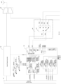
- the radio-frequency system includes a radio-frequency transceiver 100, a first transceiving module 200, a receiving module 300, a first MIMO receiving module 400, a second MIMO receiving module 500, a first antenna Ant1, a second antenna Ant2, a third antenna Ant3, and a fourth antenna Ant4.
- the first antenna Ant1, the second antenna Ant2, the third antenna Ant3, and the fourth antenna Ant4 can be used to support reception and transmission of radio-frequency signals in different frequency bands.
- the radio-frequency signals may include 5G signals, 4G signals, 3G signals, 2G signals, etc.
- the first antenna Ant1, the second antenna Ant2, the third antenna Ant3, and the fourth antenna Ant4 may be formed by any suitable type of antenna.
- the first antenna Ant1, the second antenna Ant2, the third antenna Ant3, and the fourth antenna Ant4 may include an antenna having a resonant element and formed by at least one of the following antenna structures: an array antenna structure, a loop antenna structure, a patch antenna structure, a slot antenna structure, a spiral antenna structure, a strip antenna, a monopole antenna, a dipole antenna, or the like.
- Different types of antennas can be used for different frequency bands and combinations of frequency bands.
- types of the first antenna Ant1, the second antenna Ant2, the third antenna Ant3, and the fourth antenna Ant4 are not further limited.
- the first transceiving module 200 may have at least four receiving paths to support reception of 5G signals in four predetermined frequency bands.
- the first transceiving module 200 may be an integrated device, for example, a built-in low noise Middle and High Band Power Amplifier Modules including Duplexers With LNA (MHB L-PA Mid), i.e., a radio-frequency L-PA Mid device.
- the first transceiving module 200 can also support reception and transmission of middle frequency signals and high frequency signals in a number of frequency bands.
- the receiving module 300 has at least four receiving paths to support reception of 5G signals in four predetermined frequency bands.
- the receiving module 300 may be an integrated device, for example, a Diversity Receive (DRX) module, i.e., a radio-frequency DRX device.
- DRX Diversity Receive
- the receiving module 300 can also support reception of low frequency signals, middle frequency signals, and high frequency signals in a number of frequency bands.
- the four receiving paths of each of the first transceiving module 200 and the receiving module 300 can also implement reception control of 4G LTE signals in a number of middle and high frequency bands, for example, reception control of signals in B1, B3, B7, and B41 frequency bands.
- Some of the 4G LTE signals are in the same frequency bands (e.g., N1, N3, N7, N41) range as 5G NR signals. That is, the first transceiving module 200 can implement reception control of some 5G NR signals.
- a relationship between the 5G NR signals and the 4G LTE signals is shown in Table 2, in which receiving channels of N1, N3, N7, and N41 frequency bands of the 5G NR signals are shared with receiving channels of B1, B3, B7, and B41 frequency bands of the 4G LTE signals in one-to-one correspondence.
- each of the first transceiving module 200 and the receiving module 300 can implement reception control of B1, B3, B7, B41, N1, N3, N7, and N41 frequency bands.
- the B1 and N1 frequency bands share one receiving path, e.g., receiving path B1.
- the B3 and N3 frequency bands share one receiving path, e.g., receiving path B3.
- the B7 and N7 frequency bands share one receiving path, e.g., receiving path B7.
- the B41 and N41 frequency bands share one receiving path, e.g., receiving path B41.
- the radio-frequency transceiver 100 is connected to the first antenna Ant1 via the first transceiving module 200 to form a first MIMO receiving channel for 5G signals.
- the first MIMO receiving channel can support reception of 5G signals in four predetermined frequency bands.
- the radio-frequency transceiver 100 is connected to the second antenna Ant2 via the receiving module 300 to form a second MIMO receiving channel for 5G signals.
- the second MIMO receiving channel can support reception of 5G signals in four predetermined frequency bands.
- the radio-frequency transceiver 100 is connected to the third antenna Ant3 via the first MIMO receiving module 400 to form a third MIMO receiving channel for 5G signals.
- the radio-frequency transceiver 100 is connected to the fourth antenna Ant4 via the second MIMO receiving module 500 to form a fourth MIMO receiving channel for 5G signals.
- Both the first MIMO receiving channel and the second MIMO receiving channel may include four sub-receiving paths, i.e., receiving path B1, receiving path B3, receiving path B7, and receiving path B41.
- the first MIMO receiving module 400 and the second MIMO receiving module 500 have each four receiving paths configured to support the reception of the 5G signals in the four predetermined frequency bands.
- the four receiving paths of each of the first MIMO receiving module 400 and the second MIMO receiving module 500 may be four sub-receiving paths of receiving path N1, receiving path N3, receiving path N7, and receiving path N41, which can be used to support reception of four 5G N1, N3, N7, and N41 frequency bands.
- the first MIMO receiving module 400 and the second MIMO receiving module 500 have each only four receiving paths configured to support the reception of the 5G signals in the four predetermined frequency bands, and thus each receiving path can be utilized, thereby improving use efficiency of the first MIMO receiving module 400 and the second MIMO receiving module 500 as well as lowering the costs.
- a space occupied by devices can be reduced, while a link loss of the receiving paths can be reduced.
- the first MIMO receiving module 400 and the second MIMO receiving module 500 have each an antenna port MHB ANT and four receiving ports LNA OUT (1, 2, 3, 4).
- Each of the first MIMO receiving module 400 and the second MIMO receiving module 500 includes a first switching unit and four filtering units.
- the first MIMO receiving module 400 is taken as an example for description.
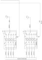
- the first MIMO receiving module 400 includes a first switching unit 410 and four filtering units 420.
- the first switching unit 410 includes a first terminal and four second terminals. The first terminal is connected to the antenna port MHB ANT.
- Each second terminal of the first switching unit 410 is connected to one receiving port LNA OUT via one filtering unit 420 to switch on a receiving path between the antenna port MHB ANT and any one of the receiving ports LNA OUT. That is, the filtering unit 420 is disposed on each receiving path to perform filtering processing on received 5G signals. In addition, frequency bands of 5G signals outputted from the filtering units 420 are different from one another.
- the filtering unit 420 may include a filter, which only allows 5G signals in the predetermined frequency bands to transmit.
- 5G signals in a plurality of frequency bands include four different frequency bands, i.e., N1, N3, N7, and N41 frequency bands
- four filtering units 420 i.e., four filters
- the radio-frequency system can control an on-off state of the first switching unit 410 to transmit the 5G signals in the plurality of frequency bands to any of the filtering units 420.
- the filter may be a band-pass filter, a high-pass filter, or the like. It should be noted that a type of a filter in each filtering unit 420 is not further limited in the embodiments of the present disclosure.
- a suitable filter can be selected based on a frequency band of a 5G signal on which the filtering processing is to be performed.
- the first switching unit 410 is a Single-Pole Four-Throw (SP4T) switch
- the four filtering units 420 may be respectively defined as a first filtering unit 420, a second filtering unit 420, a third filtering unit 420, and a fourth filtering unit 420.
- a contact 1 of the SP4T switch as the first terminal of the first switching unit 410, is connected to the antenna port MHB ANT; and contact 2, contact 3, contact 4, and contact 5 of the SP4T switch may be used as the four second terminals of the first switching unit 410.
- the receiving path N1 is formed by connecting the antenna port MHB ANT to one receiving port LNA OUT1 via the contact 1, the contact 2, and the first filtering unit 420.
- the receiving path N3 is formed by connecting the antenna port MHB ANT to another receiving port LNA OUT2 via the contact 1, the contact 3, and the second filtering unit 420.
- the receiving path N7 is formed by connecting the antenna port MHB ANT to yet another receiving port LNA OUT3 via the contact 1, the contact 2, and the third filtering unit 420.
- the receiving path N41 is formed by connecting the antenna port MHB ANT to still yet another receiving port LNA OUT4 via the contact 1, the contact 2, and the fourth filtering unit 420.
- the first switching unit 410 may also include a plurality of Single Pole Double Throw (SPDT) switches that can be controlled in a time-sharing manner to switch on any of the receiving paths N1, N3, N7, and N41 at the same moment.
- SPDT Single Pole Double Throw
- composition of the first switching unit 410 is not further limited in the embodiments of the present disclosure, and it can be set as desired.
- the first MIMO receiving module 400 and the second MIMO receiving module 500 may have the identical or different structures.
- each of the first MIMO receiving module 400 and the second MIMO receiving module 500 has only four receiving paths, e.g., the receiving path N1, the receiving path N3, the receiving path N7, and the receiving path N41, which are adapted to support the reception of 5G signals in the four N1, N3, N7, and N41 frequency bands.
- the radio-frequency system can support the 4*4 MIMO function of the 5G signals in the plurality of frequency bands.
- each of the first MIMO receiving module 400 and the second MIMO receiving module 500 has the antenna port MHB ANT, a polling transmitting port SRS, and four receiving ports LNA OUT.
- the first switching unit 410 may include a first terminal and five second terminals.
- the first switching unit 410 may be a Single-Pole Five-Throw (SP5T) switch.
- SP5T Single-Pole Five-Throw
- a contact 1 of the SP5T switch as the first terminal of the first switching unit 410, is connected to the antenna port MHB ANT, and contact 2, contact 3, contact 4, contact 5, and contact 6 of the SP4T switch may be used as the four second terminals of the first switching unit 410.
- the receiving path N1 is formed by connecting the antenna port MHB ANT to one receiving port LNA OUT1 via the contact 1, the contact 2, and the first filtering unit 420.
- the receiving path N3 is formed by connecting the antenna port MHB ANT to another receiving port LNA OUT2 via the contact 1, the contact 3, and the second filtering unit 420.
- the receiving path N7 is formed by connecting the antenna port MHB ANT to yet another receiving port LNA OUT3 via the contact 1, the contact 2, and the third filtering unit 420.
- the receiving path N41 is formed by connecting the antenna port MHB ANT to still yet another receiving port LNA OUT4 via the contact 1, the contact 2, and the fourth filtering unit 420.
- the transmitting path is formed by connecting the polling transmitting port SRS to the antenna port MHB ANT via the contact 6 and the contact 1.
- the polling transmitting port SRS may be connected to the first transceiving module 200 according to any of the above embodiments, and the polling transmitting port SRS is configured to receive 5G signals in various frequency bands transmitted by the first transceiving module 200 to transmit the received 5G signals to an antenna connected to the antenna port MHB ANT via the transmitting path, thereby achieving the transmission of the 5G signals.
- each of the first MIMO receiving module 400 and the second MIMO receiving module 500 further includes a second switching unit 430.
- the first MIMO receiving module 400 is taken as an example for description.
- the second switching unit 430 of the first MIMO receiving module 400 includes four first terminals and four second terminals.
- the four first terminals are connected to the four filtering units 420 in one-to-one correspondence.
- the four second terminals are connected to the four receiving ports LNA OUT1, LNA OUT2, LNA OUT3, LNA OUT4 in one-to-one correspondence.
- the second switching unit 430 may be a Four-Pole Four-Throw (4P4T) switch.
- the first MIMO receiving module 400 and the second MIMO receiving module 500 can be flexibly controlled to output 5G signals in at least one of the four N1, N3, N7, and N41 frequency bands to the radio-frequency transceiver 100.
- each of the first MIMO receiving module 400 and the second MIMO receiving module 500 further includes a control unit.
- the first MIMO receiving module 400 is taken as an example for description.
- a control unit 440 of the first MIMO receiving module 400 may be connected to the first switching unit 410 and the second switching unit 430, and the control unit 440 of the first MIMO receiving module 400 may be configured to control the first switching unit 410 and the second switching unit 430 to selectively switch on any of the receiving paths.
- the control unit 440 may be a Mobile Industry Processor Interface (MIPI)-Radio Frequency Front End Control Interface (RFFE) control unit or an RFFE control unit, which conforms to control protocols of an RFFE bus.
- MIPI Mobile Industry Processor Interface
- RFFE Radio Frequency Front End Control Interface
- the first MIMO receiving module 400 and second MIMO receiving module 500 include the MIPI-RFFE control unit as the control unit, the first MIMO receiving module 400 and second MIMO receiving module 500 further have each an input pin CLK for clock signals, an input or bidirectional pin SDATAS for unidirectional/bidirectional data signals, a power pin VDD, a reference voltage pin VIO, etc.
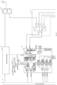
- a 5G NR DRX device may be formed by integrating the first switching unit, four filtering units, second switching unit, and control unit of the first MIMO receiving module 400 or the second MIMO receiving module 500 into the same device. That is, the first MIMO receiving module 400 can be interpreted as a first 5G NR DRX device and the second MIMO receiving module 500 can be interpreted as a second 5G NR DRX device. As an example, the first MIMO receiving module 400 is described below. As illustrated in FIG. 4 , the respective devices in the 5G NR DRX device are integrated and packaged in the same packaged module. As illustrated in FIG.
- the respective pins in the first MIMO receiving module 400 correspond to a plurality of ports in the first MIMO receiving module 400 in one-to-one correspondence.
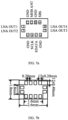
- the first MIMO receiving module 400 has a packaging form illustrated in FIG. 6b .
- the respective devices in the MIMO receiving module 300 are integrated and packaged in the same packaged module.
- the respective pins in the first MIMO receiving module 400 correspond to the plurality of ports in the first MIMO receiving module 400 in one-to-one correspondence.
- the first MIMO receiving module 400 has a packaging form illustrated in FIG. 7b .
- the first MIMO receiving module 400 and the second MIMO receiving module 500 have a high integration level, thereby reducing a space occupied by each device and facilitating the miniaturization of the first MIMO receiving module 400 and the second MIMO receiving module 500. Meanwhile, the costs can be saved, and utilization rate of each device can be improved.
- MIMO operating paths e.g., Channel 0, Channel 1, Channel 2, and Channel 3 for 4*4 MIMO in the N41 frequency band is briefly described below.
- N1, N3, and N7 are similar to that of N41 and will not be described in detail herein.
- the radio-frequency system in any of the above embodiments can support 4*4 MIMO in the four N1, N3, N7, and N41 frequency bands.
- each of the first MIMO receiving module 400 and the second MIMO receiving module 500 has only four receiving paths configured to support the reception of the 5G signals in the four predetermined frequency bands, making each receiving path to be utilized, improving use efficiency of the first MIMO receiving module 400 and the second MIMO receiving module 500, lowering the costs, and decreasing the link loss of the receiving paths.
- the first transceiving module 200 further has a plurality of transmitting channels configured to support transmission of the 5G signals in the plurality of predetermined frequency bands.
- the plurality of transmitting paths and the plurality of receiving paths may be arranged in correspondence.
- the plurality of transmitting paths can implement transmission control of B1, B3, B7, B41, N1, N3, N7, and N41 frequency bands.
- the B1 and N1 frequency bands share one transmitting path, e.g., transmitting path B1.
- the B3 and N3 frequency bands share one transmitting path, e.g., transmitting path B3.
- the B7 and N7 frequency bands share one transmitting path, e.g., transmitting path B7.
- the B41 and N41 frequency bands share one transmitting path, e.g., transmitting path B41.
- the first transceiving module 200 has a multi-channel selection switch to selectively switch to any of the transmitting paths in the first transceiving module 200 or any of the transmitting paths.
- the first transceiving module 200 has two antenna ports ANT1, ANT2.
- the two antenna ports ANT1, ANT2 are configured to transmit 4G/5G signals in different frequency bands.
- 4G/5G signals in the frequency bands B1/N1 and B3/N3 may be transmitted via the antenna port ANT1
- 4G/5G signals in the frequency bands B7/N7 and B41/N41 may be transmitted via the antenna port ANT2.
- the multi-channel selection switch 210 may include two first terminals and a plurality of second terminals.
- the two first terminals of the multi-channel selection switch 210 may be connected to the two antenna ports ANT1 , ANT2 of the first transceiving module 200 in one-to-one correspondence, and the plurality of second terminals of the multi-channel selection switch 210 may be correspondingly connected to the plurality of transmitting paths and the plurality of receiving paths, thereby implementing the reception and transmission control of 4G/5G signals in the plurality of predetermined frequency bands.
- each transmitting path may include a power amplifier (PA), a filter, a radio-frequency switch, and other devices for performing amplification, filtering, and transmission control switching of 4G/5G signals in different frequency bands.
- Each receiving path may include a radio-frequency switch, a filter, a low noise amplifier, etc., for performing amplification, filtering, and reception control switching of 4G/5G signals in different frequency bands received by the antenna port MHB ANT.
- the first transceiving module 200 is further configured to receive and transmit 4G signals in other middle and high frequency bands.
- the first transceiving module 200 may further be configured to implement reception and transmission control of 4G signals in frequency bands such as B25, B30, B32, B66, and B39.
- the receiving module 300 has an antenna port MHB ANT and a transmitting port MHB TRX1.
- the receiving module 300 includes a seventh switching unit 310 and a plurality of receiving circuits.
- the seventh switching unit 310 includes a first terminal and a plurality of second terminals.
- the first terminal of the seventh switching unit 310 is connected to the antenna port MHB ANT.
- a part of the plurality of second terminals of the seventh switching unit 310 are connected to the plurality of receiving circuits in one-to-one correspondence.
- One of the plurality of second terminals other than the part of the plurality of second terminals of the seventh switching unit 310 is connected to the transmitting port MHB TRX1.
- Each receiving circuit may include a radio-frequency switch, a filter, a low noise amplifier, etc., for performing amplification, filtering, and reception control switching of 4G/5G signals in different frequency bands received by the antenna port MHB ANT.
- the seventh switching unit 310 may be a Single-Pole Seven-Throw (SP7T) switch.
- the receiving module 300 is further configured to receive 4G signals in other low, middle, and high frequency bands.
- the receiving module 300 may further be configured to implement reception and transmission control of 4G signals in frequency bands such as B8, B26, B25, B39, B4, B34, B66, and B40.
- the radio-frequency system provides feedback of channel information in two different modes, i.e., Precoding Matrix Indicator (PMI) and Sounding Reference Signal (SRS).
- PMI is a mandatory function for all 5G communication devices
- SRS is an optional function.
- PMI is a mode that the base station estimates channel information and resource requirements in accordance with a pre-determined mechanism based on a measurement of a terminal and various quantization algorithms, and reports the channel information and the resource requirements to the base station.
- SRS is a mode that the terminal directly reports the channel information to the base station by means of channel reciprocity. Obviously, SRS is more accurate than PMI.
- the base station can detect a position of the terminal and a channel quality by transmitting SRS information by means of the communication device. SRS antenna polling transmission is explained in detail below.
- the channel estimation is more accurate, and thus the corresponding rate can be higher.
- the SA mode can complete the channel estimation faster than the NSA mode, thereby increasing a network channel estimation speed.
- the radio-frequency system further includes a switching module 600.
- the switching module 600 is connected to the first transceiving module 200, the receiving module 300, the first MIMO receiving module 400, the second MIMO receiving module 500, the first antenna Ant1 , the second antenna Ant2 , the third antenna Ant3 , and the fourth antenna Ant4 .
- the switching module 600 is configured to switch on a transmitting path between the radio-frequency transceiver 100 and each of the first antenna Ant1 , the second antenna Ant2 , the third antenna Ant 3, and the fourth antenna Ant4 , enabling the radio-frequency system to support a 1T4R SRS function, i.e., enabling the radio-frequency system to support an SRS function in the SA mode.
- the switching module 600 of the corresponding radio-frequency system may include a third switching unit 610, as illustrated in FIG. 11 .
- the third switching unit 610 includes two first terminals and four second terminals.
- the two first terminals of the third switching unit 610 are connected to two antenna ports ANT1, ANT2 of the first transceiving module 200 in one-to-one correspondence; one second terminal of the third switching unit 610 is connected to the first antenna Ant1; another second terminal of the third switching unit 610 is connected to the second antenna Ant2 via the receiving module 300; yet another second terminal of the third switching unit 610 is connected to the polling transmitting port SRS of the first MIMO receiving module 400; the antenna port MHB ANT of the first MIMO receiving module 400 is connected to the third antenna Ant3; still yet another second terminal of the third switching unit 610 is connected to the polling transmitting port SRS of the second MIMO receiving module 500; and the antenna port MHB ANT of the second MIMO receiving module 500 is connected to the fourth antenna Ant4.
- the radio-frequency system can support the 1T4R SRS function.
- the third switching unit 610 may be a Double-Pole Four-Throw (DP4T) switch.
- Contact 1 and contact 2 of the DP4T switch serve as the two first terminals of the third switching unit 610, and contact 3, contact 4, contact 5, and contact 6 of the DP4T switch serve as four second terminals of the third switching unit 610.
- the contact 1 and contact 2 of the DP4T switch are connected to two antenna ports ANT1, ANT2 of the first receiving module 300, respectively.
- the contact 3 of the DP4T switch is connected to the first antenna Ant1.
- the contact 4 of the DP4T switch is connected to the transmitting port MHB TRX1 of the receiving module 300.
- the antenna port MHB ANT of the receiving module 300 is connected to the second antenna Ant2.
- the contact 5 of the DP4T switch is connected to the polling transmitting port SRS of the first MIMO receiving module 400.
- the antenna port MHB ANT of the first MIMO receiving module 400 is connected to the third antenna Ant3.
- the contact 6 of the DP4T switch is connected to the polling transmitting port SRS of the second MIMO receiving module 500.
- the antenna port MHB ANT of the second MIMO receiving module 500 is connected to the fourth antenna Ant4.
- the above-mentioned radio-frequency system can support the 4*4 MIMO function in the N1, N3, N7, and N41 frequency bands as well as the SRS function of the N1, N3, N7, and N41 frequency bands in the SA mode.
- operation principles of paths Channel 0, Channel 1, Channel 2, and Channel 3 of N41 RX MIMO are analyzed below.
- Radio-frequency transceiver 100 ⁇ high frequency transmitting port MHB TRX14G HB RFIN of the first transceiving module 200 ⁇ transmitting path N41 (power amplifier (PA), switch 4P4T#1, filter) ⁇ multi-channel selection switch 210 ⁇ antenna port ANT2 ⁇ path 2 ⁇ third switching unit 610 ⁇ path 3 ⁇ first antenna Ant1, for implementing the SRS function; the third switching unit 610 ⁇ path 4 ⁇ transmitting port MHB TRX1 of the receiving module 300 ⁇ SP7T switch 310 of the receiving module 300 ⁇ antenna port MHB ANT of the receiving module 300 ⁇ path 7 ⁇ second antenna Ant2, for implementing the SRS function; the third switching unit 610 ⁇ path 5 ⁇ polling transmitting port SRS of the first MIMO receiving module 400 ⁇ first switching unit 410 ⁇ antenna port MHB ANT of the first MIMO receiving module 400 ⁇ path 8 ⁇ third antenna Ant3, for implementing the SRS function; the third switching unit 610 ⁇ path 6 ⁇ polling transmitting port SRS of the second MIMO receiving
- Channel 0', Channel 1', Channel 2', and Channel 3' can be interpreted as SRS operating paths.
- the first switching unit 410 in each of the first MIMO receiving module 400 and the second MIMO receiving module 500 is an SP4T switch. That is, based on the first MIMO receiving module 400 and the second MIMO receiving module 500 as illustrated in FIG. 4 , the switching module 600 of the radio-frequency system may include a fourth switching unit 620, a fifth switching unit 630, and a sixth switching unit 640.
- the fourth switching unit 620 includes two firs terminals and four second terminals. The two first terminals of the fourth switching unit 620 are connected to the two antenna ports ANT1, ANT2 of the first transceiving module 200 in one-to-one correspondence. One second terminal of the fourth switching unit 620 is connected to the first antenna Ant1 .
- Another second terminal of the fourth switching unit 620 is connected to the second antenna Ant2 via the receiving module 300. Yet another second terminal of the fourth switching unit 620 is connected to the third antenna Ant3 via the fifth switching unit 630. Still yet another second terminal of the fourth switching unit 620 is connected to the fourth antenna Ant4 via the sixth switching unit 640.
- the fifth switching unit 630 is also disposed on the fourth MIMO receiving channel and connected to the first MIMO receiving module 400.
- the sixth switching unit 640 is also disposed on the fourth MIMO receiving channel and connected to the second MIMO receiving module 500.
- the fourth switching unit 620 may be a DP4T switch, and the fifth switching unit 630 and the sixth switching unit 640 are both SPDT switches.
- a contact 1 and a contact 2 of the DP4T switch serve as the two first terminals of the fourth switching unit 620, and a contact 3, a contact 4, a contact 5, and a contact 6 of the DP4T switch serve as the four second terminals of the fourth switching unit 620.
- the contact 1 and contact 2 of the DP4T switch are connected to the two antenna ports ANT1, ANT2 of the first receiving module 300 in one-to-one correspondence.
- the contact 3 of the DP4T switch is connected to the first antenna Ant1.
- the contact 4 of the DP4T switch is connected to the transmitting port MHB TRX1 of the receiving module 300.
- the antenna port MHB ANT of the receiving module 300 is connected to the second antenna Ant2.
- the contact 5 of the DP4T switch is connected to a contact 2 of the SPDT switch #1.
- a contact 3 of the SPDT switch #1 is connected to the antenna port MHB ANT of the first MIMO receiving module 400.
- a contact 1 of the SPDT switch #1 is connected to the third antenna Ant3.
- the contact 6 of the DP4T switch is connected to a contact 2 of the SPDT switch #2.
- a contact 3 of the SPDT switch #2 is connected to the antenna port MHB ANT of the second MIMO receiving module 500.
- a contact 1 of the SPDT switch #2 is connected to the fourth antenna Ant4.
- the above radio-frequency system can support both the 4*4 MIMO function in the N1, N3, N7, and N41 frequency bands and the SRS function of the N1, N3, N7, and N41 frequency bands in the SA mode.
- operation principles of paths Channel 0, Channel 1, Channel 2, and Channel 3 of N41 RX MIMO are analyzed below.
- Radio-frequency transceiver 100 ⁇ high frequency transmitting port MHB TRX14G HB RFIN of the first transceiving module 200 ⁇ transmitting path N41 (power amplifier (PA), switch 4P4T#1, filter) ⁇ multi-channel selection switch 210 ⁇ antenna port MHB ANTANT2 ⁇ path 2 ⁇ fourth switching unit 620 ⁇ path 3 ⁇ first antenna Ant1, for implementing the SRS function; the fourth switching unit 620 ⁇ path 4 ⁇ transmitting port MHB TRX1 of the receiving module 300 ⁇ SP7T switch 310 of the receiving module 300 ⁇ antenna port MHB ANT of the receiving module 300 ⁇ path 7 ⁇ second antenna Ant2 , for implementing the SRS function; the fourth switching unit 620 ⁇ path 5 ⁇ SPDT switch # 1 ⁇ path 8 ⁇ third antenna Ant3, for implementing the SRS function; the fourth switching unit 620 ⁇ path 6 ⁇ SPDT switch #2 ⁇ fourth antenna Ant4 , for implementing the SRS function.
- path N41 power amplifier (PA), switch 4P4T#1, filter
- Channel 0', Channel 1', Channel 2', and Channel 3' can be interpreted as SRS operating paths.
- the radio-frequency system when the first transceiving module 200 in the embodiments of the present disclosure is an MHB L-PA Mid device supporting only the SA mode, the radio-frequency system also only supports the SRS function in the SA mode, correspondingly.
- the radio-frequency system can also support the SRS function in both the NSA mode and the SA mode, correspondingly.
- the radio-frequency systems illustrated in FIG. 11 and FIG. 12 can support the 4*4 MIMO function in the N1, N3, N7, and N41 frequency bands as well as the SRS function of the N1, N3, N7, and N41 frequency bands in the SA mode.
- the radio-frequency system illustrated in FIG. 11 by providing the polling transmitting port SRS in the first MIMO receiving module 400 and the second MIMO receiving module 500, the number of switches in the switching module 600 can be reduced.
- the fifth switching unit 630 and the sixth switching unit 640 illustrated in FIG. 12 can be omitted.
- the radio-frequency system illustrated in FIG. 11 has a simpler structure.
- wiring complexity of the radio-frequency system is simplified, and an occupied area is small, thereby facilitating the miniaturization of the radio-frequency system and lowering the costs thereof.
- the radio-frequency system in any of the above embodiments may further include a second transceiving module 700, a first combiner 800, and a second combiner 900.
- the first combiner 800 is connected to the second transceiving module 700, the switching module 600, and the second antenna Ant2.
- the second combiner 900 is connected to the receiving module 300 and the third antenna Ant3.
- the second transceiving module 700 is connected to the first transceiving module 200 and configured to support reception and transmission of radio-frequency signals in a plurality of low frequency bands.
- the first transceiving module 200 may be configured to support reception and transmission control of 4G signals in low frequency bands.
- the first transceiving module 200 may be a built-in low noise Low Band Power Amplifier Modules including Duplexers With LNA (LB L-PA Mid), which can be interpreted as a packaged chip integrating transmitting and receiving channels for a plurality of frequency bands, including B8, B12, B20, B26, 2G LB, and 2G HB GSM.
- the radio-frequency system can support the SRS function of the N3, N7, and N41 frequency bands in the SA mode, and it can also implement reception and transmission control of signals in B8, B12, B20, B26, 2G LB, and 2G HB GSM through the first transceiving module 200 and the first antenna Ant1, thereby expanding communication frequency bands of the radio-frequency system and improving communication performance of the radio-frequency system.
- a communication device is further provided.
- the communication device has the radio-frequency system according to any of the above embodiments that can support the 4*4 MIMO function in the N1, N3, N7, and N41 frequency bands as well as the SRS function of the N1, N3, N7, and N41 frequency bands in the SA mode.
- each of the first MIMO receiving module 400 and the second MIMO receiving module 500 has only four receiving paths for supporting the reception of the 5G signals in the four predetermined frequency bands, and thus each receiving path can be utilized. In this way, the use efficiency of the first MIMO receiving module 400 and the second MIMO receiving module 500 can be improved, the costs can be lowered, and a link loss of the receiving paths can be reduced.
Landscapes
- Engineering & Computer Science (AREA)
- Computer Networks & Wireless Communication (AREA)
- Signal Processing (AREA)
- Transceivers (AREA)
- Mobile Radio Communication Systems (AREA)
Abstract
Description
- The present application claims a priority to
Chinese Patent Application No. 202011032759X, entitled "RADIO-FREQUENCY SYSTEM AND COMMUNICATION DEVICE", and filed with China National Intellectual Property Administration on September 27, 2020 - The present disclosure relates to the field of radio-frequency technologies, and more particularly, to a radio-frequency system and a communication device.
- The statements herein provide only background information relevant to the present disclosure and do not necessarily constitute exemplary related art.
- With the development and advancement of technology, a high integration level and miniaturization of devices have become a development trend to cope with the increasing demands of various network standards and to solve a problem of a space strain on a Printed Circuit Board (PCB) layout. From initial Phase2 products that only support a single frequency band to Phase7 products that support integration of various standards, the integration level of devices becomes increasingly higher, while a package size of devices also becomes increasingly smaller. For example, the Phase7 product, in which a diversity reception device for supporting middle and high frequency bands of Long-Term Evolution (LTE) signals is applied to a radio-frequency transceiving system to support a Multiple Input Multiple Output (MIMO) function of a 5-th Generation (5G) mobile communication technology New Radio (NR) signal, requires high costs and occupies a large space.
- According to embodiments of the present disclosure, a radio-frequency system and a communication device are provided.
- A radio-frequency system includes a radio-frequency transceiver, a first transceiving module, a receiving module, a first Multiple Input Multiple Output (MIMO) receiving module, a second MIMO receiving module, a first antenna, a second antenna, a third antenna, and a fourth antenna. The radio-frequency transceiver is connected to the first antenna via the first transceiving module to form a first MIMO receiving channel for 5-th Generation mobile communication technology (5G) signals. The radio-frequency transceiver is connected to the second antenna via the receiving module to form a second MIMO receiving channel for 5G signals. Each of the first transceiving module and the receiving module has at least four receiving paths configured to support reception of 5G signals in four predetermined frequency bands. The radio-frequency transceiver is connected to the third antenna via the first MIMO receiving module to form a third MIMO receiving channel for 5G signals. The radio-frequency transceiver is connected to the fourth antenna via the second MIMO receiving module to form a fourth MIMO receiving channel for 5G signals. Each of the first MIMO receiving module and the second MIMO receiving module has four receiving paths configured to support the reception of 5G signals in the four predetermined frequency bands.
- A communication device includes the radio-frequency system as described above.
- In the above-mentioned radio-frequency system and communication device, four MIMO receiving channels can be formed by means of the first transceiving module, the receiving module, the first MIMO receiving module, the second MIMO receiving module, and the four antennas, and the four MIMO receiving channels enable the radio-frequency system to support a 4*4 MIMO function of 5G signals in the four predetermined frequency bands, thereby satisfying the communication needs inland and abroad. In addition, each of the first MIMO receiving module and the second MIMO receiving module has only four receiving paths to support the reception of 5G signals in the four predetermined frequency bands to utilize each receiving path, thereby improving use efficiency of the first MIMO receiving module and the second MIMO receiving module and reducing the costs. Meanwhile, compared with a diversity reception device supporting middle and high frequency bands of LTE signals, a space occupied by devices can be reduced, and a link loss of the receiving paths can be also reduced.
- One or more of the embodiments of the present disclosure are described in detail below in combination with the accompanying drawings. Other features, objects and advantages of the present disclosure will become apparent from the specification, the accompanying drawings, and the claims as attached.
- In order to clearly explain technical solutions of embodiments of the present disclosure or in the related art, drawings used in description of the embodiments or the related art will be briefly described below. The drawings described below merely illustrate some embodiments of the present disclosure. Based on these drawings, other drawings can be obtained by those skilled in the art without creative effort.
-
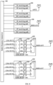
FIG. 1 is a first schematic diagram of a framework of a radio-frequency system according to an embodiment. -
FIG. 2 is a first schematic diagram of a first MIMO receiving module according to an embodiment. -
FIG. 3 is a second schematic diagram of a first MIMO receiving module according to an embodiment. -
FIG. 4 is a third schematic diagram of a first MIMO receiving module according to an embodiment. -
FIG. 5 is a fourth schematic diagram of a first MIMO receiving module according to an embodiment. -
FIG. 6a is a schematic diagram of pins of a first MIMO receiving module ofFIG. 4 . -
FIG. 6b is a schematic diagram of a package structure of a first MIMO receiving module ofFIG. 4 . -
FIG. 7a is a schematic diagram of pins of a first MIMO receiving module ofFIG. 5 . -
FIG. 7b is a schematic diagram of a package structure of a first MIMO receiving module ofFIG. 5 . -
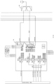
FIG. 8 is a second schematic diagram of an architecture of a radio-frequency system according to an embodiment. -
FIG. 9 is a schematic diagram of a framework of a first transceiving module according to an embodiment. -
FIG. 10 is a schematic diagram of a framework of a receiving module according to an embodiment. -
FIG. 11 is a third schematic diagram of a framework of a radio-frequency system according to an embodiment. -
FIG. 12 is a fourth schematic diagram of a framework of a radio-frequency system according to an embodiment. -
FIG. 13 is a fifth schematic diagram of a framework of a radio-frequency system according to an embodiment. -
FIG. 14 is a sixth schematic diagram of a framework of a radio-frequency system according to an embodiment. - In order to make objects, technical solutions, and advantages of the present disclosure more apparent, the present disclosure will be described in detail below with reference to the accompanying drawings and embodiments. It should be understood that the embodiments described herein are only used to explain, rather than limiting, the present disclosure.
- It should be understood that terms "first", "second", etc., used in the present disclosure may be used herein to describe various elements, but these elements are not limited by these terms. These terms are used only to distinguish one element from another element. For example, without departing from the scope of the present disclosure, a first transceiving module may be referred to as a second transceiving module, and similarly, the second transceiving module may be referred to as the first transceiving module. The first transceiving module and the second transceiving module are different transceiving modules.
- In addition, the term "first" or "second" is only for descriptive purposes, rather than indicating or implying relative importance or implicitly indicating the number of indicated technical features. Therefore, the features defined with "first" or "second" can explicitly or implicitly include at least one of the features. In the description of the present disclosure, "plurality of' means at least two, unless otherwise specifically indicated. In the present disclosure, "a number of" means at least one, unless otherwise specifically indicated.
- A radio-frequency transceiving system involved in the embodiments of the present disclosure can be applied to a communication device having wireless communication capabilities. The communication device may be a handheld apparatus, a vehicle-mounted apparatus, a wearable apparatus, a computing apparatus, any other processing apparatuses connected to a wireless modem, a user equipment (UE) in various forms (e.g., a mobile phone), or a mobile station (MS), etc. For ease of description, the above-mentioned apparatuses can be collectively referred to as the communication device. A network device may include a base station, an access point, etc.
- As illustrated in
FIG. 1 , an embodiment of the present disclosure provides a radio-frequency system. The radio-frequency system can support a 4*4 MIMO function. The MIMO function refers to using a plurality of transmitting antennas at a transmitting port and a plurality of receiving antennas at a receiving port, to sufficiently use space resources, and realizing multiple transmission and multiple reception through the plurality of antennas. In this way, a channel capacity of the system can be manifold increased without increasing spectrum resources and transmitting power of antennas. The communication device and a base station can constitute 2*2 MIMO or 4*4 MIMO. Taking 4*4 MIMO as an example, configurations for antenna ports of receiving paths are shown in Table 1. It should be noted that when receiving performance is tested with protocols stipulated by China Telecommunication Technology Labs (CTTL), all 4 receiving channels are also connected to a radio-frequency transceiver. The 4 receiving channels form a downlink of MIMO and all receive signals from an uplink base station, improving performance of the radio-frequency system.[Table 1] Configurations for receiving antenna ports Channel Channel 0 Channel 1Channel 2Channel 3Antenna port PRX DRX PRX MIMO DRX MIMO - In Table 1, Channel 0,
Channel 1,Channel 2, andChannel 3 can be interpreted as a first MIMO receiving channel, a second MIMO receiving channel, a third MIMO receiving channel, and a fourth MIMO receiving channel, respectively; the antenna port PRX (main receiving port) can be interpreted as an antenna port of a first transceiving module; the antenna port DRX (diversity receiving port) can be interpreted as an antenna port of a receiving module; the antenna port PRX MIMO (main MIMO receiving port) can be interpreted as an antenna port of the first MIMO receiving module; and the antenna port DRX MIMO (diversity MIMO receiving port) can be interpreted as an antenna port of the second MIMO receiving module. - At present, the China Mobile mainly adopts a N41 5G frequency band, and thus all communication devices support MIMO in the N41 frequency band. The radio-frequency system according to the embodiments of the present disclosure can support 4*4 MIMO in N1, N3, and N7 frequency bands applied by foreign operators, in addition to MIMO in the N41 frequency band.
- In an embodiment, the radio-frequency system includes a radio-
frequency transceiver 100, afirst transceiving module 200, a receivingmodule 300, a firstMIMO receiving module 400, a secondMIMO receiving module 500, a first antenna Ant1, a second antenna Ant2, a third antenna Ant3, and a fourth antenna Ant4. - The first antenna Ant1, the second antenna Ant2, the third antenna Ant3, and the fourth antenna Ant4 can be used to support reception and transmission of radio-frequency signals in different frequency bands. The radio-frequency signals may include 5G signals, 4G signals, 3G signals, 2G signals, etc. The first antenna Ant1, the second antenna Ant2, the third antenna Ant3, and the fourth antenna Ant4 may be formed by any suitable type of antenna. For example, the first antenna Ant1, the second antenna Ant2, the third antenna Ant3, and the fourth antenna Ant4 may include an antenna having a resonant element and formed by at least one of the following antenna structures: an array antenna structure, a loop antenna structure, a patch antenna structure, a slot antenna structure, a spiral antenna structure, a strip antenna, a monopole antenna, a dipole antenna, or the like. Different types of antennas can be used for different frequency bands and combinations of frequency bands. In the embodiments of the present disclosure, types of the first antenna Ant1, the second antenna Ant2, the third antenna Ant3, and the fourth antenna Ant4 are not further limited.
- The
first transceiving module 200 may have at least four receiving paths to support reception of 5G signals in four predetermined frequency bands. In an embodiment, thefirst transceiving module 200 may be an integrated device, for example, a built-in low noise Middle and High Band Power Amplifier Modules including Duplexers With LNA (MHB L-PA Mid), i.e., a radio-frequency L-PA Mid device. Thefirst transceiving module 200 can also support reception and transmission of middle frequency signals and high frequency signals in a number of frequency bands. - The receiving
module 300 has at least four receiving paths to support reception of 5G signals in four predetermined frequency bands. In an embodiment, the receivingmodule 300 may be an integrated device, for example, a Diversity Receive (DRX) module, i.e., a radio-frequency DRX device. The receivingmodule 300 can also support reception of low frequency signals, middle frequency signals, and high frequency signals in a number of frequency bands. - The four receiving paths of each of the
first transceiving module 200 and the receivingmodule 300 can also implement reception control of 4G LTE signals in a number of middle and high frequency bands, for example, reception control of signals in B1, B3, B7, and B41 frequency bands. Some of the 4G LTE signals are in the same frequency bands (e.g., N1, N3, N7, N41) range as 5G NR signals. That is, thefirst transceiving module 200 can implement reception control of some 5G NR signals. A relationship between the 5G NR signals and the 4G LTE signals is shown in Table 2, in which receiving channels of N1, N3, N7, and N41 frequency bands of the 5G NR signals are shared with receiving channels of B1, B3, B7, and B41 frequency bands of the 4G LTE signals in one-to-one correspondence.[Table 2] Basic information of 4G LTE and 5G NR 4G LTE signals 5G NR signals Frequency band Frequency (MHz) Maximum bandwidth (MHz) Frequency band Frequency (MHz) Maximum bandwidth (MHz) B1 1,920∼1,980 20 N1 1,920∼1,980 20 MHz B3 1,710∼1,785 20 N3 1,710∼1,785 20 MHz B7 2,500∼2,570 20 N7 2,500~2,570 20 MHz B41 2,496∼2,690 20 N41 2,496∼2,690 100 MHz - It should be understood that the four receiving paths of each of the
first transceiving module 200 and the receivingmodule 300 can implement reception control of B1, B3, B7, B41, N1, N3, N7, and N41 frequency bands. The B1 and N1 frequency bands share one receiving path, e.g., receiving path B1. The B3 and N3 frequency bands share one receiving path, e.g., receiving path B3. The B7 and N7 frequency bands share one receiving path, e.g., receiving path B7. The B41 and N41 frequency bands share one receiving path, e.g., receiving path B41. - The radio-
frequency transceiver 100 is connected to the first antenna Ant1 via thefirst transceiving module 200 to form a first MIMO receiving channel for 5G signals. The first MIMO receiving channel can support reception of 5G signals in four predetermined frequency bands. The radio-frequency transceiver 100 is connected to the second antenna Ant2 via thereceiving module 300 to form a second MIMO receiving channel for 5G signals. The second MIMO receiving channel can support reception of 5G signals in four predetermined frequency bands. The radio-frequency transceiver 100 is connected to the third antenna Ant3 via the firstMIMO receiving module 400 to form a third MIMO receiving channel for 5G signals. The radio-frequency transceiver 100 is connected to the fourth antenna Ant4 via the secondMIMO receiving module 500 to form a fourth MIMO receiving channel for 5G signals. Both the first MIMO receiving channel and the second MIMO receiving channel may include four sub-receiving paths, i.e., receiving path B1, receiving path B3, receiving path B7, and receiving path B41. - The first
MIMO receiving module 400 and the secondMIMO receiving module 500 have each four receiving paths configured to support the reception of the 5G signals in the four predetermined frequency bands. For example, the four receiving paths of each of the firstMIMO receiving module 400 and the secondMIMO receiving module 500 may be four sub-receiving paths of receiving path N1, receiving path N3, receiving path N7, and receiving path N41, which can be used to support reception of four 5G N1, N3, N7, and N41 frequency bands. - In the above-mentioned radio-frequency system, four MIMO receiving channels can be formed by the
first transceiving module 200, the receivingmodule 300, the firstMIMO receiving module 400, the secondMIMO receiving module 500, and the four antennas, to enable the radio-frequency system to support a 4*4 MIMO function of 5G signals in the four predetermined frequency bands, thereby satisfying communication needs at inland and abroad. Meanwhile, the firstMIMO receiving module 400 and the secondMIMO receiving module 500 have each only four receiving paths configured to support the reception of the 5G signals in the four predetermined frequency bands, and thus each receiving path can be utilized, thereby improving use efficiency of the firstMIMO receiving module 400 and the secondMIMO receiving module 500 as well as lowering the costs. In addition, compared with a diversity reception device supporting middle and high frequency bands of LTE signals, a space occupied by devices can be reduced, while a link loss of the receiving paths can be reduced. - In an embodiment, the first
MIMO receiving module 400 and the secondMIMO receiving module 500 have each an antenna port MHB ANT and four receiving ports LNA OUT (1, 2, 3, 4). Each of the firstMIMO receiving module 400 and the secondMIMO receiving module 500 includes a first switching unit and four filtering units. As illustrated inFIG. 2 , the firstMIMO receiving module 400 is taken as an example for description. The firstMIMO receiving module 400 includes afirst switching unit 410 and four filteringunits 420. Thefirst switching unit 410 includes a first terminal and four second terminals. The first terminal is connected to the antenna port MHB ANT. Each second terminal of thefirst switching unit 410 is connected to one receiving port LNA OUT via onefiltering unit 420 to switch on a receiving path between the antenna port MHB ANT and any one of the receiving ports LNA OUT. That is, thefiltering unit 420 is disposed on each receiving path to perform filtering processing on received 5G signals. In addition, frequency bands of 5G signals outputted from thefiltering units 420 are different from one another. - In an embodiment, the
filtering unit 420 may include a filter, which only allows 5G signals in the predetermined frequency bands to transmit. When 5G signals in a plurality of frequency bands include four different frequency bands, i.e., N1, N3, N7, and N41 frequency bands, four filtering units 420 (i.e., four filters) may be provided correspondingly to implement the filtering processing on the four 5G signals. The radio-frequency system can control an on-off state of thefirst switching unit 410 to transmit the 5G signals in the plurality of frequency bands to any of thefiltering units 420. As an example, the filter may be a band-pass filter, a high-pass filter, or the like. It should be noted that a type of a filter in eachfiltering unit 420 is not further limited in the embodiments of the present disclosure. A suitable filter can be selected based on a frequency band of a 5G signal on which the filtering processing is to be performed. - In an embodiment, the
first switching unit 410 is a Single-Pole Four-Throw (SP4T) switch, and the four filteringunits 420 may be respectively defined as afirst filtering unit 420, asecond filtering unit 420, athird filtering unit 420, and afourth filtering unit 420. As an example, acontact 1 of the SP4T switch, as the first terminal of thefirst switching unit 410, is connected to the antenna port MHB ANT; andcontact 2,contact 3,contact 4, andcontact 5 of the SP4T switch may be used as the four second terminals of thefirst switching unit 410. The receiving path N1 is formed by connecting the antenna port MHB ANT to one receiving port LNA OUT1 via thecontact 1, thecontact 2, and thefirst filtering unit 420. The receiving path N3 is formed by connecting the antenna port MHB ANT to another receiving port LNA OUT2 via thecontact 1, thecontact 3, and thesecond filtering unit 420. The receiving path N7 is formed by connecting the antenna port MHB ANT to yet another receiving port LNA OUT3 via thecontact 1, thecontact 2, and thethird filtering unit 420. The receiving path N41 is formed by connecting the antenna port MHB ANT to still yet another receiving port LNA OUT4 via thecontact 1, thecontact 2, and thefourth filtering unit 420. - Optionally, the
first switching unit 410 may also include a plurality of Single Pole Double Throw (SPDT) switches that can be controlled in a time-sharing manner to switch on any of the receiving paths N1, N3, N7, and N41 at the same moment. - It should be noted that, a specific form of composition of the
first switching unit 410 is not further limited in the embodiments of the present disclosure, and it can be set as desired. In addition, the firstMIMO receiving module 400 and the secondMIMO receiving module 500 may have the identical or different structures. - In an embodiment, each of the first
MIMO receiving module 400 and the secondMIMO receiving module 500 has only four receiving paths, e.g., the receiving path N1, the receiving path N3, the receiving path N7, and the receiving path N41, which are adapted to support the reception of 5G signals in the four N1, N3, N7, and N41 frequency bands. In this way, the radio-frequency system can support the 4*4 MIMO function of the 5G signals in the plurality of frequency bands. - In an embodiment, each of the first
MIMO receiving module 400 and the secondMIMO receiving module 500 has the antenna port MHB ANT, a polling transmitting port SRS, and four receiving ports LNA OUT. As illustrated inFIG. 3 , the firstMIMO receiving module 400 is taken as an example for description. Thefirst switching unit 410 may include a first terminal and five second terminals. In an embodiment, thefirst switching unit 410 may be a Single-Pole Five-Throw (SP5T) switch. As an example, acontact 1 of the SP5T switch, as the first terminal of thefirst switching unit 410, is connected to the antenna port MHB ANT, andcontact 2,contact 3,contact 4,contact 5, andcontact 6 of the SP4T switch may be used as the four second terminals of thefirst switching unit 410. The receiving path N1 is formed by connecting the antenna port MHB ANT to one receiving port LNA OUT1 via thecontact 1, thecontact 2, and thefirst filtering unit 420. The receiving path N3 is formed by connecting the antenna port MHB ANT to another receiving port LNA OUT2 via thecontact 1, thecontact 3, and thesecond filtering unit 420. The receiving path N7 is formed by connecting the antenna port MHB ANT to yet another receiving port LNA OUT3 via thecontact 1, thecontact 2, and thethird filtering unit 420. The receiving path N41 is formed by connecting the antenna port MHB ANT to still yet another receiving port LNA OUT4 via thecontact 1, thecontact 2, and thefourth filtering unit 420. The transmitting path is formed by connecting the polling transmitting port SRS to the antenna port MHB ANT via thecontact 6 and thecontact 1. The polling transmitting port SRS may be connected to thefirst transceiving module 200 according to any of the above embodiments, and the polling transmitting port SRS is configured to receive 5G signals in various frequency bands transmitted by thefirst transceiving module 200 to transmit the received 5G signals to an antenna connected to the antenna port MHB ANT via the transmitting path, thereby achieving the transmission of the 5G signals. - In an embodiment, each of the first
MIMO receiving module 400 and the secondMIMO receiving module 500 further includes asecond switching unit 430. As illustrated inFIG. 4 andFIG. 5 , the firstMIMO receiving module 400 is taken as an example for description. Thesecond switching unit 430 of the firstMIMO receiving module 400 includes four first terminals and four second terminals. The four first terminals are connected to the four filteringunits 420 in one-to-one correspondence. The four second terminals are connected to the four receiving ports LNA OUT1, LNA OUT2, LNA OUT3, LNA OUT4 in one-to-one correspondence. For example, thesecond switching unit 430 may be a Four-Pole Four-Throw (4P4T) switch. By controlling the 4P4T switch, the firstMIMO receiving module 400 and the secondMIMO receiving module 500 can be flexibly controlled to output 5G signals in at least one of the four N1, N3, N7, and N41 frequency bands to the radio-frequency transceiver 100. - In an embodiment, each of the first
MIMO receiving module 400 and the secondMIMO receiving module 500 further includes a control unit. As illustrated inFIG. 4 andFIG. 5 , the firstMIMO receiving module 400 is taken as an example for description. Acontrol unit 440 of the firstMIMO receiving module 400 may be connected to thefirst switching unit 410 and thesecond switching unit 430, and thecontrol unit 440 of the firstMIMO receiving module 400 may be configured to control thefirst switching unit 410 and thesecond switching unit 430 to selectively switch on any of the receiving paths. As an example, thecontrol unit 440 may be a Mobile Industry Processor Interface (MIPI)-Radio Frequency Front End Control Interface (RFFE) control unit or an RFFE control unit, which conforms to control protocols of an RFFE bus. When the firstMIMO receiving module 400 and secondMIMO receiving module 500 include the MIPI-RFFE control unit as the control unit, the firstMIMO receiving module 400 and secondMIMO receiving module 500 further have each an input pin CLK for clock signals, an input or bidirectional pin SDATAS for unidirectional/bidirectional data signals, a power pin VDD, a reference voltage pin VIO, etc. - In an embodiment, a 5G NR DRX device may be formed by integrating the first switching unit, four filtering units, second switching unit, and control unit of the first
MIMO receiving module 400 or the secondMIMO receiving module 500 into the same device. That is, the firstMIMO receiving module 400 can be interpreted as a first 5G NR DRX device and the secondMIMO receiving module 500 can be interpreted as a second 5G NR DRX device. As an example, the firstMIMO receiving module 400 is described below. As illustrated inFIG. 4 , the respective devices in the 5G NR DRX device are integrated and packaged in the same packaged module. As illustrated inFIG. 6a , the respective pins in the first MIMO receiving module 400 (packaged chip) correspond to a plurality of ports in the firstMIMO receiving module 400 in one-to-one correspondence. Through packaging and integration, the firstMIMO receiving module 400 has a packaging form illustrated inFIG. 6b . Correspondingly, as illustrated inFIG. 5 , the respective devices in theMIMO receiving module 300 are integrated and packaged in the same packaged module. As illustrated inFIG. 7a , the respective pins in the first MIMO receiving module 400 (packaged chip) correspond to the plurality of ports in the firstMIMO receiving module 400 in one-to-one correspondence. Through packaging and integration, the firstMIMO receiving module 400 has a packaging form illustrated inFIG. 7b . - The first
MIMO receiving module 400 and the secondMIMO receiving module 500 according to the embodiments of the present disclosure have a high integration level, thereby reducing a space occupied by each device and facilitating the miniaturization of the firstMIMO receiving module 400 and the secondMIMO receiving module 500. Meanwhile, the costs can be saved, and utilization rate of each device can be improved. - Based on the radio-frequency system illustrated in
FIG. 8 , the reception control of MIMO operating paths (e.g., Channel 0,Channel 1,Channel 2, and Channel 3) for 4*4 MIMO in the N41 frequency band is briefly described below. - Path Channel 0: first antenna Ant1→antenna port ANT2 of the
first transceiving module 200→receiving path N41→radio-frequency transceiver 100. - Path Channel 1: second antenna Ant2→antenna port MHB ANT of the receiving
module 300→receiving path N41→radio-frequency transceiver 100. - Path Channel 2: third antenna Ant3→antenna port MHB ANT of the first
MIMO receiving module 400→first switching unit 410→filteringunit 420→second switching unit 430 →radio-frequency transceiver 100. - Path Channel 3: fourth antenna Ant4→antenna port MHB ANT of the second
MIMO receiving module 500→first switching unit 510→filteringunit 520→second switching unit 530→radio-frequency transceiver 100. - MIMO operation principles of N1, N3, and N7 are similar to that of N41 and will not be described in detail herein.
- The radio-frequency system in any of the above embodiments can support 4*4 MIMO in the four N1, N3, N7, and N41 frequency bands. Also, each of the first
MIMO receiving module 400 and the secondMIMO receiving module 500 has only four receiving paths configured to support the reception of the 5G signals in the four predetermined frequency bands, making each receiving path to be utilized, improving use efficiency of the firstMIMO receiving module 400 and the secondMIMO receiving module 500, lowering the costs, and decreasing the link loss of the receiving paths. - As illustrated in
FIG. 9 , in an embodiment, thefirst transceiving module 200 further has a plurality of transmitting channels configured to support transmission of the 5G signals in the plurality of predetermined frequency bands. The plurality of transmitting paths and the plurality of receiving paths may be arranged in correspondence. As an example, the plurality of transmitting paths can implement transmission control of B1, B3, B7, B41, N1, N3, N7, and N41 frequency bands. The B1 and N1 frequency bands share one transmitting path, e.g., transmitting path B1. The B3 and N3 frequency bands share one transmitting path, e.g., transmitting path B3. The B7 and N7 frequency bands share one transmitting path, e.g., transmitting path B7. The B41 and N41 frequency bands share one transmitting path, e.g., transmitting path B41. In an embodiment, thefirst transceiving module 200 has a multi-channel selection switch to selectively switch to any of the transmitting paths in thefirst transceiving module 200 or any of the transmitting paths. - In an embodiment, the
first transceiving module 200 has two antenna ports ANT1, ANT2. The two antenna ports ANT1, ANT2 are configured to transmit 4G/5G signals in different frequency bands. For example, 4G/5G signals in the frequency bands B1/N1 and B3/N3 may be transmitted via the antenna port ANT1, and 4G/5G signals in the frequency bands B7/N7 and B41/N41 may be transmitted via the antenna port ANT2. Themulti-channel selection switch 210 may include two first terminals and a plurality of second terminals. The two first terminals of themulti-channel selection switch 210 may be connected to the two antenna ports ANT1, ANT2 of thefirst transceiving module 200 in one-to-one correspondence, and the plurality of second terminals of themulti-channel selection switch 210 may be correspondingly connected to the plurality of transmitting paths and the plurality of receiving paths, thereby implementing the reception and transmission control of 4G/5G signals in the plurality of predetermined frequency bands. - In an embodiment, each transmitting path may include a power amplifier (PA), a filter, a radio-frequency switch, and other devices for performing amplification, filtering, and transmission control switching of 4G/5G signals in different frequency bands. Each receiving path may include a radio-frequency switch, a filter, a low noise amplifier, etc., for performing amplification, filtering, and reception control switching of 4G/5G signals in different frequency bands received by the antenna port MHB ANT.
- In an embodiment, the
first transceiving module 200 is further configured to receive and transmit 4G signals in other middle and high frequency bands. As an example, thefirst transceiving module 200 may further be configured to implement reception and transmission control of 4G signals in frequency bands such as B25, B30, B32, B66, and B39. - As illustrated in
FIG. 10 , in an embodiment, the receivingmodule 300 has an antenna port MHB ANT and a transmitting port MHB TRX1. The receivingmodule 300 includes aseventh switching unit 310 and a plurality of receiving circuits. Theseventh switching unit 310 includes a first terminal and a plurality of second terminals. The first terminal of theseventh switching unit 310 is connected to the antenna port MHB ANT. A part of the plurality of second terminals of theseventh switching unit 310 are connected to the plurality of receiving circuits in one-to-one correspondence. One of the plurality of second terminals other than the part of the plurality of second terminals of theseventh switching unit 310 is connected to the transmitting port MHB TRX1. Each receiving circuit may include a radio-frequency switch, a filter, a low noise amplifier, etc., for performing amplification, filtering, and reception control switching of 4G/5G signals in different frequency bands received by the antenna port MHB ANT. Theseventh switching unit 310 may be a Single-Pole Seven-Throw (SP7T) switch. - In an embodiment, the receiving
module 300 is further configured to receive 4G signals in other low, middle, and high frequency bands. As an example, the receivingmodule 300 may further be configured to implement reception and transmission control of 4G signals in frequency bands such as B8, B26, B25, B39, B4, B34, B66, and B40. - The radio-frequency system provides feedback of channel information in two different modes, i.e., Precoding Matrix Indicator (PMI) and Sounding Reference Signal (SRS). In view of standard definition, PMI is a mandatory function for all 5G communication devices, while SRS is an optional function. PMI is a mode that the base station estimates channel information and resource requirements in accordance with a pre-determined mechanism based on a measurement of a terminal and various quantization algorithms, and reports the channel information and the resource requirements to the base station. SRS is a mode that the terminal directly reports the channel information to the base station by means of channel reciprocity. Obviously, SRS is more accurate than PMI. The base station can detect a position of the terminal and a channel quality by transmitting SRS information by means of the communication device. SRS antenna polling transmission is explained in detail below.
- 1T1R: feeding back information to the base station only at the first antenna Ant1, not supporting the SRS polling transmission.
- 1T4R: transmitting SRS information at the first antenna Ant1 to the fourth antenna Ant4 in turn, where only one antenna is selected for transmission each time. Currently, Non-Standalone (NSA) networks adopt this mode.
- 2T4R: transmitting SRS information in turn at the first antenna Ant1 to the fourth antenna Ant4, where two antennas are selected for transmission each time. Currently, Standalone (SA) networks adopt this mode.
- In an SRS mode, with an increase in the number of antennas capable of participating in transmitting a reference signal, the channel estimation is more accurate, and thus the corresponding rate can be higher. With the same number of antennas, the SA mode can complete the channel estimation faster than the NSA mode, thereby increasing a network channel estimation speed.
- As illustrated in
FIG. 11 andFIG. 12 , in an embodiment, based on thefirst transceiving module 200 as illustrated inFIG. 9 and the receivingmodule 300 as illustrated inFIG. 10 , the radio-frequency system further includes aswitching module 600. Theswitching module 600 is connected to thefirst transceiving module 200, the receivingmodule 300, the firstMIMO receiving module 400, the secondMIMO receiving module 500, the first antenna Ant1, the second antenna Ant2, the third antenna Ant3, and the fourth antenna Ant4. Theswitching module 600 is configured to switch on a transmitting path between the radio-frequency transceiver 100 and each of the first antenna Ant1, the second antenna Ant2, the third antenna Ant3, and the fourth antenna Ant4, enabling the radio-frequency system to support a 1T4R SRS function, i.e., enabling the radio-frequency system to support an SRS function in the SA mode. - In an embodiment, when the
first switching unit 410 in each of the firstMIMO receiving module 400 and the secondMIMO receiving module 500 is an SP5T switch and has the polling transmitting port SRS, theswitching module 600 of the corresponding radio-frequency system may include athird switching unit 610, as illustrated inFIG. 11 . Thethird switching unit 610 includes two first terminals and four second terminals. - The two first terminals of the
third switching unit 610 are connected to two antenna ports ANT1, ANT2 of thefirst transceiving module 200 in one-to-one correspondence; one second terminal of thethird switching unit 610 is connected to the first antenna Ant1; another second terminal of thethird switching unit 610 is connected to the second antenna Ant2 via thereceiving module 300; yet another second terminal of thethird switching unit 610 is connected to the polling transmitting port SRS of the firstMIMO receiving module 400; the antenna port MHB ANT of the firstMIMO receiving module 400 is connected to the third antenna Ant3; still yet another second terminal of thethird switching unit 610 is connected to the polling transmitting port SRS of the secondMIMO receiving module 500; and the antenna port MHB ANT of the secondMIMO receiving module 500 is connected to the fourth antenna Ant4. In this way, the radio-frequency system can support the 1T4R SRS function. - In an embodiment, the
third switching unit 610 may be a Double-Pole Four-Throw (DP4T) switch.Contact 1 andcontact 2 of the DP4T switch serve as the two first terminals of thethird switching unit 610, andcontact 3,contact 4,contact 5, andcontact 6 of the DP4T switch serve as four second terminals of thethird switching unit 610. Thecontact 1 andcontact 2 of the DP4T switch are connected to two antenna ports ANT1, ANT2 of thefirst receiving module 300, respectively. Thecontact 3 of the DP4T switch is connected to the first antenna Ant1. Thecontact 4 of the DP4T switch is connected to the transmitting port MHB TRX1 of the receivingmodule 300. The antenna port MHB ANT of the receivingmodule 300 is connected to the second antenna Ant2. Thecontact 5 of the DP4T switch is connected to the polling transmitting port SRS of the firstMIMO receiving module 400. The antenna port MHB ANT of the firstMIMO receiving module 400 is connected to the third antenna Ant3. Thecontact 6 of the DP4T switch is connected to the polling transmitting port SRS of the secondMIMO receiving module 500. The antenna port MHB ANT of the secondMIMO receiving module 500 is connected to the fourth antenna Ant4. - The above-mentioned radio-frequency system can support the 4*4 MIMO function in the N1, N3, N7, and N41 frequency bands as well as the SRS function of the N1, N3, N7, and N41 frequency bands in the SA mode. Based on the radio-frequency system illustrated in
FIG. 11 , operation principles of paths Channel 0,Channel 1,Channel 2, andChannel 3 of N41 RX MIMO are analyzed below. - Path Channel 0: first antenna
Ant1→ path 3→third switching unit 610→path 1→ antenna port ANT2 of thefirst transceiving module 200→multi-path selection switch 210→ receiving path N41 (filter, switch, low noise amplifier)→radio-frequency transceiver 100. - Path Channel 1: second antenna
Ant2→ path 7→antenna port MHB ANT of the receivingmodule 300→receiving path N41 (filter, switch, low noise amplifier)→radio-frequency transceiver 100. - Path Channel 2: third antenna
Ant3→ path 8→antenna port MHB ANT of the firstMIMO receiving module 400→first switching unit 410→filteringunit 420→second switching unit 430→radio-frequency transceiver 100. - Path Channel 3: fourth antenna
Ant4→ path 9→antenna port MHB ANT of the secondMIMO receiving module 500→first switching unit 510→filteringunit 520→second switching unit 530→radio-frequency transceiver 100. - MIMO operation principles of N1, N3, and N7 are similar to that of N41, and thus details thereof will not be repeated herein. Operating paths of the frequency bands are shown in Table 3.
[Table 3] 5G NR MIMO operating paths N1/N3 N7/N41 Channel 0 Path 3-> Path 1Path 3-> Path 2Channel 1Path 7Path 7Channel 2Path 8Path 8Channel 3Path 9Path 9 - Operation principles of SRS of the N41 frequency band in the SA mode will be briefly described based on the radio-frequency system illustrated in
FIG. 11 . - Radio-
frequency transceiver 100 → high frequency transmitting port MHB TRX14G HB RFIN of thefirst transceiving module 200→transmitting path N41 (power amplifier (PA), switch4P4T# 1, filter)→multi-channel selection switch 210→antenna port ANT2→path 2→third switching unit 610→path 3→first antenna Ant1, for implementing the SRS function; thethird switching unit 610→path 4→transmitting port MHB TRX1 of the receivingmodule 300→SP7T switch 310 of the receivingmodule 300→antenna port MHB ANT of the receivingmodule 300→path 7→second antenna Ant2, for implementing the SRS function; thethird switching unit 610→path 5→polling transmitting port SRS of the firstMIMO receiving module 400→first switching unit 410→antenna port MHB ANT of the firstMIMO receiving module 400→path 8→third antenna Ant3, for implementing the SRS function; thethird switching unit 610→path 6→polling transmitting port SRS of the secondMIMO receiving module 500→first switching unit 510→antenna port MHB ANT of the secondMIMO receiving module 500→path 9→fourth antenna Ant4, for implementing the SRS function. - SRS operation principles of N1, N3, and N7 are similar to that of N41, and thus details thereof will not be repeated herein. Relevant SRS operating paths are shown in Table 4.
[Table 4] Detailed path configurations for SRS N1/N3 N7/N41 Channel 0' Path 1-> Path 3Path 2-> Path 3Channel 1' Path 1->Path 4-> Path 7Path 2->Path 4-> Path 7Channel 2' Path 1->Path 5-> Path 8Path 2->Path 5-> Path 8Channel 3' Path 1->Path 6-> Path 9Path 2->Path 6-> Path 9 - In Table 4, Channel 0', Channel 1', Channel 2', and Channel 3' can be interpreted as SRS operating paths.
- Referring to
FIG. 12 , in an embodiment, thefirst switching unit 410 in each of the firstMIMO receiving module 400 and the secondMIMO receiving module 500 is an SP4T switch. That is, based on the firstMIMO receiving module 400 and the secondMIMO receiving module 500 as illustrated inFIG. 4 , theswitching module 600 of the radio-frequency system may include afourth switching unit 620, afifth switching unit 630, and asixth switching unit 640. Thefourth switching unit 620 includes two firs terminals and four second terminals. The two first terminals of thefourth switching unit 620 are connected to the two antenna ports ANT1, ANT2 of thefirst transceiving module 200 in one-to-one correspondence. One second terminal of thefourth switching unit 620 is connected to the first antenna Ant1. Another second terminal of thefourth switching unit 620 is connected to the second antenna Ant2 via thereceiving module 300. Yet another second terminal of thefourth switching unit 620 is connected to the third antenna Ant3 via thefifth switching unit 630. Still yet another second terminal of thefourth switching unit 620 is connected to the fourth antenna Ant4 via thesixth switching unit 640. Thefifth switching unit 630 is also disposed on the fourth MIMO receiving channel and connected to the firstMIMO receiving module 400. Thesixth switching unit 640 is also disposed on the fourth MIMO receiving channel and connected to the secondMIMO receiving module 500. - As an example, the
fourth switching unit 620 may be a DP4T switch, and thefifth switching unit 630 and thesixth switching unit 640 are both SPDT switches. Acontact 1 and acontact 2 of the DP4T switch serve as the two first terminals of thefourth switching unit 620, and acontact 3, acontact 4, acontact 5, and acontact 6 of the DP4T switch serve as the four second terminals of thefourth switching unit 620. Thecontact 1 andcontact 2 of the DP4T switch are connected to the two antenna ports ANT1, ANT2 of thefirst receiving module 300 in one-to-one correspondence. Thecontact 3 of the DP4T switch is connected to the first antenna Ant1. Thecontact 4 of the DP4T switch is connected to the transmitting port MHB TRX1 of the receivingmodule 300. The antenna port MHB ANT of the receivingmodule 300 is connected to the second antenna Ant2. Thecontact 5 of the DP4T switch is connected to acontact 2 of theSPDT switch # 1. Acontact 3 of theSPDT switch # 1 is connected to the antenna port MHB ANT of the firstMIMO receiving module 400. Acontact 1 of theSPDT switch # 1 is connected to the third antenna Ant3. Thecontact 6 of the DP4T switch is connected to acontact 2 of theSPDT switch # 2. Acontact 3 of theSPDT switch # 2 is connected to the antenna port MHB ANT of the secondMIMO receiving module 500. Acontact 1 of theSPDT switch # 2 is connected to the fourth antenna Ant4. - The above radio-frequency system can support both the 4*4 MIMO function in the N1, N3, N7, and N41 frequency bands and the SRS function of the N1, N3, N7, and N41 frequency bands in the SA mode. Based on the radio-frequency system illustrated in
FIG. 12 , operation principles of paths Channel 0,Channel 1,Channel 2, andChannel 3 of N41 RX MIMO are analyzed below. - Path Channel 0: first antenna
Ant1→ path 3→fourth switching unit 620→path 1→ antenna port ANT2 of thefirst transceiving module 200→multi-path selection switch 210→ receiving path N41 (filter, switch, low noise amplifier)→radio-frequency transceiver 100. - Path Channel 1: second antenna
Ant2→ path 7→antenna port MHB ANT of the receivingmodule 300→receiving path N41 (filter, switch, low noise amplifier)→radio-frequency transceiver 100. - Path Channel 2: third antenna
Ant3→ path 8→SPDT switch # 1→path 10→antenna port MHB ANT of the firstMIMO receiving module 400→first switching unit 410→filteringunit 420→second switching unit 430→radio-frequency transceiver 100. - Path Channel 3: fourth antenna
Ant4→ path 9→SPDT switch # 2→path 11→antenna port MHB ANT of the secondMIMO receiving module 500→first switching unit 510→ filteringunit 520→second switching unit 530→radio-frequency transceiver 100. - MIMO operation principles of N1, N3, and N7 are similar to that of N41, and thus details thereof will not be repeated herein. Operating paths of the frequency bands are shown in Table 5.
[Table 5] 5G NR MIMO operating paths N1/N3 N7/N41 Channel 0 Path 3-> Path 1Path 3-> Path 2Channel 1Path 7Path 7Channel 2Path 8-> Path 10Path 8-> Path 10Channel 3Path 9-> Path 11Path 9-> Path 11 - Operation principles of SRS of the N41 frequency band in the SA mode will be briefly described based on the radio-frequency system illustrated in
FIG. 12 . - Radio-
frequency transceiver 100 → high frequency transmitting port MHB TRX14G HB RFIN of thefirst transceiving module 200→transmitting path N41 (power amplifier (PA), switch4P4T# 1, filter)→multi-channel selection switch 210→antenna port MHBANTANT2 →path 2→fourth switching unit 620→path 3 →first antenna Ant1, for implementing the SRS function; thefourth switching unit 620→path 4→transmitting port MHB TRX1 of the receivingmodule 300→SP7T switch 310 of the receivingmodule 300→ antenna port MHB ANT of the receivingmodule 300→path 7→second antenna Ant2, for implementing the SRS function; thefourth switching unit 620→path 5→SPDT switch # 1→path 8→third antenna Ant3, for implementing the SRS function; thefourth switching unit 620 →path 6→SPDT switch # 2→fourth antenna Ant4, for implementing the SRS function. - SRS operation principles of N1, N3, and N7 are similar to that of N41, and thus details thereof will not be repeated herein. Relevant SRS operating paths are shown in Table 6.
[Table 6] Detailed path configurations for SRS N1/N3 N7/N41 Channel 0' Path 1-> Path 3Path 2-> Path 3Channel 1' Path 1->Path 4-> Path 7Path 2->Path 4-> Path 7Channel 2' Path 1->Path 5-> Path 8Path 2->Path 5-> Path 8Channel 3' Path 1->Path 6-> Path 9Path 2->Path 6-> Path 9 - In Table 6, Channel 0', Channel 1', Channel 2', and Channel 3' can be interpreted as SRS operating paths.
- It should be noted that, when the
first transceiving module 200 in the embodiments of the present disclosure is an MHB L-PA Mid device supporting only the SA mode, the radio-frequency system also only supports the SRS function in the SA mode, correspondingly. When thefirst transceiving module 200 in the embodiments of the present disclosure can support both the NSA mode and the SA mode, the radio-frequency system can also support the SRS function in both the NSA mode and the SA mode, correspondingly. - The radio-frequency systems illustrated in
FIG. 11 andFIG. 12 can support the 4*4 MIMO function in the N1, N3, N7, and N41 frequency bands as well as the SRS function of the N1, N3, N7, and N41 frequency bands in the SA mode. In addition, in the radio-frequency system illustrated inFIG. 11 , by providing the polling transmitting port SRS in the firstMIMO receiving module 400 and the secondMIMO receiving module 500, the number of switches in theswitching module 600 can be reduced. For example, thefifth switching unit 630 and thesixth switching unit 640 illustrated inFIG. 12 can be omitted. Thus, the radio-frequency system illustrated inFIG. 11 has a simpler structure. In addition, wiring complexity of the radio-frequency system is simplified, and an occupied area is small, thereby facilitating the miniaturization of the radio-frequency system and lowering the costs thereof. - As illustrated in
FIG. 13 andFIG. 14 , in an embodiment, the radio-frequency system in any of the above embodiments may further include asecond transceiving module 700, afirst combiner 800, and asecond combiner 900. Thefirst combiner 800 is connected to thesecond transceiving module 700, theswitching module 600, and the second antenna Ant2. Thesecond combiner 900 is connected to the receivingmodule 300 and the third antenna Ant3. - The
second transceiving module 700 is connected to thefirst transceiving module 200 and configured to support reception and transmission of radio-frequency signals in a plurality of low frequency bands. As an example, thefirst transceiving module 200 may be configured to support reception and transmission control of 4G signals in low frequency bands. For example, thefirst transceiving module 200 may be a built-in low noise Low Band Power Amplifier Modules including Duplexers With LNA (LB L-PA Mid), which can be interpreted as a packaged chip integrating transmitting and receiving channels for a plurality of frequency bands, including B8, B12, B20, B26, 2G LB, and 2G HB GSM. In addition, there are 4 AUX ports for external frequency band expansion. - In addition to supporting the 4*4 MIMO function in the N1, N3, N7, and N41 frequency bands, the radio-frequency system according to the present embodiment can support the SRS function of the N3, N7, and N41 frequency bands in the SA mode, and it can also implement reception and transmission control of signals in B8, B12, B20, B26, 2G LB, and 2G HB GSM through the
first transceiving module 200 and the first antenna Ant1, thereby expanding communication frequency bands of the radio-frequency system and improving communication performance of the radio-frequency system. - According to the embodiments of the present disclosure, a communication device is further provided. The communication device has the radio-frequency system according to any of the above embodiments that can support the 4*4 MIMO function in the N1, N3, N7, and N41 frequency bands as well as the SRS function of the N1, N3, N7, and N41 frequency bands in the SA mode. In the meantime, each of the first
MIMO receiving module 400 and the secondMIMO receiving module 500 has only four receiving paths for supporting the reception of the 5G signals in the four predetermined frequency bands, and thus each receiving path can be utilized. In this way, the use efficiency of the firstMIMO receiving module 400 and the secondMIMO receiving module 500 can be improved, the costs can be lowered, and a link loss of the receiving paths can be reduced. - Although several embodiments of the present disclosure have been described above in a specific and detailed manner, the protection scope of the present disclosure shall not be construed as being limited to these embodiments. It should be noted that, those skilled in the art can make various variants and improvements without departing from the concept of the present disclosure, and these variants and improvements shall fall within the protection scope of present disclosure as defined by the claims as attached.
Claims (17)
- A radio-frequency system, comprising:a radio-frequency transceiver;a first transceiving module;a receiving module;a first Multiple Input Multiple Output (MIMO) receiving module;a second MIMO receiving module;a first antenna;a second antenna;a third antenna; anda fourth antenna, wherein:the radio-frequency transceiver is connected to the first antenna via the first transceiving module to form a first MIMO receiving channel for 5-th Generation mobile communication technology (5G) signals;the radio-frequency transceiver is connected to the second antenna via the receiving module to form a second MIMO receiving channel for 5G signals, wherein each of the first transceiving module and the receiving module has at least four receiving paths configured to support reception of 5G signals in four predetermined frequency bands;the radio-frequency transceiver is connected to the third antenna via the first MIMO receiving module to form a third MIMO receiving channel for 5G signals; andthe radio-frequency transceiver is connected to the fourth antenna via the second MIMO receiving module to form a fourth MIMO receiving channel for 5G signals, wherein each of the first MIMO receiving module and the second MIMO receiving module has four receiving paths configured to support the reception of 5G signals in the four predetermined frequency bands.
- The radio-frequency system according to claim 1, wherein:each of the first MIMO receiving module and the second MIMO receiving module has an antenna port and four receiving ports;each of the first MIMO receiving module and the second MIMO receiving module comprises a first switching unit and four filtering units;the first switching unit has a first terminal connected to the antenna port and a plurality of second terminals, each of some of the plurality of second terminals is connected to one of the four receiving ports via one of the four filtering units; andfrequency bands of radio-frequency signals outputted by the four filtering units are different from each other.
- The radio-frequency system according to claim 2, wherein the first switching unit is a Single-Pole Four-Throw (SP4T) switch.
- The radio-frequency system according to claim 2, wherein each of the first MIMO receiving module and the second MIMO receiving module further has a polling transmitting port, and wherein the remaining second terminals of the plurality of second terminals of the first switching unit are connected to the polling transmitting port.
- The radio-frequency system according to claim 4, wherein the first switching unit is a Single-Pole Five-Throw (SP5T) switch.
- The radio-frequency system according to claim 2, wherein each of the first MIMO receiving module and the second MIMO receiving module further comprises:
a second switching unit having four first terminals and four second terminals, the four first terminals being connected to the four filtering units in one-to-one correspondence, and the four second terminals being connected to the four receiving ports in one-to-one correspondence. - The radio-frequency system according to claim 6, wherein the second switching unit is a Four-Pole Four-Throw (4P4T) switch.
- The radio-frequency system according to claim 1, wherein the first transceiving module further has a plurality of transmitting channels configured to support transmission of 5G signals in a plurality of predetermined frequency bands; and
wherein the radio-frequency system further comprises:
a switching module connected to the first transceiving module, the receiving module, the first MIMO receiving module, the second MIMO receiving module, the first antenna, the second antenna, the third antenna, and the fourth antenna, the switching module being configured to switch on a transmitting path between the radio-frequency transceiver and each of the first antenna, the second antenna, the third antenna, and the fourth antenna, enabling the radio-frequency system to support a 1T4R Sounding Reference Signal (SRS) function. - The radio-frequency system according to claim 8, wherein:each of the first MIMO receiving module and the second MIMO receiving module has an antenna port and a polling transmitting port;the switching module comprises a third switching unit having two first terminals and four second terminals; andthe two first terminals of the third switching unit are connected to two antenna ports of the first transceiving module in one-to-one correspondence, one of the four second terminals of the third switching unit is connected to the first antenna, another one of the four second terminals of the third switching unit is connected to the second antenna via the receiving module, yet another one of the four second terminals of the third switching unit is connected to the polling transmitting port of the first MIMO receiving module, still yet another one of the four second terminals of the third switching unit is connected to the polling transmitting port of the second MIMO receiving module, the antenna port of the first MIMO receiving module is connected to the third antenna, and the antenna port of the second MIMO receiving module is connected to the fourth antenna, thereby enabling the radio-frequency system to support the 1T4R SRS function.
- The radio-frequency system according to claim 8, wherein:the switching module comprises a fourth switching unit, a fifth switching unit, and a sixth switching unit;the fourth switching unit has two first terminals connected to two antenna ports of the first transceiving module in one-to-one correspondence, and four second terminals, one of the four second terminals of the fourth switching unit being connected to the first antenna, another one of the four second terminals of the fourth switching unit being connected to the second antenna via the receiving module, yet another one of the four second terminals of the fourth switching unit being connected to the third antenna via the fifth switching unit, and still yet another one of the four second terminals of the fourth switching unit being connected to the fourth antenna via the sixth switching unit;the fifth switching unit is disposed on the fourth MIMO receiving channel and connected to the first MIMO receiving module; andthe sixth switching unit is disposed on the fourth MIMO receiving channel and connected to the second MIMO receiving module.
- The radio-frequency system according to claim 10, wherein:the fifth switching unit has two first terminals connected to the fourth switching unit and the antenna port of the first MIMO receiving module in one-to-one correspondence, and a second terminal connected to the third antenna; andthe sixth switching unit has two first terminals connected to the fourth switching unit and the antenna port of the second MIMO receiving module in one-to-one correspondence, and a second terminal connected to the fourth antenna.
- The radio-frequency system according to claim 9 or 10, wherein:the receiving module has an antenna port and a transmitting port;the receiving module comprises a seventh switching unit and a plurality of receiving circuits;the seventh switching unit has a first terminal connected to the second antenna via the antenna port, and a plurality of second terminals, a part of the plurality of second terminals of the seventh switching unit being connected to the plurality of receiving circuits in one-to-one correspondence, and one of the plurality of second terminals other than the part of the plurality of second terminals of the seventh switching unit being connected to the transmitting port.
- The radio-frequency system according to claim 8, wherein the receiving module is further configured to support reception of radio-frequency signals in a plurality of low frequency bands; and
wherein the radio-frequency system further comprises:a second transceiving module connected to the radio-frequency transceiver and the first transceiving module, the second transceiving module being configured to support reception and transmission of the radio-frequency signals in the plurality of low frequency bands;a first combiner connected to the second transceiving module, the switching module, and the first antenna; anda second combiner connected to the receiving module and the second antenna. - The radio-frequency system according to claim 13, wherein:the receiving module has two antenna ports, one of the two antenna ports being configured to receive the radio-frequency signals in the plurality of low frequency bands, and the other of the two antenna ports being configured to receive the 5G signals in the predetermined frequency bands;the first combiner has two first terminals respectively connected to the second transceiving module and the switching module, and a second terminal connected to the first antenna; andthe second combiner has two first terminals connected to the two antenna ports of the receiving module in one-to-one correspondence, and a second terminal connected to the second antenna.
- The radio-frequency system according to claim 1, wherein the four predetermined frequency bands comprise N1, N3, N7, and N41 frequency bands.
- The radio-frequency system according to claim 1, wherein the first MIMO receiving module and the second MIMO receiving module are both a 5G New Radio (NR) Discontinuous Reception (DRX) device.
- A communication device, comprising the radio-frequency system according to any one of claims 1 to 16.
Applications Claiming Priority (2)
| Application Number | Priority Date | Filing Date | Title |
|---|---|---|---|
| CN202011032759.XA CN112187311B (en) | 2020-09-27 | 2020-09-27 | Radio frequency system and communication device |
| PCT/CN2021/105365 WO2022062575A1 (en) | 2020-09-27 | 2021-07-09 | Radio frequency system and communication device |
Publications (3)
| Publication Number | Publication Date |
|---|---|
| EP4220973A1 true EP4220973A1 (en) | 2023-08-02 |
| EP4220973A4 EP4220973A4 (en) | 2024-04-10 |
| EP4220973B1 EP4220973B1 (en) | 2026-02-11 |
Family
ID=73944205
Family Applications (1)
| Application Number | Title | Priority Date | Filing Date |
|---|---|---|---|
| EP21870954.1A Active EP4220973B1 (en) | 2020-09-27 | 2021-07-09 | Radio frequency system and communication device |
Country Status (3)
| Country | Link |
|---|---|
| EP (1) | EP4220973B1 (en) |
| CN (1) | CN112187311B (en) |
| WO (1) | WO2022062575A1 (en) |
Cited By (1)
| Publication number | Priority date | Publication date | Assignee | Title |
|---|---|---|---|---|
| EP4380063A4 (en) * | 2022-09-02 | 2025-01-15 | Honor Device Co., Ltd. | HIGH FREQUENCY RECEIVER, HIGH FREQUENCY RECEIVING SYSTEM AND ELECTRONIC DEVICE |
Families Citing this family (14)
| Publication number | Priority date | Publication date | Assignee | Title |
|---|---|---|---|---|
| CN112187311B (en) * | 2020-09-27 | 2022-08-09 | Oppo广东移动通信有限公司 | Radio frequency system and communication device |
| CN112751578B (en) * | 2021-01-06 | 2023-05-05 | Oppo广东移动通信有限公司 | RF ELNA Devices and RF Systems |
| CN112910492B (en) * | 2021-01-29 | 2022-09-09 | Oppo广东移动通信有限公司 | RF PA Mid Devices, RF Systems and Communication Equipment |
| CN113258944B (en) * | 2021-05-12 | 2023-05-16 | 展讯通信(上海)有限公司 | SRS transmitting circuit, method and device |
| CN113489503B (en) * | 2021-07-01 | 2022-09-27 | 维沃移动通信有限公司 | Radio frequency architecture and electronic device |
| CN113922828B (en) * | 2021-10-18 | 2022-11-18 | Oppo广东移动通信有限公司 | Receiving device, radio frequency system and communication equipment |
| CN114124139A (en) * | 2021-11-30 | 2022-03-01 | Oppo广东移动通信有限公司 | Radio frequency system and communication equipment |
| CN113992229B (en) * | 2021-11-30 | 2023-03-17 | Oppo广东移动通信有限公司 | Radio frequency system and communication equipment |
| CN114124140B (en) * | 2021-11-30 | 2023-05-05 | Oppo广东移动通信有限公司 | Radio frequency system and communication device |
| CN115103348A (en) * | 2022-06-06 | 2022-09-23 | Oppo广东移动通信有限公司 | Communication method, terminal and storage medium |
| CN115102557B (en) * | 2022-06-07 | 2024-05-24 | Oppo广东移动通信有限公司 | RF front-end devices and RF systems |
| CN115102560B (en) * | 2022-06-23 | 2023-12-05 | Oppo广东移动通信有限公司 | Radio frequency system and communication equipment |
| CN115001525B (en) * | 2022-08-02 | 2022-12-23 | 荣耀终端有限公司 | Radio frequency module, master set transceiving module and electronic equipment |
| CN117835261A (en) * | 2022-09-26 | 2024-04-05 | 大唐移动通信设备有限公司 | Carrier switching, switching configuration method, device, terminal equipment and network equipment |
Family Cites Families (12)
| Publication number | Priority date | Publication date | Assignee | Title |
|---|---|---|---|---|
| CN112134588B (en) * | 2018-03-16 | 2022-03-15 | Oppo广东移动通信有限公司 | Multi-way selector switch and related products |
| CN108199728B (en) * | 2018-03-16 | 2020-05-19 | Oppo广东移动通信有限公司 | Multi-way selector switch, radio frequency system and wireless communication equipment |
| CN108923793B (en) * | 2018-06-29 | 2021-06-01 | Oppo广东移动通信有限公司 | Multi-way selector switch and related products |
| CN108964677B (en) * | 2018-07-23 | 2020-12-08 | Oppo广东移动通信有限公司 | Radio frequency system, antenna switching control method and related products |
| CN108649971B (en) * | 2018-08-20 | 2020-07-07 | 维沃移动通信有限公司 | Terminal equipment |
| CN109861735B (en) * | 2019-03-22 | 2022-07-15 | 维沃移动通信有限公司 | A radio frequency front-end circuit and mobile terminal |
| CN110166146B (en) * | 2019-04-25 | 2021-05-07 | 维沃移动通信有限公司 | A power detection circuit and terminal |
| CN110518931A (en) * | 2019-07-25 | 2019-11-29 | 维沃移动通信有限公司 | A kind of switching molding group, radio-frequency unit and terminal device |
| CN110572178B (en) * | 2019-09-06 | 2021-09-24 | 维沃移动通信有限公司 | A network radio frequency structure, radio frequency control method and electronic device |
| CN110635821B (en) * | 2019-10-31 | 2021-07-13 | Oppo广东移动通信有限公司 | RF circuits and electronic equipment |
| CN113746496B (en) * | 2020-03-03 | 2022-07-08 | Oppo广东移动通信有限公司 | Radio frequency system and electronic equipment |
| CN112187311B (en) * | 2020-09-27 | 2022-08-09 | Oppo广东移动通信有限公司 | Radio frequency system and communication device |
-
2020
- 2020-09-27 CN CN202011032759.XA patent/CN112187311B/en active Active
-
2021
- 2021-07-09 EP EP21870954.1A patent/EP4220973B1/en active Active
- 2021-07-09 WO PCT/CN2021/105365 patent/WO2022062575A1/en not_active Ceased
Cited By (1)
| Publication number | Priority date | Publication date | Assignee | Title |
|---|---|---|---|---|
| EP4380063A4 (en) * | 2022-09-02 | 2025-01-15 | Honor Device Co., Ltd. | HIGH FREQUENCY RECEIVER, HIGH FREQUENCY RECEIVING SYSTEM AND ELECTRONIC DEVICE |
Also Published As
| Publication number | Publication date |
|---|---|
| WO2022062575A1 (en) | 2022-03-31 |
| EP4220973B1 (en) | 2026-02-11 |
| CN112187311B (en) | 2022-08-09 |
| CN112187311A (en) | 2021-01-05 |
| EP4220973A4 (en) | 2024-04-10 |
Similar Documents
| Publication | Publication Date | Title |
|---|---|---|
| EP4220973B1 (en) | Radio frequency system and communication device | |
| EP4220974A1 (en) | Radio frequency l-pa mid device, radio frequency transceiving system, and communication equipment | |
| CN109861734B (en) | Radio frequency system, antenna switching control method, related equipment and storage medium | |
| CN112436845B (en) | Radio frequency L-PA Mid device, radio frequency transceiving system and communication equipment | |
| US11165484B2 (en) | Radio frequency system, method for controlling antenna switching, and related products | |
| CN212588326U (en) | Radio frequency PA Mid device, radio frequency system and communication equipment | |
| US11799527B2 (en) | Transmitting module, electronic device, and method for controlling antenna switching | |
| EP4142164B1 (en) | Radio frequency pa mid device, radio frequency transceiving system, and communication device | |
| WO2021238453A1 (en) | Radio-frequency pa mid device, radio-frequency system and communication device | |
| EP4220971A1 (en) | Radio frequency drx device, radio frequency system, and communication apparatus | |
| CN212588327U (en) | Radio frequency PA Mid device, radio frequency transceiving system and communication equipment | |
| US10715201B2 (en) | Receiving module, transmitting module, and radio frequency system | |
| CN113726358B (en) | RF PA Mid devices, RF systems and communication equipment | |
| CN212811690U (en) | RF L-DRX devices, RF transceiver systems and communication equipment | |
| EP4254812B1 (en) | Radio frequency transceiving system and communication device | |
| CN113726357A (en) | Radio frequency PA Mid device, radio frequency transceiving system and communication equipment | |
| EP4258562A1 (en) | Radio frequency transceiving system and communication device | |
| EP4258556B1 (en) | Radio frequency transceiver system and communication device | |
| US12395196B2 (en) | Radio-frequency L-DRX device, radio-frequency transceiving system, and communication apparatus | |
| EP4239890A1 (en) | Radio frequency transceiver system and communication device | |
| CN113726361B (en) | RF L-DRX devices, RF transceiver systems and communication equipment |
Legal Events
| Date | Code | Title | Description |
|---|---|---|---|
| STAA | Information on the status of an ep patent application or granted ep patent |
Free format text: STATUS: THE INTERNATIONAL PUBLICATION HAS BEEN MADE |
|
| PUAI | Public reference made under article 153(3) epc to a published international application that has entered the european phase |
Free format text: ORIGINAL CODE: 0009012 |
|
| STAA | Information on the status of an ep patent application or granted ep patent |
Free format text: STATUS: REQUEST FOR EXAMINATION WAS MADE |
|
| 17P | Request for examination filed |
Effective date: 20221222 |
|
| AK | Designated contracting states |
Kind code of ref document: A1 Designated state(s): AL AT BE BG CH CY CZ DE DK EE ES FI FR GB GR HR HU IE IS IT LI LT LU LV MC MK MT NL NO PL PT RO RS SE SI SK SM TR |
|
| DAV | Request for validation of the european patent (deleted) | ||
| DAX | Request for extension of the european patent (deleted) | ||
| A4 | Supplementary search report drawn up and despatched |
Effective date: 20240307 |
|
| RIC1 | Information provided on ipc code assigned before grant |
Ipc: H04B 1/00 20060101ALI20240301BHEP Ipc: H04B 7/0413 20170101ALI20240301BHEP Ipc: H04B 1/40 20150101AFI20240301BHEP |
|
| GRAP | Despatch of communication of intention to grant a patent |
Free format text: ORIGINAL CODE: EPIDOSNIGR1 |
|
| STAA | Information on the status of an ep patent application or granted ep patent |
Free format text: STATUS: GRANT OF PATENT IS INTENDED |
|
| INTG | Intention to grant announced |
Effective date: 20251016 |
|
| GRAS | Grant fee paid |
Free format text: ORIGINAL CODE: EPIDOSNIGR3 |
|
| GRAA | (expected) grant |
Free format text: ORIGINAL CODE: 0009210 |
|
| STAA | Information on the status of an ep patent application or granted ep patent |
Free format text: STATUS: THE PATENT HAS BEEN GRANTED |
|
| AK | Designated contracting states |
Kind code of ref document: B1 Designated state(s): AL AT BE BG CH CY CZ DE DK EE ES FI FR GB GR HR HU IE IS IT LI LT LU LV MC MK MT NL NO PL PT RO RS SE SI SK SM TR |
|
| REG | Reference to a national code |
Ref country code: CH Ref legal event code: F10 Free format text: ST27 STATUS EVENT CODE: U-0-0-F10-F00 (AS PROVIDED BY THE NATIONAL OFFICE) Effective date: 20260211 Ref country code: GB Ref legal event code: FG4D |
|
| REG | Reference to a national code |
Ref country code: DE Ref legal event code: R096 Ref document number: 602021047906 Country of ref document: DE |
|
| REG | Reference to a national code |
Ref country code: IE Ref legal event code: FG4D |
|
| REG | Reference to a national code |
Ref country code: NL Ref legal event code: MP Effective date: 20260211 |
|
| PG25 | Lapsed in a contracting state [announced via postgrant information from national office to epo] |
Ref country code: RS Free format text: LAPSE BECAUSE OF FAILURE TO SUBMIT A TRANSLATION OF THE DESCRIPTION OR TO PAY THE FEE WITHIN THE PRESCRIBED TIME-LIMIT Effective date: 20260511 |
|
| PG25 | Lapsed in a contracting state [announced via postgrant information from national office to epo] |
Ref country code: ES Free format text: LAPSE BECAUSE OF FAILURE TO SUBMIT A TRANSLATION OF THE DESCRIPTION OR TO PAY THE FEE WITHIN THE PRESCRIBED TIME-LIMIT Effective date: 20260211 |
|
| PG25 | Lapsed in a contracting state [announced via postgrant information from national office to epo] |
Ref country code: PL Free format text: LAPSE BECAUSE OF FAILURE TO SUBMIT A TRANSLATION OF THE DESCRIPTION OR TO PAY THE FEE WITHIN THE PRESCRIBED TIME-LIMIT Effective date: 20260211 |
|
| PG25 | Lapsed in a contracting state [announced via postgrant information from national office to epo] |
Ref country code: GR Free format text: LAPSE BECAUSE OF FAILURE TO SUBMIT A TRANSLATION OF THE DESCRIPTION OR TO PAY THE FEE WITHIN THE PRESCRIBED TIME-LIMIT Effective date: 20260512 |
|
| REG | Reference to a national code |
Ref country code: LT Ref legal event code: MG9D |
|
| PG25 | Lapsed in a contracting state [announced via postgrant information from national office to epo] |
Ref country code: LT Free format text: LAPSE BECAUSE OF FAILURE TO SUBMIT A TRANSLATION OF THE DESCRIPTION OR TO PAY THE FEE WITHIN THE PRESCRIBED TIME-LIMIT Effective date: 20260211 |
|
| PG25 | Lapsed in a contracting state [announced via postgrant information from national office to epo] |
Ref country code: NO Free format text: LAPSE BECAUSE OF FAILURE TO SUBMIT A TRANSLATION OF THE DESCRIPTION OR TO PAY THE FEE WITHIN THE PRESCRIBED TIME-LIMIT Effective date: 20260511 |
|
| PG25 | Lapsed in a contracting state [announced via postgrant information from national office to epo] |
Ref country code: SE Free format text: LAPSE BECAUSE OF FAILURE TO SUBMIT A TRANSLATION OF THE DESCRIPTION OR TO PAY THE FEE WITHIN THE PRESCRIBED TIME-LIMIT Effective date: 20260211 Ref country code: FI Free format text: LAPSE BECAUSE OF FAILURE TO SUBMIT A TRANSLATION OF THE DESCRIPTION OR TO PAY THE FEE WITHIN THE PRESCRIBED TIME-LIMIT Effective date: 20260211 Ref country code: AT Free format text: LAPSE BECAUSE OF FAILURE TO SUBMIT A TRANSLATION OF THE DESCRIPTION OR TO PAY THE FEE WITHIN THE PRESCRIBED TIME-LIMIT Effective date: 20260211 |
|
| REG | Reference to a national code |
Ref country code: AT Ref legal event code: MK05 Ref document number: 1886650 Country of ref document: AT Kind code of ref document: T Effective date: 20260211 |
|
| PG25 | Lapsed in a contracting state [announced via postgrant information from national office to epo] |
Ref country code: HR Free format text: LAPSE BECAUSE OF FAILURE TO SUBMIT A TRANSLATION OF THE DESCRIPTION OR TO PAY THE FEE WITHIN THE PRESCRIBED TIME-LIMIT Effective date: 20260211 |
|
| PG25 | Lapsed in a contracting state [announced via postgrant information from national office to epo] |
Ref country code: IS Free format text: LAPSE BECAUSE OF FAILURE TO SUBMIT A TRANSLATION OF THE DESCRIPTION OR TO PAY THE FEE WITHIN THE PRESCRIBED TIME-LIMIT Effective date: 20260611 Ref country code: PT Free format text: LAPSE BECAUSE OF FAILURE TO SUBMIT A TRANSLATION OF THE DESCRIPTION OR TO PAY THE FEE WITHIN THE PRESCRIBED TIME-LIMIT Effective date: 20260611 |
|
| PG25 | Lapsed in a contracting state [announced via postgrant information from national office to epo] |
Ref country code: NL Free format text: LAPSE BECAUSE OF FAILURE TO SUBMIT A TRANSLATION OF THE DESCRIPTION OR TO PAY THE FEE WITHIN THE PRESCRIBED TIME-LIMIT Effective date: 20260211 |
|
| PG25 | Lapsed in a contracting state [announced via postgrant information from national office to epo] |
Ref country code: LV Free format text: LAPSE BECAUSE OF FAILURE TO SUBMIT A TRANSLATION OF THE DESCRIPTION OR TO PAY THE FEE WITHIN THE PRESCRIBED TIME-LIMIT Effective date: 20260211 |
|
| PG25 | Lapsed in a contracting state [announced via postgrant information from national office to epo] |
Ref country code: BG Free format text: LAPSE BECAUSE OF FAILURE TO SUBMIT A TRANSLATION OF THE DESCRIPTION OR TO PAY THE FEE WITHIN THE PRESCRIBED TIME-LIMIT Effective date: 20260211 |
|
| P01 | Opt-out of the competence of the unified patent court (upc) registered |
Free format text: CASE NUMBER: UPC_APP_0020999_4220973/2026 Effective date: 20260706 |