EP4220900A1 - Dynamoelektrische rotatorische maschine - Google Patents
Dynamoelektrische rotatorische maschine Download PDFInfo
- Publication number
- EP4220900A1 EP4220900A1 EP22154011.5A EP22154011A EP4220900A1 EP 4220900 A1 EP4220900 A1 EP 4220900A1 EP 22154011 A EP22154011 A EP 22154011A EP 4220900 A1 EP4220900 A1 EP 4220900A1
- Authority
- EP
- European Patent Office
- Prior art keywords
- rotor
- rotary machine
- magnetic
- area
- region
- Prior art date
- Legal status (The legal status is an assumption and is not a legal conclusion. Google has not performed a legal analysis and makes no representation as to the accuracy of the status listed.)
- Pending
Links
- 239000000463 material Substances 0.000 claims abstract description 94
- 230000004907 flux Effects 0.000 claims abstract description 28
- 238000004804 winding Methods 0.000 claims abstract description 12
- 238000000034 method Methods 0.000 claims description 22
- 239000000696 magnetic material Substances 0.000 claims description 17
- 239000011230 binding agent Substances 0.000 claims description 11
- 239000002245 particle Substances 0.000 claims description 9
- 239000007787 solid Substances 0.000 claims description 9
- 239000000725 suspension Substances 0.000 claims description 8
- XEEYBQQBJWHFJM-UHFFFAOYSA-N Iron Chemical compound [Fe] XEEYBQQBJWHFJM-UHFFFAOYSA-N 0.000 claims description 6
- 229910000831 Steel Inorganic materials 0.000 claims description 3
- 229910017052 cobalt Inorganic materials 0.000 claims description 3
- 239000010941 cobalt Substances 0.000 claims description 3
- GUTLYIVDDKVIGB-UHFFFAOYSA-N cobalt atom Chemical compound [Co] GUTLYIVDDKVIGB-UHFFFAOYSA-N 0.000 claims description 3
- 230000006835 compression Effects 0.000 claims description 3
- 238000007906 compression Methods 0.000 claims description 3
- 238000010438 heat treatment Methods 0.000 claims description 3
- 229910052742 iron Inorganic materials 0.000 claims description 3
- 238000005304 joining Methods 0.000 claims description 3
- 238000004519 manufacturing process Methods 0.000 claims description 3
- 238000005245 sintering Methods 0.000 claims description 3
- 239000004320 sodium erythorbate Substances 0.000 claims description 3
- 239000010959 steel Substances 0.000 claims description 3
- 238000003780 insertion Methods 0.000 claims 1
- 230000037431 insertion Effects 0.000 claims 1
- 229910000859 α-Fe Inorganic materials 0.000 description 5
- 230000008901 benefit Effects 0.000 description 4
- 230000006698 induction Effects 0.000 description 4
- 230000008569 process Effects 0.000 description 4
- 239000000919 ceramic Substances 0.000 description 3
- 238000007639 printing Methods 0.000 description 3
- 230000001360 synchronised effect Effects 0.000 description 3
- 230000000694 effects Effects 0.000 description 2
- 238000007650 screen-printing Methods 0.000 description 2
- 229910000851 Alloy steel Inorganic materials 0.000 description 1
- RYGMFSIKBFXOCR-UHFFFAOYSA-N Copper Chemical compound [Cu] RYGMFSIKBFXOCR-UHFFFAOYSA-N 0.000 description 1
- 229910000640 Fe alloy Inorganic materials 0.000 description 1
- 240000006829 Ficus sundaica Species 0.000 description 1
- QVYYOKWPCQYKEY-UHFFFAOYSA-N [Fe].[Co] Chemical compound [Fe].[Co] QVYYOKWPCQYKEY-UHFFFAOYSA-N 0.000 description 1
- 239000000853 adhesive Substances 0.000 description 1
- 230000001070 adhesive effect Effects 0.000 description 1
- 229910052802 copper Inorganic materials 0.000 description 1
- 239000010949 copper Substances 0.000 description 1
- 238000009792 diffusion process Methods 0.000 description 1
- 230000003993 interaction Effects 0.000 description 1
- 238000003475 lamination Methods 0.000 description 1
- 229910052751 metal Inorganic materials 0.000 description 1
- 239000002184 metal Substances 0.000 description 1
- 229910001172 neodymium magnet Inorganic materials 0.000 description 1
- 230000035699 permeability Effects 0.000 description 1
- 230000008092 positive effect Effects 0.000 description 1
- 229910052761 rare earth metal Inorganic materials 0.000 description 1
- 150000002910 rare earth metals Chemical class 0.000 description 1
- 230000009467 reduction Effects 0.000 description 1
- 239000011347 resin Substances 0.000 description 1
- 229920005989 resin Polymers 0.000 description 1
- 229910000938 samarium–cobalt magnet Inorganic materials 0.000 description 1
Images


Classifications
-
- H—ELECTRICITY
- H02—GENERATION; CONVERSION OR DISTRIBUTION OF ELECTRIC POWER
- H02K—DYNAMO-ELECTRIC MACHINES
- H02K1/00—Details of the magnetic circuit
- H02K1/06—Details of the magnetic circuit characterised by the shape, form or construction
- H02K1/22—Rotating parts of the magnetic circuit
- H02K1/27—Rotor cores with permanent magnets
- H02K1/2706—Inner rotors
- H02K1/272—Inner rotors the magnetisation axis of the magnets being perpendicular to the rotor axis
- H02K1/274—Inner rotors the magnetisation axis of the magnets being perpendicular to the rotor axis the rotor consisting of two or more circumferentially positioned magnets
- H02K1/2753—Inner rotors the magnetisation axis of the magnets being perpendicular to the rotor axis the rotor consisting of two or more circumferentially positioned magnets the rotor consisting of magnets or groups of magnets arranged with alternating polarity
- H02K1/276—Magnets embedded in the magnetic core, e.g. interior permanent magnets [IPM]
- H02K1/2766—Magnets embedded in the magnetic core, e.g. interior permanent magnets [IPM] having a flux concentration effect
- H02K1/2773—Magnets embedded in the magnetic core, e.g. interior permanent magnets [IPM] having a flux concentration effect consisting of tangentially magnetized radial magnets
-
- H—ELECTRICITY
- H02—GENERATION; CONVERSION OR DISTRIBUTION OF ELECTRIC POWER
- H02K—DYNAMO-ELECTRIC MACHINES
- H02K1/00—Details of the magnetic circuit
- H02K1/06—Details of the magnetic circuit characterised by the shape, form or construction
- H02K1/22—Rotating parts of the magnetic circuit
- H02K1/28—Means for mounting or fastening rotating magnetic parts on to, or to, the rotor structures
- H02K1/30—Means for mounting or fastening rotating magnetic parts on to, or to, the rotor structures using intermediate parts, e.g. spiders
-
- H—ELECTRICITY
- H02—GENERATION; CONVERSION OR DISTRIBUTION OF ELECTRIC POWER
- H02K—DYNAMO-ELECTRIC MACHINES
- H02K15/00—Methods or apparatus specially adapted for manufacturing, assembling, maintaining or repairing of dynamo-electric machines
- H02K15/02—Methods or apparatus specially adapted for manufacturing, assembling, maintaining or repairing of dynamo-electric machines of stator or rotor bodies
- H02K15/03—Methods or apparatus specially adapted for manufacturing, assembling, maintaining or repairing of dynamo-electric machines of stator or rotor bodies having permanent magnets
-
- H—ELECTRICITY
- H02—GENERATION; CONVERSION OR DISTRIBUTION OF ELECTRIC POWER
- H02K—DYNAMO-ELECTRIC MACHINES
- H02K1/00—Details of the magnetic circuit
- H02K1/06—Details of the magnetic circuit characterised by the shape, form or construction
- H02K1/22—Rotating parts of the magnetic circuit
- H02K1/27—Rotor cores with permanent magnets
- H02K1/2706—Inner rotors
- H02K1/272—Inner rotors the magnetisation axis of the magnets being perpendicular to the rotor axis
- H02K1/274—Inner rotors the magnetisation axis of the magnets being perpendicular to the rotor axis the rotor consisting of two or more circumferentially positioned magnets
- H02K1/2753—Inner rotors the magnetisation axis of the magnets being perpendicular to the rotor axis the rotor consisting of two or more circumferentially positioned magnets the rotor consisting of magnets or groups of magnets arranged with alternating polarity
- H02K1/276—Magnets embedded in the magnetic core, e.g. interior permanent magnets [IPM]
- H02K1/2766—Magnets embedded in the magnetic core, e.g. interior permanent magnets [IPM] having a flux concentration effect
-
- H—ELECTRICITY
- H02—GENERATION; CONVERSION OR DISTRIBUTION OF ELECTRIC POWER
- H02K—DYNAMO-ELECTRIC MACHINES
- H02K2213/00—Specific aspects, not otherwise provided for and not covered by codes H02K2201/00 - H02K2211/00
- H02K2213/03—Machines characterised by numerical values, ranges, mathematical expressions or similar information
Definitions
- the invention relates to a dynamo-electric rotary machine.
- the object of the invention is to improve a machine to that effect.
- the stator field is advantageously generated by energizing the stator winding.
- the first material is a soft-magnetic material, for example iron and/or cobalt.
- the first material serves to guide the magnetic flux.
- the first material is advantageously arranged in the rotor in such a way that on the one hand it conducts the magnetic flux of the stator field particularly well in the d-direction of flux of the rotor and on the other hand it conducts the magnetic flux of the permanent magnets particularly well in the q-direction of flux of the rotor.
- the second material is a non-magnetic material, for example non-magnetic steel, e.g. E316.
- the second material presents a high resistance to the magnetic flux.
- the material is advantageously arranged in the rotor in such a way that it offers a high resistance to the magnetic flux of the stator magnets in the q-direction of flux of the rotor and reduces the magnetic leakage of the PM magnets in the rotor.
- An embodiment is advantageous according to which the rotor has a region surrounding an inner circumference of the rotor, in which region the second material is formed.
- An embodiment is advantageous according to which the rotor has a region adjoining an outer circumference of the rotor, in which region the second material is formed.
- An embodiment is advantageous according to which a region in which a third material is formed is arranged between the region surrounding the inner circumference and the region adjoining the outer circumference.
- This embodiment is advantageous because high reluctance torques can be generated by the stator magnets and, in addition, high torques can be generated in interaction with the permanent magnets.
- the areas with the first material and the second material are preferably produced by means of screen or stencil printing. This is achieved in particular by the method explained further below. Cutouts or recesses are preferably present in the rotor, into which preferably prefabricated permanent magnets are introduced.
- An embodiment is advantageous according to which the third material touches the area surrounding the inner circumference and the area adjoining the outer circumference.
- the permanent magnets are thus securely fixed. They are preferably additionally fixed with adhesive and/or resin.
- an embodiment is advantageous according to which the area in which a third material is formed is formed in the shape of a rectangle, wherein the inner perimeter surrounding area has at least a portion shaped to be flush with one side of the tangent rectangular area.
- An embodiment is advantageous according to which the area adjoining the outer circumference has at least one section which is shaped in such a way that it is flush with one side of the tangent rectangular area.
- Prefabricated permanent magnets can be used and easily pushed or pressed into the rotor.
- An embodiment is advantageous according to which two further regions are formed adjacent to the outer circumference, in which the second material is formed, with a further region being formed between the further regions and tangent to them, in which the third material is formed.
- the third material is advantageously arranged in the q-flow path of the rotor.
- the third material is preferably in the form of permanent magnets. On the one hand, these generate their own magnetic field in the q-axis, on the other hand they also generate a magnetic resistance against the stator field in the q-axis.
- the reluctance torques are particularly large when the soft magnetic anisotropy of the rotor is large. This is advantageously achieved in that the magnetic resistance is low in the d-path (e.g. few air gaps or little non-magnetic material) and when there is a large amount of non-magnetic material in the q-path. Because of the low permeability, the magnets then have the advantageous effect of amagnetic material. The magnets advantageously also form torques due to their magnetic flux. For this purpose, little non-magnetic material or a sufficiently large air gap is advantageously formed in the q-path (apart from the magnets).
- An embodiment is advantageous according to which the first material and the second material are bonded together.
- An embodiment is advantageous in which the area surrounding the inner circumference has star-shaped extensions.
- the object is also achieved by a rotor for a dynamo-electric rotary machine, having a plurality of material layers arranged one behind the other.
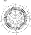
- FIG 1 shows a dynamo-electric rotary machine 1.
- the machine 1 has a stator 2 with a stator winding 11 .
- the machine 1 has a rotor 3 .
- the rotor 3 has an at least essentially cylindrical recess (see reference number 0 in figure 2 ).
- the recess is designed to accommodate a shaft 6 .
- the rotor 3 has a first material 8 and a second material 9 .
- the two materials 8, 9 are advantageously integrally connected to each other.
- the first material 8 is formed in a region of the rotor 3 in which a q-flux path 51, 52 of a magnetic Flux that can be generated by a magnetic stator field that can be generated by the stator winding 11 is located.
- the magnetic stator field and thus the magnetic flux are generated by energizing the stator winding 11 .
- the second material 9 is formed in a region of the rotor 3 in which there is a q-flux path 51, 52 of the magnetic flux.
- the first material 8 is advantageous, a material that facilitates the conduction of a magnetic flux.
- the first material 8 contains, for example, iron and/or cobalt or an alloy of iron or iron-cobalt.
- the first material 8 is advantageously arranged in the rotor 3 in such a way that on the one hand it conducts the magnetic flux of the stator field in the d-flux path 5 of the rotor 3 particularly well and on the other hand it conducts the magnetic flux of a permanent magnet in the q-flux path 51, 52 of the rotor 3 particularly well directs.
- the second material 9 is advantageously non-magnetic (in particular with a saturation induction of ⁇ 0.1 T) and represents a high resistance for the magnetic flux.
- the second material 9 advantageously has non-magnetic steel, for example E316.
- the second material 9 is advantageously arranged in the rotor 3 in such a way that it offers a high resistance to the magnetic flux of the stator field in the q-flux path of the rotor 3 and reduces magnetic leakage of the permanent magnets in the rotor 3 .
- FIG 20 shows an inner periphery and an outer periphery of the rotor 3.
- FIG 20 advantageously has the second material 9 .
- the material is advantageously non-magnetic.
- the figure also shows that on an outer circumference 57, 58, 59 of the rotor 3 there are a large number of areas which adjoin the outer circumference 57, 58, 59 of the rotor 3 and which advantageously contain the second material 9.
- the figure also shows a third material in the form of a permanent magnet 54, 55 and 56.
- the permanent magnet 54 borders on the area 57 and the area 20 in the figure.
- the permanent magnet 54 touches the area 57 and the area 20.
- the permanent magnet 54 is designed in the figure in the form of a rectangle.
- the areas 57 and 20 are advantageously formed at least in sections in such a way that they are flush with one side of the tangent rectangular permanent magnet 54 in each case. Precisely this can also be seen in the case of the rectangular permanent magnet 55 .
- Two areas 58 and 59 adjoining the outer circumference 57, 58, 59 are formed in sections in such a way that they are flush with one side of the rectangular permanent magnet 55 in each case.
- the magnets in the q-flux path of the rotor 3 advantageously generate their own magnetic field in the q-axis. On the other hand, they also generate magnetic resistance against the q-axis stator field.
- the high magnetic resistance advantageously means that the stator magnetic field can only develop to a small extent in the q-axis. This advantageously leads to high torque-current linearity and thus to high torques, which are formed by the permanent magnetic field and the stator magnetic field.
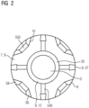
- FIG 2 shows a rotor position 7.
- the in FIG 1 The rotor 3 shown advantageously has a plurality of rotor layers 7 arranged one behind the other.
- the FIG 2 shows a rotor layer 7, which is made of at least two materials.
- the materials are advantageously bonded to one another, in particular by means of metal diffusion.
- a tensile strength of this connection is advantageously greater than 200 MPa at 200°C.
- the rotor lamination has a plurality of recesses.
- a recess for the shaft 6 is marked with 0.
- recesses for permanent magnets are marked with 540 and 550.
- the area surrounding the inner circumference of the rotor layer 7 can be designed as a ring or ring-shaped, as shown in the figure.
- the area 20 can have the same material as the areas 58, 59 arranged on the outer circumference.
- another material 12 in area 20 is also conceivable in order to increase tensile strength. This is, for example, high-alloy steel.
- the areas 58, 59 and 57 arranged on the outer circumference also increase the strength of the rotor layer 7.
- the figure shows a rotor position 7 through the in 6 described method can be produced.
- a plurality of these rotor layers 7 are advantageously joined together and then a prefabricated permanent magnet is inserted into the recesses 550, 540.
- the rotor positions 7 shown are z. B. for 16-pin Machines 1 (see also 9 ), especially a three-phase permanently excited synchronous machine. A number of poles p ⁇ 4 is advantageous.
- the area 20 has a plurality of star-shaped extensions 120, in particular made of soft magnetic material.
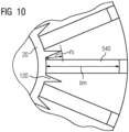
- a length ls of the star-shaped extension 120 (see 10 ) is advantageously between 20% and 100% of bm, bm describing a radial length of the recess 540.
- the recess 540 is filled with a magnet at a later point in time.
- This can, for example, be a ferrite magnet, in particular a ceramic ferrite magnet.
- a ferrite magnet in particular a ceramic ferrite magnet.
- NdFeB or SmCo magnets are also conceivable.
- the stator 2 in 9 has a three-phase winding.
- the magnetic coils are preferably designed as windings around individual teeth.
- the stator advantageously has a plurality of stator layers arranged one behind the other, which have soft magnetic material, preferably with a saturation induction of at least 2.1 T.
- a stator layer is preferably at least 50 ⁇ m and at most 200 ⁇ m thick.
- the stator layer is preferably thinner than 150 ⁇ m.
- the stator position is z. B. by means of a screen printing process or stencil printing process.
- the rotor position 7 is z. B. by means of a screen printing process or stencil printing process.
- a rotor layer is preferably at least 50 ⁇ m and at most 200 ⁇ m thick.
- the rotor layer is preferably thinner than 150 ⁇ m.
- the invention offers the advantage that the magnetic leakage flux due to the non-magnetic material in the rotor is very low.
- the machine 1 has a very high efficiency.
- the energy efficiency class IE5 can be achieved and even exceeded.
- the advantage over conventional asynchronous and synchronous reluctance motors is particularly clear for smaller machines (especially below 20 kW).
- the machine 1 has little mass and is cheaper.
- Ferrites also have the advantage that they are cheaper than rare earth magnets and have a lower CO2 equivalent. In addition, their availability is higher.
- a PM synchronous machine with ceramic ferrite magnets has particularly low losses because no eddy currents flow in the ceramic magnets.
- the copper losses in the stator are also reduced as a result of the significant reduction in the rotor-internal leakage flux.
- the rotor 3 shown is robust and rigid. It therefore has a long service life, low vibrations and low noise.
- the machine 1 is suitable for. B. for highly efficient industrial engines, but also for electromobility.
- the embodiment has radial magnets 38 .
- the area 20a surrounding the inner circumference is also shaped differently than in the previously shown embodiments.
- the region 20a is shown in the figure as an octagon with eight sides, four sides having a first length and another four sides having a second length, the second length being reduced from the first length. Two sides of equal length are arranged opposite one another in the figure.
- the rotor 3 shown in this embodiment is not completely round, but has circular segment sections that are filled with air L, for example.
- a non-magnetic material can also be inserted in this area marked with L.
- the rotor 3 has areas 37 which are arranged on the outer circumference 57 , 58 , 59 and which have the second material 9 .
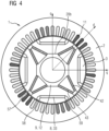
- FIG 4 shows an embodiment that has split radial magnets 42,43. This means that one side of the magnets 42, 43 borders on a region 57 and the respective other side of the permanent magnet 42 or 43 touches the region 20b surrounding the inner circumference at different points.
- the permanent magnets 42, 43 and 33 shown are slimmer in the figure than the magnets in, for example FIG 1 .
- FIG. 5 shows the dynamo-electric rotary machine 1, having a stator 2, a rotor 3 and a shaft 6.
- the described rotor 3 advantageously has a plurality of rotor layers 7 arranged one behind the other.
- the rotor layer 7 includes a plurality of areas that have different materials, but at least a first material and a second material.
- a first suspension comprising at least one binder and solid particles, is applied through a first template to a base area to obtain a first green body.
- the first template forms the areas that have the first material.
- a second template advantageously depicts the areas that have the second material.
- a second suspension comprising at least one binder and solid particles, is therefore applied through the second template onto a base surface to obtain a second green body.
- step S3 the binder can be expelled from the first green body.
- step S4 the binder can be expelled from the second green body.
- the binder is preferably expelled by means of debinding.
- step S5 the two green bodies are joined.
- the binder can be expelled after the green bodies have been joined in a method step S6.
- the respective binder from the first green body and/or the second (and/or additional) green body can be removed before joining in a method step S3 and a method step S4 of the first green body and the second green body (And/or others) and/or after assembly (see method step S6) are expelled.
- a permanent material connection between the two green bodies and the solid particles is created by heating and/or compression, in particular by means of sintering.
- step S8 the rotor layers 7 are joined together.
- step S9 permanent magnets are introduced into the recesses.
Landscapes
- Engineering & Computer Science (AREA)
- Power Engineering (AREA)
- Manufacturing & Machinery (AREA)
- Permanent Field Magnets Of Synchronous Machinery (AREA)
Abstract
Die Erfindung betrifft eine dynamoelektrische rotatorische Maschine (1), aufweisend: einen Stator (2) mit einer Statorwicklung (11); einen Rotor (3) mit einer wenigstens im Wesentlichen zylindrischen Ausnehmung (0) zur Aufnahme einer Welle (6); wobei der Rotor (3) ein erstes Material (8) und ein zweites Material (9) aufweist, wobei das erste Material (8) in einem Bereich des Rotors (3) ausgebildet ist, in welchem ein d-Flusspfad (5) eines magnetischen Flusses der von einem von der Statorwicklung (11) erzeugbaren magnetischen Statorfeld hervorrufbar ist, liegt, wobei das zweite Material (9) in einem Bereich des Rotors (3) ausgebildet ist, in welchem ein q-Flusspfad (51, 52) des magnetischen Flusses liegt.
Description
- Die Erfindung betrifft eine dynamoelektrische rotatorische Maschine.
- Bei Reluktanzmaschinen und permanenterregten Maschinen, insbesondere mit innenliegenden Magneten, sind oft Kompromisse zwischen Rotorfestigkeit bzw. Drehzahlfestigkeit und magnetischer Streuung nötig. Oft ist eine Drehzahl der Maschine durch eine geringe Rotorfestigkeit begrenzt oder eine Leistungs- und/oder eine Drehmomentdichte sind durch eine magnetische Streuung reduziert. Meist geht das Erreichen einer erwünschten Drehzahlfestigkeit zu Lasten der Leistungs- bzw. Drehmomentdichte.
- Der Erfindung liegt die Aufgabe zugrunde eine Maschine dahingehend zu verbessern.
- Die Lösung der Aufgabe gelingt durch Anspruch 1, d. h. eine dynamoelektrische rotatorische Maschine, aufweisend:
- einen Stator mit einer Statorwicklung,
- einen Rotor mit einer wenigstens im Wesentlichen zylindrischen Ausnehmung zur Aufnahme einer Welle,
- Das Statorfeld wird vorteilhaft durch Bestromung der Statorwicklung erzeugt.
- Vorteilhaft ist eine Ausführung, wonach das erste Material ein weichmagnetisches Material ist, beispielsweise Eisen und/oder Kobalt.
- Auch andere Materialien, insbesondere Materialien mit einer Sättigungsinduktion von wenigstens 2,1 T, sind möglich.
- Das erste Material dient der Führung des magnetischen Flusses. Das erste Material ist vorteilhaft so im Rotor angeordnet, dass es einerseits den magnetischen Fluss des Statorfeldes in der d-Flussrichtung des Rotors besonders gut leitet und andererseits den magnetischen Fluss der Permanentmagnete in der q-Flussrichtung des Rotors besonders gut leitet.
- Vorteilhaft ist eine Ausführung, wonach das zweite Material ein amagnetisches Material ist, beispielsweise amagnetischer Stahl, z.B. E316.
- Das zweite Material stellt für den magnetischen Fluss einen hohen Widerstand dar.
- Das Material ist vorteilhaft so im Rotor angeordnet, dass es dem magnetischen Fluss der Statormagnete in der q-Flussrichtung des Rotors einen hohen Widerstand bietet und die magnetische Streuung der PM-Magnete im Rotor reduziert.
- Vorteilhaft ist eine Ausführung, wonach der Rotor einen einen Innenumfang des Rotors umgebenden Bereich aufweist, in welchem das zweite Material ausgebildet ist.
- So kann eine gute Stabilität des Rotors, insbesondere in einem an eine Welle angrenzenden Bereich, erreicht werden.
- Vorteilhaft ist eine Ausführung, wonach der Rotor einen an einen Außenumfang des Rotors angrenzenden Bereich aufweist, in welchem das zweite Material ausgebildet ist.
- Auch dies wirkt sich positiv auf eine Drehzahlfestigkeit des Rotors aus.
- Vorteilhaft ist eine Ausführung, wonach zwischen dem den Innenumfang umgebenden Bereich und dem an den Außenumfang angrenzenden Bereich ein Bereich angeordnet ist, in welchem ein drittes Material ausgebildet ist.
- Vorteilhaft ist eine Ausführung, wonach das dritte Material ein permanentmagnetisches Material ist.
- Diese Ausführung ist vorteilhaft, da durch die Statormagnete hohe Reluktanzdrehmomente erzeugt werden können und zudem hohe Drehmomente im Zusammenwirken mit den Permanentmagneten erzeugt werden können.
- So kann eine hohe Drehmoment- bzw. Leistungsdichte erreicht werden.
- Vorzugsweise werden die Bereiche mit dem ersten Material und dem zweiten Material mittels Sieb- bzw. Schablonendruck hergestellt. Dies gelingt insbesondere durch das weiter unten erläuterte Verfahren. Vorzugsweise sind Aussparungen bzw. Ausnehmungen im Rotor vorhanden, in welchen vorzugsweise vorgefertigte Permanentmagnete eingebracht werden.
- Vorteilhaft ist eine Ausführung, wonach das dritte Material den Bereich, der den Innenumfang umgibt, und den Bereich, der an den Außenumfang angrenzt, tangiert.
- Diese Anordnung wird in der Figurenbeschreibung näher erläutert.
- Die Permanentmagnete werden so sicher fixiert. Vorzugsweise werden sie noch zusätzlich mit Klebstoff und/oder Harz fixiert.
- Vorteilhaft ist eine Ausführung, wonach der Bereich, in welchem ein drittes Material ausgebildet ist, in Form eines Rechtecks ausgebildet ist,
wobei der den Innenumfang umgebende Bereich wenigstens einen Abschnitt aufweist, der so geformt ist, dass er mit einer Seite des tangierenden rechteckigen Bereichs bündig ist. - Vorteilhaft ist eine Ausführung, wonach der am Außenumfang angrenzende Bereich wenigstens einen Abschnitt aufweist, der so geformt ist, dass er mit einer Seite des tangierenden rechteckigen Bereichs bündig ist.
- So können vorgefertigte Permanentmagnete verwendet werden und leicht in den Rotor eingeschoben bzw. eingepresst werden.
- Vorteilhaft ist eine Ausführung, wonach am Außenumfang angrenzend zwei weitere Bereiche ausgebildet sind, in welchen das zweite Material ausgebildet ist, wobei zwischen den weiteren Bereichen und diese tangierend ein weiterer Bereich ausgebildet ist, in welchem das dritte Material ausgebildet ist.
- Das dritte Material ist vorteilhaft im q-Flusspfad des Rotors angeordnet. Das dritte Material ist vorzugsweise in Form von Permanentmagneten vorhanden. Diese erzeugen einerseits ein eigenes magnetisches Feld in der q-Achse, anderseits erzeugen sie auch einen magnetischen Widerstand gegen das Statorfeld in der q-Achse.
- Die Reluktanzdrehmomente sind besonders groß, wenn die weichmagnetische Anisotropie des Rotors groß ist. Das wird vorteilhaft dadurch erreicht, dass im d-Pfad der magnetische Widerstand gering ist (z. B. wenig Luftspalte oder wenig amagnetisches Material) und wenn im q-Pfad viel amagnetisches Material vorhanden ist. Die Magnete wirken dann vorteilhaft wegen der geringen Permeabilität wie amagnetisches Material. Die Magnete bilden vorteilhaft durch ihren magnetischen Fluss auch Drehmomente. Dazu ist vorteilhaft im q-Pfad (bis auf die Magnete) wenig amagnetisches Material oder ein ausreichend großer Luftspalt ausgebildet
- Vorteilhaft ist eine Ausführung, wonach das erste Material und das zweite Material stoffschlüssig verbunden sind.
- So können stabile einzelne Rotorlagen geschaffen und somit ein drehzahlfester Rotor gebaut werden.
- Vorteilhaft ist eine Ausführung, wonach der den Innenumfang umgebende Bereich sternförmige Fortsätze aufweist.
- Dadurch wird der magnetische Streufluss im inneren Rotorbereich weiter reduziert und zudem die Festigkeit erhöht.
- Die Lösung der Aufgabe gelingt ferner durch einen Rotor für eine dynamoelektrische rotatorische Maschine, aufweisend eine Mehrzahl hintereinander angeordneter Materiallagen.
- Die Lösung der Aufgabe gelingt ferner durch ein Verfahren zur Herstellung eines derartigen Rotors, wobei eine Materiallage wenigstens einen ersten Bereich, aufweisend ein erstes Material, und wenigstens einen zweiten Bereich, aufweisend ein zweites Material, umfasst, wobei die Materiallage ferner wenigstens eine Aussparung umfasst, mit folgenden Schritten:
- Aufbringen einer ersten Suspension, aufweisend wenigstens ein Bindemittel und Festteilchen, durch eine erste Schablone auf eine Grundfläche zum Erhalt eines ersten Grünkörpers, wobei der erste Bereich von der ersten Schablone abgebildet wird,
- Aufbringen einer zweiten Suspension, aufweisend wenigstens ein Bindemittel und Festteilchen, durch eine zweite Schablone auf eine Grundfläche zum Erhalt eines zweiten Grünkörpers, wobei der zweite Bereich von der zweiten Schablone abgebildet wird,
- Zusammenfügen des ersten Grünkörpers und des zweiten Grünkörpers,
- Schaffen eines dauerhaften, stoffschlüssigen Zusammenhalts der beiden Grünkörper und der Festteilchen durch Erwärmung und/oder mittels Verdichtung, insbesondere mittels Sinterung, zur Bildung der Materiallage,
- Anordnen einer Mehrzahl an Materiallagen,
- Einfügen von Magnetmaterial, insbesondere vorgefertigtem Magnetmaterial, in die Ausnehmung.
- Im Folgenden wird die Erfindung anhand der in den Figuren dargestellten Ausführungsbeispiele näher beschrieben und erläutert.
- Es zeigen:
- FIG 1, 3, 4, 5 und 9
- Ausführungsformen einer dynamoelektrischen rotatorische Maschine,
- FIG 2, 7 und 8
- Ausführungsformen einer Rotorlage,
- FIG 6
- ein Verfahren,
- FIG 10
- einen Ausschnitt aus
FIG 8 -
FIG 1 zeigt eine dynamoelektrische rotatorische Maschine 1. - Die Maschine 1 weist einen Stator 2 mit einer Statorwicklung 11 auf. Zudem weist die Maschine 1 einen Rotor 3 auf. Der Rotor 3 weist eine wenigstens im Wesentlichen zylindrische Ausnehmung auf (siehe Bezugszeichen 0 in
Figur 2 ). Die Ausnehmung ist zur Aufnahme einer Welle 6 ausgebildet. Der Rotor 3 weist ein erstes Material 8 und ein zweites Material 9 auf. Die beiden Materialien 8, 9 (s.FIG 2 ) sind vorteilhaft stoffschlüssig miteinander verbunden. - Das erste Material 8 ist in einem Bereich des Rotors 3 ausgebildet, in welchem ein q-Flusspfad 51, 52 eines magnetischen Flusses, der von einem von der Statorwicklung 11 erzeugbaren magnetischen Statorfeld hervorrufbar ist, liegt. Das magnetische Statorfeld und somit der magnetische Fluss werden durch Bestromung der Statorwicklung 11 erzeugt.
- Das zweite Material 9 ist in einem Bereich des Rotors 3 ausgebildet, in welchem ein q-Flusspfad 51, 52 des magnetischen Flusses liegt.
- Vorteilhaft ist das erste Material 8, ein Material, das die Führung eines magnetischen Flusses erleichtert. Das erste Material 8 enthält beispielsweise Eisen und/oder Kobalt bzw. eine Legierung aus Eisen oder Eisenkobalt. Eine Sättigungsinduktion des Materials von mindestens 1,8 T, vorteilhaft mindestens 2,1 T, ist von Vorteil.
- Das erste Material 8 ist vorteilhaft derart im Rotor 3 angeordnet, dass es einerseits den magnetischen Fluss des Statorfeldes im d-Flusspfad 5 des Rotors 3 besonders gut leitet und andererseits den magnetischen Fluss eines Permanentmagneten im q-Flusspfad 51, 52 des Rotors 3 besonders gut leitet.
- Vorteilhaft ist das zweite Material 9 amagnetisch (insbesondere mit einer Sättigungsinduktion von ≤ 0,1 T) und stellt für den magnetischen Fluss einen hohen Widerstand dar.
- Vorteilhaft weist das zweite Material 9 amagnetischen Stahl, beispielsweise E316 auf.
- Das zweite Material 9 ist vorteilhaft so im Rotor 3 angeordnet, dass es den magnetischen Fluss des Statorfeldes im q-Flusspfad des Rotors 3 einen hohen Widerstand bietet und eine magnetische Streuung der Permanentmagnete im Rotor 3 reduziert.
- Die Figur zeigt einen Innenumfang und einen Außenumfang des Rotors 3. Ein den Innenumfang des Rotors 3 umgebender Bereich 20 weist vorteilhaft das zweite Material 9 auf. Das Material ist vorteilhaft amagnetisch.
- Zudem zeigt die Figur, dass an einem Außenumfang 57, 58, 59 des Rotors 3 eine Vielzahl von an den Außenumfang 57, 58, 59 des Rotors 3 angrenzende Bereiche vorhanden sind, welche vorteilhaft das zweite Material 9 enthalten.
- Die Figur zeigt zudem ein drittes Material in Form eines Permanentmagneten 54, 55 und 56. Der Permanentmagnet 54 grenzt in der Figur an den Bereich 57 und den Bereich 20 an. Der Permanentmagnet 54 tangiert den Bereich 57 und den Bereich 20. Der Permanentmagnet 54 ist in der Figur in Form eines Rechtecks ausgebildet.
- Die Bereiche 57 und 20 sind vorteilhaft wenigstens abschnittsweise derart ausgebildet, dass sie mit jeweils einer Seite des tangierenden rechteckigen Permanentmagneten 54 bündig sind. Eben dies ist auch beim rechteckig ausgebildeten Permanentmagneten 55 zu erkennen. Zwei an den Außenumfang 57, 58, 59 angrenzende Bereiche 58 und 59 sind abschnittsweise derart ausgebildet, dass sie mit jeweils einer Seite des rechteckigen Permanentmagneten 55 bündig sind.
- Alternativ kann der Bereich 20 auch ein weiteres Material 12 aufweisen, welches besonders zugfest ist (<=500 MPa). So können hohe Pressungen auf die Welle 6 ermöglicht werden und maximal zulässige Drehzahlen der Maschine erhöht werden.
- Die Magnete im q-Flusspfad des Rotors 3 erzeugen vorteilhaft ein eigenes magnetisches Feld in der q-Achse. Andererseits erzeugen sie auch einen magnetischen Widerstand gegen das Statorfeld der q-Achse.
- Der hohe magnetische Widerstand führt vorteilhaft dazu, dass sich das Statormagnetfeld in der q-Achse nur gering ausbilden kann. Dies führt vorteilhaft zu einer hohen Drehmoment-Strom-Linearität und somit zu hohen Drehmomenten, die durch Permanentmagnetfeld und Statormagnetfeld gebildet werden.
-
FIG 2 zeigt eine Rotorlage 7. Der inFIG 1 gezeigte Rotor 3 weist vorteilhaft eine Mehrzahl an hintereinander angeordneten Rotorlagen 7 auf. - Die
FIG 2 zeigt eine Rotorlage 7, welche aus wenigstens zwei Materialien gefertigt ist. - Die Materialien sind vorteilhaft stoffschlüssig, insbesondere mittels Metalldiffusion, miteinander verbunden. Eine Zugfestigkeit dieser Verbindung ist vorteilhaft größer als 200 MPa bei 200°C.
- Zudem weist das Rotorblech eine Mehrzahl an Aussparungen auf. Eine Aussparung für die Welle 6 ist mit 0 gekennzeichnet. Zudem sind Aussparungen für Permanentmagnete mit 540 und 550 gekennzeichnet. Der Bereich, der den Innenumfang der Rotorlage 7 umgibt, kann als Ring bzw. ringförmig ausgebildet sein, wie in der Figur gezeigt. Der Bereich 20 kann dasselbe Material wie am Außenumfang angeordnete Bereiche 58, 59 aufweisen. Jedoch ist auch ein weiteres Material 12 im Bereich 20 denkbar, um eine Zugfestigkeit zu erhöhen. Dies ist beispielsweise hochlegierter Stahl.
- Die am Außenumfang angeordneten Bereiche 58, 59 und 57 erhöhen auch eine Festigkeit der Rotorlage 7.
- Die Figur zeigt eine Rotorlage 7 die durch das in
FIG 6 beschriebene Verfahren herstellbar ist. - Vorteilhaft wird eine Mehrzahl dieser Rotorlagen 7 aneinandergefügt und anschließend ein vorgefertigter Permanentmagnet in die Aussparungen 550, 540 eingefügt.
-
FIG 7 und FIG 8 zeigen weitere mögliche Ausführungen der Rotorlage 7. Die gezeigten Rotorlagen 7 sind z. B. für 16-polige Maschinen 1 (siehe auchFIG 9 ), insbesondere eine dreiphasige permanenterregte Synchronmaschine, geeignet. Vorteilhaft ist eine Polzahl p ≥ 4. -
FIG 8 zeigt eine besondere Ausführungsform. Der Bereich 20 weist eine Mehrzahl an sternförmigen Fortsätzen 120, insbesondere aus weichmagnetischem Material, auf. - Eine Länge ls des sternförmigen Fortsatzes 120 (siehe
FIG 10 ) beträgt vorteilhaft zwischen 20% und 100% von bm, wobei bm eine radiale Länge der Aussparung 540 beschreibt. Vorteilhaft wird die Aussparung 540 zu einem späteren Zeitpunkt mit einem Magneten gefüllt. - Dies kann beispielsweise ein Ferritmagnet, insbesondere keramischer Ferritmagnet, sein. Jedoch sind auch NdFeB- oder SmCo-Magnete denkbar.
- Der Stator 2 in
FIG 9 weist eine dreiphasige Drehstromwicklung auf. Die Magnetspulen sind vorzugsweise als Wicklungen um Einzelzähne ausgeführt. Vorzugweise ist eine Anzahl der bewickelten Zähne = 18. - Vorteilhaft weist der Stator eine Mehrzahl an hintereinander angeordneten Statorlagen auf, welche weichmagnetisches Material aufweisen, vorzugsweise mit einer Sättigungsinduktion von wenigstens 2,1 T.
- Vorzugsweise ist eine Statorlage wenigstens 50 µm und höchstens 200 µm dick. Vorzugsweise ist die Statorlage dünner als 150 µm. Die Statorlage ist z. B. mittels eines Siebdruckverfahrens bzw. Schablonendruckverfahrens herstellbar.
- Auch die Rotorlage 7 ist z. B. mittels eines Siebdruckverfahrens bzw. Schablonendruckverfahrens herstellbar. Vorzugsweise ist eine Rotorlage wenigstens 50 µm und höchstens 200 µm dick. Vorzugsweise ist die Rotorlage dünner als 150 µm.
- Die Erfindung bietet den Vorteil, dass der magnetische Streufluss durch das amagnetische Material im Rotor sehr gering ist.
- Die in
FIG 9 gezeigte Ausführungsform weist besondere Vorteile auf: In dieser ragen vom inneren amagnetischen Ring 20 sternförmige Spitzen in die magnetischen Flussleitstücke. Dadurch wird der magnetische Streufluss im inneren Rotorbereich weiter reduziert und zudem die Festigkeit erhöht. - Die Maschine 1 hat einen sehr hohen Wirkungsgrad. Die Energieeffizienzklasse IE5 kann erreicht und sogar übertroffen werden. Besonders bei kleineren Maschinen (insb. unter 20 kW) ist der Vorteil gegenüber konventionellen Asynchron- und Synchronreluktanzmotoren deutlich.
- Insbesondere durch den Einsatz von Ferritmagneten hat die Maschine 1 wenig Masse und ist günstiger. Ferrite haben zudem den Vorteil, dass sie günstiger sind als Seltenerdmagnete und ein geringeres CO2-Äquivalent aufweisen. Zudem ist ihre Verfügbarkeit höher.
- Eine PM-Synchronmaschine mit keramischen Ferritmagneten hat besonders geringe Verluste, weil in den keramischen Magneten keine Wirbelströme fließen. Durch die deutliche Reduktion des rotorinternen Streuflusses werden auch die Kupferverluste im Stator reduziert.
- Der dargestellte Rotor 3 ist robust und steif. Somit hat er eine hohe Lebensdauer, geringe Schwingungen und geringe Geräusche.
- Die Maschine 1 eignet sich z. B. für hoch effiziente Industriemotoren, aber auch für die Elektromobilität.
-
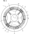
FIG 3 zeigt eine weitere Ausführungsform der Maschine 1. - Die Ausführungsform weist radiale Magnete 38 auf. Auch der den Innenumfang umgebende Bereich 20a ist anders geformt als in den bisher gezeigten Ausführungsformen. Der Bereich 20a ist in der Figur als Achteck mit acht Seiten ausgebildet, wobei vier Seiten eine erste Länge und weitere vier Seiten eine zweite Länge, wobei die zweite Länge gegenüber der ersten Länge verringert ist, aufweisen. Zwei gleich lange Seiten sind in der Figur gegenüberliegend angeordnet.
- Der in dieser Ausführungsform gezeigte Rotor 3 ist nicht ganz rund, sondern weist Kreissegmentabschnitte auf, die beispielsweise mit Luft L gefüllt sind. Alternativ kann in diesem mit L gekennzeichneten Bereich auch ein amagnetisches Material eingefügt sein.
- Der Rotor 3 weist am Außenumfang 57, 58, 59 angeordnete Bereiche 37 auf, welche das zweite Material 9 aufweisen.
-
FIG 4 zeigt eine Ausführungsform die geteilte radiale Magnete 42, 43 aufweist. Dies bedeutet, dass eine Seite der Magnete 42, 43 an einem Bereich 57 angrenzt und die jeweils andere Seite des Permanentmagneten 42 bzw. 43 den den Innenumfang umgebenden Bereich 20b an unterschiedlichen Stellen tangiert. - Die gezeigten Permanentmagnete 42, 43 und 33 sind in der Figur schlanker ausgeführt als die Magnete in beispielsweise
FIG 1 . -
FIG 5 zeigt die dynamoelektrische rotatorische Maschine 1, aufweisend einen Stator 2, einen Rotor 3 und eine Welle 6. -
FIG 6 zeigt ein Verfahren zur Herstellung einer Rotorlage 7. - Der beschriebene Rotor 3 weist vorteilhaft eine Mehrzahl an hintereinander angeordneten Rotorlagen 7 auf. Die Rotorlage 7 umfasst eine Mehrzahl an Bereichen, die unterschiedliche Materialien aufweisen, wenigstens jedoch ein erstes Material und ein zweites Material.
- In einem Verfahrensschritt S1 erfolgt ein Aufbringen einer ersten Suspension, aufweisend wenigstens ein Bindemittel und Festteilchen, durch eine erste Schablone auf eine Grundfläche zum Erhalt eines ersten Grünkörpers.
- Die erste Schablone bildet die Bereiche aus, die das erste Material aufweisen.
- Eine zweite Schablone bildet vorteilhaft die Bereiche ab, die das zweite Material aufweisen.
- In einem Verfahrensschritt S2 erfolgt demnach ein Aufbringen einer zweiten Suspension, aufweisend wenigstens ein Bindemittel und Festteilchen durch die zweite Schablone auf eine Grundfläche zum Erhalt eines zweiten Grünkörpers.
- In einem optionalen Verfahrensschritt S3 kann ein Austreiben des Bindemittels aus dem ersten Grünkörper erfolgen.
- In einem optionalen Verfahrensschritt S4 kann ein Austreiben des Bindemittels aus dem zweiten Grünkörper erfolgen.
- Das Austreiben des Bindemittels wird vorzugsweise mittels Entbinderung bewerkstelligt.
- In einem Verfahrensschritt S5 werden die beiden Grünkörper zusammengefügt.
- Alternativ oder zusätzlich kann das Austreiben des Bindemittels nach Zusammenfügung der Grünkörper in einem Verfahrensschritt S6 erfolgen.
- Es können somit verschiedene Vorgehensweisen verfolgt werden: Das jeweilige Bindemittel aus dem ersten Grünkörper und/oder dem zweiten (und/oder weiteren) Grünkörper kann vor dem Zusammenfügen in einem Verfahrensschritt S3 und einem Verfahrensschritt S4 des ersten Grünkörpers und des zweiten Grünkörpers (und/oder weiteren) und/oder nach dem Zusammenfügen (siehe Verfahrensschritt S6) ausgetrieben werden.
- In einem Verfahrensschritt S7 erfolgt ein Schaffen eines dauerhaften stoffschlüssigen Zusammenhalts der beiden Grünkörper und der Festteilchen, durch Erwärmung und/oder Verdichtung, insbesondere mittels Sinterung.
- In einem Verfahrensschritt S8 werden die Rotorlagen 7 aneinandergefügt.
- In einem Verfahrensschritt S9 werden Permanentmagnete in die Aussparungen eingebracht.
Claims (15)
- Dynamoelektrische rotatorische Maschine (1), aufweisend- einen Stator (2) mit einer Statorwicklung (11),- einen Rotor (3) mit einer wenigstens im Wesentlichen zylindrischen Ausnehmung (0) zur Aufnahme einer Welle (6), wobei der Rotor (3) ein erstes Material (8) und ein zweites Material (9) aufweist, wobei das erste Material (8) in einem Bereich des Rotors (3) ausgebildet ist, in welchem ein d-Flusspfad (5) eines magnetischen Flusses der von einem von der Statorwicklung (11) erzeugbaren magnetischen Statorfeld hervorrufbar ist, liegt, wobei das zweite Material (9) in einem Bereich des Rotors (3) ausgebildet ist, in welchem ein q-Flusspfad (51, 52) des magnetischen Flusses liegt.
- Dynamoelektrische rotatorische Maschine (1) nach Anspruch 1, wobei das erste Material (8) ein weichmagnetisches Material ist, beispielsweise Eisen und/oder Kobalt.
- Dynamoelektrische rotatorische Maschine (1) nach einem der vorhergehenden Ansprüche, wobei das zweite Material (9) ein amagnetisches Material ist, beispielsweise amagnetischer Stahl, z.B. E316.
- Dynamoelektrische rotatorische Maschine (1) nach einem der vorhergehenden Ansprüche, wobei der Rotor (3) einen einen Innenumfang des Rotors (3) umgebenden Bereich (20, 20a, 20b) aufweist, in welchem das zweite Material (9) ausgebildet ist.
- Dynamoelektrische rotatorische Maschine (1) nach einem der vorhergehenden Ansprüche, wobei der Rotor (3) einen an einen Außenumfang des Rotors (3) angrenzenden Bereich (57, 37, 41) aufweist, in welchem das zweite Material (9) ausgebildet ist.
- Dynamoelektrische rotatorische Maschine (1) nach einem der Ansprüche 4 oder 5, wobei zwischen dem den Innenumfang umgebenden Bereich (20, 20a, 20b) und dem an den Außenumfang angrenzenden Bereich (57, 37, 41) ein Bereich angeordnet ist, in welchem ein drittes Material (54, 38, 42, 43) ausgebildet ist.
- Dynamoelektrische rotatorische Maschine (1) nach Anspruch 6, wobei das dritte Material (54, 38, 42, 43) ein permanentmagnetisches Material ist.
- Dynamoelektrische rotatorische Maschine (1) nach einem der Ansprüche 6 oder 7, wobei das dritte Material (54, 38, 42, 43) den den Innenumfang umgebenden Bereich (20, 20a, 20b), und den an den Außenumfang angrenzenden Bereich (57, 37, 41) tangiert.
- Dynamoelektrische rotatorische Maschine (1) nach einem der Ansprüche 6 bis 8, wobei der Bereich (54, 38, 42, 43), in welchem das dritte Material ausgebildet ist, in Form eines Rechtecks ausgebildet ist, wobei der den Innenumfang umgebende Bereich (20, 20a, 20b) wenigstens einen Abschnitt aufweist, der so geformt ist, dass er mit einer Seite des tangierenden rechteckigen Bereichs bündig ist.
- Dynamoelektrische rotatorische Maschine (1) nach einem der Ansprüche 6 bis 9, wobei der am Außenumfang angrenzende Bereich (57, 37, 41) wenigstens einen Abschnitt aufweist, der so geformt ist, dass er mit einer Seite des tangierenden rechteckigen Bereichs bündig ist.
- Dynamoelektrische rotatorische Maschine (1) nach einem der Ansprüche 6 bis 10, wobei am Außenumfang angrenzend zwei weitere Bereiche (58, 59) ausgebildet sind, in welchen das zweite Material (9) ausgebildet ist, wobei zwischen den weiteren Bereichen (58, 59) und diese tangierend ein weiterer Bereich (33) ausgebildet ist, in welchem das dritte Material ausgebildet ist.
- Dynamoelektrische rotatorische Maschine (1) nach einem der vorhergehenden Ansprüche, wobei das erste Material (8) und das zweite Material (9) stoffschlüssig verbunden sind.
- Dynamoelektrische rotatorische Maschine (1) nach einem der vorhergehenden Ansprüche, wobei der den Innenumfang umgebende Bereich (20, 20a, 20b) sternförmige Fortsätze (120) aufweist.
- Rotor (3) für eine dynamoelektrische rotatorische Maschine (1) nach einem der Ansprüche 1 bis 13, aufweisend eine Mehrzahl hintereinander angeordneter Materiallagen.
- Verfahren zur Herstellung eines Rotors (3) nach Anspruch 14, wobei eine Materiallage wenigstens einen ersten Bereich, aufweisend ein erstes Material, und wenigstens einen zweiten Bereich, aufweisend ein zweites Material, umfasst, wobei die Materiallage ferner wenigstens eine Aussparung umfasst, mit folgenden Schritten:- Aufbringen einer ersten Suspension, aufweisend wenigstens ein Bindemittel und Festteilchen, durch eine erste Schablone auf eine Grundfläche zum Erhalt eines ersten Grünkörpers, wobei der erste Bereich von der ersten Schablone abgebildet wird,- Aufbringen einer zweiten Suspension, aufweisend wenigstens ein Bindemittel und Festteilchen, durch eine zweite Schablone auf eine Grundfläche zum Erhalt eines zweiten Grünkörpers, wobei der zweite Bereich von der zweiten Schablone abgebildet wird,- Zusammenfügen des ersten Grünkörpers und des zweiten Grünkörpers,- Schaffen eines dauerhaften, stoffschlüssigen Zusammenhalts der beiden Grünkörper und der Festteilchen durch Erwärmung und/oder mittels Verdichtung, insbesondere mittels Sinterung, zur Bildung der Materiallage,- Anordnen einer Mehrzahl an Materiallagen,- Einfügen von Magnetmaterial, insbesondere vorgefertigtem Magnetmaterial, in die Ausnehmung.
Priority Applications (2)
| Application Number | Priority Date | Filing Date | Title |
|---|---|---|---|
| EP22154011.5A EP4220900A1 (de) | 2022-01-28 | 2022-01-28 | Dynamoelektrische rotatorische maschine |
| PCT/EP2023/051048 WO2023143972A1 (de) | 2022-01-28 | 2023-01-18 | Dynamoelektrische rotatorische maschine |
Applications Claiming Priority (1)
| Application Number | Priority Date | Filing Date | Title |
|---|---|---|---|
| EP22154011.5A EP4220900A1 (de) | 2022-01-28 | 2022-01-28 | Dynamoelektrische rotatorische maschine |
Publications (1)
| Publication Number | Publication Date |
|---|---|
| EP4220900A1 true EP4220900A1 (de) | 2023-08-02 |
Family
ID=80122929
Family Applications (1)
| Application Number | Title | Priority Date | Filing Date |
|---|---|---|---|
| EP22154011.5A Pending EP4220900A1 (de) | 2022-01-28 | 2022-01-28 | Dynamoelektrische rotatorische maschine |
Country Status (2)
| Country | Link |
|---|---|
| EP (1) | EP4220900A1 (de) |
| WO (1) | WO2023143972A1 (de) |
Citations (5)
| Publication number | Priority date | Publication date | Assignee | Title |
|---|---|---|---|---|
| DE2538320A1 (de) * | 1974-08-30 | 1976-03-18 | Kollmorgen Corp Imd | Permanentmagnetischer laeufer fuer dynamoelektrische maschinen und verfahren zu dessen herstellung |
| US6429566B1 (en) * | 1999-11-10 | 2002-08-06 | Isuzu Motors Limited | Rotor of rotating machine |
| US20080265705A1 (en) * | 2003-08-02 | 2008-10-30 | Yukio Kinoshita | Rotary Machine and Electromagnetic Machine |
| EP2793366B1 (de) * | 2013-04-16 | 2016-03-02 | Siemens Aktiengesellschaft | Verfahren zum Herstellen eines Einzelsegmentläufers mit Hülsenvorrichtung und entsprechender Läufer |
| EP3595136A1 (de) * | 2018-07-13 | 2020-01-15 | Siemens Aktiengesellschaft | Robuste materiallagen |
-
2022
- 2022-01-28 EP EP22154011.5A patent/EP4220900A1/de active Pending
-
2023
- 2023-01-18 WO PCT/EP2023/051048 patent/WO2023143972A1/de unknown
Patent Citations (5)
| Publication number | Priority date | Publication date | Assignee | Title |
|---|---|---|---|---|
| DE2538320A1 (de) * | 1974-08-30 | 1976-03-18 | Kollmorgen Corp Imd | Permanentmagnetischer laeufer fuer dynamoelektrische maschinen und verfahren zu dessen herstellung |
| US6429566B1 (en) * | 1999-11-10 | 2002-08-06 | Isuzu Motors Limited | Rotor of rotating machine |
| US20080265705A1 (en) * | 2003-08-02 | 2008-10-30 | Yukio Kinoshita | Rotary Machine and Electromagnetic Machine |
| EP2793366B1 (de) * | 2013-04-16 | 2016-03-02 | Siemens Aktiengesellschaft | Verfahren zum Herstellen eines Einzelsegmentläufers mit Hülsenvorrichtung und entsprechender Läufer |
| EP3595136A1 (de) * | 2018-07-13 | 2020-01-15 | Siemens Aktiengesellschaft | Robuste materiallagen |
Also Published As
| Publication number | Publication date |
|---|---|
| WO2023143972A1 (de) | 2023-08-03 |
Similar Documents
| Publication | Publication Date | Title |
|---|---|---|
| WO2013135258A2 (de) | Elektrische maschine | |
| DE102015111480A1 (de) | Rotor und elektrische Maschine | |
| DE112016006772T5 (de) | Elektromotor und Klimaanlage | |
| DE112016006316T5 (de) | Magnetisierungsverfahren, Rotor, Motor und Scrollverdichter | |
| DE102015004669A1 (de) | Motor | |
| DE102011110879A1 (de) | Rotor und Verfahren zum Bilden desselben | |
| WO2016041857A1 (de) | Elektrische maschine mit geringer magnetischer nutstreuung | |
| AT522826A1 (de) | Rotor | |
| EP3309933A1 (de) | Statorpaket für elektrische maschine | |
| EP2838180B1 (de) | Läufer einer dynamoelektrischen rotatorischen Maschine | |
| EP2768117A1 (de) | Läufer einer Reluktanzmaschine | |
| DE102008022209A1 (de) | Wechselstrommotor | |
| DE1160080B (de) | Elektromagnetisches System, insbesondere fuer einen Gleichstrommotor | |
| EP4220900A1 (de) | Dynamoelektrische rotatorische maschine | |
| EP2722970A2 (de) | Läuferanordnung für eine permanentmagneterregte elektrische Maschine | |
| DE19525346C2 (de) | Ringkern-Synchronmaschine | |
| DE102012218993A1 (de) | Läuferanordnung für eine permanentmagneterregte elektrische Maschine | |
| WO2021250108A1 (de) | Elektrischer motor und verfahren zum betrieb eines elektrischen motors | |
| DE102016014526A1 (de) | Permanentmagnetrotor für eine elektrische Maschine | |
| DE102019122239A1 (de) | Stator | |
| WO2021063501A1 (de) | Permanenterregter rotor mit verbesserter magnetgeometrie | |
| WO2014060228A2 (de) | Läuferanordnung für eine permanentmagneterregte elektrische maschine | |
| DE102013202006A1 (de) | Läuferanordnung für eine permanentmagneterregte elektrische Maschine | |
| DE102015105991B4 (de) | Elektroarbeitsmaschine hoher Leistungsdichte | |
| DE102008002463A1 (de) | Klauenpolgenerator |
Legal Events
| Date | Code | Title | Description |
|---|---|---|---|
| PUAI | Public reference made under article 153(3) epc to a published international application that has entered the european phase |
Free format text: ORIGINAL CODE: 0009012 |
|
| STAA | Information on the status of an ep patent application or granted ep patent |
Free format text: STATUS: THE APPLICATION HAS BEEN PUBLISHED |
|
| AK | Designated contracting states |
Kind code of ref document: A1 Designated state(s): AL AT BE BG CH CY CZ DE DK EE ES FI FR GB GR HR HU IE IS IT LI LT LU LV MC MK MT NL NO PL PT RO RS SE SI SK SM TR |
|
| STAA | Information on the status of an ep patent application or granted ep patent |
Free format text: STATUS: THE APPLICATION IS DEEMED TO BE WITHDRAWN |