EP4220840A1 - Cylindrical secondary battery - Google Patents
Cylindrical secondary battery Download PDFInfo
- Publication number
- EP4220840A1 EP4220840A1 EP21872674.3A EP21872674A EP4220840A1 EP 4220840 A1 EP4220840 A1 EP 4220840A1 EP 21872674 A EP21872674 A EP 21872674A EP 4220840 A1 EP4220840 A1 EP 4220840A1
- Authority
- EP
- European Patent Office
- Prior art keywords
- cap
- vent
- cylindrical
- secondary battery
- bottom part
- Prior art date
- Legal status (The legal status is an assumption and is not a legal conclusion. Google has not performed a legal analysis and makes no representation as to the accuracy of the status listed.)
- Pending
Links
Images




Classifications
-
- H—ELECTRICITY
- H01—ELECTRIC ELEMENTS
- H01M—PROCESSES OR MEANS, e.g. BATTERIES, FOR THE DIRECT CONVERSION OF CHEMICAL ENERGY INTO ELECTRICAL ENERGY
- H01M50/00—Constructional details or processes of manufacture of the non-active parts of electrochemical cells other than fuel cells, e.g. hybrid cells
- H01M50/30—Arrangements for facilitating escape of gases
- H01M50/342—Non-re-sealable arrangements
-
- H—ELECTRICITY
- H01—ELECTRIC ELEMENTS
- H01M—PROCESSES OR MEANS, e.g. BATTERIES, FOR THE DIRECT CONVERSION OF CHEMICAL ENERGY INTO ELECTRICAL ENERGY
- H01M50/00—Constructional details or processes of manufacture of the non-active parts of electrochemical cells other than fuel cells, e.g. hybrid cells
- H01M50/30—Arrangements for facilitating escape of gases
- H01M50/342—Non-re-sealable arrangements
- H01M50/3425—Non-re-sealable arrangements in the form of rupturable membranes or weakened parts, e.g. pierced with the aid of a sharp member
-
- H—ELECTRICITY
- H01—ELECTRIC ELEMENTS
- H01M—PROCESSES OR MEANS, e.g. BATTERIES, FOR THE DIRECT CONVERSION OF CHEMICAL ENERGY INTO ELECTRICAL ENERGY
- H01M50/00—Constructional details or processes of manufacture of the non-active parts of electrochemical cells other than fuel cells, e.g. hybrid cells
- H01M50/10—Primary casings; Jackets or wrappings
- H01M50/102—Primary casings; Jackets or wrappings characterised by their shape or physical structure
- H01M50/107—Primary casings; Jackets or wrappings characterised by their shape or physical structure having curved cross-section, e.g. round or elliptic
-
- H—ELECTRICITY
- H01—ELECTRIC ELEMENTS
- H01M—PROCESSES OR MEANS, e.g. BATTERIES, FOR THE DIRECT CONVERSION OF CHEMICAL ENERGY INTO ELECTRICAL ENERGY
- H01M50/00—Constructional details or processes of manufacture of the non-active parts of electrochemical cells other than fuel cells, e.g. hybrid cells
- H01M50/10—Primary casings; Jackets or wrappings
- H01M50/147—Lids or covers
- H01M50/148—Lids or covers characterised by their shape
- H01M50/152—Lids or covers characterised by their shape for cells having curved cross-section, e.g. round or elliptic
-
- H—ELECTRICITY
- H01—ELECTRIC ELEMENTS
- H01M—PROCESSES OR MEANS, e.g. BATTERIES, FOR THE DIRECT CONVERSION OF CHEMICAL ENERGY INTO ELECTRICAL ENERGY
- H01M50/00—Constructional details or processes of manufacture of the non-active parts of electrochemical cells other than fuel cells, e.g. hybrid cells
- H01M50/10—Primary casings; Jackets or wrappings
- H01M50/147—Lids or covers
- H01M50/166—Lids or covers characterised by the methods of assembling casings with lids
- H01M50/167—Lids or covers characterised by the methods of assembling casings with lids by crimping
-
- H—ELECTRICITY
- H01—ELECTRIC ELEMENTS
- H01M—PROCESSES OR MEANS, e.g. BATTERIES, FOR THE DIRECT CONVERSION OF CHEMICAL ENERGY INTO ELECTRICAL ENERGY
- H01M50/00—Constructional details or processes of manufacture of the non-active parts of electrochemical cells other than fuel cells, e.g. hybrid cells
- H01M50/10—Primary casings; Jackets or wrappings
- H01M50/147—Lids or covers
- H01M50/166—Lids or covers characterised by the methods of assembling casings with lids
- H01M50/169—Lids or covers characterised by the methods of assembling casings with lids by welding, brazing or soldering
-
- H—ELECTRICITY
- H01—ELECTRIC ELEMENTS
- H01M—PROCESSES OR MEANS, e.g. BATTERIES, FOR THE DIRECT CONVERSION OF CHEMICAL ENERGY INTO ELECTRICAL ENERGY
- H01M50/00—Constructional details or processes of manufacture of the non-active parts of electrochemical cells other than fuel cells, e.g. hybrid cells
- H01M50/10—Primary casings; Jackets or wrappings
- H01M50/147—Lids or covers
- H01M50/166—Lids or covers characterised by the methods of assembling casings with lids
- H01M50/171—Lids or covers characterised by the methods of assembling casings with lids using adhesives or sealing agents
-
- H—ELECTRICITY
- H01—ELECTRIC ELEMENTS
- H01M—PROCESSES OR MEANS, e.g. BATTERIES, FOR THE DIRECT CONVERSION OF CHEMICAL ENERGY INTO ELECTRICAL ENERGY
- H01M50/00—Constructional details or processes of manufacture of the non-active parts of electrochemical cells other than fuel cells, e.g. hybrid cells
- H01M50/30—Arrangements for facilitating escape of gases
-
- H—ELECTRICITY
- H01—ELECTRIC ELEMENTS
- H01M—PROCESSES OR MEANS, e.g. BATTERIES, FOR THE DIRECT CONVERSION OF CHEMICAL ENERGY INTO ELECTRICAL ENERGY
- H01M50/00—Constructional details or processes of manufacture of the non-active parts of electrochemical cells other than fuel cells, e.g. hybrid cells
- H01M50/30—Arrangements for facilitating escape of gases
- H01M50/308—Detachable arrangements, e.g. detachable vent plugs or plug systems
-
- H—ELECTRICITY
- H01—ELECTRIC ELEMENTS
- H01M—PROCESSES OR MEANS, e.g. BATTERIES, FOR THE DIRECT CONVERSION OF CHEMICAL ENERGY INTO ELECTRICAL ENERGY
- H01M50/00—Constructional details or processes of manufacture of the non-active parts of electrochemical cells other than fuel cells, e.g. hybrid cells
- H01M50/50—Current conducting connections for cells or batteries
- H01M50/572—Means for preventing undesired use or discharge
- H01M50/574—Devices or arrangements for the interruption of current
- H01M50/578—Devices or arrangements for the interruption of current in response to pressure
-
- H—ELECTRICITY
- H01—ELECTRIC ELEMENTS
- H01M—PROCESSES OR MEANS, e.g. BATTERIES, FOR THE DIRECT CONVERSION OF CHEMICAL ENERGY INTO ELECTRICAL ENERGY
- H01M2200/00—Safety devices for primary or secondary batteries
- H01M2200/20—Pressure-sensitive devices
-
- Y—GENERAL TAGGING OF NEW TECHNOLOGICAL DEVELOPMENTS; GENERAL TAGGING OF CROSS-SECTIONAL TECHNOLOGIES SPANNING OVER SEVERAL SECTIONS OF THE IPC; TECHNICAL SUBJECTS COVERED BY FORMER USPC CROSS-REFERENCE ART COLLECTIONS [XRACs] AND DIGESTS
- Y02—TECHNOLOGIES OR APPLICATIONS FOR MITIGATION OR ADAPTATION AGAINST CLIMATE CHANGE
- Y02E—REDUCTION OF GREENHOUSE GAS [GHG] EMISSIONS, RELATED TO ENERGY GENERATION, TRANSMISSION OR DISTRIBUTION
- Y02E60/00—Enabling technologies; Technologies with a potential or indirect contribution to GHG emissions mitigation
- Y02E60/10—Energy storage using batteries
Definitions
- An embodiment of the present invention relates to a cylindrical secondary battery.
- a cylindrical secondary battery includes a cylindrical electrode assembly, a cylindrical can accommodating the electrode assembly and an electrolyte, and a cap assembly coupled to an upper opening of the can to seal the can and allowing current generated in the electrode assembly to flow to an external device.
- a beading part and a crimping part are formed by applying a pressure along an upper outer circumferential surface of the can.
- the pressure is applied inward from the outside to the can, deformation of the cap assembly is likely to occur.
- sealing force of the secondary battery is lowered, and an overall height of the secondary battery is also changed.
- An embodiment of the present invention provides a cylindrical secondary battery capable of preventing component deformation during a manufacturing process or during use.
- a cylindrical secondary battery includes: a cylindrical can; an electrode assembly accommodated in the cylindrical can; and a cap assembly configured to cover the cylindrical can so as to seal the electrode assembly, wherein the cap assembly includes a cap-up, a cap-down below the cap-up, and a safety vent between the cap-up and the cap-down, wherein a mutual contact ratio between safety vent and the cap-down may range from 60% to 100%.
- the safety vent may include: a vent contact part that is in contact with the cap-up; a vent inclined part inclined downward from the vent contact part; a vent bottom part extending in parallel from the vent inclined part; and a vent protrusion protruding from the vent bottom part so as to be in contact with the cap-down.
- a diameter of the vent protrusion may be 60% to 100% of a diameter of the vent bottom part.
- the vent bottom part may further include a flat vent groove part formed in a top surface thereof facing the vent protrusion.
- the cap-down may include a cap-down through-hole passing through the cap-down, and the vent protrusion may cover a portion of the cap-down through-hole.
- the vent protrusion may be welded to the cap-down.
- the vent bottom part may further include a line-shaped vent groove part formed in a top surface thereof facing the vent protrusion.
- the cap-down may further include a flat cap-down groove part formed in a bottom surface thereof, and a diameter of the vent protrusion may be greater than a diameter of the flat cap-down groove part.
- the embodiment of the present invention may provide the cylindrical secondary battery capable of preventing the component deformation during the manufacturing process or during the use.
- the interconnection area between the safety vent and the cap-down is approximately 40% to approximately 100% of the area of the bottom part of the safety vent to prevent the deformation of the components such as the cap assembly during the manufacturing process or during the use, thereby providing the secondary battery, in which the sealing performance is not deteriorated, and the overall height thereof is not changed.
- first As used herein, terms such as "first,” “second,” etc. are used to describe various members, components, areas, layers, and/or portions. However, it is obvious that the members, components, areas, layers, and/or portions should not be defined by these terms. The terms do not mean a particular order, up and down, or superiority, and are used only for distinguishing one member, component, area, layer, or portion from another member, component, area, layer, or portion. Thus, a first member, component, area, layer, or portion which will be described may also refer to a second member, component, area, layer, or portion, without departing from the teaching of the present invention.
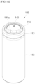
- FIGS. 1a , 1b , and 1c are perspective, cross-sectional, and exploded perspective views of a cylindrical secondary battery 100 according to an embodiment of the present invention.
- the secondary battery 100 includes a cylindrical can 110, an electrode assembly 120, and a cap assembly 140.
- a center pin 130 coupled to the electrode assembly 120 may be further provided.
- the cylindrical can 110 may include a circular bottom part 111 and a cylindrical side part 112 extending by a predetermined length upward from the bottom part 111. During a process of manufacturing the secondary battery, an upper portion of the cylindrical can 110 is opened. Thus, during the process of assembling the secondary battery, the electrode assembly 120 may be inserted into the cylindrical can 110 together with an electrolyte.
- the cylindrical can 110 may include steel, steel alloy, aluminum, an aluminum alloy, or an equivalent thereof.
- a beading part 113 recessed inward may be formed at a lower portion of the cylindrical can 110 with respect to the cap assembly 140 to prevent the electrode assembly 120 and the cap assembly 140 from being separated to the outside, and a crimping part 114 bent inward may be formed at an upper portion of the cylindrical can 110 with respect to the cap assembly 140.
- the electrode assembly 120 may be accommodated inside the cylindrical can 110.
- the electrode assembly 120 may include a negative electrode plate 121 coated with a negative electrode active material (e.g., graphite, carbon, etc.), a positive electrode plate 122 coated with a positive electrode active material (e.g., transition metal oxide (LiCoO 2 , LiNiO 2 , LiMn 2 O 4 , etc.)), and a separator 123 disposed between the negative electrode plate 121 and the positive electrode plate 122 to prevent short circuit from occurring and allowing lithium ions to move only.
- the negative electrode plate 121, the positive electrode plate 122, and the separator 123 may be wound in a substantially cylindrical shape.
- the negative plate 121 may include copper (Cu) or nickel (Ni) foil
- the positive plate 122 may include aluminum (Al) foil
- the separator 123 may include polyethylene (PE) or polypropylene (PP).
- a negative electrode tab 124 protruding downward by a predetermined length may be welded to a positive electrode tab 125 protruding upward by a predetermined length, but vice versa.
- the negative electrode tab 124 may include a copper or nickel material
- the positive electrode tab 125 may include an aluminum material.
- the negative electrode tab 124 of the electrode assembly 120 may be welded to the bottom part 111 of the cylindrical can 110.
- the cylindrical can 110 may act as a negative electrode.
- the positive electrode tab 125 may be welded to the bottom part 111 of the cylindrical can 110, and in this case, the cylindrical can 110 may operate as the positive electrode.
- a first insulating plate 126 coupled to the cylindrical can 110 and having a first hole 126a at a center thereof and a second hole 126b formed at the outside thereof may be interposed between the electrode assembly 120 and the bottom part 111.
- the first insulating plate 126 may serve to prevent the electrode assembly 120 from being in electrical contact with the bottom part 111 of the cylindrical can 110.
- the first insulating plate 126 may serve to prevent the positive electrode plate 122 of the electrode assembly 120 from being in electrical contact with the bottom part 111.
- the first hole 126a may serve to allow a gas to quickly move upward through the center pin 130 when a large amount of gas is generated due to abnormality in the secondary battery
- the second hole 126b may serve to allow the negative electrode tab 124 to pass therethrough so as to be welded to the bottom part 111.
- a second insulating plate 127 coupled to the cylindrical can 110 and having a first hole 127a at a center thereof and a plurality of second holes 126b formed in the outside thereof may be interposed between the electrode assembly 120 and the bottom portion 140.
- the second insulating plate 127 may serve to prevent the electrode assembly 120 from being in electrical contact with the cap assembly 140.
- the second insulating plate 127 may serve to prevent the negative electrode plate 121 of the electrode assembly 120 from being in electrical contact with the cap assembly 140.
- the first hole 127a may serve to allow a gas to quickly move to the cap assembly 140 when a large amount of gas is generated due to abnormality in the secondary battery
- the second hole 126b may serve to allow the positive electrode tab 125 to pass therethrough so as to be welded to the cap assembly 140.
- the rest second hole 127b may serve to allow the electrolyte to quickly flow into the electrode assembly 120 during a process of injecting the electrolyte.
- each of the first holes 126a and 127a of the first and second insulating plates 126 and 127 may have a diameter less than that of the center pin 130 so that the center pin 130 does not in electrical contact with the bottom part 111 of the cylindrical can 110 or the cap assembly 140 by an external impact.
- the center pin 130 may have a hollow circular pipe shape and may be coupled to the approximately center of the electrode assembly 120.
- the center pin 130 may include steel, a steel alloy, aluminum, an aluminum alloy, or polybutylene terepthalate.
- the center pin 130 serves to suppress deformation of the electrode assembly 120 during charging and discharging of the battery and serves as a passage for a gas generated inside the secondary battery. In some cases, the center pin 130 may be omitted.
- the cap assembly 140 may include a cap-up 141 having a plurality of through-holes 141a, a safety vent 142 disposed under the cap-up 141, a connection ring 143 disposed below the safety vent 142, and a cap-down 144 disposed below the safety vent 142 and the connection ring 143, having a plurality of through-holes 144a, and electrically connected to the positive electrode tab 125.
- the cap assembly 140 may further include an insulating gasket 145 that insulates the cap-up 141, the safety vent 143, and the cap-down 144 from the side part 111 of the cylindrical can 110.
- the insulating gasket 145 may be substantially compressed between the beading part 113 and the crimping part 114, which are formed on the side part of the cylindrical can 110.
- the through-holes 141a of the cap-up 141 and the through-holes 144a of the cap-down 144 may be configured to discharge an internal gas to the outside when an abnormal internal pressure is generated inside the cylindrical can 110.
- the internal gas may reverse the safety vent 143 upward through the through-holes 144a of the cap-down 144 so that the safety vent 143 is electrically disconnected from the cap-down 144, and then, as the safety vent 144 is torn, the internal gas may be discharged to the outside through the through-holes 141a of the cap-up 141.
- an electrolyte (not shown in the drawing) may be injected inside the cylindrical can 110 to serve so that lithium ions generated by electrochemical reaction in the negative electrode plate 121 and the positive electrode plate 122 inside the battery during the charging and discharging is movable.
- the electrolyte may include a non-aqueous organic electrolyte that is a mixture of lithium salt and a high-purity organic solvent.
- the electrolyte may include a polymer using a polymer electrolyte or a solid electrolyte.
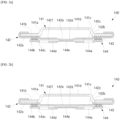
- FIGS. 2a to 2d are cross-sectional view illustrating a cap assembly 140 of a cylindrical secondary battery 100 according to Comparative Example and Embodiment of the present invention.
- FIG. 3 is a table summarizing whether the cap assembly 140 of the cylindrical secondary battery 100 is deformed according to Embodiment and Comparative Example of the present invention.
- FIG. 2a corresponds to Comparative Example 1 of FIG. 3
- FIG. 2b corresponds to Comparative Example 2 of FIG. 3
- FIG. 2c corresponds to Embodiment 2 of FIG. 3
- FIG. 2d corresponds to Embodiment 3 of FIG. 3 .
- the cap assembly 140 may include a cap-up 141, a safety vent 142 disposed under the cap-up 141, a connection ring disposed below the safety vent 142, and a cap-down disposed below the connection ring 143.
- a mutual contact (connection) ratio between the safety vent 142 and the cap-down 144 may range of approximately 60% and approximately 100%.
- the cap-up 141 may include a cap-up contact part 141b that is in contact with the safety vent 142, a cap-up inclined part 141c inclined upward from the cap-up contact part 141b and having a plurality of through-holes 141a, and a cap-up ceiling part 141d extending in parallel from the cap-up inclined part 141c.
- an external device may be electrically connected to the cap-up ceiling part 141d.
- the safety vent 142 may include a vent contact part 142a that is in contact with the cap-up contact part 141b of the cap-up 141, a vent inclined part 142b inclined downward from the vent contact part 142a, a vent bottom part 142c extending in parallel from the vent inclined part 142b, and a vent protrusion 142d protruding from the vent bottom part 142c so as to be in contact (connected) with the cap-down 144.
- a diameter (length or width) of the vent protrusion 142d may range of approximately 60% and approximately 100% of a diameter (length or width) of the vent bottom part 142c.
- the vent protrusion 142d may be welded to the cap-down 144 by laser or ultrasonic waves, and thus, the vent protrusion 142d and the cap-down 144 may be in contact (connected) with each other.
- the vent contact part 142a may be bent multiple times to be in contact with each of bottom, side, and top surfaces of the cap-up contact part 141b.
- the vent bottom part 142c may further include a substantially flat vent groove part 142e formed in a top surface thereof facing the vent protrusion 142d.
- the flat vent groove part 142e may be formed by pressing a mold for forming the vent protrusion 142d in the vent bottom part 142c.
- the vent bottom part 142c of the safety vent 142 may further include a substantially line-shaped vent groove 142f formed in a top surface facing the vent protrusion 142d.
- the line-shaped vent groove 142f may be ruptured when a pressure inside the battery is higher than a preset pressure to discharge the internal gas to the outside.
- the cap-down 144 may include a cap-down contact part 144b that is in contact with the connection ring 143, a cap-down inclined part 144c that is inclined downward from the cap-down contact part 144b, and a cap-down bottom part 144d extending in parallel from the cap-down inclined part 144c.
- the connection ring 143 may be interposed between the vent contact part 142a and the cap-down contact part 144b.
- each of the cap-up 141, the safety vent 142, and the cap-down 144 may include a metal material (e.g., copper, nickel, or aluminum), but the connection ring 143 may include an insulating material (e.g., polypropylene or polyethylene).
- the cap-down bottom part 144d may further include a through-hole 144a passing through the cap-down bottom part 144d.
- the vent protrusion 142d may cover a portion of the through-hole 144a (see FIG. 2d ).
- the cap-down 144 may further include a flat cap-down groove part 144e formed in a bottom surface.
- a diameter (length or width) of the vent protrusion 142d may be greater than a diameter (length or width) of the flat cap-down groove part 144e.
- the negative tab 125 (see FIG. 1b ) may be welded to the cap-down bottom part 144d that is outside of the flat cap-down groove part 144e.
- the diameter (length) of the vent bottom part 142c may be approximately 11.04 mm, and the diameter (length) of the vent protruding portion 142d may be approximately 3.28 mm.
- a mutual contact length (diameter) between the vent bottom part 142c and the cap-down bottom part 144d may be approximately 3.28 mm, and a mutual contact (connection) ratio may be approximately 29.7%.
- the diameter (length) of the vent bottom part 142c may be approximately 11.04 mm, and the diameter (length) of the vent protruding portion 142d may be approximately 4.5 mm.
- a mutual contact length (diameter) between the vent bottom part 142c and the cap-down bottom part 144d may be approximately 4.5 mm, and a mutual contact (connection) ratio may be approximately 40.8%.
- the diameter (length) of the vent bottom part 142c may be approximately 11.04 mm, and the diameter (length) of the vent protruding portion 142d may be approximately 7.5 mm.
- a mutual contact length (diameter) between the vent bottom part 142c and the cap-down bottom part 144d may be approximately 7.5 mm, and a mutual contact (connection) ratio may be approximately 67.9%.
- the diameter (length) of the vent bottom part 142c may be approximately 11.04 mm, and the diameter (length) of the vent protruding portion 142d may be approximately 9.6 mm.
- a mutual contact length (diameter) between the vent bottom part 142c and the cap-down bottom part 144d may be approximately 9.6 mm, and a mutual contact (connection) ratio may be approximately 87.0%.
- a usage amount (contact amount) of the cap-down bottom part 144d relative to the vent bottom part 142c is less than approximately 60% (i.e., Comparative Example 1 to 5)
- deformation was found in the cap assembly 140 after beading and crimping processes of the secondary battery 100.
- the deformation was not found in the cap assembly 140 after the beading and crimping processes of the secondary battery 100.
- a length (mm) of the vent bottom part may include a diameter of the vent bottom part 142c
- a contact length (mm) may include a contact diameter between the vent protrusion 142d and the cap-down bottom part 144d
- the usage amount (%) may include a ratio of the contact length between the vent protrusion 142d and the cap-down bottom part 144d to the length of the vent bottom part 142c.
- the length of the vent bottom part 142c may be approximately 11.04 mm
- the contact length that is, the lengths of the vent protrusion 142d may be 3.28 mm, 4.5 mm, 5.5 mm, 6.0 mm, 6.5 mm in Comparative Examples 1 to 5, respectively, and may be 7.0 mm, 7.5 mm, 9.6 mm, and 11.0 mm in Embodiments 1 to 4, respectively.
- the usage amounts may be 29.7%, 40.08%, 49.8%, 54.3%, and 58.9% in Comparative Examples 1 to 5, respectively, and may be 63.7%, 67.9%, 87.0%, and 100.0% in Embodiments 1 to 4, respectively.
- the mutual contact ratio between the safety vent and the cap-down may be preferably 60% to 100%.
- the embodiments of the present invention may provide the cylindrical secondary battery 100 capable of preventing the deformation of the cap assembly 140 during the manufacturing process or during the use.
- the mutual contact ratio between the safety vent 142 and the cap-down 144 may range of approximately 40% and approximately 100% relative to the area of the vent bottom part 142c to prevent the deformation of the cap assembly 140 during the manufacturing process or during the use, thereby providing the secondary battery, in which the sealing performance is not deteriorated, and the overall height thereof is not changed.
Landscapes
- Chemical & Material Sciences (AREA)
- Chemical Kinetics & Catalysis (AREA)
- Electrochemistry (AREA)
- General Chemical & Material Sciences (AREA)
- Sealing Battery Cases Or Jackets (AREA)
- Gas Exhaust Devices For Batteries (AREA)
Abstract
Description
- An embodiment of the present invention relates to a cylindrical secondary battery.
- In general, a cylindrical secondary battery includes a cylindrical electrode assembly, a cylindrical can accommodating the electrode assembly and an electrolyte, and a cap assembly coupled to an upper opening of the can to seal the can and allowing current generated in the electrode assembly to flow to an external device.
- In order to prevent the electrode assembly and the cap assembly from moving, a beading part and a crimping part are formed by applying a pressure along an upper outer circumferential surface of the can. Here, since the pressure is applied inward from the outside to the can, deformation of the cap assembly is likely to occur. Particularly, when the cap assembly is deformed, sealing force of the secondary battery is lowered, and an overall height of the secondary battery is also changed.
- The above-described information disclosed in the technology that serves as the background of the present invention is only for improving understanding of the background of the present invention and thus may include information that does not constitute the related art.
- An embodiment of the present invention provides a cylindrical secondary battery capable of preventing component deformation during a manufacturing process or during use.
- A cylindrical secondary battery according to an embodiment of the present invention includes: a cylindrical can; an electrode assembly accommodated in the cylindrical can; and a cap assembly configured to cover the cylindrical can so as to seal the electrode assembly, wherein the cap assembly includes a cap-up, a cap-down below the cap-up, and a safety vent between the cap-up and the cap-down, wherein a mutual contact ratio between safety vent and the cap-down may range from 60% to 100%.
- The safety vent may include: a vent contact part that is in contact with the cap-up; a vent inclined part inclined downward from the vent contact part; a vent bottom part extending in parallel from the vent inclined part; and a vent protrusion protruding from the vent bottom part so as to be in contact with the cap-down.
- A diameter of the vent protrusion may be 60% to 100% of a diameter of the vent bottom part.
- The vent bottom part may further include a flat vent groove part formed in a top surface thereof facing the vent protrusion.
- The cap-down may include a cap-down through-hole passing through the cap-down, and the vent protrusion may cover a portion of the cap-down through-hole.
- The vent protrusion may be welded to the cap-down.
- The vent bottom part may further include a line-shaped vent groove part formed in a top surface thereof facing the vent protrusion.
- The cap-down may further include a flat cap-down groove part formed in a bottom surface thereof, and a diameter of the vent protrusion may be greater than a diameter of the flat cap-down groove part.
- The embodiment of the present invention may provide the cylindrical secondary battery capable of preventing the component deformation during the manufacturing process or during the use. In some examples, the interconnection area between the safety vent and the cap-down is approximately 40% to approximately 100% of the area of the bottom part of the safety vent to prevent the deformation of the components such as the cap assembly during the manufacturing process or during the use, thereby providing the secondary battery, in which the sealing performance is not deteriorated, and the overall height thereof is not changed.
-
-
FIGS. 1a ,1b , and1c are perspective, cross-sectional, and exploded perspective views of a cylindrical secondary battery according to an embodiment of the present invention. -
FIGS. 2a to 2d are cross-sectional view illustrating a cap assembly of a cylindrical secondary battery according to Comparative Example and Embodiment of the present invention. -
FIG. 3 is a table summarizing whether the cap assembly of the cylindrical secondary battery is deformed according to Embodiment and Comparative Example of the present invention. - The present invention may, however, be embodied in many different forms and should not be construed as being limited to the embodiments set forth herein; rather, these embodiments are provided so that those skilled in the art thoroughly understand the present invention. Rather, these embodiments are provided so that this disclosure will be thorough and complete, and will fully convey the scope of the present invention to those skilled in the art.
- In addition, in the following drawings, the thickness or size of each layer is exaggerated for convenience and clarity of description, and the same reference numerals in the drawings refer to the same elements. As used herein, the term "and/or" includes any and all combinations of one or more of the associated listed items. In this specification, it will also be understood that when a member A is referred to as being connected to a member B, the member A can be directly connected to the member B or indirectly connected to the member B with a member B therebetween.
- The terms used herein are for illustrative purposes of the present invention only and should not be construed to limit the meaning or the scope of the present invention. As used in this specification, a singular form may, unless definitely indicating a particular case in terms of the context, include a plural form. Also, the expressions "comprise/include" and/or "comprising/including" used in this specification neither define the mentioned shapes, numbers, steps, operations, members, elements, and/or groups of these, nor exclude the presence or addition of one or more other different shapes, numbers, steps, operations, members, elements, and/or groups of these, or addition of these. The term "and/or" used herein includes any and all combinations of one or more of the associated listed items.
- As used herein, terms such as "first," "second," etc. are used to describe various members, components, areas, layers, and/or portions. However, it is obvious that the members, components, areas, layers, and/or portions should not be defined by these terms. The terms do not mean a particular order, up and down, or superiority, and are used only for distinguishing one member, component, area, layer, or portion from another member, component, area, layer, or portion. Thus, a first member, component, area, layer, or portion which will be described may also refer to a second member, component, area, layer, or portion, without departing from the teaching of the present invention.
- Spatially relative terms, such as "below", "beneath", "lower", "above", "upper" and the like, may be used herein for ease of description to describe one element or feature's relationship to another element(s) or feature(s) as illustrated in the figures. These spatially relative terms are intended for easy comprehension of the prevent invention according to various process states or usage states of the prevent invention, and thus, the present invention is not limited thereto. For example, an element or feature shown in the drawings is turned inside out, the element or feature described as "beneath" or "below" may change into "above" or "upper". Thus, the term "lower" may encompass the term "upper" or "below".
-
FIGS. 1a ,1b , and1c are perspective, cross-sectional, and exploded perspective views of a cylindricalsecondary battery 100 according to an embodiment of the present invention. - Referring to
FIGS. 1a ,1b , and1c , thesecondary battery 100 according to the present invention includes acylindrical can 110, anelectrode assembly 120, and acap assembly 140. In some examples, acenter pin 130 coupled to theelectrode assembly 120 may be further provided. - The
cylindrical can 110 may include acircular bottom part 111 and acylindrical side part 112 extending by a predetermined length upward from thebottom part 111. During a process of manufacturing the secondary battery, an upper portion of thecylindrical can 110 is opened. Thus, during the process of assembling the secondary battery, theelectrode assembly 120 may be inserted into the cylindrical can 110 together with an electrolyte. In some examples, the cylindrical can 110 may include steel, steel alloy, aluminum, an aluminum alloy, or an equivalent thereof. In some examples, in thecylindrical can 110, abeading part 113 recessed inward may be formed at a lower portion of thecylindrical can 110 with respect to thecap assembly 140 to prevent theelectrode assembly 120 and thecap assembly 140 from being separated to the outside, and a crimpingpart 114 bent inward may be formed at an upper portion of thecylindrical can 110 with respect to thecap assembly 140. - The
electrode assembly 120 may be accommodated inside thecylindrical can 110. Theelectrode assembly 120 may include anegative electrode plate 121 coated with a negative electrode active material (e.g., graphite, carbon, etc.), apositive electrode plate 122 coated with a positive electrode active material (e.g., transition metal oxide (LiCoO2, LiNiO2, LiMn2O4, etc.)), and aseparator 123 disposed between thenegative electrode plate 121 and thepositive electrode plate 122 to prevent short circuit from occurring and allowing lithium ions to move only. In some examples, thenegative electrode plate 121, thepositive electrode plate 122, and theseparator 123 may be wound in a substantially cylindrical shape. In some examples, thenegative plate 121 may include copper (Cu) or nickel (Ni) foil, thepositive plate 122 may include aluminum (Al) foil, and theseparator 123 may include polyethylene (PE) or polypropylene (PP). In some examples, in thenegative electrode plate 121, anegative electrode tab 124 protruding downward by a predetermined length may be welded to apositive electrode tab 125 protruding upward by a predetermined length, but vice versa. In some examples, thenegative electrode tab 124 may include a copper or nickel material, and thepositive electrode tab 125 may include an aluminum material. - In some examples, the
negative electrode tab 124 of theelectrode assembly 120 may be welded to thebottom part 111 of the cylindrical can 110. Thus, the cylindrical can 110 may act as a negative electrode. Of course, on the contrary, thepositive electrode tab 125 may be welded to thebottom part 111 of the cylindrical can 110, and in this case, the cylindrical can 110 may operate as the positive electrode. - In some examples, a first insulating
plate 126 coupled to thecylindrical can 110 and having afirst hole 126a at a center thereof and asecond hole 126b formed at the outside thereof may be interposed between theelectrode assembly 120 and thebottom part 111. The first insulatingplate 126 may serve to prevent theelectrode assembly 120 from being in electrical contact with thebottom part 111 of thecylindrical can 110. In some examples, the first insulatingplate 126 may serve to prevent thepositive electrode plate 122 of theelectrode assembly 120 from being in electrical contact with thebottom part 111. In some examples, thefirst hole 126a may serve to allow a gas to quickly move upward through thecenter pin 130 when a large amount of gas is generated due to abnormality in the secondary battery, and thesecond hole 126b may serve to allow thenegative electrode tab 124 to pass therethrough so as to be welded to thebottom part 111. - In some examples, a second insulating
plate 127 coupled to thecylindrical can 110 and having afirst hole 127a at a center thereof and a plurality ofsecond holes 126b formed in the outside thereof may be interposed between theelectrode assembly 120 and thebottom portion 140. The second insulatingplate 127 may serve to prevent theelectrode assembly 120 from being in electrical contact with thecap assembly 140. In some examples, the second insulatingplate 127 may serve to prevent thenegative electrode plate 121 of theelectrode assembly 120 from being in electrical contact with thecap assembly 140. In some examples, thefirst hole 127a may serve to allow a gas to quickly move to thecap assembly 140 when a large amount of gas is generated due to abnormality in the secondary battery, and thesecond hole 126b may serve to allow thepositive electrode tab 125 to pass therethrough so as to be welded to thecap assembly 140. In addition, the restsecond hole 127b may serve to allow the electrolyte to quickly flow into theelectrode assembly 120 during a process of injecting the electrolyte. - In some examples, each of the
first holes plates center pin 130 so that thecenter pin 130 does not in electrical contact with thebottom part 111 of the cylindrical can 110 or thecap assembly 140 by an external impact. - In some examples, the
center pin 130 may have a hollow circular pipe shape and may be coupled to the approximately center of theelectrode assembly 120. In some examples, thecenter pin 130 may include steel, a steel alloy, aluminum, an aluminum alloy, or polybutylene terepthalate. Thecenter pin 130 serves to suppress deformation of theelectrode assembly 120 during charging and discharging of the battery and serves as a passage for a gas generated inside the secondary battery. In some cases, thecenter pin 130 may be omitted. - The
cap assembly 140 may include a cap-up 141 having a plurality of through-holes 141a, asafety vent 142 disposed under the cap-up 141, aconnection ring 143 disposed below thesafety vent 142, and a cap-down 144 disposed below thesafety vent 142 and theconnection ring 143, having a plurality of through-holes 144a, and electrically connected to thepositive electrode tab 125. In some examples, thecap assembly 140 may further include an insulatinggasket 145 that insulates the cap-up 141, thesafety vent 143, and the cap-down 144 from theside part 111 of thecylindrical can 110. - In some examples, the insulating
gasket 145 may be substantially compressed between thebeading part 113 and the crimpingpart 114, which are formed on the side part of thecylindrical can 110. In some examples, the through-holes 141a of the cap-up 141 and the through-holes 144a of the cap-down 144 may be configured to discharge an internal gas to the outside when an abnormal internal pressure is generated inside thecylindrical can 110. In some examples, the internal gas may reverse thesafety vent 143 upward through the through-holes 144a of the cap-down 144 so that thesafety vent 143 is electrically disconnected from the cap-down 144, and then, as thesafety vent 144 is torn, the internal gas may be discharged to the outside through the through-holes 141a of the cap-up 141. - In some examples, an electrolyte (not shown in the drawing) may be injected inside the cylindrical can 110 to serve so that lithium ions generated by electrochemical reaction in the
negative electrode plate 121 and thepositive electrode plate 122 inside the battery during the charging and discharging is movable. The electrolyte may include a non-aqueous organic electrolyte that is a mixture of lithium salt and a high-purity organic solvent. In some examples, the electrolyte may include a polymer using a polymer electrolyte or a solid electrolyte. -
FIGS. 2a to 2d are cross-sectional view illustrating acap assembly 140 of a cylindricalsecondary battery 100 according to Comparative Example and Embodiment of the present invention.FIG. 3 is a table summarizing whether thecap assembly 140 of the cylindricalsecondary battery 100 is deformed according to Embodiment and Comparative Example of the present invention. Here,FIG. 2a corresponds to Comparative Example 1 ofFIG. 3 ,FIG. 2b corresponds to Comparative Example 2 ofFIG. 3 ,FIG. 2c corresponds toEmbodiment 2 ofFIG. 3 , andFIG. 2d corresponds toEmbodiment 3 ofFIG. 3 . - As illustrated in
FIGS. 2a to 2d , thecap assembly 140 may include a cap-up 141, asafety vent 142 disposed under the cap-up 141, a connection ring disposed below thesafety vent 142, and a cap-down disposed below theconnection ring 143. In some examples, a mutual contact (connection) ratio between thesafety vent 142 and the cap-down 144 may range of approximately 60% and approximately 100%. - In some examples, the cap-
up 141 may include a cap-upcontact part 141b that is in contact with thesafety vent 142, a cap-upinclined part 141c inclined upward from the cap-upcontact part 141b and having a plurality of through-holes 141a, and a cap-upceiling part 141d extending in parallel from the cap-upinclined part 141c. In some examples, an external device may be electrically connected to the cap-upceiling part 141d. - In some examples, the
safety vent 142 may include avent contact part 142a that is in contact with the cap-upcontact part 141b of the cap-up 141, a ventinclined part 142b inclined downward from thevent contact part 142a, a ventbottom part 142c extending in parallel from the vent inclinedpart 142b, and avent protrusion 142d protruding from the ventbottom part 142c so as to be in contact (connected) with the cap-down 144. - In some examples, a diameter (length or width) of the
vent protrusion 142d may range of approximately 60% and approximately 100% of a diameter (length or width) of the ventbottom part 142c. In some examples, thevent protrusion 142d may be welded to the cap-down 144 by laser or ultrasonic waves, and thus, thevent protrusion 142d and the cap-down 144 may be in contact (connected) with each other. - In some examples, the
vent contact part 142a may be bent multiple times to be in contact with each of bottom, side, and top surfaces of the cap-upcontact part 141b. In some examples, the ventbottom part 142c may further include a substantially flatvent groove part 142e formed in a top surface thereof facing thevent protrusion 142d. In some examples, the flatvent groove part 142e may be formed by pressing a mold for forming thevent protrusion 142d in the ventbottom part 142c. In some examples, the ventbottom part 142c of thesafety vent 142 may further include a substantially line-shapedvent groove 142f formed in a top surface facing thevent protrusion 142d. In some examples, the line-shapedvent groove 142f may be ruptured when a pressure inside the battery is higher than a preset pressure to discharge the internal gas to the outside. - In some examples, the cap-down 144 may include a cap-
down contact part 144b that is in contact with theconnection ring 143, a cap-downinclined part 144c that is inclined downward from the cap-down contact part 144b, and a cap-downbottom part 144d extending in parallel from the cap-downinclined part 144c. In some examples, theconnection ring 143 may be interposed between thevent contact part 142a and the cap-down contact part 144b. In some examples, each of the cap-up 141, thesafety vent 142, and the cap-down 144 may include a metal material (e.g., copper, nickel, or aluminum), but theconnection ring 143 may include an insulating material (e.g., polypropylene or polyethylene). - In some examples, the cap-down
bottom part 144d may further include a through-hole 144a passing through the cap-downbottom part 144d. In some examples, thevent protrusion 142d may cover a portion of the through-hole 144a (seeFIG. 2d ). In some examples, the cap-down 144 may further include a flat cap-downgroove part 144e formed in a bottom surface. Here, a diameter (length or width) of thevent protrusion 142d may be greater than a diameter (length or width) of the flat cap-downgroove part 144e. In some examples, the negative tab 125 (seeFIG. 1b ) may be welded to the cap-downbottom part 144d that is outside of the flat cap-downgroove part 144e. - For example, in
FIG. 2a (Comparative Example 1), the diameter (length) of the ventbottom part 142c may be approximately 11.04 mm, and the diameter (length) of thevent protruding portion 142d may be approximately 3.28 mm. Thus, a mutual contact length (diameter) between the ventbottom part 142c and the cap-downbottom part 144d may be approximately 3.28 mm, and a mutual contact (connection) ratio may be approximately 29.7%. - For example, in
FIG. 2b (Comparative Example 2), the diameter (length) of the ventbottom part 142c may be approximately 11.04 mm, and the diameter (length) of thevent protruding portion 142d may be approximately 4.5 mm. Thus, a mutual contact length (diameter) between the ventbottom part 142c and the cap-downbottom part 144d may be approximately 4.5 mm, and a mutual contact (connection) ratio may be approximately 40.8%. - For example, in
FIG. 2c (Embodiment 2), the diameter (length) of the ventbottom part 142c may be approximately 11.04 mm, and the diameter (length) of thevent protruding portion 142d may be approximately 7.5 mm. Thus, a mutual contact length (diameter) between the ventbottom part 142c and the cap-downbottom part 144d may be approximately 7.5 mm, and a mutual contact (connection) ratio may be approximately 67.9%. - For example, in
FIG. 2d (Embodiment 3), the diameter (length) of the ventbottom part 142c may be approximately 11.04 mm, and the diameter (length) of thevent protruding portion 142d may be approximately 9.6 mm. Thus, a mutual contact length (diameter) between the ventbottom part 142c and the cap-downbottom part 144d may be approximately 9.6 mm, and a mutual contact (connection) ratio may be approximately 87.0%. - As illustrated in
FIG. 3 , when a usage amount (contact amount) of the cap-downbottom part 144d relative to the ventbottom part 142c (or an amount of use of the ventbottom part 142c relative to the cap-downbottom part 144d) is less than approximately 60% (i.e., Comparative Example 1 to 5), deformation was found in thecap assembly 140 after beading and crimping processes of thesecondary battery 100. - However, when the usage amount (contact amount) of the cap-down
bottom part 144d relative to the ventbottom part 142c (or the amount of use of the ventbottom part 142c relative to the cap-downbottom part 144d) is approximately 60% to 100% (i.e.,Embodiments 1 to 4), the deformation was not found in thecap assembly 140 after the beading and crimping processes of thesecondary battery 100. - In
FIG. 3 , a length (mm) of the vent bottom part may include a diameter of the ventbottom part 142c, and a contact length (mm) may include a contact diameter between thevent protrusion 142d and the cap-downbottom part 144d. In addition, the usage amount (%) may include a ratio of the contact length between thevent protrusion 142d and the cap-downbottom part 144d to the length of the ventbottom part 142c. - In some examples, as illustrated in
FIG. 3 , the length of the ventbottom part 142c may be approximately 11.04 mm, and the contact length, that is, the lengths of thevent protrusion 142d may be 3.28 mm, 4.5 mm, 5.5 mm, 6.0 mm, 6.5 mm in Comparative Examples 1 to 5, respectively, and may be 7.0 mm, 7.5 mm, 9.6 mm, and 11.0 mm inEmbodiments 1 to 4, respectively. In addition, the usage amounts may be 29.7%, 40.08%, 49.8%, 54.3%, and 58.9% in Comparative Examples 1 to 5, respectively, and may be 63.7%, 67.9%, 87.0%, and 100.0% inEmbodiments 1 to 4, respectively. - As illustrated in
FIG. 3 , in Comparative Examples 1 to 5, the deformation occurred in the cap assembly during the battery manufacturing process, and inEmbodiments 1 to 4, the deformation did not occur in the cap assembly during the battery manufacturing process. Therefore, the mutual contact ratio between the safety vent and the cap-down may be preferably 60% to 100%. - In this manner, the embodiments of the present invention may provide the cylindrical
secondary battery 100 capable of preventing the deformation of thecap assembly 140 during the manufacturing process or during the use. In some examples, the mutual contact ratio between thesafety vent 142 and the cap-down 144 may range of approximately 40% and approximately 100% relative to the area of the ventbottom part 142c to prevent the deformation of thecap assembly 140 during the manufacturing process or during the use, thereby providing the secondary battery, in which the sealing performance is not deteriorated, and the overall height thereof is not changed. - The above-mentioned embodiment is merely an embodiment, and thus, the present invention is not limited to the foregoing embodiment, and also it will be understood by those of ordinary skill in the art that various changes in form and details may be made therein without departing from the spirit and scope of the present invention as defined by the following claims.
Claims (8)
- A cylindrical secondary battery comprising:a cylindrical can;an electrode assembly accommodated in the cylindrical can; anda cap assembly configured to cover the cylindrical can so as to seal the electrode assembly,wherein the cap assembly comprises a cap-up, a cap-down below the cap-up, and a safety vent between the cap-up and the cap-down, wherein a mutual contact ratio between safety vent and the cap-down ranges from 60% to 100%.
- The cylindrical secondary battery of claim 1, wherein the safety vent comprises:a vent contact part that is in contact with the cap-up;a vent inclined part inclined downward from the vent contact part;a vent bottom part extending in parallel from the vent inclined part; anda vent protrusion protruding from the vent bottom part so as to be in contact with the cap-down.
- The cylindrical secondary battery of claim 2, wherein a diameter of the vent protrusion is 60% to 100% of a diameter of the vent bottom part.
- The cylindrical secondary battery of claim 2, wherein the vent bottom part further comprises a flat vent groove part formed in a top surface thereof facing the vent protrusion.
- The cylindrical secondary battery of claim 2, wherein the cap-down comprises a cap-down through-hole passing through the cap-down, and
the vent protrusion covers a portion of the cap-down through-hole. - The cylindrical secondary battery of claim 2, wherein the vent protrusion is welded to the cap-down.
- The cylindrical secondary battery of claim 2, wherein the vent bottom part further comprises a line-shaped vent groove part formed in a top surface thereof facing the vent protrusion.
- The cylindrical secondary battery of claim 2, wherein the cap-down further comprises a flat cap-down groove part formed in a bottom surface thereof, and
a diameter of the vent protrusion is greater than a diameter of the flat cap-down groove part.
Applications Claiming Priority (2)
| Application Number | Priority Date | Filing Date | Title |
|---|---|---|---|
| KR1020200124929A KR20220041551A (en) | 2020-09-25 | 2020-09-25 | Cylindrical secondary battery |
| PCT/KR2021/008186 WO2022065637A1 (en) | 2020-09-25 | 2021-06-29 | Cylindrical secondary battery |
Publications (2)
| Publication Number | Publication Date |
|---|---|
| EP4220840A1 true EP4220840A1 (en) | 2023-08-02 |
| EP4220840A4 EP4220840A4 (en) | 2025-06-18 |
Family
ID=80846756
Family Applications (1)
| Application Number | Title | Priority Date | Filing Date |
|---|---|---|---|
| EP21872674.3A Pending EP4220840A4 (en) | 2020-09-25 | 2021-06-29 | Cylindrical secondary battery |
Country Status (5)
| Country | Link |
|---|---|
| US (1) | US20230361392A1 (en) |
| EP (1) | EP4220840A4 (en) |
| KR (1) | KR20220041551A (en) |
| CN (1) | CN116325308B (en) |
| WO (1) | WO2022065637A1 (en) |
Family Cites Families (11)
| Publication number | Priority date | Publication date | Assignee | Title |
|---|---|---|---|---|
| JP3649491B2 (en) * | 1995-11-10 | 2005-05-18 | Fdk株式会社 | Batteries with explosion-proof function |
| JPH09199105A (en) * | 1996-01-19 | 1997-07-31 | Matsushita Electric Ind Co Ltd | Explosion-proof sealing plate for secondary battery |
| JP4244580B2 (en) * | 2002-07-22 | 2009-03-25 | パナソニック株式会社 | Sealed battery |
| JP2004158303A (en) * | 2002-11-06 | 2004-06-03 | Sony Corp | Battery and power supply |
| JP4590856B2 (en) * | 2003-11-14 | 2010-12-01 | 新神戸電機株式会社 | Sealed battery |
| KR101293208B1 (en) * | 2010-03-22 | 2013-08-05 | 주식회사 엘지화학 | Cap assembly for secondary battery |
| KR101281038B1 (en) * | 2010-12-07 | 2013-07-09 | 주식회사 엘지화학 | Cap assembly and secondary battery using the same |
| KR101744092B1 (en) * | 2013-04-18 | 2017-06-20 | 삼성에스디아이 주식회사 | Rechargeable battery having minute current transprting member |
| KR102347978B1 (en) * | 2017-07-28 | 2022-01-07 | 주식회사 엘지에너지솔루션 | Secondary battery |
| KR102335696B1 (en) * | 2017-11-01 | 2021-12-07 | 주식회사 엘지에너지솔루션 | The Current Interrupt Device And The Cap Assembly |
| KR102906872B1 (en) * | 2020-03-17 | 2026-01-02 | 삼성에스디아이 주식회사 | secondary battery |
-
2020
- 2020-09-25 KR KR1020200124929A patent/KR20220041551A/en not_active Ceased
-
2021
- 2021-06-29 WO PCT/KR2021/008186 patent/WO2022065637A1/en not_active Ceased
- 2021-06-29 EP EP21872674.3A patent/EP4220840A4/en active Pending
- 2021-06-29 US US18/245,875 patent/US20230361392A1/en active Pending
- 2021-06-29 CN CN202180064937.3A patent/CN116325308B/en active Active
Also Published As
| Publication number | Publication date |
|---|---|
| CN116325308A (en) | 2023-06-23 |
| KR20220041551A (en) | 2022-04-01 |
| EP4220840A4 (en) | 2025-06-18 |
| WO2022065637A1 (en) | 2022-03-31 |
| CN116325308B (en) | 2026-03-24 |
| US20230361392A1 (en) | 2023-11-09 |
Similar Documents
| Publication | Publication Date | Title |
|---|---|---|
| US12199295B2 (en) | Secondary battery | |
| JP5137291B2 (en) | Lithium ion secondary battery | |
| EP4468506A1 (en) | Secondary battery | |
| US20240097291A1 (en) | Cylindrical lithium ion secondary battery | |
| EP3748728A1 (en) | Cylindrical lithium ion secondary battery | |
| KR102410911B1 (en) | Electrode assembly and secondary battery comprising the same | |
| EP3951915B1 (en) | Secondary battery | |
| EP4106064A1 (en) | Electrode assembly and secondary battery comprising same | |
| KR20190098495A (en) | Electrode assembly and secondary battery comprising the same | |
| CN116368667B (en) | Cylindrical secondary battery | |
| EP3726622A1 (en) | Secondary battery | |
| CN116325328B (en) | Cylindrical secondary battery | |
| KR102666014B1 (en) | Method of manufacturing cylindricality can for secondary battery and secondary battery comprising the same | |
| EP4175031A1 (en) | Cylindrical secondary battery and method for manufacturing the same | |
| EP4262010A1 (en) | Secondary battery | |
| KR102809614B1 (en) | Cylindrical secondary battery and manufacturing method of secondary battery | |
| US20230361392A1 (en) | Cylindrical secondary battery | |
| EP4311005A1 (en) | Secondary battery | |
| KR102963061B1 (en) | Electrode Assembly for Secondary Battery and Cylindrical Secondary Battery comprising the same | |
| KR102917067B1 (en) | Secondary battery | |
| US20240234970A1 (en) | Cylindrical secondary battery | |
| KR20250151028A (en) | Cylinder type rechargeable battery | |
| KR20230055753A (en) | Cylindrical Secondary Battery | |
| KR20250102764A (en) | Electrode assembly and rechargeable battery comprising the same |
Legal Events
| Date | Code | Title | Description |
|---|---|---|---|
| STAA | Information on the status of an ep patent application or granted ep patent |
Free format text: STATUS: THE INTERNATIONAL PUBLICATION HAS BEEN MADE |
|
| PUAI | Public reference made under article 153(3) epc to a published international application that has entered the european phase |
Free format text: ORIGINAL CODE: 0009012 |
|
| STAA | Information on the status of an ep patent application or granted ep patent |
Free format text: STATUS: REQUEST FOR EXAMINATION WAS MADE |
|
| 17P | Request for examination filed |
Effective date: 20230323 |
|
| AK | Designated contracting states |
Kind code of ref document: A1 Designated state(s): AL AT BE BG CH CY CZ DE DK EE ES FI FR GB GR HR HU IE IS IT LI LT LU LV MC MK MT NL NO PL PT RO RS SE SI SK SM TR |
|
| DAV | Request for validation of the european patent (deleted) | ||
| DAX | Request for extension of the european patent (deleted) | ||
| A4 | Supplementary search report drawn up and despatched |
Effective date: 20250516 |
|
| RIC1 | Information provided on ipc code assigned before grant |
Ipc: H01M 50/578 20210101ALI20250512BHEP Ipc: H01M 50/30 20210101ALI20250512BHEP Ipc: H01M 50/171 20210101ALI20250512BHEP Ipc: H01M 50/169 20210101ALI20250512BHEP Ipc: H01M 50/167 20210101ALI20250512BHEP Ipc: H01M 50/107 20210101ALI20250512BHEP Ipc: H01M 50/152 20210101ALI20250512BHEP Ipc: H01M 50/342 20210101AFI20250512BHEP |