EP4220834A1 - Battery pack - Google Patents
Battery pack Download PDFInfo
- Publication number
- EP4220834A1 EP4220834A1 EP22215659.8A EP22215659A EP4220834A1 EP 4220834 A1 EP4220834 A1 EP 4220834A1 EP 22215659 A EP22215659 A EP 22215659A EP 4220834 A1 EP4220834 A1 EP 4220834A1
- Authority
- EP
- European Patent Office
- Prior art keywords
- battery cells
- battery pack
- side portion
- bottom portion
- battery
- Prior art date
- Legal status (The legal status is an assumption and is not a legal conclusion. Google has not performed a legal analysis and makes no representation as to the accuracy of the status listed.)
- Granted
Links
Images


Classifications
-
- H—ELECTRICITY
- H01—ELECTRIC ELEMENTS
- H01M—PROCESSES OR MEANS, e.g. BATTERIES, FOR THE DIRECT CONVERSION OF CHEMICAL ENERGY INTO ELECTRICAL ENERGY
- H01M10/00—Secondary cells; Manufacture thereof
- H01M10/60—Heating or cooling; Temperature control
- H01M10/61—Types of temperature control
- H01M10/613—Cooling or keeping cold
-
- H—ELECTRICITY
- H01—ELECTRIC ELEMENTS
- H01M—PROCESSES OR MEANS, e.g. BATTERIES, FOR THE DIRECT CONVERSION OF CHEMICAL ENERGY INTO ELECTRICAL ENERGY
- H01M10/00—Secondary cells; Manufacture thereof
- H01M10/60—Heating or cooling; Temperature control
- H01M10/62—Heating or cooling; Temperature control specially adapted for specific applications
- H01M10/625—Vehicles
-
- H—ELECTRICITY
- H01—ELECTRIC ELEMENTS
- H01M—PROCESSES OR MEANS, e.g. BATTERIES, FOR THE DIRECT CONVERSION OF CHEMICAL ENERGY INTO ELECTRICAL ENERGY
- H01M10/00—Secondary cells; Manufacture thereof
- H01M10/60—Heating or cooling; Temperature control
- H01M10/64—Heating or cooling; Temperature control characterised by the shape of the cells
- H01M10/647—Prismatic or flat cells, e.g. pouch cells
-
- H—ELECTRICITY
- H01—ELECTRIC ELEMENTS
- H01M—PROCESSES OR MEANS, e.g. BATTERIES, FOR THE DIRECT CONVERSION OF CHEMICAL ENERGY INTO ELECTRICAL ENERGY
- H01M10/00—Secondary cells; Manufacture thereof
- H01M10/60—Heating or cooling; Temperature control
- H01M10/65—Means for temperature control structurally associated with the cells
- H01M10/653—Means for temperature control structurally associated with the cells characterised by electrically insulating or thermally conductive materials
-
- H—ELECTRICITY
- H01—ELECTRIC ELEMENTS
- H01M—PROCESSES OR MEANS, e.g. BATTERIES, FOR THE DIRECT CONVERSION OF CHEMICAL ENERGY INTO ELECTRICAL ENERGY
- H01M10/00—Secondary cells; Manufacture thereof
- H01M10/60—Heating or cooling; Temperature control
- H01M10/65—Means for temperature control structurally associated with the cells
- H01M10/655—Solid structures for heat exchange or heat conduction
-
- H—ELECTRICITY
- H01—ELECTRIC ELEMENTS
- H01M—PROCESSES OR MEANS, e.g. BATTERIES, FOR THE DIRECT CONVERSION OF CHEMICAL ENERGY INTO ELECTRICAL ENERGY
- H01M10/00—Secondary cells; Manufacture thereof
- H01M10/60—Heating or cooling; Temperature control
- H01M10/65—Means for temperature control structurally associated with the cells
- H01M10/655—Solid structures for heat exchange or heat conduction
- H01M10/6556—Solid parts with flow channel passages or pipes for heat exchange
-
- H—ELECTRICITY
- H01—ELECTRIC ELEMENTS
- H01M—PROCESSES OR MEANS, e.g. BATTERIES, FOR THE DIRECT CONVERSION OF CHEMICAL ENERGY INTO ELECTRICAL ENERGY
- H01M10/00—Secondary cells; Manufacture thereof
- H01M10/60—Heating or cooling; Temperature control
- H01M10/65—Means for temperature control structurally associated with the cells
- H01M10/656—Means for temperature control structurally associated with the cells characterised by the type of heat-exchange fluid
- H01M10/6567—Liquids
-
- H—ELECTRICITY
- H01—ELECTRIC ELEMENTS
- H01M—PROCESSES OR MEANS, e.g. BATTERIES, FOR THE DIRECT CONVERSION OF CHEMICAL ENERGY INTO ELECTRICAL ENERGY
- H01M10/00—Secondary cells; Manufacture thereof
- H01M10/60—Heating or cooling; Temperature control
- H01M10/65—Means for temperature control structurally associated with the cells
- H01M10/656—Means for temperature control structurally associated with the cells characterised by the type of heat-exchange fluid
- H01M10/6567—Liquids
- H01M10/6568—Liquids characterised by flow circuits, e.g. loops, located externally to the cells or cell casings
-
- H—ELECTRICITY
- H01—ELECTRIC ELEMENTS
- H01M—PROCESSES OR MEANS, e.g. BATTERIES, FOR THE DIRECT CONVERSION OF CHEMICAL ENERGY INTO ELECTRICAL ENERGY
- H01M50/00—Constructional details or processes of manufacture of the non-active parts of electrochemical cells other than fuel cells, e.g. hybrid cells
- H01M50/20—Mountings; Secondary casings or frames; Racks, modules or packs; Suspension devices; Shock absorbers; Transport or carrying devices; Holders
- H01M50/204—Racks, modules or packs for multiple batteries or multiple cells
-
- H—ELECTRICITY
- H01—ELECTRIC ELEMENTS
- H01M—PROCESSES OR MEANS, e.g. BATTERIES, FOR THE DIRECT CONVERSION OF CHEMICAL ENERGY INTO ELECTRICAL ENERGY
- H01M50/00—Constructional details or processes of manufacture of the non-active parts of electrochemical cells other than fuel cells, e.g. hybrid cells
- H01M50/20—Mountings; Secondary casings or frames; Racks, modules or packs; Suspension devices; Shock absorbers; Transport or carrying devices; Holders
- H01M50/204—Racks, modules or packs for multiple batteries or multiple cells
- H01M50/207—Racks, modules or packs for multiple batteries or multiple cells characterised by their shape
- H01M50/209—Racks, modules or packs for multiple batteries or multiple cells characterised by their shape adapted for prismatic or rectangular cells
-
- H—ELECTRICITY
- H01—ELECTRIC ELEMENTS
- H01M—PROCESSES OR MEANS, e.g. BATTERIES, FOR THE DIRECT CONVERSION OF CHEMICAL ENERGY INTO ELECTRICAL ENERGY
- H01M50/00—Constructional details or processes of manufacture of the non-active parts of electrochemical cells other than fuel cells, e.g. hybrid cells
- H01M50/20—Mountings; Secondary casings or frames; Racks, modules or packs; Suspension devices; Shock absorbers; Transport or carrying devices; Holders
- H01M50/244—Secondary casings; Racks; Suspension devices; Carrying devices; Holders characterised by their mounting method
-
- H—ELECTRICITY
- H01—ELECTRIC ELEMENTS
- H01M—PROCESSES OR MEANS, e.g. BATTERIES, FOR THE DIRECT CONVERSION OF CHEMICAL ENERGY INTO ELECTRICAL ENERGY
- H01M50/00—Constructional details or processes of manufacture of the non-active parts of electrochemical cells other than fuel cells, e.g. hybrid cells
- H01M50/20—Mountings; Secondary casings or frames; Racks, modules or packs; Suspension devices; Shock absorbers; Transport or carrying devices; Holders
- H01M50/249—Mountings; Secondary casings or frames; Racks, modules or packs; Suspension devices; Shock absorbers; Transport or carrying devices; Holders specially adapted for aircraft or vehicles, e.g. cars or trains
-
- H—ELECTRICITY
- H01—ELECTRIC ELEMENTS
- H01M—PROCESSES OR MEANS, e.g. BATTERIES, FOR THE DIRECT CONVERSION OF CHEMICAL ENERGY INTO ELECTRICAL ENERGY
- H01M50/00—Constructional details or processes of manufacture of the non-active parts of electrochemical cells other than fuel cells, e.g. hybrid cells
- H01M50/20—Mountings; Secondary casings or frames; Racks, modules or packs; Suspension devices; Shock absorbers; Transport or carrying devices; Holders
- H01M50/289—Mountings; Secondary casings or frames; Racks, modules or packs; Suspension devices; Shock absorbers; Transport or carrying devices; Holders characterised by spacing elements or positioning means within frames, racks or packs
- H01M50/291—Mountings; Secondary casings or frames; Racks, modules or packs; Suspension devices; Shock absorbers; Transport or carrying devices; Holders characterised by spacing elements or positioning means within frames, racks or packs characterised by their shape
-
- H—ELECTRICITY
- H01—ELECTRIC ELEMENTS
- H01M—PROCESSES OR MEANS, e.g. BATTERIES, FOR THE DIRECT CONVERSION OF CHEMICAL ENERGY INTO ELECTRICAL ENERGY
- H01M2220/00—Batteries for particular applications
- H01M2220/20—Batteries in motive systems, e.g. vehicle, ship, plane
-
- Y—GENERAL TAGGING OF NEW TECHNOLOGICAL DEVELOPMENTS; GENERAL TAGGING OF CROSS-SECTIONAL TECHNOLOGIES SPANNING OVER SEVERAL SECTIONS OF THE IPC; TECHNICAL SUBJECTS COVERED BY FORMER USPC CROSS-REFERENCE ART COLLECTIONS [XRACs] AND DIGESTS
- Y02—TECHNOLOGIES OR APPLICATIONS FOR MITIGATION OR ADAPTATION AGAINST CLIMATE CHANGE
- Y02E—REDUCTION OF GREENHOUSE GAS [GHG] EMISSIONS, RELATED TO ENERGY GENERATION, TRANSMISSION OR DISTRIBUTION
- Y02E60/00—Enabling technologies; Technologies with a potential or indirect contribution to GHG emissions mitigation
- Y02E60/10—Energy storage using batteries
Definitions
- the present invention relates to a battery pack.
- Japanese Patent Laying-Open No. 2013-25982 discloses a power supply device including: a battery block formed by stacking a plurality of prismatic batteries; a cooling plate fixed to a bottom surface of the battery block and coupled to each of the prismatic batteries in a thermal coupling state; and a cooling mechanism that cools the cooling plate.
- Japanese Patent Laying-Open No. 2015-207541 discloses a power storage device including: a plurality of cells; a heat conduction sheet disposed in at least one cell of the plurality of cells so as not to be in contact with a whole or part of the bottom surface of the cell; and a heat conduction paste interposed in a clearance between the heat conduction sheet and the bottom surface of the cell in which the heat conduction sheet is not in contact with the whole or part of the bottom surface of the cell.
- the cooling plate is fixed to the bottom surface of the battery block.
- the cooling plate is provided with a coolant path through which coolant (including cooling water) circulates, the cooling plate needs to have a certain thickness or more. In this case, an overall height (overall length in the upward/downward direction) of the power supply device becomes large.
- a battery pack according to the present invention includes: a plurality of stacked battery cells; and a case body that has a first bottom portion and a first side portion and that accommodates the plurality of battery cells, the first bottom portion being a portion on which the plurality of battery cells are placed, the first side portion rising from the first bottom portion.
- a coolant path through which coolant flows is provided inside the first side portion.
- the thickness of the first bottom portion in the upward/downward direction can be small.
- an overall height of the battery pack can be small.
- the battery pack further includes a heat conduction member interposed between each of the battery cells and the case body.
- the heat conduction member has a second side portion disposed between each of the battery cells and the first side portion.
- heat from each of the battery cells can be efficiently conducted, via the second side portion, to the first side portion provided with the coolant path.
- performance of cooling the battery cells can be improved.
- an upper end portion of the second side portion is disposed above the coolant path.
- a lower end portion of the second side portion is disposed below the coolant path.
- the second side portion is more securely disposed between each of the battery cells and the coolant path, heat from each of the battery cells can be more efficiently conducted to the first side portion via the second side portion.
- the heat conduction member further has a second bottom portion contiguous to a lower end portion of the second side portion and disposed between each of the battery cells and the first bottom portion.
- heat from each of the battery cells can be efficiently conducted, via the second bottom portion and the first bottom portion, to the first side portion provided with the coolant path.
- the performance of cooling the battery cells can be further improved.
- the battery pack further includes a protrusion that is disposed at a corner portion of the first bottom portion and the first side portion and that protrudes toward each of the battery cells.
- a clearance in which the heat conduction member is not disposed can be prevented from being formed at the corner portion of the first bottom portion and the first side portion.
- the heat conduction member is composed of an adhesive agent that joins each of the battery cells to the case body.
- the battery pack since the heat conduction member serves to conduct heat generated in each of the battery cells and join each of the battery cells to the case body, the battery pack can have a simple configuration.
- the first bottom portion is composed of a solid plate material. According to the battery pack thus configured, the thickness of the first bottom portion in the upward/downward direction can be smaller.
- the first side portion is composed of a frame material that extends in a stacking direction of the battery cells and that defines and forms a hollow portion.
- the hollow portion forms the coolant path.
- the battery pack since the coolant flows directly through the hollow portion defined and formed by the first side portion, the battery pack can have a simple configuration.
- the battery pack includes a plurality of cell stacks.
- Each of the cell stacks is constituted of the plurality of battery cells stacked in one direction.
- the plurality of cell stacks are arranged side by side at intervals in a direction orthogonal to the stacking direction of the battery cells.
- the first side portion rises from the first bottom portion toward a space between adjacent cell stacks of the plurality of cell stacks and extends in the stacking direction of the battery cells.
- the battery cells can be efficiently cooled in the plurality of cell stacks while attaining a small overall height of the battery pack.
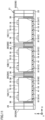
- Fig. 1 is a cross sectional view showing a battery pack according to an embodiment of the present invention.
- Fig. 2 is a perspective view showing a battery cell included in the battery pack in Fig. 1 .
- Fig. 3 is an exploded assembly diagram showing battery cells and a case body included in the battery pack in Fig. 1 .
- a battery pack 100 is used as a power supply for driving a vehicle such as a hybrid electric vehicle (HEV), a plug-in hybrid electric vehicle (PHEV), or a battery electric vehicle (BEV).
- a vehicle such as a hybrid electric vehicle (HEV), a plug-in hybrid electric vehicle (PHEV), or a battery electric vehicle (BEV).
- HEV hybrid electric vehicle
- PHEV plug-in hybrid electric vehicle
- BEV battery electric vehicle
- a "Y axis” represents an axis extending in a stacking direction of a plurality of below-described battery cells 11 and in a horizontal direction
- an "X axis” represents an axis extending in a direction orthogonal to the Y axis and in the horizontal direction
- a "Z axis” represents an axis extending in an upward/downward direction.
- Battery pack 100 has a plurality of battery cells 11 and a case body 21.
- the plurality of battery cells 11 are stacked in the Y axis direction.
- Case body 21 accommodates the plurality of battery cells 11.
- battery cell 11 is a lithium ion battery.
- Battery cell 11 has a prismatic shape and has a thin plate shape in the form of a rectangular parallelepiped.
- the plurality of battery cells 11 are stacked such that the Y axis direction corresponds to the thickness direction of each battery cell 11.
- Exterior package 12 is constituted of a housing having a rectangular parallelepiped shape, and forms an external appearance of battery cell 11. An electrode assembly and an electrolyte solution are accommodated in exterior package 12.
- Exterior package 12 has a first side surface 13, a second side surface 14, a top surface 15, and a bottom surface 16.
- Each of first side surface 13 and second side surface 14 is constituted of a flat surface orthogonal to the Y axis. First side surface 13 and second side surface 14 are oriented oppositely in the Y axis direction.
- Each of first side surface 13 and second side surface 14 has the largest area among the areas of the plurality of side surfaces of exterior package 12.
- Each of first side surface 13 and second side surface 14 has a rectangular shape.
- Each of first side surface 13 and second side surface 14 has a rectangular shape in which the X axis direction corresponds to the long side direction and the Z axis direction corresponds to the short side direction.
- top surface 15 and bottom surface 16 are constituted of a flat surface orthogonal to the Z axis. Top surface 15 is oriented upward. Bottom surface 16 is oriented downward. Top surface 15 is provided with a gas-discharge valve 17 for discharging gas generated in exterior package 12 to outside of exterior package 12 when internal pressure of exterior package 12 becomes equal to or more than a predetermined value due to the gas.
- Battery cell 11 further has electrode terminals 18 including a pair of a positive electrode terminal 18P and a negative electrode terminal 18N. Electrode terminal 18 is provided on top surface 15. Positive electrode terminal 18P and negative electrode terminal 18N are provided to be separated from each other in the X axis direction. Positive electrode terminal 18P and negative electrode terminal 18N are provided on both sides beside gas-discharge valve 17 in the X axis direction.
- the plurality of battery cells 11 are stacked such that first side surfaces 13 of battery cells 11, 11 adjacent to each other in the Y axis direction face each other and second side surfaces 14 of battery cells 11, 11 adjacent to each other in the Y axis direction face each other.
- positive electrode terminals 18P and negative electrode terminals 18N are alternately arranged in the Y axis direction in which the plurality of battery cells 11 are stacked.
- positive electrode terminal 18P and negative electrode terminal 18N arranged side by side in the Y axis direction are connected to each other by a bus bar (not shown).
- the plurality of battery cells 11 are electrically connected to one another in series.
- the plurality of battery cells 11 may be electrically connected to one another in parallel or in parallel and series in combination.
- the plurality of stacked battery cells 11 form a cell stack 10.
- Cell stack 10 has a rectangular parallelepiped shape.
- the length of cell stack 10 in the Y axis direction is larger than the length of cell stack 10 in the Z axis direction and is larger than the length of cell stack 10 in the X axis direction.
- Case body 21 is constituted of a box body having an external appearance with a rectangular parallelepiped shape.
- the length of case body 21 in the Y axis direction is larger than the length of case body 21 in the Z axis direction and is larger than the length of case body 21 in the X axis direction.
- Case body 21 has a case bottom portion 22, first case side portions 23 (23A, 23B), second case side portions 25 (25C, 25D), and a case top portion 24.
- case bottom portion 22 corresponds to a "first bottom portion” in the present invention
- each of first case side portions 23 corresponds to a "first side portion" in the present invention.
- Case bottom portion 22 is disposed at the bottom of case body 21.
- Case bottom portion 22 is composed of a plate material that has a thickness direction corresponding to the Z axis direction and that extends in the horizontal direction.
- Case bottom portion 22 is composed of a solid plate material.
- Case bottom portion 22 is not provided with a hollow portion.
- the plurality of battery cells 11 are placed on case bottom portion 22.
- the plurality of battery cells 11 are placed on case bottom portion 22 with a below-described heat conduction member 41 (bottom portion 42) being interposed therebetween.
- first case side portions 23 rises from case bottom portion 22 and extends upward.
- First case side portion 23 has a certain width in the X axis direction and extends in the Y axis direction.
- First case side portion 23 is provided along a peripheral edge of case bottom portion 22 extending in the Y axis direction.
- First case side portion 23A and first case side portion 23B are provided to be separated from each other in the X axis direction.
- Each of first case side portions 23 is composed of a frame material that defines and forms hollow portions 26.
- Each of hollow portions 26 extends in the Y axis direction, which is the stacking direction of the plurality of battery cells 11.
- first case side portion 23 When cut along an X-Z axes plane, first case side portion 23 has such a cross sectional shape that is unchanged among all the cutting positions in the Y axis direction.
- first case side portion 23 has a frame portion 27 and partition wall portions 28.
- frame portion 27 When cut along the X-Z axes plane, frame portion 27 has such a cross section that frame portion 27 extends along four sides of a rectangular shape.
- Frame portion 27 forms an external appearance of first case side portion 23.
- Partition wall portions 28 are provided inside frame portion 27.
- Partition wall portions 28 define a space inside frame portion 27 into the plurality of hollow portions 26.
- Each of hollow portions 26 has an opening having a rectangular shape when viewed in the Y axis direction.
- the plurality of hollow portions 26 are provided side by side in the X axis direction and the Z axis direction.
- first case side portion 23 is composed of an aluminum extrusion material.
- first case side portion 23 may be provided with a single hollow portion 26, or may be provided with a hollow portion 26 having a circular shape or a polygonal shape other than the rectangular shape.
- Second case side portions 25 rises from case bottom portion 22 and extends upward.
- Second case side portion 25 has a certain width in the Y axis direction and extends in the X axis direction.
- Second case side portion 25 is provided along a peripheral edge of case bottom portion 22 extending in the X axis direction.
- Second case side portion 25C and second case side portion 25D are provided to be separated from each other in the Y axis direction.
- Second case side portion 25C and second case side portion 25D are provided on both sides beside the plurality of battery cells 11 stacked in the Y axis direction. The plurality of battery cells 11 are restrained by second case side portion 25C and second case side portion 25D in the Y axis direction.
- First case side portions 23 and second case side portions 25 extend along the peripheral edges of case bottom portion 22.
- Space 70 is defined at a position located above case bottom portion 22 and surrounded by first case side portions 23 and second case side portions 25 so as to be open upward and accommodate the plurality of battery cells 11 (cell stack 10).
- Case top portion 24 is disposed to face case bottom portion 22 in the Z axis direction. Case top portion 24 is detachably attached to upper end portions of first case side portions 23 and second case side portions 25 and serves as a cover body to close the opening of space 70.
- Case bottom portion 22, first case side portions 23, second case side portions 25 and case top portion 24 are constituted of separate members, and are combined together to form case body 21.
- the case body of the present invention is not limited to such a configuration, and for example, the first case bottom portion and the first case side portions may be constituted of one member.
- a coolant path 31 is provided inside first case side portion 23 (23A, 23B). Coolant path 31 is provided inside frame portion 27 that forms the external appearance of first case side portion 23. Coolant path 31 allows coolant (for example, cooling water) to flow therethrough. Coolant path 31 allows the coolant to flow in the Y axis direction.
- coolant for example, cooling water
- Coolant path 31 is provided adjacent to the plurality of battery cells 11 (cell stack 10) in the X axis direction. Coolant path 31 extends between one end and the other end of the plurality of battery cells 11 in the Y axis direction.
- Battery pack 100 further has a tube member 32.
- Tube member 32 is disposed in a hollow portion 26.
- Tube member 32 is disposed in a hollow portion 26 positioned adjacent to battery cells 11 in the X axis direction and just above case bottom portion 22 in the Z axis direction among the plurality of hollow portions 26.
- Tube member 32 extends in the Y axis direction.
- Tube member 32 is provided in contact with the inner wall of first case side portion 23 that defines hollow portion 26.
- Coolant path 31 is constituted of tube member 32.
- Fig. 4 is a cross sectional view showing a battery pack according to a comparative example.
- a coolant path 131 is provided instead of coolant path 31 (tube member 32) in Fig. 1 .
- Coolant path 131 is provided inside case bottom portion 22.
- thickness t of case bottom portion 22 becomes large. This leads to a large overall height h of the battery pack, with the result that energy density with respect to the volume of the battery pack may be decreased and mountability of the battery pack onto a vehicle may be decreased.
- coolant path 31 (tube member 32) is provided inside first case side portion 23.
- thickness T of case bottom portion 22 can be small, overall height H of battery pack 100 can be small.
- Battery pack 100 further has heat conduction member 41.
- Heat conduction member 41 is interposed between each of battery cells 11 and case body 21. Heat conduction member 41 is interposed between each of the plurality of battery cells 11 (cell stack 10) and case body 21. Heat conduction member 41 is provided to extend between one end and the other end of the plurality of battery cells 11 (cell stack 10) in the Y axis direction.
- Heat conduction member 41 has a bottom portion 42 and side portions 43.
- bottom portion 42 corresponds to a "second bottom portion” in the present invention
- each of side portions 43 corresponds to a "second side portion” in the present invention.
- Bottom portion 42 is disposed between each of battery cells 11 (bottom surface 16) and case bottom portion 22.
- Each of side portions 43 is disposed between each of battery cells 11 and first case side portion 23 (23A, 23B).
- Bottom portion 42 is contiguous to a lower end portion 43q of side portion 43.
- An upper end portion 43p of side portion 43 is disposed above coolant path 31 (tube member 32). Upper end portion 43p of side portion 43 is disposed above a contact position of tube member 32 with first case side portion 23. Lower end portion 43q of side portion 43 is disposed below coolant path 31 (tube member 32).
- Heat conduction member 41 is composed of a material having a heat conductivity higher than that of air. Heat conduction member 41 is composed of, for example, a gap filler. Heat conduction member 41 has fluidity during assembling of battery pack 100, and is hardened when left at room temperature or when heated. Heat conduction member 41 is composed of a resin such as acrylic, urethane, or silicone. Heat conduction member 41 may be an adhesive agent that joins battery cells 11 to case body 21.
- heat conduction member 41 is an adhesive agent
- battery cell 11 can be fixed to case body 21 by using heat conduction member 41 for improving heat conduction from battery cell 11.
- Battery pack 100 further has protrusions 51.
- Protrusions 51 are disposed at corner portions of case bottom portion 22 and first case side portions 23 (23A, 23B). Protrusions 51 protrude toward battery cells 11. Each of protrusions 51 extends in the Y axis direction. Protrusion 51 has a rectangular shape when viewed in the Y axis direction.
- An upper end portion 51p of protrusion 51 is disposed above bottom surface 16 of battery cell 11.
- Upper end portion 51p of protrusion 51 is disposed below the contact position of tube member 32 with first case side portion 23.
- a lower end portion 51q of protrusion 51 is disposed below bottom surface 16 of battery cell 11.
- FIG. 5 and Fig. 6 are a cross sectional view showing a step during assembling of the battery pack in Fig. 1 .
- a heat conduction material 46 having flowablility is disposed in space 70.
- Heat conduction material 46 is disposed to have a certain height from case bottom portion 22.
- the plurality of battery cells 11 are disposed in space 70. By soaking the bottom portion of cell stack 10 in heat conduction material 46, heat conduction material 46 on case bottom portion 22 flows out to a space beside cell stack 10.
- heat conduction material 46 can be smoothly guided to the space beside cell stack 10 by protrusions 51 disposed at the corner portions of case bottom portion 22 and first case side portions 23. Further, since a clearance between each protrusion 51 and cell stack 10 in the X axis direction is small, an amount of flow of heat conduction material 46 toward the space beside cell stack 10 can be increased.
- heat conduction material 46 is hardened to form heat conduction member 41 having bottom portion 42 and side portions 43. It should be noted that with protrusions 51, a sealing characteristic between case bottom portion 22 and each of first case side portions 23 can be improved and the plurality of battery cells 11 can be more precisely aligned in the Y axis direction while ensuring a distance between each of first case side portions 23 and each of battery cells 11.
- FIG. 7 is a cross sectional view showing a first modification of the battery pack (coolant path) in Fig. 1 .
- tube member 32 in Fig. 1 is not provided in hollow portion 26, and hollow portion 26 constitutes coolant path 31 through which coolant flows. According to such a configuration, the number of components of the battery pack can be reduced.
- Figs. 8 to 10 are cross sectional views showing second to fourth modifications of the battery pack (protrusion) in Fig. 1 .
- Each of Figs. 8 to 10 shows a cross section of the battery pack corresponding to a range surrounded by a chain double-dashed line VIII in Fig. 1 .
- a side portion 51r of protrusion 51 facing battery cell 11 in the X axis direction is constituted of a tapered surface inclined with respect to the Z axis direction (upward/downward direction).
- the width of protrusion 51 in the X axis direction is smaller in a direction from lower end portion 51q toward upper end portion 51p.
- a chamfered portion 52 constituted of a flat surface is provided at a corner portion of side portion 51r and upper end portion 51p.
- a chamfered portion 53 constituted of a curved surface is provided at a corner portion of side portion 51r and upper end portion 51p.
- Fig. 11 is a cross sectional view showing a fifth modification of the battery pack in Fig. 1 .
- a plurality of cell stacks 10 (10A, 10B, 10C) are arranged side by side at intervals in the X axis direction orthogonal to the Y axis direction.
- Case body 21 further has first frames 29 (29A, 29B) and second frames 61 (61A, 61B, 61C, 61D, 61E, 61F).
- each of second frames 61 corresponds to the "first side portion" in the present invention.
- Each of first frames 29 has the same frame structure as that of first case side portion 23, and is provided on case bottom portion 22 to extend upward.
- First frame 29A extends in the Y axis direction in a space between cell stack 10A and cell stack 10B.
- First frame 29B extends in the Y axis direction in a space between cell stack 10B and cell stack 10C.
- Each of second frames 61 is composed of a frame material that rises from case bottom portion 22 and that extends in the Y axis direction.
- Second frame 61A is interposed between first case side portion 23A and cell stack 10A.
- Second frame 61B and second frame 61C rise from case bottom portion 22 toward the space between cell stack 10A and cell stack 10B.
- Second frame 61B is interposed between cell stack 10A and first frame 29A, and second frame 61C is interposed between first frame 29A and cell stack 10B.
- Second frame 61D and second frame 61E rise from case bottom portion 22 toward the space between cell stack 10B and cell stack 10C.
- Second frame 61D is interposed between cell stack 10B and first frame 29B
- second frame 61E is interposed between first frame 29B and cell stack 10C.
- Second frame 61F is interposed between cell stack 10C and first case side portion 23B.
- a coolant path 36 is provided inside each of second frames 61 (61A, 61B, 61C, 61D, 61E, 61F). Coolant path 36 extends in the Y axis direction. With such a configuration, battery cells 11 can be efficiently cooled in the plurality of cell stacks 10 while attaining a small overall height of the battery pack.
Landscapes
- Chemical & Material Sciences (AREA)
- Chemical Kinetics & Catalysis (AREA)
- Electrochemistry (AREA)
- General Chemical & Material Sciences (AREA)
- Engineering & Computer Science (AREA)
- Manufacturing & Machinery (AREA)
- Aviation & Aerospace Engineering (AREA)
- Secondary Cells (AREA)
- Battery Mounting, Suspending (AREA)
Abstract
Description
- This nonprovisional application is based on
Japanese Patent Application No. 2022-012847 filed on January 31, 2022 - The present invention relates to a battery pack.
- For example,
Japanese Patent Laying-Open No. 2013-25982 - Further,
Japanese Patent Laying-Open No. 2015-207541 - In the power supply device disclosed in
Japanese Patent Laying-Open No. 2013-25982 - Thus, it is an object of the present invention to solve the above-described problem and to provide a battery pack having a small overall height.
- A battery pack according to the present invention includes: a plurality of stacked battery cells; and a case body that has a first bottom portion and a first side portion and that accommodates the plurality of battery cells, the first bottom portion being a portion on which the plurality of battery cells are placed, the first side portion rising from the first bottom portion. A coolant path through which coolant flows is provided inside the first side portion.
- According to the battery pack thus configured, since the coolant path is provided in the first side portion, the thickness of the first bottom portion in the upward/downward direction can be small. Thus, an overall height of the battery pack can be small.
- Preferably, the battery pack further includes a heat conduction member interposed between each of the battery cells and the case body. The heat conduction member has a second side portion disposed between each of the battery cells and the first side portion.
- According to the battery pack thus configured, heat from each of the battery cells can be efficiently conducted, via the second side portion, to the first side portion provided with the coolant path. Thus, performance of cooling the battery cells can be improved.
- Preferably, an upper end portion of the second side portion is disposed above the coolant path. A lower end portion of the second side portion is disposed below the coolant path.
- According to the battery pack thus configured, since the second side portion is more securely disposed between each of the battery cells and the coolant path, heat from each of the battery cells can be more efficiently conducted to the first side portion via the second side portion.
- Preferably, the heat conduction member further has a second bottom portion contiguous to a lower end portion of the second side portion and disposed between each of the battery cells and the first bottom portion.
- According to the battery pack thus configured, heat from each of the battery cells can be efficiently conducted, via the second bottom portion and the first bottom portion, to the first side portion provided with the coolant path. Thus, the performance of cooling the battery cells can be further improved.
- Preferably, the battery pack further includes a protrusion that is disposed at a corner portion of the first bottom portion and the first side portion and that protrudes toward each of the battery cells.
- According to the battery pack thus configured, a clearance in which the heat conduction member is not disposed can be prevented from being formed at the corner portion of the first bottom portion and the first side portion.
- Preferably, the heat conduction member is composed of an adhesive agent that joins each of the battery cells to the case body. According to the battery pack thus configured, since the heat conduction member serves to conduct heat generated in each of the battery cells and join each of the battery cells to the case body, the battery pack can have a simple configuration.
- Preferably, the first bottom portion is composed of a solid plate material. According to the battery pack thus configured, the thickness of the first bottom portion in the upward/downward direction can be smaller.
- Preferably, the first side portion is composed of a frame material that extends in a stacking direction of the battery cells and that defines and forms a hollow portion. The hollow portion forms the coolant path.
- According to the battery pack thus configured, since the coolant flows directly through the hollow portion defined and formed by the first side portion, the battery pack can have a simple configuration.
- Preferably, the battery pack includes a plurality of cell stacks. Each of the cell stacks is constituted of the plurality of battery cells stacked in one direction. The plurality of cell stacks are arranged side by side at intervals in a direction orthogonal to the stacking direction of the battery cells. The first side portion rises from the first bottom portion toward a space between adjacent cell stacks of the plurality of cell stacks and extends in the stacking direction of the battery cells.
- According to the battery pack thus configured, the battery cells can be efficiently cooled in the plurality of cell stacks while attaining a small overall height of the battery pack.
- The foregoing and other objects, features, aspects and advantages of the present invention will become more apparent from the following detailed description of the present invention when taken in conjunction with the accompanying drawings.
-
-
Fig. 1 is a cross sectional view showing a battery pack according to an embodiment of the present invention. -
Fig. 2 is a perspective view showing a battery cell included in the battery pack inFig. 1 . -
Fig. 3 is an exploded assembly diagram showing battery cells and a case body included in the battery pack inFig. 1 . -
Fig. 4 is a cross sectional view showing a battery pack according to a comparative example. -
Fig. 5 is a cross sectional view showing a first step during assembling of the battery pack inFig. 1 . -
Fig. 6 is a cross sectional view showing a second step during assembling of the battery pack inFig. 1 . -
Fig. 7 is a cross sectional view showing a first modification of the battery pack (coolant path) inFig. 1 . -
Fig. 8 is a cross sectional view showing a second modification of the battery pack (protrusion) inFig. 1 . -
Fig. 9 is a cross sectional view showing a third modification of the battery pack (protrusion) inFig. 1 . -
Fig. 10 is a cross sectional view showing a fourth modification of the battery pack (protrusion) inFig. 1 . -
Fig. 11 is a cross sectional view showing a fifth modification of the battery pack inFig. 1 . - Embodiments of the present invention will be described with reference to figures. It should be noted that in the figures referred to below, the same or corresponding members are denoted by the same reference characters.
-
Fig. 1 is a cross sectional view showing a battery pack according to an embodiment of the present invention.Fig. 2 is a perspective view showing a battery cell included in the battery pack inFig. 1 .Fig. 3 is an exploded assembly diagram showing battery cells and a case body included in the battery pack inFig. 1 . - Referring to
Figs. 1 to 3 , abattery pack 100 is used as a power supply for driving a vehicle such as a hybrid electric vehicle (HEV), a plug-in hybrid electric vehicle (PHEV), or a battery electric vehicle (BEV). - In the present specification, for convenience of explanation of a structure of a
battery pack 100, a "Y axis" represents an axis extending in a stacking direction of a plurality of below-describedbattery cells 11 and in a horizontal direction, an "X axis" represents an axis extending in a direction orthogonal to the Y axis and in the horizontal direction, and a "Z axis" represents an axis extending in an upward/downward direction. -
Battery pack 100 has a plurality ofbattery cells 11 and acase body 21. The plurality ofbattery cells 11 are stacked in the Y axis direction.Case body 21 accommodates the plurality ofbattery cells 11. - As shown in
Fig. 2 ,battery cell 11 is a lithium ion battery.Battery cell 11 has a prismatic shape and has a thin plate shape in the form of a rectangular parallelepiped. The plurality ofbattery cells 11 are stacked such that the Y axis direction corresponds to the thickness direction of eachbattery cell 11. - Each of
battery cells 11 has anexterior package 12.Exterior package 12 is constituted of a housing having a rectangular parallelepiped shape, and forms an external appearance ofbattery cell 11. An electrode assembly and an electrolyte solution are accommodated inexterior package 12. -
Exterior package 12 has afirst side surface 13, asecond side surface 14, atop surface 15, and abottom surface 16. Each offirst side surface 13 andsecond side surface 14 is constituted of a flat surface orthogonal to the Y axis.First side surface 13 andsecond side surface 14 are oriented oppositely in the Y axis direction. Each offirst side surface 13 andsecond side surface 14 has the largest area among the areas of the plurality of side surfaces ofexterior package 12. Each offirst side surface 13 andsecond side surface 14 has a rectangular shape. Each offirst side surface 13 andsecond side surface 14 has a rectangular shape in which the X axis direction corresponds to the long side direction and the Z axis direction corresponds to the short side direction. - Each of
top surface 15 andbottom surface 16 is constituted of a flat surface orthogonal to the Z axis.Top surface 15 is oriented upward.Bottom surface 16 is oriented downward.Top surface 15 is provided with a gas-discharge valve 17 for discharging gas generated inexterior package 12 to outside ofexterior package 12 when internal pressure ofexterior package 12 becomes equal to or more than a predetermined value due to the gas. -
Battery cell 11 further haselectrode terminals 18 including a pair of apositive electrode terminal 18P and anegative electrode terminal 18N.Electrode terminal 18 is provided ontop surface 15.Positive electrode terminal 18P andnegative electrode terminal 18N are provided to be separated from each other in the X axis direction.Positive electrode terminal 18P andnegative electrode terminal 18N are provided on both sides beside gas-discharge valve 17 in the X axis direction. - The plurality of
battery cells 11 are stacked such that first side surfaces 13 ofbattery cells battery cells positive electrode terminals 18P andnegative electrode terminals 18N are alternately arranged in the Y axis direction in which the plurality ofbattery cells 11 are stacked. - Between
battery cells positive electrode terminal 18P andnegative electrode terminal 18N arranged side by side in the Y axis direction are connected to each other by a bus bar (not shown). The plurality ofbattery cells 11 are electrically connected to one another in series. The plurality ofbattery cells 11 may be electrically connected to one another in parallel or in parallel and series in combination. - The plurality of stacked
battery cells 11 form acell stack 10.Cell stack 10 has a rectangular parallelepiped shape. The length ofcell stack 10 in the Y axis direction is larger than the length ofcell stack 10 in the Z axis direction and is larger than the length ofcell stack 10 in the X axis direction. -
Case body 21 is constituted of a box body having an external appearance with a rectangular parallelepiped shape. The length ofcase body 21 in the Y axis direction is larger than the length ofcase body 21 in the Z axis direction and is larger than the length ofcase body 21 in the X axis direction.Case body 21 has a casebottom portion 22, first case side portions 23 (23A, 23B), second case side portions 25 (25C, 25D), and a casetop portion 24. In the present embodiment, casebottom portion 22 corresponds to a "first bottom portion" in the present invention, and each of firstcase side portions 23 corresponds to a "first side portion" in the present invention. -
Case bottom portion 22 is disposed at the bottom ofcase body 21.Case bottom portion 22 is composed of a plate material that has a thickness direction corresponding to the Z axis direction and that extends in the horizontal direction.Case bottom portion 22 is composed of a solid plate material.Case bottom portion 22 is not provided with a hollow portion. The plurality ofbattery cells 11 are placed on casebottom portion 22. The plurality ofbattery cells 11 are placed on casebottom portion 22 with a below-described heat conduction member 41 (bottom portion 42) being interposed therebetween. - Each of first
case side portions 23 rises from casebottom portion 22 and extends upward. Firstcase side portion 23 has a certain width in the X axis direction and extends in the Y axis direction. Firstcase side portion 23 is provided along a peripheral edge of casebottom portion 22 extending in the Y axis direction. Firstcase side portion 23A and firstcase side portion 23B are provided to be separated from each other in the X axis direction. - Each of first case side portions 23 (23A, 23B) is composed of a frame material that defines and forms
hollow portions 26. Each ofhollow portions 26 extends in the Y axis direction, which is the stacking direction of the plurality ofbattery cells 11. When cut along an X-Z axes plane, firstcase side portion 23 has such a cross sectional shape that is unchanged among all the cutting positions in the Y axis direction. - More specifically, first
case side portion 23 has aframe portion 27 andpartition wall portions 28. When cut along the X-Z axes plane,frame portion 27 has such a cross section thatframe portion 27 extends along four sides of a rectangular shape.Frame portion 27 forms an external appearance of firstcase side portion 23.Partition wall portions 28 are provided insideframe portion 27.Partition wall portions 28 define a space insideframe portion 27 into the plurality ofhollow portions 26. Each ofhollow portions 26 has an opening having a rectangular shape when viewed in the Y axis direction. The plurality ofhollow portions 26 are provided side by side in the X axis direction and the Z axis direction. As an example, firstcase side portion 23 is composed of an aluminum extrusion material. - It should be noted that first
case side portion 23 may be provided with a singlehollow portion 26, or may be provided with ahollow portion 26 having a circular shape or a polygonal shape other than the rectangular shape. - Each of second
case side portions 25 rises from casebottom portion 22 and extends upward. Secondcase side portion 25 has a certain width in the Y axis direction and extends in the X axis direction. Secondcase side portion 25 is provided along a peripheral edge of casebottom portion 22 extending in the X axis direction. Secondcase side portion 25C and secondcase side portion 25D are provided to be separated from each other in the Y axis direction. Secondcase side portion 25C and secondcase side portion 25D are provided on both sides beside the plurality ofbattery cells 11 stacked in the Y axis direction. The plurality ofbattery cells 11 are restrained by secondcase side portion 25C and secondcase side portion 25D in the Y axis direction. - First
case side portions 23 and secondcase side portions 25 extend along the peripheral edges of casebottom portion 22.Space 70 is defined at a position located above casebottom portion 22 and surrounded by firstcase side portions 23 and secondcase side portions 25 so as to be open upward and accommodate the plurality of battery cells 11 (cell stack 10). -
Case top portion 24 is disposed to face casebottom portion 22 in the Z axis direction.Case top portion 24 is detachably attached to upper end portions of firstcase side portions 23 and secondcase side portions 25 and serves as a cover body to close the opening ofspace 70. -
Case bottom portion 22, firstcase side portions 23, secondcase side portions 25 and casetop portion 24 are constituted of separate members, and are combined together to formcase body 21. The case body of the present invention is not limited to such a configuration, and for example, the first case bottom portion and the first case side portions may be constituted of one member. - A
coolant path 31 is provided inside first case side portion 23 (23A, 23B).Coolant path 31 is provided insideframe portion 27 that forms the external appearance of firstcase side portion 23.Coolant path 31 allows coolant (for example, cooling water) to flow therethrough.Coolant path 31 allows the coolant to flow in the Y axis direction. -
Coolant path 31 is provided adjacent to the plurality of battery cells 11 (cell stack 10) in the X axis direction.Coolant path 31 extends between one end and the other end of the plurality ofbattery cells 11 in the Y axis direction. -
Battery pack 100 further has atube member 32.Tube member 32 is disposed in ahollow portion 26.Tube member 32 is disposed in ahollow portion 26 positioned adjacent tobattery cells 11 in the X axis direction and just above casebottom portion 22 in the Z axis direction among the plurality ofhollow portions 26.Tube member 32 extends in the Y axis direction.Tube member 32 is provided in contact with the inner wall of firstcase side portion 23 that defineshollow portion 26.Coolant path 31 is constituted oftube member 32. -
Fig. 4 is a cross sectional view showing a battery pack according to a comparative example. Referring toFig. 4 , in the comparative example, acoolant path 131 is provided instead of coolant path 31 (tube member 32) inFig. 1 .Coolant path 131 is provided inside casebottom portion 22. In such a configuration, sincecoolant path 131 extends in casebottom portion 22, thickness t of casebottom portion 22 becomes large. This leads to a large overall height h of the battery pack, with the result that energy density with respect to the volume of the battery pack may be decreased and mountability of the battery pack onto a vehicle may be decreased. - Referring to
Figs. 1 to 3 , in contrast, inbattery pack 100 according to the present embodiment, coolant path 31 (tube member 32) is provided inside firstcase side portion 23. With such a configuration, since thickness T of casebottom portion 22 can be small, overall height H ofbattery pack 100 can be small. - The following continuously describes the structure of
battery pack 100.Battery pack 100 further hasheat conduction member 41. -
Heat conduction member 41 is interposed between each ofbattery cells 11 andcase body 21.Heat conduction member 41 is interposed between each of the plurality of battery cells 11 (cell stack 10) andcase body 21.Heat conduction member 41 is provided to extend between one end and the other end of the plurality of battery cells 11 (cell stack 10) in the Y axis direction. -
Heat conduction member 41 has abottom portion 42 andside portions 43. In the present embodiment,bottom portion 42 corresponds to a "second bottom portion" in the present invention, and each ofside portions 43 corresponds to a "second side portion" in the present invention.Bottom portion 42 is disposed between each of battery cells 11 (bottom surface 16) and casebottom portion 22. Each ofside portions 43 is disposed between each ofbattery cells 11 and first case side portion 23 (23A, 23B).Bottom portion 42 is contiguous to alower end portion 43q ofside portion 43. - An
upper end portion 43p ofside portion 43 is disposed above coolant path 31 (tube member 32).Upper end portion 43p ofside portion 43 is disposed above a contact position oftube member 32 with firstcase side portion 23.Lower end portion 43q ofside portion 43 is disposed below coolant path 31 (tube member 32). -
Heat conduction member 41 is composed of a material having a heat conductivity higher than that of air.Heat conduction member 41 is composed of, for example, a gap filler.Heat conduction member 41 has fluidity during assembling ofbattery pack 100, and is hardened when left at room temperature or when heated.Heat conduction member 41 is composed of a resin such as acrylic, urethane, or silicone.Heat conduction member 41 may be an adhesive agent that joinsbattery cells 11 tocase body 21. - According to such a configuration, since
side portion 43 ofheat conduction member 41 is disposed betweenbattery cell 11 and firstcase side portion 23, heat frombattery cell 11, which emits heat, can be efficiently conducted throughside portion 43 to firstcase side portion 23 including coolant path 31 (tube member 32). Thus, performance of coolingbattery cells 11 can be improved. In this case, sinceupper end portion 43p ofside portion 43 is disposed abovecoolant path 31 andlower end portion 43q ofside portion 43 is disposed belowcoolant path 31,side portion 43 can be disposed more securely on a path of conduction of heat frombattery cell 11 tocoolant path 31. Further, sinceheat conduction member 41 hasbottom portion 42 disposed betweenbattery cell 11 and casebottom portion 22, heat frombattery cell 11 can be conducted to firstcase side portion 23 throughbottom portion 42 and casebottom portion 22. Thus, the performance of coolingbattery cells 11 can be further improved. - When
heat conduction member 41 is an adhesive agent,battery cell 11 can be fixed tocase body 21 by usingheat conduction member 41 for improving heat conduction frombattery cell 11. -
Battery pack 100 further hasprotrusions 51.Protrusions 51 are disposed at corner portions of casebottom portion 22 and first case side portions 23 (23A, 23B).Protrusions 51 protrude towardbattery cells 11. Each ofprotrusions 51 extends in the Y axis direction.Protrusion 51 has a rectangular shape when viewed in the Y axis direction. Anupper end portion 51p ofprotrusion 51 is disposed abovebottom surface 16 ofbattery cell 11.Upper end portion 51p ofprotrusion 51 is disposed below the contact position oftube member 32 with firstcase side portion 23. Alower end portion 51q ofprotrusion 51 is disposed belowbottom surface 16 ofbattery cell 11. - Each of
Fig. 5 andFig. 6 is a cross sectional view showing a step during assembling of the battery pack inFig. 1 . Referring toFig. 5 , aheat conduction material 46 having flowablility is disposed inspace 70.Heat conduction material 46 is disposed to have a certain height from casebottom portion 22. Referring toFig. 6 , next, the plurality of battery cells 11 (cell stack 10) are disposed inspace 70. By soaking the bottom portion ofcell stack 10 inheat conduction material 46,heat conduction material 46 on casebottom portion 22 flows out to a space besidecell stack 10. On this occasion,heat conduction material 46 can be smoothly guided to the space besidecell stack 10 byprotrusions 51 disposed at the corner portions of casebottom portion 22 and firstcase side portions 23. Further, since a clearance between eachprotrusion 51 andcell stack 10 in the X axis direction is small, an amount of flow ofheat conduction material 46 toward the space besidecell stack 10 can be increased. - Then,
heat conduction material 46 is hardened to formheat conduction member 41 havingbottom portion 42 andside portions 43. It should be noted that withprotrusions 51, a sealing characteristic between casebottom portion 22 and each of firstcase side portions 23 can be improved and the plurality ofbattery cells 11 can be more precisely aligned in the Y axis direction while ensuring a distance between each of firstcase side portions 23 and each ofbattery cells 11. - Next, various modifications of
battery pack 100 will be described.Fig. 7 is a cross sectional view showing a first modification of the battery pack (coolant path) inFig. 1 . Referring toFig. 7 , in the present modification,tube member 32 inFig. 1 is not provided inhollow portion 26, andhollow portion 26 constitutescoolant path 31 through which coolant flows. According to such a configuration, the number of components of the battery pack can be reduced. -
Figs. 8 to 10 are cross sectional views showing second to fourth modifications of the battery pack (protrusion) inFig. 1 . Each ofFigs. 8 to 10 shows a cross section of the battery pack corresponding to a range surrounded by a chain double-dashed line VIII inFig. 1 . - Referring to
Fig. 8 , in the present modification, aside portion 51r ofprotrusion 51 facingbattery cell 11 in the X axis direction is constituted of a tapered surface inclined with respect to the Z axis direction (upward/downward direction). The width ofprotrusion 51 in the X axis direction is smaller in a direction fromlower end portion 51q towardupper end portion 51p. Referring toFig. 9 , in the present modification, a chamferedportion 52 constituted of a flat surface is provided at a corner portion ofside portion 51r andupper end portion 51p. Referring toFig. 10 , in the present modification, a chamferedportion 53 constituted of a curved surface is provided at a corner portion ofside portion 51r andupper end portion 51p. - According to these modifications, during the step of disposing the plurality of battery cells 11 (cell stack 10) in
space 70,cell stack 10 is smoothly guided byprotrusions 51 to a position just above casebottom portion 22. Therefore, the step of disposing the plurality ofbattery cells 11 inspace 70 can be performed readily. Further, by providing each ofchamfered portions Figs. 9 and10 inprotrusion 51, each of battery cells 11 (particularly, an insulating sheet material that coversexterior package 12 of battery cell 11) can be suppressed from being broken due to contact withprotrusion 51. -
Fig. 11 is a cross sectional view showing a fifth modification of the battery pack inFig. 1 . Referring toFig. 11 , in the present modification, a plurality of cell stacks 10 (10A, 10B, 10C) are arranged side by side at intervals in the X axis direction orthogonal to the Y axis direction.Case body 21 further has first frames 29 (29A, 29B) and second frames 61 (61A, 61B, 61C, 61D, 61E, 61F). In the present modification, each ofsecond frames 61 corresponds to the "first side portion" in the present invention. - Each of
first frames 29 has the same frame structure as that of firstcase side portion 23, and is provided on casebottom portion 22 to extend upward.First frame 29A extends in the Y axis direction in a space betweencell stack 10A andcell stack 10B.First frame 29B extends in the Y axis direction in a space betweencell stack 10B andcell stack 10C. - Each of
second frames 61 is composed of a frame material that rises from casebottom portion 22 and that extends in the Y axis direction.Second frame 61A is interposed between firstcase side portion 23A and cell stack 10A.Second frame 61B andsecond frame 61C rise from casebottom portion 22 toward the space betweencell stack 10A andcell stack 10B.Second frame 61B is interposed betweencell stack 10A andfirst frame 29A, andsecond frame 61C is interposed betweenfirst frame 29A andcell stack 10B.Second frame 61D andsecond frame 61E rise from casebottom portion 22 toward the space betweencell stack 10B andcell stack 10C.Second frame 61D is interposed betweencell stack 10B andfirst frame 29B, andsecond frame 61E is interposed betweenfirst frame 29B andcell stack 10C.Second frame 61F is interposed betweencell stack 10C and firstcase side portion 23B. - A
coolant path 36 is provided inside each of second frames 61 (61A, 61B, 61C, 61D, 61E, 61F).Coolant path 36 extends in the Y axis direction. With such a configuration,battery cells 11 can be efficiently cooled in the plurality of cell stacks 10 while attaining a small overall height of the battery pack. - Although the embodiments of the present invention have been described and illustrated in detail, it is clearly understood that the same is by way of illustration and example only and is not to be taken by way of limitation, the scope of the present invention being interpreted by the terms of the appended claims. The scope of the present invention is defined by the terms of the claims, and is intended to include any modifications within the scope and meaning equivalent to the terms of the claims.
Claims (9)
- A battery pack comprising:a plurality of stacked battery cells (11); anda case body (21) that has a first bottom portion (22) and a first side portion (23) and that accommodates the plurality of battery cells (11), the first bottom portion (22) being a portion on which the plurality of battery cells (11) are placed, the first side portion (23) rising from the first bottom portion (22), whereina coolant path (31) through which coolant flows is provided inside the first side portion (23).
- The battery pack according to claim 1, further comprising a heat conduction member (41) interposed between each of the battery cells (11) and the case body (21), wherein
the heat conduction member (41) has a second side portion (43) disposed between each of the battery cells (11) and the first side portion (23). - The battery pack according to claim 2, whereinan upper end portion (43p) of the second side portion (43) is disposed above the coolant path (31), anda lower end portion (43q) of the second side portion (43) is disposed below the coolant path (31).
- The battery pack according to claim 2 or 3, wherein the heat conduction member (41) further has a second bottom portion (42) contiguous to a lower end portion (43q) of the second side portion (43) and disposed between each of the battery cells (11) and the first bottom portion (22).
- The battery pack according to claim 4, further comprising a protrusion (51) that is disposed at a corner portion of the first bottom portion (22) and the first side portion (23) and that protrudes toward each of the battery cells (11).
- The battery pack according to claim 2, wherein the heat conduction member (41) is composed of an adhesive agent that joins each of the battery cells (11) to the case body (21).
- The battery pack according to any one of claims 1 to 6, wherein the first bottom portion (22) is composed of a solid plate material.
- The battery pack according to any one of claims 1 to 7, whereinthe first side portion (23) is composed of a frame material that extends in a stacking direction of the battery cells (11) and that defines and forms a hollow portion (26), andthe hollow portion (26) forms the coolant path (31).
- The battery pack according to any one of claims 1 to 8, comprising a plurality of cell stacks (10), whereineach of the cell stacks (10) is constituted of the plurality of battery cells (11) stacked in one direction,the plurality of cell stacks (10) are arranged side by side at intervals in a direction orthogonal to the stacking direction of the battery cells (11), andthe first side portion (23) rises from the first bottom portion (22) toward a space between adjacent cell stacks (10) of the plurality of cell stacks (10) and extends in the stacking direction of the battery cells (11).
Applications Claiming Priority (1)
| Application Number | Priority Date | Filing Date | Title |
|---|---|---|---|
| JP2022012847A JP7513644B2 (en) | 2022-01-31 | 2022-01-31 | Battery pack |
Publications (2)
| Publication Number | Publication Date |
|---|---|
| EP4220834A1 true EP4220834A1 (en) | 2023-08-02 |
| EP4220834B1 EP4220834B1 (en) | 2025-06-18 |
Family
ID=84568795
Family Applications (1)
| Application Number | Title | Priority Date | Filing Date |
|---|---|---|---|
| EP22215659.8A Active EP4220834B1 (en) | 2022-01-31 | 2022-12-21 | Battery pack |
Country Status (5)
| Country | Link |
|---|---|
| US (1) | US12476303B2 (en) |
| EP (1) | EP4220834B1 (en) |
| JP (1) | JP7513644B2 (en) |
| KR (1) | KR102880589B1 (en) |
| CN (1) | CN116525999A (en) |
Citations (8)
| Publication number | Priority date | Publication date | Assignee | Title |
|---|---|---|---|---|
| JP2013025982A (en) | 2011-07-20 | 2013-02-04 | Sanyo Electric Co Ltd | Power supply device and vehicle with power supply device |
| JP2015207541A (en) | 2014-04-23 | 2015-11-19 | 日立建機株式会社 | Work machine and cooling structure of power storage device mounted to the same |
| EP2851991B1 (en) * | 2012-05-17 | 2018-11-21 | Hitachi Automotive Systems, Ltd. | Battery module |
| DE102017005315A1 (en) * | 2017-06-02 | 2018-12-06 | Audi Ag | battery box |
| WO2019221394A1 (en) * | 2018-05-15 | 2019-11-21 | 삼성에스디아이주식회사 | Battery pack |
| US20200036062A1 (en) * | 2018-07-27 | 2020-01-30 | Mahle International Gmbh | Accumulator arrangement |
| US20210218082A1 (en) * | 2018-09-26 | 2021-07-15 | Vehicle Energy Japan Inc. | Battery pack |
| JP2022012847A (en) | 2020-07-02 | 2022-01-17 | オムロン株式会社 | Electromagnetic relay |
Family Cites Families (9)
| Publication number | Priority date | Publication date | Assignee | Title |
|---|---|---|---|---|
| DE102012221503B4 (en) * | 2012-11-23 | 2022-01-05 | Vitesco Technologies GmbH | Energy storage device with a multiplicity of energy storage cells and with a housing as well as a method for producing an energy storage device |
| WO2014155609A1 (en) | 2013-03-28 | 2014-10-02 | 日立オートモティブシステムズ株式会社 | Battery module |
| US9509018B2 (en) * | 2014-01-16 | 2016-11-29 | Ford Global Technologies, Llc | Expanded battery cooling fin |
| KR20180048030A (en) * | 2016-11-02 | 2018-05-10 | 삼성에스디아이 주식회사 | Rechargeable battery and module thereof |
| SE541552C2 (en) * | 2017-12-21 | 2019-10-29 | Scania Cv Ab | An arrangement for cooling of electrical energy storage units |
| KR102389911B1 (en) * | 2018-09-17 | 2022-04-21 | 주식회사 엘지에너지솔루션 | Battery Module Having Module Housing |
| CN111384464B (en) * | 2018-12-29 | 2024-09-10 | 宁德时代新能源科技股份有限公司 | Battery modules and battery packs |
| JP7048545B2 (en) | 2019-07-24 | 2022-04-05 | 本田技研工業株式会社 | Cell fixing mechanism, battery pack and cell fixing method |
| KR20210150843A (en) * | 2020-06-04 | 2021-12-13 | 주식회사 엘지에너지솔루션 | Battery module and battery pack including the same |
-
2022
- 2022-01-31 JP JP2022012847A patent/JP7513644B2/en active Active
- 2022-12-21 EP EP22215659.8A patent/EP4220834B1/en active Active
- 2022-12-28 US US18/147,175 patent/US12476303B2/en active Active
-
2023
- 2023-01-20 KR KR1020230008705A patent/KR102880589B1/en active Active
- 2023-01-28 CN CN202310051930.9A patent/CN116525999A/en active Pending
Patent Citations (8)
| Publication number | Priority date | Publication date | Assignee | Title |
|---|---|---|---|---|
| JP2013025982A (en) | 2011-07-20 | 2013-02-04 | Sanyo Electric Co Ltd | Power supply device and vehicle with power supply device |
| EP2851991B1 (en) * | 2012-05-17 | 2018-11-21 | Hitachi Automotive Systems, Ltd. | Battery module |
| JP2015207541A (en) | 2014-04-23 | 2015-11-19 | 日立建機株式会社 | Work machine and cooling structure of power storage device mounted to the same |
| DE102017005315A1 (en) * | 2017-06-02 | 2018-12-06 | Audi Ag | battery box |
| WO2019221394A1 (en) * | 2018-05-15 | 2019-11-21 | 삼성에스디아이주식회사 | Battery pack |
| US20200036062A1 (en) * | 2018-07-27 | 2020-01-30 | Mahle International Gmbh | Accumulator arrangement |
| US20210218082A1 (en) * | 2018-09-26 | 2021-07-15 | Vehicle Energy Japan Inc. | Battery pack |
| JP2022012847A (en) | 2020-07-02 | 2022-01-17 | オムロン株式会社 | Electromagnetic relay |
Also Published As
| Publication number | Publication date |
|---|---|
| US12476303B2 (en) | 2025-11-18 |
| JP2023111154A (en) | 2023-08-10 |
| EP4220834B1 (en) | 2025-06-18 |
| CN116525999A (en) | 2023-08-01 |
| KR102880589B1 (en) | 2025-11-05 |
| US20230246265A1 (en) | 2023-08-03 |
| JP7513644B2 (en) | 2024-07-09 |
| KR20230117521A (en) | 2023-08-08 |
Similar Documents
| Publication | Publication Date | Title |
|---|---|---|
| KR101307992B1 (en) | Battery module with cooling structure of high efficiency | |
| KR100876458B1 (en) | Battery cartridge of novel structure and open battery module containing it | |
| KR101547814B1 (en) | Battery Module Having Indirect Air-Cooling Structure | |
| JP4757508B2 (en) | Electrical device assembly | |
| EP3244478A1 (en) | Submodule and battery module having the same | |
| JP7633393B2 (en) | Battery module and battery pack including same | |
| KR20160040799A (en) | A Battery Pack Case Having Efficient Cooling Structure | |
| KR101609232B1 (en) | Battery Module Comprising Cartridge Having Coolant Flow Channel | |
| KR20210133537A (en) | Battery pack and device including the same | |
| CN115039280B (en) | Battery pack and device including the battery pack | |
| US20230238639A1 (en) | Battery pack | |
| KR102026386B1 (en) | Battery module | |
| KR20140142770A (en) | Middle or Large-sized Battery Pack Having Efficient Cooling Structure | |
| KR102635431B1 (en) | Cartridge for battery cell and Battery module having the same | |
| CN120712684A (en) | Battery cells, batteries and electrical devices | |
| JP7580841B2 (en) | Battery module and battery pack including same | |
| JP2023529736A (en) | Battery packs and devices containing them | |
| KR102683482B1 (en) | Battery Pack | |
| KR101561121B1 (en) | Middle or Large-sized Battery Pack Having Efficient Cooling Structure | |
| EP4220834B1 (en) | Battery pack | |
| CN219759856U (en) | Battery case and lithium battery module | |
| JP2025518854A (en) | Battery pack and device including same | |
| KR102951911B1 (en) | Battery pack and vehicle including the same | |
| EP4398395A1 (en) | Battery pack and device including same | |
| KR20230170578A (en) | Battery pack and device including the same |
Legal Events
| Date | Code | Title | Description |
|---|---|---|---|
| PUAI | Public reference made under article 153(3) epc to a published international application that has entered the european phase |
Free format text: ORIGINAL CODE: 0009012 |
|
| STAA | Information on the status of an ep patent application or granted ep patent |
Free format text: STATUS: REQUEST FOR EXAMINATION WAS MADE |
|
| 17P | Request for examination filed |
Effective date: 20221221 |
|
| AK | Designated contracting states |
Kind code of ref document: A1 Designated state(s): AL AT BE BG CH CY CZ DE DK EE ES FI FR GB GR HR HU IE IS IT LI LT LU LV MC ME MK MT NL NO PL PT RO RS SE SI SK SM TR |
|
| STAA | Information on the status of an ep patent application or granted ep patent |
Free format text: STATUS: EXAMINATION IS IN PROGRESS |
|
| 17Q | First examination report despatched |
Effective date: 20240828 |
|
| GRAP | Despatch of communication of intention to grant a patent |
Free format text: ORIGINAL CODE: EPIDOSNIGR1 |
|
| STAA | Information on the status of an ep patent application or granted ep patent |
Free format text: STATUS: GRANT OF PATENT IS INTENDED |
|
| INTG | Intention to grant announced |
Effective date: 20250401 |
|
| RIN1 | Information on inventor provided before grant (corrected) |
Inventor name: YOSHIDA, NAOTAKE Inventor name: HONDA, RYOHEI Inventor name: MATSUYAMA, SATORU |
|
| GRAS | Grant fee paid |
Free format text: ORIGINAL CODE: EPIDOSNIGR3 |
|
| GRAA | (expected) grant |
Free format text: ORIGINAL CODE: 0009210 |
|
| STAA | Information on the status of an ep patent application or granted ep patent |
Free format text: STATUS: THE PATENT HAS BEEN GRANTED |
|
| P01 | Opt-out of the competence of the unified patent court (upc) registered |
Free format text: CASE NUMBER: APP_18885/2025 Effective date: 20250417 |
|
| AK | Designated contracting states |
Kind code of ref document: B1 Designated state(s): AL AT BE BG CH CY CZ DE DK EE ES FI FR GB GR HR HU IE IS IT LI LT LU LV MC ME MK MT NL NO PL PT RO RS SE SI SK SM TR |
|
| REG | Reference to a national code |
Ref country code: GB Ref legal event code: FG4D |
|
| REG | Reference to a national code |
Ref country code: CH Ref legal event code: EP |
|
| REG | Reference to a national code |
Ref country code: DE Ref legal event code: R096 Ref document number: 602022016065 Country of ref document: DE |
|
| REG | Reference to a national code |
Ref country code: CH Ref legal event code: EP |
|
| REG | Reference to a national code |
Ref country code: IE Ref legal event code: FG4D |
|
| PG25 | Lapsed in a contracting state [announced via postgrant information from national office to epo] |
Ref country code: FI Free format text: LAPSE BECAUSE OF FAILURE TO SUBMIT A TRANSLATION OF THE DESCRIPTION OR TO PAY THE FEE WITHIN THE PRESCRIBED TIME-LIMIT Effective date: 20250618 |
|
| REG | Reference to a national code |
Ref country code: LT Ref legal event code: MG9D |
|
| PG25 | Lapsed in a contracting state [announced via postgrant information from national office to epo] |
Ref country code: GR Free format text: LAPSE BECAUSE OF FAILURE TO SUBMIT A TRANSLATION OF THE DESCRIPTION OR TO PAY THE FEE WITHIN THE PRESCRIBED TIME-LIMIT Effective date: 20250919 Ref country code: NO Free format text: LAPSE BECAUSE OF FAILURE TO SUBMIT A TRANSLATION OF THE DESCRIPTION OR TO PAY THE FEE WITHIN THE PRESCRIBED TIME-LIMIT Effective date: 20250918 |
|
| PG25 | Lapsed in a contracting state [announced via postgrant information from national office to epo] |
Ref country code: BG Free format text: LAPSE BECAUSE OF FAILURE TO SUBMIT A TRANSLATION OF THE DESCRIPTION OR TO PAY THE FEE WITHIN THE PRESCRIBED TIME-LIMIT Effective date: 20250618 |
|
| PG25 | Lapsed in a contracting state [announced via postgrant information from national office to epo] |
Ref country code: HR Free format text: LAPSE BECAUSE OF FAILURE TO SUBMIT A TRANSLATION OF THE DESCRIPTION OR TO PAY THE FEE WITHIN THE PRESCRIBED TIME-LIMIT Effective date: 20250618 |
|
| PG25 | Lapsed in a contracting state [announced via postgrant information from national office to epo] |
Ref country code: RS Free format text: LAPSE BECAUSE OF FAILURE TO SUBMIT A TRANSLATION OF THE DESCRIPTION OR TO PAY THE FEE WITHIN THE PRESCRIBED TIME-LIMIT Effective date: 20250918 |
|
| REG | Reference to a national code |
Ref country code: NL Ref legal event code: MP Effective date: 20250618 |
|
| PG25 | Lapsed in a contracting state [announced via postgrant information from national office to epo] |
Ref country code: LV Free format text: LAPSE BECAUSE OF FAILURE TO SUBMIT A TRANSLATION OF THE DESCRIPTION OR TO PAY THE FEE WITHIN THE PRESCRIBED TIME-LIMIT Effective date: 20250618 |
|
| PG25 | Lapsed in a contracting state [announced via postgrant information from national office to epo] |
Ref country code: NL Free format text: LAPSE BECAUSE OF FAILURE TO SUBMIT A TRANSLATION OF THE DESCRIPTION OR TO PAY THE FEE WITHIN THE PRESCRIBED TIME-LIMIT Effective date: 20250618 |
|
| PG25 | Lapsed in a contracting state [announced via postgrant information from national office to epo] |
Ref country code: PT Free format text: LAPSE BECAUSE OF FAILURE TO SUBMIT A TRANSLATION OF THE DESCRIPTION OR TO PAY THE FEE WITHIN THE PRESCRIBED TIME-LIMIT Effective date: 20251020 |
|
| REG | Reference to a national code |
Ref country code: AT Ref legal event code: MK05 Ref document number: 1805093 Country of ref document: AT Kind code of ref document: T Effective date: 20250618 |
|
| PG25 | Lapsed in a contracting state [announced via postgrant information from national office to epo] |
Ref country code: IS Free format text: LAPSE BECAUSE OF FAILURE TO SUBMIT A TRANSLATION OF THE DESCRIPTION OR TO PAY THE FEE WITHIN THE PRESCRIBED TIME-LIMIT Effective date: 20251018 |
|
| PGFP | Annual fee paid to national office [announced via postgrant information from national office to epo] |
Ref country code: DE Payment date: 20251030 Year of fee payment: 4 |
|
| PG25 | Lapsed in a contracting state [announced via postgrant information from national office to epo] |
Ref country code: AT Free format text: LAPSE BECAUSE OF FAILURE TO SUBMIT A TRANSLATION OF THE DESCRIPTION OR TO PAY THE FEE WITHIN THE PRESCRIBED TIME-LIMIT Effective date: 20250618 Ref country code: SM Free format text: LAPSE BECAUSE OF FAILURE TO SUBMIT A TRANSLATION OF THE DESCRIPTION OR TO PAY THE FEE WITHIN THE PRESCRIBED TIME-LIMIT Effective date: 20250618 |
|
| PGFP | Annual fee paid to national office [announced via postgrant information from national office to epo] |
Ref country code: FR Payment date: 20251103 Year of fee payment: 4 |
|
| PG25 | Lapsed in a contracting state [announced via postgrant information from national office to epo] |
Ref country code: CZ Free format text: LAPSE BECAUSE OF FAILURE TO SUBMIT A TRANSLATION OF THE DESCRIPTION OR TO PAY THE FEE WITHIN THE PRESCRIBED TIME-LIMIT Effective date: 20250618 |
|
| PG25 | Lapsed in a contracting state [announced via postgrant information from national office to epo] |
Ref country code: PL Free format text: LAPSE BECAUSE OF FAILURE TO SUBMIT A TRANSLATION OF THE DESCRIPTION OR TO PAY THE FEE WITHIN THE PRESCRIBED TIME-LIMIT Effective date: 20250618 |
|
| PG25 | Lapsed in a contracting state [announced via postgrant information from national office to epo] |
Ref country code: EE Free format text: LAPSE BECAUSE OF FAILURE TO SUBMIT A TRANSLATION OF THE DESCRIPTION OR TO PAY THE FEE WITHIN THE PRESCRIBED TIME-LIMIT Effective date: 20250618 |
|
| PG25 | Lapsed in a contracting state [announced via postgrant information from national office to epo] |
Ref country code: SK Free format text: LAPSE BECAUSE OF FAILURE TO SUBMIT A TRANSLATION OF THE DESCRIPTION OR TO PAY THE FEE WITHIN THE PRESCRIBED TIME-LIMIT Effective date: 20250618 |
|
| PG25 | Lapsed in a contracting state [announced via postgrant information from national office to epo] |
Ref country code: ES Free format text: LAPSE BECAUSE OF FAILURE TO SUBMIT A TRANSLATION OF THE DESCRIPTION OR TO PAY THE FEE WITHIN THE PRESCRIBED TIME-LIMIT Effective date: 20250618 |
|
| PG25 | Lapsed in a contracting state [announced via postgrant information from national office to epo] |
Ref country code: RO Free format text: LAPSE BECAUSE OF FAILURE TO SUBMIT A TRANSLATION OF THE DESCRIPTION OR TO PAY THE FEE WITHIN THE PRESCRIBED TIME-LIMIT Effective date: 20250618 |
|
| REG | Reference to a national code |
Ref country code: DE Ref legal event code: R097 Ref document number: 602022016065 Country of ref document: DE |
|
| PG25 | Lapsed in a contracting state [announced via postgrant information from national office to epo] |
Ref country code: DK Free format text: LAPSE BECAUSE OF FAILURE TO SUBMIT A TRANSLATION OF THE DESCRIPTION OR TO PAY THE FEE WITHIN THE PRESCRIBED TIME-LIMIT Effective date: 20250618 |
|
| PG25 | Lapsed in a contracting state [announced via postgrant information from national office to epo] |
Ref country code: IT Free format text: LAPSE BECAUSE OF FAILURE TO SUBMIT A TRANSLATION OF THE DESCRIPTION OR TO PAY THE FEE WITHIN THE PRESCRIBED TIME-LIMIT Effective date: 20250618 |
|
| PLBE | No opposition filed within time limit |
Free format text: ORIGINAL CODE: 0009261 |
|
| STAA | Information on the status of an ep patent application or granted ep patent |
Free format text: STATUS: NO OPPOSITION FILED WITHIN TIME LIMIT |
|
| REG | Reference to a national code |
Ref country code: CH Ref legal event code: L10 Free format text: ST27 STATUS EVENT CODE: U-0-0-L10-L00 (AS PROVIDED BY THE NATIONAL OFFICE) Effective date: 20260430 |