EP4220813A1 - Battery module inspection device capable of adjusting location of connection part - Google Patents
Battery module inspection device capable of adjusting location of connection part Download PDFInfo
- Publication number
- EP4220813A1 EP4220813A1 EP22861728.8A EP22861728A EP4220813A1 EP 4220813 A1 EP4220813 A1 EP 4220813A1 EP 22861728 A EP22861728 A EP 22861728A EP 4220813 A1 EP4220813 A1 EP 4220813A1
- Authority
- EP
- European Patent Office
- Prior art keywords
- battery module
- coupling portion
- stage
- inspection apparatus
- guide portions
- Prior art date
- Legal status (The legal status is an assumption and is not a legal conclusion. Google has not performed a legal analysis and makes no representation as to the accuracy of the status listed.)
- Pending
Links
Images





Classifications
-
- G—PHYSICS
- G01—MEASURING; TESTING
- G01R—MEASURING ELECTRIC VARIABLES; MEASURING MAGNETIC VARIABLES
- G01R31/00—Arrangements for testing electric properties; Arrangements for locating electric faults; Arrangements for electrical testing characterised by what is being tested not provided for elsewhere
- G01R31/36—Arrangements for testing, measuring or monitoring the electrical condition of accumulators or electric batteries, e.g. capacity or state of charge [SoC]
-
- H—ELECTRICITY
- H01—ELECTRIC ELEMENTS
- H01M—PROCESSES OR MEANS, e.g. BATTERIES, FOR THE DIRECT CONVERSION OF CHEMICAL ENERGY INTO ELECTRICAL ENERGY
- H01M10/00—Secondary cells; Manufacture thereof
- H01M10/42—Methods or arrangements for servicing or maintenance of secondary cells or secondary half-cells
- H01M10/4285—Testing apparatus
-
- G—PHYSICS
- G01—MEASURING; TESTING
- G01R—MEASURING ELECTRIC VARIABLES; MEASURING MAGNETIC VARIABLES
- G01R31/00—Arrangements for testing electric properties; Arrangements for locating electric faults; Arrangements for electrical testing characterised by what is being tested not provided for elsewhere
- G01R31/36—Arrangements for testing, measuring or monitoring the electrical condition of accumulators or electric batteries, e.g. capacity or state of charge [SoC]
- G01R31/3644—Constructional arrangements
-
- G—PHYSICS
- G01—MEASURING; TESTING
- G01R—MEASURING ELECTRIC VARIABLES; MEASURING MAGNETIC VARIABLES
- G01R31/00—Arrangements for testing electric properties; Arrangements for locating electric faults; Arrangements for electrical testing characterised by what is being tested not provided for elsewhere
- G01R31/36—Arrangements for testing, measuring or monitoring the electrical condition of accumulators or electric batteries, e.g. capacity or state of charge [SoC]
- G01R31/364—Battery terminal connectors with integrated measuring arrangements
-
- G—PHYSICS
- G01—MEASURING; TESTING
- G01R—MEASURING ELECTRIC VARIABLES; MEASURING MAGNETIC VARIABLES
- G01R31/00—Arrangements for testing electric properties; Arrangements for locating electric faults; Arrangements for electrical testing characterised by what is being tested not provided for elsewhere
- G01R31/36—Arrangements for testing, measuring or monitoring the electrical condition of accumulators or electric batteries, e.g. capacity or state of charge [SoC]
- G01R31/385—Arrangements for measuring battery or accumulator variables
- G01R31/3865—Arrangements for measuring battery or accumulator variables related to manufacture, e.g. testing after manufacture
-
- H—ELECTRICITY
- H01—ELECTRIC ELEMENTS
- H01M—PROCESSES OR MEANS, e.g. BATTERIES, FOR THE DIRECT CONVERSION OF CHEMICAL ENERGY INTO ELECTRICAL ENERGY
- H01M10/00—Secondary cells; Manufacture thereof
- H01M10/42—Methods or arrangements for servicing or maintenance of secondary cells or secondary half-cells
-
- H—ELECTRICITY
- H01—ELECTRIC ELEMENTS
- H01M—PROCESSES OR MEANS, e.g. BATTERIES, FOR THE DIRECT CONVERSION OF CHEMICAL ENERGY INTO ELECTRICAL ENERGY
- H01M50/00—Constructional details or processes of manufacture of the non-active parts of electrochemical cells other than fuel cells, e.g. hybrid cells
- H01M50/20—Mountings; Secondary casings or frames; Racks, modules or packs; Suspension devices; Shock absorbers; Transport or carrying devices; Holders
- H01M50/204—Racks, modules or packs for multiple batteries or multiple cells
-
- Y—GENERAL TAGGING OF NEW TECHNOLOGICAL DEVELOPMENTS; GENERAL TAGGING OF CROSS-SECTIONAL TECHNOLOGIES SPANNING OVER SEVERAL SECTIONS OF THE IPC; TECHNICAL SUBJECTS COVERED BY FORMER USPC CROSS-REFERENCE ART COLLECTIONS [XRACs] AND DIGESTS
- Y02—TECHNOLOGIES OR APPLICATIONS FOR MITIGATION OR ADAPTATION AGAINST CLIMATE CHANGE
- Y02E—REDUCTION OF GREENHOUSE GAS [GHG] EMISSIONS, RELATED TO ENERGY GENERATION, TRANSMISSION OR DISTRIBUTION
- Y02E60/00—Enabling technologies; Technologies with a potential or indirect contribution to GHG emissions mitigation
- Y02E60/10—Energy storage using batteries
Definitions
- the present invention relates to a battery module inspection apparatus having a positionally adjustable coupling portion. More particularly, the present invention relates to a battery module inspection apparatus configured such that the position of a coupling portion of the battery module inspection apparatus is adjustable such that the coupling portion can be coupled to a battery module connector even though position deviation of the battery module connector occurs in a battery module.
- the lithium secondary battery has been widely used as an energy source for wireless mobile devices, which are small multifunctional products, or wearable devices, which are worn on the body, and has also been used as an energy source for electric vehicles and hybrid electric vehicles presented as alternatives to existing gasoline and diesel vehicles, which cause air pollution, or as an energy storage system (ESS).
- ESS energy storage system
- a plurality of battery cells may be connected to each other in series and/or in parallel to manufacture a battery module.
- a coupling portion of a battery module inspection apparatus may be coupled to a battery module connector, and voltages and temperatures of the battery cells may be measured to check whether the battery cells are defective.
- the battery module connector may be moved out of position due to movement of battery cells in a module case, whereby position deviation of the battery module connector may occur.
- a coupling portion of a conventional battery module inspection apparatus is configured such that the coupling portion is moved downwards toward the battery module connector in the state in which the battery module is disposed at an inspection position and is moved upwards to the original position thereof, i.e. the coupling portion is moved only in an upward-downward direction.
- Patent Document 1 relates to an automatic connector connection apparatus for battery pack inspection, wherein a battery pack side connector is fixed by a clamp so as to be movable, and the battery pack side connector is electrically connected to or disconnected from an inspection apparatus side connector, whereby automatic connection and disconnection between the battery pack side connector and the inspection apparatus side connector is achieved.
- Patent Document 1 the battery pack side connector, which is movable, is connected to the inspection apparatus side connector using the clamp, and therefore this patent document does not suggest a structure capable of preventing the occurrence of position deviation of a battery module connector when the battery module connector is configured to be fixed to an outer surface of a battery module.
- Patent Document 1 Japanese Patent Application Publication No. 2014-203628 (2014.10.27 )
- the present invention has been made in view of the above problems, and it is an object of the present invention to provide a battery module inspection apparatus having a positionally adjustable coupling portion configured such that the coupling portion of the battery module inspection apparatus is moved in a horizontal direction and a vertical direction, whereby the coupling portion is coupled to a battery module connector without an error in order to check whether a battery module is defective.
- a battery module inspection apparatus to accomplish the above object includes a coupling portion configured to be connected to a battery module connector, a stage having the coupling portion mounted to a lower part of the stage, the stage being configured to move the coupling portion in a horizontal direction, a driving portion configured to move the stage in an upward-downward direction, a pair of guide portions disposed respectively at opposite sides of the coupling portion, the guide portions being configured to adjust the position of the coupling portion, and a shaft configured to serve as a reference axis along which the stage is moved in the upward-downward direction.
- the battery module inspection apparatus may include a guide pin at a tip of a lower part of each of the guide portions.
- Each of the guide portions may have a structure in which the length of each of the guide portions is configured to increase or decrease based on a movement of the stage and the coupling portion in the upward-downward direction.
- each of the guide portions and the coupling portion may be coupled to the stage so as to be fixed thereto, and the stage may be configured to be moved along a tip of a lower part of each of the guide portions.
- the coupling portion may be located above the battery module connector based on a movement of the stage.
- the battery module inspection apparatus may include a plate coupled to the lower part of the stage, wherein the shaft may be disposed such that the shaft extends through the plate and is perpendicular to the plate, and the stage and the coupling portion may be configured to be moved along the shaft as a reference axis in the upward-downward direction.
- the shaft may include a cylindrical upper part and a tapered part having a diameter gradually decreasing toward a tip of a lower part of the shaft.
- the coupling portion may be movable in the horizontal direction in proportion to a decrease in a diameter of the tapered part.
- the shaft may be located at at least two of corner parts of the plate.
- the coupling portion has a protrusion on a surface of a connection part of the coupling portion that is configured to be coupled to the battery module connector.
- the coupling portion may be configured to be positionally moved in conjunction with the movement of the stage in the horizontal direction.
- the stage When the guide pin provided at the tip of the lower part of each of the guide portions is inserted into a recess formed in a battery module, the stage may be configured to be moved and the coupling portion may be configured to be disposed above the battery module connector.
- the present invention may provide various combinations of the above solving means.
- a battery module inspection apparatus includes a stage configured to allow a coupling portion connected to a battery module connector to be moved in a horizontal direction, whereby it is possible to accurately couple the coupling portion to the battery module connector even though position deviation of the battery module connector occurs.
- a protrusion is formed on a surface of the coupling portion, and the coupling portion has a large area, whereby the coupling portion may be stably connected to the battery module connector.
- the stage since the stage is movable along a shaft in an upward-downward direction, the stage may be moved upwards along the shaft and may then return to the initial position thereof after inspection of a battery module is completed. Since the initial position of the coupling portion is always uniform, as described above, it is possible to secure stable connection between the coupling portion and the battery module connector even though position deviation of the battery module connector continuously occurs.
- one part is said to be connected to another part throughout the specification, not only may the one part be directly connected to the other part, but also, the one part may be indirectly connected to the other part via a further part.
- a certain element is included does not mean that other elements are excluded, but means that such elements may be further included unless mentioned otherwise.
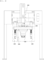
- FIG. 1 is a perspective view of a battery module inspection apparatus according to the present invention
- FIG. 2 is a front view of FIG. 1 .
- the battery module inspection apparatus includes a coupling portion 100 configured to be connected to a battery module connector, a stage 200 having the coupling portion 100 mounted to a lower part thereof, the stage being configured to move the coupling portion 100 in a horizontal direction, a driving portion 300 configured to move the stage 200 in an upward-downward direction, a pair of guide portions 400 disposed respectively at opposite sides of the coupling portion 100, the guide portions being configured to adjust the position of the coupling portion, and a shaft 500 configured to serve as a reference axis along which the stage 200 is moved in the upward-downward direction.
- each of the guide portions 400 and the coupling portion 100 are coupled to the stage 200 so as to be positionally fixed thereto.
- the stage 200 may be moved together with the guide portions 400, and movement of the coupling portion 100 may occur in conjunction with the movement of the stage 200 in the horizontal direction.
- the stage 200 is moved.
- the tip of the lower part of each of the guide portions 400 is moved downwards so as to be inserted into a recess-shaped guide portion coupling position of a battery module, movement of the stage 200 in the horizontal direction may occur, and the coupling portion 100 coupled to the stage 200 so as to be fixed thereto may be connected to the battery module connector due to the movement of the stage 200.
- the distance between the coupling portion 100 and each of the pair of guide portions 400 is equal to the distance between the battery module connector and the guide portion coupling position of the battery module.
- the coupling portion 100 is disposed above the battery module connector.
- the coupling portion 100 may also be moved downwards and connected to the battery module connector. That is, the stage 200 according to the present invention is movable in the horizontal direction together with upward-downward movement thereof by the driving portion 300.
- the stage 200 may be mounted to the driving portion 300, and a pneumatic cylinder may be used as the driving portion 300.
- the kind of the driving portion according to the present invention is not particularly restricted, and a conventional construction may be applied as long as the conventional construction is constituted by a structure and a power source capable of transferring the stage in the upward-downward direction and the horizontal direction.
- the distance between the driving portion 300 and the coupling portion 100 is long, force of the driving portion 300 may not be properly transferred to the coupling portion 100, whereby a phenomenon in which the coupling portion, which is located in front, is loosened may occur.
- a conventional battery module inspection apparatus is configured such that the distance between the driving portion and the coupling portion is 140 mm, it is more difficult to adjust the position of the coupling portion due to the above phenomenon.
- the distance between the driving portion 300 and the coupling portion 100 is set to less than 100 mm, specifically 80 mm, in order to solve the above problem.
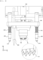
- FIG. 3 is a partial enlarged view of FIG. 2 .
- a guide pin 410 is added to the tip of the lower part of each of the guide portions 400. Since the guide pin 410 is made of a material having very small frictional force and is configured to have a structure capable of being inserted along a surface slope of the battery module, the coupling portion 100 may be easily horizontally moved in an x-axis direction and a y-axis direction.
- Each of the guide portions 400 includes a structure having a changeable length, such as a spring 440.
- a spring 440 When the stage 200 is moved in the upward-downward direction, i.e. a z-axis direction, the spring 440 may be contracted or extended, and the total length of each of the guide portions 400 may be increased or decreased.
- a connection part of the coupling portion 100 that is coupled to the battery module connector has a size corresponding to the area of the battery module connector, and a protrusion 110 is formed on a surface of the connection part.
- a protrusion 110 is formed on a surface of the connection part.
- an embossed structure such as a lattice structure, may be formed on the surface of the connection part.
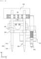
- FIG. 4 is a side view of FIG. 3
- FIG. 5 is a perspective view of a plate and the shaft.
- the stage 200 may be configured to have a quadrangular structure when viewed in plan and is movable along the shaft 500 as the reference axis in the upward-downward direction, i.e., the z-axis direction.
- the plate 220 is coupled to the lower part of the stage 200, and the stage 200 is moved together with the plate 220 in the horizontal direction (direction parallel to an x-y plane) and the upward-downward direction (z-axis direction).
- the shaft 500 extends through the plate 220 so as to be perpendicular to the plate 220, and the stage 200 and the plate 220 may be moved along the shaft 500 as the reference axis in the z-axis direction.
- the shaft 500 is located at two of four corner parts of the plate 220 such that the movement axis of the stage 200 in the upward-downward direction is uniformly maintained. Unlike what is shown in the figures, however, the number of shafts is not limited to two, and more than two shafts may be disposed. For example, the shaft may be located at each of the four corner parts of the plate, and the position of the shaft is not limited to each corner of the plate.
- the shaft 500 includes a cylindrical upper part 510 and a tapered part 520 having a diameter gradually decreased toward a tip of a lower part thereof.
- the diameter of a through-hole, through which the shaft 500 extends, formed in the plate 220 and the diameter of the shaft 500 have corresponding sizes.
- the plate 220 When the plate 220 is located at the upper part 510, the plate cannot be moved in the horizontal direction, i.e., the direction parallel to the x-y plane. In the state in which the plate 220 is moved downwards to the tapered part 520, however, the distance D is formed between the through-hole and the tapered part 520 in proportion to a decrease in diameter of the tapered part 520.
- the plate 220 may be moved in the x-axis direction and the y-axis direction by the distance D, and the stage 200 may be moved in the x-axis direction and the y-axis direction as the result of the movement of the plate 220.
- the movement range of the stage in the x-axis direction and the y-axis direction may be ⁇ 3 mm, specifically ⁇ 2.5 mm. Consequently, the distance D may be formed so as to be less than 3 mm.
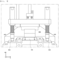
- FIG. 6 is a front view showing the state before the battery module inspection apparatus is coupled to the battery module
- FIG. 7 is a front view showing the state in which the battery module inspection apparatus is coupled to the battery module
- FIG. 8 is a side view of FIG. 6
- FIG. 9 is a side view of FIG. 7 .
- the battery module 900 is disposed at an inspection position, i.e. under the battery module inspection apparatus, and the stage 200 is moved downwards in the z-axis direction, whereby the coupling portion 100 is moved downwards in the z-axis direction.
- a pair of recesses 930, into which the pair of guide pins 410 formed respectively at the pair of guide portions 400 is inserted, is formed in the battery module 900, as the guide portion coupling position.
- the driving portion is moved downwards, whereby each of the guide pins 410 is located close to a corresponding one of the recesses 930, the guide pin 410 is inserted into the recess 930 while being moved toward the center of the recess 930 along the slope of the recesses 930.
- the stage 200 is moved in the horizontal direction, and the coupling portion 100 is located above the battery module connector 910 due to the movement of the stage 200.
- the coupling portion 100 is moved downwards along the shaft as the reference axis in the z-axis direction, and therefore the coupling portion 100 is connected to the battery module connector, as shown in FIGs. 7 and 9 .
- the stage is movable in the horizontal direction and the upward-downward direction. Even though position deviation of the battery module connector occurs, therefore, coupling between the coupling portion and the battery module connector may be accurately performed. Consequently, it is possible to prevent the occurrence of an error in inspecting the battery module.
Landscapes
- Chemical & Material Sciences (AREA)
- Chemical Kinetics & Catalysis (AREA)
- Electrochemistry (AREA)
- General Chemical & Material Sciences (AREA)
- Physics & Mathematics (AREA)
- General Physics & Mathematics (AREA)
- Engineering & Computer Science (AREA)
- Manufacturing & Machinery (AREA)
- Battery Mounting, Suspending (AREA)
- Secondary Cells (AREA)
Abstract
Description
- This application claims the benefit of priority to
Korean Patent Application No. 2021-0112263 filed on August 25, 2021 - The present invention relates to a battery module inspection apparatus having a positionally adjustable coupling portion. More particularly, the present invention relates to a battery module inspection apparatus configured such that the position of a coupling portion of the battery module inspection apparatus is adjustable such that the coupling portion can be coupled to a battery module connector even though position deviation of the battery module connector occurs in a battery module.
- Improvement in stability and increase in capacity of a lithium secondary battery, which is capable of being charged and discharged, have been rapidly achieved, and kinds of devices that use the lithium secondary battery as an energy source have been increased.
- For example, the lithium secondary battery has been widely used as an energy source for wireless mobile devices, which are small multifunctional products, or wearable devices, which are worn on the body, and has also been used as an energy source for electric vehicles and hybrid electric vehicles presented as alternatives to existing gasoline and diesel vehicles, which cause air pollution, or as an energy storage system (ESS).
- In order to use the lithium secondary battery as a high-output, high-capacity energy source, such as an energy source of an electric vehicle, a plurality of battery cells may be connected to each other in series and/or in parallel to manufacture a battery module.
- After assembly of the battery module including the plurality of battery cells, an inspection process for checking performance of the battery module is required.
- Specifically, in order to check whether individual battery cells are defective and to check the control state of the battery cells, a coupling portion of a battery module inspection apparatus may be coupled to a battery module connector, and voltages and temperatures of the battery cells may be measured to check whether the battery cells are defective.
- During a process of manufacturing the battery module, the battery module connector may be moved out of position due to movement of battery cells in a module case, whereby position deviation of the battery module connector may occur.
- However, a coupling portion of a conventional battery module inspection apparatus is configured such that the coupling portion is moved downwards toward the battery module connector in the state in which the battery module is disposed at an inspection position and is moved upwards to the original position thereof, i.e. the coupling portion is moved only in an upward-downward direction.
- If the position of the battery module connector is not aligned with the position of the coupling portion of the battery module inspection apparatus after being moved downwards, therefore, connection between the coupling portion of the battery module inspection apparatus and the battery module connector is difficult, which leads to poor inspection, whereby the battery module is reassembled, and therefore productivity is lowered.
- In connection therewith,
Patent Document 1 relates to an automatic connector connection apparatus for battery pack inspection, wherein a battery pack side connector is fixed by a clamp so as to be movable, and the battery pack side connector is electrically connected to or disconnected from an inspection apparatus side connector, whereby automatic connection and disconnection between the battery pack side connector and the inspection apparatus side connector is achieved. - In
Patent Document 1, the battery pack side connector, which is movable, is connected to the inspection apparatus side connector using the clamp, and therefore this patent document does not suggest a structure capable of preventing the occurrence of position deviation of a battery module connector when the battery module connector is configured to be fixed to an outer surface of a battery module. - Therefore, there is a need for a battery module inspection apparatus configured such that a coupling portion of the battery module inspection apparatus is accurately coupled to a battery module connector even though position deviation of the battery module connector occurs, thereby it is possible to prevent poor inspection.
- (Patent Document 1)
Japanese Patent Application Publication No. 2014-203628 (2014.10.27 - The present invention has been made in view of the above problems, and it is an object of the present invention to provide a battery module inspection apparatus having a positionally adjustable coupling portion configured such that the coupling portion of the battery module inspection apparatus is moved in a horizontal direction and a vertical direction, whereby the coupling portion is coupled to a battery module connector without an error in order to check whether a battery module is defective.
- A battery module inspection apparatus according to the present invention to accomplish the above object includes a coupling portion configured to be connected to a battery module connector, a stage having the coupling portion mounted to a lower part of the stage, the stage being configured to move the coupling portion in a horizontal direction, a driving portion configured to move the stage in an upward-downward direction, a pair of guide portions disposed respectively at opposite sides of the coupling portion, the guide portions being configured to adjust the position of the coupling portion, and a shaft configured to serve as a reference axis along which the stage is moved in the upward-downward direction.
- The battery module inspection apparatus may include a guide pin at a tip of a lower part of each of the guide portions.
- Each of the guide portions may have a structure in which the length of each of the guide portions is configured to increase or decrease based on a movement of the stage and the coupling portion in the upward-downward direction.
- An upper part of each of the guide portions and the coupling portion may be coupled to the stage so as to be fixed thereto, and the stage may be configured to be moved along a tip of a lower part of each of the guide portions.
- The coupling portion may be located above the battery module connector based on a movement of the stage.
- The battery module inspection apparatus may include a plate coupled to the lower part of the stage, wherein the shaft may be disposed such that the shaft extends through the plate and is perpendicular to the plate, and the stage and the coupling portion may be configured to be moved along the shaft as a reference axis in the upward-downward direction.
- The shaft may include a cylindrical upper part and a tapered part having a diameter gradually decreasing toward a tip of a lower part of the shaft.
- The coupling portion may be movable in the horizontal direction in proportion to a decrease in a diameter of the tapered part.
- The shaft may be located at at least two of corner parts of the plate.
- The coupling portion has a protrusion on a surface of a connection part of the coupling portion that is configured to be coupled to the battery module connector.
- The coupling portion may be configured to be positionally moved in conjunction with the movement of the stage in the horizontal direction.
- When the guide pin provided at the tip of the lower part of each of the guide portions is inserted into a recess formed in a battery module, the stage may be configured to be moved and the coupling portion may be configured to be disposed above the battery module connector.
- In addition, the present invention may provide various combinations of the above solving means.
- As is apparent from the above description, a battery module inspection apparatus according to the present invention includes a stage configured to allow a coupling portion connected to a battery module connector to be moved in a horizontal direction, whereby it is possible to accurately couple the coupling portion to the battery module connector even though position deviation of the battery module connector occurs.
- In addition, a protrusion is formed on a surface of the coupling portion, and the coupling portion has a large area, whereby the coupling portion may be stably connected to the battery module connector.
- In addition, since the stage is movable along a shaft in an upward-downward direction, the stage may be moved upwards along the shaft and may then return to the initial position thereof after inspection of a battery module is completed. Since the initial position of the coupling portion is always uniform, as described above, it is possible to secure stable connection between the coupling portion and the battery module connector even though position deviation of the battery module connector continuously occurs.
-
-
FIG. 1 is a perspective view of a battery module inspection apparatus according to the present invention. -
FIG. 2 is a front view ofFIG. 1 . -
FIG. 3 is a partial enlarged view ofFIG. 2 . -
FIG. 4 is a side view ofFIG. 3 . -
FIG. 5 is a perspective view of a plate and a shaft. -
FIG. 6 is a front view showing the state before the battery module inspection apparatus is coupled to a battery module. -
FIG. 7 is a front view showing the state in which the battery module inspection apparatus is coupled to the battery module. -
FIG. 8 is a side view ofFIG. 6 . -
FIG. 9 is a side view ofFIG. 7 . - Now, preferred embodiments of the present invention will be described in detail with reference to the accompanying drawings such that the preferred embodiments of the present invention can be easily implemented by a person having ordinary skill in the art to which the present invention pertains. In describing the principle of operation of the preferred embodiments of the present invention in detail, however, a detailed description of known functions and configurations incorporated herein will be omitted when the same may obscure the subject matter of the present invention.
- In addition, the same reference numbers will be used throughout the drawings to refer to parts that perform similar functions or operations.
- In the case in which one part is said to be connected to another part throughout the specification, not only may the one part be directly connected to the other part, but also, the one part may be indirectly connected to the other part via a further part. In addition, that a certain element is included does not mean that other elements are excluded, but means that such elements may be further included unless mentioned otherwise.
- In addition, a description to embody elements through limitation or addition may be applied to all inventions, unless particularly restricted, and does not limit a specific invention.
- Also, in the description of the invention and the claims of the present application, singular forms are intended to include plural forms unless mentioned otherwise.
- Also, in the description of the invention and the claims of the present application, "or" includes "and" unless mentioned otherwise. Therefore, "including A or B" means three cases, namely, the case including A, the case including B, and the case including A and B.
-
FIG. 1 is a perspective view of a battery module inspection apparatus according to the present invention, andFIG. 2 is a front view ofFIG. 1 . - Referring to
FIGs. 1 and2 , the battery module inspection apparatus according to the present invention includes acoupling portion 100 configured to be connected to a battery module connector, astage 200 having thecoupling portion 100 mounted to a lower part thereof, the stage being configured to move thecoupling portion 100 in a horizontal direction, adriving portion 300 configured to move thestage 200 in an upward-downward direction, a pair ofguide portions 400 disposed respectively at opposite sides of thecoupling portion 100, the guide portions being configured to adjust the position of the coupling portion, and ashaft 500 configured to serve as a reference axis along which thestage 200 is moved in the upward-downward direction. - An upper part of each of the
guide portions 400 and thecoupling portion 100 are coupled to thestage 200 so as to be positionally fixed thereto. When theguide portions 400 are moved, therefore, thestage 200 may be moved together with theguide portions 400, and movement of thecoupling portion 100 may occur in conjunction with the movement of thestage 200 in the horizontal direction. - That is, as the position of a tip of a lower part of each of the
guide portions 400 is moved, thestage 200 is moved. When the tip of the lower part of each of theguide portions 400 is moved downwards so as to be inserted into a recess-shaped guide portion coupling position of a battery module, movement of thestage 200 in the horizontal direction may occur, and thecoupling portion 100 coupled to thestage 200 so as to be fixed thereto may be connected to the battery module connector due to the movement of thestage 200. - The distance between the
coupling portion 100 and each of the pair ofguide portions 400 is equal to the distance between the battery module connector and the guide portion coupling position of the battery module. When theguide portions 400 are moved to the guide portion coupling position, thecoupling portion 100 is disposed above the battery module connector. - When the
guide portions 400 are moved downwards while being inserted into the guide portion coupling position in this state, thecoupling portion 100 may also be moved downwards and connected to the battery module connector. That is, thestage 200 according to the present invention is movable in the horizontal direction together with upward-downward movement thereof by the drivingportion 300. For the upward-downward movement of thestage 200, thestage 200 may be mounted to the drivingportion 300, and a pneumatic cylinder may be used as the drivingportion 300. The kind of the driving portion according to the present invention is not particularly restricted, and a conventional construction may be applied as long as the conventional construction is constituted by a structure and a power source capable of transferring the stage in the upward-downward direction and the horizontal direction. - Meanwhile, if the distance between the driving
portion 300 and thecoupling portion 100 is long, force of the drivingportion 300 may not be properly transferred to thecoupling portion 100, whereby a phenomenon in which the coupling portion, which is located in front, is loosened may occur. For example, when a conventional battery module inspection apparatus is configured such that the distance between the driving portion and the coupling portion is 140 mm, it is more difficult to adjust the position of the coupling portion due to the above phenomenon. - In the present invention, therefore, the distance between the driving
portion 300 and thecoupling portion 100 is set to less than 100 mm, specifically 80 mm, in order to solve the above problem. -
FIG. 3 is a partial enlarged view ofFIG. 2 . - Referring to
FIG. 3 , aguide pin 410 is added to the tip of the lower part of each of theguide portions 400. Since theguide pin 410 is made of a material having very small frictional force and is configured to have a structure capable of being inserted along a surface slope of the battery module, thecoupling portion 100 may be easily horizontally moved in an x-axis direction and a y-axis direction. - Each of the
guide portions 400 includes a structure having a changeable length, such as aspring 440. When thestage 200 is moved in the upward-downward direction, i.e. a z-axis direction, thespring 440 may be contracted or extended, and the total length of each of theguide portions 400 may be increased or decreased. - A connection part of the
coupling portion 100 that is coupled to the battery module connector has a size corresponding to the area of the battery module connector, and aprotrusion 110 is formed on a surface of the connection part. In a conventional case in which a single cone is formed on the entirety of the connection part, there is a problem in that connection between a tip of the cone and the battery module connector is not well achieved. In contrast, when a plurality of protrusions is formed on the surface of the connection part, as in the present invention, contact between the battery module connector and the coupling portion is more easily achieved. - Although the plurality of protrusions is formed on the surface of the connection part, an embossed structure, such as a lattice structure, may be formed on the surface of the connection part.
-
FIG. 4 is a side view ofFIG. 3 , andFIG. 5 is a perspective view of a plate and the shaft. - Referring to
FIGs. 4 and5 , thestage 200 according to the present invention may be configured to have a quadrangular structure when viewed in plan and is movable along theshaft 500 as the reference axis in the upward-downward direction, i.e., the z-axis direction. - The
plate 220 is coupled to the lower part of thestage 200, and thestage 200 is moved together with theplate 220 in the horizontal direction (direction parallel to an x-y plane) and the upward-downward direction (z-axis direction). Theshaft 500 extends through theplate 220 so as to be perpendicular to theplate 220, and thestage 200 and theplate 220 may be moved along theshaft 500 as the reference axis in the z-axis direction. - The
shaft 500 is located at two of four corner parts of theplate 220 such that the movement axis of thestage 200 in the upward-downward direction is uniformly maintained. Unlike what is shown in the figures, however, the number of shafts is not limited to two, and more than two shafts may be disposed. For example, the shaft may be located at each of the four corner parts of the plate, and the position of the shaft is not limited to each corner of the plate. - The
shaft 500 includes a cylindricalupper part 510 and atapered part 520 having a diameter gradually decreased toward a tip of a lower part thereof. - The diameter of a through-hole, through which the
shaft 500 extends, formed in theplate 220 and the diameter of theshaft 500 have corresponding sizes. When theplate 220 is located at theupper part 510, the plate cannot be moved in the horizontal direction, i.e., the direction parallel to the x-y plane. In the state in which theplate 220 is moved downwards to thetapered part 520, however, the distance D is formed between the through-hole and thetapered part 520 in proportion to a decrease in diameter of thetapered part 520. Consequently, theplate 220 may be moved in the x-axis direction and the y-axis direction by the distance D, and thestage 200 may be moved in the x-axis direction and the y-axis direction as the result of the movement of theplate 220. - In consideration of the fact that the position deviation of the battery module connector is generally is less than ±1 mm, the movement range of the stage in the x-axis direction and the y-axis direction may be ±3 mm, specifically ±2.5 mm. Consequently, the distance D may be formed so as to be less than 3 mm.
-
FIG. 6 is a front view showing the state before the battery module inspection apparatus is coupled to the battery module,FIG. 7 is a front view showing the state in which the battery module inspection apparatus is coupled to the battery module,FIG. 8 is a side view ofFIG. 6 , andFIG. 9 is a side view ofFIG. 7 . - Referring to
FIGs. 6 to 9 , thebattery module 900 is disposed at an inspection position, i.e. under the battery module inspection apparatus, and thestage 200 is moved downwards in the z-axis direction, whereby thecoupling portion 100 is moved downwards in the z-axis direction. - A pair of
recesses 930, into which the pair of guide pins 410 formed respectively at the pair ofguide portions 400 is inserted, is formed in thebattery module 900, as the guide portion coupling position. When the driving portion is moved downwards, whereby each of the guide pins 410 is located close to a corresponding one of therecesses 930, theguide pin 410 is inserted into therecess 930 while being moved toward the center of therecess 930 along the slope of therecesses 930. - When the
guide pin 410 is moved so as to be inserted into therecess 930, as described above, thestage 200 is moved in the horizontal direction, and thecoupling portion 100 is located above thebattery module connector 910 due to the movement of thestage 200. - When the
guide pin 410 is inserted into therecess 930 in this state, thecoupling portion 100 is moved downwards along the shaft as the reference axis in the z-axis direction, and therefore thecoupling portion 100 is connected to the battery module connector, as shown inFIGs. 7 and9 . - When the battery module is inspected using the battery module inspection apparatus according to the present invention, as described above, the stage is movable in the horizontal direction and the upward-downward direction. Even though position deviation of the battery module connector occurs, therefore, coupling between the coupling portion and the battery module connector may be accurately performed. Consequently, it is possible to prevent the occurrence of an error in inspecting the battery module.
- Those skilled in the art to which the present invention pertains will appreciate that various applications and modifications are possible within the category of the present invention based on the above description.
-
- 100:
- Coupling portion
- 110:
- Protrusion
- 200:
- Stage
- 220:
- Plate
- 300:
- Driving portion
- 400:
- Guide portion
- 410:
- Guide pin
- 440:
- Spring
- 500:
- Shaft
- 510:
- Upper part
- 520:
- Tapered part
- 900:
- Battery module
- 910:
- Battery module connector
- 930:
- Recess
Claims (12)
- A battery module inspection apparatus, comprising:a coupling portion configured to be connected to a battery module connector;a stage having the coupling portion mounted to a lower part of the stage, the stage being configured to move the coupling portion in a horizontal direction;a driving portion configured to move the stage in an upward-downward direction;a pair of guide portions disposed respectively at opposite sides of the coupling portion, the guide portions being configured to adjust a position of the coupling portion; anda shaft configured to serve as a reference axis along which the stage is moved in the upward-downward direction.
- The battery module inspection apparatus according to claim 1, further comprising a guide pin at a tip of a lower part of each of the guide portions.
- The battery module inspection apparatus according to claim 1, wherein each of the guide portions has a structure in which a length of each of the guide portions is configured to increase or decrease based on a movement of the stage and the coupling portion in the upward-downward direction.
- The battery module inspection apparatus according to claim 1, whereinan upper part of each of the guide portions and the coupling portion are coupled to the stage so as to be fixed thereto, andthe stage is configured to be moved along a tip of a lower part of each of the guide portions.
- The battery module inspection apparatus according to claim 4, wherein the coupling portion is located above the battery module connector based on a movement of the stage.
- The battery module inspection apparatus according to claim 1, further comprising:a plate coupled to the lower part of the stage,wherein the shaft is disposed such that the shaft extends through the plate and is perpendicular to the plate, andwherein the stage and the coupling portion are configured to be moved along the shaft as a reference axis in the upward-downward direction.
- The battery module inspection apparatus according to claim 1, wherein the shaft comprises:a cylindrical upper part; anda tapered part having a diameter gradually decreasing toward a tip of a lower part of the shaft.
- The battery module inspection apparatus according to claim 7, wherein the coupling portion is movable in the horizontal direction in proportion to a decrease in a diameter of the tapered part.
- The battery module inspection apparatus according to claim 6, wherein the shaft is located at at least two of corner parts of the plate.
- The battery module inspection apparatus according to claim 1, wherein the coupling portion has a protrusion on a surface of a connection part of the coupling portion that is configured to be coupled to the battery module connector.
- The battery module inspection apparatus according to claim 1, wherein the coupling portion is configured to be positionally moved in conjunction with a movement of the stage in the horizontal direction.
- The battery module inspection apparatus according to claim 2, wherein, when the guide pin provided at the tip of the lower part of each of the guide portions is inserted into a recess formed in a battery module, the stage is configured to be moved and the coupling portion is configured to be disposed above the battery module connector.
Applications Claiming Priority (2)
| Application Number | Priority Date | Filing Date | Title |
|---|---|---|---|
| KR1020210112263A KR102932146B1 (en) | 2021-08-25 | 2021-08-25 | Battery Module Inspection Device Capable of Adjusting Position of Coupling Part |
| PCT/KR2022/012699 WO2023027520A1 (en) | 2021-08-25 | 2022-08-25 | Battery module inspection device capable of adjusting location of connection part |
Publications (2)
| Publication Number | Publication Date |
|---|---|
| EP4220813A1 true EP4220813A1 (en) | 2023-08-02 |
| EP4220813A4 EP4220813A4 (en) | 2025-05-07 |
Family
ID=85321941
Family Applications (1)
| Application Number | Title | Priority Date | Filing Date |
|---|---|---|---|
| EP22861728.8A Pending EP4220813A4 (en) | 2021-08-25 | 2022-08-25 | BATTERY MODULE INSPECTION DEVICE CAPABLE OF ADJUSTING THE LOCATION OF A CONNECTION PART |
Country Status (6)
| Country | Link |
|---|---|
| US (1) | US12292478B2 (en) |
| EP (1) | EP4220813A4 (en) |
| JP (1) | JP7520451B2 (en) |
| KR (1) | KR102932146B1 (en) |
| CN (1) | CN116508198A (en) |
| WO (1) | WO2023027520A1 (en) |
Families Citing this family (2)
| Publication number | Priority date | Publication date | Assignee | Title |
|---|---|---|---|---|
| KR20250003173A (en) * | 2023-06-30 | 2025-01-07 | 주식회사 엘지에너지솔루션 | Device for inspecting connector |
| CN118625168B (en) * | 2024-06-03 | 2024-11-19 | 山东腾翔产品质量检测有限公司 | A lithium-ion battery explosion-proof test box |
Family Cites Families (18)
| Publication number | Priority date | Publication date | Assignee | Title |
|---|---|---|---|---|
| JP2678875B2 (en) | 1993-10-14 | 1997-11-19 | 日本航空電子工業株式会社 | Connector inspection jig |
| JPH09106876A (en) | 1995-08-09 | 1997-04-22 | Yazaki Corp | Terminal insertion device, terminal insertion method, and connector holding structure |
| JP4455751B2 (en) | 2000-12-28 | 2010-04-21 | アイシン精機株式会社 | Deburring inspection device |
| KR100392229B1 (en) * | 2001-01-09 | 2003-07-22 | 미래산업 주식회사 | Index head of handler for testing semiconductor |
| JP4335479B2 (en) | 2001-07-27 | 2009-09-30 | 独立行政法人 宇宙航空研究開発機構 | Electrical connection device |
| KR100524419B1 (en) * | 2003-07-03 | 2005-10-26 | 주식회사 이랜텍 | Index table test equipment of battery |
| JP3150375U (en) | 2009-02-26 | 2009-05-07 | 日清紡ホールディングス株式会社 | Connector removal device for solar panel |
| JP6088145B2 (en) | 2012-02-13 | 2017-03-01 | オートモーティブエナジーサプライ株式会社 | Battery manufacturing method and conductivity inspection apparatus |
| JP2014203628A (en) | 2013-04-03 | 2014-10-27 | トヨタ自動車株式会社 | Connector automatically connecting device for battery pack inspection |
| KR101529265B1 (en) | 2014-04-07 | 2015-06-17 | (주) 루켄테크놀러지스 | Inspecting apparatus for electronic device |
| JP6292023B2 (en) | 2014-05-20 | 2018-03-14 | 日産自動車株式会社 | Polygon member alignment device |
| KR101630214B1 (en) | 2015-01-19 | 2016-06-14 | 김종근 | Clamping device for polymer ce11 battery |
| US10151789B2 (en) * | 2015-02-09 | 2018-12-11 | Acculogic Corporation | Method and device for testing the connections of batteries |
| KR101937995B1 (en) | 2015-06-04 | 2019-01-11 | 주식회사 엘지화학 | Test Device for function of Battery Pack |
| KR101969320B1 (en) * | 2017-07-13 | 2019-04-17 | 주식회사 티피엠에스 | Batterty jig box for charging and discharging inspection, and testing apparatus using the same |
| JP2020061590A (en) | 2020-01-23 | 2020-04-16 | 東京エレクトロン株式会社 | Wafer inspection apparatus and wafer inspection method |
| KR20210112263A (en) | 2020-03-04 | 2021-09-14 | 한국전자통신연구원 | Method for generating virtual viewpoint image nad apparatus for the same |
| KR102187649B1 (en) | 2020-03-13 | 2020-12-07 | 주식회사 아라(Ara) | System for connecting and un connecting connector for test |
-
2021
- 2021-08-25 KR KR1020210112263A patent/KR102932146B1/en active Active
-
2022
- 2022-08-25 WO PCT/KR2022/012699 patent/WO2023027520A1/en not_active Ceased
- 2022-08-25 US US18/030,588 patent/US12292478B2/en active Active
- 2022-08-25 CN CN202280007374.9A patent/CN116508198A/en active Pending
- 2022-08-25 EP EP22861728.8A patent/EP4220813A4/en active Pending
- 2022-08-25 JP JP2023528185A patent/JP7520451B2/en active Active
Also Published As
| Publication number | Publication date |
|---|---|
| WO2023027520A1 (en) | 2023-03-02 |
| US12292478B2 (en) | 2025-05-06 |
| EP4220813A4 (en) | 2025-05-07 |
| KR102932146B1 (en) | 2026-02-27 |
| JP7520451B2 (en) | 2024-07-23 |
| JP2023548926A (en) | 2023-11-21 |
| US20230366934A1 (en) | 2023-11-16 |
| CN116508198A (en) | 2023-07-28 |
| KR20230030255A (en) | 2023-03-06 |
Similar Documents
| Publication | Publication Date | Title |
|---|---|---|
| US12292478B2 (en) | Battery module inspection apparatus having positionally adjustable coupling portion | |
| KR102015898B1 (en) | Folding Device for electrode lead Part of Battery Cell | |
| KR101451319B1 (en) | Secondary battery charge and discharge probe | |
| US11424514B2 (en) | Battery module having electrode tab with protrusion | |
| US11865587B2 (en) | Cylindrical battery cell sorting apparatus and sorting method using the same | |
| US20250028004A1 (en) | Battery module charge and discharge inspection system and method thereof | |
| KR102316702B1 (en) | Cylindrical battery cell jig | |
| CN106410257B (en) | Winding support core, secondary battery, method of manufacturing the same, and battery winding machine | |
| KR102894622B1 (en) | Jig assembly for bolting and battery pack assembly method using the same | |
| JP2010061831A (en) | Automatic connection device of connection member of fuel cell and inspection device | |
| KR20210035508A (en) | Battery Module | |
| KR20240158592A (en) | Assembly guide and battery module manufacturing method | |
| KR20230035806A (en) | Battery cell automatic insertion device | |
| US12394814B2 (en) | Material transferring apparatus for battery manufacturing | |
| CN223711794U (en) | A battery cell open-circuit voltage testing device and battery cell production system | |
| CN223218425U (en) | Battery module | |
| KR100858805B1 (en) | Probe and Battery Charger | |
| US20250201994A1 (en) | Battery mounting device | |
| KR102843938B1 (en) | Apparatus for manufacturing secondary battery pack with the guide block | |
| KR102878965B1 (en) | Busbar assembly with a device for fixing the bent shape of the busbar | |
| US20240387955A1 (en) | Cylindrical battery cell having connection member mounted thereto and battery module including the same | |
| KR20260069422A (en) | Voltage Measuring Unit, Battery Cell Pressing Jig Comprising the Same and Charging/Discharging Device Comprising the Battery Cell Pressing Jig | |
| KR20260055624A (en) | Battery cell measuring device | |
| US20250316851A1 (en) | Battery pack | |
| US20240380051A1 (en) | Alignment mechanism |
Legal Events
| Date | Code | Title | Description |
|---|---|---|---|
| STAA | Information on the status of an ep patent application or granted ep patent |
Free format text: STATUS: THE INTERNATIONAL PUBLICATION HAS BEEN MADE |
|
| PUAI | Public reference made under article 153(3) epc to a published international application that has entered the european phase |
Free format text: ORIGINAL CODE: 0009012 |
|
| STAA | Information on the status of an ep patent application or granted ep patent |
Free format text: STATUS: REQUEST FOR EXAMINATION WAS MADE |
|
| 17P | Request for examination filed |
Effective date: 20230427 |
|
| AK | Designated contracting states |
Kind code of ref document: A1 Designated state(s): AL AT BE BG CH CY CZ DE DK EE ES FI FR GB GR HR HU IE IS IT LI LT LU LV MC MK MT NL NO PL PT RO RS SE SI SK SM TR |
|
| DAV | Request for validation of the european patent (deleted) | ||
| DAX | Request for extension of the european patent (deleted) | ||
| A4 | Supplementary search report drawn up and despatched |
Effective date: 20250403 |
|
| RIC1 | Information provided on ipc code assigned before grant |
Ipc: G01R 31/36 20200101ALI20250328BHEP Ipc: G01R 31/364 20190101ALI20250328BHEP Ipc: G01R 31/385 20190101ALI20250328BHEP Ipc: H01M 50/204 20210101ALI20250328BHEP Ipc: H01M 10/42 20060101AFI20250328BHEP |
|
| STAA | Information on the status of an ep patent application or granted ep patent |
Free format text: STATUS: EXAMINATION IS IN PROGRESS |
|
| 17Q | First examination report despatched |
Effective date: 20251208 |