EP4220791A1 - Electric storage device - Google Patents
Electric storage device Download PDFInfo
- Publication number
- EP4220791A1 EP4220791A1 EP22213644.2A EP22213644A EP4220791A1 EP 4220791 A1 EP4220791 A1 EP 4220791A1 EP 22213644 A EP22213644 A EP 22213644A EP 4220791 A1 EP4220791 A1 EP 4220791A1
- Authority
- EP
- European Patent Office
- Prior art keywords
- submersion
- battery pack
- immersion
- battery
- battery packs
- Prior art date
- Legal status (The legal status is an assumption and is not a legal conclusion. Google has not performed a legal analysis and makes no representation as to the accuracy of the status listed.)
- Granted
Links
Images


Classifications
-
- H—ELECTRICITY
- H01—ELECTRIC ELEMENTS
- H01M—PROCESSES OR MEANS, e.g. BATTERIES, FOR THE DIRECT CONVERSION OF CHEMICAL ENERGY INTO ELECTRICAL ENERGY
- H01M10/00—Secondary cells; Manufacture thereof
- H01M10/04—Construction or manufacture in general
- H01M10/0472—Vertically superposed cells with vertically disposed plates
-
- H—ELECTRICITY
- H01—ELECTRIC ELEMENTS
- H01M—PROCESSES OR MEANS, e.g. BATTERIES, FOR THE DIRECT CONVERSION OF CHEMICAL ENERGY INTO ELECTRICAL ENERGY
- H01M10/00—Secondary cells; Manufacture thereof
- H01M10/42—Methods or arrangements for servicing or maintenance of secondary cells or secondary half-cells
- H01M10/425—Structural combination with electronic components, e.g. electronic circuits integrated to the outside of the casing
-
- H—ELECTRICITY
- H01—ELECTRIC ELEMENTS
- H01M—PROCESSES OR MEANS, e.g. BATTERIES, FOR THE DIRECT CONVERSION OF CHEMICAL ENERGY INTO ELECTRICAL ENERGY
- H01M10/00—Secondary cells; Manufacture thereof
- H01M10/42—Methods or arrangements for servicing or maintenance of secondary cells or secondary half-cells
- H01M10/48—Accumulators combined with arrangements for measuring, testing or indicating the condition of cells, e.g. the level or density of the electrolyte
- H01M10/488—Cells or batteries combined with indicating means for external visualization of the condition, e.g. by change of colour or of light density
-
- H—ELECTRICITY
- H01—ELECTRIC ELEMENTS
- H01M—PROCESSES OR MEANS, e.g. BATTERIES, FOR THE DIRECT CONVERSION OF CHEMICAL ENERGY INTO ELECTRICAL ENERGY
- H01M50/00—Constructional details or processes of manufacture of the non-active parts of electrochemical cells other than fuel cells, e.g. hybrid cells
- H01M50/20—Mountings; Secondary casings or frames; Racks, modules or packs; Suspension devices; Shock absorbers; Transport or carrying devices; Holders
- H01M50/244—Secondary casings; Racks; Suspension devices; Carrying devices; Holders characterised by their mounting method
-
- H—ELECTRICITY
- H01—ELECTRIC ELEMENTS
- H01M—PROCESSES OR MEANS, e.g. BATTERIES, FOR THE DIRECT CONVERSION OF CHEMICAL ENERGY INTO ELECTRICAL ENERGY
- H01M50/00—Constructional details or processes of manufacture of the non-active parts of electrochemical cells other than fuel cells, e.g. hybrid cells
- H01M50/20—Mountings; Secondary casings or frames; Racks, modules or packs; Suspension devices; Shock absorbers; Transport or carrying devices; Holders
- H01M50/251—Mountings; Secondary casings or frames; Racks, modules or packs; Suspension devices; Shock absorbers; Transport or carrying devices; Holders specially adapted for stationary devices, e.g. power plant buffering or backup power supplies
-
- H—ELECTRICITY
- H01—ELECTRIC ELEMENTS
- H01M—PROCESSES OR MEANS, e.g. BATTERIES, FOR THE DIRECT CONVERSION OF CHEMICAL ENERGY INTO ELECTRICAL ENERGY
- H01M2220/00—Batteries for particular applications
- H01M2220/10—Batteries in stationary systems, e.g. emergency power source in plant
-
- Y—GENERAL TAGGING OF NEW TECHNOLOGICAL DEVELOPMENTS; GENERAL TAGGING OF CROSS-SECTIONAL TECHNOLOGIES SPANNING OVER SEVERAL SECTIONS OF THE IPC; TECHNICAL SUBJECTS COVERED BY FORMER USPC CROSS-REFERENCE ART COLLECTIONS [XRACs] AND DIGESTS
- Y02—TECHNOLOGIES OR APPLICATIONS FOR MITIGATION OR ADAPTATION AGAINST CLIMATE CHANGE
- Y02E—REDUCTION OF GREENHOUSE GAS [GHG] EMISSIONS, RELATED TO ENERGY GENERATION, TRANSMISSION OR DISTRIBUTION
- Y02E60/00—Enabling technologies; Technologies with a potential or indirect contribution to GHG emissions mitigation
- Y02E60/10—Energy storage using batteries
Definitions
- the present invention relates to an electric storage device.
- a battery pack using small lithium ion batteries has a small battery capacity, and therefore cannot be used as it is for household power.
- a streetlight electric storage device Further, the streetlight may be a solar-type streetlight (hereinafter referred to as a "solar streetlight").
- Performance such as capacity and internal resistance of a battery pack collected from the market is deteriorated as compared to a new battery pack, and performance varies among battery packs. In consideration of such circumstances, it is necessary to increase the capacity by combining a plurality of battery packs when reusing battery packs.
- WO2017/029715 discloses a storage battery control device aimed to, when an anomaly occurs due to a disaster such as an earthquake, a tsunami, wind and flood damage, or fire, discharge electricity stored in a storage battery and reduce the possibility of a secondary disaster compared with prior art.
- the storage battery control device includes an electricity control unit that, when it is determined that an anomaly has occurred on the basis of a signal received from an anomaly detection unit, causes an electricity consumption unit to consume electricity stored in the storage battery and lowers the electricity amount of the storage battery to equal to or less than a set charge amount.
- WO2017/029715 discloses that the anomaly detection unit is an immersion sensor that detects presence or absence of water immersion. According to such a configuration, the storage battery control device described in WO2017/029715 can detect anomaly due to water immersion, and can discharge the storage battery before an electricity storage system is damaged by water immersion.
- Patent Literature 1 WO2017/029715
- the storage battery control device described in WO2017/029715 has a problem that information on water immersion (hereinafter referred to as “immersion information”) cannot be recognized outside the electricity storage system.
- the present invention has been made in view of the foregoing, and aims to provide an electric storage device that can give notification of immersion information to the outside.
- the present invention is an electric storage device including: a plurality of battery packs capable of supplying electricity to a predetermined load, and installed to align in an up-down direction inside a columnar member; a control device that is arranged above the battery packs and controls the battery packs; a submersion sensor provided in each of the plurality of battery packs; and a notification unit that gives notification of information regarding immersion to the outside,
- the control device includes a communication unit that receives information indicating submersion from the submersion sensor in each battery pack, a determination unit that determines a degree of immersion on a basis of which of the submersion sensors having transmitted the received information indicating submersion, and a control unit that controls the notification unit to give notification of immersion degree information indicating the degree of immersion determined by the determination unit to the outside.
- an electric storage device that can give notification of immersion information to the outside.
- An electric storage device is characterized by including: a plurality of battery packs capable of supplying electricity to a predetermined load, and installed to align in an up-down direction inside a columnar member; a control device that is arranged above the battery packs and controls the battery packs; a submersion sensor provided in each of the plurality of battery packs; and a notification unit that gives notification of information regarding immersion to the outside, in which the control device includes a communication unit that receives information indicating submersion from the submersion sensor in each battery pack, a determination unit that determines a degree of immersion on a basis of which of the submersion sensors having transmitted the received information indicating submersion, and a control unit that controls the notification unit to give notification of immersion degree information indicating the degree of immersion determined by the determination unit to the outside.
- the electric storage device can give notification of immersion information to the outside.
- the present example is described by using an electric storage device used for a solar streetlight installed outside as an example.
- a solar streetlight 1 as a streetlight includes a columnar member 2, a solar panel 3, an illumination device 4 as a predetermined load, a plurality of battery packs 5, and a control device 6.
- the solar streetlight 1 is installed on a ground G.
- the illumination device 4 side is defined as “front,” the opposite side thereof is defined as “back,” when viewing the front side from the back side, the left side is defined as “left,” the right side is defined as “right,” and the upper side is defined as “up.”
- a side surface on which the illumination device 4 is installed is the front side of the solar streetlight 1.
- the columnar member 2 is formed of a square pole, and is formed in a hollow shape having a space on the inside.
- the columnar member 2 can also adopt shapes other than the square pole, such as a prism or a cylinder.
- a plurality of battery packs 5 capable of supplying electricity to the illumination device 4 and the control device 6 are installed inside the columnar member 2.
- the control device 6 is disposed above the plurality of battery packs 5 inside the columnar member 2.
- a first opening 21 and a second opening 22 located above the first opening 21 are formed on a side surface 2a on the front side of the columnar member 2.
- the first opening 21 is provided in the installation position of the plurality of battery packs 5.
- the first opening 21 is used when performing work such as replacing the battery pack 5 and performing maintenance, for example, and is closed by a lid 21a when the work is not performed.
- the second opening 22 is provided in the installation position of the control device 6.
- the second opening 22 is used when operating the control device 6 or performing maintenance work, for example, and is closed by a lid 22a when the operation and work are not performed.
- the installation area of the plurality of battery packs 5 inside the columnar member 2 is longer than the installation area of the control device 6 in the height direction of the columnar member 2, and therefore the first opening 21 is longer than the second opening 22 in the height direction.
- a drainpipe 25 embedded below the ground G is connected to a bottom part of the columnar member 2.
- the drainpipe 25 is a pipe for draining moist that pools in the bottom part of the columnar member 2 to the underground as wastewater.
- the solar panel 3 is attached to a top 23 of the columnar member 2.
- the solar panel 3 is formed of a photovoltaic module that generates electricity using optical energy from the sun, and is adjusted according to the installation location of the solar streetlight 1, so that the solar panel 3 is oriented to obtain the maximum amount of solar radiation throughout the year.
- the solar panel 3 is connected to the battery pack 5 and the control device 6 to be able to supply electricity thereto.
- the illumination device 4 is disposed in an upper part of the side surface 2a on the front side of the columnar member 2, and shines a downward light from an upper part of the columnar member 2.
- the battery pack 5 is a reused vehicle battery pack that had been mounted on a vehicle.
- a plurality of battery packs 5 are combined to increase the capacity for use.
- the battery pack 5 is formed in a rectangular parallelepiped shape in which a side in the vertical direction is shorter than a side in the horizontal direction when placed in the transverse direction. "Placed in the transverse direction” refers to how the battery pack 5 is placed when mounted on a vehicle, and is how the battery pack 5 is placed so that its thickness is minimized.
- the battery pack 5 is mounted so as to be placed in the vertical direction inside the columnar member 2. Moreover, in the present example, the vertically placed plurality of battery packs 5 are arranged to align in the up-down direction inside the columnar member 2.
- the plurality of battery packs 5 arranged in the up-down direction inside the columnar member 2 form a battery pack group.
- five battery packs 5 arranged in the up-down direction form one battery pack group.
- the number of battery packs 5 included in a battery pack group is arbitrary, and is not limited to five.
- two rows of the battery pack groups are provided inside the columnar member 2. Of the two rows of battery pack groups, one is referred to as a battery pack group 5A, and the other is referred to as a battery pack group 5B.
- the number of rows of the battery pack groups provided inside the columnar member 2 is not limited to two, and may be one, or three or more, for example.
- the battery packs 5 of the same battery pack group are connected to the same wiring. Specifically, the five battery packs 5 included in the battery pack group 5A are connected to wiring 50A, and the five battery packs 5 included in the battery pack group 5B are connected to wiring 50B.
- the wiring 50A and the wiring 50B are routed in the up-down direction inside the columnar member 2.
- a positive terminal 60 and a power supply terminal 63 described later of each battery pack 5, the solar panel 3, the illumination device 4, the control device 6, and the like of the corresponding battery pack group are connected to each of the wiring 50A and the wiring 50B.
- the battery pack group 5A and the battery pack group 5B form different battery pack group systems, and can function independently. For this reason, even when a trouble occurs in one system, the battery pack can be operated by the other system in which no trouble has occurred.
- the control device 6 is connected to a battery management system (BMS) 55 (see Figure 2 ) described later in the battery pack 5, and controls the plurality of battery packs 5 via the BMS 55.
- BMS battery management system
- the control device 6 exchanges information with the BMS 55 through communication.
- the control device 6 is formed of a computer unit including a central processing unit (CPU), a random access memory (RAM), a read only memory (ROM), an input port, and an output port.
- a program for causing the computer unit to function as the control device 6 is stored, together with various constants and the like, in the ROM of the computer unit. That is, the CPU executing the program stored in the ROM by using the RAM as a work area causes the computer unit to function as the control device 6 of the present example.
- Various sensors 7 are connected to the control device 6.
- sensors capable of detecting a change in the external environment such as an illumination sensor are connected to the control device 6.
- the control device 6 may include a timer that manages the lighting duration and lighting time. A configuration of the control device 6 will be described in detail later.
- the battery pack 5 includes a battery 53, a relay 54, a BMS 55, and a submersion sensor 56.
- the battery 53, the relay 54, the BMS 55, and the submersion sensor 56 are provided inside the battery pack 5.
- the battery 53 is formed of a chargeable and dischargeable secondary battery such as a lithium ion battery.
- the battery 53 has a positive electrode 53a and a negative electrode 53b.
- the positive electrode 53a of the battery 53 is connected to the positive terminal 60 via the relay 54 so as to be electrically conductive.
- the positive terminal 60 is a terminal that outputs the voltage of the battery 53 to the outside of the battery pack 5, and is exposed to the outside of the battery pack 5.
- the negative electrode 53b of the battery 53 is connected to a case of the battery pack 5 via a ground terminal 61.
- the relay 54 is a switch that is provided between the positive electrode 53a of the battery 53 and the positive terminal 60, and is capable of switching between a connected state in which the positive electrode 53a of the battery 53 and the positive terminal 60 are connected and a disconnected state in which the two are disconnected.
- the relay 54 is switched to the disconnected state when submersion of the battery pack 5 is detected by the submersion sensor 56.
- the BMS 55 monitors and manages states of the battery 53 such as the voltage value and the state of charge (SOC) of the battery 53.
- the BMS 55 calculates the SOC on the basis of the charging and discharging current of the battery 53.
- the BMS 55 controls switching between the connected state and disconnected state of the relay 54.
- the BMS 55 is connected to the control device 6 through a communication terminal 62 provided in the battery pack 5.
- the BMS 55 is connected to the power supply via the power supply terminal 63 and a power supply GND terminal 64 provided in the battery pack 5.
- the battery 53 and the solar panel 3 are used as the power supply.
- the submersion sensor 56 is a sensor that detects submersion of the battery pack 5.
- Various submersion sensors such as a sensor that detects submersion by sensing hydraulic pressure of a predetermined pressure or greater indicating submersion, a sensor that detects submersion when positive and negative terminals are submerged in water and there is continuity between the terminals, or the like can be used as the submersion sensor 56.
- the battery pack 5 is installed in the vertical direction inside the columnar member 2 to be oriented so that the positive terminal 60 is located above the submersion sensor 56. As a result, the positive terminal 60 is located above the submersion sensor 56.
- the control device 6 has a function as a communication unit 71 that receives information indicating submersion from the submersion sensor 56 in each battery pack 5.
- the control device 6 has a function as a determination unit 72 that determines the degree of immersion on the basis of which of the submersion sensors 56 in the battery packs 5 having transmitted the received information indicating submersion.
- the ROM of the control device 6 stores, for each battery pack 5, the height from the ground G to the installation position of the battery pack 5 as height information.
- the control device 6 can identify the battery pack 5 including the submersion sensor 56 from which the information indicating submersion has been received, and determine the degree of immersion by referring to the height information of the identified battery pack 5. That is, the control device 6 can determine up to what height (how many meters) the solar streetlight 1 is immersed in water.
- the control device 6 has a function as a control unit 73 that controls a notification unit 80 described later to give notification of immersion degree information indicating the degree of immersion determined by the determination unit 72 to the outside.
- Immersion degree information is information indicating the immersion height of the solar streetlight 1 in its installation location.
- the notification unit 80 that gives notification of information regarding immersion to the outside is connected to the control device 6.
- the notification unit 80 is formed of an analog, digital, or another-type indicator, and is provided on an outer surface of the columnar member 2. With this configuration, the control device 6 can display the immersion height of the solar streetlight 1 in its installation location on the indicator.
- the outer surface of the columnar member 2 on which the notification unit 80 is provided is preferably the side surface 2a on the front side of the columnar member 2, for example.
- the notification unit 80 in order for the notification unit 80 to give notification to a wider area, it is desirable that the notification unit 80 be provided in an upper part of the side surface 2a on the front side of the columnar member 2.
- battery packs 5 are provided in the solar streetlight 1 according to the present example.
- the plurality of battery packs 5 are denoted by battery packs 5(1) to 5(n).
- the battery pack is simply referred to as the "battery pack 5.”
- the battery pack 5 of the battery pack group 5A connected to the wiring 50A is illustrated as an example of the battery packs 5(1) to 5(n).
- the wiring 50B and the battery pack group 5B are omitted from Figure 4 .
- the battery packs 5(1) to 5(n) are connected in parallel to each other with respect to the wiring 50A.
- the batteries 53, the relays 54, and the BMSs 55 corresponding to the battery packs 5(1) to 5(n) are denoted by batteries 53(1) to 53(n), relays 54(1) to 54(n), and BMSs 55(1) to 55(n).
- the batteries 53(1) to 53(n), the relays 54(1) to 54(n), and the BMSs 55(1) to 55(n) when referring to one battery, relay, and BMS without specifying which of the battery packs 5(1) to 5(n) the components belong to, the components are simply referred to as the "battery 53," the "relay 54," and the "BMS 55.”
- a first switch 8 capable of switching between an ON state in which the BMS 55 and the wiring 50A are connected and an OFF state in which the two are disconnected is provided between the BMS 55 and the wiring 50A. At least one first switch 8 is provided for each BMS 55. While the present example describes an example in which one first switch 8 is provided for each BMS 55, two or more first switches 8 may be provided for each BMS 55.
- first switches 8 corresponding to the BMSs 55(1) to 55(n) are denoted by first switches 8(1) to 8(n).
- first switches 8(1) to 8(n) when referring to one switch without specifying which of the BMSs 55(1) to 55(n) the switch belongs to, the switch is simply referred to as the "first switch 8."
- the control device 6 controls the switching between the ON state and the OFF state of the first switch 8.
- a second switch 9 is connected to one end of the wiring 50A.
- the second switch 9 is a switch that is provided between the wiring 50A, and the solar panel 3 and illumination device 4, and is capable of switching between an ON state in which the wiring 50A and the solar panel 3 or illumination device 4 are connected and an OFF state in which the two are disconnected.
- the second switch 9 is capable of switching between an ON state which is either a power generation-ON state connecting the wiring 50A and the solar panel 3 or a discharge-ON state connecting the wiring 50A and the illumination device 4, and an OFF state not connecting the wiring 50A with any of the solar panel 3 and the illumination device 4.
- the control device 6 controls the switching between the power generation-ON state or discharge-ON state and the OFF state of the second switch 9. In a state where the power of the control device 6 is not turned on, such as at the time of initial startup of the solar streetlight 1, from the viewpoint of ensuring electricity for starting the solar streetlight 1, it is preferable that the second switch 9 be switched to the power generation-ON state.
- the control device 6 is connected to the wiring 50A, and receives supply of electricity from at least one of the solar panel 3 and the battery packs 5(1) to 5(n) via the wiring 50A.
- the control device 6 controls switching between the ON state and the OFF state of the first switch 8 and the second switch 9.
- the battery packs 5 are arranged from top to bottom in the order of the battery packs 5(1) to 5(n) inside the columnar member 2.
- the first switch 8 is arranged above the relay 54.
- the first switch 8(n-1) of the battery pack 5(n-1) arranged immediately above the battery pack 5(n) is switched to the ON state.
- the relay 54(n-1) After the first switch 8(n-1) is switched to the ON state, the relay 54(n-1) is switched to the connected state. Thereafter, the relay 54(n) of the battery pack 5(n) is switched to the disconnected state.
- the first switch 8(n) is switched to the OFF state.
- the solar streetlight 1 By operating the solar streetlight 1 in the above procedure, it is possible to prevent interruption of the electricity supply from the battery pack 5. Additionally, even when some battery packs 5 are submerged in water, the remaining battery packs 5 can be used to continue lighting by the illumination device 4.
- the control device 6 is installed above the uppermost battery pack 5(1), and therefore can maintain the electricity supply from the battery pack 5 and continue lighting by the illumination device 4 until all of the battery packs 5 are submerged in water.
- the submersion sensors 56 in the battery packs 5 are sequentially activated from the lowermost battery pack 5 to the uppermost battery pack 5 installed inside the columnar member 2.
- control device 6 since the control device 6 is installed above the battery pack 5, the control device 6 is able to operate as long as the control device 6 is not submerged in water even when all the battery packs 5 are submerged in water. Accordingly, the control device 6 can grasp whether or not all of the battery packs 5 are submerged in water.
- the control device 6 determines up to what height (how many meters) the solar streetlight 1 is immersed in water, and gives notification of immersion degree information to the outside via the notification unit 80.
- the control device 6 determines that an anomaly has occurred in the submersion sensor 56 that has transmitted the information indicating submersion.
- control device 6 may determine whether the submersion sensor 56 having transmitted the information indicating submersion is normal or abnormal by a majority rule regarding the state of reception from submersion sensors 56 including the submersion sensors 56 of the battery packs 5 lower than the battery pack 5 that has detected submersion.
- the control device 6 determines that an anomaly has occurred in the submersion sensor 56 that has transmitted the information indicating submersion.
- control device 6 may determine whether the submersion sensor 56 having transmitted the information indicating submersion is normal or abnormal by a majority rule regarding the state of reception from submersion sensors 56 including the submersion sensors 56 of the battery packs 5 at the same height as the battery pack 5 that has detected submersion but belonging to another battery pack group.
- the control device 6 determines the degree of immersion on the basis of which submersion sensor 56 has transmitted information indicating submersion, and controls the notification unit 80 to give notification of immersion degree information indicating the determined immersion degree to the outside.
- the electric storage device can give notification of immersion information to the outside.
- the notification unit 80 is an indicator provided on the side surface 2a on the front side of the columnar member 2, it is possible to give notification of the immersion degree information to the outside, such as to the periphery of the solar streetlight 1, by the solar streetlight 1 alone. For this reason, it is possible to warn a driver of a vehicle present in the periphery of the solar streetlight 1 not to enter an area near the flooded installation location of the solar streetlight 1.
- the notification unit 80 is formed of an indicator in the present example, the invention is not limited thereto, and the notification unit 80 may be formed of the illumination device 4.
- the control device 6 shortens the blinking cycle when many battery packs 5 have detected submersion.
- the illumination device 4 may be lit in a color other than the illumination color used as lighting at times other than a flood.
- a red light for example, may be provided in the illumination device 4, and the red light may be lit to give notification of the flooded state.
- the notification unit 80 may be formed of a communication device that transmits immersion degree information to the outside. In this case, it is possible to notify a facility that needs to monitor the flooded state from a location away the solar streetlight 1 of the flooded state around the installation location of the solar streetlight 1, and promptly report the flooded state to the local government or the like. The local government or the like can promptly take necessary measures against the flood.
- the notification unit 80 may have, in addition to an indicator, a function as a communication device that transmits immersion degree information to the outside. In this case, it is possible to also give notification of the flooded state to areas other than the periphery of the solar streetlight 1.
- the present example describes a case in which the electric storage device according to the present invention is applied to the solar streetlight 1 using the solar panel 3 as the power plant
- the present invention is not limited thereto.
- the electric storage device according to the present invention may be applied to a streetlight including an aerogenerator as the power plant.
Landscapes
- Chemical & Material Sciences (AREA)
- Chemical Kinetics & Catalysis (AREA)
- Electrochemistry (AREA)
- General Chemical & Material Sciences (AREA)
- Engineering & Computer Science (AREA)
- Manufacturing & Machinery (AREA)
- Microelectronics & Electronic Packaging (AREA)
- Charge And Discharge Circuits For Batteries Or The Like (AREA)
- Secondary Cells (AREA)
- Battery Mounting, Suspending (AREA)
Abstract
Description
- The present invention relates to an electric storage device.
- In recent years, efforts have been made to reuse battery packs that had been mounted on a vehicle. Since there is a problem that such efforts are unprofitable when the battery pack is dismantled into cells and modules, the battery pack is reused as it is.
- However, a battery pack using small lithium ion batteries has a small battery capacity, and therefore cannot be used as it is for household power. Against this background, one reuse application of a battery pack using small lithium ion batteries is a streetlight electric storage device. Further, the streetlight may be a solar-type streetlight (hereinafter referred to as a "solar streetlight").
- Performance such as capacity and internal resistance of a battery pack collected from the market is deteriorated as compared to a new battery pack, and performance varies among battery packs. In consideration of such circumstances, it is necessary to increase the capacity by combining a plurality of battery packs when reusing battery packs.
-
WO2017/029715 discloses a storage battery control device aimed to, when an anomaly occurs due to a disaster such as an earthquake, a tsunami, wind and flood damage, or fire, discharge electricity stored in a storage battery and reduce the possibility of a secondary disaster compared with prior art. The storage battery control device includes an electricity control unit that, when it is determined that an anomaly has occurred on the basis of a signal received from an anomaly detection unit, causes an electricity consumption unit to consume electricity stored in the storage battery and lowers the electricity amount of the storage battery to equal to or less than a set charge amount. -
WO2017/029715 discloses that the anomaly detection unit is an immersion sensor that detects presence or absence of water immersion. According to such a configuration, the storage battery control device described inWO2017/029715 can detect anomaly due to water immersion, and can discharge the storage battery before an electricity storage system is damaged by water immersion. - [Patent Literature 1]
WO2017/029715 - However, the storage battery control device described in
WO2017/029715 has a problem that information on water immersion (hereinafter referred to as "immersion information") cannot be recognized outside the electricity storage system. - The present invention has been made in view of the foregoing, and aims to provide an electric storage device that can give notification of immersion information to the outside.
- In order to achieve the above objective, the present invention is an electric storage device including: a plurality of battery packs capable of supplying electricity to a predetermined load, and installed to align in an up-down direction inside a columnar member; a control device that is arranged above the battery packs and controls the battery packs; a submersion sensor provided in each of the plurality of battery packs; and a notification unit that gives notification of information regarding immersion to the outside, in which the control device includes a communication unit that receives information indicating submersion from the submersion sensor in each battery pack, a determination unit that determines a degree of immersion on a basis of which of the submersion sensors having transmitted the received information indicating submersion, and a control unit that controls the notification unit to give notification of immersion degree information indicating the degree of immersion determined by the determination unit to the outside.
- According to the present invention, it is possible to provide an electric storage device that can give notification of immersion information to the outside.
-
- [
Figure 1] Figure 1 is a schematic configuration diagram of a solar streetlight according to an example of the present invention, where (a) is a front view and (b) is a left side view. - [
Figure 2] Figure 2 is a schematic configuration diagram of a battery pack of the solar streetlight according to the example of the present invention. - [
Figure 3] Figure 3 is a block diagram illustrating a configuration of a control device of the solar streetlight according to the example of the present invention. - [
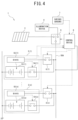
Figure 4] Figure 4 is a block diagram illustrating an outline of electrical connection of the solar streetlight according to the example of the present invention. - An electric storage device according to an embodiment of the present invention is characterized by including: a plurality of battery packs capable of supplying electricity to a predetermined load, and installed to align in an up-down direction inside a columnar member; a control device that is arranged above the battery packs and controls the battery packs; a submersion sensor provided in each of the plurality of battery packs; and a notification unit that gives notification of information regarding immersion to the outside, in which the control device includes a communication unit that receives information indicating submersion from the submersion sensor in each battery pack, a determination unit that determines a degree of immersion on a basis of which of the submersion sensors having transmitted the received information indicating submersion, and a control unit that controls the notification unit to give notification of immersion degree information indicating the degree of immersion determined by the determination unit to the outside. With this configuration, the electric storage device according to the embodiment of the present invention can give notification of immersion information to the outside.
- Hereinafter, an electric storage device according to an example of the present invention will be described with reference to the drawings.
- As illustrated in
Figure 1 , the present example is described by using an electric storage device used for a solar streetlight installed outside as an example. - A
solar streetlight 1 as a streetlight includes acolumnar member 2, asolar panel 3, anillumination device 4 as a predetermined load, a plurality ofbattery packs 5, and acontrol device 6. Thesolar streetlight 1 is installed on a ground G. - Hereinafter, based on the
columnar member 2, theillumination device 4 side is defined as "front," the opposite side thereof is defined as "back," when viewing the front side from the back side, the left side is defined as "left," the right side is defined as "right," and the upper side is defined as "up." Of the side surfaces of thecolumnar member 2, a side surface on which theillumination device 4 is installed is the front side of thesolar streetlight 1. - The
columnar member 2 is formed of a square pole, and is formed in a hollow shape having a space on the inside. Thecolumnar member 2 can also adopt shapes other than the square pole, such as a prism or a cylinder. As will be described later, a plurality ofbattery packs 5 capable of supplying electricity to theillumination device 4 and thecontrol device 6 are installed inside thecolumnar member 2. - The
control device 6 is disposed above the plurality ofbattery packs 5 inside thecolumnar member 2. A first opening 21 and a second opening 22 located above the first opening 21 are formed on aside surface 2a on the front side of thecolumnar member 2. - The
first opening 21 is provided in the installation position of the plurality ofbattery packs 5. Thefirst opening 21 is used when performing work such as replacing thebattery pack 5 and performing maintenance, for example, and is closed by alid 21a when the work is not performed. - The
second opening 22 is provided in the installation position of thecontrol device 6. Thesecond opening 22 is used when operating thecontrol device 6 or performing maintenance work, for example, and is closed by alid 22a when the operation and work are not performed. - In the present example, the installation area of the plurality of
battery packs 5 inside thecolumnar member 2 is longer than the installation area of thecontrol device 6 in the height direction of thecolumnar member 2, and therefore thefirst opening 21 is longer than the second opening 22 in the height direction. - A
drainpipe 25 embedded below the ground G is connected to a bottom part of thecolumnar member 2. Thedrainpipe 25 is a pipe for draining moist that pools in the bottom part of thecolumnar member 2 to the underground as wastewater. - The
solar panel 3 is attached to atop 23 of thecolumnar member 2. Thesolar panel 3 is formed of a photovoltaic module that generates electricity using optical energy from the sun, and is adjusted according to the installation location of thesolar streetlight 1, so that thesolar panel 3 is oriented to obtain the maximum amount of solar radiation throughout the year. Thesolar panel 3 is connected to thebattery pack 5 and thecontrol device 6 to be able to supply electricity thereto. - The
illumination device 4 is disposed in an upper part of theside surface 2a on the front side of thecolumnar member 2, and shines a downward light from an upper part of thecolumnar member 2. - The
battery pack 5 is a reused vehicle battery pack that had been mounted on a vehicle. In the present example, in order to reuse battery packs with a small capacity used in hybrid vehicles, a plurality ofbattery packs 5 are combined to increase the capacity for use. - In the case of reused
battery packs 5, performance varies due to different capacities and degrees of deterioration in internal resistance and the like depending on the usage history. Since the remaining life differs among the plurality of combinedbattery packs 5, there is a high possibility that thebattery pack 5 will need to be replaced during use. In the present example, by arranging the plurality ofbattery packs 5 inside thecolumnar member 2 as described above, even when an anomaly occurs in somebattery packs 5, operation as a streetlight can be assured by theremaining battery packs 5. - The
battery pack 5 is formed in a rectangular parallelepiped shape in which a side in the vertical direction is shorter than a side in the horizontal direction when placed in the transverse direction. "Placed in the transverse direction" refers to how thebattery pack 5 is placed when mounted on a vehicle, and is how thebattery pack 5 is placed so that its thickness is minimized. - In the present example, the
battery pack 5 is mounted so as to be placed in the vertical direction inside thecolumnar member 2. Moreover, in the present example, the vertically placed plurality ofbattery packs 5 are arranged to align in the up-down direction inside thecolumnar member 2. - The plurality of
battery packs 5 arranged in the up-down direction inside thecolumnar member 2 form a battery pack group. In the present example, fivebattery packs 5 arranged in the up-down direction form one battery pack group. The number of battery packs 5 included in a battery pack group is arbitrary, and is not limited to five. - Moreover, in the present example, two rows of the battery pack groups are provided inside the
columnar member 2. Of the two rows of battery pack groups, one is referred to as abattery pack group 5A, and the other is referred to as abattery pack group 5B. The number of rows of the battery pack groups provided inside thecolumnar member 2 is not limited to two, and may be one, or three or more, for example. - The battery packs 5 of the same battery pack group are connected to the same wiring. Specifically, the five
battery packs 5 included in thebattery pack group 5A are connected to wiring 50A, and the fivebattery packs 5 included in thebattery pack group 5B are connected to wiring 50B. - The
wiring 50A and thewiring 50B are routed in the up-down direction inside thecolumnar member 2. - A
positive terminal 60 and apower supply terminal 63 described later of eachbattery pack 5, thesolar panel 3, theillumination device 4, thecontrol device 6, and the like of the corresponding battery pack group are connected to each of thewiring 50A and thewiring 50B. - The
battery pack group 5A and thebattery pack group 5B form different battery pack group systems, and can function independently. For this reason, even when a trouble occurs in one system, the battery pack can be operated by the other system in which no trouble has occurred. - The
control device 6 is connected to a battery management system (BMS) 55 (seeFigure 2 ) described later in thebattery pack 5, and controls the plurality ofbattery packs 5 via theBMS 55. Thecontrol device 6 exchanges information with theBMS 55 through communication. - The
control device 6 is formed of a computer unit including a central processing unit (CPU), a random access memory (RAM), a read only memory (ROM), an input port, and an output port. A program for causing the computer unit to function as thecontrol device 6 is stored, together with various constants and the like, in the ROM of the computer unit. That is, the CPU executing the program stored in the ROM by using the RAM as a work area causes the computer unit to function as thecontrol device 6 of the present example. - Various sensors 7 (see
Figure 4 ) are connected to thecontrol device 6. For example, sensors capable of detecting a change in the external environment such as an illumination sensor are connected to thecontrol device 6. Thecontrol device 6 may include a timer that manages the lighting duration and lighting time. A configuration of thecontrol device 6 will be described in detail later. - Next, the electric configuration of the
battery pack 5 of the present example will be described with reference toFigure 2 . - As illustrated in
Figure 2 , thebattery pack 5 includes abattery 53, arelay 54, aBMS 55, and asubmersion sensor 56. Thebattery 53, therelay 54, theBMS 55, and thesubmersion sensor 56 are provided inside thebattery pack 5. - The
battery 53 is formed of a chargeable and dischargeable secondary battery such as a lithium ion battery. Thebattery 53 has apositive electrode 53a and anegative electrode 53b. - The
positive electrode 53a of thebattery 53 is connected to thepositive terminal 60 via therelay 54 so as to be electrically conductive. Thepositive terminal 60 is a terminal that outputs the voltage of thebattery 53 to the outside of thebattery pack 5, and is exposed to the outside of thebattery pack 5. Thenegative electrode 53b of thebattery 53 is connected to a case of thebattery pack 5 via aground terminal 61. - The
relay 54 is a switch that is provided between thepositive electrode 53a of thebattery 53 and thepositive terminal 60, and is capable of switching between a connected state in which thepositive electrode 53a of thebattery 53 and thepositive terminal 60 are connected and a disconnected state in which the two are disconnected. - The
relay 54 is switched to the disconnected state when submersion of thebattery pack 5 is detected by thesubmersion sensor 56. - The
BMS 55 monitors and manages states of thebattery 53 such as the voltage value and the state of charge (SOC) of thebattery 53. TheBMS 55 calculates the SOC on the basis of the charging and discharging current of thebattery 53. TheBMS 55 controls switching between the connected state and disconnected state of therelay 54. - The
BMS 55 is connected to thecontrol device 6 through acommunication terminal 62 provided in thebattery pack 5. TheBMS 55 is connected to the power supply via thepower supply terminal 63 and a powersupply GND terminal 64 provided in thebattery pack 5. In the present example, thebattery 53 and thesolar panel 3 are used as the power supply. - The
submersion sensor 56 is a sensor that detects submersion of thebattery pack 5. Various submersion sensors such as a sensor that detects submersion by sensing hydraulic pressure of a predetermined pressure or greater indicating submersion, a sensor that detects submersion when positive and negative terminals are submerged in water and there is continuity between the terminals, or the like can be used as thesubmersion sensor 56. - Here, the
battery pack 5 is installed in the vertical direction inside thecolumnar member 2 to be oriented so that thepositive terminal 60 is located above thesubmersion sensor 56. As a result, thepositive terminal 60 is located above thesubmersion sensor 56. - Next, a configuration of the
control device 6 of the present example will be described with reference toFigure 3 . - As illustrated in
Figure 3 , thecontrol device 6 has a function as acommunication unit 71 that receives information indicating submersion from thesubmersion sensor 56 in eachbattery pack 5. Thecontrol device 6 has a function as adetermination unit 72 that determines the degree of immersion on the basis of which of thesubmersion sensors 56 in the battery packs 5 having transmitted the received information indicating submersion. - Here, the ROM of the
control device 6 stores, for eachbattery pack 5, the height from the ground G to the installation position of thebattery pack 5 as height information. Thecontrol device 6 can identify thebattery pack 5 including thesubmersion sensor 56 from which the information indicating submersion has been received, and determine the degree of immersion by referring to the height information of the identifiedbattery pack 5. That is, thecontrol device 6 can determine up to what height (how many meters) thesolar streetlight 1 is immersed in water. - The
control device 6 has a function as acontrol unit 73 that controls anotification unit 80 described later to give notification of immersion degree information indicating the degree of immersion determined by thedetermination unit 72 to the outside. Immersion degree information is information indicating the immersion height of thesolar streetlight 1 in its installation location. - The
notification unit 80 that gives notification of information regarding immersion to the outside is connected to thecontrol device 6. Thenotification unit 80 is formed of an analog, digital, or another-type indicator, and is provided on an outer surface of thecolumnar member 2. With this configuration, thecontrol device 6 can display the immersion height of thesolar streetlight 1 in its installation location on the indicator. - The outer surface of the
columnar member 2 on which thenotification unit 80 is provided is preferably theside surface 2a on the front side of thecolumnar member 2, for example. In this case, in order for thenotification unit 80 to give notification to a wider area, it is desirable that thenotification unit 80 be provided in an upper part of theside surface 2a on the front side of thecolumnar member 2. - Next, the electrical connection of the
solar streetlight 1 of the present example will be described with reference toFigure 4 . - As illustrated in
Figure 4 , one to n (n = 5 in present example) battery packs 5 are provided in thesolar streetlight 1 according to the present example. In the present example, in order to distinguish among the plurality of battery packs 5, the plurality ofbattery packs 5 are denoted by battery packs 5(1) to 5(n). When referring to one battery pack without specifying which of the battery packs 5(1) to 5(n), the battery pack is simply referred to as the "battery pack 5." - In
Figure 4 , thebattery pack 5 of thebattery pack group 5A connected to thewiring 50A is illustrated as an example of the battery packs 5(1) to 5(n). Hence, thewiring 50B and thebattery pack group 5B are omitted fromFigure 4 . - The battery packs 5(1) to 5(n) are connected in parallel to each other with respect to the
wiring 50A. - In the present example, to identify which of the battery packs 5(1) to 5(n) the
battery 53, therelay 54, and theBMS 55 belong to, thebatteries 53, therelays 54, and theBMSs 55 corresponding to the battery packs 5(1) to 5(n) are denoted by batteries 53(1) to 53(n), relays 54(1) to 54(n), and BMSs 55(1) to 55(n). Regarding the batteries 53(1) to 53(n), the relays 54(1) to 54(n), and the BMSs 55(1) to 55(n), when referring to one battery, relay, and BMS without specifying which of the battery packs 5(1) to 5(n) the components belong to, the components are simply referred to as the "battery 53," the "relay 54," and the "BMS 55." - A
first switch 8 capable of switching between an ON state in which theBMS 55 and thewiring 50A are connected and an OFF state in which the two are disconnected is provided between theBMS 55 and thewiring 50A. At least onefirst switch 8 is provided for eachBMS 55. While the present example describes an example in which onefirst switch 8 is provided for eachBMS 55, two or morefirst switches 8 may be provided for eachBMS 55. - In the present example, to identify which of the BMSs 55(1) to 55(n) the
first switch 8 belongs to, thefirst switches 8 corresponding to the BMSs 55(1) to 55(n) are denoted by first switches 8(1) to 8(n). Regarding the first switches 8(1) to 8(n), when referring to one switch without specifying which of the BMSs 55(1) to 55(n) the switch belongs to, the switch is simply referred to as the "first switch 8." - The
control device 6 controls the switching between the ON state and the OFF state of thefirst switch 8. - A
second switch 9 is connected to one end of thewiring 50A. Thesecond switch 9 is a switch that is provided between thewiring 50A, and thesolar panel 3 andillumination device 4, and is capable of switching between an ON state in which thewiring 50A and thesolar panel 3 orillumination device 4 are connected and an OFF state in which the two are disconnected. - That is, the
second switch 9 is capable of switching between an ON state which is either a power generation-ON state connecting thewiring 50A and thesolar panel 3 or a discharge-ON state connecting thewiring 50A and theillumination device 4, and an OFF state not connecting thewiring 50A with any of thesolar panel 3 and theillumination device 4. - The
control device 6 controls the switching between the power generation-ON state or discharge-ON state and the OFF state of thesecond switch 9. In a state where the power of thecontrol device 6 is not turned on, such as at the time of initial startup of thesolar streetlight 1, from the viewpoint of ensuring electricity for starting thesolar streetlight 1, it is preferable that thesecond switch 9 be switched to the power generation-ON state. - The
control device 6 is connected to thewiring 50A, and receives supply of electricity from at least one of thesolar panel 3 and the battery packs 5(1) to 5(n) via thewiring 50A. Thecontrol device 6 controls switching between the ON state and the OFF state of thefirst switch 8 and thesecond switch 9. - In the present example, the battery packs 5 are arranged from top to bottom in the order of the battery packs 5(1) to 5(n) inside the
columnar member 2. Thefirst switch 8 is arranged above therelay 54. - Next, an operation of the
solar streetlight 1 when an installation location of thesolar streetlight 1 is flooded will be described. In thesolar streetlight 1 configured as described above, when an installation location of thesolar streetlight 1 is flooded, the following operation is performed. - For example, when the
submersion sensor 56 of the battery pack 5(n) detects submersion in a state where the battery pack 5(n) is supplying electricity, the first switch 8(n-1) of the battery pack 5(n-1) arranged immediately above the battery pack 5(n) is switched to the ON state. - After the first switch 8(n-1) is switched to the ON state, the relay 54(n-1) is switched to the connected state. Thereafter, the relay 54(n) of the battery pack 5(n) is switched to the disconnected state.
- When the relay 54(n) is switched to the disconnected state, the first switch 8(n) is switched to the OFF state.
- By operating the
solar streetlight 1 in the above procedure, it is possible to prevent interruption of the electricity supply from thebattery pack 5. Additionally, even when somebattery packs 5 are submerged in water, the remaining battery packs 5 can be used to continue lighting by theillumination device 4. - The
control device 6 is installed above the uppermost battery pack 5(1), and therefore can maintain the electricity supply from thebattery pack 5 and continue lighting by theillumination device 4 until all of the battery packs 5 are submerged in water. - Additionally, as described above, when the installation location of the
solar streetlight 1 is flooded, thesubmersion sensors 56 in the battery packs 5 are sequentially activated from thelowermost battery pack 5 to theuppermost battery pack 5 installed inside thecolumnar member 2. - In this case, as described above, since the
control device 6 is installed above thebattery pack 5, thecontrol device 6 is able to operate as long as thecontrol device 6 is not submerged in water even when all the battery packs 5 are submerged in water. Accordingly, thecontrol device 6 can grasp whether or not all of the battery packs 5 are submerged in water. - On the basis of height information of the
battery pack 5 from which information indicating submersion is received, thecontrol device 6 determines up to what height (how many meters) thesolar streetlight 1 is immersed in water, and gives notification of immersion degree information to the outside via thenotification unit 80. - When receiving information indicating submersion from the
submersion sensor 56 of acertain battery pack 5 among the plurality ofbattery packs 5 belonging to the same battery pack group, if information indicating submersion is not received from thesubmersion sensor 56 of thebattery pack 5 lower than thebattery pack 5 that has detected submersion, thecontrol device 6 determines that an anomaly has occurred in thesubmersion sensor 56 that has transmitted the information indicating submersion. - Note that the
control device 6 may determine whether thesubmersion sensor 56 having transmitted the information indicating submersion is normal or abnormal by a majority rule regarding the state of reception fromsubmersion sensors 56 including thesubmersion sensors 56 of the battery packs 5 lower than thebattery pack 5 that has detected submersion. - When receiving information indicating submersion from the
submersion sensor 56 of acertain battery pack 5 belonging to one battery pack group among a plurality of battery pack groups, if no information indicating submersion has been received from thebattery pack 5 belonging to another battery pack group at the same height as thebattery pack 5 that has detected submersion, thecontrol device 6 determines that an anomaly has occurred in thesubmersion sensor 56 that has transmitted the information indicating submersion. - Note that the
control device 6 may determine whether thesubmersion sensor 56 having transmitted the information indicating submersion is normal or abnormal by a majority rule regarding the state of reception fromsubmersion sensors 56 including thesubmersion sensors 56 of the battery packs 5 at the same height as thebattery pack 5 that has detected submersion but belonging to another battery pack group. - As has been described, in the electric storage device according to the present example, the
control device 6 determines the degree of immersion on the basis of whichsubmersion sensor 56 has transmitted information indicating submersion, and controls thenotification unit 80 to give notification of immersion degree information indicating the determined immersion degree to the outside. Thus, the electric storage device can give notification of immersion information to the outside. - In the electric storage device according to the present example, since the
notification unit 80 is an indicator provided on theside surface 2a on the front side of thecolumnar member 2, it is possible to give notification of the immersion degree information to the outside, such as to the periphery of thesolar streetlight 1, by thesolar streetlight 1 alone. For this reason, it is possible to warn a driver of a vehicle present in the periphery of thesolar streetlight 1 not to enter an area near the flooded installation location of thesolar streetlight 1. - Note that while the
notification unit 80 is formed of an indicator in the present example, the invention is not limited thereto, and thenotification unit 80 may be formed of theillumination device 4. In this case, it is possible to notify a driver of a vehicle present in the periphery of thesolar streetlight 1 of the flooded state by a blinking pattern or blinking cycle of theillumination device 4. For example, thecontrol device 6 shortens the blinking cycle whenmany battery packs 5 have detected submersion. Alternatively, at the time of a flood, theillumination device 4 may be lit in a color other than the illumination color used as lighting at times other than a flood. Moreover, a red light, for example, may be provided in theillumination device 4, and the red light may be lit to give notification of the flooded state. By forming thenotification unit 80 by theillumination device 4 as described above, immersion degree information can be notified using theillumination device 4, so that no separate indicator is required, and the configuration can be simplified. - Alternatively, the
notification unit 80 may be formed of a communication device that transmits immersion degree information to the outside. In this case, it is possible to notify a facility that needs to monitor the flooded state from a location away thesolar streetlight 1 of the flooded state around the installation location of thesolar streetlight 1, and promptly report the flooded state to the local government or the like. The local government or the like can promptly take necessary measures against the flood. - Alternatively, the
notification unit 80 may have, in addition to an indicator, a function as a communication device that transmits immersion degree information to the outside. In this case, it is possible to also give notification of the flooded state to areas other than the periphery of thesolar streetlight 1. - While the present example describes a case in which the electric storage device according to the present invention is applied to the
solar streetlight 1 using thesolar panel 3 as the power plant, the present invention is not limited thereto. For example, the electric storage device according to the present invention may be applied to a streetlight including an aerogenerator as the power plant. - While an example of the present invention has been disclosed, changes can be made without departing from the scope of the present invention by a person skilled in the art, as a matter of course. All of such modifications and the equivalents are intended to be included in the following claims.
-
- 1
- solar streetlight (streetlight)
- 2
- columnar member
- 2a
- side surface (outer surface)
- 3
- solar panel
- 4
- illumination device (predetermined load)
- 5
- battery pack
- 5A, 5B
- battery pack group
- 6
- control device
- 21
- first opening
- 22
- second opening
- 23
- top
- 25
- drainpipe
- 50A, 50B
- wiring
- 53
- battery
- 53a
- positive electrode
- 53b
- negative electrode
- 54
- relay
- 55
- BMS
- 56
- submersion sensor
- 60
- positive terminal
- 61
- ground terminal
- 71
- communication unit
- 72
- determination unit
- 73
- control unit
- 80
- notification unit
- G
- ground
Claims (6)
- An electric storage device comprising:a plurality of battery packs (5) capable of supplying electricity to a predetermined load (4), and installed to align in an up-down direction inside a columnar member (2);a control device (6) that is arranged above the battery packs (5) and controls the battery packs (5);a submersion sensor (56) provided in each of the plurality of battery packs (5); anda notification unit (80) that gives notification of information regarding immersion to the outside, the electric storage device being characterized in thatthe control device (6) includesa communication unit (71) that receives information indicating submersion from the submersion sensor (56) in each battery pack (5),a determination unit (72) that determines a degree of immersion on a basis of which of the submersion sensors (56) having transmitted the received information indicating submersion, anda control unit (73) that controls the notification unit (80) to give notification of immersion degree information indicating the degree of immersion determined by the determination unit (72) to the outside.
- The electric storage device as claimed in claim 1, wherein
The notification unit (80) is an indicator provided on an outer surface (2a) of the columnar member (2). - The electric storage device as claimed in claim 2, whereinthe electric storage device is used for a streetlight (1) in which the predetermined load (4) is an illumination device (4), andthe indicator is formed of the illumination device (4).
- The electric storage device as claimed in claim 1, wherein
the notification unit (80) is formed of a communication device that transmits the immersion degree information to the outside. - The electric storage device as claimed in claim 2 or 3, wherein
the notification unit (80) has, in addition to the indicator, a function as a communication device that transmits the immersion degree information to the outside. - The electric storage device as claimed in any one of claims 1 to 5, wherein
the battery pack (5) is a reused on-vehicle battery pack.
Applications Claiming Priority (1)
| Application Number | Priority Date | Filing Date | Title |
|---|---|---|---|
| JP2022014369A JP7310948B1 (en) | 2022-02-01 | 2022-02-01 | power storage device |
Publications (2)
| Publication Number | Publication Date |
|---|---|
| EP4220791A1 true EP4220791A1 (en) | 2023-08-02 |
| EP4220791B1 EP4220791B1 (en) | 2025-07-02 |
Family
ID=84537022
Family Applications (1)
| Application Number | Title | Priority Date | Filing Date |
|---|---|---|---|
| EP22213644.2A Active EP4220791B1 (en) | 2022-02-01 | 2022-12-14 | Electric storage device |
Country Status (2)
| Country | Link |
|---|---|
| EP (1) | EP4220791B1 (en) |
| JP (1) | JP7310948B1 (en) |
Citations (5)
| Publication number | Priority date | Publication date | Assignee | Title |
|---|---|---|---|---|
| KR20120117477A (en) * | 2011-04-15 | 2012-10-24 | 주식회사 엘지화학 | Apparatus for protecting battery pack and battery pack using the same |
| CN204648038U (en) * | 2015-04-21 | 2015-09-16 | 浙江警安科技有限公司 | Streetlight monitoring device |
| WO2017029715A1 (en) | 2015-08-19 | 2017-02-23 | 三菱電機株式会社 | Storage battery control device, electricity storage system, and solar power generation system |
| CN206422112U (en) * | 2016-12-08 | 2017-08-18 | 湖南小步科技有限公司 | A kind of water-tight device of battery bag air cooling system |
| CN111525069A (en) * | 2020-05-27 | 2020-08-11 | 国网新疆电力有限公司信息通信公司 | Multifunctional storage battery cabinet |
Family Cites Families (3)
| Publication number | Priority date | Publication date | Assignee | Title |
|---|---|---|---|---|
| US10094525B2 (en) * | 2013-11-08 | 2018-10-09 | Philips Lighting Holding B.V. | Battery powered lighting system |
| JP7154599B2 (en) * | 2019-09-04 | 2022-10-18 | 株式会社サンポール | bollard device |
| JP7335477B2 (en) * | 2020-03-10 | 2023-08-30 | 株式会社オーエスエム | POLE TYPE SOLAR GENERATOR, LIGHTING DEVICE INCLUDING THE POLE TYPE SOLAR GENERATOR, AND MONITORING INFORMATION COMMUNICATION DEVICE INCLUDING THE POLE TYPE SOLAR GENERATOR |
-
2022
- 2022-02-01 JP JP2022014369A patent/JP7310948B1/en active Active
- 2022-12-14 EP EP22213644.2A patent/EP4220791B1/en active Active
Patent Citations (5)
| Publication number | Priority date | Publication date | Assignee | Title |
|---|---|---|---|---|
| KR20120117477A (en) * | 2011-04-15 | 2012-10-24 | 주식회사 엘지화학 | Apparatus for protecting battery pack and battery pack using the same |
| CN204648038U (en) * | 2015-04-21 | 2015-09-16 | 浙江警安科技有限公司 | Streetlight monitoring device |
| WO2017029715A1 (en) | 2015-08-19 | 2017-02-23 | 三菱電機株式会社 | Storage battery control device, electricity storage system, and solar power generation system |
| CN206422112U (en) * | 2016-12-08 | 2017-08-18 | 湖南小步科技有限公司 | A kind of water-tight device of battery bag air cooling system |
| CN111525069A (en) * | 2020-05-27 | 2020-08-11 | 国网新疆电力有限公司信息通信公司 | Multifunctional storage battery cabinet |
Non-Patent Citations (1)
| Title |
|---|
| HUTT ROSAMOND: "This Dutch football stadium creates its own energy and stores it in electric car batteries | World Economic Forum", 6 July 2018 (2018-07-06), pages 1 - 13, XP093056253, Retrieved from the Internet <URL:https://www.weforum.org/agenda/2018/07/netherlands-football-johan-cruijff-stadium-electric-car-batteries/> [retrieved on 20230621] * |
Also Published As
| Publication number | Publication date |
|---|---|
| JP7310948B1 (en) | 2023-07-19 |
| JP2023112525A (en) | 2023-08-14 |
| EP4220791B1 (en) | 2025-07-02 |
Similar Documents
| Publication | Publication Date | Title |
|---|---|---|
| EP2161812A1 (en) | Power supply system, and power supply control method and power supply control program employed in power supply system | |
| US20130257440A1 (en) | Relay Welding Detector of Battery System and Battery System Which Uses the Detector | |
| CN103311965B (en) | Batteries in parallel connection group discharge and recharge intelligent management apapratus and method | |
| JP6198778B2 (en) | Variable disconnection device and variable disconnection control method for battery system | |
| JPWO2015040725A1 (en) | Battery system | |
| CN202633996U (en) | Intelligent management monitoring system of lithium battery pack | |
| KR101882466B1 (en) | Apparatus and method for controlling of battery energy storage system | |
| KR102628472B1 (en) | Energy storage system for using waste-battery and mobile house equipped with the same | |
| CN202455122U (en) | Device for intelligently managing charge-discharge of battery group in parallel | |
| RU2324263C2 (en) | Accumulator battery | |
| KR200455333Y1 (en) | Emergency power supply and battery monitoring integrated system | |
| KR101822928B1 (en) | Monitoring System for Energy Storage System | |
| EP4220791B1 (en) | Electric storage device | |
| EP4220793B1 (en) | Battery pack installation structure | |
| KR102536187B1 (en) | Distributed energy storage system for solar power plant and photovoltaic system using thereof | |
| EP4220007A1 (en) | Streetlight | |
| CN203406389U (en) | Battery pack parallel-connection control box of electric automobile | |
| KR101822919B1 (en) | Control apparatus for energy storage system and method thereof | |
| KR101008814B1 (en) | Solar cell power generation system | |
| CN102738533A (en) | Intelligent storage battery | |
| KR101868785B1 (en) | Pre-module control and relocation possible solar power system | |
| CN203103427U (en) | Lithium battery module structure for domestic consumption of solar excursion boat | |
| CN119765577A (en) | A battery safety monitoring system and method for a floating offshore wind farm booster station | |
| RU2795445C1 (en) | Traction battery based on lithium-iron-phosphate cells for unmanned highly automated vehicles | |
| KR101589194B1 (en) | Apparatus for variably disconnecting current flowing line in battery system and method thereof |
Legal Events
| Date | Code | Title | Description |
|---|---|---|---|
| PUAI | Public reference made under article 153(3) epc to a published international application that has entered the european phase |
Free format text: ORIGINAL CODE: 0009012 |
|
| STAA | Information on the status of an ep patent application or granted ep patent |
Free format text: STATUS: REQUEST FOR EXAMINATION WAS MADE |
|
| 17P | Request for examination filed |
Effective date: 20221214 |
|
| AK | Designated contracting states |
Kind code of ref document: A1 Designated state(s): AL AT BE BG CH CY CZ DE DK EE ES FI FR GB GR HR HU IE IS IT LI LT LU LV MC ME MK MT NL NO PL PT RO RS SE SI SK SM TR |
|
| STAA | Information on the status of an ep patent application or granted ep patent |
Free format text: STATUS: EXAMINATION IS IN PROGRESS |
|
| 17Q | First examination report despatched |
Effective date: 20240717 |
|
| GRAP | Despatch of communication of intention to grant a patent |
Free format text: ORIGINAL CODE: EPIDOSNIGR1 |
|
| STAA | Information on the status of an ep patent application or granted ep patent |
Free format text: STATUS: GRANT OF PATENT IS INTENDED |
|
| INTG | Intention to grant announced |
Effective date: 20250319 |
|
| GRAS | Grant fee paid |
Free format text: ORIGINAL CODE: EPIDOSNIGR3 |
|
| GRAA | (expected) grant |
Free format text: ORIGINAL CODE: 0009210 |
|
| STAA | Information on the status of an ep patent application or granted ep patent |
Free format text: STATUS: THE PATENT HAS BEEN GRANTED |
|
| AK | Designated contracting states |
Kind code of ref document: B1 Designated state(s): AL AT BE BG CH CY CZ DE DK EE ES FI FR GB GR HR HU IE IS IT LI LT LU LV MC ME MK MT NL NO PL PT RO RS SE SI SK SM TR |
|
| REG | Reference to a national code |
Ref country code: GB Ref legal event code: FG4D |
|
| REG | Reference to a national code |
Ref country code: CH Ref legal event code: EP |
|
| REG | Reference to a national code |
Ref country code: DE Ref legal event code: R096 Ref document number: 602022016826 Country of ref document: DE |
|
| REG | Reference to a national code |
Ref country code: IE Ref legal event code: FG4D |
|
| REG | Reference to a national code |
Ref country code: NL Ref legal event code: MP Effective date: 20250702 |
|
| PG25 | Lapsed in a contracting state [announced via postgrant information from national office to epo] |
Ref country code: PT Free format text: LAPSE BECAUSE OF FAILURE TO SUBMIT A TRANSLATION OF THE DESCRIPTION OR TO PAY THE FEE WITHIN THE PRESCRIBED TIME-LIMIT Effective date: 20251103 |
|
| PG25 | Lapsed in a contracting state [announced via postgrant information from national office to epo] |
Ref country code: NL Free format text: LAPSE BECAUSE OF FAILURE TO SUBMIT A TRANSLATION OF THE DESCRIPTION OR TO PAY THE FEE WITHIN THE PRESCRIBED TIME-LIMIT Effective date: 20250702 |
|
| REG | Reference to a national code |
Ref country code: AT Ref legal event code: MK05 Ref document number: 1810305 Country of ref document: AT Kind code of ref document: T Effective date: 20250702 |
|
| PG25 | Lapsed in a contracting state [announced via postgrant information from national office to epo] |
Ref country code: IS Free format text: LAPSE BECAUSE OF FAILURE TO SUBMIT A TRANSLATION OF THE DESCRIPTION OR TO PAY THE FEE WITHIN THE PRESCRIBED TIME-LIMIT Effective date: 20251102 |
|
| PG25 | Lapsed in a contracting state [announced via postgrant information from national office to epo] |
Ref country code: NO Free format text: LAPSE BECAUSE OF FAILURE TO SUBMIT A TRANSLATION OF THE DESCRIPTION OR TO PAY THE FEE WITHIN THE PRESCRIBED TIME-LIMIT Effective date: 20251002 |
|
| REG | Reference to a national code |
Ref country code: LT Ref legal event code: MG9D |
|
| PG25 | Lapsed in a contracting state [announced via postgrant information from national office to epo] |
Ref country code: AT Free format text: LAPSE BECAUSE OF FAILURE TO SUBMIT A TRANSLATION OF THE DESCRIPTION OR TO PAY THE FEE WITHIN THE PRESCRIBED TIME-LIMIT Effective date: 20250702 |
|
| PG25 | Lapsed in a contracting state [announced via postgrant information from national office to epo] |
Ref country code: FI Free format text: LAPSE BECAUSE OF FAILURE TO SUBMIT A TRANSLATION OF THE DESCRIPTION OR TO PAY THE FEE WITHIN THE PRESCRIBED TIME-LIMIT Effective date: 20250702 |
|
| PG25 | Lapsed in a contracting state [announced via postgrant information from national office to epo] |
Ref country code: HR Free format text: LAPSE BECAUSE OF FAILURE TO SUBMIT A TRANSLATION OF THE DESCRIPTION OR TO PAY THE FEE WITHIN THE PRESCRIBED TIME-LIMIT Effective date: 20250702 |
|
| PGFP | Annual fee paid to national office [announced via postgrant information from national office to epo] |
Ref country code: FR Payment date: 20251114 Year of fee payment: 4 |
|
| PG25 | Lapsed in a contracting state [announced via postgrant information from national office to epo] |
Ref country code: GR Free format text: LAPSE BECAUSE OF FAILURE TO SUBMIT A TRANSLATION OF THE DESCRIPTION OR TO PAY THE FEE WITHIN THE PRESCRIBED TIME-LIMIT Effective date: 20251003 |
|
| PG25 | Lapsed in a contracting state [announced via postgrant information from national office to epo] |
Ref country code: CZ Free format text: LAPSE BECAUSE OF FAILURE TO SUBMIT A TRANSLATION OF THE DESCRIPTION OR TO PAY THE FEE WITHIN THE PRESCRIBED TIME-LIMIT Effective date: 20250702 Ref country code: SE Free format text: LAPSE BECAUSE OF FAILURE TO SUBMIT A TRANSLATION OF THE DESCRIPTION OR TO PAY THE FEE WITHIN THE PRESCRIBED TIME-LIMIT Effective date: 20250702 |
|
| PG25 | Lapsed in a contracting state [announced via postgrant information from national office to epo] |
Ref country code: LV Free format text: LAPSE BECAUSE OF FAILURE TO SUBMIT A TRANSLATION OF THE DESCRIPTION OR TO PAY THE FEE WITHIN THE PRESCRIBED TIME-LIMIT Effective date: 20250702 |
|
| PG25 | Lapsed in a contracting state [announced via postgrant information from national office to epo] |
Ref country code: BG Free format text: LAPSE BECAUSE OF FAILURE TO SUBMIT A TRANSLATION OF THE DESCRIPTION OR TO PAY THE FEE WITHIN THE PRESCRIBED TIME-LIMIT Effective date: 20250702 Ref country code: PL Free format text: LAPSE BECAUSE OF FAILURE TO SUBMIT A TRANSLATION OF THE DESCRIPTION OR TO PAY THE FEE WITHIN THE PRESCRIBED TIME-LIMIT Effective date: 20250702 |
|
| PG25 | Lapsed in a contracting state [announced via postgrant information from national office to epo] |
Ref country code: RS Free format text: LAPSE BECAUSE OF FAILURE TO SUBMIT A TRANSLATION OF THE DESCRIPTION OR TO PAY THE FEE WITHIN THE PRESCRIBED TIME-LIMIT Effective date: 20251002 |
|
| PG25 | Lapsed in a contracting state [announced via postgrant information from national office to epo] |
Ref country code: ES Free format text: LAPSE BECAUSE OF FAILURE TO SUBMIT A TRANSLATION OF THE DESCRIPTION OR TO PAY THE FEE WITHIN THE PRESCRIBED TIME-LIMIT Effective date: 20250702 |
|
| PG25 | Lapsed in a contracting state [announced via postgrant information from national office to epo] |
Ref country code: RO Free format text: LAPSE BECAUSE OF FAILURE TO SUBMIT A TRANSLATION OF THE DESCRIPTION OR TO PAY THE FEE WITHIN THE PRESCRIBED TIME-LIMIT Effective date: 20250702 |
|
| PG25 | Lapsed in a contracting state [announced via postgrant information from national office to epo] |
Ref country code: SM Free format text: LAPSE BECAUSE OF FAILURE TO SUBMIT A TRANSLATION OF THE DESCRIPTION OR TO PAY THE FEE WITHIN THE PRESCRIBED TIME-LIMIT Effective date: 20250702 |
|
| PG25 | Lapsed in a contracting state [announced via postgrant information from national office to epo] |
Ref country code: DK Free format text: LAPSE BECAUSE OF FAILURE TO SUBMIT A TRANSLATION OF THE DESCRIPTION OR TO PAY THE FEE WITHIN THE PRESCRIBED TIME-LIMIT Effective date: 20250702 |
|
| PGFP | Annual fee paid to national office [announced via postgrant information from national office to epo] |
Ref country code: DE Payment date: 20251231 Year of fee payment: 4 |
|
| PG25 | Lapsed in a contracting state [announced via postgrant information from national office to epo] |
Ref country code: IT Free format text: LAPSE BECAUSE OF FAILURE TO SUBMIT A TRANSLATION OF THE DESCRIPTION OR TO PAY THE FEE WITHIN THE PRESCRIBED TIME-LIMIT Effective date: 20250702 |
|
| PG25 | Lapsed in a contracting state [announced via postgrant information from national office to epo] |
Ref country code: SK Free format text: LAPSE BECAUSE OF FAILURE TO SUBMIT A TRANSLATION OF THE DESCRIPTION OR TO PAY THE FEE WITHIN THE PRESCRIBED TIME-LIMIT Effective date: 20250702 Ref country code: EE Free format text: LAPSE BECAUSE OF FAILURE TO SUBMIT A TRANSLATION OF THE DESCRIPTION OR TO PAY THE FEE WITHIN THE PRESCRIBED TIME-LIMIT Effective date: 20250702 |