EP4220779A1 - Current collector and preparation method therefor, and secondary battery and apparatus - Google Patents
Current collector and preparation method therefor, and secondary battery and apparatus Download PDFInfo
- Publication number
- EP4220779A1 EP4220779A1 EP22778711.6A EP22778711A EP4220779A1 EP 4220779 A1 EP4220779 A1 EP 4220779A1 EP 22778711 A EP22778711 A EP 22778711A EP 4220779 A1 EP4220779 A1 EP 4220779A1
- Authority
- EP
- European Patent Office
- Prior art keywords
- current collector
- lithiophilic
- metal
- coated
- silver
- Prior art date
- Legal status (The legal status is an assumption and is not a legal conclusion. Google has not performed a legal analysis and makes no representation as to the accuracy of the status listed.)
- Pending
Links
Images

Classifications
-
- H—ELECTRICITY
- H01—ELECTRIC ELEMENTS
- H01M—PROCESSES OR MEANS, e.g. BATTERIES, FOR THE DIRECT CONVERSION OF CHEMICAL ENERGY INTO ELECTRICAL ENERGY
- H01M4/00—Electrodes
- H01M4/02—Electrodes composed of, or comprising, active material
- H01M4/64—Carriers or collectors
- H01M4/66—Selection of materials
- H01M4/661—Metal or alloys, e.g. alloy coatings
-
- H—ELECTRICITY
- H01—ELECTRIC ELEMENTS
- H01M—PROCESSES OR MEANS, e.g. BATTERIES, FOR THE DIRECT CONVERSION OF CHEMICAL ENERGY INTO ELECTRICAL ENERGY
- H01M4/00—Electrodes
- H01M4/02—Electrodes composed of, or comprising, active material
- H01M4/04—Processes of manufacture in general
- H01M4/0402—Methods of deposition of the material
- H01M4/0404—Methods of deposition of the material by coating on electrode collectors
-
- H—ELECTRICITY
- H01—ELECTRIC ELEMENTS
- H01M—PROCESSES OR MEANS, e.g. BATTERIES, FOR THE DIRECT CONVERSION OF CHEMICAL ENERGY INTO ELECTRICAL ENERGY
- H01M4/00—Electrodes
- H01M4/02—Electrodes composed of, or comprising, active material
- H01M4/64—Carriers or collectors
- H01M4/66—Selection of materials
- H01M4/665—Composites
- H01M4/667—Composites in the form of layers, e.g. coatings
-
- H—ELECTRICITY
- H01—ELECTRIC ELEMENTS
- H01M—PROCESSES OR MEANS, e.g. BATTERIES, FOR THE DIRECT CONVERSION OF CHEMICAL ENERGY INTO ELECTRICAL ENERGY
- H01M4/00—Electrodes
- H01M4/02—Electrodes composed of, or comprising, active material
- H01M4/64—Carriers or collectors
- H01M4/70—Carriers or collectors characterised by shape or form
-
- H—ELECTRICITY
- H01—ELECTRIC ELEMENTS
- H01M—PROCESSES OR MEANS, e.g. BATTERIES, FOR THE DIRECT CONVERSION OF CHEMICAL ENERGY INTO ELECTRICAL ENERGY
- H01M10/00—Secondary cells; Manufacture thereof
- H01M10/05—Accumulators with non-aqueous electrolyte
- H01M10/052—Li-accumulators
-
- H—ELECTRICITY
- H01—ELECTRIC ELEMENTS
- H01M—PROCESSES OR MEANS, e.g. BATTERIES, FOR THE DIRECT CONVERSION OF CHEMICAL ENERGY INTO ELECTRICAL ENERGY
- H01M4/00—Electrodes
- H01M4/02—Electrodes composed of, or comprising, active material
- H01M4/64—Carriers or collectors
- H01M4/66—Selection of materials
-
- Y—GENERAL TAGGING OF NEW TECHNOLOGICAL DEVELOPMENTS; GENERAL TAGGING OF CROSS-SECTIONAL TECHNOLOGIES SPANNING OVER SEVERAL SECTIONS OF THE IPC; TECHNICAL SUBJECTS COVERED BY FORMER USPC CROSS-REFERENCE ART COLLECTIONS [XRACs] AND DIGESTS
- Y02—TECHNOLOGIES OR APPLICATIONS FOR MITIGATION OR ADAPTATION AGAINST CLIMATE CHANGE
- Y02E—REDUCTION OF GREENHOUSE GAS [GHG] EMISSIONS, RELATED TO ENERGY GENERATION, TRANSMISSION OR DISTRIBUTION
- Y02E60/00—Enabling technologies; Technologies with a potential or indirect contribution to GHG emissions mitigation
- Y02E60/10—Energy storage using batteries
Definitions
- This application pertains to the field of batteries, and relates to a current collector and a preparation method thereof. This application further relates to a secondary battery containing such current collector, and an apparatus containing such secondary battery.
- Lithium metal has advantages such as extremely high theoretical specific capacity (3860 mAh•g -1 ), minimum reduction potential (-3.04 V vs. standard hydrogen electrode), minimum atomic radius, and low density (0.534 g•cm -3 ).
- Lithium metal has advantages such as extremely high theoretical specific capacity (3860 mAh•g -1 ), minimum reduction potential (-3.04 V vs. standard hydrogen electrode), minimum atomic radius, and low density (0.534 g•cm -3 ).
- lithium dendrites grow inevitably, causing huge safety risks in use of lithium metal batteries.
- metal current collectors with nanostructure or microstructure can provide more abundant sites for lithium precipitation, thereby suppressing the generation of lithium dendrites.
- lithiophilic current collectors can reduce nucleation of lithium precipitation, helping to reduce the energy barrier of lithium precipitation.
- this application aims to provide a current collector, a preparation method of current collector, a secondary battery containing such current collector, and an apparatus containing such secondary battery.
- the current collector can effectively suppress lithium dendrites when used in secondary batteries.
- a current collector including:
- a second aspect of this application provides a preparation method of current collector, including the following steps:
- a third aspect of this application provides a secondary battery, including the current collector according to the first aspect of this application or the preparation method of current collector according to the second aspect of this application.
- a fourth aspect of this application provides an apparatus, including the secondary battery according to the third aspect of this application.
- the metal current collector based on lithium metal battery of this application solves problems such as many generated lithium dendrites for current collectors.
- Silver microparticles whose internal structure is a cavity are used as an example. This material is made by using currently commercialized silver-coated copper microparticles as the raw material, and corroding the intermediate copper layer with an acid solution to form a cavity structure. Due to lithium affinity of the silver shell layer, lithium metal can be precipitated into the cavity structure during charge and discharge. As compared with silver coating, this method is not only simple to operate, but also can accurately limit the space for lithium precipitation, greatly suppressing the growth of lithium dendrites, thereby significantly improving cycling performance of batteries. In addition, as compared with ordinary three-dimensional current collectors, the closed space structure in the silver shell can effectively reduce electrolyte consumed during lithium precipitation, which is beneficial to the long-term operation of batteries.
- any lower limit may be combined with any upper limit to form a range not explicitly recorded, and any lower limit may be combined with another lower limit to form a range not explicitly recorded, and likewise, any upper limit may be combined with any other upper limit to form a range not explicitly recorded.
- each individually disclosed point or single numerical value as a lower limit or an upper limit, may be combined with any other point or single numerical value or combined with another lower limit or upper limit to form an unspecified range.
- the current collector according to the first aspect of this application is described first, including:
- the inventors have found through research that in the current collector of this application, due to the lithium affinity of the shell layer, lithium metal can be precipitated into the cavity structure during charge and discharge, thereby greatly suppressing the growth of lithium dendrites, and significantly improving the cycling performance of batteries.
- morphology of the external structure of the lithiophilic material is selected from one or more of granular structure, linear structure, plate structure, spherical shape, and near-spherical shape.
- FIG. 1 shows an example of an embodiment of a current collector according to this application, where an external structure of a lithiophilic material is a granular structure.
- FIG. 2 shows an example of a schematic diagram of an embodiment of a current collector according to this application, where an external structure of a lithiophilic material is a linear structure.
- Embodiments of the current collector according to this application are not limited thereto.
- the foregoing external structure may be a nano-scale structure or a micro-scale structure.
- selecting the foregoing structure can increase a specific surface area of the lithiophilic material. This can increase sites for active reaction during lithium precipitation, and reduce current density, thereby facilitating uniform distribution of electrons, and improving uniformity of lithium precipitation.
- an average thickness of the external structure of the lithiophilic material is 0.05-2 ⁇ m, and preferably 0.1-1 ⁇ m.
- the average thickness of the external structure refers to an average value of multiple thicknesses of the external structure, for example, 0.05 ⁇ m, 0.07 ⁇ m, 0.1 ⁇ m, 0.3 ⁇ m, 0.5 ⁇ m, 0.7 ⁇ m, 1 ⁇ m, 1.3 ⁇ m, 1.5 ⁇ m, 1.7 ⁇ m, 2 ⁇ m, and any value therebetween.
- the average thickness of the external structure falling within the range defined in this application can help the lithiophilic material to maintain a stable cavity structure, and allow diffusion of lithium ions into the internal cavity through the external structure so that lithium ions are precipitated in the internal cavity structures.
- a material of the external structure of the lithiophilic material is metal and/or metal oxide with lithium affinity, and preferably selected from one or more of gold, silver, platinum, and silver oxide.
- a material of the external structure of the current collector may be a product of reaction between one or more of silver-coated tin powder, silver-coated zinc powder, silver-coated iron powder, silver-coated aluminum powder, silver-coated copper powder, gold-coated tin powder, gold-coated zinc powder, gold-coated iron powder, gold-coated aluminum powder, gold-coated copper powder, platinum-coated tin powder, platinum-coated zinc powder, platinum-coated iron powder, platinum-coated aluminum powder, and platinum-coated copper powder and an acid solution (sulfuric acid and/or hydrochloric acid).
- the material of the external structure of the lithiophilic material has good oxidation resistance so as not to react with the acid solution during acid treatment, maintaining the stability
- the thickness of the lithiophilic layer is 1-500 ⁇ m, and preferably 10-100 ⁇ m.
- the thickness of the lithiophilic layer is an overall thickness of the outer lithiophilic layer, for example, 1 ⁇ m, 10 ⁇ m, 50 ⁇ m, 100 ⁇ m, 200 ⁇ m, 300 ⁇ m, 400 ⁇ m, 500 ⁇ m, and any value therebetween.
- the thickness of the lithiophilic layer falling within the range defined in this application, all lithium ions transported from a positive electrode can be accommodated, and lithium ions are precipitated in the cavity structure of the lithiophilic material, thereby effectively suppressing battery volume change caused by lithium precipitation.
- An appropriate thickness of the lithiophilic layer can reduce adverse effects on mass energy density and volumetric energy density.
- the current collector body is metal foil, and preferably copper foil.
- this application provides a preparation method of current collector, including the following steps:
- the preparation method in this application is simple to operate, and can accurately limit the space for lithium precipitation, greatly suppressing the growth of lithium dendrites, thereby significantly improving cycling performance of batteries.
- the metal A is selected from one or more of tin, zinc, iron, aluminum, and copper.
- the selected metal A has low oxidation resistance, and undergoes oxidation-reduction reaction with an acid solution during acid treatment to form an internal cavity structure.
- the metal B is one or more of gold, silver, and platinum.
- the selected metal B has high oxidation resistance so as not to react with an acid solution during acid treatment, thereby maintaining the stability of the external structure.
- the material with a composite structure is one or more of silver-coated tin powder, silver-coated zinc powder, silver-coated iron powder, silver-coated aluminum powder, silver-coated copper powder, gold-coated tin powder, gold-coated zinc powder, gold-coated iron powder, gold-coated aluminum powder, gold-coated copper powder, platinum-coated tin powder, platinum-coated zinc powder, platinum-coated iron powder, platinum-coated aluminum powder, and platinum-coated copper powder.
- the selected material with a composite structure can selectively dissolve an internal material with low oxidation resistance through acid treatment, while maintaining a stable external structure, thereby forming a lithiophilic material with an internal cavity structure.
- amount of the metal B is 1wt% to 10wt%. for example, 1wt%, 2wt%, 3wt%, 4wt%, 5wt%, 6wt%, 7wt%, 8wt%, 9wt%, 10wt%, and any value therebetween.
- the amount of the metal B needs to be high enough to maintain the stability of the lithiophilic material with a cavity structure, and also needs to be controlled not to be too high because a too high amount suppresses the formation of the internal cavity structure, and such suppressing does not help achieve the purpose of lithium precipitation in the cavity structure.
- potential of the acid solution is between potentials of the internal structure and the external structure, and preferably selected from sulfuric acid and/or hydrochloric acid.
- a proper solution such as concentrated sulfuric acid is used to corrode the raw material.
- the potential of the solute in the solution is between potentials of the inner and outer layers of the raw material, so that the solution reacts only with the inner layer of the raw material but not the outer layer, forming a lithiophilic layer whose internal structure is a cavity.
- the external structure of the material with a composite structure has nano-scale pores for lithium ions and/or hydrogen ions to pass through the external structure and enter the internal structure.
- the applying method in step (3) includes mixing the multiple lithiophilic materials with a dispersion liquid, and applying the mixture on the surface of the current collector body to form the lithiophilic layer on the surface of the current collector body.
- the number of multiple lithiophilic materials is not particularly limited provided that the lithiophilic layer has the desired thickness.
- the dispersion liquid includes but is not limited to water, ethanol, ethylene glycol, N-methylpyrrolidone, and N,N-dimethylformamide.
- the dispersion liquid may be a mixture of one or more of the foregoing substances.
- a weight ratio of the current collector and the dispersion liquid has a wide selection range, provided that the resulting mixture can be evenly applied on the surface of the current collector body.
- the coating method includes but is not limited to pulling method, film drawing method, electrostatic spraying method, spin coating method, and the like.
- the pulling method, film drawing method, electrostatic spraying method, and spin coating method may be conventional operations in the field, and details are not repeated herein.
- the method further includes drying after step (3), and preferably conditions for the drying include: temperature being 70°C-90°C, and time being 1 h-4 h.
- this application provides a secondary battery, including the current collector according to the first aspect of this application or the preparation method of current collector according to the second aspect of this application.
- active ions are intercalated and deintercalated between a positive electrode plate and a negative electrode plate.
- the electrolyte conducts ions between the positive electrode plate and the negative electrode plate.
- the battery is an alkali metal battery, and preferably a lithium metal battery, a potassium metal battery, or a sodium metal battery.
- the secondary battery further includes a positive electrode, a negative electrode, an electrolyte, and a separator.
- the negative electrode includes but is not limited to lithium metal, potassium metal, or sodium metal.
- the positive electrode includes but is not limited to lithium iron phosphate, lithium cobaltate, lithium titanate, lithium nickel cobalt manganese oxide, and the like.
- the electrolyte conducts ions between the positive electrode plate and the negative electrode plate.
- the electrolyte is not specifically limited to any particular type in this application, and may be selected based on a need.
- the electrolyte may be selected from at least one of a solid electrolyte and a liquid electrolyte (that is, an electrolyte solution).
- the electrolyte is an electrolyte solution.
- the electrolyte solution includes an electrolytic salt and a solvent.
- the electrolytic salt may be one or more of lithium hexafluorophosphate (LiPF 6 ), lithium tetrafluoroborate (LiBF 4 ), lithium perchlorate (LiClO 4 ), lithium hexafluoroarsenate (LiAsF 6 ), lithium bis(fluorosulfonyl)imide (LiFSI), lithium bistrifluoromethanesulfonimide (LiTFSI), lithium trifluoromethanesulfonate (LiTFS), lithium difluoro(oxalato)borate (LiDFOB), lithium dioxalate borate (LiBOB), lithium difluorophosphate (LiPO 2 F 2 ), lithium difluoro(dioxalato)phosphate (LiDFOP), and lithium tetrafluoro oxalato phosphate (LiTFOP).
- LiPF 6 lithium hexafluorophosphate
- LiBF 4 lithium per
- the solvent may be selected from one or more of ethylene carbonate (EC), propylene carbonate (PC), ethyl methyl carbonate (EMC), diethyl carbonate (DEC), dimethyl carbonate (DMC), dipropyl carbonate (DPC), methyl propyl carbonate (MPC), ethyl propyl carbonate (EPC), butylene carbonate (BC), fluoroethylene carbonate (FEC), methyl formate (MF), methyl acetate (MA), ethyl acetate (EA), propyl acetate (PA), methyl propionate (MP), ethyl propionate (EP), propyl propionate (PP), methyl butyrate (MB), ethyl butyrate (EB), 1,4-butyrolactone (GBL), sulfolane (SF), methyl sulfonyl methane (MSM), methyl ethyl sulfone (EC), propylene carbonate (PC), e
- the electrolyte further includes an additive.
- the additive may include a negative electrode film-forming additive, or may include a positive electrode film-forming additive, or may include an additive capable of improving some performance of the battery, for example, an additive for improving overcharge performance of the battery, an additive for improving high-temperature performance of the battery, or an additive for improving low-temperature performance of the battery.
- secondary batteries using an electrolyte solution and some secondary batteries using a solid electrolyte further include a separator.
- the separator is disposed between the positive electrode plate and the negative electrode plate to provide separation.
- the separator is not limited to any specific type in this application, and may be any commonly known porous separator with high chemical stability and mechanical stability.
- a material of the separator may be selected from one or more of glass fiber, non-woven fabric, polyethylene, polypropylene, and polyvinylidene fluoride.
- the separator may be a single-layer thin film or a multilayer composite thin film. When the separator is a multilayer composite thin film, each layer may be made of the same or different materials.
- the positive electrode plate, the negative electrode plate, and the separator may be made into an electrode assembly through winding or lamination.
- the secondary battery may include an outer package.
- the outer package is used for packaging the electrode assembly and the electrolyte.
- the outer package of the secondary battery may be a hard shell, for example, a hard plastic shell, an aluminum shell, or a steel shell.
- the outer package of the secondary battery may alternatively be a soft package, for example, a soft pouch.
- a material of the soft pack may be plastic, for example, one or more of polypropylene (PP), polybutylene terephthalate (PBT), polybutylene succinate (PBS), and the like.
- the secondary battery is not limited to a particular shape in this application, and may be cylindrical, rectangular, or of any other shapes.
- the outer package may include a housing and a cover plate.
- the housing may include a base plate and side plates connected to the base plate, and the base plate and the side plates enclose an accommodating cavity.
- the housing has an opening communicating with the accommodating cavity, and the cover plate can cover the opening to close the accommodating cavity.
- a positive electrode plate, a negative electrode plate, and a separator may be made into an electrode assembly through winding or lamination.
- the electrode assembly is packaged in the accommodating cavity.
- the electrolyte solution infiltrates the electrode assembly.
- this application provides an apparatus.
- the apparatus includes the secondary battery according to the third aspect of this application.
- the secondary battery may be used as a power source of the apparatus or an energy storage unit of the apparatus.
- the apparatus in this application uses the secondary battery provided in this application, and therefore has at least the same advantages as the secondary battery.
- the apparatus may be but is not limited to a mobile device (for example, a mobile phone or a laptop computer), an electric vehicle (for example, a battery electric vehicle, a hybrid electric vehicle, a plug-in hybrid electric vehicle, an electric bicycle, an electric scooter, an electric golf vehicle, or an electric truck), an electric train, a ship, a satellite, an energy storage system, and the like.
- a mobile device for example, a mobile phone or a laptop computer
- an electric vehicle for example, a battery electric vehicle, a hybrid electric vehicle, a plug-in hybrid electric vehicle, an electric bicycle, an electric scooter, an electric golf vehicle, or an electric truck
- an electric train for example, a ship, a satellite, an energy storage system, and the like.
- the apparatus may be a battery electric vehicle, a hybrid electric vehicle, a plug-in hybrid electric vehicle, a mobile phone, a tablet computer, a notebook computer, or the like.
- Polymers used in examples and comparative examples are as follows: granular silver-coated copper powder, granular silver-coated tin powder, granular silver-coated zinc powder, granular silver-coated iron powder, granular silver-coated aluminum powder, rod-shaped (or linear) silver-coated copper powder, granular gold-coated copper powder, granular platinum-coated copper powder, and granular silver oxide-coated copper powder, all of which are commercially available.
- test method and instrument used for thickness of lithiophilic layer were: using a high-precision digimatic micrometer (MITUTOYO/293-100, Japan) for measuring the thicknesses of the current collector body and the current collector modified by the lithiophilic material respectively, and using a difference between the two as the thickness of the lithiophilic layer.
- MITUTOYO/293-100 Japan
- test method and the instrument used for the average thickness of the external structure of the lithiophilic material were: using a scanning electron microscope (JEOL/JSM-IT800SHL of Japan Electronics) for observing the cross section of lithiophilic material particles, and measuring and collecting statistics of thicknesses of different positions of the particle to calculate the average thickness of the external structure.
- JEOL/JSM-IT800SHL scanning electron microscope
- FIG. 1 is a schematic diagram of a preparation process of current collector.
- the multiple obtained lithiophilic materials were mixed with N-methylpyrrolidone (NMP) and polyvinylidene fluoride (PVDF) to make a conductive slurry.
- NMP N-methylpyrrolidone
- PVDF polyvinylidene fluoride
- the slurry was applied on copper foil by using the wet film method, and then dried at 80°C for 2 h to obtain a current collector.
- the current collector included a current collector body and a lithiophilic layer applied on surface of the current collector body.
- the lithiophilic layer had a lithium affinity and included the multiple lithiophilic materials.
- the lithiophilic material included an internal structure and an external structure, the internal structure was a cavity, and morphology of the external structure was a microparticle structure.
- the thickness of the lithiophilic layer was 30 ⁇ m.
- the average thickness of the external structure of the lithiophilic material was 1 ⁇ m.
- the current collector was directly matched with an NCM811 ternary positive electrode (with a loading amount of 3.5 mAh cm -2 ) to assemble a lithium metal pouch battery having no lithium negative electrode, with a capacity of 140 mAh and 0.4 g electrolyte injected.
- Example 1 The method in Example 1 was used except that different parameters as shown in Table 1 were used so as to finally obtain respective batteries.
- Example 2 As compared with Example 1, granular silver-coated copper powder (without a cavity structure) was directly mixed with NMP and PVDF to obtain a slurry. The slurry was applied on copper foil by using the wet film method, so as to obtain a current collector.
- step (2) of Example 1 The method in step (2) of Example 1 was used to prepare a battery. The battery was tested to check performance. Results are shown in Table 1.
- silver was directly electroplated on the surface of copper foil to form a current collector of lithium metal battery, which was coated with a dense silver layer.
- step (2) of Example 1 The method in step (2) of Example 1 was used to prepare a battery. The battery was tested to check performance. Results are shown in Table 1.
- Example 2 As compared with Example 1, copper foil was directly used as a current collector of lithium metal battery.
- step (2) of Example 1 The method in step (2) of Example 1 was used to prepare a battery. The battery was tested to check performance. Results are shown in Table 1.
- step (2) of Example 1 The method in step (2) of Example 1 was used to prepare a battery. The battery was tested to check performance. Results are shown in Table 1.
- step (2) of Example 1 The method in step (2) of Example 1 was used to prepare a battery. The battery was tested to check performance. Results are shown in Table 1.
- the method and conditions for testing performance of battery are as follows.
- the charge and discharge capacity performance of the battery was measured using a battery tester (Land, Wuhan, China), with a test temperature of 25°C, a test voltage range of 2.8-4.3 V, a test rate current of 0.3C (42 mA) for charge, and 0.3C for discharge.
- a discharge capacity after the first charge-discharge cycle of the battery was a first-cycle discharge capacity.
- a discharge capacity after a plurality of charge-discharge cycles was a cycling discharge capacity. The number of cycles when the cycling discharge capacity was reduced to 80% of the first-cycle discharge capacity was the number of cycles of the battery.
- FIG. 1 is a schematic diagram of a preparation process of current collector according to Example 1 of this application.
- FIG. 2 is a schematic diagram of a preparation process of current collector according to Example 11 of this application.
- FIG. 3 shows an example of lithium being precipitated into a silver shell layer with cavity structure in a charge and discharge process of Example 1 of this application.
- FIG. 4 shows an example of lithium being precipitated into a silver shell layer with cavity structure in a charge and discharge process of Example 11 of this application.
- FIG. 5 shows an example of lithium being precipitated onto surface of silver-coated copper powder with no cavity structure in a charge and discharge process of Comparative Example 1.
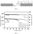
- FIG. 6 shows an example of lithium being precipitated onto surface of a current collector and lithium dendrites being generated in a charge and discharge process of Comparative Example 3. It can be learned from FIGs. 3 to 6 that the current collector according to this application can accurately limit the space for lithium precipitation, greatly suppressing the growth of lithium dendrites, thereby significantly improving cycling performance of batteries.
- FIG. 7 is a comparison diagram of performance of batteries in Example 1, Comparative Example 1, Comparative Example 2, and Comparative Example 3.
- the thickness of the lithiophilic layer has significant impact on battery performance.
- the lithiophilic layer is thin, it is difficult for the lithiophilic layer to provide enough space to accommodate precipitated lithium metal, and therefore limited improvement is made in battery cycling.
- the lithiophilic layer is too thick, lithium metal needs to go through a long diffusion process when lithium metal is precipitated/dissolved at the negative electrode side, resulting in increased transmission polarization, which is not conducive to stability of long-term cycling. Therefore, the thickness of the lithiophilic layer is 1-500 ⁇ m, and preferably 10-100 ⁇ m.
- the average thickness of the external structure of the lithiophilic material is 0.05-2 ⁇ m, and preferably 0.1-1 ⁇ m.
- the amount of the lithiophilic material has significant impact on battery performance.
- the amount of the lithiophilic material is too small, it is difficult to form enough lithiophilic sites, which is not conducive to the uniform precipitation and dissolution of lithium metal.
- the amount of the lithiophilic material is too large, the volume of the cavity is decreased, which is not conducive to accommodation of precipitated lithium metal, and the costs of the current collector are increased, which is not conducive to large-scale application. Therefore, the amount of the lithiophilic material is 1-10wt%.
- Example 26 and Comparative Example 5 It can be learned from analysis of the test results of Example 26 and Comparative Example 5 that the amount of electrolyte injected is based on the capacity, which is about 2.8 g/Ah. The amount of electrolyte injected generally falls within a range of 2.5-3 g/Ah. When the amount of electrolyte injected is lower than 2.5 g/Ah as in Example 26 and Comparative Example 5, high cycling performance (57 cycles) can still be seen in Example 26, while poor performance (only 28 cycles) is seen in Comparative Example 5. This further indicates that the lithiophilic material with a cavity structure in this application can reduce side reactions in cycling of lithium metal batteries.
Landscapes
- Chemical & Material Sciences (AREA)
- Chemical Kinetics & Catalysis (AREA)
- Electrochemistry (AREA)
- General Chemical & Material Sciences (AREA)
- Engineering & Computer Science (AREA)
- Materials Engineering (AREA)
- Manufacturing & Machinery (AREA)
- Composite Materials (AREA)
- Cell Electrode Carriers And Collectors (AREA)
Abstract
Description
- This application refers to
Chinese Patent Application No. 202110359020.8, filed on April 1, 2021 - This application pertains to the field of batteries, and relates to a current collector and a preparation method thereof. This application further relates to a secondary battery containing such current collector, and an apparatus containing such secondary battery.
- Lithium metal (Li) has advantages such as extremely high theoretical specific capacity (3860 mAh•g-1), minimum reduction potential (-3.04 V vs. standard hydrogen electrode), minimum atomic radius, and low density (0.534 g•cm-3). However, during precipitation of lithium metal, lithium dendrites grow inevitably, causing huge safety risks in use of lithium metal batteries.
- From the perspective of current collectors, it is an effective method to design lithiophilic metal current collectors with nanostructure or microstructure. First, metal current collectors with nanostructure or microstructure can provide more abundant sites for lithium precipitation, thereby suppressing the generation of lithium dendrites. Second, lithiophilic current collectors can reduce nucleation of lithium precipitation, helping to reduce the energy barrier of lithium precipitation. However, although applying lithiophilic current collectors on the surface of substrates can improve uniformity of lithium precipitation, this method has the following problems: first, metal current collectors with nanostructure or microstructure are too expensive to implement mass production in preparation; and second, even if the surface of existing current collectors is plated with a lithiophilic material layer, lithium metal is still precipitated on the surface of the lithiophilic material, and lithium dendrites are still inevitably generated when precipitation reaches a specific extent, severely affecting the cycling and safety performance of batteries.
- Therefore, the foregoing problems of metal current collectors need to be resolved urgently for lithium metal batteries.
- Considering the problems described in the Background, this application aims to provide a current collector, a preparation method of current collector, a secondary battery containing such current collector, and an apparatus containing such secondary battery. The current collector can effectively suppress lithium dendrites when used in secondary batteries.
- To achieve the foregoing objectives, a first aspect of this application provides a current collector, including:
- a current collector body; and
- a lithiophilic layer applied on surface of the current collector body, where the lithiophilic layer has lithium affinity and includes multiple lithiophilic materials, the lithiophilic materials include an internal structure and an external structure, and the internal structure is a cavity.
- A second aspect of this application provides a preparation method of current collector, including the following steps:
- (1) providing materials with a composite structure, where
the material with a composite structure has an internal structure and an external structure, a material of the internal structure is a metal A, and a material of the external structure is a metal B and/or B oxide with lithium affinity, where the metal A is metal copper or selected from metals whose oxidation potential is lower than the metal copper, and the metal B is selected from metals whose oxidation potential is higher than the metal A; - (2) letting multiple materials with a composite structure react with an acid solution to form multiple lithiophilic materials with lithium affinity, where the lithiophilic material includes an internal structure and an external structure, and the internal structure is a cavity; and
- (3) applying the multiple lithiophilic materials on surface of a current collector body.
- A third aspect of this application provides a secondary battery, including the current collector according to the first aspect of this application or the preparation method of current collector according to the second aspect of this application.
- A fourth aspect of this application provides an apparatus, including the secondary battery according to the third aspect of this application.
- This application has the following beneficial effects:
- The metal current collector based on lithium metal battery of this application solves problems such as many generated lithium dendrites for current collectors. Silver microparticles whose internal structure is a cavity are used as an example. This material is made by using currently commercialized silver-coated copper microparticles as the raw material, and corroding the intermediate copper layer with an acid solution to form a cavity structure. Due to lithium affinity of the silver shell layer, lithium metal can be precipitated into the cavity structure during charge and discharge. As compared with silver coating, this method is not only simple to operate, but also can accurately limit the space for lithium precipitation, greatly suppressing the growth of lithium dendrites, thereby significantly improving cycling performance of batteries. In addition, as compared with ordinary three-dimensional current collectors, the closed space structure in the silver shell can effectively reduce electrolyte consumed during lithium precipitation, which is beneficial to the long-term operation of batteries.
- To describe the technical solutions in embodiments of this application more clearly, the following briefly describes the accompanying drawings required for describing the embodiments of this application. Apparently, the accompanying drawings in the following description show merely some embodiments of this application, and a person of ordinary skill in the art may still derive other drawings from the accompanying drawings without creative efforts.
-
FIG. 1 is a schematic diagram of a preparation process of current collector according to Example 1 of this application. -
FIG. 2 is a schematic diagram of a preparation process of current collector according to Example 11 of this application. -
FIG. 3 shows an example of lithium being precipitated into a silver shell layer with cavity structure in a charge and discharge process of Example 1 of this application. -
FIG. 4 shows an example of lithium being precipitated into a silver shell layer with cavity structure in a charge and discharge process of Example 11 of this application. -
FIG. 5 shows an example of lithium being precipitated onto surface of silver-coated copper powder with no cavity structure in a charge and discharge process of Comparative Example 1. -
FIG. 6 shows an example of lithium being precipitated onto surface of a current collector and lithium dendrites being generated in a charge and discharge process of Comparative Example 3. -
FIG. 7 is a comparison diagram of performance of batteries in Example 1, Comparative Example 1, Comparative Example 2, and Comparative Example 3 of this application. - The following further describes this application with reference to specific embodiments. It should be understood that these specific embodiments are merely intended to illustrate this application but not to limit the scope of this application.
- For brevity, this specification specifically discloses only some numerical ranges. However, any lower limit may be combined with any upper limit to form a range not explicitly recorded, and any lower limit may be combined with another lower limit to form a range not explicitly recorded, and likewise, any upper limit may be combined with any other upper limit to form a range not explicitly recorded. In addition, each individually disclosed point or single numerical value, as a lower limit or an upper limit, may be combined with any other point or single numerical value or combined with another lower limit or upper limit to form an unspecified range.
- In the descriptions of this specification, it should be noted that "more than" and "less than" are inclusive of the present number and that "more" in "one or more" means two or more than two, unless otherwise specified.
- Unless otherwise specified, terms used in this application have common meanings generally understood by persons skilled in the art. Unless otherwise specified, numerical values of parameters mentioned in this application may be measured by using various measurement methods commonly used in the art (for example, testing may be performed by using a method provided in the embodiments of this application).
- The following details a current collector according to a first aspect of this application, a preparation method of current collector according to a second aspect of this application, a secondary battery according to a third aspect of this application, and an apparatus according to a fourth aspect of this application.
- The current collector according to the first aspect of this application is described first, including:
- a current collector body; and
- a lithiophilic layer applied on surface of the current collector body, where the lithiophilic layer has lithium affinity and includes multiple lithiophilic materials, the lithiophilic materials include an internal structure and an external structure, and the internal structure is a cavity.
- The inventors have found through research that in the current collector of this application, due to the lithium affinity of the shell layer, lithium metal can be precipitated into the cavity structure during charge and discharge, thereby greatly suppressing the growth of lithium dendrites, and significantly improving the cycling performance of batteries.
- According to some embodiments of the current collector of this application, morphology of the external structure of the lithiophilic material is selected from one or more of granular structure, linear structure, plate structure, spherical shape, and near-spherical shape.
FIG. 1 shows an example of an embodiment of a current collector according to this application, where an external structure of a lithiophilic material is a granular structure.FIG. 2 shows an example of a schematic diagram of an embodiment of a current collector according to this application, where an external structure of a lithiophilic material is a linear structure. Embodiments of the current collector according to this application are not limited thereto. The foregoing external structure may be a nano-scale structure or a micro-scale structure. Preferably, selecting the foregoing structure can increase a specific surface area of the lithiophilic material. This can increase sites for active reaction during lithium precipitation, and reduce current density, thereby facilitating uniform distribution of electrons, and improving uniformity of lithium precipitation. - According to some embodiments of the current collector of this application, an average thickness of the external structure of the lithiophilic material is 0.05-2 µm, and preferably 0.1-1 µm. In this application, the average thickness of the external structure refers to an average value of multiple thicknesses of the external structure, for example, 0.05 µm, 0.07 µm, 0.1 µm, 0.3 µm, 0.5 µm, 0.7 µm, 1 µm, 1.3 µm, 1.5 µm, 1.7 µm, 2 µm, and any value therebetween. Preferably, the average thickness of the external structure falling within the range defined in this application can help the lithiophilic material to maintain a stable cavity structure, and allow diffusion of lithium ions into the internal cavity through the external structure so that lithium ions are precipitated in the internal cavity structures.
- According to some embodiments of the current collector of this application, a material of the external structure of the lithiophilic material is metal and/or metal oxide with lithium affinity, and preferably selected from one or more of gold, silver, platinum, and silver oxide. In this application, a material of the external structure of the current collector may be a product of reaction between one or more of silver-coated tin powder, silver-coated zinc powder, silver-coated iron powder, silver-coated aluminum powder, silver-coated copper powder, gold-coated tin powder, gold-coated zinc powder, gold-coated iron powder, gold-coated aluminum powder, gold-coated copper powder, platinum-coated tin powder, platinum-coated zinc powder, platinum-coated iron powder, platinum-coated aluminum powder, and platinum-coated copper powder and an acid solution (sulfuric acid and/or hydrochloric acid). Preferably, the material of the external structure of the lithiophilic material has good oxidation resistance so as not to react with the acid solution during acid treatment, maintaining the stability of the external structure, thereby forming the lithiophilic material with the cavity structure.
- According to some embodiments of the current collector of this application, the thickness of the lithiophilic layer is 1-500 µm, and preferably 10-100 µm. In this application, the thickness of the lithiophilic layer is an overall thickness of the outer lithiophilic layer, for example, 1 µm, 10 µm, 50 µm, 100 µm, 200 µm, 300 µm, 400 µm, 500 µm, and any value therebetween. Preferably, with the thickness of the lithiophilic layer falling within the range defined in this application, all lithium ions transported from a positive electrode can be accommodated, and lithium ions are precipitated in the cavity structure of the lithiophilic material, thereby effectively suppressing battery volume change caused by lithium precipitation. An appropriate thickness of the lithiophilic layer can reduce adverse effects on mass energy density and volumetric energy density.
- According to some embodiments of the current collector of this application, the current collector body is metal foil, and preferably copper foil.
- In a second aspect, this application provides a preparation method of current collector, including the following steps:
- (1) providing materials with a composite structure, where
the material with a composite structure has an internal structure and an external structure, a material of the internal structure is a metal A, and a material of the external structure is a metal B and/or B oxide with lithium affinity, where the metal A is metal copper or selected from metals whose oxidation potential is lower than the metal copper, and the metal B is selected from metals whose oxidation potential is higher than the metal A; - (2) letting multiple materials with a composite structure react with an acid solution to form multiple lithiophilic materials with lithium affinity, where the lithiophilic material includes an internal structure and an external structure, and the internal structure is a cavity; and
- (3) applying the multiple lithiophilic materials on surface of a current collector body.
- The preparation method in this application is simple to operate, and can accurately limit the space for lithium precipitation, greatly suppressing the growth of lithium dendrites, thereby significantly improving cycling performance of batteries.
- According to some embodiments of the preparation method of this application, the metal A is selected from one or more of tin, zinc, iron, aluminum, and copper. In this application, the selected metal A has low oxidation resistance, and undergoes oxidation-reduction reaction with an acid solution during acid treatment to form an internal cavity structure.
- According to some embodiments of the preparation method of this application, the metal B is one or more of gold, silver, and platinum. In this application, the selected metal B has high oxidation resistance so as not to react with an acid solution during acid treatment, thereby maintaining the stability of the external structure.
- According to some embodiments of the preparation method of this application, preferably, the material with a composite structure is one or more of silver-coated tin powder, silver-coated zinc powder, silver-coated iron powder, silver-coated aluminum powder, silver-coated copper powder, gold-coated tin powder, gold-coated zinc powder, gold-coated iron powder, gold-coated aluminum powder, gold-coated copper powder, platinum-coated tin powder, platinum-coated zinc powder, platinum-coated iron powder, platinum-coated aluminum powder, and platinum-coated copper powder. In this application, the selected material with a composite structure can selectively dissolve an internal material with low oxidation resistance through acid treatment, while maintaining a stable external structure, thereby forming a lithiophilic material with an internal cavity structure.
- According to some embodiments of the preparation method of this application, based on a total weight of the materials with a composite structure, amount of the metal B is 1wt% to 10wt%. for example, 1wt%, 2wt%, 3wt%, 4wt%, 5wt%, 6wt%, 7wt%, 8wt%, 9wt%, 10wt%, and any value therebetween. In this application, the amount of the metal B needs to be high enough to maintain the stability of the lithiophilic material with a cavity structure, and also needs to be controlled not to be too high because a too high amount suppresses the formation of the internal cavity structure, and such suppressing does not help achieve the purpose of lithium precipitation in the cavity structure.
- According to some embodiments of the preparation method of this application, potential of the acid solution is between potentials of the internal structure and the external structure, and preferably selected from sulfuric acid and/or hydrochloric acid. In this application, a proper solution such as concentrated sulfuric acid is used to corrode the raw material. The potential of the solute in the solution is between potentials of the inner and outer layers of the raw material, so that the solution reacts only with the inner layer of the raw material but not the outer layer, forming a lithiophilic layer whose internal structure is a cavity.
- According to some embodiments of the preparation method of this application, the external structure of the material with a composite structure has nano-scale pores for lithium ions and/or hydrogen ions to pass through the external structure and enter the internal structure.
- According to some embodiments of the preparation method of this application, the applying method in step (3) includes mixing the multiple lithiophilic materials with a dispersion liquid, and applying the mixture on the surface of the current collector body to form the lithiophilic layer on the surface of the current collector body. In this application, the number of multiple lithiophilic materials is not particularly limited provided that the lithiophilic layer has the desired thickness.
- According to some embodiments of the preparation method of this application, the dispersion liquid includes but is not limited to water, ethanol, ethylene glycol, N-methylpyrrolidone, and N,N-dimethylformamide. The dispersion liquid may be a mixture of one or more of the foregoing substances.
- According to some embodiments of the preparation method of this application, a weight ratio of the current collector and the dispersion liquid has a wide selection range, provided that the resulting mixture can be evenly applied on the surface of the current collector body.
- According to some embodiments of the preparation method of this application, the coating method includes but is not limited to pulling method, film drawing method, electrostatic spraying method, spin coating method, and the like. The pulling method, film drawing method, electrostatic spraying method, and spin coating method may be conventional operations in the field, and details are not repeated herein.
- According to some embodiments of the preparation method of this application, the method further includes drying after step (3), and preferably conditions for the drying include: temperature being 70°C-90°C, and time being 1 h-4 h.
- According to a third aspect, this application provides a secondary battery, including the current collector according to the first aspect of this application or the preparation method of current collector according to the second aspect of this application. In a charge and discharge process of the battery, active ions are intercalated and deintercalated between a positive electrode plate and a negative electrode plate. The electrolyte conducts ions between the positive electrode plate and the negative electrode plate.
- According to some embodiments of the secondary battery of this application, the battery is an alkali metal battery, and preferably a lithium metal battery, a potassium metal battery, or a sodium metal battery.
- According to some embodiments of the secondary battery of this application, the secondary battery further includes a positive electrode, a negative electrode, an electrolyte, and a separator.
- According to some embodiments of the secondary battery of this application, the negative electrode includes but is not limited to lithium metal, potassium metal, or sodium metal.
- According to some embodiments of the secondary battery of this application, the positive electrode includes but is not limited to lithium iron phosphate, lithium cobaltate, lithium titanate, lithium nickel cobalt manganese oxide, and the like.
- According to some embodiments of the secondary battery of this application, the electrolyte conducts ions between the positive electrode plate and the negative electrode plate. The electrolyte is not specifically limited to any particular type in this application, and may be selected based on a need. For example, the electrolyte may be selected from at least one of a solid electrolyte and a liquid electrolyte (that is, an electrolyte solution).
- According to some embodiments of the secondary battery of this application, the electrolyte is an electrolyte solution. The electrolyte solution includes an electrolytic salt and a solvent.
- According to some embodiments of the secondary battery of this application, the electrolytic salt may be one or more of lithium hexafluorophosphate (LiPF6), lithium tetrafluoroborate (LiBF4), lithium perchlorate (LiClO4), lithium hexafluoroarsenate (LiAsF6), lithium bis(fluorosulfonyl)imide (LiFSI), lithium bistrifluoromethanesulfonimide (LiTFSI), lithium trifluoromethanesulfonate (LiTFS), lithium difluoro(oxalato)borate (LiDFOB), lithium dioxalate borate (LiBOB), lithium difluorophosphate (LiPO2F2), lithium difluoro(dioxalato)phosphate (LiDFOP), and lithium tetrafluoro oxalato phosphate (LiTFOP).
- According to some embodiments of the secondary battery of this application, the solvent may be selected from one or more of ethylene carbonate (EC), propylene carbonate (PC), ethyl methyl carbonate (EMC), diethyl carbonate (DEC), dimethyl carbonate (DMC), dipropyl carbonate (DPC), methyl propyl carbonate (MPC), ethyl propyl carbonate (EPC), butylene carbonate (BC), fluoroethylene carbonate (FEC), methyl formate (MF), methyl acetate (MA), ethyl acetate (EA), propyl acetate (PA), methyl propionate (MP), ethyl propionate (EP), propyl propionate (PP), methyl butyrate (MB), ethyl butyrate (EB), 1,4-butyrolactone (GBL), sulfolane (SF), methyl sulfonyl methane (MSM), methyl ethyl sulfone (EMS), and diethyl sulfone (ESE).
- According to some embodiments of the secondary battery of this application, the electrolyte further includes an additive. For example, the additive may include a negative electrode film-forming additive, or may include a positive electrode film-forming additive, or may include an additive capable of improving some performance of the battery, for example, an additive for improving overcharge performance of the battery, an additive for improving high-temperature performance of the battery, or an additive for improving low-temperature performance of the battery.
- According to some embodiments of the secondary battery of this application, secondary batteries using an electrolyte solution and some secondary batteries using a solid electrolyte further include a separator. The separator is disposed between the positive electrode plate and the negative electrode plate to provide separation. The separator is not limited to any specific type in this application, and may be any commonly known porous separator with high chemical stability and mechanical stability.
- According to some embodiments of the secondary battery of this application, a material of the separator may be selected from one or more of glass fiber, non-woven fabric, polyethylene, polypropylene, and polyvinylidene fluoride. The separator may be a single-layer thin film or a multilayer composite thin film. When the separator is a multilayer composite thin film, each layer may be made of the same or different materials.
- According to some embodiments of the secondary battery of this application, the positive electrode plate, the negative electrode plate, and the separator may be made into an electrode assembly through winding or lamination.
- According to some embodiments of the secondary battery of this application, the secondary battery may include an outer package. The outer package is used for packaging the electrode assembly and the electrolyte.
- According to some embodiments of the secondary battery of this application, the outer package of the secondary battery may be a hard shell, for example, a hard plastic shell, an aluminum shell, or a steel shell. The outer package of the secondary battery may alternatively be a soft package, for example, a soft pouch. A material of the soft pack may be plastic, for example, one or more of polypropylene (PP), polybutylene terephthalate (PBT), polybutylene succinate (PBS), and the like.
- The secondary battery is not limited to a particular shape in this application, and may be cylindrical, rectangular, or of any other shapes.
- According to some embodiments of the secondary battery of this application, the outer package may include a housing and a cover plate. The housing may include a base plate and side plates connected to the base plate, and the base plate and the side plates enclose an accommodating cavity. The housing has an opening communicating with the accommodating cavity, and the cover plate can cover the opening to close the accommodating cavity. A positive electrode plate, a negative electrode plate, and a separator may be made into an electrode assembly through winding or lamination. The electrode assembly is packaged in the accommodating cavity. The electrolyte solution infiltrates the electrode assembly. There may be one or more electrode assemblies in the secondary battery, and the quantity may be adjusted as required.
- According to a fourth aspect, this application provides an apparatus. The apparatus includes the secondary battery according to the third aspect of this application. The secondary battery may be used as a power source of the apparatus or an energy storage unit of the apparatus. The apparatus in this application uses the secondary battery provided in this application, and therefore has at least the same advantages as the secondary battery.
- The apparatus may be but is not limited to a mobile device (for example, a mobile phone or a laptop computer), an electric vehicle (for example, a battery electric vehicle, a hybrid electric vehicle, a plug-in hybrid electric vehicle, an electric bicycle, an electric scooter, an electric golf vehicle, or an electric truck), an electric train, a ship, a satellite, an energy storage system, and the like.
- For example, the apparatus may be a battery electric vehicle, a hybrid electric vehicle, a plug-in hybrid electric vehicle, a mobile phone, a tablet computer, a notebook computer, or the like.
- To explain technical contents, construction features, and objectives and effects achieved of the technical solutions in detail, detailed descriptions are given below with reference to specific examples. It should be understood that these examples are merely used to describe this application but not to limit the scope of this application.
- Polymers used in examples and comparative examples are as follows:
granular silver-coated copper powder, granular silver-coated tin powder, granular silver-coated zinc powder, granular silver-coated iron powder, granular silver-coated aluminum powder, rod-shaped (or linear) silver-coated copper powder, granular gold-coated copper powder, granular platinum-coated copper powder, and granular silver oxide-coated copper powder, all of which are commercially available. - In the following examples and comparative examples, the test method and instrument used for thickness of lithiophilic layer were: using a high-precision digimatic micrometer (MITUTOYO/293-100, Japan) for measuring the thicknesses of the current collector body and the current collector modified by the lithiophilic material respectively, and using a difference between the two as the thickness of the lithiophilic layer.
- The test method and the instrument used for the average thickness of the external structure of the lithiophilic material were: using a scanning electron microscope (JEOL/JSM-IT800SHL of Japan Electronics) for observing the cross section of lithiophilic material particles, and measuring and collecting statistics of thicknesses of different positions of the particle to calculate the average thickness of the external structure.
- Granular silver-coated copper powder (composite structure with an internal structure and an external structure, where a material of the internal structure was copper, and the external structure was made of silver, with a proportion of silver being 10wt%) was dispersed in a concentrated sulfuric acid solution, allowing them to react for 2 h so as to obtain multiple lithiophilic materials with lithium affinity. The lithiophilic material included an internal structure and an external structure, the internal structure was a cavity, and the external structure was a granular structure.
FIG. 1 is a schematic diagram of a preparation process of current collector. The multiple obtained lithiophilic materials were mixed with N-methylpyrrolidone (NMP) and polyvinylidene fluoride (PVDF) to make a conductive slurry. The slurry was applied on copper foil by using the wet film method, and then dried at 80°C for 2 h to obtain a current collector. The current collector included a current collector body and a lithiophilic layer applied on surface of the current collector body. The lithiophilic layer had a lithium affinity and included the multiple lithiophilic materials. The lithiophilic material included an internal structure and an external structure, the internal structure was a cavity, and morphology of the external structure was a microparticle structure. The thickness of the lithiophilic layer was 30 µm. The average thickness of the external structure of the lithiophilic material was 1 µm. - The current collector was directly matched with an NCM811 ternary positive electrode (with a loading amount of 3.5 mAh cm-2) to assemble a lithium metal pouch battery having no lithium negative electrode, with a capacity of 140 mAh and 0.4 g electrolyte injected.
- The method in Example 1 was used except that different parameters as shown in Table 1 were used so as to finally obtain respective batteries.
- As compared with Example 1, granular silver-coated copper powder (without a cavity structure) was directly mixed with NMP and PVDF to obtain a slurry. The slurry was applied on copper foil by using the wet film method, so as to obtain a current collector.
- The method in step (2) of Example 1 was used to prepare a battery. The battery was tested to check performance. Results are shown in Table 1.
- As compared with Example 1, silver was directly electroplated on the surface of copper foil to form a current collector of lithium metal battery, which was coated with a dense silver layer.
- The method in step (2) of Example 1 was used to prepare a battery. The battery was tested to check performance. Results are shown in Table 1.
- As compared with Example 1, copper foil was directly used as a current collector of lithium metal battery.
- The method in step (2) of Example 1 was used to prepare a battery. The battery was tested to check performance. Results are shown in Table 1.
- As compared with Example 1, brass foil was washed with hydrochloric acid to get rid of the zinc element in the brass so as to form a three-dimensional porous structure that serves as a current collector of lithium metal battery.
- The method in step (2) of Example 1 was used to prepare a battery. The battery was tested to check performance. Results are shown in Table 1.
- As compared with Comparative Example 4, 0.3 g electrolyte was injected, so as to obtain a current collector.
- The method in step (2) of Example 1 was used to prepare a battery. The battery was tested to check performance. Results are shown in Table 1.
- The method and conditions for testing performance of battery are as follows.
- The charge and discharge capacity performance of the battery was measured using a battery tester (Land, Wuhan, China), with a test temperature of 25°C, a test voltage range of 2.8-4.3 V, a test rate current of 0.3C (42 mA) for charge, and 0.3C for discharge. A discharge capacity after the first charge-discharge cycle of the battery was a first-cycle discharge capacity. A discharge capacity after a plurality of charge-discharge cycles was a cycling discharge capacity. The number of cycles when the cycling discharge capacity was reduced to 80% of the first-cycle discharge capacity was the number of cycles of the battery.
- The batteries of Examples 1 to 29 and Comparative Examples 1 to 5 were tested. Results are shown in Table 1.
Table 1 Parameters and performance test results of current collectors and batteries in Examples 1 to 29 and Comparative Examples 1 to 5 Outer coating material Inner material Solvent Preparation method Shape of outer particle Thickness of lithiophilic layer (µm) Thickness of outer layer (µm) Amount of lithiophilic material (%)∗ Amount of electrolyte injected (g) Number of cycles (capacity decay to 80%) Example 1 Silver Copper NMP Wet-film Granular 30 1 10 0.4 75 Example 2 Silver Tin NMP Wet-film Granular 30 1 10 0.4 73 Example 3 Silver Zinc NMP Wet-film Granular 30 1 10 0.4 72 Example 4 Silver Iron NMP Wet-film Granular 30 1 10 0.4 74 Example 5 Silver Aluminum NMP Wet-film Granular 30 1 10 0.4 72 Example 6 Silver Copper DMF Wet-film Granular 30 1 10 0.4 69 Example 7 Silver Copper Ethanol Wet-film Granular 30 1 10 0.4 71 Example 8 Silver Copper NMP Pulling Granular 30 1 10 0.4 73 Example 9 Silver Copper NMP Spin coating Granular 30 1 10 0.4 72 Example 10 Silver Copper NMP Electrostatic spraying Granular 30 1 10 0.4 73 Example 11 Silver Copper NMP Wet-film Rod-shaped (linear) 30 1 10 0.4 74 Example 12 Silver Copper NMP Wet-film Granular 0.5 0.01 10 0.4 41 Example 13 Silver Copper NMP Wet-film Granular 1 0.05 10 0.4 55 Example 14 Silver Copper NMP Wet-film Granular 10 0.1 10 0.4 70 Example 15 Silver Copper NMP Wet-film Granular 100 1 10 0.4 65 Example 16 Silver Copper NMP Wet-film Granular 500 1 10 0.4 53 Example 17 Silver Copper NMP Wet-film Granular 1000 1 10 0.4 45 Example 18 Silver Copper NMP Wet-film Granular 30 0.01 10 0.4 40 Example 19 Silver Copper NMP Wet-film Granular 30 0.05 10 0.4 58 Example 20 Silver Copper NMP Wet-film Granular 30 0.1 10 0.4 70 Example 21 Silver Copper NMP Wet-film Granular 30 2 10 0.4 60 Example 22 Silver Copper NMP Wet-film Granular 30 4 10 0.4 46 Example 23 Silver Copper NMP Wet-film Granular 30 1 0.1 0.4 44 Example 24 Silver Copper NMP Wet-film Granular 30 1 1 0.4 69 Example 25 Silver Copper NMP Wet-film Granular 30 1 20 0.4 54 Example 26 Silver Copper NMP Wet-film Granular 30 1 10 0.3 57 Example 27 Gold Copper NMP Wet-film Granular 30 1 10 0.4 67 Example 28 Platinum Copper NMP Wet-film Granular 30 1 10 0.4 60 Example 29 Silver oxide Copper NMP Wet-film Granular 30 1 10 0.4 70 Comparative Example 1 Silver Copper NMP Wet-film Granular 30 1 10 0.4 36 Comparative Example 2 -- -- -- -- -- 0.4 37 Comparative Example 3 -- -- -- -- -- 0.4 10 Comparative Example 4 -- -- -- -- -- -- 0.4 35 Comparative Example 5 -- -- -- -- -- -- -- -- 0.3 28 * Amount of lithiophilic material (%) is an amount of the metal B or B oxide in the composite structure. -
FIG. 1 is a schematic diagram of a preparation process of current collector according to Example 1 of this application.FIG. 2 is a schematic diagram of a preparation process of current collector according to Example 11 of this application.FIG. 3 shows an example of lithium being precipitated into a silver shell layer with cavity structure in a charge and discharge process of Example 1 of this application.FIG. 4 shows an example of lithium being precipitated into a silver shell layer with cavity structure in a charge and discharge process of Example 11 of this application.FIG. 5 shows an example of lithium being precipitated onto surface of silver-coated copper powder with no cavity structure in a charge and discharge process of Comparative Example 1.FIG. 6 shows an example of lithium being precipitated onto surface of a current collector and lithium dendrites being generated in a charge and discharge process of Comparative Example 3. It can be learned fromFIGs. 3 to 6 that the current collector according to this application can accurately limit the space for lithium precipitation, greatly suppressing the growth of lithium dendrites, thereby significantly improving cycling performance of batteries. -
FIG. 7 is a comparison diagram of performance of batteries in Example 1, Comparative Example 1, Comparative Example 2, and Comparative Example 3. - It can be learned from Table 1 and
FIG. 7 that the number of cycles of the battery prepared by using the current collector of this application can be significantly increased. - It can be learned from analysis of the test results of Example 1 and Comparative Examples 1 to 4 that under the same conditions, if the current collector made of the lithiophilic material with a cavity structure of this application is used, lithium metal can be precipitated in the cavity structure during charge and discharge because of the lithium affinity of the silver shell layer. This method can accurately limit the space for lithium precipitation, greatly suppress the growth of lithium dendrites, and reduce side reactions between lithium dendrites and the electrolyte. Therefore, the number of cycles is significantly increased.
- It can be learned from the test results of Examples 2 to 5 that the different inner layer materials used do not affect the mechanism of the lithiophilic layer in improving lithium precipitation, and the effects of improving battery cycling performance are basically the same.
- It can be learned from the test results of Examples 6 to 10 that when different solvents or different current collector preparation processes are used, the use of lithiophilic materials with a cavity structure can still effectively improve the overall cycling performance of batteries.
- It can be learned from the test results of Example 11 that the use of a lithiophilic material with a different morphology does not affect the improvement of battery performance by current collectors.
- It can be learned from the test results of Examples 12 to 17 that the thickness of the lithiophilic layer has significant impact on battery performance. When the lithiophilic layer is thin, it is difficult for the lithiophilic layer to provide enough space to accommodate precipitated lithium metal, and therefore limited improvement is made in battery cycling. When the lithiophilic layer is too thick, lithium metal needs to go through a long diffusion process when lithium metal is precipitated/dissolved at the negative electrode side, resulting in increased transmission polarization, which is not conducive to stability of long-term cycling. Therefore, the thickness of the lithiophilic layer is 1-500 µm, and preferably 10-100 µm.
- It can be learned from the test results of Examples 18 to 22 that different average thicknesses of the outer layer structure of the lithiophilic material cause different lithium affinities and battery performance. Because when the outer layer structure is too thin, the overall stability of the cavity structure is so poor that it is difficult to maintain morphology of the cavity for a long time in cycling, resulting in damage of the lithiophilic layer structure. When the outer layer structure is too thick, diffusion and precipitation of lithium ions are hindered, and it is even difficult for lithium metal to be precipitated into the cavity, affecting application effects of the cavity structure. Therefore, the average thickness of the external structure of the lithiophilic material is 0.05-2 µm, and preferably 0.1-1 µm.
- It can be learned from the test results of Examples 23 to 25 that the amount of the lithiophilic material has significant impact on battery performance. When the amount of the lithiophilic material is too small, it is difficult to form enough lithiophilic sites, which is not conducive to the uniform precipitation and dissolution of lithium metal. When the amount of the lithiophilic material is too large, the volume of the cavity is decreased, which is not conducive to accommodation of precipitated lithium metal, and the costs of the current collector are increased, which is not conducive to large-scale application. Therefore, the amount of the lithiophilic material is 1-10wt%.
- It can be learned from analysis of the test results of Example 26 and Comparative Example 5 that the amount of electrolyte injected is based on the capacity, which is about 2.8 g/Ah. The amount of electrolyte injected generally falls within a range of 2.5-3 g/Ah. When the amount of electrolyte injected is lower than 2.5 g/Ah as in Example 26 and Comparative Example 5, high cycling performance (57 cycles) can still be seen in Example 26, while poor performance (only 28 cycles) is seen in Comparative Example 5. This further indicates that the lithiophilic material with a cavity structure in this application can reduce side reactions in cycling of lithium metal batteries.
- It can be learned from the test results of Example 1 and Examples 27 to 29 that all different lithiophilic materials can effectively improve lithium precipitation, and thus improve cycling performance of batteries.
- It should be noted that the foregoing embodiments are merely used to explain this application, and do not constitute any limitation to this application. This application has been described with reference to typical embodiments, but it should be understood that the terms used in these embodiments are descriptive and explanatory rather than limitative. Modification may be made as prescribed to this application within the scope of the claims of this application, and amendments may be made to this application without departing from the scope and spirit of this application. Although this application described therein relates to specific methods, materials, and embodiments, it does not mean that this application is limited to specific examples disclosed in the specific methods, materials, and embodiments. On the contrary, this application can be extended to all other methods and applications having the same function.
Claims (12)
- A current collector, comprising:a current collector body; anda lithiophilic layer applied on surface of the current collector body, wherein the lithiophilic layer has lithium affinity and comprises multiple lithiophilic materials, the lithiophilic materials comprise an internal structure and an external structure, and the internal structure is a cavity.
- The current collector according to claim 1, wherein morphology of the external structure of the lithiophilic material is selected from one or more of granular structure, linear structure, plate structure, spherical shape, and near-spherical shape.
- The current collector according to claim 1 or 2, wherein an average thickness of the external structure of the lithiophilic material is 0.05-2 µm, and preferably 0.1-1 µm.
- The current collector according to any one of claims 1 to 3, wherein a material of the external structure of the lithiophilic material is metal and/or metal oxide with lithium affinity, and preferably selected from one or more of gold, silver, platinum, and silver oxide.
- The current collector according to any one of claims 1 to 4, wherein thickness of the lithiophilic layer is 1-500 µm, and preferably 10-100 µm.
- The current collector according to any one of claims 1 to 5, wherein the current collector body is metal foil, and preferably copper foil.
- A preparation method of current collector, comprising the following steps:(1) providing materials with a composite structure, wherein
the material with a composite structure has an internal structure and an external structure, a material of the internal structure is a metal A, and a material of the external structure is a metal B and/or B oxide with lithium affinity, wherein the metal A is metal copper or selected from metals whose oxidation potential is lower than the metal copper, and the metal B is selected from metals whose oxidation potential is higher than the metal A;(2) letting multiple materials with a composite structure react with an acid solution to form multiple lithiophilic materials with lithium affinity, wherein the lithiophilic material comprises an internal structure and an external structure, and the internal structure is a cavity; and(3) applying the multiple lithiophilic materials on surface of a current collector body. - The preparation method according to claim 7, wherein the metal A is selected from one or more of tin, zinc, iron, aluminum, and copper, and the metal B is one or more of gold, silver, and platinum; and
preferably, the material with a composite structure is one or more of silver-coated tin powder, silver-coated zinc powder, silver-coated iron powder, silver-coated aluminum powder, silver-coated copper powder, gold-coated tin powder, gold-coated zinc powder, gold-coated iron powder, gold-coated aluminum powder, gold-coated copper powder, platinum-coated tin powder, platinum-coated zinc powder, platinum-coated iron powder, platinum-coated aluminum powder, and platinum-coated copper powder. - The preparation method according to claim 7 or 8, wherein based on a total weight of the materials with a composite structure, amount of the metal B is 1wt% to 10wt%.
- The preparation method according to any one of claims 7 to 9, wherein potential of the acid solution is between potentials of the internal structure and the external structure, and preferably selected from sulfuric acid and/or hydrochloric acid.
- A secondary battery, comprising the current collector according to any one of claims 1 to 6 or the current collector prepared in the preparation method according to any one of claims 7 to 10.
- An apparatus, comprising the secondary battery according to claim 11.
Applications Claiming Priority (2)
| Application Number | Priority Date | Filing Date | Title |
|---|---|---|---|
| CN202110359020.8A CN115172757B (en) | 2021-04-01 | 2021-04-01 | Current collector, preparation method thereof, secondary battery and device |
| PCT/CN2022/082661 WO2022206528A1 (en) | 2021-04-01 | 2022-03-24 | Current collector and preparation method therefor, and secondary battery and apparatus |
Publications (2)
| Publication Number | Publication Date |
|---|---|
| EP4220779A1 true EP4220779A1 (en) | 2023-08-02 |
| EP4220779A4 EP4220779A4 (en) | 2025-05-21 |
Family
ID=83457972
Family Applications (1)
| Application Number | Title | Priority Date | Filing Date |
|---|---|---|---|
| EP22778711.6A Pending EP4220779A4 (en) | 2021-04-01 | 2022-03-24 | Current collector and preparation method therefor, and secondary battery and apparatus |
Country Status (4)
| Country | Link |
|---|---|
| US (1) | US20230275236A1 (en) |
| EP (1) | EP4220779A4 (en) |
| CN (1) | CN115172757B (en) |
| WO (1) | WO2022206528A1 (en) |
Families Citing this family (4)
| Publication number | Priority date | Publication date | Assignee | Title |
|---|---|---|---|---|
| EP4564468A4 (en) * | 2023-01-03 | 2025-11-19 | Contemporary Amperex Technology Hong Kong Ltd | Negative electrode film, manufacturing process therefor, battery and electrical device |
| CN117219783B (en) * | 2023-10-18 | 2024-12-03 | 湘潭大学 | Composite current collector with lithium-philic structure, preparation method and battery |
| CN118016900B (en) * | 2024-04-09 | 2024-06-21 | 江苏康辉新材料科技有限公司 | Composite aluminum foil current collector and preparation method thereof |
| CN118919737B (en) * | 2024-10-11 | 2025-02-14 | 浙江金羽新能源科技有限公司 | Three-dimensional current collector and preparation method thereof and lithium battery |
Family Cites Families (21)
| Publication number | Priority date | Publication date | Assignee | Title |
|---|---|---|---|---|
| JP2007207679A (en) * | 2006-02-03 | 2007-08-16 | Canon Inc | Hollow platinum catalyst particles for fuel cells, membrane electrode assemblies, production methods thereof, and fuel cells |
| JP5488590B2 (en) * | 2009-04-09 | 2014-05-14 | 日産自動車株式会社 | Secondary battery current collector and secondary battery using the same |
| CN102554262B (en) * | 2012-02-23 | 2013-10-09 | 山东大学 | A hollow porous spherical platinum-silver alloy nanomaterial and preparation method thereof |
| US10170749B2 (en) * | 2016-06-07 | 2019-01-01 | Nanotek Instruments, Inc. | Alkali metal battery having an integral 3D graphene-carbon-metal hybrid foam-based electrode |
| KR102093969B1 (en) * | 2017-08-31 | 2020-03-26 | 주식회사 엘지화학 | Method for Preparing Hollow Type Structure |
| CN107910496B (en) * | 2017-10-09 | 2020-08-14 | 中南大学 | Metal lithium negative electrode for secondary battery, preparation method and application thereof |
| JP2019164907A (en) * | 2018-03-19 | 2019-09-26 | Tdk株式会社 | Lithium metal secondary battery |
| CN108735994A (en) * | 2018-05-24 | 2018-11-02 | 福州大学 | A kind of preparation method of N doping hollow carbon sphere |
| CN109103456B (en) * | 2018-06-29 | 2021-10-15 | 浙江工业大学 | A kind of preparation method of composite porous current collector for lithium metal anode protection |
| CN110828829B (en) * | 2018-08-14 | 2022-01-11 | 中南大学 | 3D lithium-philic porous metal current collector, negative electrode, preparation and application thereof |
| US10886528B2 (en) * | 2018-08-24 | 2021-01-05 | Global Graphene Group, Inc. | Protected particles of cathode active materials for lithium batteries |
| US11329282B2 (en) * | 2019-02-26 | 2022-05-10 | Bettergy Corp. | Rechargeable batteries and methods of making same |
| CN110212199A (en) * | 2019-05-30 | 2019-09-06 | 江汉大学 | A kind of conducting matrix grain and preparation method thereof |
| CN110148754B (en) * | 2019-05-31 | 2021-01-15 | 厦门大学 | Nitrogen-doped porous hollow carbon sphere, preparation method and application thereof, and lithium metal battery |
| CN112447949B (en) * | 2019-08-31 | 2021-08-27 | 中南大学 | Noble metal simple substance @ nitrogen-doped carbon hollow sphere material, lithium metal negative electrode active material, lithium metal negative electrode and preparation and application thereof |
| CN112670516B (en) * | 2019-11-15 | 2023-11-14 | 华中科技大学 | Three-dimensional composite current collector and preparation method thereof |
| CN111082066B (en) * | 2019-12-25 | 2020-12-22 | 山东大学 | A kind of three-dimensional lithiophilic conductive network material, preparation method and application |
| CN111088513B (en) * | 2020-01-17 | 2022-05-27 | 福建师范大学 | Silver nanoparticle modified TiO2Preparation method and application of nanotube array |
| CN111725513A (en) * | 2020-06-29 | 2020-09-29 | 珠海冠宇电池股份有限公司 | Composite shape memory alloy negative electrode and preparation method thereof and lithium battery |
| CN115298851B (en) * | 2020-07-06 | 2025-08-29 | 株式会社Lg新能源 | All-solid-state battery and manufacturing method thereof |
| CN213212183U (en) * | 2020-10-21 | 2021-05-14 | 山东省科学院新材料研究所 | Lithophilic nitrogen-doped carbon nanotubes three-dimensional composite lithium metal anode sheet |
-
2021
- 2021-04-01 CN CN202110359020.8A patent/CN115172757B/en active Active
-
2022
- 2022-03-24 WO PCT/CN2022/082661 patent/WO2022206528A1/en not_active Ceased
- 2022-03-24 EP EP22778711.6A patent/EP4220779A4/en active Pending
-
2023
- 2023-05-03 US US18/311,363 patent/US20230275236A1/en active Pending
Also Published As
| Publication number | Publication date |
|---|---|
| CN115172757B (en) | 2024-01-26 |
| EP4220779A4 (en) | 2025-05-21 |
| WO2022206528A1 (en) | 2022-10-06 |
| CN115172757A (en) | 2022-10-11 |
| US20230275236A1 (en) | 2023-08-31 |
Similar Documents
| Publication | Publication Date | Title |
|---|---|---|
| KR102718724B1 (en) | Positive electrode active material, method for producing same, positive electrode sheet, lithium ion secondary battery and battery module, battery pack and device related thereto | |
| EP3933981B1 (en) | Positive electrode active material and preparation method therefor, positive electrode plate, lithium ion secondary battery, and battery module, battery pack, and apparatus containing such lithium-ion secondary battery | |
| US11417883B2 (en) | Positive electrode active material, preparation method thereof, positive electrode plate, lithium-ion secondary battery as well as battery module, battery pack and apparatus containing lithium-ion secondary battery | |
| EP3944379B1 (en) | Positive electrode active material, preparation method therefor, positive electrode plate, lithium ion secondary battery, and battery module, battery pack and device comprising lithium ion secondary battery | |
| US12338137B2 (en) | Positive electrode active material and preparation method thereof, positive electrode plate, lithium-ion secondary battery, and battery module, battery pack, and apparatus containing such lithium-ion secondary battery | |
| EP3800707B1 (en) | Secondary battery, and related battery module, battery pack and apparatus | |
| EP4220779A1 (en) | Current collector and preparation method therefor, and secondary battery and apparatus | |
| US12230810B2 (en) | Secondary battery and apparatus containing the same | |
| EP4421889A1 (en) | Positive electrode plate, secondary battery, battery module, battery pack, and power consuming device | |
| US20220181675A1 (en) | Positive electrode active material and preparation method thereof, positive electrode plate, lithium-ion secondary battery, and apparatus containing such lithium-ion secondary battery | |
| EP3951988B1 (en) | Electrolyte and lithium metal battery comprising said electrolyte, battery module, battery pack, and apparatus | |
| JP7454059B2 (en) | Lithium ion batteries, battery modules, battery packs and power consumption devices | |
| EP4138158B1 (en) | Composite positive electrode material and preparation method thereof, secondary battery, battery group including secondary battery, and electric apparatus including secondary battery. | |
| CN118525386A (en) | Composite positive electrode material, preparation method thereof, secondary battery, battery module, battery pack and power-consuming device | |
| EP4102595A1 (en) | Negative electrode sheet, preparation method therefor, and secondary battery, battery module, battery pack, and electric apparatus containing same | |
| US20230278886A1 (en) | Ternary precursor material, and preparation method and application thereof | |
| EP4672414A1 (en) | ELECTROLYTE, SODIUM SECONDARY BATTERY AND ELECTRICAL DEVICE | |
| CN119725483B (en) | A lithium-ion battery anode material of niobium tungstate-coated silicon nanoparticles, its preparation method, anode sheet, and lithium-ion battery. | |
| CN119452480B (en) | Positive electrode plate, preparation method thereof, battery cell, battery and power utilization device | |
| EP4496033A1 (en) | Positive electrode active material, preparation method, secondary battery and electrical device |
Legal Events
| Date | Code | Title | Description |
|---|---|---|---|
| STAA | Information on the status of an ep patent application or granted ep patent |
Free format text: STATUS: THE INTERNATIONAL PUBLICATION HAS BEEN MADE |
|
| PUAI | Public reference made under article 153(3) epc to a published international application that has entered the european phase |
Free format text: ORIGINAL CODE: 0009012 |
|
| STAA | Information on the status of an ep patent application or granted ep patent |
Free format text: STATUS: REQUEST FOR EXAMINATION WAS MADE |
|
| 17P | Request for examination filed |
Effective date: 20230427 |
|
| AK | Designated contracting states |
Kind code of ref document: A1 Designated state(s): AL AT BE BG CH CY CZ DE DK EE ES FI FR GB GR HR HU IE IS IT LI LT LU LV MC MK MT NL NO PL PT RO RS SE SI SK SM TR |
|
| DAV | Request for validation of the european patent (deleted) | ||
| DAX | Request for extension of the european patent (deleted) | ||
| RAP1 | Party data changed (applicant data changed or rights of an application transferred) |
Owner name: CONTEMPORARY AMPEREX TECHNOLOGY(HONG KONG) LIMITED |
|
| A4 | Supplementary search report drawn up and despatched |
Effective date: 20250423 |
|
| RIC1 | Information provided on ipc code assigned before grant |
Ipc: H01M 10/052 20100101ALN20250415BHEP Ipc: H01M 4/70 20060101ALI20250415BHEP Ipc: H01M 4/04 20060101ALI20250415BHEP Ipc: H01M 4/66 20060101AFI20250415BHEP |