EP4220747A1 - Electrode and method for manufacturing electrode - Google Patents
Electrode and method for manufacturing electrode Download PDFInfo
- Publication number
- EP4220747A1 EP4220747A1 EP22788382.4A EP22788382A EP4220747A1 EP 4220747 A1 EP4220747 A1 EP 4220747A1 EP 22788382 A EP22788382 A EP 22788382A EP 4220747 A1 EP4220747 A1 EP 4220747A1
- Authority
- EP
- European Patent Office
- Prior art keywords
- electrode
- unit
- collector
- base
- active material
- Prior art date
- Legal status (The legal status is an assumption and is not a legal conclusion. Google has not performed a legal analysis and makes no representation as to the accuracy of the status listed.)
- Granted
Links
Images



Classifications
-
- H—ELECTRICITY
- H01—ELECTRIC ELEMENTS
- H01M—PROCESSES OR MEANS, e.g. BATTERIES, FOR THE DIRECT CONVERSION OF CHEMICAL ENERGY INTO ELECTRICAL ENERGY
- H01M4/00—Electrodes
- H01M4/02—Electrodes composed of, or comprising, active material
- H01M4/64—Carriers or collectors
- H01M4/66—Selection of materials
-
- H—ELECTRICITY
- H01—ELECTRIC ELEMENTS
- H01M—PROCESSES OR MEANS, e.g. BATTERIES, FOR THE DIRECT CONVERSION OF CHEMICAL ENERGY INTO ELECTRICAL ENERGY
- H01M4/00—Electrodes
- H01M4/02—Electrodes composed of, or comprising, active material
- H01M4/64—Carriers or collectors
- H01M4/70—Carriers or collectors characterised by shape or form
-
- H—ELECTRICITY
- H01—ELECTRIC ELEMENTS
- H01M—PROCESSES OR MEANS, e.g. BATTERIES, FOR THE DIRECT CONVERSION OF CHEMICAL ENERGY INTO ELECTRICAL ENERGY
- H01M10/00—Secondary cells; Manufacture thereof
- H01M10/04—Construction or manufacture in general
-
- H—ELECTRICITY
- H01—ELECTRIC ELEMENTS
- H01M—PROCESSES OR MEANS, e.g. BATTERIES, FOR THE DIRECT CONVERSION OF CHEMICAL ENERGY INTO ELECTRICAL ENERGY
- H01M10/00—Secondary cells; Manufacture thereof
- H01M10/04—Construction or manufacture in general
- H01M10/0413—Large-sized flat cells or batteries for motive or stationary systems with plate-like electrodes
-
- H—ELECTRICITY
- H01—ELECTRIC ELEMENTS
- H01M—PROCESSES OR MEANS, e.g. BATTERIES, FOR THE DIRECT CONVERSION OF CHEMICAL ENERGY INTO ELECTRICAL ENERGY
- H01M10/00—Secondary cells; Manufacture thereof
- H01M10/05—Accumulators with non-aqueous electrolyte
- H01M10/052—Li-accumulators
-
- H—ELECTRICITY
- H01—ELECTRIC ELEMENTS
- H01M—PROCESSES OR MEANS, e.g. BATTERIES, FOR THE DIRECT CONVERSION OF CHEMICAL ENERGY INTO ELECTRICAL ENERGY
- H01M10/00—Secondary cells; Manufacture thereof
- H01M10/05—Accumulators with non-aqueous electrolyte
- H01M10/058—Construction or manufacture
- H01M10/0585—Construction or manufacture of accumulators having only flat construction elements, i.e. flat positive electrodes, flat negative electrodes and flat separators
-
- H—ELECTRICITY
- H01—ELECTRIC ELEMENTS
- H01M—PROCESSES OR MEANS, e.g. BATTERIES, FOR THE DIRECT CONVERSION OF CHEMICAL ENERGY INTO ELECTRICAL ENERGY
- H01M4/00—Electrodes
- H01M4/02—Electrodes composed of, or comprising, active material
-
- H—ELECTRICITY
- H01—ELECTRIC ELEMENTS
- H01M—PROCESSES OR MEANS, e.g. BATTERIES, FOR THE DIRECT CONVERSION OF CHEMICAL ENERGY INTO ELECTRICAL ENERGY
- H01M4/00—Electrodes
- H01M4/02—Electrodes composed of, or comprising, active material
- H01M4/04—Processes of manufacture in general
-
- H—ELECTRICITY
- H01—ELECTRIC ELEMENTS
- H01M—PROCESSES OR MEANS, e.g. BATTERIES, FOR THE DIRECT CONVERSION OF CHEMICAL ENERGY INTO ELECTRICAL ENERGY
- H01M4/00—Electrodes
- H01M4/02—Electrodes composed of, or comprising, active material
- H01M4/04—Processes of manufacture in general
- H01M4/0402—Methods of deposition of the material
- H01M4/0404—Methods of deposition of the material by coating on electrode collectors
-
- H—ELECTRICITY
- H01—ELECTRIC ELEMENTS
- H01M—PROCESSES OR MEANS, e.g. BATTERIES, FOR THE DIRECT CONVERSION OF CHEMICAL ENERGY INTO ELECTRICAL ENERGY
- H01M4/00—Electrodes
- H01M4/02—Electrodes composed of, or comprising, active material
- H01M4/13—Electrodes for accumulators with non-aqueous electrolyte, e.g. for lithium-accumulators; Processes of manufacture thereof
-
- H—ELECTRICITY
- H01—ELECTRIC ELEMENTS
- H01M—PROCESSES OR MEANS, e.g. BATTERIES, FOR THE DIRECT CONVERSION OF CHEMICAL ENERGY INTO ELECTRICAL ENERGY
- H01M4/00—Electrodes
- H01M4/02—Electrodes composed of, or comprising, active material
- H01M4/13—Electrodes for accumulators with non-aqueous electrolyte, e.g. for lithium-accumulators; Processes of manufacture thereof
- H01M4/139—Processes of manufacture
-
- H—ELECTRICITY
- H01—ELECTRIC ELEMENTS
- H01M—PROCESSES OR MEANS, e.g. BATTERIES, FOR THE DIRECT CONVERSION OF CHEMICAL ENERGY INTO ELECTRICAL ENERGY
- H01M4/00—Electrodes
- H01M4/02—Electrodes composed of, or comprising, active material
- H01M4/64—Carriers or collectors
-
- H—ELECTRICITY
- H01—ELECTRIC ELEMENTS
- H01M—PROCESSES OR MEANS, e.g. BATTERIES, FOR THE DIRECT CONVERSION OF CHEMICAL ENERGY INTO ELECTRICAL ENERGY
- H01M4/00—Electrodes
- H01M4/02—Electrodes composed of, or comprising, active material
- H01M4/64—Carriers or collectors
- H01M4/66—Selection of materials
- H01M4/661—Metal or alloys, e.g. alloy coatings
-
- H—ELECTRICITY
- H01—ELECTRIC ELEMENTS
- H01M—PROCESSES OR MEANS, e.g. BATTERIES, FOR THE DIRECT CONVERSION OF CHEMICAL ENERGY INTO ELECTRICAL ENERGY
- H01M50/00—Constructional details or processes of manufacture of the non-active parts of electrochemical cells other than fuel cells, e.g. hybrid cells
- H01M50/40—Separators; Membranes; Diaphragms; Spacing elements inside cells
- H01M50/46—Separators, membranes or diaphragms characterised by their combination with electrodes
-
- H—ELECTRICITY
- H01—ELECTRIC ELEMENTS
- H01M—PROCESSES OR MEANS, e.g. BATTERIES, FOR THE DIRECT CONVERSION OF CHEMICAL ENERGY INTO ELECTRICAL ENERGY
- H01M2220/00—Batteries for particular applications
- H01M2220/20—Batteries in motive systems, e.g. vehicle, ship, plane
-
- Y—GENERAL TAGGING OF NEW TECHNOLOGICAL DEVELOPMENTS; GENERAL TAGGING OF CROSS-SECTIONAL TECHNOLOGIES SPANNING OVER SEVERAL SECTIONS OF THE IPC; TECHNICAL SUBJECTS COVERED BY FORMER USPC CROSS-REFERENCE ART COLLECTIONS [XRACs] AND DIGESTS
- Y02—TECHNOLOGIES OR APPLICATIONS FOR MITIGATION OR ADAPTATION AGAINST CLIMATE CHANGE
- Y02E—REDUCTION OF GREENHOUSE GAS [GHG] EMISSIONS, RELATED TO ENERGY GENERATION, TRANSMISSION OR DISTRIBUTION
- Y02E60/00—Enabling technologies; Technologies with a potential or indirect contribution to GHG emissions mitigation
- Y02E60/10—Energy storage using batteries
-
- Y—GENERAL TAGGING OF NEW TECHNOLOGICAL DEVELOPMENTS; GENERAL TAGGING OF CROSS-SECTIONAL TECHNOLOGIES SPANNING OVER SEVERAL SECTIONS OF THE IPC; TECHNICAL SUBJECTS COVERED BY FORMER USPC CROSS-REFERENCE ART COLLECTIONS [XRACs] AND DIGESTS
- Y02—TECHNOLOGIES OR APPLICATIONS FOR MITIGATION OR ADAPTATION AGAINST CLIMATE CHANGE
- Y02P—CLIMATE CHANGE MITIGATION TECHNOLOGIES IN THE PRODUCTION OR PROCESSING OF GOODS
- Y02P70/00—Climate change mitigation technologies in the production process for final industrial or consumer products
- Y02P70/50—Manufacturing or production processes characterised by the final manufactured product
Definitions
- the present invention relates to an electrode and a method for manufacturing the electrode, and more particularly, to an electrode capable of preventing a bending phenomenon of an electrode active material coating or a delamination or cracking phenomenon of an electrode active material from occurring and a method for manufacturing the electrode.
- Secondary batteries are rechargeable unlike primarily batteries, and also, the possibility of compact size and high capacity is high. Thus, recently, many studies on secondary batteries are being carried out. Such a secondary battery is manufactured in a shape in which one battery cell is packaged in a pack form or a pack shape in which several tens of battery cells are connected to each other. As a result, secondary batteries are being widely used for power sources for driving motors of vehicles.
- an electrode 10 of a secondary battery is manufactured by applying (coating) an electrode active material 12 on a metal base material (metal collector) 11 (see FIG. 1 ).
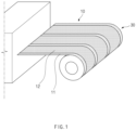
- FIG. 1 is a perspective view illustrating a state in which an electrode is manufactured and then wound on a roll according to a related art.
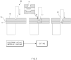
- FIG. 2 is a cross-sectional view illustrating a state in which the electrode is unwound from the roll manufactured in FIG. 1 and cut using a cutter so as to use the electrode by implementing the electrode in a specific shape.
- the electrode 10 coated with an electrode active material 12 is wound on a (electrode) roll 30 as illustrated in FIG. 1 because the electrode 10 has to be transferred or stored until used.
- the electrode is unwound from the (electrode) roll and cut using a cutter 50 as illustrated in FIG. 2 to manufacture an electrode having a desired size.
- the electrode 10 coated with the electrode active material 12 is wound on the roll 30, and a bending phenomenon of the electrode active material coating or a delamination or cracking phenomenon of an electrode active material occurs at a winding part of the roll 30. That is, when the electrode 10 is bent, tension is applied to the electrode active material 12 to cause the delamination or cracking phenomenon.
- the present invention has been devised to solve the above problem, and an object of the present invention is to provide an electrode capable of preventing a bending phenomenon of an electrode active material coating or a delamination or cracking phenomenon of an electrode active material from occurring and a method for manufacturing the electrode.
- An electrode according to the present invention includes a base collector made of a metal material and a unit electrode attached to the base collector, wherein the unit electrode includes a unit collector made of a metal material and having a size less than that of the base collector and an electrode active material applied on one surface of the unit collector.
- the unit electrode may be provided in plurality, and each of the unit electrodes may have a block shape.
- the base collector may have a plate shape.
- the unit collector may have a plate shape, and the electrode active material may be applied to an entire top surface of the unit collector.
- the plurality of unit electrodes may be arranged to form columns and rows on one surface of the base collector.
- a configuration in which the plurality of unit electrodes are arranged may correspond to that of the base collector.
- the electrode may further include an electrode tab part extending from one end of the base collector.
- a method for manufacturing an electrode according to the present invention includes a unit collector manufacturing process of cutting a collector base material made of a metal material to have a predetermined area and shape on a plan view, thereby manufacturing a unit collector, a unit electrode manufacturing process of applying an electrode active material on one surface of the unit collector to manufacture a unit electrode, and a unit electrode attachment process of attaching the unit electrode on an entire base collector made of a metal material and having a size greater than that of the unit collector.
- the unit electrode having a block shape may be attached in plurality on the base collector.
- the plurality of unit electrodes may be arranged to form columns and rows on one surface of the base collector.
- the plurality of unit electrodes may be arranged so that the configuration formed by arranging the plurality of unit electrodes corresponds to that of the base collector.
- the method may further include a unit electrode storage process of stacking and storing the unit electrodes between the unit electrode manufacturing process and the unit electrode attachment process.
- the method may further include a unit electrode inspection process of inspecting whether the unit electrode is defective to discard the defective unit electrode between the unit electrode manufacturing process and the unit electrode storage process.
- An electrode assembly including the electrode according to the present invention relates to an electrode assembly, in which electrodes and separators are alternately stacked, the electrode assembly, wherein each of the electrodes includes a base collector made of a metal material and a unit electrode attached to the base collector, wherein the unit electrode includes a unit collector made of a metal material and having a size less than that of the base collector and an electrode active material applied on one surface of the unit collector.
- the bending phenomenon of the electrode active material coating or the delamination or creaking phenomenon of the electrode active material may be prevented from occurring at the electrode.
- FIG. 3 is a view illustrating an electrode according to Embodiment 1 of the present invention.
- FIG. 4 is a plan view illustrating a state in which a unit electrode of the electrode is attached to a base collector having various sizes and shapes according to Embodiment 1 of the present invention.
- an electrode 100 according to Embodiment 1 of the present invention includes a base collector 110 and a unit electrode 120.
- the base electrode 100 is a collector made of a metal material and forms the lowest base surface of the electrode 100.
- the unit electrode 120 may be attached to the base collector 110.
- the unit electrode 120 is made of a metal material and includes a unit collector 121 having a size less than that of the base collector 110 and an electrode active material 122 applied to one surface of the unit collector 121.
- the unit collector 121 may also have a plate shape.
- the base collector 110 may also have a plate shape.
- the unit electrode 120 may be provided in plurality. In addition, each of the unit electrodes 120 may have a block shape.
- FIG. 3(b) illustrates a state in which one unit electrode 120 is attached to one base collector 110.
- the plurality of unit electrodes 120 are attached to the base collector 110 to form the electrode 100.
- FIG. 3(b) illustrates a state in which only one unit electrode 120 is attached to the base collector 110.
- FIG. 3(a) illustrates a side view when a side portion of the electrode 100 is viewed at a position at which the unit electrode 120 illustrated in FIG. 3(b) is attached. Referring to FIG. 3(a) , the base collector 110 is disposed at the lowest position, and the unit electrode 120 is attached on the base collector (in FIG. 3(a) , the unit electrode 120 is indicated by a dotted line box).
- the unit electrode 120 may also include a unit collector 121 disposed at a lower side and an electrode active material 122 applied to a top surface of the unit collector.
- the electrode active material 122 may be applied on an entire top surface of the unit collector 121.
- the electrode active material 122 may be applied to the top surface of the unit collector 121, and a bottom surface of the unit collector 121 may be attached to the base collector.
- a bending phenomenon of coating of the electrode active material 122 or a delamination or creaking phenomenon of the electrode active material 122 may be prevented from occurring at the electrode.
- the bending phenomenon of the electrode active material coating or the delamination or creaking phenomenon of the electrode active material occurs at the winding part of the roll.
- the block-shaped unit electrode 120 needs only to be attached to the plate-shaped base collector 110, the tension due to the bending does not act on the electrode active material 122 to prevent the delamination or cracking phenomenon of the electrode active material 122 from occurring.
- the electrode 100 according to Embodiment 1 of the present invention may have a configuration in which a plurality of unit electrodes 120 are arranged to form columns and rows on one surface of the base collector 110.
- the configuration in which the plurality of unit electrodes 120 are arranged may correspond to that of the base collector 110.
- the electrode 100 having various shapes and sizes may be easily manufactured.
- FIG. 4 illustrates an example in which three types of electrodes 100 are manufactured. As illustrated in FIG. 4 , even if shapes of the electrodes 100 are different from each other, since all the electrodes are capable of being manufactured by attaching the same unit electrode 120, the electrodes 100 may be more efficiently manufactured.
- the delamination phenomenon of the electrode active material 122 occurs in the cutting process.
- the cutting is performed in a state of the collector, on which the electrode active material is not applied, and the process of cutting the electrode is not performed after applying the electrode active material 122, the delamination phenomenon of the electrode active material 122 may be prevented from occurring in the cutting process.
- the electrode 100 according to Embodiment 1 of the present invention may further include an electrode tab part 111 extending from one end of the base collector 110 for convenience in manufacturing. As described above, when the electrode tab part 111 is continuously formed on the collector, a process of attaching the electrode tab may be omitted, and thus, production efficiency may be further improved.
- FIG. 5 is a diagram illustrating a main process in a method for manufacturing an electrode according to Embodiment 2 of the present invention.
- FIG. 6 is a conceptual view illustrating some processes in the method for manufacturing the electrode according to Embodiment 2 of the present invention.
- FIG. 7 is a view illustrating a unit electrode inspection process in the method for manufacturing the electrode according to Embodiment 2 of the present invention.
- Embodiment 2 of the present invention is different from Embodiment 1 in that Embodiment 2 relates to a method for manufacturing the electrode according to Embodiment 1.
- Embodiment 1 The contents that are duplicated with Embodiment 1 will be omitted as much as possible, and Embodiment 2 will be described with a focus on the differences. That is, it is obvious that the contents that are not described in Embodiment 2 may be regarded as the contents of Embodiment 1 if necessary.
- a method of manufacturing an electrode 100 according to Embodiment 2 of the present invention may include a unit collector manufacturing process (S10), a unit electrode manufacturing process (S20), and a unit electrode attachment process (S30).
- the unit collector manufacturing process S10 may be a process of manufacturing a unit collector 121 by cutting a collector base material made of a metal material to have a predetermined area and shape based on a plan view.
- the size and shape of the unit collector 121 may be determined according to the purpose and situation of the design. Mass production of the unit collector 121 may be performed according to the size and shape of the unit collector 121, which are determined once.
- the plurality of unit collectors 121 manufactured in this manner may have the same shape and size as each other.
- the unit collector 121 may be formed in a rectangular (or square) shape and may also be formed in a thin plate shape.
- the unit electrode manufacturing process (S20) may be a process of applying an electrode active material on one surface of the unit collector 121 to manufacture a unit electrode 120. As illustrated in (b) of FIG. 6 , a process of applying an electrode active material 122 may be performed while the plurality of unit collectors 121 having the same shape are transferred on a transfer belt B.
- the unit electrode attachment process (S30) may be a process of attaching the electrode 120, which is previously manufactured, on the base collector 110 made of a metal material and having a size greater than that of the unit collector 121 (see FIG. 4 ).
- a plurality of unit electrodes 120 each of which has a block shape, may be attached to the base collector 110.
- the attachment (or adhesion) between the base collector 110 and the unit electrode 120 may be performed through a vaporized foil actuator welding (VFAW) method.
- VFAW vaporized foil actuator welding
- the plurality of unit electrodes 120 may be arranged to form columns and rows on one surface of the base collector 110.
- the configuration in which the plurality of unit electrodes 120 are arranged may correspond to that of the base collector 110.
- a unit electrode storage process (S25) of stacking and storing the unit electrodes 120 may be further performed between the unit electrode manufacturing process (S20) and the unit electrode attachment process (S30).
- FIG. 6(d) illustrates a method in which the unit electrodes 120 are stacked and stored in the unit electrode storage process (S25).
- the bending phenomenon of the electrode active material or the delamination phenomenon of the electrode active material occurred at the winding part of the roll 300, and also, the cracking phenomenon occurred in addition to the bending or delamination phenomenon.
- FIGS. 6(a), (b) and (d) in case of the present invention, since only the processes of transferring, stacking, and storing the block-shaped unit electrodes are performed, and the process of winding the unit electrode on the roll is not performed, the delamination or creaking phenomenon of the electrode active material 122 may be prevented from occurring. Even after the storage process, since there is only the process of attaching the unit electrode on the base collector, the delamination phenomenon of the electrode active material may not occur during the entire processes.
- the method of manufacturing the electrode according to Embodiment 2 of the present invention may further include a unit electrode inspection process (S23) of inspecting whether the unit electrode 120 is defective to discard the defective unit electrode 120 between the unit electrode manufacturing process (S20) and the unit electrode storage process (S25).
- the unit electrode inspection process (S23) may be performed on the unit electrode 120 manufactured in the unit electrode manufacturing process (S20). Whether the electrode 100 is defective may be performed immediately after the unit electrode manufacturing process (S20) is completed. In addition, with respect to the unit electrode 120 that is determined to be defective, only one unit electrode 120 that is determined to be defective may be discarded.
- the electrode 100 since the electrode 100 is wound in the roll shape, when a specific portion of the electrode 100 is defective, the entire roll 30 has to be discarded.
- the method for manufacturing the electrode according to Embodiment 2 of the present invention only one unit electrode 120 that is determined to be defective may be discarded to prevent production costs from increasing due to the discarding of the entire roll. As a result, the result of productivity improvement may also be obtained.
- Example 3 of the present invention is different from Example 1 in that Embodiment 3 relates to an electrode assembly manufactured using the electrode according to Embodiment 1.
- Embodiment 3 The contents that are duplicated with Embodiment 1 will be omitted as much as possible, and Embodiment 3 will be described with a focus on the differences. That is, it is obvious that the contents that are not described in Embodiment 3 may be regarded as the contents of Embodiment 1 if necessary.
- An electrode assembly (not shown) according to Example 3 of the present invention may be an electrode assembly formed by alternately stacking separators on the electrodes 100 manufactured in Embodiment 1.
- the electrode 100 may include a base collector 110 made of a metal material and a unit electrode 120 attached to the base collector 110.
- the unit electrode 120 may be made of a metal material and include a unit collector 121 having a size less than that of the base collector 110 and an electrode active material 122 applied to one surface of the unit collector 121.
- FIG. 4 illustrates the electrode 100 formed by attaching a plurality of unit electrodes 120 to the base collector 110.
- the electrode assembly according to Example 3 of the present invention may be manufactured.
Landscapes
- Chemical & Material Sciences (AREA)
- Chemical Kinetics & Catalysis (AREA)
- Electrochemistry (AREA)
- General Chemical & Material Sciences (AREA)
- Engineering & Computer Science (AREA)
- Manufacturing & Machinery (AREA)
- Materials Engineering (AREA)
- Battery Electrode And Active Subsutance (AREA)
- Electrodes For Compound Or Non-Metal Manufacture (AREA)
Abstract
Description
- The present application claims the benefit of the priority of
Korean Patent Application Nos. 10-2021-0049475, filed on April 15, 2021 10-2022-0014452, filed on February 03, 2022 - The present invention relates to an electrode and a method for manufacturing the electrode, and more particularly, to an electrode capable of preventing a bending phenomenon of an electrode active material coating or a delamination or cracking phenomenon of an electrode active material from occurring and a method for manufacturing the electrode.
- Secondary batteries are rechargeable unlike primarily batteries, and also, the possibility of compact size and high capacity is high. Thus, recently, many studies on secondary batteries are being carried out. Such a secondary battery is manufactured in a shape in which one battery cell is packaged in a pack form or a pack shape in which several tens of battery cells are connected to each other. As a result, secondary batteries are being widely used for power sources for driving motors of vehicles.
- In general, an
electrode 10 of a secondary battery is manufactured by applying (coating) an electrodeactive material 12 on a metal base material (metal collector) 11 (seeFIG. 1 ). -
FIG. 1 is a perspective view illustrating a state in which an electrode is manufactured and then wound on a roll according to a related art.FIG. 2 is a cross-sectional view illustrating a state in which the electrode is unwound from the roll manufactured inFIG. 1 and cut using a cutter so as to use the electrode by implementing the electrode in a specific shape. - Referring to
FIG. 1 , theelectrode 10 coated with an electrodeactive material 12 is wound on a (electrode)roll 30 as illustrated inFIG. 1 because theelectrode 10 has to be transferred or stored until used. When it comes to the need to use the electrode in a specific shape while being wound and stored in this manner, the electrode is unwound from the (electrode) roll and cut using acutter 50 as illustrated inFIG. 2 to manufacture an electrode having a desired size. - In this process, there have been two problems in the related art.
- First, in the existing electrode, the
electrode 10 coated with the electrodeactive material 12 is wound on theroll 30, and a bending phenomenon of the electrode active material coating or a delamination or cracking phenomenon of an electrode active material occurs at a winding part of theroll 30. That is, when theelectrode 10 is bent, tension is applied to the electrodeactive material 12 to cause the delamination or cracking phenomenon. - Second, in the process according to the related art, since a process of cutting the electrode is performed after applying the electrode active material, the delamination phenomenon of the electrode active material occurred in the cutting process. That is, since a
cutting blade 51 of thecutter 50 has a thickness as illustrated inFIG. 2 , when digging into the electrodeactive material 12 to cut theelectrode 10, the tension is applied to the electrodeactive material 12, and thus, the electrodeactive material 12 is delaminated. - As described above, in the method for manufacturing the electrode according to the related art, there is a problem in that the delamination of the electrode active material inevitably occurs during the manufacturing process.
- The present invention has been devised to solve the above problem, and an object of the present invention is to provide an electrode capable of preventing a bending phenomenon of an electrode active material coating or a delamination or cracking phenomenon of an electrode active material from occurring and a method for manufacturing the electrode.
- An electrode according to the present invention includes a base collector made of a metal material and a unit electrode attached to the base collector, wherein the unit electrode includes a unit collector made of a metal material and having a size less than that of the base collector and an electrode active material applied on one surface of the unit collector.
- The unit electrode may be provided in plurality, and each of the unit electrodes may have a block shape.
- The base collector may have a plate shape.
- The unit collector may have a plate shape, and the electrode active material may be applied to an entire top surface of the unit collector.
- The plurality of unit electrodes may be arranged to form columns and rows on one surface of the base collector.
- A configuration in which the plurality of unit electrodes are arranged may correspond to that of the base collector.
- The electrode may further include an electrode tab part extending from one end of the base collector.
- A method for manufacturing an electrode according to the present invention includes a unit collector manufacturing process of cutting a collector base material made of a metal material to have a predetermined area and shape on a plan view, thereby manufacturing a unit collector, a unit electrode manufacturing process of applying an electrode active material on one surface of the unit collector to manufacture a unit electrode, and a unit electrode attachment process of attaching the unit electrode on an entire base collector made of a metal material and having a size greater than that of the unit collector.
- In the unit electrode attachment process, the unit electrode having a block shape may be attached in plurality on the base collector.
- In the unit electrode attachment process, the plurality of unit electrodes may be arranged to form columns and rows on one surface of the base collector.
- In the unit electrode attachment process, the plurality of unit electrodes may be arranged so that the configuration formed by arranging the plurality of unit electrodes corresponds to that of the base collector.
- The method may further include a unit electrode storage process of stacking and storing the unit electrodes between the unit electrode manufacturing process and the unit electrode attachment process.
- The method may further include a unit electrode inspection process of inspecting whether the unit electrode is defective to discard the defective unit electrode between the unit electrode manufacturing process and the unit electrode storage process.
- An electrode assembly including the electrode according to the present invention relates to an electrode assembly, in which electrodes and separators are alternately stacked, the electrode assembly, wherein each of the electrodes includes a base collector made of a metal material and a unit electrode attached to the base collector, wherein the unit electrode includes a unit collector made of a metal material and having a size less than that of the base collector and an electrode active material applied on one surface of the unit collector.
- In the electrode and the method for manufacturing the electrode according to the present invention, the bending phenomenon of the electrode active material coating or the delamination or creaking phenomenon of the electrode active material may be prevented from occurring at the electrode.
-
-
FIG. 1 is a perspective view illustrating a state in which an electrode is manufactured and then wound on a roll according to a related art. -
FIG. 2 is a cross-sectional view illustrating a state in which the electrode is unwound from the roll manufactured inFIG. 1 and cut using a cutter so as to use the electrode by implementing the electrode in a specific shape. -
FIG. 3 is a view illustrating an electrode according to Embodiment 1 of the present invention. -
FIG. 4 is a plan view illustrating a state in which a unit electrode of the electrode is attached to a base collector having various sizes and shapes according to Embodiment 1 of the present invention. -
FIG. 5 is a diagram illustrating a main process in a method for manufacturing an electrode according to Embodiment 2 of the present invention. -
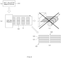
FIG. 6 is a conceptual view illustrating some processes in the method for manufacturing the electrode according to Embodiment 2 of the present invention. -
FIG. 7 is a view illustrating a unit electrode inspection process in the method for manufacturing the electrode according to Embodiment 2 of the present invention. - Hereinafter, preferred embodiments of the present invention will be described in detail with reference to the accompanying drawings so that those of ordinary skill in the art can easily carry out the present invention. However, the present invention may be implemented in several different forms and is not limited or restricted by the following examples.
- In order to clearly explain the present invention, detailed descriptions of portions that are irrelevant to the description or related known technologies that may unnecessarily obscure the gist of the present invention have been omitted, and in the present specification, reference symbols are added to components in each drawing. In this case, the same or similar reference numerals are assigned to the same or similar elements throughout the specification.
- Also, terms or words used in this specification and claims should not be restrictively interpreted as ordinary meanings or dictionary-based meanings, but should be interpreted as meanings and concepts conforming to the scope of the present invention on the basis of the principle that an inventor can properly define the concept of a term to describe and explain his or her invention in the best ways.
-
FIG. 3 is a view illustrating an electrode according to Embodiment 1 of the present invention.FIG. 4 is a plan view illustrating a state in which a unit electrode of the electrode is attached to a base collector having various sizes and shapes according to Embodiment 1 of the present invention. - Referring to
FIG. 3 , anelectrode 100 according to Embodiment 1 of the present invention includes abase collector 110 and aunit electrode 120. Thebase electrode 100 is a collector made of a metal material and forms the lowest base surface of theelectrode 100. Theunit electrode 120 may be attached to thebase collector 110. Theunit electrode 120 is made of a metal material and includes aunit collector 121 having a size less than that of thebase collector 110 and an electrodeactive material 122 applied to one surface of theunit collector 121. Here, theunit collector 121 may also have a plate shape. Thebase collector 110 may also have a plate shape. Theunit electrode 120 may be provided in plurality. In addition, each of theunit electrodes 120 may have a block shape. -
FIG. 3(b) illustrates a state in which oneunit electrode 120 is attached to onebase collector 110. Of course, in theelectrode 100 according to Embodiment 1 of the present invention, the plurality ofunit electrodes 120 are attached to thebase collector 110 to form theelectrode 100. However, for convenience of description,FIG. 3(b) illustrates a state in which only oneunit electrode 120 is attached to thebase collector 110. In addition,FIG. 3(a) illustrates a side view when a side portion of theelectrode 100 is viewed at a position at which theunit electrode 120 illustrated inFIG. 3(b) is attached. Referring toFIG. 3(a) , thebase collector 110 is disposed at the lowest position, and theunit electrode 120 is attached on the base collector (inFIG. 3(a) , theunit electrode 120 is indicated by a dotted line box). - In addition, the
unit electrode 120 may also include aunit collector 121 disposed at a lower side and an electrodeactive material 122 applied to a top surface of the unit collector. Here, the electrodeactive material 122 may be applied on an entire top surface of theunit collector 121. The electrodeactive material 122 may be applied to the top surface of theunit collector 121, and a bottom surface of theunit collector 121 may be attached to the base collector. - When the
electrode 100 is manufactured in this manner, a bending phenomenon of coating of the electrodeactive material 122 or a delamination or creaking phenomenon of the electrodeactive material 122 may be prevented from occurring at the electrode. - Specifically, in the existing electrode, as the electrode coated with the electrode active material is wound on a roll, the bending phenomenon of the electrode active material coating or the delamination or creaking phenomenon of the electrode active material occurs at the winding part of the roll. However, in the case of the present invention, since the block-shaped
unit electrode 120 needs only to be attached to the plate-shapedbase collector 110, the tension due to the bending does not act on the electrodeactive material 122 to prevent the delamination or cracking phenomenon of the electrodeactive material 122 from occurring. - Referring to
FIG. 4 , theelectrode 100 according to Embodiment 1 of the present invention may have a configuration in which a plurality ofunit electrodes 120 are arranged to form columns and rows on one surface of thebase collector 110. In addition, the configuration in which the plurality ofunit electrodes 120 are arranged may correspond to that of thebase collector 110. When formed in this manner, theelectrode 100 having various shapes and sizes may be easily manufactured.FIG. 4 illustrates an example in which three types ofelectrodes 100 are manufactured. As illustrated inFIG. 4 , even if shapes of theelectrodes 100 are different from each other, since all the electrodes are capable of being manufactured by attaching thesame unit electrode 120, theelectrodes 100 may be more efficiently manufactured. - In addition, in the process according to the related art, since the process of cutting the
electrode 100 is performed after applying the electrodeactive material 122, the delamination phenomenon of the electrodeactive material 122 occurs in the cutting process. However, in case of the present invention, since the cutting is performed in a state of the collector, on which the electrode active material is not applied, and the process of cutting the electrode is not performed after applying the electrodeactive material 122, the delamination phenomenon of the electrodeactive material 122 may be prevented from occurring in the cutting process. - Referring to
FIGS. 3 and4 , theelectrode 100 according to Embodiment 1 of the present invention may further include anelectrode tab part 111 extending from one end of thebase collector 110 for convenience in manufacturing. As described above, when theelectrode tab part 111 is continuously formed on the collector, a process of attaching the electrode tab may be omitted, and thus, production efficiency may be further improved. -
FIG. 5 is a diagram illustrating a main process in a method for manufacturing an electrode according to Embodiment 2 of the present invention.FIG. 6 is a conceptual view illustrating some processes in the method for manufacturing the electrode according to Embodiment 2 of the present invention.FIG. 7 is a view illustrating a unit electrode inspection process in the method for manufacturing the electrode according to Embodiment 2 of the present invention. - Embodiment 2 of the present invention is different from Embodiment 1 in that Embodiment 2 relates to a method for manufacturing the electrode according to Embodiment 1.
- The contents that are duplicated with Embodiment 1 will be omitted as much as possible, and Embodiment 2 will be described with a focus on the differences. That is, it is obvious that the contents that are not described in Embodiment 2 may be regarded as the contents of Embodiment 1 if necessary.
- Referring to
FIG. 5 , a method of manufacturing anelectrode 100 according to Embodiment 2 of the present invention may include a unit collector manufacturing process (S10), a unit electrode manufacturing process (S20), and a unit electrode attachment process (S30). - The unit collector manufacturing process S10 may be a process of manufacturing a
unit collector 121 by cutting a collector base material made of a metal material to have a predetermined area and shape based on a plan view. The size and shape of theunit collector 121 may be determined according to the purpose and situation of the design. Mass production of theunit collector 121 may be performed according to the size and shape of theunit collector 121, which are determined once. The plurality ofunit collectors 121 manufactured in this manner may have the same shape and size as each other. In addition, for convenience of the attachment, theunit collector 121 may be formed in a rectangular (or square) shape and may also be formed in a thin plate shape. - The unit electrode manufacturing process (S20) may be a process of applying an electrode active material on one surface of the
unit collector 121 to manufacture aunit electrode 120. As illustrated in (b) ofFIG. 6 , a process of applying an electrodeactive material 122 may be performed while the plurality ofunit collectors 121 having the same shape are transferred on a transfer belt B. - In addition, the unit electrode attachment process (S30) may be a process of attaching the
electrode 120, which is previously manufactured, on thebase collector 110 made of a metal material and having a size greater than that of the unit collector 121 (seeFIG. 4 ). In the unit electrode attachment process (S30), a plurality ofunit electrodes 120, each of which has a block shape, may be attached to thebase collector 110. - In this case, the attachment (or adhesion) between the
base collector 110 and theunit electrode 120 may be performed through a vaporized foil actuator welding (VFAW) method. When theunit electrode 120 adheres to thebase collector 110 through the vaporized foil actuator welding, the adhesion between conductive metals having low resistance may be achieved. - The plurality of
unit electrodes 120 may be arranged to form columns and rows on one surface of thebase collector 110. In addition, the configuration in which the plurality ofunit electrodes 120 are arranged may correspond to that of thebase collector 110. When formed in this manner, theelectrode 100 having various shapes and sizes may be easily manufactured. - Referring to
FIG. 6 , a unit electrode storage process (S25) of stacking and storing theunit electrodes 120 may be further performed between the unit electrode manufacturing process (S20) and the unit electrode attachment process (S30).FIG. 6(d) illustrates a method in which theunit electrodes 120 are stacked and stored in the unit electrode storage process (S25). - According to the related art, as illustrated in
FIG. 6(c) , as the electrode coated with the electrode active material is wound on theroll 30, the bending phenomenon of the electrode active material or the delamination phenomenon of the electrode active material occurred at the winding part of the roll 300, and also, the cracking phenomenon occurred in addition to the bending or delamination phenomenon. However, as illustrated inFIGS. 6(a), (b) and (d) , in case of the present invention, since only the processes of transferring, stacking, and storing the block-shaped unit electrodes are performed, and the process of winding the unit electrode on the roll is not performed, the delamination or creaking phenomenon of the electrodeactive material 122 may be prevented from occurring. Even after the storage process, since there is only the process of attaching the unit electrode on the base collector, the delamination phenomenon of the electrode active material may not occur during the entire processes. - In addition, referring to
FIG. 7 , the method of manufacturing the electrode according to Embodiment 2 of the present invention may further include a unit electrode inspection process (S23) of inspecting whether theunit electrode 120 is defective to discard thedefective unit electrode 120 between the unit electrode manufacturing process (S20) and the unit electrode storage process (S25). The unit electrode inspection process (S23) may be performed on theunit electrode 120 manufactured in the unit electrode manufacturing process (S20). Whether theelectrode 100 is defective may be performed immediately after the unit electrode manufacturing process (S20) is completed. In addition, with respect to theunit electrode 120 that is determined to be defective, only oneunit electrode 120 that is determined to be defective may be discarded. - In the related art, since the
electrode 100 is wound in the roll shape, when a specific portion of theelectrode 100 is defective, theentire roll 30 has to be discarded. However, in the method for manufacturing the electrode according to Embodiment 2 of the present invention, only oneunit electrode 120 that is determined to be defective may be discarded to prevent production costs from increasing due to the discarding of the entire roll. As a result, the result of productivity improvement may also be obtained. - Example 3 of the present invention is different from Example 1 in that Embodiment 3 relates to an electrode assembly manufactured using the electrode according to Embodiment 1.
- The contents that are duplicated with Embodiment 1 will be omitted as much as possible, and Embodiment 3 will be described with a focus on the differences. That is, it is obvious that the contents that are not described in Embodiment 3 may be regarded as the contents of Embodiment 1 if necessary.
- An electrode assembly (not shown) according to Example 3 of the present invention may be an electrode assembly formed by alternately stacking separators on the
electrodes 100 manufactured in Embodiment 1. - That is, in the electrode assembly according to Embodiment 3 of the present invention, the
electrode 100 may include abase collector 110 made of a metal material and aunit electrode 120 attached to thebase collector 110. - Here, the
unit electrode 120 may be made of a metal material and include aunit collector 121 having a size less than that of thebase collector 110 and an electrodeactive material 122 applied to one surface of theunit collector 121. -
FIG. 4 illustrates theelectrode 100 formed by attaching a plurality ofunit electrodes 120 to thebase collector 110. Thus, when theelectrodes 100 and the separators are alternately stacked, the electrode assembly according to Example 3 of the present invention may be manufactured. - While the embodiments of the present invention have been described with reference to the specific embodiments, it will be apparent to those skilled in the art that various changes and modifications may be made without departing from the spirit and scope of the invention as defined in the following claims.
-
- 100:
- Electrode
- 110:
- Base collector
- 111:
- Electrode tab part
- 120:
- Unit electrode
- 121:
- Unit collector
- 122:
- Electrode active material
- B:
- Transfer belt
Claims (14)
- An electrode comprising:a base collector made of a metal material; anda unit electrode attached to the base collector,wherein the unit electrode comprises:a unit collector made of a metal material and having a size less than that of the base collector; andan electrode active material applied on one surface of the unit collector.
- The electrode of claim 1, wherein the unit electrode is provided in plurality, and
each of the unit electrodes has a block shape. - The electrode of claim 1, wherein the base collector has a plate shape.
- The electrode of claim 1, wherein the unit collector has a plate shape, and
the electrode active material is applied to an entire top surface of the unit collector. - The electrode of claim 2, wherein the plurality of unit electrodes are arranged to form columns and rows on one surface of the base collector.
- The electrode of claim 2, wherein a configuration in which the plurality of unit electrodes are arranged corresponds to that of the base collector.
- The electrode of claim 1, further comprising an electrode tab part extending from one end of the base collector.
- A method for manufacturing an electrode, the method comprising:a unit collector manufacturing process (S10) of cutting a collector base material made of a metal material to have a predetermined area and shape on a plan view, thereby manufacturing a unit collector;a unit electrode manufacturing process (S20) of applying an electrode active material on one surface of the unit collector to manufacture a unit electrode; anda unit electrode attachment process (S30) of attaching the unit electrode on a base collector made of a metal material and having a size greater than that of the unit collector.
- The method of claim 8, wherein, in the unit electrode attachment process, the unit electrode having a block shape is attached in plurality on the base collector.
- The method of claim 9, wherein, in the unit electrode attachment process, the plurality of unit electrodes are arranged to form columns and rows on one surface of the base collector.
- The method of claim 9, wherein, in the unit electrode attachment process, the plurality of unit electrodes are arranged so that the configuration formed by arranging the plurality of unit electrodes corresponds to that of the base collector.
- The method of claim 8, further comprising a unit electrode storage process (S25) of stacking and storing the unit electrodes between the unit electrode manufacturing process (S20) and the unit electrode attachment process (S30).
- The method of claim 12, further comprising a unit electrode inspection process (S23) of inspecting whether the unit electrode is defective to discard the defective unit electrode between the unit electrode manufacturing process (S20) and the unit electrode storage process (S25).
- An electrode assembly, in which electrodes and separators are alternately stacked, the electrode assembly,wherein each of the electrodes comprises:a base collector made of a metal material; anda unit electrode attached to the base collector,wherein the unit electrode comprises:a unit collector made of a metal material and having a size less than that of the base collector; andan electrode active material applied on one surface of the unit collector.
Applications Claiming Priority (3)
| Application Number | Priority Date | Filing Date | Title |
|---|---|---|---|
| KR20210049475 | 2021-04-15 | ||
| KR1020220014452A KR102954923B1 (en) | 2021-04-15 | 2022-02-03 | Electrode and manufacturing method for the same |
| PCT/KR2022/005240 WO2022220526A1 (en) | 2021-04-15 | 2022-04-12 | Electrode and method for manufacturing electrode |
Publications (3)
| Publication Number | Publication Date |
|---|---|
| EP4220747A1 true EP4220747A1 (en) | 2023-08-02 |
| EP4220747A4 EP4220747A4 (en) | 2024-07-24 |
| EP4220747B1 EP4220747B1 (en) | 2025-10-22 |
Family
ID=83640476
Family Applications (1)
| Application Number | Title | Priority Date | Filing Date |
|---|---|---|---|
| EP22788382.4A Active EP4220747B1 (en) | 2021-04-15 | 2022-04-12 | Electrode and method for manufacturing the same |
Country Status (5)
| Country | Link |
|---|---|
| US (1) | US20240006616A1 (en) |
| EP (1) | EP4220747B1 (en) |
| CN (1) | CN116368632B (en) |
| ES (1) | ES3054405T3 (en) |
| WO (1) | WO2022220526A1 (en) |
Families Citing this family (1)
| Publication number | Priority date | Publication date | Assignee | Title |
|---|---|---|---|---|
| US20240006616A1 (en) * | 2021-04-15 | 2024-01-04 | Lg Energy Solution, Ltd. | Electrode and Method for Manufacturing the Same |
Family Cites Families (24)
| Publication number | Priority date | Publication date | Assignee | Title |
|---|---|---|---|---|
| JP2005011660A (en) * | 2003-06-18 | 2005-01-13 | Nissan Motor Co Ltd | Secondary battery electrode, method of manufacturing the same, and secondary battery using the same |
| JP2009199973A (en) * | 2008-02-25 | 2009-09-03 | Panasonic Corp | Collector for nonaqueous secondary battery, electrode plate for nonaqueous secondary battery using the same, and nonaqueous secondary battery |
| JP2010212143A (en) * | 2009-03-11 | 2010-09-24 | Nissan Motor Co Ltd | Electrode manufacturing method and electrode manufacturing device |
| JP5077315B2 (en) * | 2009-09-30 | 2012-11-21 | 日産自動車株式会社 | Secondary battery electrode |
| US8551660B2 (en) * | 2009-11-30 | 2013-10-08 | Tai-Her Yang | Reserve power supply with electrode plates joined to auxiliary conductors |
| US8440355B2 (en) * | 2010-01-21 | 2013-05-14 | Tai-Her Yang | Equalizing electrode plate with insulated split-flow conductive structure |
| KR101199125B1 (en) * | 2010-09-02 | 2012-11-09 | 삼성에스디아이 주식회사 | Electrode assembly including bending portions and secondary battery having the same |
| DE102011008706A1 (en) * | 2011-01-17 | 2012-07-19 | Li-Tec Battery Gmbh | Exothermic component, electrode assembly, electric power cell and cell assembly, and method for manufacturing and method of driving |
| JP6267910B2 (en) * | 2012-10-05 | 2018-01-24 | 株式会社半導体エネルギー研究所 | Method for producing negative electrode for lithium ion secondary battery |
| CN103490089A (en) * | 2013-06-17 | 2014-01-01 | 中国科学院物理研究所 | Electrode subassembly, preparation method thereof and lithium secondary battery |
| CN104466229A (en) * | 2013-09-25 | 2015-03-25 | 华为技术有限公司 | Flexible lithium secondary battery and preparation method thereof |
| CN105592989B (en) * | 2013-09-30 | 2018-10-12 | 日产自动车株式会社 | Metal foil cutting device |
| KR101675950B1 (en) * | 2014-05-08 | 2016-11-14 | 주식회사 엘지화학 | Electrode Assembly Having Alternatively-arranged Noncoating Parts and Coating Parts and Flexible Battery Cell Comprising the Same |
| KR101717197B1 (en) * | 2014-05-22 | 2017-03-16 | 주식회사 엘지화학 | Flexible Battery Employed with a Plurality of Unit Cells |
| US10122010B2 (en) * | 2014-07-11 | 2018-11-06 | Semiconductor Energy Laboratory Co., Ltd. | Secondary battery and electronic device including the same |
| CN108886125A (en) * | 2016-02-01 | 2018-11-23 | 密执安州立大学董事会 | Segmented cell architecture for solid-state batteries |
| CN107154499B (en) * | 2017-04-14 | 2020-05-15 | 宁德时代新能源科技股份有限公司 | A lithium battery containing current collector and preparation method thereof |
| JP6923401B2 (en) * | 2017-09-14 | 2021-08-18 | 株式会社エンビジョンAescジャパン | Stacked batteries and battery modules |
| JP7093367B2 (en) * | 2017-11-30 | 2022-06-29 | パナソニックホールディングス株式会社 | Non-aqueous electrolyte secondary battery |
| JP7289072B2 (en) * | 2018-05-31 | 2023-06-09 | パナソニックIpマネジメント株式会社 | lithium secondary battery |
| CN109004283B (en) * | 2018-07-26 | 2022-02-01 | 京东方科技集团股份有限公司 | All-solid-state lithium battery and preparation method thereof |
| KR102363870B1 (en) * | 2020-11-13 | 2022-02-18 | 주식회사 디에이테크놀로지 | Apparatus for Cutting Electrode for Secondary Battery |
| KR102954923B1 (en) * | 2021-04-15 | 2026-04-21 | 주식회사 엘지에너지솔루션 | Electrode and manufacturing method for the same |
| US20240006616A1 (en) * | 2021-04-15 | 2024-01-04 | Lg Energy Solution, Ltd. | Electrode and Method for Manufacturing the Same |
-
2022
- 2022-04-12 US US18/035,368 patent/US20240006616A1/en active Pending
- 2022-04-12 EP EP22788382.4A patent/EP4220747B1/en active Active
- 2022-04-12 CN CN202280007219.7A patent/CN116368632B/en active Active
- 2022-04-12 ES ES22788382T patent/ES3054405T3/en active Active
- 2022-04-12 WO PCT/KR2022/005240 patent/WO2022220526A1/en not_active Ceased
Also Published As
| Publication number | Publication date |
|---|---|
| US20240006616A1 (en) | 2024-01-04 |
| EP4220747A4 (en) | 2024-07-24 |
| CN116368632B (en) | 2026-02-27 |
| ES3054405T3 (en) | 2026-02-03 |
| EP4220747B1 (en) | 2025-10-22 |
| WO2022220526A1 (en) | 2022-10-20 |
| CN116368632A (en) | 2023-06-30 |
Similar Documents
| Publication | Publication Date | Title |
|---|---|---|
| EP3518306B1 (en) | Secondary battery and manufacturing method thereof | |
| US9083007B2 (en) | Continuous prismatic cell stacking system and method | |
| US8702818B2 (en) | Method of manufacturing an electrode assembly for a rechargeable battery | |
| US9385395B2 (en) | Continuous prismatic cell stacking system and method | |
| EP2985805B1 (en) | Curved secondary battery and method of manufacturing the same | |
| US8673476B2 (en) | Electrode assembly having stable lead-tap joint and electrochemical cell containing them | |
| US11552357B2 (en) | Secondary battery and manufacturing method therefor | |
| EP2866290B1 (en) | Electrode assembly for polymer secondary battery cell | |
| EP4379894A1 (en) | In-line manufacturing apparatus for lithium metal battery | |
| KR102403673B1 (en) | Electrode assembly, secondary battery and manufacturing method of electrode assembly | |
| KR100928128B1 (en) | Secondary battery pouch manufacturing method and secondary battery pouch | |
| KR20130103569A (en) | Method and device for producing an electrochemical energy store | |
| EP4220747B1 (en) | Electrode and method for manufacturing the same | |
| US20240283104A1 (en) | Electrode Tab and Method for Cutting Electrode Tab | |
| US9356294B2 (en) | Secondary battery including collectors with pores and manufacturing method thereof | |
| KR20210052050A (en) | Method for manufacturing electrode plate and electrode plate thereby | |
| KR102954923B1 (en) | Electrode and manufacturing method for the same | |
| KR102914055B1 (en) | The Apparatus And The Method For Manufacturing Unit Cell | |
| KR20170022697A (en) | Electrode assembly | |
| KR102920239B1 (en) | Method for manufacturing electrode assembly | |
| US20230411806A1 (en) | Secondary battery | |
| KR102340101B1 (en) | Battery and method for manufcturing the same | |
| US20250329894A1 (en) | All-solid-state battery | |
| US20240021962A1 (en) | Electrode tab, electrode assembly and secondary battery including the same | |
| JP7104482B2 (en) | Rechargeable battery stack |
Legal Events
| Date | Code | Title | Description |
|---|---|---|---|
| STAA | Information on the status of an ep patent application or granted ep patent |
Free format text: STATUS: THE INTERNATIONAL PUBLICATION HAS BEEN MADE |
|
| PUAI | Public reference made under article 153(3) epc to a published international application that has entered the european phase |
Free format text: ORIGINAL CODE: 0009012 |
|
| STAA | Information on the status of an ep patent application or granted ep patent |
Free format text: STATUS: REQUEST FOR EXAMINATION WAS MADE |
|
| 17P | Request for examination filed |
Effective date: 20230428 |
|
| AK | Designated contracting states |
Kind code of ref document: A1 Designated state(s): AL AT BE BG CH CY CZ DE DK EE ES FI FR GB GR HR HU IE IS IT LI LT LU LV MC MK MT NL NO PL PT RO RS SE SI SK SM TR |
|
| A4 | Supplementary search report drawn up and despatched |
Effective date: 20240620 |
|
| DAV | Request for validation of the european patent (deleted) | ||
| DAX | Request for extension of the european patent (deleted) | ||
| RIC1 | Information provided on ipc code assigned before grant |
Ipc: H01M 10/0585 20100101ALI20240614BHEP Ipc: H01M 10/052 20100101ALI20240614BHEP Ipc: H01M 4/70 20060101ALI20240614BHEP Ipc: H01M 4/64 20060101ALI20240614BHEP Ipc: H01M 4/139 20100101ALI20240614BHEP Ipc: H01M 4/13 20100101ALI20240614BHEP Ipc: H01M 10/04 20060101ALI20240614BHEP Ipc: H01M 4/66 20060101ALI20240614BHEP Ipc: H01M 4/04 20060101ALI20240614BHEP Ipc: H01M 4/02 20060101AFI20240614BHEP |
|
| STAA | Information on the status of an ep patent application or granted ep patent |
Free format text: STATUS: EXAMINATION IS IN PROGRESS |
|
| 17Q | First examination report despatched |
Effective date: 20250128 |
|
| GRAP | Despatch of communication of intention to grant a patent |
Free format text: ORIGINAL CODE: EPIDOSNIGR1 |
|
| STAA | Information on the status of an ep patent application or granted ep patent |
Free format text: STATUS: GRANT OF PATENT IS INTENDED |
|
| GRAS | Grant fee paid |
Free format text: ORIGINAL CODE: EPIDOSNIGR3 |
|
| INTG | Intention to grant announced |
Effective date: 20250813 |
|
| GRAA | (expected) grant |
Free format text: ORIGINAL CODE: 0009210 |
|
| STAA | Information on the status of an ep patent application or granted ep patent |
Free format text: STATUS: THE PATENT HAS BEEN GRANTED |
|
| AK | Designated contracting states |
Kind code of ref document: B1 Designated state(s): AL AT BE BG CH CY CZ DE DK EE ES FI FR GB GR HR HU IE IS IT LI LT LU LV MC MK MT NL NO PL PT RO RS SE SI SK SM TR |
|
| P01 | Opt-out of the competence of the unified patent court (upc) registered |
Free format text: CASE NUMBER: UPC_APP_6750_4220747/2025 Effective date: 20250911 |
|
| REG | Reference to a national code |
Ref country code: CH Ref legal event code: F10 Free format text: ST27 STATUS EVENT CODE: U-0-0-F10-F00 (AS PROVIDED BY THE NATIONAL OFFICE) Effective date: 20251022 Ref country code: GB Ref legal event code: FG4D |
|
| REG | Reference to a national code |
Ref country code: DE Ref legal event code: R096 Ref document number: 602022023562 Country of ref document: DE |
|
| REG | Reference to a national code |
Ref country code: IE Ref legal event code: FG4D |
|
| REG | Reference to a national code |
Ref country code: ES Ref legal event code: FG2A Ref document number: 3054405 Country of ref document: ES Kind code of ref document: T3 Effective date: 20260203 |
|
| REG | Reference to a national code |
Ref country code: NL Ref legal event code: MP Effective date: 20251022 |
|
| PG25 | Lapsed in a contracting state [announced via postgrant information from national office to epo] |
Ref country code: NL Free format text: LAPSE BECAUSE OF FAILURE TO SUBMIT A TRANSLATION OF THE DESCRIPTION OR TO PAY THE FEE WITHIN THE PRESCRIBED TIME-LIMIT Effective date: 20251022 |
|
| PGFP | Annual fee paid to national office [announced via postgrant information from national office to epo] |
Ref country code: GB Payment date: 20260324 Year of fee payment: 5 |
|
| REG | Reference to a national code |
Ref country code: LT Ref legal event code: MG9D |
|
| PG25 | Lapsed in a contracting state [announced via postgrant information from national office to epo] |
Ref country code: NO Free format text: LAPSE BECAUSE OF FAILURE TO SUBMIT A TRANSLATION OF THE DESCRIPTION OR TO PAY THE FEE WITHIN THE PRESCRIBED TIME-LIMIT Effective date: 20260122 |
|
| PG25 | Lapsed in a contracting state [announced via postgrant information from national office to epo] |
Ref country code: AT Free format text: LAPSE BECAUSE OF FAILURE TO SUBMIT A TRANSLATION OF THE DESCRIPTION OR TO PAY THE FEE WITHIN THE PRESCRIBED TIME-LIMIT Effective date: 20251022 Ref country code: HR Free format text: LAPSE BECAUSE OF FAILURE TO SUBMIT A TRANSLATION OF THE DESCRIPTION OR TO PAY THE FEE WITHIN THE PRESCRIBED TIME-LIMIT Effective date: 20251022 Ref country code: FI Free format text: LAPSE BECAUSE OF FAILURE TO SUBMIT A TRANSLATION OF THE DESCRIPTION OR TO PAY THE FEE WITHIN THE PRESCRIBED TIME-LIMIT Effective date: 20251022 |
|
| PGFP | Annual fee paid to national office [announced via postgrant information from national office to epo] |
Ref country code: BE Payment date: 20260323 Year of fee payment: 5 |
|
| REG | Reference to a national code |
Ref country code: AT Ref legal event code: MK05 Ref document number: 1850007 Country of ref document: AT Kind code of ref document: T Effective date: 20251022 |
|
| PG25 | Lapsed in a contracting state [announced via postgrant information from national office to epo] |
Ref country code: RS Free format text: LAPSE BECAUSE OF FAILURE TO SUBMIT A TRANSLATION OF THE DESCRIPTION OR TO PAY THE FEE WITHIN THE PRESCRIBED TIME-LIMIT Effective date: 20260122 |
|
| PG25 | Lapsed in a contracting state [announced via postgrant information from national office to epo] |
Ref country code: IS Free format text: LAPSE BECAUSE OF FAILURE TO SUBMIT A TRANSLATION OF THE DESCRIPTION OR TO PAY THE FEE WITHIN THE PRESCRIBED TIME-LIMIT Effective date: 20260222 |
|
| PGFP | Annual fee paid to national office [announced via postgrant information from national office to epo] |
Ref country code: FR Payment date: 20260323 Year of fee payment: 5 |
|
| PG25 | Lapsed in a contracting state [announced via postgrant information from national office to epo] |
Ref country code: PT Free format text: LAPSE BECAUSE OF FAILURE TO SUBMIT A TRANSLATION OF THE DESCRIPTION OR TO PAY THE FEE WITHIN THE PRESCRIBED TIME-LIMIT Effective date: 20260223 |
|
| PG25 | Lapsed in a contracting state [announced via postgrant information from national office to epo] |
Ref country code: PL Free format text: LAPSE BECAUSE OF FAILURE TO SUBMIT A TRANSLATION OF THE DESCRIPTION OR TO PAY THE FEE WITHIN THE PRESCRIBED TIME-LIMIT Effective date: 20251022 |
|
| PG25 | Lapsed in a contracting state [announced via postgrant information from national office to epo] |
Ref country code: LV Free format text: LAPSE BECAUSE OF FAILURE TO SUBMIT A TRANSLATION OF THE DESCRIPTION OR TO PAY THE FEE WITHIN THE PRESCRIBED TIME-LIMIT Effective date: 20251022 |
|
| PG25 | Lapsed in a contracting state [announced via postgrant information from national office to epo] |
Ref country code: BG Free format text: LAPSE BECAUSE OF FAILURE TO SUBMIT A TRANSLATION OF THE DESCRIPTION OR TO PAY THE FEE WITHIN THE PRESCRIBED TIME-LIMIT Effective date: 20251022 |