EP4220556A1 - Image processing apparatus, image processing method, program, and storage medium - Google Patents
Image processing apparatus, image processing method, program, and storage medium Download PDFInfo
- Publication number
- EP4220556A1 EP4220556A1 EP23151390.4A EP23151390A EP4220556A1 EP 4220556 A1 EP4220556 A1 EP 4220556A1 EP 23151390 A EP23151390 A EP 23151390A EP 4220556 A1 EP4220556 A1 EP 4220556A1
- Authority
- EP
- European Patent Office
- Prior art keywords
- image
- cutting
- locus
- moving image
- region
- Prior art date
- Legal status (The legal status is an assumption and is not a legal conclusion. Google has not performed a legal analysis and makes no representation as to the accuracy of the status listed.)
- Pending
Links
- 238000012545 processing Methods 0.000 title claims abstract description 127
- 238000003860 storage Methods 0.000 title claims description 31
- 238000003672 processing method Methods 0.000 title claims description 5
- 238000005520 cutting process Methods 0.000 claims abstract description 48
- 238000001514 detection method Methods 0.000 claims abstract description 26
- 238000009795 derivation Methods 0.000 claims abstract description 15
- 238000000034 method Methods 0.000 description 29
- 230000006870 function Effects 0.000 description 13
- 238000010586 diagram Methods 0.000 description 7
- 240000004050 Pentaglottis sempervirens Species 0.000 description 3
- 235000004522 Pentaglottis sempervirens Nutrition 0.000 description 3
- 238000004458 analytical method Methods 0.000 description 3
- 238000004590 computer program Methods 0.000 description 3
- 230000007123 defense Effects 0.000 description 3
- 238000009826 distribution Methods 0.000 description 3
- 239000000284 extract Substances 0.000 description 3
- 238000012935 Averaging Methods 0.000 description 2
- 238000013135 deep learning Methods 0.000 description 2
- 238000003384 imaging method Methods 0.000 description 2
- 238000010801 machine learning Methods 0.000 description 2
- 230000003287 optical effect Effects 0.000 description 2
- 238000004091 panning Methods 0.000 description 2
- 230000009466 transformation Effects 0.000 description 2
- 230000006399 behavior Effects 0.000 description 1
- 238000004364 calculation method Methods 0.000 description 1
- 230000000295 complement effect Effects 0.000 description 1
- 238000012937 correction Methods 0.000 description 1
- 230000003247 decreasing effect Effects 0.000 description 1
- 230000001934 delay Effects 0.000 description 1
- 238000011161 development Methods 0.000 description 1
- 238000000605 extraction Methods 0.000 description 1
- 238000009499 grossing Methods 0.000 description 1
- 238000012417 linear regression Methods 0.000 description 1
- 229910044991 metal oxide Inorganic materials 0.000 description 1
- 150000004706 metal oxides Chemical class 0.000 description 1
- 239000004065 semiconductor Substances 0.000 description 1
- 108020001568 subdomains Proteins 0.000 description 1
- 230000001131 transforming effect Effects 0.000 description 1
Images


Classifications
-
- G—PHYSICS
- G06—COMPUTING; CALCULATING OR COUNTING
- G06T—IMAGE DATA PROCESSING OR GENERATION, IN GENERAL
- G06T7/00—Image analysis
- G06T7/70—Determining position or orientation of objects or cameras
- G06T7/73—Determining position or orientation of objects or cameras using feature-based methods
-
- G—PHYSICS
- G06—COMPUTING; CALCULATING OR COUNTING
- G06T—IMAGE DATA PROCESSING OR GENERATION, IN GENERAL
- G06T7/00—Image analysis
- G06T7/10—Segmentation; Edge detection
- G06T7/11—Region-based segmentation
-
- G—PHYSICS
- G06—COMPUTING; CALCULATING OR COUNTING
- G06T—IMAGE DATA PROCESSING OR GENERATION, IN GENERAL
- G06T7/00—Image analysis
- G06T7/20—Analysis of motion
- G06T7/246—Analysis of motion using feature-based methods, e.g. the tracking of corners or segments
-
- G—PHYSICS
- G06—COMPUTING; CALCULATING OR COUNTING
- G06F—ELECTRIC DIGITAL DATA PROCESSING
- G06F3/00—Input arrangements for transferring data to be processed into a form capable of being handled by the computer; Output arrangements for transferring data from processing unit to output unit, e.g. interface arrangements
- G06F3/01—Input arrangements or combined input and output arrangements for interaction between user and computer
- G06F3/048—Interaction techniques based on graphical user interfaces [GUI]
- G06F3/0484—Interaction techniques based on graphical user interfaces [GUI] for the control of specific functions or operations, e.g. selecting or manipulating an object, an image or a displayed text element, setting a parameter value or selecting a range
-
- G—PHYSICS
- G06—COMPUTING; CALCULATING OR COUNTING
- G06T—IMAGE DATA PROCESSING OR GENERATION, IN GENERAL
- G06T7/00—Image analysis
- G06T7/10—Segmentation; Edge detection
- G06T7/187—Segmentation; Edge detection involving region growing; involving region merging; involving connected component labelling
-
- G—PHYSICS
- G06—COMPUTING; CALCULATING OR COUNTING
- G06T—IMAGE DATA PROCESSING OR GENERATION, IN GENERAL
- G06T7/00—Image analysis
- G06T7/20—Analysis of motion
-
- G—PHYSICS
- G06—COMPUTING; CALCULATING OR COUNTING
- G06T—IMAGE DATA PROCESSING OR GENERATION, IN GENERAL
- G06T7/00—Image analysis
- G06T7/70—Determining position or orientation of objects or cameras
-
- G—PHYSICS
- G06—COMPUTING; CALCULATING OR COUNTING
- G06V—IMAGE OR VIDEO RECOGNITION OR UNDERSTANDING
- G06V10/00—Arrangements for image or video recognition or understanding
- G06V10/20—Image preprocessing
- G06V10/25—Determination of region of interest [ROI] or a volume of interest [VOI]
-
- G—PHYSICS
- G06—COMPUTING; CALCULATING OR COUNTING
- G06V—IMAGE OR VIDEO RECOGNITION OR UNDERSTANDING
- G06V10/00—Arrangements for image or video recognition or understanding
- G06V10/40—Extraction of image or video features
-
- G—PHYSICS
- G06—COMPUTING; CALCULATING OR COUNTING
- G06V—IMAGE OR VIDEO RECOGNITION OR UNDERSTANDING
- G06V10/00—Arrangements for image or video recognition or understanding
- G06V10/40—Extraction of image or video features
- G06V10/44—Local feature extraction by analysis of parts of the pattern, e.g. by detecting edges, contours, loops, corners, strokes or intersections; Connectivity analysis, e.g. of connected components
-
- G—PHYSICS
- G06—COMPUTING; CALCULATING OR COUNTING
- G06V—IMAGE OR VIDEO RECOGNITION OR UNDERSTANDING
- G06V20/00—Scenes; Scene-specific elements
- G06V20/40—Scenes; Scene-specific elements in video content
- G06V20/41—Higher-level, semantic clustering, classification or understanding of video scenes, e.g. detection, labelling or Markovian modelling of sport events or news items
- G06V20/42—Higher-level, semantic clustering, classification or understanding of video scenes, e.g. detection, labelling or Markovian modelling of sport events or news items of sport video content
-
- H—ELECTRICITY
- H04—ELECTRIC COMMUNICATION TECHNIQUE
- H04N—PICTORIAL COMMUNICATION, e.g. TELEVISION
- H04N23/00—Cameras or camera modules comprising electronic image sensors; Control thereof
- H04N23/60—Control of cameras or camera modules
- H04N23/66—Remote control of cameras or camera parts, e.g. by remote control devices
- H04N23/661—Transmitting camera control signals through networks, e.g. control via the Internet
-
- H—ELECTRICITY
- H04—ELECTRIC COMMUNICATION TECHNIQUE
- H04N—PICTORIAL COMMUNICATION, e.g. TELEVISION
- H04N23/00—Cameras or camera modules comprising electronic image sensors; Control thereof
- H04N23/60—Control of cameras or camera modules
- H04N23/695—Control of camera direction for changing a field of view, e.g. pan, tilt or based on tracking of objects
-
- G—PHYSICS
- G06—COMPUTING; CALCULATING OR COUNTING
- G06T—IMAGE DATA PROCESSING OR GENERATION, IN GENERAL
- G06T2207/00—Indexing scheme for image analysis or image enhancement
- G06T2207/10—Image acquisition modality
- G06T2207/10016—Video; Image sequence
-
- G—PHYSICS
- G06—COMPUTING; CALCULATING OR COUNTING
- G06T—IMAGE DATA PROCESSING OR GENERATION, IN GENERAL
- G06T2207/00—Indexing scheme for image analysis or image enhancement
- G06T2207/20—Special algorithmic details
- G06T2207/20092—Interactive image processing based on input by user
- G06T2207/20101—Interactive definition of point of interest, landmark or seed
-
- G—PHYSICS
- G06—COMPUTING; CALCULATING OR COUNTING
- G06T—IMAGE DATA PROCESSING OR GENERATION, IN GENERAL
- G06T2207/00—Indexing scheme for image analysis or image enhancement
- G06T2207/20—Special algorithmic details
- G06T2207/20092—Interactive image processing based on input by user
- G06T2207/20104—Interactive definition of region of interest [ROI]
-
- G—PHYSICS
- G06—COMPUTING; CALCULATING OR COUNTING
- G06T—IMAGE DATA PROCESSING OR GENERATION, IN GENERAL
- G06T2207/00—Indexing scheme for image analysis or image enhancement
- G06T2207/20—Special algorithmic details
- G06T2207/20112—Image segmentation details
- G06T2207/20132—Image cropping
-
- G—PHYSICS
- G06—COMPUTING; CALCULATING OR COUNTING
- G06T—IMAGE DATA PROCESSING OR GENERATION, IN GENERAL
- G06T2207/00—Indexing scheme for image analysis or image enhancement
- G06T2207/30—Subject of image; Context of image processing
- G06T2207/30221—Sports video; Sports image
- G06T2207/30228—Playing field
-
- G—PHYSICS
- G06—COMPUTING; CALCULATING OR COUNTING
- G06T—IMAGE DATA PROCESSING OR GENERATION, IN GENERAL
- G06T2207/00—Indexing scheme for image analysis or image enhancement
- G06T2207/30—Subject of image; Context of image processing
- G06T2207/30241—Trajectory
-
- G—PHYSICS
- G06—COMPUTING; CALCULATING OR COUNTING
- G06T—IMAGE DATA PROCESSING OR GENERATION, IN GENERAL
- G06T2207/00—Indexing scheme for image analysis or image enhancement
- G06T2207/30—Subject of image; Context of image processing
- G06T2207/30244—Camera pose
-
- G—PHYSICS
- G06—COMPUTING; CALCULATING OR COUNTING
- G06V—IMAGE OR VIDEO RECOGNITION OR UNDERSTANDING
- G06V2201/00—Indexing scheme relating to image or video recognition or understanding
- G06V2201/07—Target detection
-
- H—ELECTRICITY
- H04—ELECTRIC COMMUNICATION TECHNIQUE
- H04N—PICTORIAL COMMUNICATION, e.g. TELEVISION
- H04N21/00—Selective content distribution, e.g. interactive television or video on demand [VOD]
- H04N21/40—Client devices specifically adapted for the reception of or interaction with content, e.g. set-top-box [STB]; Operations thereof
- H04N21/43—Processing of content or additional data, e.g. demultiplexing additional data from a digital video stream; Elementary client operations, e.g. monitoring of home network or synchronising decoder's clock; Client middleware
- H04N21/44—Processing of video elementary streams, e.g. splicing a video clip retrieved from local storage with an incoming video stream, rendering scenes according to MPEG-4 scene graphs
- H04N21/44008—Processing of video elementary streams, e.g. splicing a video clip retrieved from local storage with an incoming video stream, rendering scenes according to MPEG-4 scene graphs involving operations for analysing video streams, e.g. detecting features or characteristics in the video stream
Definitions
- the present invention relates to an image processing technique.
- a technique for generating a cut-out image by cutting out a cutting-out region which is a partial region to be cut out from an image, from the image.
- a cutting-out region By gradually changing the position (or size) of the cutting-out region in the image, the imaging range of an image capturing apparatus can be changed virtually.
- Such processing for changing the position (or size) of the cutting-out region is referred to as digital panning/tilting/zooming (digital PTZ).
- digital PTZ digital panning/tilting/zooming
- Japanese Patent Application Laid-Open No. 2005-223487 discusses a technique of moving the position of a cutting-out region along a regression line obtained by linear regression analysis based on the position of a person in an image.
- the present invention is directed to a technique capable of more appropriately determining cutting-out regions in a plurality of images included in a moving image in a case where cut-out images are generated from the cutting-out regions.
- an image processing apparatus as specified in claims 1 to 7.
- an image processing method as specified in claim 8.
- a computer-executable program as specified in claim 9.
- a non-transitory computer readable storage medium as specified in claim 10.
- the embodiments are not limited thereto and are also applicable to the capturing of images of various scenes of events, concerts, and lectures.
- an image processing apparatus that functions as an image capturing apparatus (a network camera) capable of connecting to a network and communicating with another apparatus will be described.
- the embodiments are not limited thereto and are also applicable to an image processing apparatus that functions as an image capturing apparatus incapable of connecting to a network.
- an image processing apparatus is described to have an image capturing function in the following embodiments, the embodiments are not limited thereto, and any apparatus other than an image processing apparatus can implement an image capturing function and the image processing apparatus can acquire captured images from the other apparatus.
- the images acquired in this manner can be images generated by combining captured images from a plurality of images capturing apparatuses, for example, using stitching processing.
- An image processing apparatus acquires a moving image obtained by capturing images of sports scenes, and generates a cut-out image from a cutting-out region in each of the images included in the moving image by using a result of detecting players and a ball in the moving image.
- basketball scenes will be described as an example of a use case.
- a scene where players gather at a right or left part of a court and attack while passing a ball and a scene where the offense and defense switch and players move across the court are repeated.
- the present embodiment can achieve the movement of the position of the cutting-out region corresponding to the development of the game to follow the players and the ball without delay when the offense and defense switch, while suppressing slight variations in the position of the cutting-out region due to the influence of slight movements of the players.
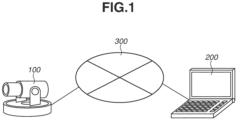
- Fig. 1 schematically illustrates a configuration of a system according to the present embodiment.
- the system according to the present embodiment includes an image processing apparatus 100 and a client apparatus 200.
- the image processing apparatus 100 also functions as an image capturing apparatus.
- the image processing apparatus 100 and the client apparatus 200 are communicably connected to each other via a network 300.
- the image processing apparatus 100 is assumed to be an apparatus (e.g., a network camera) capable of connecting to a network and communicating with another apparatus.
- the capability of connecting to a network is not essential, and the image processing apparatus 100 and the client apparatus 200 can be connected to each other directly with a High-Definition Multimedia Interface (HDMI ® ) cable or a serial digital interface (SDI) cable.
- a cut-out video image can be generated by acquiring a previously captured and stored image and then analyzing the acquired image.
- HDMI ® High-Definition Multimedia Interface
- SDI serial digital interface
- the client apparatus 200 transmits a distribution request command for requesting distribution of a video stream (or an image stream) and a setting command for setting various parameters, to the image processing apparatus 100 based on user's operations.
- the image processing apparatus 100 distributes the video stream to the client apparatus 200 based on the distribution request command, and stores various parameters based on the setting command.
- a configuration of the image processing apparatus 100 will be described below.
- the client apparatus 200 can be implemented by installing a predetermined program onto a computer such as a personal computer, a tablet terminal, or a smartphone.
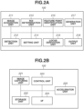
- Fig. 2A illustrates an example of functional blocks of the image processing apparatus 100.
- Fig. 2B illustrates an example of a hardware configuration of the image processing apparatus 100.
- the image processing apparatus 100 includes, as functional blocks, an image acquisition unit 211, a detection unit 212, a region-of-interest (ROI) determination unit 213, a setting unit 214, a feature point identification unit 215, a locus derivation unit 216, a generation unit 217, and an output unit 218.
- ROI region-of-interest
- FIG. 2A are implemented by a central processing unit (CPU) of the image processing apparatus 100 (the image capturing apparatus) executing a computer program stored in a read-only memory (ROM) of the image processing apparatus 100, which will be described below with reference to Fig. 2B .
- CPU central processing unit
- ROM read-only memory
- the image acquisition unit 211 acquires a moving image captured by an image capturing unit 221 (described below) or acquires a moving image from an external apparatus (not illustrated).
- the detection unit 212 performs object detection processing on each of a plurality of images included in the moving image acquired by the image acquisition unit 211 to detect objects therefrom.
- Examples of the objects to be detected by the detection unit 212 according to the present embodiment are players and a ball in the images.
- the detection unit 212 can use a method of generating a classifier in advance by learning the features of detection target objects using a machine learning method, and detecting the detection target objects from the images using the classifier.
- the detection unit 212 stores the images acquired by the image acquisition unit 211 and information about the objects detected from the images (position information and size information about the objects) in a storage unit 222.
- the ROI determination unit 213 calculates a region of interest (ROI) in each of the images based on the position information about the objects detected by the detection unit 212.
- the ROI determination unit 213 acquires information about a center position of the ROI in each of the images and stores the acquired information in the storage unit 222.
- the setting unit 214 sets a reference position for a cutting-out region. Details of the reference position setting will be described below. Information about the reference position set by the setting unit 214 is stored in the storage unit 222.
- the feature point identification unit 215 extracts feature points based on the information about the center position of the ROI acquired by the ROI determination unit 213 and the information about the reference position acquired by the setting unit 214.
- the extracted feature points are stored in the storage unit 222.
- the locus derivation unit 216 derives a locus (a cutting locus) indicating the movement of the position of the cutting-out region, based on the feature points acquired by the feature point identification unit 215. Information about the cutting locus derived by the locus derivation unit 216 is stored in the storage unit 222.
- the generation unit 217 performs cut-out processing on each of the plurality of images included in the moving image stored in the storage unit 222, based on the cutting locus derived by the locus derivation unit 216, and generates a series of cut-out images. Further, the generation unit 217 generates a moving image (hereinafter referred to as a cut-out moving image) including the series of cut-out images generated through the cut-out processing on each of the images included in the moving image.
- a cut-out moving image a moving image including the series of cut-out images generated through the cut-out processing on each of the images included in the moving image.
- the output unit 218 outputs the cut-out moving image generated by the generation unit 217 to an external apparatus via an interface (I/F) 224 (described below).
- I/F interface
- the image processing apparatus 100 includes, as hardware components, the image capturing unit 221, the storage unit 222, a control unit 223, the I/F 224, and an accelerator unit 225.
- the image capturing unit 221 uses an image sensor to receive light focused through a lens and convert the received light into charge to acquire a moving image.
- a complementary metal oxide semiconductor (CMOS) image sensor can be used as the image sensor.
- CMOS complementary metal oxide semiconductor
- CCD charge-coupled device
- the image capturing unit 221 is included in the hardware configuration is described as an example in the present embodiment, the image capturing unit 221 is not an essential hardware component, and a previously captured and stored moving image can be acquired via the network 300.
- the storage unit 222 includes both a ROM and a random-access memory (RAM) or includes one of a ROM and a RAM and stores programs for performing various operations and functions of the image processing apparatus 100. Further, the storage unit 222 can store data (such as commands and image data) and various parameters acquired from an external apparatus such as the client apparatus 200 via the I/F 224. For example, the storage unit 222 stores, for each of the images included in the moving image captured by the image capturing unit 221, information relating to camera settings in capturing the image, such as pan/tilt/zoom values, white balance information, and exposure information. The storage unit 222 can also store parameters relating to the captured moving image, including a frame rate of the moving image and a size (a resolution) of the moving image.
- the storage unit 222 can provide a work area to be used when the control unit 223 performs various types of processing. Furthermore, the storage unit 222 can function as a frame memory or a buffer memory. Besides a memory such as a ROM or a RAM, a storage medium such as a flexible disk, a hard disk, an optical disk, a magnetooptical disk, a compact disk (CD) ROM (CD-ROM), a CD recordable (CD-R), a magnetic tape, a non-volatile memory card, or a digital versatile disk (DVD) can be used as the storage unit 222.
- a memory such as a ROM or a RAM
- a storage medium such as a flexible disk, a hard disk, an optical disk, a magnetooptical disk, a compact disk (CD) ROM (CD-ROM), a CD recordable (CD-R), a magnetic tape, a non-volatile memory card, or a digital versatile disk (DVD) can be used as the storage unit 222.
- the control unit 223 includes a CPU or a micro-processing unit (MPU) and controls the entire image processing apparatus 100 by executing programs stored in the storage unit 222.
- MPU micro-processing unit
- control unit 223 can control the entire image processing apparatus 100 by collaborating with programs stored in the storage unit 222 and an operating system (OS).
- the control unit 223 can include a processor such as a digital signal processor (DSP) or an application-specific integrated circuit (ASIC).
- DSP digital signal processor
- ASIC application-specific integrated circuit
- the I/F 224 transmits and receives wired or wireless signals to communicate with the client apparatus 200 via the network 300.
- the accelerator unit 225 is a processing unit that includes a CPU, a graphics processing unit (GPU), a field-programmable gate array (FPGA), and a storage unit, and is added to a camera in order to mainly perform high-performance processing using deep learning.
- a CPU central processing unit
- GPU graphics processing unit
- FPGA field-programmable gate array
- the image processing apparatus 100 performs analysis processing such as the object detection processing
- the analysis processing can be performed by an accelerator unit added externally via a Universal Serial Bus (USB) or by a dedicated apparatus including a GPU or a FPGA.
- USB Universal Serial Bus
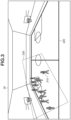
- Fig. 3 illustrates an image 30 captured by the image processing apparatus 100 so that the image 30 includes a plurality of players 310 playing basketball and an entire basketball court 320.
- Fig. 3 further illustrates a cutting-out region 330 that is determined by processing to be described below based on a result of detecting the players 310 and a ball included in the image 30.
- the position of the cutting-out region 330 may change between the images 30 of temporally previous and subsequent frames. This may be not only a reflection of the change due to the players 310 moving as the game develops but also a reflection of the change due to an error, such as erroneous detection or omission of detection, or a reflection of the change due to a movement, such as a dribble or a pass, based on which a camera is not supposed to be moved.
- the image processing apparatus 100 performs the following processing.
- the image processing apparatus 100 identifies feature points based on a locus corresponding to movement of the center position of the ROI determined for each image 30 included in the moving image. Then, a locus that smoothly connects the identified feature points is derived as a cutting locus, and the cutting-out region is moved along the cutting locus, whereby a smooth cut-out moving image is generated as a video image to be displayed.
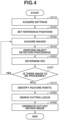
- Fig. 4 is a flowchart illustrating processing by the image processing apparatus 100 according to the present embodiment.
- the flowchart illustrated in Fig. 4 is implemented by, for example, the functional blocks of the image processing apparatus 100 that are illustrated in Fig. 2A and are implemented by the CPU of the image processing apparatus 100 executing a computer program stored in the ROM of the image processing apparatus 100.
- the processing to be described below is performed on a moving image recorded in advance (a moving image stored in the storage unit 222) as a processing target.
- a pan direction a horizontal direction
- the image acquisition unit 211 acquires settings relating to the moving image.
- the image acquisition unit 211 acquires parameters relating to the moving image from the storage unit 222.
- the parameters relating to the moving image include image capturing direction information about the image processing apparatus 100 (the image capturing apparatus), frame rate information, and image size (image resolution) information.
- image size information indicating 1920 ⁇ 1080 pixels and frame rate information indicating 30 fps are acquired as the parameters relating to the moving image.
- the setting unit 214 sets reference positions.
- the positions of right and left basketball goals and the position of the center of the court are set as the reference positions.
- Fig. 5 illustrates the set reference positions.
- a reference position 510 corresponding to the left side of the court a reference position 520 corresponding to the center of the court, and a reference position 530 corresponding to the right side of the court are set.
- the reference positions 510 to 530 set for the image 30 the reference position 510 located at one end and the reference position 530 located at the other end in the pan direction (the image horizontal direction) are referred to as range reference positions.
- the center position of the cutting-out region 330 can be located in a range between the range reference positions, i.e., between the reference position 510 and the reference position 530 in the pan direction (the image horizontal direction). Details thereof will be described below.
- the reference position setting can be performed manually by the user or can be set automatically by detecting a characteristic landmark of a target sport, such as a goal ring.
- the center can be set by deriving the reference position 520 as a center line between the reference positions 510 and 530 after setting the reference positions 510 and 530, instead of setting the center independently.
- the reference positions can be set differently for different use cases. For example, for face-to-face sports such as basketball, the reference positions are set at the center and sides of the court as illustrated in Fig. 5 . Similar examples apply to volleyball and tennis. For face-to-face sports played on large grounds, such as soccer and rugby, the reference positions can be set more finely.
- the image acquisition unit 211 acquires the images included in the processing target moving image.
- the processing target moving image is a moving image recorded in advance and is acquired from, for example, the storage unit 222 or an external apparatus. Further, each of the acquired images is an image with a bird's-eye view of an entire sport game, such as the image 30 illustrated in Fig. 3 , and a cut-out image is generated from such a bird's-eye view image.
- the bird's-eye view image can be an image generated by capturing an image of the entire basketball court 320 with a wide-angle camera as illustrated in the example of the basketball game in Fig.
- an image generated by converting a video image captured with a fisheye camera, or an image generated by combining video images from a plurality of cameras In the case of sports played on large grounds, such as soccer and rugby, it is difficult to cover an entire game within the angle of view of a single wide-angle camera, and thus a fisheye camera or a combined video image generated by combining images from a plurality of cameras is often used.
- step S440 the detection unit 212 performs the object detection processing on each of the images included in the processing target moving image and acquired in step S430, and detects the target objects therefrom.
- the scene of the basketball game illustrated in Fig. 3 is assumed, and the detection targets are the players 310 and a ball.
- object detection processing methods methods based on machine learning, especially based on deep learning, are known as methods that are highly accurate and achieve a higher speed capable of real-time processing.
- SSD is a method for detecting each object from an image including a plurality of objects.
- images each including a player and/or a ball are collected from a plurality of images to prepare learning data. More specifically, person regions and ball regions are extracted from the images, and a file describing coordinates of the center position of each of the extracted regions and the size thereof is generated. The learning data prepared in this manner is learned to configure a classifier for detecting human bodies and balls.
- An object such as a person or a ball is detected from an image using the classifier, and position information indicating the position of the region of the detected object and size information indicating the size of the region are acquired.
- the position information about the region of the detected object is indicated by X- and Y-coordinates of the center position of the region of the detected object, using the upper left of the image as origin coordinates.
- the size information about the region of the detected object is indicated by the number of pixels of the width of the region and the number of pixels of the height of the region.
- the ROI determination unit 213 determines the center position of the ROI based on the result of the object detection processing in step S440.
- different methods can be used for different use cases. For example, the ROI determination unit 213 determines, as the center position of the ROI, a center-of-gravity position based on the positions of one or a plurality of players and a ball that are detected from the image. In this case, the center-of-gravity position can be calculated using weighted averaging where a higher weight is assigned to the players or the ball.
- the ROI determination unit 213 can calculate the center-of-gravity position based on the positions of the one or plurality of players and the ball by using weighted averaging where a higher weight is assigned to the ball. Further, the weight can be changed based on how the game develops. More specifically, in a scene where a ball position is more important, such as a scene of a free throw in a basketball game or a scene of a goal kick in a soccer game, the weight to be assigned to the ball position in calculating the center-of-gravity position may be increased further. Alternatively, different weights can be set for different teams of players.
- a sponsor of one of the teams is to generate a cut-out video image including the players of the one of the teams at a center and a case where two patterns of cut-out moving images are generated by weighting the players of one of the teams for one pattern and weighting the players of the other team for the other pattern and then the user selects a desired cut-out moving image.
- a specific player can be weighted, and/or a specific play can be weighted.
- the ROI determination unit 213 determines a predetermined size (e.g., a size covering a half of the court) as the size of the ROI (corresponding to an enlargement ratio or the zoom ratio of a cut-out video image) in the present embodiment, the present embodiment is not limited thereto.
- step S460 the control unit 223 determines whether there is image data for which the ROI is to be determined. In a case where there is still an image for which the ROI is to be determined (YES in step S460), the processing returns to step S430 to perform the processing on the next image. In a case where there is no image for which the ROI is to be determined (NO in step S460), the processing proceeds to step S470.
- step S470 the feature point identification unit 215 extracts feature points for the cutting-out region, based on the center position of the ROI acquired for each image in step S450 and the reference positions set in step S420.
- Figs. 6A to 6E schematically illustrate the feature point extraction.
- Fig. 6A illustrates a locus 610 of the center position of the ROI in the pan direction in each image included in the processing target moving image.
- a horizontal axis indicates the number of frames of the images included in the processing target moving image, and ranges from 0 to 10000.
- each image 30 to be cut out has a size of 1920 ⁇ 1080 (pixels) (hereinafter referred to as px), and a range where the center position of the cutting-out region can move in the pan direction in digital panning/tilting/zooming (digital PTZ) is a range of 0 to 1920 (px) corresponding to the horizontal width of each image 30.
- the change in the center position of the ROI that is illustrated in Fig. 6A corresponds to a graph obtained by performing smoothing processing on a plot of the center position of the ROI acquired for each frame in step S450.
- Fig. 6B lines corresponding to the reference positions 510 to 530 are superimposed on the locus 610 of the movement of the center position of the ROI in Fig. 6A .
- the reference position 510 which is the range reference position corresponding to the left goal in the image 30, corresponds to a pan position of 600 (px) in the pan direction.
- the line corresponding to the reference position 510 is superimposed on the pan position of 600 (px).
- the reference position 520 corresponding to the center of the court in the image 30 corresponds to a pan position of 975 (px) in the pan direction.
- the line corresponding to the reference position 520 is superimposed on the pan position of 975 (px).
- the reference position 530 which is the range reference position corresponding to the right goal in the image 30, corresponds to a pan position of 1350 (px) in the pan direction.
- the line corresponding to the reference position 530 is superimposed on the pan position of 1350 (px).
- Fig. 6B further illustrates how feature points are identified.
- the feature point identification unit 215 extracts, as feature points, intersection points where the locus 610 of the center position of the ROI in each frame image intersects with the reference positions 510 to 530. Further, the feature point identification unit 215 adds an additional feature point to each of the start position (the position where the number of frames is 0) of the locus 610 and the end position (the position where the number of frames is 10000) of the locus 610.
- step S480 the locus derivation unit 216 derives a locus passing through the feature points identified in step S470, as a locus (a cutting locus) of the center position of the cutting-out region.
- a cutting locus 620 calculated in this manner is illustrated in Fig. 6C .
- the range where the center position of the cutting-out region can be located is the range between the range reference positions, i.e., between the reference position 510 and the reference position 530.
- the present embodiment is not limited thereto, and an additional feature point can also be used. A method for adding an additional feature point will be described now.
- the feature point identification unit 215 calculates a deviation between a line connecting adjacent two feature points among the feature points which are the intersection points where the locus 610 intersects with the reference positions 510 to 530, and the locus 610 between the two feature points.
- the feature point identification unit 215 derives a difference value in the pan position (px) between each position on the line connecting the two feature points and the corresponding position on the locus 610 between the two feature points and calculates, as a deviation, the maximum value among the difference values derived for the respective positions on the line. Then, the feature point identification unit 215 compares the calculated deviation between the line connecting the two feature points and the locus 610 between the two feature points and a threshold value. In a case where the deviation is greater than the threshold value, an additional feature point is added between the two feature points.
- the feature point identification unit 215 calculates a difference value in the pan position (px) between each position on a line connecting the feature points 630 and 640 and the corresponding position on the locus 610 between the feature points 630 and 640.
- the feature point identification unit 215 calculates, as a deviation, the maximum value among the difference values in the pan position (px) that are calculated for the respective positions on the line connecting the feature points 630 and 640.
- the feature point identification unit 215 compares the calculated deviation and a threshold value. In this case, the calculated deviation is assumed to be greater than the threshold value, and the feature point identification unit 215 adds the additional feature point 650. At this time, the additional feature point 650 is added to a position on the locus 610 that has the greatest difference value (the maximum value) among the difference values in the pan position (px) between the positions on the line connecting the feature points 630 and 640 and the corresponding positions on the locus 610 between the feature points 630 and 640. Further, another additional feature point 660 added using a similar method is illustrated in Fig. 6D .
- the locus derivation unit 216 derives a locus passing through the extracted feature points (including the additional feature points 650 and 660) as a locus (a cutting locus) of the center position of the cutting-out region.
- a cutting locus 670 derived in this manner is illustrated in Fig. 6E .
- a range of pan positions (px) to which an additional feature point can be added is limited to the range between the range reference positions, i.e., between the reference position 510 and the reference position 530.
- the range of pan positions (px) to which an additional feature point can be added is limited to the range from the reference position 510 at the left end in the pan direction (the horizontal direction) to the reference position 530 at the right end in the pan direction (the horizontal direction) in each image 30.
- an additional feature point is added to a position within the range from the pan position of 600 (px) to the pan position of 1350 (px).
- no additional feature points are to be added in a range of pan positions above the pan position (px) corresponding to the reference position 530 and in a range of pan positions below the pan position (px) corresponding to the reference position 510.
- a camera work i.e., the position of the cutting-out region
- the digital PTZ is fixed in a case where one of the teams continues to attack in the right or left part of the court as illustrated in Fig. 5 .
- step S480 the locus derivation unit 216 smoothly connects the feature points acquired in step S470 and illustrated in Fig. 6D and derives a cutting locus.
- the cutting locus 670 derived in this manner is illustrated in Fig. 6E .
- the range where the center position of the cutting-out region can be located is limited to the range between the range reference positions, i.e., between the reference position 510 and the reference position 530.
- the cutting locus 620 illustrated in Fig. 6C is calculated from the feature points illustrated in Fig. 6B
- the cutting locus 670 illustrated in Fig. 6E is derived from the feature points illustrated in Fig. 6D .
- a method for deriving a cutting locus will now be described in more detail. While there are various possible methods for deriving a cutting locus by connecting feature points, a method that achieves smoothness and high continuity is demanded.
- the locus derivation unit 216 derives a cutting locus from feature points using a piecewise cubic Hermite interpolation method.
- the piecewise cubic Hermite interpolation method is a method of dividing a domain into sub-domains and approximating each sub-domain using a polynomial of degree three or less, which enables interpolation smoothly connecting feature points without increasing the amount of calculation or memory.
- use of this method prevents, for example, overshoots deviating above or below the locus 610 and enables the smooth connection.
- no cutting loci that deviate above or below the locus 610 are to be generated, cases where the cutting-out region is located to cover the end of the court 320 in the pan direction as illustrated in the example of Fig. 3 are prevented. In other words, the cutting-out region is prevented from being located at a region not intended by the user (e.g., an end region outside the court).
- step S490 the generation unit 217 generates a cut-out image by cutting out the cutting-out region identified based on the cutting locus acquired in step S480 from each of the images of the frames included in the processing target moving image. Then, the generation unit 217 generates a cut-out moving image including the series of cut-out images respectively obtained from the images of the frames. In order to generate a cut-out image from an image, four apexes of the cutting-out region (e.g., the cutting-out region 330 illustrated in Fig. 5 ) in the image are to be calculated.
- the cutting-out region e.g., the cutting-out region 330 illustrated in Fig. 5
- the cutting-out region is identified so as to correspond to an image capturing region in a case where a camera installed at the same position as that of the image capturing apparatus having captured each image 30 captures an image of the center position (e.g., the pan position of 600 (px)) of the cutting-out region indicated by the cutting locus.
- a camera installed at the same position as that of the image capturing apparatus having captured each image 30 captures an image of the center position (e.g., the pan position of 600 (px)) of the cutting-out region indicated by the cutting locus.
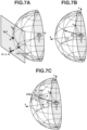
- FIG. 7A illustrates a relationship between each image (each image 30) included in the processing target moving image captured by the image capturing apparatus, and spherical coordinates where a position O of the image capturing apparatus is an origin point.
- the position O of the image capturing apparatus that captures moving images and the imaging range thereof are fixed, and there is no change in the positional relationship between the spherical coordinates illustrated in Fig. 7A and each of the images included in the moving image. Further, as illustrated in Fig.
- Fig. 7A the center position of each of the images included in the moving image is indicated by the letter R, and x- and z-axes respectively indicate a horizon direction of the image and a vertical direction of the image. Further, Fig. 7B defines the spherical coordinates (r, ⁇ , ⁇ ).
- the generation unit 217 identifies where the current processing target image is in the images of the frames included in the processing target moving image. For example, the processing target image is identified as the image of the four-thousandth frame. The generation unit 217 identifies the center position of the cutting-out region in the four-thousandth frame based on the derived cutting locus. In the case of the example of the cutting locus 670 illustrated in Fig. 6E , the generation unit 217 identifies 1350 (px) as the center position of the cutting-out region in the processing target image. Then, the generation unit 217 performs image transformation to transform the identified center position of the cutting-out region in the image in Fig.
- the generation unit 217 obtains the positions of the four apexes (F1, F2, F3, F4) on the spherical coordinates as specified by the following formula (1), with a horizontal angle of view of 2 ⁇ and a vertical angle of view of 2 ⁇ corresponding to the size of the cutting-out region.
- F 1 F 2 F 3 F 4 ( ⁇ c ⁇ ⁇ , ⁇ c + ⁇ ) ( ⁇ c ⁇ ⁇ , ⁇ c ⁇ ⁇ ) ( ⁇ c + ⁇ , ⁇ c ⁇ ⁇ ) ( ⁇ c + ⁇ , ⁇ c + ⁇ )
- the generation unit 217 acquires the four apexes of the cutting-out region by transforming the positions of the four apexes of the cutting-out region on the spherical coordinates to the coordinates on the processing target image illustrated in Fig. 7A again.
- the cutting-out region 330 in Fig. 3 is an example of the cutting-out region identified by the foregoing processing.
- the generation unit 217 generates a cut-out image by cutting out the cutting-out region identified on the processing target image and performing distortion correction processing, such as projective transformation, on the cut-out region.
- the above-described processing is performed on each of the images of the frames in the processing target moving image, and a cut-out image is generated from each of the images.
- the cut-out moving image including the series of cut-out images generated in step S490 is transmitted to an external apparatus by the output unit 218.
- the present embodiment is not limited thereto, and the cutting-out region can be changed on a tilt direction (an image vertical direction) in the image.
- the image processing apparatus 100 derives a locus of the position of the ROI in the tilt direction in each of the plurality of images included in the processing target moving image. Then, as described above with reference to Figs. 6A to 6E , the image processing apparatus 100 identifies feature points based on preset reference positions and the locus of the position of the ROI in the tilt direction, and derives a cutting locus connecting the feature points. Thereafter, the image processing apparatus 100 generates a series of cut-out images from the processing target moving image using the cutting locus.
- the image processing apparatus 100 determines the position of the ROI for each of a plurality of images included in a moving image and identifies feature points based on a locus of movement of the position of the ROI and reference positions. Then, the image processing apparatus 100 derives a cutting locus based on the identified feature points and generates a cut-out image from the cutting-out region identified based on the cutting locus in each of the plurality of images included in the moving image. Further, the image processing apparatus 100 acquires a cut-out moving image including the series of cut-out images respectively acquired from the plurality of images included in the moving image.
- a cut-out moving image that is unblurred despite a slight motion of a player or a dribble and follows a player or a ball without delay when the offense and defense switch is generated.
- the range of possible positions of the cutting-out region is limited using reference positions, and this prevents a region not intended by the user from being determined as the cutting-out region.
- a cutting locus suitable for a relatively long moving image is derived to generate a cut-out moving image.
- a case where the processing for deriving a cutting locus in steps S470 and S480 is divided by a time and performed will be described.
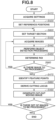
- FIG. 8 Processing by the image processing apparatus 100 according to the present embodiment will be described with reference to a flowchart illustrated in Fig. 8 .
- the flowchart illustrated in Fig. 8 is performed by, for example, the functional blocks of the image processing apparatus 100 that are illustrated in Fig. 2A and are implemented by the CPU of the image processing apparatus 100 executing a computer program stored in the ROM of the image processing apparatus 100. Steps other than steps S820, S860, S880, and S895 in the flowchart are similar to those according to the first embodiment described above with reference to Fig. 4 , and thus redundant descriptions thereof will be omitted.
- step S820 the setting unit 214 sets a target section (the number of seconds of a video image to be analyzed) corresponding to a range of the number of image frames to be analyzed for generating a cut-out moving image.
- a target section the number of seconds of a video image to be analyzed
- the target section is set to one minute corresponding to 1800 frames at 30 fps. At this time, the target section can be changed depending on the situation. While a case where the target section is constant is described below, the target section may be decreased in a case where the game develops speedily.
- step S860 the control unit 223 determines whether there is still an image frame for which the ROI is to be determined. In a case where the ROI determination is not completed for 1800 frames based on the target section set in step S820 (YES in step S860), the processing returns to step S430 to perform the processing on the next image frame. In a case where the ROI determination is completed for 1800 frames (NO in step S860), the processing proceeds to step S470.
- the locus derivation unit 216 derives a cutting locus using the feature points that are identified from the moving image of the current processing target section in step S470.
- the present embodiment is not limited thereto, and the locus derivation unit 216 can derive a cutting locus for the moving image of the current processing target section also using the feature points identified in the moving image of a previous target section immediately before the current processing target section. More specifically, the locus derivation unit 216 can derive a cutting locus based on the feature points identified based on the locus of the position of the ROI in 1800 frames corresponding to the current target section and the feature points close to the end of the previous target section (e.g., frames up to the fiftieth frame from the frame at the end). As described above, by adding the feature points identified in the moving image of the previous target section, a cut-out moving image that maintains continuity of cutting-out region positions even at boundaries of target sections is generated.
- step S895 the control unit 223 determines whether there is data from which a cut-out image is to be generated. In a case where there is still a moving image including unprocessed frame images and the cut-out processing on the next target section is to be performed (YES in step S895), the processing returns to step S820 to set the next target section. In a case where there is no moving image including unprocessed frame images and the cut-out processing on the next target section is not to be performed (NO in step S895), the processing illustrated in Fig. 8 ends.
- the image processing apparatus 100 divides an acquired moving image by a target section and continually generates cut-out moving images, whereby cut-out moving images are generated in a state close to real time.
- a program for implementing one or more functions according to the above-described embodiments is read and executed by one or more processors.
- the program can be supplied to a system or an apparatus including the one or more processors via a network or a storage medium.
- embodiments of the present invention can be implemented by a circuit (e.g., an ASIC) for implementing one or more functions according to the above-described embodiments.
- a circuit e.g., an ASIC
- the cutting-out regions can be determined more appropriately.
- Embodiment(s) of the present invention can also be realized by a computer of a system or apparatus that reads out and executes computer executable instructions (e.g., one or more programs) recorded on a storage medium (which may also be referred to more fully as a 'non-transitory computer-readable storage medium') to perform the functions of one or more of the above-described embodiment(s) and/or that includes one or more circuits (e.g., application specific integrated circuit (ASIC)) for performing the functions of one or more of the above-described embodiment(s), and by a method performed by the computer of the system or apparatus by, for example, reading out and executing the computer executable instructions from the storage medium to perform the functions of one or more of the above-described embodiment(s) and/or controlling the one or more circuits to perform the functions of one or more of the above-described embodiment(s).
- computer executable instructions e.g., one or more programs
- a storage medium which may also be referred to more fully as
- the computer may comprise one or more processors (e.g., central processing unit (CPU), micro processing unit (MPU)) and may include a network of separate computers or separate processors to read out and execute the computer executable instructions.
- the computer executable instructions may be provided to the computer, for example, from a network or the storage medium.
- the storage medium may include, for example, one or more of a hard disk, a random-access memory (RAM), a read only memory (ROM), a storage of distributed computing systems, an optical disk (such as a compact disc (CD), digital versatile disc (DVD), or Blu-ray Disc (BD) TM ), a flash memory device, a memory card, and the like.
Abstract
Description
- The present invention relates to an image processing technique.
- There is a technique for generating a cut-out image by cutting out a cutting-out region, which is a partial region to be cut out from an image, from the image. By gradually changing the position (or size) of the cutting-out region in the image, the imaging range of an image capturing apparatus can be changed virtually. Such processing for changing the position (or size) of the cutting-out region is referred to as digital panning/tilting/zooming (digital PTZ). Further, there is a technique for generating a cut-out image by determining a cutting-out region in an image based on positional information about one or a plurality of objects (e.g., persons) detected from the image and cutting out the determined cutting-out region from the image in the digital PTZ. With this technique, the positional change of the one or plurality of objects may cause a slight change in the position of the cutting-out region in each image included in a moving image. As a result of this, a moving image (a cut-out moving image) formed by the series of cut-out images may be difficult to view for a user and make the user feel strange. To address the issue,
Japanese Patent Application Laid-Open No. 2005-223487 - With the technique discussed in
Japanese Patent Application Laid-Open No. 2005-223487 - The present invention is directed to a technique capable of more appropriately determining cutting-out regions in a plurality of images included in a moving image in a case where cut-out images are generated from the cutting-out regions.
- According to a first aspect of the present invention, there is provided an image processing apparatus as specified in claims 1 to 7. According to a second aspect of the present invention, there is provided an image processing method as specified in claim 8. According to a third aspect of the present invention, there is provided a computer-executable program as specified in claim 9. According to a fourth aspect of the present invention, there is provided a non-transitory computer readable storage medium as specified in
claim 10. - Further features of the present invention will become apparent from the following description of embodiments with reference to the attached drawings.
-
-
Fig. 1 is a diagram illustrating an example of a system configuration. -
Figs. 2A is a diagram illustrating an example of functional blocks of an image processing apparatus.Fig. 2B is a diagram illustrating an example of a hardware configuration of the image processing apparatus. -
Fig. 3 is a diagram illustrating determination of a region of interest. -
Fig. 4 is a flowchart illustrating a procedure of processing for generating a cut-out moving image. -
Fig. 5 is a diagram illustrating a reference position. -
Figs. 6A, 6B, 6C, 6D, and 6E are diagrams illustrating a cutting locus. -
Figs. 7A, 7B, and 7C are diagrams illustrating processing for identifying a cutting-out region. -
Fig. 8 is a flowchart illustrating another processing for generating the cut-out moving image. - Embodiments of the present invention will be described in detail below with reference to the attached drawings. The below-described embodiments are not intended to limit the scope of the claimed invention. While a plurality of features in the embodiments is described below, not all the features are essential to the invention, and the features can be combined in any way. Further, components that are the same or similar are given the same reference numerals in the attached drawings, and redundant descriptions thereof will be omitted.
- While the capturing of images of sports scenes is described as an example in the following embodiments, the embodiments are not limited thereto and are also applicable to the capturing of images of various scenes of events, concerts, and lectures. Further, in the following embodiments, an image processing apparatus that functions as an image capturing apparatus (a network camera) capable of connecting to a network and communicating with another apparatus will be described. The embodiments, however, are not limited thereto and are also applicable to an image processing apparatus that functions as an image capturing apparatus incapable of connecting to a network. Further, while an image processing apparatus is described to have an image capturing function in the following embodiments, the embodiments are not limited thereto, and any apparatus other than an image processing apparatus can implement an image capturing function and the image processing apparatus can acquire captured images from the other apparatus. Further, the images acquired in this manner can be images generated by combining captured images from a plurality of images capturing apparatuses, for example, using stitching processing.
- An image processing apparatus according to a first embodiment acquires a moving image obtained by capturing images of sports scenes, and generates a cut-out image from a cutting-out region in each of the images included in the moving image by using a result of detecting players and a ball in the moving image. In the present embodiment, basketball scenes will be described as an example of a use case. Generally, in a basketball game, a scene where players gather at a right or left part of a court and attack while passing a ball and a scene where the offense and defense switch and players move across the court are repeated. Even in such a case, the present embodiment can achieve the movement of the position of the cutting-out region corresponding to the development of the game to follow the players and the ball without delay when the offense and defense switch, while suppressing slight variations in the position of the cutting-out region due to the influence of slight movements of the players.
-
Fig. 1 schematically illustrates a configuration of a system according to the present embodiment. The system according to the present embodiment includes animage processing apparatus 100 and aclient apparatus 200. Theimage processing apparatus 100 also functions as an image capturing apparatus. Theimage processing apparatus 100 and theclient apparatus 200 are communicably connected to each other via anetwork 300. In the present embodiment, theimage processing apparatus 100 is assumed to be an apparatus (e.g., a network camera) capable of connecting to a network and communicating with another apparatus. However, the capability of connecting to a network is not essential, and theimage processing apparatus 100 and theclient apparatus 200 can be connected to each other directly with a High-Definition Multimedia Interface (HDMI®) cable or a serial digital interface (SDI) cable. Further, a cut-out video image can be generated by acquiring a previously captured and stored image and then analyzing the acquired image. - The
client apparatus 200 transmits a distribution request command for requesting distribution of a video stream (or an image stream) and a setting command for setting various parameters, to theimage processing apparatus 100 based on user's operations. Theimage processing apparatus 100 distributes the video stream to theclient apparatus 200 based on the distribution request command, and stores various parameters based on the setting command. A configuration of theimage processing apparatus 100 will be described below. Theclient apparatus 200 can be implemented by installing a predetermined program onto a computer such as a personal computer, a tablet terminal, or a smartphone. - Next, the
image processing apparatus 100 will be described in further detail with reference toFigs. 2A and 2B. Fig. 2A illustrates an example of functional blocks of theimage processing apparatus 100.Fig. 2B illustrates an example of a hardware configuration of theimage processing apparatus 100. Referring toFig. 2A , theimage processing apparatus 100 includes, as functional blocks, animage acquisition unit 211, adetection unit 212, a region-of-interest (ROI)determination unit 213, asetting unit 214, a featurepoint identification unit 215, alocus derivation unit 216, ageneration unit 217, and anoutput unit 218. For example, the functional blocks illustrated inFig. 2A are implemented by a central processing unit (CPU) of the image processing apparatus 100 (the image capturing apparatus) executing a computer program stored in a read-only memory (ROM) of theimage processing apparatus 100, which will be described below with reference toFig. 2B . - The
image acquisition unit 211 acquires a moving image captured by an image capturing unit 221 (described below) or acquires a moving image from an external apparatus (not illustrated). - The
detection unit 212 performs object detection processing on each of a plurality of images included in the moving image acquired by theimage acquisition unit 211 to detect objects therefrom. Examples of the objects to be detected by thedetection unit 212 according to the present embodiment are players and a ball in the images. For example, thedetection unit 212 can use a method of generating a classifier in advance by learning the features of detection target objects using a machine learning method, and detecting the detection target objects from the images using the classifier. Thedetection unit 212 stores the images acquired by theimage acquisition unit 211 and information about the objects detected from the images (position information and size information about the objects) in astorage unit 222. - The
ROI determination unit 213 calculates a region of interest (ROI) in each of the images based on the position information about the objects detected by thedetection unit 212. TheROI determination unit 213 acquires information about a center position of the ROI in each of the images and stores the acquired information in thestorage unit 222. - The
setting unit 214 sets a reference position for a cutting-out region. Details of the reference position setting will be described below. Information about the reference position set by thesetting unit 214 is stored in thestorage unit 222. - The feature
point identification unit 215 extracts feature points based on the information about the center position of the ROI acquired by theROI determination unit 213 and the information about the reference position acquired by thesetting unit 214. The extracted feature points are stored in thestorage unit 222. - The
locus derivation unit 216 derives a locus (a cutting locus) indicating the movement of the position of the cutting-out region, based on the feature points acquired by the featurepoint identification unit 215. Information about the cutting locus derived by thelocus derivation unit 216 is stored in thestorage unit 222. - The
generation unit 217 performs cut-out processing on each of the plurality of images included in the moving image stored in thestorage unit 222, based on the cutting locus derived by thelocus derivation unit 216, and generates a series of cut-out images. Further, thegeneration unit 217 generates a moving image (hereinafter referred to as a cut-out moving image) including the series of cut-out images generated through the cut-out processing on each of the images included in the moving image. - The
output unit 218 outputs the cut-out moving image generated by thegeneration unit 217 to an external apparatus via an interface (I/F) 224 (described below). - Next, the example of the hardware configuration of the
image processing apparatus 100 will be described with reference toFig. 2B . As illustrated inFig. 2B , theimage processing apparatus 100 includes, as hardware components, theimage capturing unit 221, thestorage unit 222, acontrol unit 223, the I/F 224, and anaccelerator unit 225. - The
image capturing unit 221 uses an image sensor to receive light focused through a lens and convert the received light into charge to acquire a moving image. For example, a complementary metal oxide semiconductor (CMOS) image sensor can be used as the image sensor. Alternatively, a charge-coupled device (CCD) image sensor can be used as the image sensor. While a case where theimage capturing unit 221 is included in the hardware configuration is described as an example in the present embodiment, theimage capturing unit 221 is not an essential hardware component, and a previously captured and stored moving image can be acquired via thenetwork 300. - The
storage unit 222 includes both a ROM and a random-access memory (RAM) or includes one of a ROM and a RAM and stores programs for performing various operations and functions of theimage processing apparatus 100. Further, thestorage unit 222 can store data (such as commands and image data) and various parameters acquired from an external apparatus such as theclient apparatus 200 via the I/F 224. For example, thestorage unit 222 stores, for each of the images included in the moving image captured by theimage capturing unit 221, information relating to camera settings in capturing the image, such as pan/tilt/zoom values, white balance information, and exposure information. Thestorage unit 222 can also store parameters relating to the captured moving image, including a frame rate of the moving image and a size (a resolution) of the moving image. - Further, the
storage unit 222 can provide a work area to be used when thecontrol unit 223 performs various types of processing. Furthermore, thestorage unit 222 can function as a frame memory or a buffer memory. Besides a memory such as a ROM or a RAM, a storage medium such as a flexible disk, a hard disk, an optical disk, a magnetooptical disk, a compact disk (CD) ROM (CD-ROM), a CD recordable (CD-R), a magnetic tape, a non-volatile memory card, or a digital versatile disk (DVD) can be used as thestorage unit 222. - The
control unit 223 includes a CPU or a micro-processing unit (MPU) and controls the entireimage processing apparatus 100 by executing programs stored in thestorage unit 222. - Alternatively, the
control unit 223 can control the entireimage processing apparatus 100 by collaborating with programs stored in thestorage unit 222 and an operating system (OS). Thecontrol unit 223 can include a processor such as a digital signal processor (DSP) or an application-specific integrated circuit (ASIC). - The I/
F 224 transmits and receives wired or wireless signals to communicate with theclient apparatus 200 via thenetwork 300. - The
accelerator unit 225 is a processing unit that includes a CPU, a graphics processing unit (GPU), a field-programmable gate array (FPGA), and a storage unit, and is added to a camera in order to mainly perform high-performance processing using deep learning. - Next, processing by the
image processing apparatus 100 according to the present embodiment will be described with reference toFigs. 3 and4 . While a case where theimage processing apparatus 100 performs analysis processing such as the object detection processing is described in the present embodiment, the analysis processing can be performed by an accelerator unit added externally via a Universal Serial Bus (USB) or by a dedicated apparatus including a GPU or a FPGA. - In the present embodiment, a use case where a sport competition is set as a target as illustrated in
Fig. 3 is assumed.Fig. 3 illustrates animage 30 captured by theimage processing apparatus 100 so that theimage 30 includes a plurality ofplayers 310 playing basketball and anentire basketball court 320.Fig. 3 further illustrates a cutting-outregion 330 that is determined by processing to be described below based on a result of detecting theplayers 310 and a ball included in theimage 30. - In a case where the object detection processing is performed on each
image 30 included in a moving image to detect theplayers 310 and a ball therefrom and the cutting-outregion 330 is determined based on the result of the object detection processing, the position of the cutting-outregion 330 may change between theimages 30 of temporally previous and subsequent frames. This may be not only a reflection of the change due to theplayers 310 moving as the game develops but also a reflection of the change due to an error, such as erroneous detection or omission of detection, or a reflection of the change due to a movement, such as a dribble or a pass, based on which a camera is not supposed to be moved. In order to reduce such fluctuations in the position of the cutting-out region to be cut out, theimage processing apparatus 100 according to the present embodiment performs the following processing. Theimage processing apparatus 100 identifies feature points based on a locus corresponding to movement of the center position of the ROI determined for eachimage 30 included in the moving image. Then, a locus that smoothly connects the identified feature points is derived as a cutting locus, and the cutting-out region is moved along the cutting locus, whereby a smooth cut-out moving image is generated as a video image to be displayed. -
Fig. 4 is a flowchart illustrating processing by theimage processing apparatus 100 according to the present embodiment. The flowchart illustrated inFig. 4 is implemented by, for example, the functional blocks of theimage processing apparatus 100 that are illustrated inFig. 2A and are implemented by the CPU of theimage processing apparatus 100 executing a computer program stored in the ROM of theimage processing apparatus 100. In the present embodiment, the processing to be described below is performed on a moving image recorded in advance (a moving image stored in the storage unit 222) as a processing target. A case where the position of the cutting-out region is changed in a pan direction (a horizontal direction) on an image will be described as an example in the present embodiment. - In step S410, the
image acquisition unit 211 acquires settings relating to the moving image. For example, theimage acquisition unit 211 acquires parameters relating to the moving image from thestorage unit 222. The parameters relating to the moving image include image capturing direction information about the image processing apparatus 100 (the image capturing apparatus), frame rate information, and image size (image resolution) information. In the present embodiment, for example, image size information indicating 1920 × 1080 pixels and frame rate information indicating 30 fps are acquired as the parameters relating to the moving image. - Next, in step S420, the
setting unit 214 sets reference positions. In the present embodiment, the positions of right and left basketball goals and the position of the center of the court are set as the reference positions.Fig. 5 illustrates the set reference positions. As illustrated inFig. 5 , areference position 510 corresponding to the left side of the court, areference position 520 corresponding to the center of the court, and areference position 530 corresponding to the right side of the court are set. Among thereference positions 510 to 530 set for theimage 30, thereference position 510 located at one end and thereference position 530 located at the other end in the pan direction (the image horizontal direction) are referred to as range reference positions. The center position of the cutting-outregion 330 can be located in a range between the range reference positions, i.e., between thereference position 510 and thereference position 530 in the pan direction (the image horizontal direction). Details thereof will be described below. The reference position setting can be performed manually by the user or can be set automatically by detecting a characteristic landmark of a target sport, such as a goal ring. - Further, like the
reference position 520 inFig. 5 , the center can be set by deriving thereference position 520 as a center line between the reference positions 510 and 530 after setting the reference positions 510 and 530, instead of setting the center independently. - The reference positions can be set differently for different use cases. For example, for face-to-face sports such as basketball, the reference positions are set at the center and sides of the court as illustrated in
Fig. 5 . Similar examples apply to volleyball and tennis. For face-to-face sports played on large grounds, such as soccer and rugby, the reference positions can be set more finely. - In step S430, the
image acquisition unit 211 acquires the images included in the processing target moving image. The processing target moving image is a moving image recorded in advance and is acquired from, for example, thestorage unit 222 or an external apparatus. Further, each of the acquired images is an image with a bird's-eye view of an entire sport game, such as theimage 30 illustrated inFig. 3 , and a cut-out image is generated from such a bird's-eye view image. The bird's-eye view image can be an image generated by capturing an image of theentire basketball court 320 with a wide-angle camera as illustrated in the example of the basketball game inFig. 3 , an image generated by converting a video image captured with a fisheye camera, or an image generated by combining video images from a plurality of cameras. In the case of sports played on large grounds, such as soccer and rugby, it is difficult to cover an entire game within the angle of view of a single wide-angle camera, and thus a fisheye camera or a combined video image generated by combining images from a plurality of cameras is often used. - In step S440, the
detection unit 212 performs the object detection processing on each of the images included in the processing target moving image and acquired in step S430, and detects the target objects therefrom. In the present embodiment, the scene of the basketball game illustrated inFig. 3 is assumed, and the detection targets are theplayers 310 and a ball. Among object detection processing methods, methods based on machine learning, especially based on deep learning, are known as methods that are highly accurate and achieve a higher speed capable of real-time processing. - Specific methods thereof are You Only Look Once (YOLO) and Single Shot MultiBox Detector (SSD), and a case where SSD is used will be described now. SSD is a method for detecting each object from an image including a plurality of objects. In order to configure a classifier for detecting players and a ball using SSD, images each including a player and/or a ball are collected from a plurality of images to prepare learning data. More specifically, person regions and ball regions are extracted from the images, and a file describing coordinates of the center position of each of the extracted regions and the size thereof is generated. The learning data prepared in this manner is learned to configure a classifier for detecting human bodies and balls. An object such as a person or a ball is detected from an image using the classifier, and position information indicating the position of the region of the detected object and size information indicating the size of the region are acquired. The position information about the region of the detected object is indicated by X- and Y-coordinates of the center position of the region of the detected object, using the upper left of the image as origin coordinates. Further, the size information about the region of the detected object is indicated by the number of pixels of the width of the region and the number of pixels of the height of the region.
- In step S450, the
ROI determination unit 213 determines the center position of the ROI based on the result of the object detection processing in step S440. To determine the ROI, different methods can be used for different use cases. For example, theROI determination unit 213 determines, as the center position of the ROI, a center-of-gravity position based on the positions of one or a plurality of players and a ball that are detected from the image. In this case, the center-of-gravity position can be calculated using weighted averaging where a higher weight is assigned to the players or the ball. For example, theROI determination unit 213 can calculate the center-of-gravity position based on the positions of the one or plurality of players and the ball by using weighted averaging where a higher weight is assigned to the ball. Further, the weight can be changed based on how the game develops. More specifically, in a scene where a ball position is more important, such as a scene of a free throw in a basketball game or a scene of a goal kick in a soccer game, the weight to be assigned to the ball position in calculating the center-of-gravity position may be increased further. Alternatively, different weights can be set for different teams of players. There may be a case where a sponsor of one of the teams is to generate a cut-out video image including the players of the one of the teams at a center and a case where two patterns of cut-out moving images are generated by weighting the players of one of the teams for one pattern and weighting the players of the other team for the other pattern and then the user selects a desired cut-out moving image. Furthermore, a specific player can be weighted, and/or a specific play can be weighted. - As described above, there are various methods for determining the ROI, and the user may select a desired determination method. Further, a plurality of patterns of cut-out moving images can be generated using a respective plurality of determination methods. Further, while the
ROI determination unit 213 determines a predetermined size (e.g., a size covering a half of the court) as the size of the ROI (corresponding to an enlargement ratio or the zoom ratio of a cut-out video image) in the present embodiment, the present embodiment is not limited thereto. - In step S460, the
control unit 223 determines whether there is image data for which the ROI is to be determined. In a case where there is still an image for which the ROI is to be determined (YES in step S460), the processing returns to step S430 to perform the processing on the next image. In a case where there is no image for which the ROI is to be determined (NO in step S460), the processing proceeds to step S470. - In step S470, the feature
point identification unit 215 extracts feature points for the cutting-out region, based on the center position of the ROI acquired for each image in step S450 and the reference positions set in step S420. -
Figs. 6A to 6E schematically illustrate the feature point extraction.Fig. 6A illustrates alocus 610 of the center position of the ROI in the pan direction in each image included in the processing target moving image. A horizontal axis indicates the number of frames of the images included in the processing target moving image, and ranges from 0 to 10000. Further, as illustrated inFig. 3 , eachimage 30 to be cut out has a size of 1920 × 1080 (pixels) (hereinafter referred to as px), and a range where the center position of the cutting-out region can move in the pan direction in digital panning/tilting/zooming (digital PTZ) is a range of 0 to 1920 (px) corresponding to the horizontal width of eachimage 30. The change in the center position of the ROI that is illustrated inFig. 6A corresponds to a graph obtained by performing smoothing processing on a plot of the center position of the ROI acquired for each frame in step S450. - In
Fig. 6B , lines corresponding to thereference positions 510 to 530 are superimposed on thelocus 610 of the movement of the center position of the ROI inFig. 6A . InFig. 6B , thereference position 510, which is the range reference position corresponding to the left goal in theimage 30, corresponds to a pan position of 600 (px) in the pan direction. Thus, inFig. 6B , the line corresponding to thereference position 510 is superimposed on the pan position of 600 (px). Further, thereference position 520 corresponding to the center of the court in theimage 30 corresponds to a pan position of 975 (px) in the pan direction. - Thus, in
Fig. 6B , the line corresponding to thereference position 520 is superimposed on the pan position of 975 (px). Further, thereference position 530, which is the range reference position corresponding to the right goal in theimage 30, corresponds to a pan position of 1350 (px) in the pan direction. Thus, inFig. 6B , the line corresponding to thereference position 530 is superimposed on the pan position of 1350 (px). -
Fig. 6B further illustrates how feature points are identified. The featurepoint identification unit 215 according to the present embodiment extracts, as feature points, intersection points where thelocus 610 of the center position of the ROI in each frame image intersects with thereference positions 510 to 530. Further, the featurepoint identification unit 215 adds an additional feature point to each of the start position (the position where the number of frames is 0) of thelocus 610 and the end position (the position where the number of frames is 10000) of thelocus 610. - Next, in step S480, the
locus derivation unit 216 derives a locus passing through the feature points identified in step S470, as a locus (a cutting locus) of the center position of the cutting-out region. A cuttinglocus 620 calculated in this manner is illustrated inFig. 6C . As illustrated inFig. 6C , the range where the center position of the cutting-out region can be located is the range between the range reference positions, i.e., between thereference position 510 and thereference position 530. - While the intersection points where the
locus 610 of the center position of the ROI in each frame image intersects with thereference positions 510 to 530 are used as the feature points in deriving the cutting locus in the present embodiment, the present embodiment is not limited thereto, and an additional feature point can also be used. A method for adding an additional feature point will be described now. In this case, the featurepoint identification unit 215 calculates a deviation between a line connecting adjacent two feature points among the feature points which are the intersection points where thelocus 610 intersects with thereference positions 510 to 530, and thelocus 610 between the two feature points. More specifically, the featurepoint identification unit 215 derives a difference value in the pan position (px) between each position on the line connecting the two feature points and the corresponding position on thelocus 610 between the two feature points and calculates, as a deviation, the maximum value among the difference values derived for the respective positions on the line. Then, the featurepoint identification unit 215 compares the calculated deviation between the line connecting the two feature points and thelocus 610 between the two feature points and a threshold value. In a case where the deviation is greater than the threshold value, an additional feature point is added between the two feature points. A case where anadditional feature point 650 is derived from adjacent feature points 630 and 640 among the feature points which are the intersection points where thelocus 610 of the center position of the ROI intersects with thereference positions 510 to 530 will be described with reference toFig. 6D . The featurepoint identification unit 215 calculates a difference value in the pan position (px) between each position on a line connecting the feature points 630 and 640 and the corresponding position on thelocus 610 between the feature points 630 and 640. The featurepoint identification unit 215 calculates, as a deviation, the maximum value among the difference values in the pan position (px) that are calculated for the respective positions on the line connecting the feature points 630 and 640. Then, the featurepoint identification unit 215 compares the calculated deviation and a threshold value. In this case, the calculated deviation is assumed to be greater than the threshold value, and the featurepoint identification unit 215 adds theadditional feature point 650. At this time, theadditional feature point 650 is added to a position on thelocus 610 that has the greatest difference value (the maximum value) among the difference values in the pan position (px) between the positions on the line connecting the feature points 630 and 640 and the corresponding positions on thelocus 610 between the feature points 630 and 640. Further, anotheradditional feature point 660 added using a similar method is illustrated inFig. 6D . After the additional feature points 650 and 660 are added, thelocus derivation unit 216 derives a locus passing through the extracted feature points (including the additional feature points 650 and 660) as a locus (a cutting locus) of the center position of the cutting-out region. A cuttinglocus 670 derived in this manner is illustrated inFig. 6E . - A range of pan positions (px) to which an additional feature point can be added is limited to the range between the range reference positions, i.e., between the
reference position 510 and thereference position 530. In other words, the range of pan positions (px) to which an additional feature point can be added is limited to the range from thereference position 510 at the left end in the pan direction (the horizontal direction) to thereference position 530 at the right end in the pan direction (the horizontal direction) in eachimage 30. In the example ofFig. 6B , an additional feature point is added to a position within the range from the pan position of 600 (px) to the pan position of 1350 (px). More specifically, no additional feature points are to be added in a range of pan positions above the pan position (px) corresponding to thereference position 530 and in a range of pan positions below the pan position (px) corresponding to thereference position 510. This limits the center position of the cutting-out region strictly within the range from thereference position 510 to thereference position 530. With such limitation, a camera work (i.e., the position of the cutting-out region) in the digital PTZ is fixed in a case where one of the teams continues to attack in the right or left part of the court as illustrated inFig. 5 . - Referring back to
Fig. 4 , in step S480, thelocus derivation unit 216 smoothly connects the feature points acquired in step S470 and illustrated inFig. 6D and derives a cutting locus. The cuttinglocus 670 derived in this manner is illustrated inFig. 6E . At this time, as described above, the range where the center position of the cutting-out region can be located is limited to the range between the range reference positions, i.e., between thereference position 510 and thereference position 530. - As described above, the cutting
locus 620 illustrated inFig. 6C is calculated from the feature points illustrated inFig. 6B , and thecutting locus 670 illustrated inFig. 6E is derived from the feature points illustrated inFig. 6D . A method for deriving a cutting locus will now be described in more detail. While there are various possible methods for deriving a cutting locus by connecting feature points, a method that achieves smoothness and high continuity is demanded. For example, thelocus derivation unit 216 derives a cutting locus from feature points using a piecewise cubic Hermite interpolation method. The piecewise cubic Hermite interpolation method is a method of dividing a domain into sub-domains and approximating each sub-domain using a polynomial of degree three or less, which enables interpolation smoothly connecting feature points without increasing the amount of calculation or memory. Thus, use of this method prevents, for example, overshoots deviating above or below thelocus 610 and enables the smooth connection. Further, since no cutting loci that deviate above or below thelocus 610 are to be generated, cases where the cutting-out region is located to cover the end of thecourt 320 in the pan direction as illustrated in the example ofFig. 3 are prevented. In other words, the cutting-out region is prevented from being located at a region not intended by the user (e.g., an end region outside the court). - In step S490, the
generation unit 217 generates a cut-out image by cutting out the cutting-out region identified based on the cutting locus acquired in step S480 from each of the images of the frames included in the processing target moving image. Then, thegeneration unit 217 generates a cut-out moving image including the series of cut-out images respectively obtained from the images of the frames. In order to generate a cut-out image from an image, four apexes of the cutting-out region (e.g., the cutting-outregion 330 illustrated inFig. 5 ) in the image are to be calculated. In the present embodiment, the cutting-out region is identified so as to correspond to an image capturing region in a case where a camera installed at the same position as that of the image capturing apparatus having captured eachimage 30 captures an image of the center position (e.g., the pan position of 600 (px)) of the cutting-out region indicated by the cutting locus. - A method for calculating the four apexes of the cutting-out region from each of the images of the frames included in the processing target moving image will be described with reference to
Figs. 7A to 7C. Fig. 7A illustrates a relationship between each image (each image 30) included in the processing target moving image captured by the image capturing apparatus, and spherical coordinates where a position O of the image capturing apparatus is an origin point. In the present embodiment, the position O of the image capturing apparatus that captures moving images and the imaging range thereof are fixed, and there is no change in the positional relationship between the spherical coordinates illustrated inFig. 7A and each of the images included in the moving image. Further, as illustrated inFig. 7A , the center position of each of the images included in the moving image is indicated by the letter R, and x- and z-axes respectively indicate a horizon direction of the image and a vertical direction of the image. Further,Fig. 7B defines the spherical coordinates (r, θ, ϕ). - The
generation unit 217 identifies where the current processing target image is in the images of the frames included in the processing target moving image. For example, the processing target image is identified as the image of the four-thousandth frame. Thegeneration unit 217 identifies the center position of the cutting-out region in the four-thousandth frame based on the derived cutting locus. In the case of the example of the cuttinglocus 670 illustrated inFig. 6E , thegeneration unit 217 identifies 1350 (px) as the center position of the cutting-out region in the processing target image. Then, thegeneration unit 217 performs image transformation to transform the identified center position of the cutting-out region in the image inFig. 7A into a point U (θc, ϕc) on the spherical coordinates. The point U at this time is illustrated inFig. 7C . Using the point U as the center, thegeneration unit 217 obtains the positions of the four apexes (F1, F2, F3, F4) on the spherical coordinates as specified by the following formula (1), with a horizontal angle of view of 2Δθ and a vertical angle of view of 2Δϕ corresponding to the size of the cutting-out region.
- Then, the
generation unit 217 acquires the four apexes of the cutting-out region by transforming the positions of the four apexes of the cutting-out region on the spherical coordinates to the coordinates on the processing target image illustrated inFig. 7A again. The cutting-outregion 330 inFig. 3 is an example of the cutting-out region identified by the foregoing processing. Then, thegeneration unit 217 generates a cut-out image by cutting out the cutting-out region identified on the processing target image and performing distortion correction processing, such as projective transformation, on the cut-out region. The above-described processing is performed on each of the images of the frames in the processing target moving image, and a cut-out image is generated from each of the images. - Then, the cut-out moving image including the series of cut-out images generated in step S490 is transmitted to an external apparatus by the
output unit 218. - While the case where the center position of the cutting-out region is changed on the pan direction (the image horizontal direction) in the image has been described above, the present embodiment is not limited thereto, and the cutting-out region can be changed on a tilt direction (an image vertical direction) in the image. In this case, the
image processing apparatus 100 derives a locus of the position of the ROI in the tilt direction in each of the plurality of images included in the processing target moving image. Then, as described above with reference toFigs. 6A to 6E , theimage processing apparatus 100 identifies feature points based on preset reference positions and the locus of the position of the ROI in the tilt direction, and derives a cutting locus connecting the feature points. Thereafter, theimage processing apparatus 100 generates a series of cut-out images from the processing target moving image using the cutting locus. - As described above, the
image processing apparatus 100 according to the present embodiment determines the position of the ROI for each of a plurality of images included in a moving image and identifies feature points based on a locus of movement of the position of the ROI and reference positions. Then, theimage processing apparatus 100 derives a cutting locus based on the identified feature points and generates a cut-out image from the cutting-out region identified based on the cutting locus in each of the plurality of images included in the moving image. Further, theimage processing apparatus 100 acquires a cut-out moving image including the series of cut-out images respectively acquired from the plurality of images included in the moving image. - By performing the foregoing processing, for example, a cut-out moving image that is unblurred despite a slight motion of a player or a dribble and follows a player or a ball without delay when the offense and defense switch is generated. Further, the range of possible positions of the cutting-out region is limited using reference positions, and this prevents a region not intended by the user from being determined as the cutting-out region.
- Next, a second embodiment will be described. Redundant descriptions of parts similar to those in the first embodiment will be omitted. In the above-described method according to the first embodiment, a cutting locus suitable for a relatively long moving image is derived to generate a cut-out moving image. In the present embodiment, a case where the processing for deriving a cutting locus in steps S470 and S480 is divided by a time and performed will be described.
- Processing by the
image processing apparatus 100 according to the present embodiment will be described with reference to a flowchart illustrated inFig. 8 . The flowchart illustrated inFig. 8 is performed by, for example, the functional blocks of theimage processing apparatus 100 that are illustrated inFig. 2A and are implemented by the CPU of theimage processing apparatus 100 executing a computer program stored in the ROM of theimage processing apparatus 100. Steps other than steps S820, S860, S880, and S895 in the flowchart are similar to those according to the first embodiment described above with reference toFig. 4 , and thus redundant descriptions thereof will be omitted. - In step S820, the
setting unit 214 sets a target section (the number of seconds of a video image to be analyzed) corresponding to a range of the number of image frames to be analyzed for generating a cut-out moving image. The longer the target section, the more the entire flow is considered, so that a smooth camera work is achieved in the digital PTZ. However, this delays the generating of a cut-out moving image by the time length, and it takes time for the user to view a video image. For example, in basketball, there are a 24-second rule (which states that, during an offense, an attempt to take a shot has to be made within 24 seconds) and a 14-second rule (which states that, in the case of an offensive rebound, an attempt to take the next shot has to be made within 14 seconds). These rules are intended to encourage fast-paced games. Considering the rules, players are less likely to stay at one side of the court for one minute or longer. Thus, the target section is set to one minute corresponding to 1800 frames at 30 fps. At this time, the target section can be changed depending on the situation. While a case where the target section is constant is described below, the target section may be decreased in a case where the game develops speedily. - In step S860, the
control unit 223 determines whether there is still an image frame for which the ROI is to be determined. In a case where the ROI determination is not completed for 1800 frames based on the target section set in step S820 (YES in step S860), the processing returns to step S430 to perform the processing on the next image frame. In a case where the ROI determination is completed for 1800 frames (NO in step S860), the processing proceeds to step S470. - In step S880, the
locus derivation unit 216 derives a cutting locus using the feature points that are identified from the moving image of the current processing target section in step S470. The present embodiment is not limited thereto, and thelocus derivation unit 216 can derive a cutting locus for the moving image of the current processing target section also using the feature points identified in the moving image of a previous target section immediately before the current processing target section. More specifically, thelocus derivation unit 216 can derive a cutting locus based on the feature points identified based on the locus of the position of the ROI in 1800 frames corresponding to the current target section and the feature points close to the end of the previous target section (e.g., frames up to the fiftieth frame from the frame at the end). As described above, by adding the feature points identified in the moving image of the previous target section, a cut-out moving image that maintains continuity of cutting-out region positions even at boundaries of target sections is generated. - In step S895, the
control unit 223 determines whether there is data from which a cut-out image is to be generated. In a case where there is still a moving image including unprocessed frame images and the cut-out processing on the next target section is to be performed (YES in step S895), the processing returns to step S820 to set the next target section. In a case where there is no moving image including unprocessed frame images and the cut-out processing on the next target section is not to be performed (NO in step S895), the processing illustrated inFig. 8 ends. - As described above, the
image processing apparatus 100 according to the present embodiment divides an acquired moving image by a target section and continually generates cut-out moving images, whereby cut-out moving images are generated in a state close to real time. - Further, the embodiments of the present invention can be implemented by the following processing. A program for implementing one or more functions according to the above-described embodiments is read and executed by one or more processors. The program can be supplied to a system or an apparatus including the one or more processors via a network or a storage medium.
- Further, the embodiments of the present invention can be implemented by a circuit (e.g., an ASIC) for implementing one or more functions according to the above-described embodiments.
- Further, the present invention is not limited to the embodiments described above, and various changes can be made within the spirit of the present invention. For example, combinations of the embodiments are also encompassed within the disclosure of the present specification.
- According to the above-described embodiments, in a case where cut-out images are generated from cutting-out regions in a plurality of images included in a moving image, the cutting-out regions can be determined more appropriately.
- Embodiment(s) of the present invention can also be realized by a computer of a system or apparatus that reads out and executes computer executable instructions (e.g., one or more programs) recorded on a storage medium (which may also be referred to more fully as a 'non-transitory computer-readable storage medium') to perform the functions of one or more of the above-described embodiment(s) and/or that includes one or more circuits (e.g., application specific integrated circuit (ASIC)) for performing the functions of one or more of the above-described embodiment(s), and by a method performed by the computer of the system or apparatus by, for example, reading out and executing the computer executable instructions from the storage medium to perform the functions of one or more of the above-described embodiment(s) and/or controlling the one or more circuits to perform the functions of one or more of the above-described embodiment(s). The computer may comprise one or more processors (e.g., central processing unit (CPU), micro processing unit (MPU)) and may include a network of separate computers or separate processors to read out and execute the computer executable instructions. The computer executable instructions may be provided to the computer, for example, from a network or the storage medium. The storage medium may include, for example, one or more of a hard disk, a random-access memory (RAM), a read only memory (ROM), a storage of distributed computing systems, an optical disk (such as a compact disc (CD), digital versatile disc (DVD), or Blu-ray Disc (BD)™), a flash memory device, a memory card, and the like.
- While the present invention has been described with reference to embodiments, it is to be understood that the invention is not limited to the disclosed embodiments but is defined by the scope of the following claims.
Claims (10)
- An image processing apparatus (100) comprising:acquisition means (211) configured to acquire a moving image to be processed;detection means (212) configured to detect an object from each of a plurality of images included in the moving image;determination means (213) configured to determine a position of a region of interest in each of the plurality of images included in the moving image, based on a result of the detection by the detection means (212);derivation means (216) configured to derive a cutting locus for the moving image based on a locus corresponding to movement of the position of the region of interest determined by the determination means and a reference position (510, 520, 530) for a cutting-out region (330), the cutting locus being a locus corresponding to movement of a position of the cutting-out region; andgeneration means (217) configured to generate a cut-out image from the cutting-out region identified based on the cutting locus in each of the plurality of images included in the moving image.
- The image processing apparatus according to claim 1, further comprising identification means (215) configured to identify a feature point to be used to derive the cutting locus for the moving image, based on the locus corresponding to the movement of the position of the region of interest determined by the determination means (213) and the reference position,
wherein the derivation means (216) is configured to derive the cutting locus based on the feature point identified by the identification means (215). - The image processing apparatus according to claim 2, wherein the identification means (215) is configured to identify the feature point based on an intersection point where the locus corresponding to the movement of the region of interest intersects with the reference position.
- The image processing apparatus according to claim 3,wherein the identification means (215) is configured to identify an additional feature point using the feature point identified based on the intersection point where the locus corresponding to the movement of the region of interest intersects with the reference position, andwherein the derivation means (216) is configured to derive the cutting locus based on the feature point and the additional feature point.
- The image processing apparatus according to any one of the preceding claims, wherein the reference position is set based on a user's operation.
- The image processing apparatus according to any one of claims 1 to 4, wherein the reference position is set based on a position of a specific object detected from each of the plurality of images by the detection means.
- The image processing apparatus according to any one of the preceding claims, wherein the moving image acquired by the acquisition means (211) is a moving image recorded in advance.
- An image processing method comprising:acquiring a moving image to be processed;detecting an object from each of a plurality of images included in the moving image;determining a position of a region of interest in each of the plurality of images included in the moving image, based on a result of the detecting;deriving a cutting locus for the moving image based on a locus corresponding to movement of the determined position of the region of interest and a reference position (510, 520, 530) for a cutting-out region (330), the cutting locus being a locus corresponding to movement of a position of the cutting-out region; andgenerating a cut-out image from the cutting-out region identified based on the cutting locus in each of the plurality of images included in the moving image.
- A computer-executable program for causing a computer to perform an image processing method according to claim 8.
- A non-transitory computer readable storage medium storing a computer-executable program according to claim 9.
Applications Claiming Priority (1)
| Application Number | Priority Date | Filing Date | Title |
|---|---|---|---|
| JP2022012430A JP2023110780A (en) | 2022-01-28 | 2022-01-28 | Image processing device, image processing method, and program |
Publications (1)
| Publication Number | Publication Date |
|---|---|
| EP4220556A1 true EP4220556A1 (en) | 2023-08-02 |
Family
ID=84943157
Family Applications (1)
| Application Number | Title | Priority Date | Filing Date |
|---|---|---|---|
| EP23151390.4A Pending EP4220556A1 (en) | 2022-01-28 | 2023-01-12 | Image processing apparatus, image processing method, program, and storage medium |
Country Status (5)
| Country | Link |
|---|---|
| US (1) | US20230274522A1 (en) |
| EP (1) | EP4220556A1 (en) |
| JP (1) | JP2023110780A (en) |
| KR (1) | KR20230116678A (en) |
| CN (1) | CN116524015A (en) |
Citations (2)
| Publication number | Priority date | Publication date | Assignee | Title |
|---|---|---|---|---|
| JP2005223487A (en) | 2004-02-04 | 2005-08-18 | Mainichi Broadcasting System Inc | Digital camera work apparatus, digital camera work method, and digital camera work program |
| US20170125064A1 (en) * | 2015-11-03 | 2017-05-04 | Seastar Labs, Inc. | Method and Apparatus for Automatic Video Production |
-
2022
- 2022-01-28 JP JP2022012430A patent/JP2023110780A/en active Pending
-
2023
- 2023-01-03 KR KR1020230000476A patent/KR20230116678A/en unknown
- 2023-01-12 EP EP23151390.4A patent/EP4220556A1/en active Pending
- 2023-01-19 CN CN202310058998.XA patent/CN116524015A/en active Pending
- 2023-01-26 US US18/160,098 patent/US20230274522A1/en active Pending
Patent Citations (2)
| Publication number | Priority date | Publication date | Assignee | Title |
|---|---|---|---|---|
| JP2005223487A (en) | 2004-02-04 | 2005-08-18 | Mainichi Broadcasting System Inc | Digital camera work apparatus, digital camera work method, and digital camera work program |
| US20170125064A1 (en) * | 2015-11-03 | 2017-05-04 | Seastar Labs, Inc. | Method and Apparatus for Automatic Video Production |
Non-Patent Citations (1)
| Title |
|---|
| CARR PETER ET AL: "Hybrid robotic/virtual pan-tilt-zom cameras for autonomous event recording", THEORY OF COMPUTING, ACM, 2 PENN PLAZA, SUITE 701 NEW YORK NY 10121-0701 USA, 21 October 2013 (2013-10-21), pages 193 - 202, XP058695686, ISBN: 978-1-4503-4132-5, DOI: 10.1145/2502081.2502086 * |
Also Published As
| Publication number | Publication date |
|---|---|
| CN116524015A (en) | 2023-08-01 |
| US20230274522A1 (en) | 2023-08-31 |
| KR20230116678A (en) | 2023-08-04 |
| JP2023110780A (en) | 2023-08-09 |
Similar Documents
| Publication | Publication Date | Title |
|---|---|---|
| US10771760B2 (en) | Information processing device, control method of information processing device, and storage medium | |
| JP6702329B2 (en) | Video processing device, video processing method, and program | |
| US8077917B2 (en) | Systems and methods for enhancing images in a video recording of a sports event | |
| US10515471B2 (en) | Apparatus and method for generating best-view image centered on object of interest in multiple camera images | |
| CN113873174A (en) | Method and system for automatic television production | |
| US10275917B2 (en) | Image processing apparatus, image processing method, and computer-readable recording medium | |
| US11470253B2 (en) | Display device and program | |
| US10834371B2 (en) | Generation apparatus of virtual viewpoint image, control method of apparatus, and storage medium | |
| US20180089842A1 (en) | Image processing apparatus, image processing method, and storage medium | |
| US10937124B2 (en) | Information processing device, system, information processing method, and storage medium | |
| US11557122B2 (en) | Control apparatus, control system, control method, and storage medium | |
| US20210029342A1 (en) | Information processing apparatus, information processing method, and storage medium | |
| EP4220556A1 (en) | Image processing apparatus, image processing method, program, and storage medium | |
| US20230164424A1 (en) | Control apparatus, control system, and control program | |
| US20230148125A1 (en) | Image processing apparatus and method, and image capturing apparatus | |
| JP4985818B2 (en) | Image processing apparatus and image processing program | |
| JP4752685B2 (en) | Imaging apparatus and program | |
| US11836879B2 (en) | Information processing apparatus, information processing method, and storage medium for correcting a shift between three-dimensional positions | |
| US20230370714A1 (en) | Image processing apparatus, image processing method, and image capture apparatus | |
| JP4552553B2 (en) | Image processing apparatus and image processing program | |
| JP2023042257A (en) | Image processing device, image processing method and program | |
| US20210090278A1 (en) | Information processing apparatus, shape data generation method, and storage medium | |
| WO2023189079A1 (en) | Image processing device, image processing method, and program | |
| US20230177860A1 (en) | Main object determination apparatus, image capturing apparatus, and method for controlling main object determination apparatus | |
| JP2022077380A (en) | Image processing device, image processing method and program |
Legal Events
| Date | Code | Title | Description |
|---|---|---|---|
| PUAI | Public reference made under article 153(3) epc to a published international application that has entered the european phase |
Free format text: ORIGINAL CODE: 0009012 |
|
| STAA | Information on the status of an ep patent application or granted ep patent |
Free format text: STATUS: THE APPLICATION HAS BEEN PUBLISHED |
|
| AK | Designated contracting states |
Kind code of ref document: A1 Designated state(s): AL AT BE BG CH CY CZ DE DK EE ES FI FR GB GR HR HU IE IS IT LI LT LU LV MC ME MK MT NL NO PL PT RO RS SE SI SK SM TR |
|
| STAA | Information on the status of an ep patent application or granted ep patent |
Free format text: STATUS: REQUEST FOR EXAMINATION WAS MADE |
|
| 17P | Request for examination filed |
Effective date: 20240202 |
|
| RBV | Designated contracting states (corrected) |
Designated state(s): AL AT BE BG CH CY CZ DE DK EE ES FI FR GB GR HR HU IE IS IT LI LT LU LV MC ME MK MT NL NO PL PT RO RS SE SI SK SM TR |