EP4220311A1 - Electronic control device, and method for diagnosing electronic control device - Google Patents
Electronic control device, and method for diagnosing electronic control device Download PDFInfo
- Publication number
- EP4220311A1 EP4220311A1 EP21871888.0A EP21871888A EP4220311A1 EP 4220311 A1 EP4220311 A1 EP 4220311A1 EP 21871888 A EP21871888 A EP 21871888A EP 4220311 A1 EP4220311 A1 EP 4220311A1
- Authority
- EP
- European Patent Office
- Prior art keywords
- control signal
- safety control
- power source
- microcomputer
- signal
- Prior art date
- Legal status (The legal status is an assumption and is not a legal conclusion. Google has not performed a legal analysis and makes no representation as to the accuracy of the status listed.)
- Pending
Links
Images



Classifications
-
- G—PHYSICS
- G05—CONTROLLING; REGULATING
- G05B—CONTROL OR REGULATING SYSTEMS IN GENERAL; FUNCTIONAL ELEMENTS OF SUCH SYSTEMS; MONITORING OR TESTING ARRANGEMENTS FOR SUCH SYSTEMS OR ELEMENTS
- G05B19/00—Program-control systems
- G05B19/02—Program-control systems electric
- G05B19/04—Program control other than numerical control, i.e. in sequence controllers or logic controllers
- G05B19/042—Program control other than numerical control, i.e. in sequence controllers or logic controllers using digital processors
- G05B19/0428—Safety, monitoring
-
- G—PHYSICS
- G06—COMPUTING OR CALCULATING; COUNTING
- G06F—ELECTRIC DIGITAL DATA PROCESSING
- G06F1/00—Details not covered by groups G06F3/00 - G06F13/00 and G06F21/00
- G06F1/26—Power supply means, e.g. regulation thereof
- G06F1/30—Means for acting in the event of power-supply failure or interruption, e.g. power-supply fluctuations
-
- B—PERFORMING OPERATIONS; TRANSPORTING
- B60—VEHICLES IN GENERAL
- B60W—CONJOINT CONTROL OF VEHICLE SUB-UNITS OF DIFFERENT TYPE OR DIFFERENT FUNCTION; CONTROL SYSTEMS SPECIALLY ADAPTED FOR HYBRID VEHICLES; ROAD VEHICLE DRIVE CONTROL SYSTEMS FOR PURPOSES NOT RELATED TO THE CONTROL OF A PARTICULAR SUB-UNIT
- B60W50/00—Details of control systems for road vehicle drive control not related to the control of a particular sub-unit, e.g. process diagnostic or vehicle driver interfaces
- B60W50/02—Ensuring safety in case of control system failures, e.g. by diagnosing, circumventing or fixing failures
- B60W50/0205—Diagnosing or detecting failures; Failure detection models
-
- B—PERFORMING OPERATIONS; TRANSPORTING
- B60—VEHICLES IN GENERAL
- B60W—CONJOINT CONTROL OF VEHICLE SUB-UNITS OF DIFFERENT TYPE OR DIFFERENT FUNCTION; CONTROL SYSTEMS SPECIALLY ADAPTED FOR HYBRID VEHICLES; ROAD VEHICLE DRIVE CONTROL SYSTEMS FOR PURPOSES NOT RELATED TO THE CONTROL OF A PARTICULAR SUB-UNIT
- B60W50/00—Details of control systems for road vehicle drive control not related to the control of a particular sub-unit, e.g. process diagnostic or vehicle driver interfaces
- B60W50/04—Monitoring the functioning of the control system
-
- G—PHYSICS
- G06—COMPUTING OR CALCULATING; COUNTING
- G06F—ELECTRIC DIGITAL DATA PROCESSING
- G06F1/00—Details not covered by groups G06F3/00 - G06F13/00 and G06F21/00
- G06F1/26—Power supply means, e.g. regulation thereof
- G06F1/28—Supervision thereof, e.g. detecting power-supply failure by out of limits supervision
-
- G—PHYSICS
- G06—COMPUTING OR CALCULATING; COUNTING
- G06F—ELECTRIC DIGITAL DATA PROCESSING
- G06F11/00—Error detection; Error correction; Monitoring
- G06F11/30—Monitoring
- G06F11/3058—Monitoring arrangements for monitoring environmental properties or parameters of the computing system or of the computing system component, e.g. monitoring of power, currents, temperature, humidity, position, vibrations
-
- B—PERFORMING OPERATIONS; TRANSPORTING
- B60—VEHICLES IN GENERAL
- B60W—CONJOINT CONTROL OF VEHICLE SUB-UNITS OF DIFFERENT TYPE OR DIFFERENT FUNCTION; CONTROL SYSTEMS SPECIALLY ADAPTED FOR HYBRID VEHICLES; ROAD VEHICLE DRIVE CONTROL SYSTEMS FOR PURPOSES NOT RELATED TO THE CONTROL OF A PARTICULAR SUB-UNIT
- B60W50/00—Details of control systems for road vehicle drive control not related to the control of a particular sub-unit, e.g. process diagnostic or vehicle driver interfaces
- B60W50/02—Ensuring safety in case of control system failures, e.g. by diagnosing, circumventing or fixing failures
- B60W50/0205—Diagnosing or detecting failures; Failure detection models
- B60W2050/021—Means for detecting failure or malfunction
-
- Y—GENERAL TAGGING OF NEW TECHNOLOGICAL DEVELOPMENTS; GENERAL TAGGING OF CROSS-SECTIONAL TECHNOLOGIES SPANNING OVER SEVERAL SECTIONS OF THE IPC; TECHNICAL SUBJECTS COVERED BY FORMER USPC CROSS-REFERENCE ART COLLECTIONS [XRACs] AND DIGESTS
- Y02—TECHNOLOGIES OR APPLICATIONS FOR MITIGATION OR ADAPTATION AGAINST CLIMATE CHANGE
- Y02T—CLIMATE CHANGE MITIGATION TECHNOLOGIES RELATED TO TRANSPORTATION
- Y02T10/00—Road transport of goods or passengers
- Y02T10/10—Internal combustion engine [ICE] based vehicles
- Y02T10/40—Engine management systems
Definitions
- the present invention relates to a configuration of an electronic control device and control thereof, and particularly relates to a technique effective for application to an in-vehicle electronic control device requiring high reliability.
- PTL 1 discloses "a semiconductor device including: a control circuit that outputs a start signal of power supply; a power supply unit that starts supply of a power source voltage in response to the start signal; a timer that counts time in response to the start signal and outputs a count value; a first voltage comparator that compares a first predetermined voltage value with a voltage value supplied from the power supply unit and outputs the result as a first comparison signal; a second voltage comparator that compares a second predetermined voltage value with the voltage value supplied from the power supply unit and outputs the result as a second comparison signal; and an abnormality determination unit that detects whether or not an abnormality has occurred, based on the count value, the first comparison signal, and the second comparison signal".
- the invention disclosed in PTL 1 is effective for abnormality detection of the power source itself, but there is room for improvement in abnormality detection of output signals other than the output of the power source.
- an object of the present invention is to provide an electronic control device and a method for diagnosing the electronic control device that has high reliability and is capable of performing fixation diagnosis of a safety control signal of a power source IC before activation of a microcomputer in the electronic control device on which the microcomputer and the power source IC are mounted.
- the present invention includes a microcomputer, and a power source IC that communicates with the microcomputer.
- the power source IC includes a monitoring circuit that monitors the microcomputer, a safety processing circuit that outputs a safety control signal when the monitoring circuit determines an occurrence of an abnormality in the microcomputer, and a diagnosis circuit that diagnoses whether or not the safety control signal has a fixation failure.
- the diagnosis circuit detects whether or not the fixation failure has occurred, based on states of the safety control signal before and after the safety control signal is activated after activation of a power source.
- a method for diagnosing an electronic control device including a microcomputer and a power source IC that communicates with the microcomputer.
- the power source IC activates internal power sources one by one before the microcomputer is activated. After all the internal power sources are activated, the power source IC activates safety control signals one by one.
- the power source IC detects whether or not a fixation failure has occurred in the safety control signals based on states of the safety control signals before and after the safety control signal corresponding to the internal power source is activated after activation of a predetermined internal power source.
- an electronic control device and a method for diagnosing the electronic control device that has high reliability and is capable of performing fixation diagnosis of a safety control signal of a power source IC before activation of a microcomputer in the electronic control device on which the microcomputer and the power source IC are mounted.
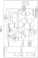
- FIG. 1 is a block diagram illustrating an internal configuration of an electronic control device and a power source IC in the present embodiment.
- an electronic control device 1 in the present embodiment includes a microcomputer (microcontroller) 2, a power source IC 3, sensors 4, and a peripheral circuit 5.
- the microcomputer 2 is the brain of the electronic control device 1, and controls the peripheral circuit 5 by using various control signals and various input signals.
- the microcomputer can write information in the register 12, change setting of the power source IC 3, transmit the state of the microcomputer 2 itself to the power source IC 3, read the information stored in the register 12, and check the state of the power source IC 3.
- the power source IC 3 generates a plurality of power source voltages from a battery voltage (not illustrated), and supplies the power source voltages of the microcomputer 2, other peripheral circuits 5, and an external sensor (not illustrated).
- a voltage generated by the power source circuit 15 is supplied to the microcomputer 2 as a power source voltage output 1 and a power source voltage output 2.
- the power source voltage output 3 is supplied to the peripheral circuit 5.
- the power source voltage outputs 1 to 3 are illustrated here, the power source voltage outputs may be supplied to different destinations or in different numbers.
- the power source circuit 15 and a drive circuit 17 are controlled by a sequencer 16, and the power source voltage outputs 1 to 3 and various safety control signals are activated in accordance with a determined activation sequence.
- the "safety control signal” is a control signal for controlling the system to be in a safe state when an abnormality has occurred inside or outside the electronic control device 1.
- Three signals are illustrated as the various safety control signals (safety control signals 1 to 3) in FIG. 1 , but the number may be different depending on the system to which the electronic control device 1 is applied.
- the power source voltage outputs 1 to 3 and the various safety control signals are output to the outside of the power source IC 3 and are also input to the diagnosis circuit 14 to diagnose whether or not an abnormality has occurred.
- the diagnosis of whether or not the an abnormality has occurred is performed at a diagnostic timing designated by the sequencer 16.
- the diagnosis circuit 14 diagnoses whether or not the input signal is a desired output.
- the diagnosis circuit 14 stores the diagnostic result in a diagnostic information register 20 region in the register 12, and/or outputs an abnormal state flag signal to the microcomputer 2 to report the abnormality.
- the information stored in the diagnostic information register 20 is reported to the microcomputer 2 by communication through the interface circuit 11.
- the power source IC 3 outputs the abnormal state flag signal to the microcomputer 2 and stops the power source voltage supplied to the microcomputer 2 so as not to activate the microcomputer 2.
- the monitoring circuit 18 is a circuit for the power source IC 3 to monitor the microcomputer 2.
- the microcomputer 2 stores the state of the microcomputer 2 in the register 12 through the interface circuit 11.
- the monitoring circuit 18 determines information of the microcomputer 2 stored in the register 12, and outputs, to the safety processing circuit 13, a microcomputer abnormality flag signal for a notification of whether or not the microcomputer 2 has an abnormality.
- the safety processing circuit 13 is a circuit that operates when the power source IC 3 detects an abnormality.
- the safety processing circuit 13 operates by using, as an input, the microcomputer abnormality flag signal from the monitoring circuit 18, the diagnostic result from the diagnosis circuit 14, and information such as the temperature from the sensors 4.
- the safety processing circuit 13 directly controls the drive circuit 17, and causes the system to transition to a safe state by a safety control signal in which no abnormality occurs.
- thermoelectric information have been described as the signal from the sensors 4, for example, current or voltage information other than the temperature information may be used, or information from a plurality of sensors may be used.
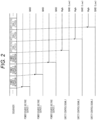
- FIG. 2 is a timing chart illustrating an activation sequence of the power source IC 3 illustrated in FIG. 1 . The activation of the power source IC 3 will be described with reference to FIG. 2 .
- the internal state of the power source IC 3 illustrated in the timing chart of FIG. 2 is determined by the sequencer 16.
- the power source voltage outputs 1 to 3 and the safety control signals 1 to 3 are sequentially activated as illustrated in FIG. 2 in accordance with the state changing in the order of activation of power sources 1 to 3 and activation of the safety control signals 1 to 3.
- a method for determination an abnormality of the safety control signal by the diagnosis circuit 14 will be described.
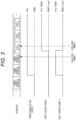
- FIG. 3 is a timing chart illustrating an operation example when the safety control signal output from the power source IC 3 in a normal state.
- the level of the power source voltage output 2 after activation is set as Vcc
- the High level of the safety control signal 1 is set as Vcc
- the Low level is set as GND.
- the safety control signal 1x illustrated in FIG. 3 is a negative logic signal, and indicates that a certain function is valid at a Low level and indicates that a certain function is invalid at a High level.
- the safety control signal 1x is also used to describe a case where the safety control signal is negative logic.
- the power source voltage output 2 is activated in the state of activation of the power source 2. Then, in the state of activation of the safety control signal 1, the safety control signal 1 is activated to the Vcc level, and the safety control signal 1x is activated to the GND level.
- the safety control signal 1x transitions to the Vcc level, which is the initial state of the negative logic signal, at a timing at which the power source voltage output 2 is activated.
- the safety control signal is diagnosed by checking signal levels before and after the activation of the safety control signal.
- the signal level before the activation is checked at a level check timing 1 that is in the state of activation of the power source 3, and the signal level after the activation is checked at a level check timing 2 that is in the state of activation of the safety control signal 1.
- the signal level of the safety control signal 1 before activation is GND (Low level)
- the signal level of the safety control signal 1 after activation is Vcc (High level)
- the signal level of the safety control signal 1x before activation is Vcc (High level)
- the signal level of the safety control signal 1x after activation is GND (Low level). That is, when the safety control signal operates normally, the diagnosis circuit 14 determines that the determination result is normal under the condition that the signal levels before and after activation are different.
- FIG. 4 is a timing chart illustrating an operation example when the control signal output from the power source IC 3 is in a High fixation abnormal state.
- the level of the safety control signal is defined similarly to FIG. 3 , and the same applies to the timing of the level check of the signal.
- the power source voltage output 2 is activated in the state of activation of the power source 2. Then, in the state of the activation of the safety control signal 1, the safety control signal 1 and the safety control signal 1x are activated. However, when the power source voltage output 2, and the safety control signal 1 or the safety control signal 1x are fixed, the safety control signal 1/the safety control signal 1x operates similarly to the power source voltage output 2.
- the safety control signal 1/safety control signal 1x is at the level of Vcc before the original activation timing. That is, when High fixation abnormality occurs in the safety control signal, the diagnosis circuit 14 determines the determination result to have a High fixation abnormality under the condition that both the signal levels before and after activation are Vcc (High level).
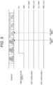
- FIG. 5 is a timing chart illustrating an operation example when the control signal output from the power source IC 3 is in a Low fixation abnormal state.
- the level of the safety control signal is defined similarly to FIG. 3 , and the same applies to the timing of the level check of the signal.
- the power source voltage output 2 is activated in the state of activation of the power source 2. Then, in the state of the activation of the safety control signal 1, the safety control signal 1 and the safety control signal 1x are activated. However, when GND (Low level), and the safety control signal 1 or the safety control signal 1x are fixed, the safety control signal 1/the safety control signal 1x operates similarly to GND.
- the safety control signal 1/safety control signal 1x is at the level of GND even after the activation timing. That is, when Low fixation abnormality occurs in the safety control signal, the diagnosis circuit 14 determines the determination result to have a Low fixation abnormality under the condition that both the signal levels before and after activation are GND (Low level).
- FIG. 6 is a timing chart illustrating an operation example of fixation diagnosis of the safety control signals output from the power source IC 3.
- fixation diagnosis of the safety control signal 1 and the safety control signal 2 is performed will be described.
- the signal level before activation of the safety control signal 2 is GND (Low level)/the signal level after activation is Vcc (High level), and the levels before and after activation are different, so that the diagnosis circuit 14 determines that no abnormality occurs.
- (b) of the drawing illustrates an operation example in an abnormal state, and illustrates an operation when the safety control signal 1 and the safety control signal 2 are fixed.
- the safety control signal 2 operates similarly to the safety control signal 1, and transitions to Vcc (High level) at the timing at which the safety control signal 1 is activated.
- FIG. 7 is a timing chart illustrating another operation example of fixation diagnosis of the safety control signals output from the power source IC 3.
- the safety control signal 2x is a negative logic signal.
- the signal level before activation of the safety control signal 2 is Vcc (High level)/the signal level after activation is GND (Low level), and the levels before and after activation are different, so that the diagnosis circuit 14 diagnoses that the output of the safety control signal is normal.
- (b) of the drawing illustrates an operation example in an abnormal state, and illustrates an operation when the safety control signal 1 and the safety control signal 2x are fixed. In this case, the safety control signal 1 and the safety control signal 2x operate similarly.
- the electronic control device 1 in the present embodiment includes the microcomputer 2 and the power source IC 3 that communicates with the microcomputer 2.
- the power source IC 3 includes the monitoring circuit 18 that monitors the microcomputer 2, the safety processing circuit 13 that outputs the safety control signal when the monitoring circuit 18 determines the occurrence of an abnormality in the microcomputer, and the diagnosis circuit 14 that diagnoses whether or not the safety control signal has a fixation failure.
- the diagnosis circuit 14 detects whether or not the fixation failure has occurred, based on states of the safety control signal before and after the safety control signal is activated after activation of the power source.
- the diagnosis circuit 14 detects the state of the safety control signal in a period after the power source is activated and before the safety control signal is activated, detects the state of the safety control signal in a period after the safety control signal is activated, and compares the states before and after the activation of the safety control signal, thereby diagnosing whether or not the safety control signal has the fixation failure.
- the diagnosis circuit 14 completes the diagnosis of the safety control signal by the diagnosis circuit 14 before the microcomputer 2 is activated.
- the power source IC 3 controls the safety control signal in which the fixation failure is not detected, and transitions the system being the control target of the electronic control device 1 to a safe state.
- the present embodiment it is possible to perform the fixation diagnosis of the safety control signal of the power source IC 3 before the microcomputer 2 is activated, and to safely control the electronic control device 1 and the system being the control target of the electronic control device 1.
- the present embodiment is an example of an engine electronic control device in which the electronic control device of the first embodiment is applied to engine control.
- FIG. 8 is a block diagram illustrating an internal configuration of an engine electronic control device according to the present embodiment.
- an electronic control device 1A in the present embodiment includes drivers 6A and 6B for driving an electronic control throttle 21 and an injector 24, respectively, in addition to the configuration of the electronic control device 1 in the first embodiment ( FIG. 1 ).
- the drivers 6A and 6B are controlled by a driver control signal from the microcomputer 2.
- the drive circuit 17 outputs a reset signal, an electronic control throttle enable signal, and an injector enable signal, as the safety control signals.
- the reset signal is used to reset the microcomputer 2.
- the electronic control throttle enable signal is input to the driver 6A, and switches enabling/disabling of the control of the electronic control throttle 21 by the microcomputer 2.
- the injector enable signal is input to the driver 6B, and switches enabling/disabling of the control of the injector 24 by the microcomputer 2.
- the electronic control throttle 21 is a valve that electronically controls the amount of intake air flowing into an engine and adjusts the output of the engine.
- the electronic control throttle 21 adjusts the amount of air taken in from the outside and sends the air toward the engine.
- the injector 24 is used to atomize and pump fuel into a cylinder of the engine.
- the fuel supplied from the fuel tank 23 is pressurized by a high-pressure pump 22 and injected in an atomized state by passing through the injector 24.
- the electronic control throttle enable signal can be used to stop the electronic control throttle 21 so as to block the air supplied to the engine, or the injector enable signal can be used to stop the injector 24 so as to block the fuel supplied to the engine. Further, by resetting the microcomputer 2 using the reset signal, the electronic control throttle 21 and the injector 24 can be controlled and safely stopped.
- the electronic control throttle enable signal and the injector enable signal are set to be active by raising the enable signal (safety control signal) one by one after all the internal power sources of the power source IC 3 are activated.
- the present embodiment is an example of an inverter electronic control device in which the electronic control device in the first embodiment is applied to motor control of an electric vehicle.
- FIG. 9 is a block diagram illustrating an internal configuration of an inverter electronic control device according to the present embodiment.
- an electronic control device 1B in the present embodiment includes, in addition to the configuration of the electronic control device 1 in the first embodiment ( FIG. 1 ), a power module 8 for driving a motor 26, a gate driver 7 for controlling the power module 8, a capacitor 10 that stores electric charges from an HV (high voltage) battery 25, and a discharge circuit 9 for discharging the electric charge stored in the capacitor 10.
- a power module 8 for driving a motor 26
- a gate driver 7 for controlling the power module 8
- a capacitor 10 that stores electric charges from an HV (high voltage) battery 25
- a discharge circuit 9 for discharging the electric charge stored in the capacitor 10.
- the drive circuit 17 outputs a reset signal, a gate driver control signal, and an active discharge signal as the safety control signals.
- the reset signal is used to reset the microcomputer 2.
- the motor that is generally used in the electric vehicle is a three-phase AC motor, and three types of drive signals are required. Therefore, three power modules 8 are actually required.
- two transistors are mounted on one power module, and in order to control the three power modules, six gate drivers are used and control is performed by six control signals.
- the gate driver 7 is controlled by the gate driver control signal output from the drive circuit 17.
- the motor 26 is safely stopped by controlling the power module 8.
- the discharge circuit 9 is controlled by controlling the active discharge signal, and the electric charges stored in the capacitor 10 from the HV battery 25 are safely discharged.
- by resetting the microcomputer 2 using the reset signal it is possible to safely stop the system to which the electronic control device 1B is applied.
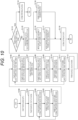
- FIG. 10 is a flowchart illustrating a processing operation example until activation is performed in a system to which the electronic control device 1 in the first embodiment ( FIG. 1 ) is applied.
- Step S101 When power is supplied to the electronic control device 1 (Step S100), the power source IC 3 starts activation (Step S101) .
- Step S102 When starting activation, the power source IC 3 starts activation of the generated internal power sources in order (Step S102).
- Step S103 When the activation of one internal power source is completed (Step S103), the remaining internal power sources are also activated in order.
- Step S104 When the activation of all the internal power sources is completed (Step S104), the safety control signal is activated.
- Step S104 the process returns to Step S102, and each internal power source is activated in order.
- the safety control signals output from the power source IC 3 also start to be activated one by one in order (Step S105) .
- the level check of the safety control signal is first performed before activation (Step S106).
- Step S107 the level check of the safety control signal after activation is performed (Step S108).
- fixation diagnosis of the safety control signal is performed by using the result of the level check performed before and after activation (Step S109), and the state of the safety control signal for which diagnosis has been performed is stored in the register 12 regardless of the diagnostic result (Step S110).
- the processing up to this step is performed on each safety control signal, and the activation of the safety control signal is ended (Step S111).
- the activation of the power source IC 3 is ended (Step S112).
- the process returns to Step S105, and the safety control signals are activated in order.
- the power source IC 3 checks whether there is no fixation abnormality in the safety control signal (Step S113) .
- the process transitions to activation of the system (Step S114).
- the fixation abnormality diagnosis flag signal is output to the microcomputer 2 (Step S115), and microcomputer 2 is notified of the abnormality.
- the microcomputer 2 detects an abnormality in the safety control signal by the register information and the fixation abnormality diagnosis flag signal stored in Step S110 (Step S116).
- the microcomputer 2 executes a response process in the abnormal state (Step S117), and controls to stop the system in a safe state (Step S119) .
- the power source IC 3 After outputting the fixation abnormality diagnosis flag signal, the power source IC 3 performs an operation set (designated) in advance by the register 12 or the like (Step S118), and can perform control to stop the system in a safe state (Step S119) .
- the preset operation for example, there are a plurality of possibilities of performing nothing, stopping the voltage output output to the outside, outputting the safety control signal to safely stop the system, and the like.
- the safety control signal in the present embodiment includes at least one of the reset signal to the microcomputer 2, the enable signal to the injector 24, the enable signal to the electronic control throttle 21, the control signal of the gate driver (IC) 7, and the signal related to active discharge, which have been described in the first to third embodiments.
- control lines and information lines considered necessary for the descriptions are illustrated, and not all the control lines and the information lines in the product are necessarily shown.
- the configuration of the functional block is merely an example. Some functional configurations illustrated as separate functional blocks may be integrally configured, or a configuration illustrated in one functional block diagram may be divided into two or more functions. In addition, some of the functions in each functional block may be included in another functional block.
Landscapes
- Engineering & Computer Science (AREA)
- Theoretical Computer Science (AREA)
- Automation & Control Theory (AREA)
- Physics & Mathematics (AREA)
- General Physics & Mathematics (AREA)
- General Engineering & Computer Science (AREA)
- Human Computer Interaction (AREA)
- Transportation (AREA)
- Mechanical Engineering (AREA)
- Computing Systems (AREA)
- Quality & Reliability (AREA)
- Safety Devices In Control Systems (AREA)
- Microcomputers (AREA)
Abstract
Description
- The present invention relates to a configuration of an electronic control device and control thereof, and particularly relates to a technique effective for application to an in-vehicle electronic control device requiring high reliability.
- In recent years, a vehicle having a driving support function for supporting a steering operation and acceleration/deceleration, a hybrid vehicle that operates by using a motor in addition to a conventional engine, or an electric vehicle that operates only with a motor have started to spread. Such vehicles have electronic control more complicated than conventional vehicles. When a failure of an electronic component occurs, more advanced safety control is required to safely stop the vehicle.
- In the electronic control devices for such vehicles, when the occurrence of a failure is detected, control for safely stopping a motor, an engine, and the like through a safety control signal is performed, and it is important to diagnose whether or not the safety control signal normally functions.
- As the related art of the present technical field, for example, there is a technique such as
PTL 1.PTL 1 discloses "a semiconductor device including: a control circuit that outputs a start signal of power supply; a power supply unit that starts supply of a power source voltage in response to the start signal; a timer that counts time in response to the start signal and outputs a count value; a first voltage comparator that compares a first predetermined voltage value with a voltage value supplied from the power supply unit and outputs the result as a first comparison signal; a second voltage comparator that compares a second predetermined voltage value with the voltage value supplied from the power supply unit and outputs the result as a second comparison signal; and an abnormality determination unit that detects whether or not an abnormality has occurred, based on the count value, the first comparison signal, and the second comparison signal". - PTL 1:
JP 2017-149244 A - As described above, the risk of malfunction of a system is increasing with complication and enlargement of an automobile control system. When a failure occurs in a control function of an automobile control system, not only a driver and a passenger but also the entire periphery including a pedestrian is in danger. Thus, improvement of reliability of individual components constituting the system and improvement of reliability of a safety control function such as a safety control signal are important issues.
- The invention disclosed in
PTL 1 is effective for abnormality detection of the power source itself, but there is room for improvement in abnormality detection of output signals other than the output of the power source. - Therefore, an object of the present invention is to provide an electronic control device and a method for diagnosing the electronic control device that has high reliability and is capable of performing fixation diagnosis of a safety control signal of a power source IC before activation of a microcomputer in the electronic control device on which the microcomputer and the power source IC are mounted.
- To solve the above problems, the present invention includes a microcomputer, and a power source IC that communicates with the microcomputer. The power source IC includes a monitoring circuit that monitors the microcomputer, a safety processing circuit that outputs a safety control signal when the monitoring circuit determines an occurrence of an abnormality in the microcomputer, and a diagnosis circuit that diagnoses whether or not the safety control signal has a fixation failure. The diagnosis circuit detects whether or not the fixation failure has occurred, based on states of the safety control signal before and after the safety control signal is activated after activation of a power source.
- Further, according to the present invention, there is provided a method for diagnosing an electronic control device including a microcomputer and a power source IC that communicates with the microcomputer. The power source IC activates internal power sources one by one before the microcomputer is activated. After all the internal power sources are activated, the power source IC activates safety control signals one by one. The power source IC detects whether or not a fixation failure has occurred in the safety control signals based on states of the safety control signals before and after the safety control signal corresponding to the internal power source is activated after activation of a predetermined internal power source.
- According to the present invention, it is possible to realize an electronic control device and a method for diagnosing the electronic control device that has high reliability and is capable of performing fixation diagnosis of a safety control signal of a power source IC before activation of a microcomputer in the electronic control device on which the microcomputer and the power source IC are mounted.
- As a result, it is possible to detect an occurrence of an abnormality in the electronic control device before a vehicle is operated, and to perform safety control in response to the abnormality.
- Objects, configurations, and advantageous effects other than those described above will be clarified by the descriptions of the following embodiments.
-
- [
FIG. 1] FIG. 1 is a block diagram illustrating an internal configuration of an electronic control device and a power source IC according to a first embodiment of the present invention. - [
FIG. 2] FIG. 2 is a timing chart of an activation sequence of the electronic control device illustrated inFIG. 1 . - [
FIG. 3] FIG. 3 is a timing chart of a safety control signal in the electronic control device illustrated inFIG. 1 . (in a normal state) - [
FIG. 4] FIG. 4 is a timing chart of the safety control signal in the electronic control device illustrated inFIG. 1 . (in a High fixation abnormal state) - [
FIG. 5] FIG. 5 is a timing chart of the safety control signal in the electronic control device illustrated inFIG. 1 . (in a Low fixation abnormal state) - [
FIG. 6] FIG. 6 is a timing chart of an operation example of fixation diagnosis of safety control signals in the electronic control device illustrated inFIG. 1 . - [
FIG. 7] FIG. 7 is a timing chart illustrating an operation example of fixation diagnosis of the safety control signals in the electronic control device illustrated inFIG. 1 . - [
FIG. 8] FIG. 8 is a block diagram illustrating an internal configuration of an engine electronic control device according to a second embodiment of the present invention. - [
FIG. 9] FIG. 9 is a block diagram illustrating an internal configuration of an inverter electronic control device according to a third embodiment of the present invention. - [
FIG. 10 ] FIG. is a flowchart of a method for diagnosing an electronic control device according to a fourth embodiment of the present invention. - Hereinafter, embodiments of the present invention will be described with reference to the drawings. In the drawings, the same components are denoted by the same reference signs, and the detailed description of the repetitive parts will be omitted.
- An electronic control device and a diagnosis method thereof according to a first embodiment of the present invention will be described with reference to
FIGS. 1 to 7 .FIG. 1 is a block diagram illustrating an internal configuration of an electronic control device and a power source IC in the present embodiment. - As illustrated in
FIG. 1 , anelectronic control device 1 in the present embodiment includes a microcomputer (microcontroller) 2, apower source IC 3,sensors 4, and aperipheral circuit 5. - The
microcomputer 2 is the brain of theelectronic control device 1, and controls theperipheral circuit 5 by using various control signals and various input signals. In addition, by communicating with the power source IC 3 through aninterface circuit 11, the microcomputer can write information in theregister 12, change setting of the power source IC 3, transmit the state of themicrocomputer 2 itself to the power source IC 3, read the information stored in theregister 12, and check the state of the power source IC 3. - The
power source IC 3 generates a plurality of power source voltages from a battery voltage (not illustrated), and supplies the power source voltages of themicrocomputer 2, otherperipheral circuits 5, and an external sensor (not illustrated). InFIG. 1 , for example, a voltage generated by thepower source circuit 15 is supplied to themicrocomputer 2 as a powersource voltage output 1 and a powersource voltage output 2. In addition, the powersource voltage output 3 is supplied to theperipheral circuit 5. Although the powersource voltage outputs 1 to 3 are illustrated here, the power source voltage outputs may be supplied to different destinations or in different numbers. - The
power source circuit 15 and adrive circuit 17 are controlled by asequencer 16, and the powersource voltage outputs 1 to 3 and various safety control signals are activated in accordance with a determined activation sequence. - Here, the "safety control signal" is a control signal for controlling the system to be in a safe state when an abnormality has occurred inside or outside the
electronic control device 1. Three signals are illustrated as the various safety control signals (safety control signals 1 to 3) inFIG. 1 , but the number may be different depending on the system to which theelectronic control device 1 is applied. - The power source voltage outputs 1 to 3 and the various safety control signals (
safety control signals 1 to 3) are output to the outside of thepower source IC 3 and are also input to thediagnosis circuit 14 to diagnose whether or not an abnormality has occurred. In addition, the diagnosis of whether or not the an abnormality has occurred is performed at a diagnostic timing designated by thesequencer 16. Thediagnosis circuit 14 diagnoses whether or not the input signal is a desired output. When the abnormality has occurred, thediagnosis circuit 14 stores the diagnostic result in adiagnostic information register 20 region in theregister 12, and/or outputs an abnormal state flag signal to themicrocomputer 2 to report the abnormality. In addition, the information stored in thediagnostic information register 20 is reported to themicrocomputer 2 by communication through theinterface circuit 11. When thediagnosis circuit 14 detects the fixation failure in the safety control signal, thepower source IC 3 outputs the abnormal state flag signal to themicrocomputer 2 and stops the power source voltage supplied to themicrocomputer 2 so as not to activate themicrocomputer 2. - The
monitoring circuit 18 is a circuit for thepower source IC 3 to monitor themicrocomputer 2. Themicrocomputer 2 stores the state of themicrocomputer 2 in theregister 12 through theinterface circuit 11. Themonitoring circuit 18 determines information of themicrocomputer 2 stored in theregister 12, and outputs, to thesafety processing circuit 13, a microcomputer abnormality flag signal for a notification of whether or not themicrocomputer 2 has an abnormality. - The
safety processing circuit 13 is a circuit that operates when thepower source IC 3 detects an abnormality. Thesafety processing circuit 13 operates by using, as an input, the microcomputer abnormality flag signal from themonitoring circuit 18, the diagnostic result from thediagnosis circuit 14, and information such as the temperature from thesensors 4. When a signal indicating the occurrence of the abnormality is input, thesafety processing circuit 13 directly controls thedrive circuit 17, and causes the system to transition to a safe state by a safety control signal in which no abnormality occurs. - Here, three types of signals have been described as the input of the
safety processing circuit 13, but any one type or a combination of any two types may be used. Although temperature information have been described as the signal from thesensors 4, for example, current or voltage information other than the temperature information may be used, or information from a plurality of sensors may be used. -
FIG. 2 is a timing chart illustrating an activation sequence of thepower source IC 3 illustrated inFIG. 1 . The activation of thepower source IC 3 will be described with reference toFIG. 2 . - The internal state of the
power source IC 3 illustrated in the timing chart ofFIG. 2 is determined by thesequencer 16. The powersource voltage outputs 1 to 3 and thesafety control signals 1 to 3 are sequentially activated as illustrated inFIG. 2 in accordance with the state changing in the order of activation ofpower sources 1 to 3 and activation of thesafety control signals 1 to 3. - A method for determination an abnormality of the safety control signal by the
diagnosis circuit 14 will be described. -
FIG. 3 is a timing chart illustrating an operation example when the safety control signal output from thepower source IC 3 in a normal state. Here, the level of the powersource voltage output 2 after activation is set as Vcc, the High level of thesafety control signal 1 is set as Vcc, and the Low level is set as GND. Thesafety control signal 1x illustrated inFIG. 3 is a negative logic signal, and indicates that a certain function is valid at a Low level and indicates that a certain function is invalid at a High level. Thesafety control signal 1x is also used to describe a case where the safety control signal is negative logic. - According to the state indicated by the sequencer (16) in
FIG. 3 , the powersource voltage output 2 is activated in the state of activation of thepower source 2. Then, in the state of activation of thesafety control signal 1, thesafety control signal 1 is activated to the Vcc level, and thesafety control signal 1x is activated to the GND level. Here, thesafety control signal 1x transitions to the Vcc level, which is the initial state of the negative logic signal, at a timing at which the powersource voltage output 2 is activated. - The safety control signal is diagnosed by checking signal levels before and after the activation of the safety control signal.
- In
FIG. 1 , the signal level before the activation is checked at alevel check timing 1 that is in the state of activation of thepower source 3, and the signal level after the activation is checked at alevel check timing 2 that is in the state of activation of thesafety control signal 1. - If the safety control signal is normally activated according to the sequencer (16), the signal level of the
safety control signal 1 before activation is GND (Low level), the signal level of thesafety control signal 1 after activation is Vcc (High level), the signal level of thesafety control signal 1x before activation is Vcc (High level), and the signal level of thesafety control signal 1x after activation is GND (Low level). That is, when the safety control signal operates normally, thediagnosis circuit 14 determines that the determination result is normal under the condition that the signal levels before and after activation are different. -
FIG. 4 is a timing chart illustrating an operation example when the control signal output from thepower source IC 3 is in a High fixation abnormal state. Here, it is assumed that the level of the safety control signal is defined similarly toFIG. 3 , and the same applies to the timing of the level check of the signal. - According to the state indicated by the sequencer (16), the power
source voltage output 2 is activated in the state of activation of thepower source 2. Then, in the state of the activation of thesafety control signal 1, thesafety control signal 1 and thesafety control signal 1x are activated. However, when the powersource voltage output 2, and thesafety control signal 1 or thesafety control signal 1x are fixed, thesafety control signal 1/thesafety control signal 1x operates similarly to the powersource voltage output 2. - Therefore, the
safety control signal 1/safety control signal 1x is at the level of Vcc before the original activation timing. That is, when High fixation abnormality occurs in the safety control signal, thediagnosis circuit 14 determines the determination result to have a High fixation abnormality under the condition that both the signal levels before and after activation are Vcc (High level). -
FIG. 5 is a timing chart illustrating an operation example when the control signal output from thepower source IC 3 is in a Low fixation abnormal state. Here, it is assumed that the level of the safety control signal is defined similarly toFIG. 3 , and the same applies to the timing of the level check of the signal. - According to the internal state of the
power source IC 3, the powersource voltage output 2 is activated in the state of activation of thepower source 2. Then, in the state of the activation of thesafety control signal 1, thesafety control signal 1 and thesafety control signal 1x are activated. However, when GND (Low level), and thesafety control signal 1 or thesafety control signal 1x are fixed, thesafety control signal 1/thesafety control signal 1x operates similarly to GND. - Therefore, the
safety control signal 1/safety control signal 1x is at the level of GND even after the activation timing. That is, when Low fixation abnormality occurs in the safety control signal, thediagnosis circuit 14 determines the determination result to have a Low fixation abnormality under the condition that both the signal levels before and after activation are GND (Low level). -
FIG. 6 is a timing chart illustrating an operation example of fixation diagnosis of the safety control signals output from thepower source IC 3. Here, a case where the fixation diagnosis of thesafety control signal 1 and thesafety control signal 2 is performed will be described. - (a) of the drawing illustrates an operation example in a normal state. According to the sequencer (16), the
safety control signal 1 is activated in the state of activation of thesafety control signal 1, and thesafety control signal 2 is activated in the state of activation of thesafety control signal 2. By checking signal levels before and after activation of thesafety control signal 2 to be activated later, fixation with thesafety control signal 1 is checked. That is, the signal level before the activation is checked at alevel check timing 1 that is in the state of activation of thesafety control signal 1, and the signal level after the activation is checked at alevel check timing 2 that is in the state of activation of thesafety control signal 2. - The signal level before activation of the
safety control signal 2 is GND (Low level)/the signal level after activation is Vcc (High level), and the levels before and after activation are different, so that thediagnosis circuit 14 determines that no abnormality occurs.
(b) of the drawing illustrates an operation example in an abnormal state, and illustrates an operation when thesafety control signal 1 and thesafety control signal 2 are fixed. In this case, thesafety control signal 2 operates similarly to thesafety control signal 1, and transitions to Vcc (High level) at the timing at which thesafety control signal 1 is activated. (a) Similarly to the normal state, when the signal level is checked at thelevel check timing 1/2 before and after the original activation timing of thesafety control signal 2, both the signal levels before and after the activation are Vcc (High level), and the levels before and after the activation are the same, so that thediagnosis circuit 14 determines that the fixation abnormality has occurred in the safety control signal. -
FIG. 7 is a timing chart illustrating another operation example of fixation diagnosis of the safety control signals output from thepower source IC 3. Here, a case where the fixation diagnosis of thesafety control signal 1 and thesafety control signal 2x is performed will be described. Thesafety control signal 2x is a negative logic signal. - (a) of the drawing illustrates an operation example in a normal state. According to the sequencer (16), the
safety control signal 1 is activated in the state of activation of thesafety control signal 1, and thesafety control signal 2x is activated in the state of activation of thesafety control signal 2. Thesafety control signal 2x transitions to Vcc (High level), which is an initial state, at the timing when the powersource voltage output 2 is activated. Similarly toFIG. 6 , the signal level before the activation is checked at alevel check timing 1 that is the timing before and after activation of thesafety control signal 2x to be activated later, and the signal level after the activation is checked at thelevel check timing 2 that is in the state of activation of thesafety control signal 2. - The signal level before activation of the
safety control signal 2 is Vcc (High level)/the signal level after activation is GND (Low level), and the levels before and after activation are different, so that thediagnosis circuit 14 diagnoses that the output of the safety control signal is normal.
(b) of the drawing illustrates an operation example in an abnormal state, and illustrates an operation when thesafety control signal 1 and thesafety control signal 2x are fixed. In this case, thesafety control signal 1 and thesafety control signal 2x operate similarly. (a) Similarly to the normal state, when the signal level is checked at thelevel check timing 1/2 before and after the original activation timing of thesafety control signal 2, both the signal levels before and after the activation are Vcc (High level), and the levels before and after the activation are the same, so that thediagnosis circuit 14 determines that the fixation abnormality has occurred in the safety control signal. - It is possible to diagnose whether or not a short circuit has occurred in the internal power source of the
power source IC 3 and the safety control signal by diagnosing whether or not various safety control signals have a fixation failure before the safety control signal rises. In addition, it is possible to diagnose whether or not a short circuit has occurred between thesafety control signal 1 and thesafety control signal 1x as illustrated inFIG. 3 by diagnosing whether or not various safety control signals have a fixation failure after the safety control signal rises. - As described above, the
electronic control device 1 in the present embodiment includes themicrocomputer 2 and thepower source IC 3 that communicates with themicrocomputer 2. Thepower source IC 3 includes themonitoring circuit 18 that monitors themicrocomputer 2, thesafety processing circuit 13 that outputs the safety control signal when themonitoring circuit 18 determines the occurrence of an abnormality in the microcomputer, and thediagnosis circuit 14 that diagnoses whether or not the safety control signal has a fixation failure. Thediagnosis circuit 14 detects whether or not the fixation failure has occurred, based on states of the safety control signal before and after the safety control signal is activated after activation of the power source. - In addition, the
diagnosis circuit 14 detects the state of the safety control signal in a period after the power source is activated and before the safety control signal is activated, detects the state of the safety control signal in a period after the safety control signal is activated, and compares the states before and after the activation of the safety control signal, thereby diagnosing whether or not the safety control signal has the fixation failure. - The
diagnosis circuit 14 completes the diagnosis of the safety control signal by thediagnosis circuit 14 before themicrocomputer 2 is activated. - Then, the
power source IC 3 controls the safety control signal in which the fixation failure is not detected, and transitions the system being the control target of theelectronic control device 1 to a safe state. - According to the present embodiment, it is possible to perform the fixation diagnosis of the safety control signal of the
power source IC 3 before themicrocomputer 2 is activated, and to safely control theelectronic control device 1 and the system being the control target of theelectronic control device 1. - An electronic control device and control thereof according to a second embodiment of the present invention will be described with reference to
FIG. 8 . - The present embodiment is an example of an engine electronic control device in which the electronic control device of the first embodiment is applied to engine control.
FIG. 8 is a block diagram illustrating an internal configuration of an engine electronic control device according to the present embodiment. - As illustrated in
FIG. 8 , anelectronic control device 1A in the present embodiment includesdrivers electronic control throttle 21 and aninjector 24, respectively, in addition to the configuration of theelectronic control device 1 in the first embodiment (FIG. 1 ). Thedrivers microcomputer 2. - The
drive circuit 17 outputs a reset signal, an electronic control throttle enable signal, and an injector enable signal, as the safety control signals. The reset signal is used to reset themicrocomputer 2. The electronic control throttle enable signal is input to thedriver 6A, and switches enabling/disabling of the control of theelectronic control throttle 21 by themicrocomputer 2. The injector enable signal is input to thedriver 6B, and switches enabling/disabling of the control of theinjector 24 by themicrocomputer 2. - The
electronic control throttle 21 is a valve that electronically controls the amount of intake air flowing into an engine and adjusts the output of the engine. Theelectronic control throttle 21 adjusts the amount of air taken in from the outside and sends the air toward the engine. - The
injector 24 is used to atomize and pump fuel into a cylinder of the engine. The fuel supplied from thefuel tank 23 is pressurized by a high-pressure pump 22 and injected in an atomized state by passing through theinjector 24. - When an abnormality has occurred in the
electronic control device 1A, the electronic control throttle enable signal can be used to stop theelectronic control throttle 21 so as to block the air supplied to the engine, or the injector enable signal can be used to stop theinjector 24 so as to block the fuel supplied to the engine. Further, by resetting themicrocomputer 2 using the reset signal, theelectronic control throttle 21 and theinjector 24 can be controlled and safely stopped. - As described in the first embodiment (
FIG. 3 ), the electronic control throttle enable signal and the injector enable signal are set to be active by raising the enable signal (safety control signal) one by one after all the internal power sources of thepower source IC 3 are activated. - In addition, if the reset signal output from the
drive circuit 17 is activated last with respect to other safety control signals, it is possible to perform abnormality diagnosis of all the safety control signals before the system is activated. - An electronic control device and control thereof according to a third embodiment of the present invention will be described with reference to
FIG. 9 . - The present embodiment is an example of an inverter electronic control device in which the electronic control device in the first embodiment is applied to motor control of an electric vehicle.
FIG. 9 is a block diagram illustrating an internal configuration of an inverter electronic control device according to the present embodiment. - As illustrated in
FIG. 9 , anelectronic control device 1B in the present embodiment includes, in addition to the configuration of theelectronic control device 1 in the first embodiment (FIG. 1 ), a power module 8 for driving amotor 26, a gate driver 7 for controlling the power module 8, acapacitor 10 that stores electric charges from an HV (high voltage)battery 25, and a discharge circuit 9 for discharging the electric charge stored in thecapacitor 10. - The
drive circuit 17 outputs a reset signal, a gate driver control signal, and an active discharge signal as the safety control signals. The reset signal is used to reset themicrocomputer 2. - Although the main configuration of the
electronic control device 1B is omitted inFIG. 9 for easy understanding, the motor that is generally used in the electric vehicle is a three-phase AC motor, and three types of drive signals are required. Therefore, three power modules 8 are actually required. In addition, two transistors are mounted on one power module, and in order to control the three power modules, six gate drivers are used and control is performed by six control signals. - When an abnormality has occurred in the
electronic control device 1B, the gate driver 7 is controlled by the gate driver control signal output from thedrive circuit 17. Themotor 26 is safely stopped by controlling the power module 8. The discharge circuit 9 is controlled by controlling the active discharge signal, and the electric charges stored in thecapacitor 10 from theHV battery 25 are safely discharged. In addition, by resetting themicrocomputer 2 using the reset signal, it is possible to safely stop the system to which theelectronic control device 1B is applied. - In addition, if the reset signal output from the
drive circuit 17 is activated last with respect to other safety control signals, it is possible to perform abnormality diagnosis of all the safety control signals before the system is activated. - A representative control method (diagnosis method) of the electronic control device of the present invention will be described with reference to
FIG. 10. FIG. 10 is a flowchart illustrating a processing operation example until activation is performed in a system to which theelectronic control device 1 in the first embodiment (FIG. 1 ) is applied. - When power is supplied to the electronic control device 1 (Step S100), the
power source IC 3 starts activation (Step S101) . When starting activation, thepower source IC 3 starts activation of the generated internal power sources in order (Step S102). When the activation of one internal power source is completed (Step S103), the remaining internal power sources are also activated in order. When the activation of all the internal power sources is completed (Step S104), the safety control signal is activated. When the activation of all the internal power sources has not ended in Step S104, the process returns to Step S102, and each internal power source is activated in order. - The safety control signals output from the
power source IC 3 also start to be activated one by one in order (Step S105) . The level check of the safety control signal is first performed before activation (Step S106). When the activation of the safety control signal is completed (Step S107), the level check of the safety control signal after activation is performed (Step S108). Then, fixation diagnosis of the safety control signal is performed by using the result of the level check performed before and after activation (Step S109), and the state of the safety control signal for which diagnosis has been performed is stored in theregister 12 regardless of the diagnostic result (Step S110). The processing up to this step is performed on each safety control signal, and the activation of the safety control signal is ended (Step S111). Then, the activation of thepower source IC 3 is ended (Step S112). When the activation of all the safety control signals is not ended in Step S111, the process returns to Step S105, and the safety control signals are activated in order. - Here, the
power source IC 3 checks whether there is no fixation abnormality in the safety control signal (Step S113) . When there is no fixation abnormality (YES), the process transitions to activation of the system (Step S114). On the other hand, when there is the fixation abnormality (NO), the fixation abnormality diagnosis flag signal is output to the microcomputer 2 (Step S115), andmicrocomputer 2 is notified of the abnormality. Themicrocomputer 2 detects an abnormality in the safety control signal by the register information and the fixation abnormality diagnosis flag signal stored in Step S110 (Step S116). Themicrocomputer 2 executes a response process in the abnormal state (Step S117), and controls to stop the system in a safe state (Step S119) . - In addition, after outputting the fixation abnormality diagnosis flag signal, the
power source IC 3 performs an operation set (designated) in advance by theregister 12 or the like (Step S118), and can perform control to stop the system in a safe state (Step S119) . As the preset operation, for example, there are a plurality of possibilities of performing nothing, stopping the voltage output output to the outside, outputting the safety control signal to safely stop the system, and the like. - The safety control signal in the present embodiment includes at least one of the reset signal to the
microcomputer 2, the enable signal to theinjector 24, the enable signal to theelectronic control throttle 21, the control signal of the gate driver (IC) 7, and the signal related to active discharge, which have been described in the first to third embodiments. - In the above-described embodiments, control lines and information lines considered necessary for the descriptions are illustrated, and not all the control lines and the information lines in the product are necessarily shown.
- Furthermore, in each of the above-described embodiments, the configuration of the functional block is merely an example. Some functional configurations illustrated as separate functional blocks may be integrally configured, or a configuration illustrated in one functional block diagram may be divided into two or more functions. In addition, some of the functions in each functional block may be included in another functional block.
- In addition, the above-described embodiments may be combined. Although various embodiments have been described above, the present invention is not limited to these contents. Other forms considered within the scope of the technical idea of the present invention are also included in the scope of the present invention.
-
- 1, 1A, 1B
- electronic control device
- 2
- microcomputer (microcontroller)
- 3
- power source IC
- 4
- sensors
- 5
- peripheral circuit
- 6A, 6B
- driver
- 7
- gate driver (IC)
- 8
- power module
- 9
- discharge circuit
- 10
- capacitor
- 11
- interface circuit
- 12
- register
- 13
- safety processing circuit
- 14
- diagnosis circuit
- 15
- power source circuit
- 16
- sequencer
- 17
- drive circuit
- 18
- monitoring circuit
- 20
- diagnostic information register
- 21
- electronic control throttle
- 22
- high-pressure pump
- 23
- fuel tank
- 24
- injector
- 25
- HV (high voltage) battery
- 26
- motor
Claims (15)
- An electronic control device comprising:a microcomputer; anda power source IC that communicates with the microcomputer,wherein the power source IC includesa monitoring circuit that monitors the microcomputer,a safety processing circuit that outputs a safety control signal when the monitoring circuit determines an occurrence of an abnormality in the microcomputer, anda diagnosis circuit that diagnoses whether or not the safety control signal has a fixation failure, andthe diagnosis circuit detects whether or not the fixation failure has occurred, based on states of the safety control signal before and after the safety control signal is activated after activation of a power source.
- The electronic control device according to claim 1, wherein the safety control signal includes at least one of a reset signal to the microcomputer, an enable signal to an injector, an enable signal to an electronic control throttle, a control signal of a gate driver IC, and a signal related to active discharge.
- The electronic control device according to claim 1, wherein the diagnosis circuitdetects a state of the safety control signal in a period from activation of the power source to activation of the safety control signal,detects the state of the safety control signal in a period after the activation of the safety control signal, anddiagnoses whether or not the safety control signal has a fixation failure by comparing the states before and after the activation of the safety control signal.
- The electronic control device according to claim 1, wherein the power source IC includes a register that stores a diagnostic result of the diagnosis circuit.
- The electronic control device according to claim 1, wherein, when the diagnosis circuit detects a fixation failure of the safety control signal, the power source IC outputs an abnormal state flag signal to the microcomputer and does not activate the microcomputer.
- The electronic control device according to claim 5, wherein the power source IC does not activate the microcomputer by stopping a power source voltage supplied to the microcomputer.
- The electronic control device according to claim 1, wherein the diagnosis circuit completes diagnosis of the safety control signal by the diagnosis circuit before the microcomputer is activated.
- The electronic control device according to claim 1, wherein the power source IC controls the safety control signal in which no fixation failure is detected, and transitions a system being a control target of the electronic control device to a safe state.
- A method for diagnosing an electronic control device including a microcomputer and a power source IC that communicates with the microcomputer, the method comprising: by the power source IC,activating internal power sources one by one before the microcomputer is activated;after all the internal power sources are activated, activating safety control signals one by one; anddetecting whether or not a fixation failure has occurred in the safety control signals based on states of the safety control signals before and after the safety control signal corresponding to the internal power source is activated after activation of a predetermined internal power source.
- The method for diagnosing an electronic control device according to claim 9, wherein the safety control signal includes at least one of a reset signal to the microcomputer, an enable signal to an injector, an enable signal to an electronic control throttle, a control signal of a gate driver IC, and a signal related to active discharge.
- The method for diagnosing an electronic control device according to claim 9, further comprising:detecting a state of the safety control signal in a period from activation of the internal power source to activation of the safety control signal corresponding to the internal power source;detecting a state of the safety control signal in a period after the safety control signal is activated; anddiagnosing whether or not the safety control signal has a fixation failure by comparing the states before and after the activation of the safety control signal.
- The method for diagnosing an electronic control device according to claim 9, further comprising
storing a diagnostic result of the safety control signal in a register of the power source IC. - The method for diagnosing an electronic control device according to claim 9, further comprising
when a fixation failure of the safety control signal is detected, outputting an abnormal state flag signal to the microcomputer, and not activating the microcomputer. - The method for diagnosing an electronic control device according to claim 13, wherein the microcomputer is not activated by stopping a power source voltage supplied to the microcomputer.
- The method for diagnosing an electronic control device according to claim 9, further comprising
completing diagnosis of the safety control signal before the microcomputer is activated.
Applications Claiming Priority (2)
| Application Number | Priority Date | Filing Date | Title |
|---|---|---|---|
| JP2020160535 | 2020-09-25 | ||
| PCT/JP2021/017537 WO2022064753A1 (en) | 2020-09-25 | 2021-05-07 | Electronic control device, and method for diagnosing electronic control device |
Publications (2)
| Publication Number | Publication Date |
|---|---|
| EP4220311A1 true EP4220311A1 (en) | 2023-08-02 |
| EP4220311A4 EP4220311A4 (en) | 2024-11-13 |
Family
ID=80846303
Family Applications (1)
| Application Number | Title | Priority Date | Filing Date |
|---|---|---|---|
| EP21871888.0A Pending EP4220311A4 (en) | 2020-09-25 | 2021-05-07 | ELECTRONIC CONTROL DEVICE AND METHOD FOR DIAGNOSIS OF AN ELECTRONIC CONTROL DEVICE |
Country Status (5)
| Country | Link |
|---|---|
| US (1) | US12164352B2 (en) |
| EP (1) | EP4220311A4 (en) |
| JP (1) | JP7366284B2 (en) |
| CN (1) | CN116057478B (en) |
| WO (1) | WO2022064753A1 (en) |
Families Citing this family (2)
| Publication number | Priority date | Publication date | Assignee | Title |
|---|---|---|---|---|
| US12164354B2 (en) * | 2020-10-07 | 2024-12-10 | Hitachi Astemo, Ltd. | Electronic control device and method for diagnosing wake-up circuit |
| JP2024044801A (en) * | 2022-09-21 | 2024-04-02 | ラピステクノロジー株式会社 | Microcontrollers and Electronic Circuits |
Family Cites Families (24)
| Publication number | Priority date | Publication date | Assignee | Title |
|---|---|---|---|---|
| JP2000112581A (en) | 1998-10-05 | 2000-04-21 | Toyota Motor Corp | Electronic control unit |
| JP3897046B2 (en) * | 2005-01-28 | 2007-03-22 | 横河電機株式会社 | Information processing apparatus and information processing method |
| JP4692318B2 (en) * | 2005-04-20 | 2011-06-01 | 株式会社デンソー | Electronic control unit |
| JP2007125934A (en) | 2005-11-01 | 2007-05-24 | Toyota Motor Corp | Vehicle power supply |
| US7757135B2 (en) * | 2006-09-11 | 2010-07-13 | Mentor Graphics Corporation | Method and apparatus for storing and distributing memory repair information |
| JP5234115B2 (en) * | 2008-11-27 | 2013-07-10 | 富士通株式会社 | Information processing apparatus, processing unit switching method, and processing unit switching program |
| JP4820428B2 (en) * | 2009-03-26 | 2011-11-24 | 三菱電機株式会社 | Engine control device |
| JP4977740B2 (en) * | 2009-08-03 | 2012-07-18 | 日立オートモティブシステムズ株式会社 | Internal combustion engine control device |
| JP5404437B2 (en) * | 2010-01-13 | 2014-01-29 | 株式会社東芝 | Safety output device |
| JP5951429B2 (en) * | 2012-02-01 | 2016-07-13 | ルネサスエレクトロニクス株式会社 | Watchdog circuit, power supply IC, and watchdog monitoring system |
| US9218236B2 (en) * | 2012-10-29 | 2015-12-22 | Infineon Technologies Ag | Error signal handling unit, device and method for outputting an error condition signal |
| EP2720098B1 (en) * | 2012-10-10 | 2020-04-15 | Sick Ag | Safety system for a plant comprising a test signal path with return path |
| EP2813949B1 (en) * | 2013-06-11 | 2019-08-07 | ABB Schweiz AG | Multicore processor fault detection for safety critical software applications |
| JP5861991B2 (en) * | 2013-08-02 | 2016-02-16 | 株式会社デンソー | Vehicle control device |
| JP2015217911A (en) | 2014-05-21 | 2015-12-07 | 株式会社デンソー | Electronic control apparatus |
| JP6183341B2 (en) | 2014-12-03 | 2017-08-23 | 株式会社デンソー | Injector drive device |
| JP6439670B2 (en) | 2015-12-18 | 2018-12-19 | トヨタ自動車株式会社 | In-vehicle system |
| JP6531661B2 (en) | 2016-02-12 | 2019-06-19 | 株式会社デンソー | Abnormality monitoring apparatus and electric power steering apparatus using the same |
| JP2017149244A (en) | 2016-02-24 | 2017-08-31 | ローム株式会社 | Semiconductor device and operation method thereof, and electronic control system |
| JP6742192B2 (en) | 2016-08-09 | 2020-08-19 | 日立オートモティブシステムズ株式会社 | Electronic control unit |
| JP2018095022A (en) * | 2016-12-12 | 2018-06-21 | ボッシュ株式会社 | Relay diagnostic apparatus and relay diagnostic method |
| US10754740B2 (en) * | 2018-02-27 | 2020-08-25 | Nxp Usa, Inc. | Dynamic suppression of error detection in processor switch fabric |
| JP6984512B2 (en) | 2018-03-22 | 2021-12-22 | 株式会社デンソー | Electronic control device |
| US11726794B2 (en) | 2019-09-26 | 2023-08-15 | Hitachi Astemo, Ltd. | Preventing supply of power to a microcomputer of an electronic control device until capacitors are discharged |
-
2021
- 2021-05-07 CN CN202180054646.6A patent/CN116057478B/en active Active
- 2021-05-07 JP JP2022551133A patent/JP7366284B2/en active Active
- 2021-05-07 US US18/022,286 patent/US12164352B2/en active Active
- 2021-05-07 WO PCT/JP2021/017537 patent/WO2022064753A1/en not_active Ceased
- 2021-05-07 EP EP21871888.0A patent/EP4220311A4/en active Pending
Also Published As
| Publication number | Publication date |
|---|---|
| US12164352B2 (en) | 2024-12-10 |
| CN116057478A (en) | 2023-05-02 |
| WO2022064753A1 (en) | 2022-03-31 |
| EP4220311A4 (en) | 2024-11-13 |
| US20230324971A1 (en) | 2023-10-12 |
| JP7366284B2 (en) | 2023-10-20 |
| JPWO2022064753A1 (en) | 2022-03-31 |
| CN116057478B (en) | 2026-03-17 |
Similar Documents
| Publication | Publication Date | Title |
|---|---|---|
| JP3627609B2 (en) | Starter for vehicle occupant protection system | |
| JPH0674024B2 (en) | Control device for automobile driver restraint system | |
| US9676357B2 (en) | Diagnosis of integrated driver circuits | |
| CN101141125A (en) | Fet monitoring and protecting system | |
| US12164352B2 (en) | Electronic control device and method for diagnosing electronic control device | |
| JP5864822B2 (en) | Method for inspecting a supply circuit, an attached supply circuit for at least one ignition circuit, and an ignition circuit device | |
| US9353717B2 (en) | Engine control unit for driving an electric circuit and method | |
| KR102224076B1 (en) | Apparatus for diagnosing reserving charging function of battery and method thereof | |
| US10144303B2 (en) | Monitoring device for a vehicle and method for monitoring a vehicle | |
| CN115503418B (en) | Five-connection-valve functional safety circuit and method for chassis domain controller system | |
| US6879892B2 (en) | Electronic control system and method thereof | |
| US6949932B2 (en) | Method for monitoring a power supply of a control unit in a motor vehicle | |
| CN109690333B (en) | Electronic control device and method for diagnosing connection state of electronic control device | |
| JP3992648B2 (en) | AT control unit | |
| EP3653452B1 (en) | Apparatus for detecting vehicle buckle and vehicle system including same | |
| KR101039926B1 (en) | Vehicle Self Diagnosis Control System | |
| US7426430B2 (en) | Control unit for activating an occupant protection means in a motor vehicle and method for monitoring the proper functioning of a control unit preferably of this type | |
| US11905906B2 (en) | Load drive device and method of controlling fuel injection device | |
| KR101887904B1 (en) | An Apparatus And A Method For Detecting Short Circuit Of A Controller | |
| CN115211014A (en) | Boosting device | |
| US20010040783A1 (en) | Load drive apparatus | |
| JP2002272012A (en) | Vehicle electronic control unit | |
| JPH10287200A (en) | Occupant protection device | |
| WO2024246940A1 (en) | An intelligent energy management system for a vehicle | |
| JPH1076910A (en) | Self-diagnostic device for system |
Legal Events
| Date | Code | Title | Description |
|---|---|---|---|
| STAA | Information on the status of an ep patent application or granted ep patent |
Free format text: STATUS: THE INTERNATIONAL PUBLICATION HAS BEEN MADE |
|
| PUAI | Public reference made under article 153(3) epc to a published international application that has entered the european phase |
Free format text: ORIGINAL CODE: 0009012 |
|
| STAA | Information on the status of an ep patent application or granted ep patent |
Free format text: STATUS: REQUEST FOR EXAMINATION WAS MADE |
|
| 17P | Request for examination filed |
Effective date: 20230208 |
|
| AK | Designated contracting states |
Kind code of ref document: A1 Designated state(s): AL AT BE BG CH CY CZ DE DK EE ES FI FR GB GR HR HU IE IS IT LI LT LU LV MC MK MT NL NO PL PT RO RS SE SI SK SM TR |
|
| DAV | Request for validation of the european patent (deleted) | ||
| DAX | Request for extension of the european patent (deleted) | ||
| A4 | Supplementary search report drawn up and despatched |
Effective date: 20241010 |
|
| RIC1 | Information provided on ipc code assigned before grant |
Ipc: G05B 19/042 20060101ALI20241004BHEP Ipc: B60W 50/04 20060101ALI20241004BHEP Ipc: B60W 50/02 20120101ALI20241004BHEP Ipc: G06F 15/78 20060101ALI20241004BHEP Ipc: B60R 16/02 20060101ALI20241004BHEP Ipc: G05B 9/02 20060101AFI20241004BHEP |
|
| RAP3 | Party data changed (applicant data changed or rights of an application transferred) |
Owner name: ASTEMO, LTD. |