EP4220127A1 - Optical coherence tomography device and optical coherence tomography method - Google Patents
Optical coherence tomography device and optical coherence tomography method Download PDFInfo
- Publication number
- EP4220127A1 EP4220127A1 EP21872434.2A EP21872434A EP4220127A1 EP 4220127 A1 EP4220127 A1 EP 4220127A1 EP 21872434 A EP21872434 A EP 21872434A EP 4220127 A1 EP4220127 A1 EP 4220127A1
- Authority
- EP
- European Patent Office
- Prior art keywords
- light
- sample
- optical coherence
- coherence tomography
- objective lens
- Prior art date
- Legal status (The legal status is an assumption and is not a legal conclusion. Google has not performed a legal analysis and makes no representation as to the accuracy of the status listed.)
- Pending
Links
Images



Classifications
-
- G—PHYSICS
- G01—MEASURING; TESTING
- G01N—INVESTIGATING OR ANALYSING MATERIALS BY DETERMINING THEIR CHEMICAL OR PHYSICAL PROPERTIES
- G01N21/00—Investigating or analysing materials by the use of optical means, i.e. using sub-millimetre waves, infrared, visible or ultraviolet light
- G01N21/17—Systems in which incident light is modified in accordance with the properties of the material investigated
- G01N21/41—Refractivity; Phase-affecting properties, e.g. optical path length
- G01N21/45—Refractivity; Phase-affecting properties, e.g. optical path length using interferometric methods; using Schlieren methods
-
- G—PHYSICS
- G01—MEASURING; TESTING
- G01B—MEASURING LENGTH, THICKNESS OR SIMILAR LINEAR DIMENSIONS; MEASURING ANGLES; MEASURING AREAS; MEASURING IRREGULARITIES OF SURFACES OR CONTOURS
- G01B9/00—Measuring instruments characterised by the use of optical techniques
- G01B9/02—Interferometers
- G01B9/0209—Low-coherence interferometers
- G01B9/02091—Tomographic interferometers, e.g. based on optical coherence
-
- A—HUMAN NECESSITIES
- A61—MEDICAL OR VETERINARY SCIENCE; HYGIENE
- A61B—DIAGNOSIS; SURGERY; IDENTIFICATION
- A61B3/00—Apparatus for testing the eyes; Instruments for examining the eyes
- A61B3/10—Objective types, i.e. instruments for examining the eyes independent of the patients' perceptions or reactions
- A61B3/102—Objective types, i.e. instruments for examining the eyes independent of the patients' perceptions or reactions for optical coherence tomography [OCT]
-
- G—PHYSICS
- G01—MEASURING; TESTING
- G01B—MEASURING LENGTH, THICKNESS OR SIMILAR LINEAR DIMENSIONS; MEASURING ANGLES; MEASURING AREAS; MEASURING IRREGULARITIES OF SURFACES OR CONTOURS
- G01B9/00—Measuring instruments characterised by the use of optical techniques
- G01B9/02—Interferometers
- G01B9/02001—Interferometers characterised by controlling or generating intrinsic radiation properties
- G01B9/02002—Interferometers characterised by controlling or generating intrinsic radiation properties using two or more frequencies
- G01B9/02004—Interferometers characterised by controlling or generating intrinsic radiation properties using two or more frequencies using frequency scans
-
- G—PHYSICS
- G01—MEASURING; TESTING
- G01B—MEASURING LENGTH, THICKNESS OR SIMILAR LINEAR DIMENSIONS; MEASURING ANGLES; MEASURING AREAS; MEASURING IRREGULARITIES OF SURFACES OR CONTOURS
- G01B9/00—Measuring instruments characterised by the use of optical techniques
- G01B9/02—Interferometers
- G01B9/02049—Interferometers characterised by particular mechanical design details
- G01B9/02054—Hand held
-
- G—PHYSICS
- G01—MEASURING; TESTING
- G01B—MEASURING LENGTH, THICKNESS OR SIMILAR LINEAR DIMENSIONS; MEASURING ANGLES; MEASURING AREAS; MEASURING IRREGULARITIES OF SURFACES OR CONTOURS
- G01B9/00—Measuring instruments characterised by the use of optical techniques
- G01B9/02—Interferometers
- G01B9/02055—Reduction or prevention of errors; Testing; Calibration
- G01B9/02056—Passive reduction of errors
- G01B9/02057—Passive reduction of errors by using common path configuration, i.e. reference and object path almost entirely overlapping
-
- G—PHYSICS
- G01—MEASURING; TESTING
- G01B—MEASURING LENGTH, THICKNESS OR SIMILAR LINEAR DIMENSIONS; MEASURING ANGLES; MEASURING AREAS; MEASURING IRREGULARITIES OF SURFACES OR CONTOURS
- G01B9/00—Measuring instruments characterised by the use of optical techniques
- G01B9/02—Interferometers
- G01B9/02055—Reduction or prevention of errors; Testing; Calibration
- G01B9/02056—Passive reduction of errors
- G01B9/02059—Reducing effect of parasitic reflections, e.g. cyclic errors
-
- G—PHYSICS
- G01—MEASURING; TESTING
- G01B—MEASURING LENGTH, THICKNESS OR SIMILAR LINEAR DIMENSIONS; MEASURING ANGLES; MEASURING AREAS; MEASURING IRREGULARITIES OF SURFACES OR CONTOURS
- G01B9/00—Measuring instruments characterised by the use of optical techniques
- G01B9/02—Interferometers
- G01B9/02055—Reduction or prevention of errors; Testing; Calibration
- G01B9/02062—Active error reduction, i.e. varying with time
- G01B9/02064—Active error reduction, i.e. varying with time by particular adjustment of coherence gate, i.e. adjusting position of zero path difference in low coherence interferometry
-
- G—PHYSICS
- G01—MEASURING; TESTING
- G01B—MEASURING LENGTH, THICKNESS OR SIMILAR LINEAR DIMENSIONS; MEASURING ANGLES; MEASURING AREAS; MEASURING IRREGULARITIES OF SURFACES OR CONTOURS
- G01B9/00—Measuring instruments characterised by the use of optical techniques
- G01B9/02—Interferometers
- G01B9/02055—Reduction or prevention of errors; Testing; Calibration
- G01B9/02062—Active error reduction, i.e. varying with time
- G01B9/02067—Active error reduction, i.e. varying with time by electronic control systems, i.e. using feedback acting on optics or light
- G01B9/02069—Synchronization of light source or manipulator and detector
-
- G—PHYSICS
- G01—MEASURING; TESTING
- G01B—MEASURING LENGTH, THICKNESS OR SIMILAR LINEAR DIMENSIONS; MEASURING ANGLES; MEASURING AREAS; MEASURING IRREGULARITIES OF SURFACES OR CONTOURS
- G01B2290/00—Aspects of interferometers not specifically covered by any group under G01B9/02
- G01B2290/60—Reference interferometer, i.e. additional interferometer not interacting with object
-
- G—PHYSICS
- G01—MEASURING; TESTING
- G01B—MEASURING LENGTH, THICKNESS OR SIMILAR LINEAR DIMENSIONS; MEASURING ANGLES; MEASURING AREAS; MEASURING IRREGULARITIES OF SURFACES OR CONTOURS
- G01B2290/00—Aspects of interferometers not specifically covered by any group under G01B9/02
- G01B2290/65—Spatial scanning object beam
-
- G—PHYSICS
- G01—MEASURING; TESTING
- G01B—MEASURING LENGTH, THICKNESS OR SIMILAR LINEAR DIMENSIONS; MEASURING ANGLES; MEASURING AREAS; MEASURING IRREGULARITIES OF SURFACES OR CONTOURS
- G01B9/00—Measuring instruments characterised by the use of optical techniques
- G01B9/02—Interferometers
- G01B9/02049—Interferometers characterised by particular mechanical design details
- G01B9/0205—Interferometers characterised by particular mechanical design details of probe head
-
- G—PHYSICS
- G01—MEASURING; TESTING
- G01N—INVESTIGATING OR ANALYSING MATERIALS BY DETERMINING THEIR CHEMICAL OR PHYSICAL PROPERTIES
- G01N21/00—Investigating or analysing materials by the use of optical means, i.e. using sub-millimetre waves, infrared, visible or ultraviolet light
- G01N21/17—Systems in which incident light is modified in accordance with the properties of the material investigated
- G01N2021/178—Methods for obtaining spatial resolution of the property being measured
- G01N2021/1785—Three dimensional
- G01N2021/1787—Tomographic, i.e. computerised reconstruction from projective measurements
-
- G—PHYSICS
- G01—MEASURING; TESTING
- G01N—INVESTIGATING OR ANALYSING MATERIALS BY DETERMINING THEIR CHEMICAL OR PHYSICAL PROPERTIES
- G01N2201/00—Features of devices classified in G01N21/00
- G01N2201/02—Mechanical
- G01N2201/022—Casings
- G01N2201/0221—Portable; cableless; compact; hand-held
-
- G—PHYSICS
- G01—MEASURING; TESTING
- G01N—INVESTIGATING OR ANALYSING MATERIALS BY DETERMINING THEIR CHEMICAL OR PHYSICAL PROPERTIES
- G01N2201/00—Features of devices classified in G01N21/00
- G01N2201/08—Optical fibres; light guides
Definitions
- the disclosure relates to optical coherence tomography devices and optical coherence tomography methods.
- OCT optical coherence tomography
- Typical optical coherence tomography devices are configured to split the light from a light source by, for example, a beam splitter, apply the resulting light beams separately to a sample and a reference mirror and obtain reflected light beams passed through respective optical paths, obtain the interference between these reflected light beams, and utilize the interference for tomographic imaging (for example, see Patent Literature 1).
- Patent Literature 1 JP 2011-104127 A
- the disclosure aims to provide an optical coherence tomography device that is less likely to cause a shift in a tomographic image even in a portable form and that performs tomographic imaging over a wide area at one time, and an optical coherence tomography method using the optical coherence tomography device.
- the disclosure relates to an optical coherence tomography device including an objective lens configured to focus light from a light source onto a sample, the optical coherence tomography device being configured to perform tomographic imaging of the sample based on interference between sample light, which is reflected light from the sample, and reference light, which is reflected light from a reference surface provided between the objective lens and the sample, the sample light and the reference light each being to pass through the objective lens, the objective lens being an F ⁇ lens.
- the optical coherence tomography device is preferably configured to perform the tomographic imaging with a distance between the reference surface and the sample being 0 to 3 cm.
- the reference surface is preferably a flat surface of a reference item containing at least one selected from the group consisting of MgF 2 , CaF 2 , quartz, and sapphire.
- the sample light and the reference light are each preferably generated from the light emitted from the light source and passed through the objective lens.
- the interference is preferably Fizeau interference.
- the optical coherence tomography device preferably further includes a circulator configured to: output the light from the light source toward the objective lens; and output the sample light and the reference light passed through the objective lens toward a detector configured to detect the sample light and the reference light.
- the optical coherence tomography device further includes a coupler configured to split the light emitted from the light source into split light 1 to be used for generating the sample light and the reference light and split light 2 to be used for removing a DC component of an interference signal, wherein the split light 1 and the split light 2 have an intensity ratio of 90:10 to 99:1.
- the optical coherence tomography device is configured to perform the tomographic imaging while a user carries a portion comprising the objective lens.
- the portion including the objective lens to be carried and a portion not to be carried are connected via an optical fiber, and the light emitted from the light source as well as the sample light and the reference light are transmitted through the optical fiber.
- an optical coherence tomographic image obtained has a shift of 100 um or smaller when the optical fiber has a length of 3 m or longer and an atmosphere around the portion including the objective lens to be carried and an atmosphere around the portion not to be carried have a temperature difference of 1°C or greater.
- the disclosure also relates to an optical coherence tomography method including using any of the aforementioned optical coherence tomography devices.
- the disclosure can provide an optical coherence tomography device that is less likely to cause a shift in a tomographic image even in a portable form and that performs tomographic imaging over a wide area at one time, and an optical coherence tomography method using the device.
- an optical coherence tomography (OCT) device including a Michelson interferometer as shown in FIG. 1 is commonly used.
- An OCT device 10 of FIG. 1 is configured such that the light output from a light source 11 is split by a coupler 12 into reference light, which is to pass through an optical path including a circulator 13 and a reference mirror 14, and sample light, which is to pass through an optical path including a circulator 15 and a sample 16.
- the reference light and the sample light are recombined by a coupler 17 and an interference signal is detected by a photodetector 18.
- a probe including the sample light path and an OCT device body (housing) including the reference light path are placed close to each other and are used in the same room in common cases.
- fields such as the industrial field may require imaging of an object placed far from the OCT device body (housing), e.g., in the open air, while a probe is carried.
- the Michelson OCT device shown in FIG. 1 in which the sample light and the reference light pass through the different optical paths, is likely to suffer difference in environmental conditions (e.g., temperature) under which the sample light path (probe) and the reference light path (body) are placed. This causes a difference between the optical path lengths, resulting in a great shift (drift) in a tomographic image obtained.
- OCT devices used in the medical field have a priority to provide a high-precision tomographic image of a very narrow area, such as an eyeball, and are difficult to apply to fields where tomographic imaging over a wide area at one time is required.
- the disclosers performed studies to find that allowing both the sample light and the reference light to pass through the objective lens and using an F ⁇ (F-theta) lens as the objective lens can solve the above issues, completing the OCT device of the disclosure.
- the disclosure relates to an optical coherence tomography (OCT) device including an objective lens configured to focus light from a light source onto a sample, the optical coherence tomography device being configured to perform tomographic imaging of the sample based on interference between sample light, which is reflected light from the sample, and reference light, which is reflected light from a reference surface, provided between the objective lens and the sample, the sample light and the reference light each being to pass through the objective lens, the objective lens being an F ⁇ lens.
- OCT optical coherence tomography
- the OCT device of the disclosure is configured such that the sample light, which is reflected light from a sample to be imaged, and the reference light, which is reflected light from a reference surface, both pass through the objective lens.
- This structure can prevent difference in environmental conditions between the sample light path and the reference light path even when a portion including the objective lens (e.g., a probe) is in a portable form, resulting in a small shift in a tomographic image obtained.
- the sample light and the reference light are to be incident on the objective lens through the surface close to the sample and are to be emitted therefrom through the surface close to the light source.
- the sample light and the reference light are generated from the light from the light source.
- the light from the light source passes through the objective lens of the OCT device of the disclosure and focuses on the sample.
- the light reflected on the sample serves as the sample light.
- Part of the light from the light source is reflected on a reference surface provided between the objective lens and the sample, serving as the reference light.
- the sample light and the reference light are each preferably generated from the light emitted from the light source and passed through the objective lens.
- the above structure of the disclosure can reduce the difference in environmental conditions between the sample light path and the reference light path and can more greatly reduce the shift in a tomographic image obtained.
- the objective lens of the OCT device of the disclosure is an F ⁇ lens. This structure enables tomographic imaging over a wide area at one time.
- the F ⁇ lens is a lens that emits the incident light to the position apart from the optical axis by F ⁇ on the focal plane perpendicular to the optical axis, where f represents the focal length of the lens and ⁇ represents the angle between the incident light and the optical axis of the lens.
- the F ⁇ lens may be a telecentric F ⁇ lens or may be a non-telecentric F ⁇ lens.
- the telecentric F ⁇ lens is an F ⁇ lens designed such that the main light beam is to be parallel to the optical axis of the lens, and is preferred in that it can provide a high-precision tomographic image even when the distance between the lens and a sample varies.
- the light beams passed through the objective lens are not necessarily incident on the sample in a telecentric manner. Still, in order to provide a tomographic image with a higher precision, the objective lens is preferably placed so that the light beams are incident on the sample in a maximally telecentric manner.
- the reference surface is preferably provided between the objective lens and the sample perpendicularly to the optical axis of the objective lens.
- the reference surface is any surface that reflects at least part of the light from the light source.
- the reference surface is preferably a surface that transmits part of the light from the light source and reflects another part thereof.
- the light transmitted through the reference surface focuses on the sample to generate the sample light, while the light reflected on the reference surface serves as the reference light.
- the reference surface is preferably a flat surface of a reference item, more preferably the surface close to the sample of the reference item.
- the reference item is preferably one that transmits part of the light from the light source and reflects another part thereof.
- the material of the reference item may be a crystalline material, preferably a crystal that can be used for an optical window.
- a crystalline material preferably a crystal that can be used for an optical window.
- Specific examples thereof include crystals of MgF 2 , quartz (SiO 2 ), sapphire (Al 2 O 3 ), CaF 2 , BaF 2 , LiF, and ZnSe. Owing to their excellent chemical resistance, preferred among these is at least one selected from the group consisting of MgF 2 , CaF 2 , quartz, and sapphire.
- the reference surface is a flat surface of a reference item containing at least one selected from the group consisting of MgF 2 , CaF 2 , quartz, and sapphire.
- the reference item is preferably one without any coating (e.g., coating for reflection control).
- the reference item may have any shape including a flat surface, such as a plate shape, a cylindrical shape, or a prism shape, preferably a cylindrical shape.
- the cylindrical shape is not necessarily a perfectly circular cylindrical shape.
- the reference surface and the different flat surface are not necessarily parallel to each other.
- the reference item has a thickness (thickness in the optical axis direction) of preferably 1 to 50 mm, more preferably 10 to 30 mm.
- the thickness at the thinnest portion and the thickness at the thickest portion are each preferably within the above range.
- the reference item preferably satisfies the following relation (1): nd ⁇ z max wherein nd represents the optical thickness of the reference item; and Z max represents the measurable distance.
- the optical thickness is the product of the refractive index of the reference item and the actual (geometric) thickness.
- Using a reference item satisfying the relation (1) can prevent appearance of a signal based on back reflection on the back bottom surface (the surface opposite to the reference surface) of the reference item in a tomographic image (within the area corresponding to a depth of not smaller than 0 but smaller than Z max ), which can provide a tomographic image with a higher precision.
- the reference item more preferably satisfies the following relation (3): n ⁇ WD > nd > n ⁇ z max wherein n represents the refractive index of the reference item; WD represents the working distance of the OCT device; and nd and Z max are as defined above.
- the working distance refers to the distance between the forefront surface close to the sample of the objective lens and the sample, with the lens being in focus.
- Using a reference item satisfying the relation (3) can reduce the intensity of a ghost image based on back reflection on the back bottom surface (the surface opposite to the reference surface) of the reference item, which can provide a tomographic image with a higher precision.
- the thickness of the reference item is preferably as thick as possible within the range satisfying the relation (3). Also, preferably, the back bottom surface of the reference item is tilted relative to the reference surface.
- the aforementioned effect is particularly significant in the case of placing an anti-aliasing filter (low-pass filter) to be described later.
- m is preferably an integer of 1 or greater and 20 or smaller, more preferably an integer of 1 or greater and 10 or smaller.
- Using a reference item satisfying the relation (4) allows a signal based on back reflection on the back bottom surface (the surface opposite to the reference surface) of the reference item to overlap an edge of a tomographic image (the position corresponding to a depth of 0 or Z max ) and to less affect the tomographic image, which can provide a tomographic image with a much higher precision.
- the OCT device of the disclosure may include the reference surface (reference item).
- the OCT device of the disclosure is preferably configured to perform the tomographic imaging with the distance between the reference surface and the sample being 0 to 3 cm. Placing the reference surface and the sample close to each other in this way is preferred because this arrangement can lead to a short working distance, small noise, and a high resolution, as well as focusing at a deeper portion of the sample, resulting in a clearer tomographic image including a deeper portion.
- the OCT device of the disclosure includes an F ⁇ lens as the objective lens and can therefore perform high-precision tomographic imaging even when the reference surface and the sample are close to each other as described above.
- Tomographic imaging may of course be performed with the distance between the reference surface and the sample being greater than the above.
- the light source may be a low coherence light source, and is preferably a frequency-scanning light source configured to perform scanning while changing the frequency (wavelength) over time.
- Examples of the frequency-scanning light source used include a wavelength-swept laser utilizing a wavelength-swept filter (e.g., driving with a polygonal mirror, driving with a galvanometer mirror), an FDML laser, a MEMS wavelength-swept light source (e.g., MEMS VCSEL, external cavity MEMS Fabry-Pérot laser), and an SGDBR laser.
- a wavelength-swept filter e.g., driving with a polygonal mirror, driving with a galvanometer mirror
- an FDML laser e.g., FDML laser
- MEMS wavelength-swept light source e.g., MEMS VCSEL, external cavity MEMS Fabry-Pérot laser
- SGDBR laser e.g., SGDBR laser
- the light beam output from the light source examples include visible light and infrared light. Near infrared light (NIR) is preferred.
- the light beam used is preferably a light beam having a wavelength of 800 to 2000 nm.
- the OCT device of the disclosure may include the light source.
- the OCT device of the disclosure performs tomographic imaging of the sample based on the interference between the sample light and the reference light.
- the interference may be any one that allows both the sample light and the reference light to theoretically pass through the objective lens, preferably Fizeau interference or Mirau interference, more preferably Fizeau interference.
- OCT types to be used in the OCT device of the disclosure include time domain OCT (TD-OCT) and Fourier domain OCT (FD-OCT).
- FD-OCT Fourier domain OCT
- FD-OCT spectral domain OCT
- SD-OCT spectral domain OCT
- SS-OCT swept source OCT
- the OCT device of the disclosure preferably further includes a collimator configured to convert the light from the light source into parallel light.
- the collimator is preferably provided on the optical paths between the light source and the objective lens.
- the OCT device of the disclosure preferably further includes a scanning mirror configured to scan the light emitted from the light source and focused on the sample.
- the scanning mirror is preferably provided on the optical path between the light source and the objective lens, and is more preferably provided on the optical path between the collimator and the objective lens.
- Examples of the scanning mirror include a galvanometer mirror, a polygonal mirror, and a MEMS mirror. Preferred among these is a galvanometer mirror, more preferred is a single-axis or two-axis galvanometer mirror, still more preferred is a two-axis galvanometer mirror.
- the OCT device of the disclosure preferably further includes a driver for driving the scanning mirror.
- the OCT device of the disclosure preferably further includes a circulator configured to output the light from the light source toward the objective lens and output the sample light and the reference light passed through the objective lens toward a detector configured to detect the sample light and the reference light.
- the sample light and the reference light can be transmitted by a single circulator. This configuration enables a smaller device and a lower cost than in the case of providing circulators separately for the sample light and the reference light as shown in FIG. 1 .
- the circulator preferably has three or more ports, more preferably has three ports.
- the circulator is preferably provided on the optical path between the light source and the objective lens, more preferably provided on the optical path between the light source and the collimator.
- the light from the light source is input to a first port close to the light source and output from a second port close to the objective lens.
- the sample light and the reference light passed through the objective lens are input to the second port and output from a third port close to the detector.
- the OCT device of the disclosure preferably further includes a detector (also referred to as a detector (1)) configured to detect the sample light and the reference light.
- the detector (1) is preferably configured to detect an interference signal generated by the sample light and the reference light.
- the detector (1) is preferably a differential photodetector.
- the detector (1) may have a function to amplify a signal. Alternatively, an amplifier may be provided separately.
- the OCT device of the disclosure preferably further includes a coupler (also referred to as a coupler (1)) configured to split the light from the light source into split light 1 to be used for generating the sample light and the reference light and split light 2 to be used for removing a DC component of an interference signal.
- the coupler (1) is preferably provided on the optical path between the light source and the objective lens, more preferably provided on the optical path between the light source and the circulator.
- the coupler (1) when provided, allows the split light 1 and the split light 2 to have an intensity ratio of preferably 90:10 to 99:1, more preferably 92:8 to 98:2. Light splitting with this intensity ratio enables effective removal of a DC component from an interference signal.
- the OCT device of the disclosure preferably further includes a detector (also referred to as a detector (2)) configured to detect the split light 2.
- the detector (2) may be the same detector as the aforementioned detector (1) or may be a different detector.
- the OCT device of the disclosure preferably further includes an attenuator configured to attenuate the split light 2.
- the attenuator is preferably a variable optical attenuator (VOA).
- VOA variable optical attenuator
- the attenuator is preferably provided on the optical path between the coupler (1) and the detector (2) configured to detect the split light 2.
- the OCT device of the disclosure preferably further includes a data acquisition (DAQ) system configured to acquire an interference signal generated by the sample light and the reference light.
- DAQ system preferably includes an A/D converter.
- the DAQ system is preferably configured to convert the acquired interference signal into digital data.
- the OCT device of the disclosure preferably further includes an anti-aliasing filter (also referred to as a low-pass filter) configured to attenuate unnecessary frequency components exceeding the measurable distance (Z max ).
- the anti-aliasing filter is preferably provided on the optical path between the detector (1) and the DAQ system described above.
- the OCT device of the disclosure preferably further includes an arithmetic logic unit configured to generate an optical coherence tomographic image based on the interference signal generated by the sample light and the reference light.
- the arithmetic logic unit is configured to image the interference signal according to the properties such as the intensity to generate an optical coherence tomographic image.
- the OCT device of the disclosure preferably further includes a display configured to display an optical coherence tomographic image obtained.
- the display may be of a stationary type or a portable type. A portable one is preferred because the image can be checked at the site where the image is obtained.
- the connection with the arithmetic logic unit may be wired or wireless.
- One display may be provided or multiple displays may be provided.
- FIG. 2 shows an example of the OCT device of the disclosure.
- the OCT device of the disclosure is not limited thereto.
- An OCT device 100 in FIG. 2 is configured such that a frequency-scanning light source 101 outputs the light to be used in OCT.
- the frequency-scanning light source 101 outputs a trigger signal at every start of frequency scanning.
- a Mach-Zehnder interferometer detects the light and outputs a K-clock signal for equal frequency interval sampling.
- the light output from the frequency-scanning light source 101 is split by a coupler 102 into split light 1 to be used for generating sample light and reference light and split light 2 for removing a DC component of an interference signal at an intensity ratio of 95:5.
- the split light 1 is input to a port 1 of a circulator 103 and output from a port 2, and is transferred to a probe 104 through an optical fiber having a length of several meters.
- the split light 1 is converted by a collimator 105 into parallel light, which is then reflected on a galvanometer mirror 106 and incident on an objective lens 107, which is an F ⁇ lens.
- the galvanometer mirror 106 is driven by a galvanometer mirror driver 111 and scans the parallel light in the X-Y direction perpendicular to the optical axis.
- the parallel light incident on the objective lens 107 passes through a reference item 108 and focuses on a sample 110 to be imaged, and is then reflected on the surface of the sample and incident on the objective lens 107 as sample light.
- Part of the parallel light incident on the objective lens 107 is reflected on a reference surface 109 of the reference item 108 and then incident on the objective lens 107 as reference light.
- the sample light and the reference light incident on the objective lens 107 pass through the galvanometer mirror 106 and the collimator 105, and are then input to a port 2 of the circulator 103 via the optical fiber, output from a port 3, and input to a differential photodetector amplifier 113.
- the differential photodetector amplifier 113 detects and amplifies the interference signal based on the interference between the sample light and the reference light.
- the split light 2 generated by the coupler 102 is attenuated by a variable optical attenuator 112 and then input to the differential photodetector amplifier 113.
- the differential photodetector amplifier 113 utilizes the signal of the split light 2 to remove the DC component in the interference signal.
- the amplified interference signal from which the DC component is removed by the differential photodetector amplifier 113 is collected and converted into digital data by the DAQ system (A/D converter) of a PC 114. Collection of the interference signal is initiated by a trigger signal emitted from the frequency-scanning light source 101 and synchronizes with the K-clock signal.
- an anti-aliasing filter (not shown) that attenuates unnecessary frequency components exceeding the measurable distance (Z max ).
- the arithmetic logic unit of the PC 114 generates an optical coherence tomographic image of the sample 110 based on the interference signal converted by the DAQ system and displays it on a mobile display 115.
- the OCT device of the disclosure is preferably configured to enable the tomographic imaging while a user carries a portion including the objective lens. Even in such a case where the portion including the objective lens is in a portable form, the OCT device of the disclosure can prevent difference in environmental conditions between the sample light path and the reference light path, resulting in a small shift in a tomographic image obtained.
- the portion including the objective lens preferably further includes the reference surface (or the reference item), the collimator, and the scanning mirror.
- the portion including the objective lens is preferably a probe of the OCT device.
- the OCT device of the disclosure is preferably configured to enable the tomographic imaging while a user holds the portion including the objective lens in hand(s), more preferably to enable the tomographic imaging while a user holds the portion including the objective lens in one hand.
- the OCT device of the disclosure may further include a portion that may be carried by a user during tomographic imaging in addition to the portion including the objective lens.
- this carriable portion include a driver for driving the scanning mirror and the display.
- the OCT device of the disclosure is preferably such that the portion including the objective lens to be carried and a portion not to be carried are connected via an optical fiber and that the light from the light source as well as the sample light and the reference light are transferred through the optical fiber.
- an object to be imaged which is placed far from the portion not to be carried, can be subjected to tomographic imaging by adjusting the length of the optical fiber so that the portion including the objective lens is placed near the object to be imaged. Since the light from the light source as well as the sample light and the reference light are transferred through the optical fiber, no difference in environmental conditions occurs between the sample light path and the reference light path even when the optical fiber is long, resulting in a small shift in a tomographic image obtained. Further, since the device is wired with the optical fiber, an object to be imaged placed far from the portion not to be carried can also be subjected to high-resolution OCT measurement.
- the optical fiber may have any length in accordance with the place of an object to be imaged.
- the length may be 1 m or longer, preferably 3 m or longer, more preferably 5 m or longer, still more preferably 10 m or longer, while it may be 100 m or shorter, or may be 50 m or shorter.
- the portion not to be carried preferably includes the light source, the circulator, the detector, the DAQ system, the arithmetic logic unit, and the like.
- the portion not to be carried is preferably an OCT device body (housing).
- this different portion and the portion including the objective lens or the portion not to be carried may be connected not necessarily via an optical fiber. They may be connected via an electric wire.
- the OCT device of the disclosure is preferably such that an optical coherence tomographic image obtained has a shift of 100 um or smaller when the optical fiber has a length of 3 m or longer and the atmosphere around the portion including the objective lens to be carried and the atmosphere around the portion not to be carried have a temperature difference of 1°C or greater.
- an object to be imaged may be placed far from the OCT device body (housing), in the open air, or in a high- or low-temperature facility.
- a great difference in environmental conditions occurs between the probe and the OCT device body.
- an OCT device including the sample light path on the probe end and the reference light path on the body end provides a tomographic image with a great shift due to the difference in environmental conditions between the sample light path and the reference light path.
- the OCT device of the disclosure causes no difference in environmental conditions between the sample light path and the reference light path, resulting in a small shift in a tomographic image obtained.
- the length of the optical fiber is preferably 3 m or longer, more preferably 5 m or longer, still more preferably 10 m or longer, while it may be 100 m or shorter, or may be 50 m or shorter.
- the temperature difference between the atmospheres is 1°C or greater, more preferably 5°C or greater, still more preferably 10°C or greater.
- the temperature difference is preferably 50°C or smaller.
- the shift of the optical coherence tomographic image is preferably 100 um or shorter, more preferably 50 um or shorter, particularly preferably 30 um or shorter.
- ⁇ Z refers to the shift in the optical distance.
- the optical fiber material is quartz glass
- the optical wavelength is 1.3 um
- the temperature is around room temperature
- dn/dT is about 1.9 ⁇ 10 -5 (1/°C).
- the temperature difference between the atmosphere around the portion including the objective lens to be carried and the atmosphere around the portion not to be carried is almost directly reflected in the temperature difference ⁇ t between the optical paths. This causes a great shift ⁇ Z in a tomographic image obtained.
- the temperature difference ⁇ t between the optical paths is significantly small even when the temperature difference is large between the atmosphere around the portion including the objective lens to be carried and the atmosphere around the portion not to be carried. This results in a significantly small shift ⁇ Z.
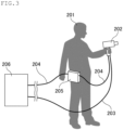
- FIG. 3 Another example (an example in which the portion including the objective lens is in a portable form) of the OCT device of the disclosure is shown in FIG. 3 .
- the OCT device of the disclosure is not limited thereto.
- a user 201 carries a probe 202 of the OCT device in one hand and carries a galvanometer mirror driver 205 for driving the galvanometer mirror in the probe 202 at the waist.
- the probe 202 is connected to a housing 206 of the OCT device via an optical fiber 203.
- the galvanometer mirror driver 205 is connected to the probe 202 and the housing 206 via respective electric wires 204.
- the housing 206 contains a light source, a detector, a DAQ system, an arithmetic logic unit, and the like.
- the OCT device of the disclosure is preferably configured such that the area in the plane direction to be imaged at an optical resolution of 10 um or longer per tomographic imaging session using the following light source is 0.1 to 14 mm in length and 0.1 to 14 mm in width. This enables high-precision tomographic imaging over a wide area at one time (even with a different light source).
- the OCT device of the disclosure may be used to perform optical coherence tomographic imaging of a sample.
- the disclosure also relates to an optical coherence tomography method using the aforementioned OCT device of the disclosure.
- the optical coherence tomography method of the disclosure causes no difference in environmental conditions between the sample light path and the reference light path even in the case where a user carries the portion including the objective lens (e.g., the probe) to perform tomographic imaging. This results in a small shift in a tomographic image obtained.
- This method also enables tomographic imaging over a wide area at one time.
- the OCT device and the optical coherence tomography method of the disclosure can be suitably applied to the whole range of optical coherence tomography regardless of the fields. As described above, they are less likely to cause a shift in a tomographic image even in the case where a portion of the OCT device is in a portable form and they enable tomographic imaging over a wide area at one time. Accordingly, the device and the method can be suitably used especially in the industrial field.
- a fluororesin sheet having a thickness of 7.8 mm, a length of 25 mm, and a width of 25 mm was prepared, which was a stack of a 3.1-mm-thick polytetrafluoroethylene (PTFE) layer, a 0.4-mm-thick tetrafluoroethylene-hexafluoropropylene copolymer (FEP) layer, and a 4.3-mm-thick tetrafluoroethylene-perfluoro(alkyl vinyl ether) copolymer (PFA) layer in the stated order.
- PTFE polytetrafluoroethylene
- FEP 0.4-mm-thick tetrafluoroethylene-hexafluoropropylene copolymer
- PFA 4.3-mm-thick tetrafluoroethylene-perfluoro(alkyl vinyl ether) copolymer
- the details of the OCT device and imaging conditions used are as follows.
- OCT imaging was performed as in Example 1 except that the objective lens was changed to an achromatic lens (trade name: AC254-050-C, available from Thorlabs, Inc., effective wavelength range: 1050 to 1700 nm, effective focal length: 50 mm), which is not an F ⁇ lens.
- the resulting tomographic image (length 8 mm ⁇ width 8 mm) is shown in FIG. 5 .
- the whole tomographic image is clear and uniform.
- the image excluding the portion enclosed by dotted lines includes significant noise and has a narrow effective visual field (shows a failure in tomographic imaging over a wide area).
- An OCT device having the structure shown in FIG. 1 was used and the optical fiber of the sample arm alone was heated to 40°C using a dryer. Then, OCT imaging was performed in the cross-sectional direction of a fluororesin tube having an outer diameter of 12 mm and an inner diameter of 8 mm. The resulting tomographic image is shown in FIG. 6 .
- the details of the OCT device and imaging conditions used are as follows.
- OCT imaging was performed as in Comparative Example 2 except that the optical fiber of the sample arm was not heated.
- the resulting tomographic image is shown in FIG. 7 .
- FIG. 6 obtained under a temperature difference between the arms, the tomographic image of the tube is drifted upwards in the depth direction by 2 mm or greater compared to FIG. 7 and the portion corresponding to the tube surface layer protrudes from the image. Further, FIG. 6 includes an artifact (an inverted arch at the upper portion of the image), which is reflection noise.
Landscapes
- Physics & Mathematics (AREA)
- General Physics & Mathematics (AREA)
- Health & Medical Sciences (AREA)
- General Health & Medical Sciences (AREA)
- Nuclear Medicine, Radiotherapy & Molecular Imaging (AREA)
- Radiology & Medical Imaging (AREA)
- Life Sciences & Earth Sciences (AREA)
- Engineering & Computer Science (AREA)
- Pathology (AREA)
- Immunology (AREA)
- Chemical & Material Sciences (AREA)
- Biochemistry (AREA)
- Analytical Chemistry (AREA)
- Biomedical Technology (AREA)
- Medical Informatics (AREA)
- Molecular Biology (AREA)
- Surgery (AREA)
- Animal Behavior & Ethology (AREA)
- Public Health (AREA)
- Veterinary Medicine (AREA)
- Heart & Thoracic Surgery (AREA)
- Ophthalmology & Optometry (AREA)
- Biophysics (AREA)
- Optics & Photonics (AREA)
- Automation & Control Theory (AREA)
- Investigating Or Analysing Materials By Optical Means (AREA)
Abstract
Description
- The disclosure relates to optical coherence tomography devices and optical coherence tomography methods.
- Optical coherence tomography (OCT) is mainly used for tomographic imaging of biological organs such as eyeballs in the medical field.
- Typical optical coherence tomography devices are configured to split the light from a light source by, for example, a beam splitter, apply the resulting light beams separately to a sample and a reference mirror and obtain reflected light beams passed through respective optical paths, obtain the interference between these reflected light beams, and utilize the interference for tomographic imaging (for example, see Patent Literature 1).
- Patent Literature 1:
JP 2011-104127 A - The disclosure aims to provide an optical coherence tomography device that is less likely to cause a shift in a tomographic image even in a portable form and that performs tomographic imaging over a wide area at one time, and an optical coherence tomography method using the optical coherence tomography device.
- The disclosure relates to an optical coherence tomography device including an objective lens configured to focus light from a light source onto a sample, the optical coherence tomography device being configured to perform tomographic imaging of the sample based on interference between sample light, which is reflected light from the sample, and reference light, which is reflected light from a reference surface provided between the objective lens and the sample, the sample light and the reference light each being to pass through the objective lens, the objective lens being an Fθ lens.
- The optical coherence tomography device is preferably configured to perform the tomographic imaging with a distance between the reference surface and the sample being 0 to 3 cm.
- The reference surface is preferably a flat surface of a reference item containing at least one selected from the group consisting of MgF2, CaF2, quartz, and sapphire.
- The sample light and the reference light are each preferably generated from the light emitted from the light source and passed through the objective lens.
- The interference is preferably Fizeau interference.
- The optical coherence tomography device preferably further includes a circulator configured to: output the light from the light source toward the objective lens; and output the sample light and the reference light passed through the objective lens toward a detector configured to detect the sample light and the reference light.
- Preferably, the optical coherence tomography device further includes a coupler configured to split the light emitted from the light source into
split light 1 to be used for generating the sample light and the reference light and splitlight 2 to be used for removing a DC component of an interference signal, wherein thesplit light 1 and thesplit light 2 have an intensity ratio of 90:10 to 99:1. - Preferably, the optical coherence tomography device is configured to perform the tomographic imaging while a user carries a portion comprising the objective lens.
- Preferably, the portion including the objective lens to be carried and a portion not to be carried are connected via an optical fiber, and the light emitted from the light source as well as the sample light and the reference light are transmitted through the optical fiber.
- Preferably, an optical coherence tomographic image obtained has a shift of 100 um or smaller when the optical fiber has a length of 3 m or longer and an atmosphere around the portion including the objective lens to be carried and an atmosphere around the portion not to be carried have a temperature difference of 1°C or greater.
- The disclosure also relates to an optical coherence tomography method including using any of the aforementioned optical coherence tomography devices.
- The disclosure can provide an optical coherence tomography device that is less likely to cause a shift in a tomographic image even in a portable form and that performs tomographic imaging over a wide area at one time, and an optical coherence tomography method using the device.
-
-
FIG. 1 is a schematic diagram of an example of a conventional optical coherence tomography (OCT) device. -
FIG. 2 is a schematic diagram of an example of the OCT device of the disclosure. -
FIG. 3 is a schematic diagram of another example of the OCT device of the disclosure. -
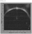
FIG. 4 is an OCT image obtained in Example 1. -
FIG. 5 is an OCT image obtained in Comparative Example 1. -
FIG. 6 is an OCT image obtained in Comparative Example 2. -
FIG. 7 is an OCT image obtained in Reference Example 1. - In the medical field, an optical coherence tomography (OCT) device including a Michelson interferometer as shown in
FIG. 1 is commonly used. AnOCT device 10 ofFIG. 1 is configured such that the light output from alight source 11 is split by acoupler 12 into reference light, which is to pass through an optical path including acirculator 13 and areference mirror 14, and sample light, which is to pass through an optical path including acirculator 15 and asample 16. The reference light and the sample light are recombined by acoupler 17 and an interference signal is detected by aphotodetector 18. - In the medical field, a probe including the sample light path and an OCT device body (housing) including the reference light path are placed close to each other and are used in the same room in common cases.
- In contrast, fields such as the industrial field may require imaging of an object placed far from the OCT device body (housing), e.g., in the open air, while a probe is carried. In this case, the Michelson OCT device shown in
FIG. 1 , in which the sample light and the reference light pass through the different optical paths, is likely to suffer difference in environmental conditions (e.g., temperature) under which the sample light path (probe) and the reference light path (body) are placed. This causes a difference between the optical path lengths, resulting in a great shift (drift) in a tomographic image obtained. - Further, OCT devices used in the medical field have a priority to provide a high-precision tomographic image of a very narrow area, such as an eyeball, and are difficult to apply to fields where tomographic imaging over a wide area at one time is required.
- The disclosers performed studies to find that allowing both the sample light and the reference light to pass through the objective lens and using an Fθ (F-theta) lens as the objective lens can solve the above issues, completing the OCT device of the disclosure.
- Hereinafter, the disclosure is described in detail.
- The disclosure relates to an optical coherence tomography (OCT) device including an objective lens configured to focus light from a light source onto a sample, the optical coherence tomography device being configured to perform tomographic imaging of the sample based on interference between sample light, which is reflected light from the sample, and reference light, which is reflected light from a reference surface, provided between the objective lens and the sample, the sample light and the reference light each being to pass through the objective lens, the objective lens being an Fθ lens.
- The OCT device of the disclosure is configured such that the sample light, which is reflected light from a sample to be imaged, and the reference light, which is reflected light from a reference surface, both pass through the objective lens. This structure can prevent difference in environmental conditions between the sample light path and the reference light path even when a portion including the objective lens (e.g., a probe) is in a portable form, resulting in a small shift in a tomographic image obtained.
- The sample light and the reference light are to be incident on the objective lens through the surface close to the sample and are to be emitted therefrom through the surface close to the light source.
- The sample light and the reference light are generated from the light from the light source. The light from the light source passes through the objective lens of the OCT device of the disclosure and focuses on the sample. The light reflected on the sample serves as the sample light. Part of the light from the light source is reflected on a reference surface provided between the objective lens and the sample, serving as the reference light.
- The sample light and the reference light are each preferably generated from the light emitted from the light source and passed through the objective lens. In comparison with conventional Michelson OCT devices in which the light is split before passing through the objective lens to separately generate the sample light and the reference light, the above structure of the disclosure can reduce the difference in environmental conditions between the sample light path and the reference light path and can more greatly reduce the shift in a tomographic image obtained.
- The objective lens of the OCT device of the disclosure is an Fθ lens. This structure enables tomographic imaging over a wide area at one time.
- The Fθ lens is a lens that emits the incident light to the position apart from the optical axis by Fθ on the focal plane perpendicular to the optical axis, where f represents the focal length of the lens and θ represents the angle between the incident light and the optical axis of the lens.
- The Fθ lens may be a telecentric Fθ lens or may be a non-telecentric Fθ lens.
- The telecentric Fθ lens is an Fθ lens designed such that the main light beam is to be parallel to the optical axis of the lens, and is preferred in that it can provide a high-precision tomographic image even when the distance between the lens and a sample varies.
- In the OCT device of the disclosure, the light beams passed through the objective lens are not necessarily incident on the sample in a telecentric manner. Still, in order to provide a tomographic image with a higher precision, the objective lens is preferably placed so that the light beams are incident on the sample in a maximally telecentric manner.
- The reference surface is preferably provided between the objective lens and the sample perpendicularly to the optical axis of the objective lens.
- The reference surface is any surface that reflects at least part of the light from the light source. In order to easily achieve a structure in which the sample light and the reference light pass through a common optical path, the reference surface is preferably a surface that transmits part of the light from the light source and reflects another part thereof. In this embodiment, the light transmitted through the reference surface focuses on the sample to generate the sample light, while the light reflected on the reference surface serves as the reference light.
- The reference surface is preferably a flat surface of a reference item, more preferably the surface close to the sample of the reference item.
- The reference item is preferably one that transmits part of the light from the light source and reflects another part thereof.
- The material of the reference item may be a crystalline material, preferably a crystal that can be used for an optical window. Specific examples thereof include crystals of MgF2, quartz (SiO2), sapphire (Al2O3), CaF2, BaF2, LiF, and ZnSe. Owing to their excellent chemical resistance, preferred among these is at least one selected from the group consisting of MgF2, CaF2, quartz, and sapphire.
- In a preferred embodiment, the reference surface is a flat surface of a reference item containing at least one selected from the group consisting of MgF2, CaF2, quartz, and sapphire.
- The reference item is preferably one without any coating (e.g., coating for reflection control).
- The reference item may have any shape including a flat surface, such as a plate shape, a cylindrical shape, or a prism shape, preferably a cylindrical shape. The cylindrical shape is not necessarily a perfectly circular cylindrical shape. In the case of a reference item including a different flat surface in addition to the reference surface, the reference surface and the different flat surface are not necessarily parallel to each other.
- The reference item has a thickness (thickness in the optical axis direction) of preferably 1 to 50 mm, more preferably 10 to 30 mm.
- In the case where the reference item has a non-uniform thickness, the thickness at the thinnest portion and the thickness at the thickest portion are each preferably within the above range.
- The reference item preferably satisfies the following relation (1):

- The optical thickness is the product of the refractive index of the reference item and the actual (geometric) thickness.
- The measurable distance is expressed by the following relation (2):

- Using a reference item satisfying the relation (1) can prevent appearance of a signal based on back reflection on the back bottom surface (the surface opposite to the reference surface) of the reference item in a tomographic image (within the area corresponding to a depth of not smaller than 0 but smaller than Zmax), which can provide a tomographic image with a higher precision.
- The reference item more preferably satisfies the following relation (3):

- The working distance refers to the distance between the forefront surface close to the sample of the objective lens and the sample, with the lens being in focus.
- Using a reference item satisfying the relation (3) can reduce the intensity of a ghost image based on back reflection on the back bottom surface (the surface opposite to the reference surface) of the reference item, which can provide a tomographic image with a higher precision.
- In order to more reduce the intensity of a ghost image based on back reflection, the thickness of the reference item is preferably as thick as possible within the range satisfying the relation (3). Also, preferably, the back bottom surface of the reference item is tilted relative to the reference surface.
- The aforementioned effect is particularly significant in the case of placing an anti-aliasing filter (low-pass filter) to be described later.
- The reference item particularly preferably satisfies the following relation (4):

- In the formula, m is preferably an integer of 1 or greater and 20 or smaller, more preferably an integer of 1 or greater and 10 or smaller.
- Using a reference item satisfying the relation (4) allows a signal based on back reflection on the back bottom surface (the surface opposite to the reference surface) of the reference item to overlap an edge of a tomographic image (the position corresponding to a depth of 0 or Zmax) and to less affect the tomographic image, which can provide a tomographic image with a much higher precision.
- The OCT device of the disclosure may include the reference surface (reference item).
- The OCT device of the disclosure is preferably configured to perform the tomographic imaging with the distance between the reference surface and the sample being 0 to 3 cm. Placing the reference surface and the sample close to each other in this way is preferred because this arrangement can lead to a short working distance, small noise, and a high resolution, as well as focusing at a deeper portion of the sample, resulting in a clearer tomographic image including a deeper portion. The OCT device of the disclosure includes an Fθ lens as the objective lens and can therefore perform high-precision tomographic imaging even when the reference surface and the sample are close to each other as described above.
- Tomographic imaging may of course be performed with the distance between the reference surface and the sample being greater than the above.
- The light source may be a low coherence light source, and is preferably a frequency-scanning light source configured to perform scanning while changing the frequency (wavelength) over time.
- Examples of the frequency-scanning light source used include a wavelength-swept laser utilizing a wavelength-swept filter (e.g., driving with a polygonal mirror, driving with a galvanometer mirror), an FDML laser, a MEMS wavelength-swept light source (e.g., MEMS VCSEL, external cavity MEMS Fabry-Pérot laser), and an SGDBR laser.
- Examples of the light beam output from the light source include visible light and infrared light. Near infrared light (NIR) is preferred. The light beam used is preferably a light beam having a wavelength of 800 to 2000 nm. In particular, from the viewpoint of stability of the light source and reliability of the sensor, more preferred is a light beam having a central wavelength of 940 ± 50 nm, 1100 ± 50 nm, 1310 ± 50 nm, 1550 ± 100 nm, or 1750 ± 100 nm.
- The OCT device of the disclosure may include the light source.
- The OCT device of the disclosure performs tomographic imaging of the sample based on the interference between the sample light and the reference light. The interference may be any one that allows both the sample light and the reference light to theoretically pass through the objective lens, preferably Fizeau interference or Mirau interference, more preferably Fizeau interference.
- Examples of OCT types to be used in the OCT device of the disclosure include time domain OCT (TD-OCT) and Fourier domain OCT (FD-OCT). Examples of the FD-OCT include spectral domain OCT (SD-OCT) and swept source OCT (SS-OCT). Owing to its high sensitivity and deep measurable depth, preferred among these is SS-OCT.
- The OCT device of the disclosure preferably further includes a collimator configured to convert the light from the light source into parallel light. The collimator is preferably provided on the optical paths between the light source and the objective lens.
- The OCT device of the disclosure preferably further includes a scanning mirror configured to scan the light emitted from the light source and focused on the sample. The scanning mirror is preferably provided on the optical path between the light source and the objective lens, and is more preferably provided on the optical path between the collimator and the objective lens.
- Examples of the scanning mirror include a galvanometer mirror, a polygonal mirror, and a MEMS mirror. Preferred among these is a galvanometer mirror, more preferred is a single-axis or two-axis galvanometer mirror, still more preferred is a two-axis galvanometer mirror.
- The OCT device of the disclosure preferably further includes a driver for driving the scanning mirror.
- The OCT device of the disclosure preferably further includes a circulator configured to output the light from the light source toward the objective lens and output the sample light and the reference light passed through the objective lens toward a detector configured to detect the sample light and the reference light. In this embodiment, the sample light and the reference light can be transmitted by a single circulator. This configuration enables a smaller device and a lower cost than in the case of providing circulators separately for the sample light and the reference light as shown in
FIG. 1 . - The circulator preferably has three or more ports, more preferably has three ports.
- The circulator is preferably provided on the optical path between the light source and the objective lens, more preferably provided on the optical path between the light source and the collimator.
- In the case of a three-port circulator, the light from the light source is input to a first port close to the light source and output from a second port close to the objective lens. The sample light and the reference light passed through the objective lens are input to the second port and output from a third port close to the detector.
- The OCT device of the disclosure preferably further includes a detector (also referred to as a detector (1)) configured to detect the sample light and the reference light. The detector (1) is preferably configured to detect an interference signal generated by the sample light and the reference light.
- The detector (1) is preferably a differential photodetector. The detector (1) may have a function to amplify a signal. Alternatively, an amplifier may be provided separately.
- The OCT device of the disclosure preferably further includes a coupler (also referred to as a coupler (1)) configured to split the light from the light source into
split light 1 to be used for generating the sample light and the reference light and split light 2 to be used for removing a DC component of an interference signal. The coupler (1) is preferably provided on the optical path between the light source and the objective lens, more preferably provided on the optical path between the light source and the circulator. - The coupler (1), when provided, allows the
split light 1 and thesplit light 2 to have an intensity ratio of preferably 90:10 to 99:1, more preferably 92:8 to 98:2. Light splitting with this intensity ratio enables effective removal of a DC component from an interference signal. - The OCT device of the disclosure preferably further includes a detector (also referred to as a detector (2)) configured to detect the
split light 2. The detector (2) may be the same detector as the aforementioned detector (1) or may be a different detector. - The OCT device of the disclosure preferably further includes an attenuator configured to attenuate the
split light 2. The attenuator is preferably a variable optical attenuator (VOA). The attenuator is preferably provided on the optical path between the coupler (1) and the detector (2) configured to detect thesplit light 2. - The OCT device of the disclosure preferably further includes a data acquisition (DAQ) system configured to acquire an interference signal generated by the sample light and the reference light. The DAQ system preferably includes an A/D converter. The DAQ system is preferably configured to convert the acquired interference signal into digital data.
- The OCT device of the disclosure preferably further includes an anti-aliasing filter (also referred to as a low-pass filter) configured to attenuate unnecessary frequency components exceeding the measurable distance (Zmax). The anti-aliasing filter is preferably provided on the optical path between the detector (1) and the DAQ system described above.
- The OCT device of the disclosure preferably further includes an arithmetic logic unit configured to generate an optical coherence tomographic image based on the interference signal generated by the sample light and the reference light. The arithmetic logic unit is configured to image the interference signal according to the properties such as the intensity to generate an optical coherence tomographic image.
- The OCT device of the disclosure preferably further includes a display configured to display an optical coherence tomographic image obtained. The display may be of a stationary type or a portable type. A portable one is preferred because the image can be checked at the site where the image is obtained. The connection with the arithmetic logic unit may be wired or wireless. One display may be provided or multiple displays may be provided.
-
FIG. 2 shows an example of the OCT device of the disclosure. The OCT device of the disclosure is not limited thereto. - An
OCT device 100 inFIG. 2 is configured such that a frequency-scanning light source 101 outputs the light to be used in OCT. The frequency-scanning light source 101 outputs a trigger signal at every start of frequency scanning. A Mach-Zehnder interferometer detects the light and outputs a K-clock signal for equal frequency interval sampling. - The light output from the frequency-
scanning light source 101 is split by acoupler 102 into split light 1 to be used for generating sample light and reference light and splitlight 2 for removing a DC component of an interference signal at an intensity ratio of 95:5. Thesplit light 1 is input to aport 1 of acirculator 103 and output from aport 2, and is transferred to aprobe 104 through an optical fiber having a length of several meters. - In the
probe 104, thesplit light 1 is converted by acollimator 105 into parallel light, which is then reflected on agalvanometer mirror 106 and incident on anobjective lens 107, which is an Fθ lens. Thegalvanometer mirror 106 is driven by agalvanometer mirror driver 111 and scans the parallel light in the X-Y direction perpendicular to the optical axis. The parallel light incident on theobjective lens 107 passes through areference item 108 and focuses on asample 110 to be imaged, and is then reflected on the surface of the sample and incident on theobjective lens 107 as sample light. Part of the parallel light incident on theobjective lens 107 is reflected on areference surface 109 of thereference item 108 and then incident on theobjective lens 107 as reference light. - The sample light and the reference light incident on the
objective lens 107 pass through thegalvanometer mirror 106 and thecollimator 105, and are then input to aport 2 of thecirculator 103 via the optical fiber, output from aport 3, and input to adifferential photodetector amplifier 113. Thedifferential photodetector amplifier 113 detects and amplifies the interference signal based on the interference between the sample light and the reference light. - The
split light 2 generated by thecoupler 102 is attenuated by a variableoptical attenuator 112 and then input to thedifferential photodetector amplifier 113. Thedifferential photodetector amplifier 113 utilizes the signal of thesplit light 2 to remove the DC component in the interference signal. - The amplified interference signal from which the DC component is removed by the
differential photodetector amplifier 113 is collected and converted into digital data by the DAQ system (A/D converter) of aPC 114. Collection of the interference signal is initiated by a trigger signal emitted from the frequency-scanning light source 101 and synchronizes with the K-clock signal. - Between the
differential photodetector amplifier 113 and the DAQ system is provided an anti-aliasing filter (not shown) that attenuates unnecessary frequency components exceeding the measurable distance (Zmax). - The arithmetic logic unit of the
PC 114 generates an optical coherence tomographic image of thesample 110 based on the interference signal converted by the DAQ system and displays it on amobile display 115. - The OCT device of the disclosure is preferably configured to enable the tomographic imaging while a user carries a portion including the objective lens. Even in such a case where the portion including the objective lens is in a portable form, the OCT device of the disclosure can prevent difference in environmental conditions between the sample light path and the reference light path, resulting in a small shift in a tomographic image obtained.
- The portion including the objective lens preferably further includes the reference surface (or the reference item), the collimator, and the scanning mirror.
- The portion including the objective lens is preferably a probe of the OCT device.
- The OCT device of the disclosure is preferably configured to enable the tomographic imaging while a user holds the portion including the objective lens in hand(s), more preferably to enable the tomographic imaging while a user holds the portion including the objective lens in one hand.
- The OCT device of the disclosure may further include a portion that may be carried by a user during tomographic imaging in addition to the portion including the objective lens. Examples of this carriable portion include a driver for driving the scanning mirror and the display.
- The OCT device of the disclosure is preferably such that the portion including the objective lens to be carried and a portion not to be carried are connected via an optical fiber and that the light from the light source as well as the sample light and the reference light are transferred through the optical fiber. In this embodiment, an object to be imaged, which is placed far from the portion not to be carried, can be subjected to tomographic imaging by adjusting the length of the optical fiber so that the portion including the objective lens is placed near the object to be imaged. Since the light from the light source as well as the sample light and the reference light are transferred through the optical fiber, no difference in environmental conditions occurs between the sample light path and the reference light path even when the optical fiber is long, resulting in a small shift in a tomographic image obtained. Further, since the device is wired with the optical fiber, an object to be imaged placed far from the portion not to be carried can also be subjected to high-resolution OCT measurement.
- The optical fiber may have any length in accordance with the place of an object to be imaged. The length may be 1 m or longer, preferably 3 m or longer, more preferably 5 m or longer, still more preferably 10 m or longer, while it may be 100 m or shorter, or may be 50 m or shorter.
- For example, the portion not to be carried preferably includes the light source, the circulator, the detector, the DAQ system, the arithmetic logic unit, and the like.
- The portion not to be carried is preferably an OCT device body (housing).
- In the case where a different carriable portion is present in addition to the portion including the objective lens, this different portion and the portion including the objective lens or the portion not to be carried may be connected not necessarily via an optical fiber. They may be connected via an electric wire.
- The OCT device of the disclosure is preferably such that an optical coherence tomographic image obtained has a shift of 100 um or smaller when the optical fiber has a length of 3 m or longer and the atmosphere around the portion including the objective lens to be carried and the atmosphere around the portion not to be carried have a temperature difference of 1°C or greater.
- In fields such as the industrial field, an object to be imaged may be placed far from the OCT device body (housing), in the open air, or in a high- or low-temperature facility. In these cases, a great difference in environmental conditions (temperature) occurs between the probe and the OCT device body. Thus, an OCT device including the sample light path on the probe end and the reference light path on the body end provides a tomographic image with a great shift due to the difference in environmental conditions between the sample light path and the reference light path. In contrast, even in the above case, the OCT device of the disclosure causes no difference in environmental conditions between the sample light path and the reference light path, resulting in a small shift in a tomographic image obtained.
- In the above embodiment, the length of the optical fiber is preferably 3 m or longer, more preferably 5 m or longer, still more preferably 10 m or longer, while it may be 100 m or shorter, or may be 50 m or shorter.
- In the above embodiment, the temperature difference between the atmospheres is 1°C or greater, more preferably 5°C or greater, still more preferably 10°C or greater. The temperature difference is preferably 50°C or smaller.
- The shift of the optical coherence tomographic image is preferably 100 um or shorter, more preferably 50 um or shorter, particularly preferably 30 um or shorter.
- The shift (ΔZ) is defined by the following equation (A):

- ΔZ refers to the shift in the optical distance.
- In the case where the optical fiber material is quartz glass, the optical wavelength is 1.3 um, and the temperature is around room temperature, dn/dT is about 1.9 × 10⁻⁵ (1/°C).
- In the case of an OCT device including the sample light path on the probe end and the reference light path on the body end, the temperature difference between the atmosphere around the portion including the objective lens to be carried and the atmosphere around the portion not to be carried is almost directly reflected in the temperature difference Δt between the optical paths. This causes a great shift ΔZ in a tomographic image obtained. In contrast, in the case of the OCT device of the disclosure, the temperature difference Δt between the optical paths is significantly small even when the temperature difference is large between the atmosphere around the portion including the objective lens to be carried and the atmosphere around the portion not to be carried. This results in a significantly small shift ΔZ.
- Another example (an example in which the portion including the objective lens is in a portable form) of the OCT device of the disclosure is shown in
FIG. 3 . The OCT device of the disclosure is not limited thereto. - In
FIG. 3 , auser 201 carries aprobe 202 of the OCT device in one hand and carries agalvanometer mirror driver 205 for driving the galvanometer mirror in theprobe 202 at the waist. Theprobe 202 is connected to ahousing 206 of the OCT device via anoptical fiber 203. Thegalvanometer mirror driver 205 is connected to theprobe 202 and thehousing 206 via respectiveelectric wires 204. - The
housing 206 contains a light source, a detector, a DAQ system, an arithmetic logic unit, and the like. - The OCT device of the disclosure is preferably configured such that the area in the plane direction to be imaged at an optical resolution of 10 um or longer per tomographic imaging session using the following light source is 0.1 to 14 mm in length and 0.1 to 14 mm in width. This enables high-precision tomographic imaging over a wide area at one time (even with a different light source).
- High speed swept source available from Axsun Technologies (central wavelength: 1310 nm, sweep width: 100 nm, A-scan rate: 50 kHz, output: 25 mW, coherence length: 12 mm)
- The OCT device of the disclosure may be used to perform optical coherence tomographic imaging of a sample. The disclosure also relates to an optical coherence tomography method using the aforementioned OCT device of the disclosure.
- The optical coherence tomography method of the disclosure causes no difference in environmental conditions between the sample light path and the reference light path even in the case where a user carries the portion including the objective lens (e.g., the probe) to perform tomographic imaging. This results in a small shift in a tomographic image obtained. This method also enables tomographic imaging over a wide area at one time.
- The OCT device and the optical coherence tomography method of the disclosure can be suitably applied to the whole range of optical coherence tomography regardless of the fields. As described above, they are less likely to cause a shift in a tomographic image even in the case where a portion of the OCT device is in a portable form and they enable tomographic imaging over a wide area at one time. Accordingly, the device and the method can be suitably used especially in the industrial field.
- The disclosure is more specifically described below with reference to, but not limited to, examples.
- A fluororesin sheet having a thickness of 7.8 mm, a length of 25 mm, and a width of 25 mm was prepared, which was a stack of a 3.1-mm-thick polytetrafluoroethylene (PTFE) layer, a 0.4-mm-thick tetrafluoroethylene-hexafluoropropylene copolymer (FEP) layer, and a 4.3-mm-thick tetrafluoroethylene-perfluoro(alkyl vinyl ether) copolymer (PFA) layer in the stated order. Using an OCT device having the structure shown in
FIG. 2 , OCT imaging of the fluororesin sheet was performed from the PFA layer end. The resulting tomographic image (length 8 mm × width 8 mm) is shown inFIG. 4 . - The details of the OCT device and imaging conditions used are as follows.
- OCT swept laser light source: central wavelength 1310 nm,
sweep width 100 nm, A-scan rate 50 kHz, output 25 mW,coherence length 12 mm - Objective lens: Fθ lens (trade name: LSM04, available from Thorlabs, Inc.), effective wavelength range (1250 to 1380 nm), effective focal length (54 mm)
- Reference item: made of quartz glass, cylindrical shape, diameter 20 mmϕ, length 20 mm
- Optical fiber: made of quartz glass, length 10 m
- Imaging temperature: 26°C
- Distance between reference surface and sample: 0 cm
- Other imaging conditions:
brightness 100, contrast ratio 30 - OCT imaging was performed as in Example 1 except that the objective lens was changed to an achromatic lens (trade name: AC254-050-C, available from Thorlabs, Inc., effective wavelength range: 1050 to 1700 nm, effective focal length: 50 mm), which is not an Fθ lens. The resulting tomographic image (length 8 mm × width 8 mm) is shown in
FIG. 5 . - In
FIG. 4 , the whole tomographic image is clear and uniform. InFIG. 5 , the image excluding the portion enclosed by dotted lines includes significant noise and has a narrow effective visual field (shows a failure in tomographic imaging over a wide area). - An OCT device having the structure shown in
FIG. 1 was used and the optical fiber of the sample arm alone was heated to 40°C using a dryer. Then, OCT imaging was performed in the cross-sectional direction of a fluororesin tube having an outer diameter of 12 mm and an inner diameter of 8 mm. The resulting tomographic image is shown inFIG. 6 . - The details of the OCT device and imaging conditions used are as follows.
- OCT swept laser light source: central wavelength 1310 nm,
sweep width 100 nm, A-scan rate 50 kHz, output 25 mW,coherence length 12 mm - Objective lens: Fθ lens (trade name: LSM03, available from Thorlabs, Inc.), effective wavelength range (1250 to 1380 nm), effective focal length (36 mm)
- Optical fibers (sample arm, reference arm): made of quartz glass, length 4 m
- Imaging temperature: 26°C
- Other imaging conditions:
brightness 100, contrast ratio 30 - OCT imaging was performed as in Comparative Example 2 except that the optical fiber of the sample arm was not heated. The resulting tomographic image is shown in
FIG. 7 . - In
FIG. 6 obtained under a temperature difference between the arms, the tomographic image of the tube is drifted upwards in the depth direction by 2 mm or greater compared toFIG. 7 and the portion corresponding to the tube surface layer protrudes from the image. Further,FIG. 6 includes an artifact (an inverted arch at the upper portion of the image), which is reflection noise. -
- 10:
- OCT device
- 11:
- light source
- 12, 17:
- coupler
- 13, 15:
- circulator
- 14:
- reference mirror
- 16:
- sample
- 18:
- photodetector
- 100:
- OCT device
- 101:
- frequency-scanning light source
- 102:
- coupler
- 103:
- circulator
- 104:
- probe
- 105:
- collimator
- 106:
- galvanometer mirror
- 107:
- objective lens
- 108:
- reference item
- 109:
- reference surface
- 110:
- sample
- 111:
- galvanometer mirror driver
- 112:
- variable optical attenuator
- 113:
- differential photodetector amplifier
- 114:
- PC
- 115:
- mobile display
- 201:
- user
- 202:
- probe
- 203:
- optical fiber
- 204:
- electric wire
- 205:
- galvanometer mirror driver
- 206:
- housing
Claims (11)
- An optical coherence tomography device comprising an objective lens configured to focus light from a light source onto a sample,the optical coherence tomography device being configured to perform tomographic imaging of the sample based on interference between sample light, which is reflected light from the sample, and reference light, which is reflected light from a reference surface provided between the objective lens and the sample,the sample light and the reference light each being to pass through the objective lens,the objective lens being an Fθ lens.
- The optical coherence tomography device according to claim 1,
wherein the optical coherence tomography device is configured to perform the tomographic imaging with a distance between the reference surface and the sample being 0 to 3 cm. - The optical coherence tomography device according to claim 1 or 2,
wherein the reference surface is a flat surface of a reference item containing at least one selected from the group consisting of MgF2, CaF2, quartz, and sapphire. - The optical coherence tomography device according to any one of claims 1 to 3,
wherein the sample light and the reference light are each generated from the light emitted from the light source and passed through the objective lens. - The optical coherence tomography device according to any one of claims 1 to 4,
wherein the interference is Fizeau interference. - The optical coherence tomography device according to any one of claims 1 to 5, further comprising a circulator configured to:output the light from the light source toward the objective lens; andoutput the sample light and the reference light passed through the objective lens toward a detector configured to detect the sample light and the reference light.
- The optical coherence tomography device according to any one of claims 1 to 6, further comprising a coupler configured to split the light emitted from the light source into split light 1 to be used for generating the sample light and the reference light and split light 2 to be used for removing a DC component of an interference signal,
wherein the split light 1 and the split light 2 have an intensity ratio of 90:10 to 99:1. - The optical coherence tomography device according to any one of claims 1 to 7,
wherein the optical coherence tomography device is configured to perform the tomographic imaging while a user carries a portion comprising the objective lens. - The optical coherence tomography device according to claim 8,wherein the portion comprising the objective lens to be carried and a portion not to be carried are connected via an optical fiber, andthe light emitted from the light source as well as the sample light and the reference light are transmitted through the optical fiber.
- The optical coherence tomography device according to claim 9,
wherein an optical coherence tomographic image obtained has a shift of 100 um or smaller when the optical fiber has a length of 3 m or longer and an atmosphere around the portion comprising the objective lens to be carried and an atmosphere around the portion not to be carried have a temperature difference of 1°C or greater. - An optical coherence tomography method comprising using the optical coherence tomography device according to any one of claims 1 to 10.
Applications Claiming Priority (2)
| Application Number | Priority Date | Filing Date | Title |
|---|---|---|---|
| JP2020158782 | 2020-09-23 | ||
| PCT/JP2021/034580 WO2022065305A1 (en) | 2020-09-23 | 2021-09-21 | Optical coherence tomography device and optical coherence tomography method |
Publications (2)
| Publication Number | Publication Date |
|---|---|
| EP4220127A1 true EP4220127A1 (en) | 2023-08-02 |
| EP4220127A4 EP4220127A4 (en) | 2025-01-15 |
Family
ID=80845476
Family Applications (1)
| Application Number | Title | Priority Date | Filing Date |
|---|---|---|---|
| EP21872434.2A Pending EP4220127A4 (en) | 2020-09-23 | 2021-09-21 | OPTICAL COHERENCE TOMOGRAPHY DEVICE AND OPTICAL COHERENCE TOMOGRAPHY METHOD |
Country Status (7)
| Country | Link |
|---|---|
| US (1) | US12392600B2 (en) |
| EP (1) | EP4220127A4 (en) |
| JP (2) | JP7128430B2 (en) |
| KR (1) | KR102902157B1 (en) |
| CN (1) | CN116324380A (en) |
| TW (1) | TWI833116B (en) |
| WO (1) | WO2022065305A1 (en) |
Families Citing this family (3)
| Publication number | Priority date | Publication date | Assignee | Title |
|---|---|---|---|---|
| US20240032796A1 (en) * | 2022-07-29 | 2024-02-01 | KineoLabs | Compact all free-space line-field swept source OCT system |
| CN116735153A (en) * | 2023-07-12 | 2023-09-12 | 中国科学院长春光学精密机械与物理研究所 | Large-diameter sparse aperture telescope mirror splicing detection device and detection method |
| JP7832523B2 (en) * | 2024-08-21 | 2026-03-18 | ダイキン工業株式会社 | Signal processing method, information processing device, optical coherence tomography device, and program |
Family Cites Families (26)
| Publication number | Priority date | Publication date | Assignee | Title |
|---|---|---|---|---|
| JP2000258144A (en) * | 1999-03-05 | 2000-09-22 | Horiba Ltd | Flatness and thickness measurement device for wafer |
| JP2001046321A (en) | 1999-08-09 | 2001-02-20 | Asahi Optical Co Ltd | Endoscope device |
| JP2001051225A (en) | 1999-08-10 | 2001-02-23 | Asahi Optical Co Ltd | Polygon mirror, scanning optical system, and endoscope device |
| JP3869257B2 (en) * | 2001-12-07 | 2007-01-17 | オリンパス株式会社 | Optical imaging device |
| JP2005249704A (en) | 2004-03-08 | 2005-09-15 | Fujinon Corp | Tomographic apparatus |
| JP2006132995A (en) * | 2004-11-02 | 2006-05-25 | Shiyoufuu:Kk | Optical coherence tomograph and measuring head |
| ATE486520T1 (en) * | 2005-09-29 | 2010-11-15 | Bioptigen Inc | PORTABLE OPTICAL COHERENCE TOMOGRAPHY DEVICES AND RELATED SYSTEMS |
| US8125648B2 (en) * | 2006-06-05 | 2012-02-28 | Board Of Regents, The University Of Texas System | Polarization-sensitive spectral interferometry |
| WO2009140617A2 (en) * | 2008-05-15 | 2009-11-19 | Axsun Technologies, Inc. | Oct combining probes and integrated systems |
| JP6101078B2 (en) * | 2009-05-28 | 2017-03-29 | アビンガー・インコーポレイテッドAvinger, Inc. | Optical coherence tomography for bioimaging |
| JP5213835B2 (en) | 2009-11-17 | 2013-06-19 | キヤノン株式会社 | Optical coherence tomographic image capturing method and optical coherent tomographic image capturing apparatus |
| WO2012088320A2 (en) * | 2010-12-22 | 2012-06-28 | The Johns Hopkins University | Real-time, three-dimensional optical coherence tomography system |
| JP2014098555A (en) | 2011-03-09 | 2014-05-29 | Panasonic Corp | Recycle resin determination system and manufacturing apparatus of recycled resin material |
| JP5814743B2 (en) * | 2011-10-26 | 2015-11-17 | 株式会社吉田製作所 | probe |
| JP5939866B2 (en) * | 2012-04-05 | 2016-06-22 | キヤノン株式会社 | Optical coherence tomography imaging apparatus and imaging method |
| TWI465686B (en) * | 2013-01-17 | 2014-12-21 | Univ Nat Yang Ming | Balanced-detection spectral domain optical coherence tomography system |
| JP6327641B2 (en) * | 2013-06-13 | 2018-05-23 | 国立大学法人 新潟大学 | Surface shape measurement method using laser scanning interferometer |
| US9200888B2 (en) * | 2013-11-01 | 2015-12-01 | Tomey Corporation | Multi-channel optical coherence tomography |
| US9915520B2 (en) * | 2015-09-14 | 2018-03-13 | Thorlabs, Inc. | Apparatus and methods for one or more wavelength swept lasers and the detection of signals thereof |
| CN105300290B (en) * | 2015-09-28 | 2017-11-14 | 北京交通大学 | A kind of low coherence interference absolute distance measurement system differentiated based on wave number |
| JP6562857B2 (en) * | 2016-03-18 | 2019-08-21 | 株式会社吉田製作所 | Optical coherence tomographic image generation apparatus and method of using the same |
| WO2017165793A1 (en) * | 2016-03-25 | 2017-09-28 | Thorlabs, Inc. | Mems tunable vcsel powered swept source oct for 3d metrology applications |
| CN106248624B (en) * | 2016-09-12 | 2020-01-03 | 南京理工大学 | Series full-field optical tomography device and method based on compensation interferometer |
| US10234265B2 (en) * | 2016-12-12 | 2019-03-19 | Precitec Optronik Gmbh | Distance measuring device and method for measuring distances |
| US10408600B2 (en) * | 2017-06-22 | 2019-09-10 | Santec Corporation | Optical coherence tomography with a fizeau-type interferometer |
| EP3608625B1 (en) * | 2018-08-07 | 2023-10-25 | Hexagon Technology Center GmbH | Oct measuring system |
-
2021
- 2021-09-21 EP EP21872434.2A patent/EP4220127A4/en active Pending
- 2021-09-21 CN CN202180063235.3A patent/CN116324380A/en active Pending
- 2021-09-21 KR KR1020237010376A patent/KR102902157B1/en active Active
- 2021-09-21 WO PCT/JP2021/034580 patent/WO2022065305A1/en not_active Ceased
- 2021-09-21 JP JP2021152901A patent/JP7128430B2/en active Active
- 2021-09-22 TW TW110135128A patent/TWI833116B/en active
-
2022
- 2022-06-14 JP JP2022095693A patent/JP7741397B2/en active Active
-
2023
- 2023-03-22 US US18/187,791 patent/US12392600B2/en active Active
Also Published As
| Publication number | Publication date |
|---|---|
| JP7741397B2 (en) | 2025-09-18 |
| JP7128430B2 (en) | 2022-08-31 |
| JP2022052751A (en) | 2022-04-04 |
| KR102902157B1 (en) | 2025-12-19 |
| TW202219457A (en) | 2022-05-16 |
| TWI833116B (en) | 2024-02-21 |
| CN116324380A (en) | 2023-06-23 |
| US12392600B2 (en) | 2025-08-19 |
| WO2022065305A1 (en) | 2022-03-31 |
| JP2022130471A (en) | 2022-09-06 |
| US20230228556A1 (en) | 2023-07-20 |
| EP4220127A4 (en) | 2025-01-15 |
| KR20230056764A (en) | 2023-04-27 |
Similar Documents
| Publication | Publication Date | Title |
|---|---|---|
| US12392600B2 (en) | Optical coherence tomography device and optical coherence tomography method | |
| Schneider et al. | Optical coherence tomography system mass-producible on a silicon photonic chip | |
| Swanson et al. | High-speed optical coherence domain reflectometry | |
| Aguirre et al. | Two-axis MEMS scanning catheter for ultrahigh resolution three-dimensional and en face imaging | |
| Wieser et al. | Multi-megahertz OCT: High quality 3D imaging at 20 million A-scans and 4.5 GVoxels per second | |
| JP4916573B2 (en) | Optical interference measurement method and optical interference measurement apparatus | |
| Sharma et al. | All-fiber common-path optical coherence tomography: sensitivity optimization and system analysis | |
| Bouma et al. | High-resolution optical coherence tomographic imaging using a mode-locked Ti: Al2O3 laser source | |
| Felberer et al. | Adaptive optics SLO/OCT for 3D imaging of human photoreceptors in vivo | |
| US20090036782A1 (en) | Systems and methods for providing beam scan patterns for high speed doppler optical frequency domain imaging | |
| JP2009133630A (en) | Optical connector and optical tomographic imaging apparatus using the same | |
| Xu et al. | Design and development of a 3D scanning MEMS OCT probe using a novel SiOB package assembly | |
| Martell et al. | Multimodal imaging with spectral-domain optical coherence tomography and photoacoustic remote sensing microscopy | |
| Ford et al. | Characterization of optical fiber imaging bundles for swept-source optical coherence tomography | |
| EP3180581A1 (en) | Instantaneous time domain optical coherence tomography | |
| Kray et al. | Dual femtosecond laser multiheterodyne optical coherence tomography | |
| Tsai et al. | Piezoelectric-transducer-based miniature catheter for ultrahigh-speed endoscopic optical coherence tomography | |
| Morel et al. | Interferometric system based on swept source-optical coherence tomography scheme applied to the measurement of distances of industrial interest | |
| Grajciar et al. | High sensitive measurement of the human axial eye length in vivo with Fourier domain low coherence interferometry | |
| Giniu̅nas et al. | Accurate remote distance sensing by use of low-coherence interferometry: an industrial application | |
| EP4498065A1 (en) | Optical coherence tomography apparatus, optical coherence tomography system, optical coherence tomography method and inspection method | |
| JP7727239B2 (en) | Polarization-sensitive optical coherence tomography device | |
| Vilches et al. | Interferometric fiber-based real-time distance sensor for endoscopic applications | |
| Kumar et al. | Single detector-based absolute velocity measurement using spectral domain Doppler optical coherence tomography | |
| WO2025013662A1 (en) | Optical interference tomographic image forming apparatus |
Legal Events
| Date | Code | Title | Description |
|---|---|---|---|
| STAA | Information on the status of an ep patent application or granted ep patent |
Free format text: STATUS: THE INTERNATIONAL PUBLICATION HAS BEEN MADE |
|
| PUAI | Public reference made under article 153(3) epc to a published international application that has entered the european phase |
Free format text: ORIGINAL CODE: 0009012 |
|
| STAA | Information on the status of an ep patent application or granted ep patent |
Free format text: STATUS: REQUEST FOR EXAMINATION WAS MADE |
|
| 17P | Request for examination filed |
Effective date: 20230420 |
|
| AK | Designated contracting states |
Kind code of ref document: A1 Designated state(s): AL AT BE BG CH CY CZ DE DK EE ES FI FR GB GR HR HU IE IS IT LI LT LU LV MC MK MT NL NO PL PT RO RS SE SI SK SM TR |
|
| DAV | Request for validation of the european patent (deleted) | ||
| DAX | Request for extension of the european patent (deleted) | ||
| P01 | Opt-out of the competence of the unified patent court (upc) registered |
Effective date: 20231201 |
|
| A4 | Supplementary search report drawn up and despatched |
Effective date: 20241218 |
|
| RIC1 | Information provided on ipc code assigned before grant |
Ipc: G01B 9/02091 20220101ALI20241212BHEP Ipc: G01B 9/02055 20220101ALI20241212BHEP Ipc: G01B 9/02056 20220101ALI20241212BHEP Ipc: G01B 9/02 20220101ALI20241212BHEP Ipc: G01B 9/02004 20220101ALI20241212BHEP Ipc: G01N 21/17 20060101AFI20241212BHEP |
|
| GRAP | Despatch of communication of intention to grant a patent |
Free format text: ORIGINAL CODE: EPIDOSNIGR1 |
|
| STAA | Information on the status of an ep patent application or granted ep patent |
Free format text: STATUS: GRANT OF PATENT IS INTENDED |
|
| INTG | Intention to grant announced |
Effective date: 20251117 |
|
| RAP3 | Party data changed (applicant data changed or rights of an application transferred) |
Owner name: DAIKIN INDUSTRIES, LTD. |
|
| GRAJ | Information related to disapproval of communication of intention to grant by the applicant or resumption of examination proceedings by the epo deleted |
Free format text: ORIGINAL CODE: EPIDOSDIGR1 |
|
| STAA | Information on the status of an ep patent application or granted ep patent |
Free format text: STATUS: REQUEST FOR EXAMINATION WAS MADE |
|
| GRAP | Despatch of communication of intention to grant a patent |
Free format text: ORIGINAL CODE: EPIDOSNIGR1 |
|
| STAA | Information on the status of an ep patent application or granted ep patent |
Free format text: STATUS: GRANT OF PATENT IS INTENDED |
|
| INTC | Intention to grant announced (deleted) | ||
| INTG | Intention to grant announced |
Effective date: 20260327 |
|
| GRAS | Grant fee paid |
Free format text: ORIGINAL CODE: EPIDOSNIGR3 |