EP4219979A1 - Rotary electrical machine - Google Patents
Rotary electrical machine Download PDFInfo
- Publication number
- EP4219979A1 EP4219979A1 EP21872236.1A EP21872236A EP4219979A1 EP 4219979 A1 EP4219979 A1 EP 4219979A1 EP 21872236 A EP21872236 A EP 21872236A EP 4219979 A1 EP4219979 A1 EP 4219979A1
- Authority
- EP
- European Patent Office
- Prior art keywords
- rotor
- electrical machine
- rotating electrical
- toothed gear
- gear portion
- Prior art date
- Legal status (The legal status is an assumption and is not a legal conclusion. Google has not performed a legal analysis and makes no representation as to the accuracy of the status listed.)
- Pending
Links
Images

Classifications
-
- H—ELECTRICITY
- H02—GENERATION; CONVERSION OR DISTRIBUTION OF ELECTRIC POWER
- H02K—DYNAMO-ELECTRIC MACHINES
- H02K7/00—Arrangements for handling mechanical energy structurally associated with dynamo-electric machines, e.g. structural association with mechanical driving motors or auxiliary dynamo-electric machines
- H02K7/10—Structural association with clutches, brakes, gears, pulleys or mechanical starters
- H02K7/116—Structural association with clutches, brakes, gears, pulleys or mechanical starters with gears
-
- B—PERFORMING OPERATIONS; TRANSPORTING
- B60—VEHICLES IN GENERAL
- B60K—ARRANGEMENT OR MOUNTING OF PROPULSION UNITS OR OF TRANSMISSIONS IN VEHICLES; ARRANGEMENT OR MOUNTING OF PLURAL DIVERSE PRIME-MOVERS IN VEHICLES; AUXILIARY DRIVES FOR VEHICLES; INSTRUMENTATION OR DASHBOARDS FOR VEHICLES; ARRANGEMENTS IN CONNECTION WITH COOLING, AIR INTAKE, GAS EXHAUST OR FUEL SUPPLY OF PROPULSION UNITS IN VEHICLES
- B60K6/00—Arrangement or mounting of plural diverse prime-movers for mutual or common propulsion, e.g. hybrid propulsion systems comprising electric motors and internal combustion engines
- B60K6/20—Arrangement or mounting of plural diverse prime-movers for mutual or common propulsion, e.g. hybrid propulsion systems comprising electric motors and internal combustion engines the prime-movers consisting of electric motors and internal combustion engines, e.g. HEVs
- B60K6/22—Arrangement or mounting of plural diverse prime-movers for mutual or common propulsion, e.g. hybrid propulsion systems comprising electric motors and internal combustion engines the prime-movers consisting of electric motors and internal combustion engines, e.g. HEVs characterised by apparatus, components or means specially adapted for HEVs
- B60K6/26—Arrangement or mounting of plural diverse prime-movers for mutual or common propulsion, e.g. hybrid propulsion systems comprising electric motors and internal combustion engines the prime-movers consisting of electric motors and internal combustion engines, e.g. HEVs characterised by apparatus, components or means specially adapted for HEVs characterised by the motors or the generators
-
- B—PERFORMING OPERATIONS; TRANSPORTING
- B60—VEHICLES IN GENERAL
- B60K—ARRANGEMENT OR MOUNTING OF PROPULSION UNITS OR OF TRANSMISSIONS IN VEHICLES; ARRANGEMENT OR MOUNTING OF PLURAL DIVERSE PRIME-MOVERS IN VEHICLES; AUXILIARY DRIVES FOR VEHICLES; INSTRUMENTATION OR DASHBOARDS FOR VEHICLES; ARRANGEMENTS IN CONNECTION WITH COOLING, AIR INTAKE, GAS EXHAUST OR FUEL SUPPLY OF PROPULSION UNITS IN VEHICLES
- B60K6/00—Arrangement or mounting of plural diverse prime-movers for mutual or common propulsion, e.g. hybrid propulsion systems comprising electric motors and internal combustion engines
- B60K6/20—Arrangement or mounting of plural diverse prime-movers for mutual or common propulsion, e.g. hybrid propulsion systems comprising electric motors and internal combustion engines the prime-movers consisting of electric motors and internal combustion engines, e.g. HEVs
- B60K6/22—Arrangement or mounting of plural diverse prime-movers for mutual or common propulsion, e.g. hybrid propulsion systems comprising electric motors and internal combustion engines the prime-movers consisting of electric motors and internal combustion engines, e.g. HEVs characterised by apparatus, components or means specially adapted for HEVs
- B60K6/36—Arrangement or mounting of plural diverse prime-movers for mutual or common propulsion, e.g. hybrid propulsion systems comprising electric motors and internal combustion engines the prime-movers consisting of electric motors and internal combustion engines, e.g. HEVs characterised by apparatus, components or means specially adapted for HEVs characterised by the transmission gearings
- B60K6/365—Arrangement or mounting of plural diverse prime-movers for mutual or common propulsion, e.g. hybrid propulsion systems comprising electric motors and internal combustion engines the prime-movers consisting of electric motors and internal combustion engines, e.g. HEVs characterised by apparatus, components or means specially adapted for HEVs characterised by the transmission gearings with the gears having orbital motion
-
- B—PERFORMING OPERATIONS; TRANSPORTING
- B60—VEHICLES IN GENERAL
- B60K—ARRANGEMENT OR MOUNTING OF PROPULSION UNITS OR OF TRANSMISSIONS IN VEHICLES; ARRANGEMENT OR MOUNTING OF PLURAL DIVERSE PRIME-MOVERS IN VEHICLES; AUXILIARY DRIVES FOR VEHICLES; INSTRUMENTATION OR DASHBOARDS FOR VEHICLES; ARRANGEMENTS IN CONNECTION WITH COOLING, AIR INTAKE, GAS EXHAUST OR FUEL SUPPLY OF PROPULSION UNITS IN VEHICLES
- B60K6/00—Arrangement or mounting of plural diverse prime-movers for mutual or common propulsion, e.g. hybrid propulsion systems comprising electric motors and internal combustion engines
- B60K6/20—Arrangement or mounting of plural diverse prime-movers for mutual or common propulsion, e.g. hybrid propulsion systems comprising electric motors and internal combustion engines the prime-movers consisting of electric motors and internal combustion engines, e.g. HEVs
- B60K6/42—Arrangement or mounting of plural diverse prime-movers for mutual or common propulsion, e.g. hybrid propulsion systems comprising electric motors and internal combustion engines the prime-movers consisting of electric motors and internal combustion engines, e.g. HEVs characterised by the architecture of the hybrid electric vehicle
- B60K6/48—Parallel type
-
- H—ELECTRICITY
- H02—GENERATION; CONVERSION OR DISTRIBUTION OF ELECTRIC POWER
- H02K—DYNAMO-ELECTRIC MACHINES
- H02K21/00—Synchronous motors having permanent magnets; Synchronous generators having permanent magnets
- H02K21/12—Synchronous motors having permanent magnets; Synchronous generators having permanent magnets with stationary armatures and rotating magnets
- H02K21/14—Synchronous motors having permanent magnets; Synchronous generators having permanent magnets with stationary armatures and rotating magnets with magnets rotating within the armatures
-
- H—ELECTRICITY
- H02—GENERATION; CONVERSION OR DISTRIBUTION OF ELECTRIC POWER
- H02K—DYNAMO-ELECTRIC MACHINES
- H02K7/00—Arrangements for handling mechanical energy structurally associated with dynamo-electric machines, e.g. structural association with mechanical driving motors or auxiliary dynamo-electric machines
- H02K7/003—Couplings; Details of shafts
-
- H—ELECTRICITY
- H02—GENERATION; CONVERSION OR DISTRIBUTION OF ELECTRIC POWER
- H02K—DYNAMO-ELECTRIC MACHINES
- H02K7/00—Arrangements for handling mechanical energy structurally associated with dynamo-electric machines, e.g. structural association with mechanical driving motors or auxiliary dynamo-electric machines
- H02K7/08—Structural association with bearings
- H02K7/086—Structural association with bearings radially supporting the rotor around a fixed spindle; radially supporting the rotor directly
-
- H—ELECTRICITY
- H02—GENERATION; CONVERSION OR DISTRIBUTION OF ELECTRIC POWER
- H02K—DYNAMO-ELECTRIC MACHINES
- H02K7/00—Arrangements for handling mechanical energy structurally associated with dynamo-electric machines, e.g. structural association with mechanical driving motors or auxiliary dynamo-electric machines
- H02K7/08—Structural association with bearings
- H02K7/086—Structural association with bearings radially supporting the rotor around a fixed spindle; radially supporting the rotor directly
- H02K7/088—Structural association with bearings radially supporting the rotor around a fixed spindle; radially supporting the rotor directly radially supporting the rotor directly
-
- B—PERFORMING OPERATIONS; TRANSPORTING
- B60—VEHICLES IN GENERAL
- B60K—ARRANGEMENT OR MOUNTING OF PROPULSION UNITS OR OF TRANSMISSIONS IN VEHICLES; ARRANGEMENT OR MOUNTING OF PLURAL DIVERSE PRIME-MOVERS IN VEHICLES; AUXILIARY DRIVES FOR VEHICLES; INSTRUMENTATION OR DASHBOARDS FOR VEHICLES; ARRANGEMENTS IN CONNECTION WITH COOLING, AIR INTAKE, GAS EXHAUST OR FUEL SUPPLY OF PROPULSION UNITS IN VEHICLES
- B60K6/00—Arrangement or mounting of plural diverse prime-movers for mutual or common propulsion, e.g. hybrid propulsion systems comprising electric motors and internal combustion engines
- B60K6/20—Arrangement or mounting of plural diverse prime-movers for mutual or common propulsion, e.g. hybrid propulsion systems comprising electric motors and internal combustion engines the prime-movers consisting of electric motors and internal combustion engines, e.g. HEVs
- B60K6/22—Arrangement or mounting of plural diverse prime-movers for mutual or common propulsion, e.g. hybrid propulsion systems comprising electric motors and internal combustion engines the prime-movers consisting of electric motors and internal combustion engines, e.g. HEVs characterised by apparatus, components or means specially adapted for HEVs
- B60K6/26—Arrangement or mounting of plural diverse prime-movers for mutual or common propulsion, e.g. hybrid propulsion systems comprising electric motors and internal combustion engines the prime-movers consisting of electric motors and internal combustion engines, e.g. HEVs characterised by apparatus, components or means specially adapted for HEVs characterised by the motors or the generators
- B60K2006/262—Arrangement or mounting of plural diverse prime-movers for mutual or common propulsion, e.g. hybrid propulsion systems comprising electric motors and internal combustion engines the prime-movers consisting of electric motors and internal combustion engines, e.g. HEVs characterised by apparatus, components or means specially adapted for HEVs characterised by the motors or the generators the motor or generator are used as clutch, e.g. between engine and driveshaft
-
- B—PERFORMING OPERATIONS; TRANSPORTING
- B60—VEHICLES IN GENERAL
- B60K—ARRANGEMENT OR MOUNTING OF PROPULSION UNITS OR OF TRANSMISSIONS IN VEHICLES; ARRANGEMENT OR MOUNTING OF PLURAL DIVERSE PRIME-MOVERS IN VEHICLES; AUXILIARY DRIVES FOR VEHICLES; INSTRUMENTATION OR DASHBOARDS FOR VEHICLES; ARRANGEMENTS IN CONNECTION WITH COOLING, AIR INTAKE, GAS EXHAUST OR FUEL SUPPLY OF PROPULSION UNITS IN VEHICLES
- B60K6/00—Arrangement or mounting of plural diverse prime-movers for mutual or common propulsion, e.g. hybrid propulsion systems comprising electric motors and internal combustion engines
- B60K6/20—Arrangement or mounting of plural diverse prime-movers for mutual or common propulsion, e.g. hybrid propulsion systems comprising electric motors and internal combustion engines the prime-movers consisting of electric motors and internal combustion engines, e.g. HEVs
- B60K6/42—Arrangement or mounting of plural diverse prime-movers for mutual or common propulsion, e.g. hybrid propulsion systems comprising electric motors and internal combustion engines the prime-movers consisting of electric motors and internal combustion engines, e.g. HEVs characterised by the architecture of the hybrid electric vehicle
- B60K6/48—Parallel type
- B60K2006/4825—Electric machine connected or connectable to gearbox input shaft
-
- B—PERFORMING OPERATIONS; TRANSPORTING
- B60—VEHICLES IN GENERAL
- B60K—ARRANGEMENT OR MOUNTING OF PROPULSION UNITS OR OF TRANSMISSIONS IN VEHICLES; ARRANGEMENT OR MOUNTING OF PLURAL DIVERSE PRIME-MOVERS IN VEHICLES; AUXILIARY DRIVES FOR VEHICLES; INSTRUMENTATION OR DASHBOARDS FOR VEHICLES; ARRANGEMENTS IN CONNECTION WITH COOLING, AIR INTAKE, GAS EXHAUST OR FUEL SUPPLY OF PROPULSION UNITS IN VEHICLES
- B60K6/00—Arrangement or mounting of plural diverse prime-movers for mutual or common propulsion, e.g. hybrid propulsion systems comprising electric motors and internal combustion engines
- B60K6/20—Arrangement or mounting of plural diverse prime-movers for mutual or common propulsion, e.g. hybrid propulsion systems comprising electric motors and internal combustion engines the prime-movers consisting of electric motors and internal combustion engines, e.g. HEVs
- B60K6/42—Arrangement or mounting of plural diverse prime-movers for mutual or common propulsion, e.g. hybrid propulsion systems comprising electric motors and internal combustion engines the prime-movers consisting of electric motors and internal combustion engines, e.g. HEVs characterised by the architecture of the hybrid electric vehicle
- B60K6/48—Parallel type
- B60K2006/4833—Step up or reduction gearing driving generator, e.g. to operate generator in most efficient speed range
-
- F—MECHANICAL ENGINEERING; LIGHTING; HEATING; WEAPONS; BLASTING
- F16—ENGINEERING ELEMENTS AND UNITS; GENERAL MEASURES FOR PRODUCING AND MAINTAINING EFFECTIVE FUNCTIONING OF MACHINES OR INSTALLATIONS; THERMAL INSULATION IN GENERAL
- F16H—GEARING
- F16H1/00—Toothed gearings for conveying rotary motion
- F16H1/02—Toothed gearings for conveying rotary motion without gears having orbital motion
- F16H1/04—Toothed gearings for conveying rotary motion without gears having orbital motion involving only two intermeshing members
- F16H1/06—Toothed gearings for conveying rotary motion without gears having orbital motion involving only two intermeshing members with parallel axes
- F16H1/10—Toothed gearings for conveying rotary motion without gears having orbital motion involving only two intermeshing members with parallel axes one of the members being internally toothed
Definitions
- the present invention relates to rotating electrical machines such as a motor, a generator, and a motor/generator.
- a hybrid power transmission mechanism using a rotating electrical machine disclosed in Patent Literature 1 is known.
- This power transmission mechanism is a parallel hybrid power transmission mechanism that has a structure in which an engine, a rotating electrical machine (a motor/generator), and a driven device are connected in this order.
- the devices thereof are usually connected directly to each other. Therefore, the devices of the power transmission mechanism rotate at the same rotation speed. For this reason, the rotation speed of the rotating electrical machine is the same as the rotation speed of the engine, leaving room for improvement in efficiency in consideration of the amount of electric current, etc.
- One method to make the rotating electrical machine rotate at a higher rotation speed than the engine would be to use, for example, a structure in which the devices are connected via gear(s), instead of direct connection.
- gear(s) instead of direct connection.
- the use of planet gear(s) would make the structure complex and the use of multistage gear(s) would make the structure large in size.
- the present invention has been made to solve the above issues, and an object thereof is to provide a rotating electrical machine that achieves compactness and high efficiency with a simple structure.
- a rotating electrical machine includes: a stator; a rotor located radially inward of the stator and being rotatable; and an input member including an input shaft through which rotation power is inputted into the rotor, wherein the input member includes an internally toothed gear portion to rotate as the input shaft rotates, and the rotor includes first external teeth to mesh with the internally toothed gear portion.
- the rotating electrical machine preferably further includes a bearing to support the rotor rotatably.
- the bearing preferably supports an inner circumferential surface of the outer annular portion.
- the rotating electrical machine 1 is a motor, a generator, a motor/generator, or the like.
- the stator 2 has a tubular shape (cylindrical shape) and is housed inside the container 24 in a non-rotatable manner.
- the stator 2 includes, for example, a stator core and coil(s).
- the rotor 3 is located radially inward of the stator 2 and is rotatable.
- the rotor 3 includes, for example, a rotor core and permanent magnet(s).
- the input member 4 includes an input shaft 6 and a power transmission portion 7.
- the input shaft 6 is a shaft through which rotation power is inputted into the rotor 3.
- the input shaft 6 extends in the front-rear direction.
- the input shaft 6 is rotatable about an axis X2.
- the axis X2 of the input shaft 6 deviates from the direction in which the rotation axis X1 of the rotor 3 extends, and does not coincide with the rotation axis X1 (see FIG. 2 ). More particularly, the axis X2 of the input shaft 6 is not on the same axis as the direction in which the rotation axis X1 of the rotor 3 extends, but extends in parallel to the rotation axis X1.
- the outer circumferential surface of the input shaft 6 is supported by a first bearing 21.
- the first bearing 21 supports the input member 4 such that the input member 4 is rotatable about the axis X2.
- the power transmission portion 7 is a portion via which power is transmitted between the input shaft 6 and other members (the rotor 3, the output member 5).
- the power transmission portion 7 includes an internally toothed gear portion 8 and an externally toothed gear portion 9.
- the power transmission portion 7 is integral with the input shaft 6. Therefore, the internally toothed gear portion 8 and the externally toothed gear portion 9, which are included in the power transmission portion 7, rotate around the axis X2 as the input shaft 6 rotates.
- the power transmission portion 7 includes a substrate 10, an outer protruding portion 11, and a central protruding portion 12.
- the substrate 10 in the form of a disc.
- One end portion of the input shaft 6 is connected to the center of the substrate 10.
- the input shaft 6 extends from the center of the substrate 10 in a direction away from the rotor 3 (extends rearward).
- the outer protruding portion 11 has a cylindrical shape and extends from a peripheral portion of the substrate 10 toward the rotor 3 (extends forward).
- the internally toothed gear portion 8 is provided radially inward of the outer protruding portion 11.
- the central protruding portion 12 extends from the center of the substrate 10 toward the rotor 3 (extends forward).
- the externally toothed gear portion 9 is provided radially outward of the central protruding portion 12.
- the central protruding portion 12 is located radially inward of the outer protruding portion 11.
- the externally toothed gear portion 9 is located radially inward of the internally toothed gear portion 8. Note that the central protruding portion 12 and the externally toothed gear portion 9 are not illustrated in FIG. 1 , because they are hidden by a gear portion 19 and second external teeth 20 (which will be described later).
- the central protruding portion 12 and the externally toothed gear portion 9 are located behind the gear portion 19 and the second external teeth 20 as viewed from a viewer of FIG. 1 .
- the degree of protrusion of the outer protruding portion 11 from the substrate 10 is larger than the degree of protrusion of the central protruding portion 12 from the substrate 10. Therefore, the externally toothed gear portion 9 and the internally toothed gear portion 8 are displaced from each other in the direction of the axis X2 of the input shaft 6. Specifically, the internally toothed gear portion 8 is located forward of the externally toothed gear portion 9 along the direction of the axis X2 of the input shaft 6.
- the rotor 3 includes a base portion 13, a boss portion 14, and an outer annular portion 15.
- the outer annular portion 15 is a cylindrical portion located radially outward of the boss portion 14.
- the outer annular portion 15 extends from a peripheral portion of the base portion 13 toward the input shaft 6 (extends rearward).
- the outer circumferential surface of the outer annular portion 15 is located near and opposite the inner circumferential surface of the stator 2.
- the inner circumferential surface of the outer annular portion 15 is supported by a second bearing 22.
- the second bearing 22 supports the rotor 3 such that the rotor 3 is rotatable about the rotation axis X1.
- the second bearing 22 is located between the outer annular portion 15 and the power transmission portion 7. In other words, the second bearing 22 is located radially inward of the outer annular portion 15 and radially outward of the power transmission portion 7.
- the internally toothed gear portion 8 is located between the boss portion 14 and the outer annular portion 15. That is, the boss portion 14 is located radially inward of the internally toothed gear portion 8, and the outer annular portion 15 is located radially outward of the internally toothed gear portion 8.
- the outer annular portion 15, the boss portion 14, and the outer protruding portion 11 overlap with one another in the front-rear direction. Therefore, the outer protruding portion 11 and the boss portion 14 are arranged in a nested manner, and the outer annular portion 15 and the outer protruding portion 11 are arranged in a nested manner.
- the output member 5 includes an output shaft 18 and the gear portion 19.
- the output shaft 18 is a shaft through which rotation power is outputted from the rotor 3.
- the output shaft 18 is rotatable about an axis X3.
- the output shaft 18 extends in the front-rear direction.
- the axis X3 of the output shaft 18 is on the same axis as the direction in which the rotation axis X1 of the rotor 3 extends.
- the output shaft 18 passes through the rotor 3. More particularly, the output shaft 18 is inserted through the through hole 16 in the rotor 3. There is a gap between the outer circumferential surface of the output shaft 18 and the inner circumferential surface of the through hole 16.
- the gear portion 19 is provided on one end portion (rear end portion) of the output shaft 18.
- the output shaft 18 extends from the gear portion 19 in a direction away from the input shaft 6 (extends forward).
- the gear portion 19 includes the second external teeth 20 to mesh with the externally toothed gear portion 9.
- the second external teeth 20 are located radially inward of the internally toothed gear portion 8.
- the direction in which the axis X3 of the output shaft 18 extends is not on the same axis as the direction in which the axis X2 of the input shaft 6 extends, but is parallel to the direction in which the axis X2 extends.
- the outer circumferential surface of the output shaft 18 is supported by a third bearing 23.
- the third bearing 23 supports the output member 5 including the output shaft 18 such that the output member 5 is rotatable about the axis X3.
- the rotating electrical machine 1 includes the input shaft 6 (the input member 4) and the output shaft 18 (the output member 5).
- the rotating electrical machine 1 according to the present invention may have a structure including the input shaft 6 (the input member 4) but not including the output shaft 18 (the output member 5) (see FIG. 8 ).
- the rotating electrical machine 1 not including the output shaft 18 can be used as a generator.
- the rotating electrical machine 1 not including the output shaft 18 will be described in detail later.
- the rotating electrical machine 1 functions as a motor in which the rotor 3 rotates about the rotation axis X1, when electric current is passed through the coil(s) of the stator 2. In this case, the rotation power of the rotor 3 is taken out through the output shaft 18.
- the boss portion 14 when the rotor 3 rotates about the rotation axis X1 (see arrow C1), the boss portion 14 also rotates (see arrow C2), and the internally toothed gear portion 8 meshing with the first external teeth 17 on the boss portion 14 rotates (see arrow C3).
- the input member 4 rotates, and therefore the externally toothed gear portion 9 also rotates (see arrow C4).
- the rotating electrical machine 1 can be caused to function as a motor, can be caused to function as a generator, and can be caused to function as a motor/generator.
- the rotating electrical machine 1 In a case where the rotating electrical machine 1 is caused to function as a motor/generator, it can be used for a parallel hybrid power transmission mechanism.
- the input shaft 6 rotates using power from a prime mover such as an engine.
- the externally toothed gear portion 9 rotates, and the gear portion 19 having the second external teeth 20 meshing with the externally toothed gear portion 9 rotates.
- the output shaft 18 Due to the rotation of the gear portion 19, the output shaft 18 also rotates. Therefore, the driven device(s) (for example, hydraulic pump(s) and/or the like) connected to the output shaft 18 is/are driven.
- the rotating electrical machine 1 can have a configuration different from that of FIG. 1 in that the output member 5 including the output shaft 18, the third bearing 23, the gear portion 19 including the second external teeth 20, and the through hole 16 are not included.
- This makes it possible to make the structure of the rotating electrical machine 1 more compact.
- omitting the output shaft 18 makes it possible to reduce the dimension of the rotating electrical machine 1 in the front-rear direction and thus contributes significantly to achieving compactness. Omitting the output shaft 18, etc. is also advantageous in that the number of parts of the rotating electrical machine 1 can be reduced and the number of man hours for assembly can be reduced.
- a rotating electrical machine 1 includes a stator 2, a rotor 3 located radially inward of the stator 2 and being rotatable, and an input member 4 including an input shaft 6 through which rotation power is inputted into the rotor 3, wherein the input member 4 includes an internally toothed gear portion 8 to rotate as the input shaft 6 rotates, and the rotor 3 includes first external teeth 17 to mesh with the internally toothed gear portion 8.
- This configuration makes it possible to provide a rotating electrical machine 1 that achieves compactness and high efficiency with a simple structure. More particularly, in a case where rotation power is inputted into the rotor 3 through the input shaft 6, the rotation power from the input shaft 6 is transmitted by the meshing of the internally toothed gear portion 8 with the first external teeth 17 of the rotor 3 and, therefore, it is possible to cause the rotor 3 to rotate at a higher speed than the input shaft 6. Therefore, it is possible to obtain output with high rotation speed while achieving a reduction in size of the rotating electrical machine 1. Moreover, since such high-speed rotation reduces the necessary amount of current and reduces heat generation, it is possible to improve the efficiency of the rotating electrical machine 1 and also reduce the size of a cooling device that cools the rotating electrical machine 1. Consequently, it is possible to achieve compactness and high efficiency of a power transmission mechanism using a rotating electrical machine such as a hybrid-type power transmission mechanism.
- the first external teeth 17, the second external teeth 20, and the externally toothed gear portion 9 are located radially inward of the internally toothed gear portion 8.
- the rotor 3 includes a base portion 13 having a disc shape, a boss portion 14 including the first external teeth 17, and an outer annular portion 15 located radially outward of the boss portion 14.
- the boss portion 14 and the outer annular portion 15 protrude from the base portion 13 toward the input shaft 6.
- the internally toothed gear portion 8 is located between the boss portion 14 and the outer annular portion 15.
- the input member 4 includes the input shaft 6 and a power transmission portion 7.
- the power transmission portion 7 includes a substrate 10, an outer protruding portion 11, and a central protruding portion 12.
- One end portion of the input shaft 6 is connected to a center of the substrate 10.
- the outer protruding portion 11 has a cylindrical shape and extends from a peripheral portion of the substrate 10 toward the rotor 3.
- the internally toothed gear portion 8 is located radially inward of the outer protruding portion 11.
- the central protruding portion 12 extends from the center of the substrate 10 toward the rotor 3.
- the externally toothed gear portion 9 is provided radially outward of the central protruding portion 12.
- the outer protruding portion 11 and the boss portion 14 are arranged in a nested manner.
- the outer annular portion 15 and the outer protruding portion 11 are arranged in a nested manner.
- the output shaft 18 extends through the rotor 3.
- the rotating electrical machine 1 further includes a bearing (first bearing 21) to support the rotor 3 rotatably.
- the bearing (first bearing 21) supports an inner circumferential surface of the outer annular portion 15.
Landscapes
- Engineering & Computer Science (AREA)
- Power Engineering (AREA)
- Chemical & Material Sciences (AREA)
- Combustion & Propulsion (AREA)
- Transportation (AREA)
- Mechanical Engineering (AREA)
- Connection Of Motors, Electrical Generators, Mechanical Devices, And The Like (AREA)
- Gear Transmission (AREA)
Abstract
Description
- The present invention relates to rotating electrical machines such as a motor, a generator, and a motor/generator.
- A hybrid power transmission mechanism using a rotating electrical machine disclosed in
Patent Literature 1 is known. This power transmission mechanism is a parallel hybrid power transmission mechanism that has a structure in which an engine, a rotating electrical machine (a motor/generator), and a driven device are connected in this order. - PTL 1:
Japanese Unexamined Patent Application Publication No. 2017-105382 - In the above-described power transmission mechanism using a rotating electrical machine, the devices thereof are usually connected directly to each other. Therefore, the devices of the power transmission mechanism rotate at the same rotation speed. For this reason, the rotation speed of the rotating electrical machine is the same as the rotation speed of the engine, leaving room for improvement in efficiency in consideration of the amount of electric current, etc. One method to make the rotating electrical machine rotate at a higher rotation speed than the engine would be to use, for example, a structure in which the devices are connected via gear(s), instead of direct connection. However, when a structure using gear(s) is used, the use of planet gear(s) would make the structure complex and the use of multistage gear(s) would make the structure large in size.
- The present invention has been made to solve the above issues, and an object thereof is to provide a rotating electrical machine that achieves compactness and high efficiency with a simple structure.
- Technical solutions provided by the present invention in order to solve the above issues include the following feature(s).
- A rotating electrical machine includes: a stator; a rotor located radially inward of the stator and being rotatable; and an input member including an input shaft through which rotation power is inputted into the rotor, wherein the input member includes an internally toothed gear portion to rotate as the input shaft rotates, and the rotor includes first external teeth to mesh with the internally toothed gear portion.
- The rotating electrical machine preferably further includes an output member including an output shaft through which rotation power is outputted from the rotor. The input member preferably includes an externally toothed gear portion to rotate as the input shaft rotates. The output member preferably includes second external teeth to mesh with the externally toothed gear portion.
- The first external teeth, the second external teeth, and the externally toothed gear portion are preferably located radially inward of the internally toothed gear portion.
- The rotor preferably includes a base portion having a disc shape, a boss portion including the first external teeth, and an outer annular portion located radially outward of the boss portion. The boss portion and the outer annular portion preferably protrude from the base portion toward the input shaft. The internally toothed gear portion is preferably located between the boss portion and the outer annular portion.
- The input member preferably includes the input shaft and a power transmission portion. The power transmission portion preferably includes a substrate, an outer protruding portion, and a central protruding portion. One end portion of the input shaft is preferably connected to a center of the substrate. The outer protruding portion preferably has a cylindrical shape and extends from a peripheral portion of the substrate toward the rotor. The internally toothed gear portion is preferably located radially inward of the outer protruding portion. The central protruding portion preferably extends from the center of the substrate toward the rotor. The externally toothed gear portion is preferably provided radially outward of the central protruding portion. The outer protruding portion and the boss portion are preferably arranged in a nested manner. The outer annular portion and the outer protruding portion are preferably arranged in a nested manner.
- The output shaft preferably extends through the rotor.
- A direction in which an axis of the input shaft extends is preferably not on the same axis as a direction in which an axis of the output shaft extends, but is parallel to the direction in which the axis of the output shaft extends.
- The rotating electrical machine preferably further includes a bearing to support the rotor rotatably. The bearing preferably supports an inner circumferential surface of the outer annular portion.
- The present invention makes it possible to provide a rotating electrical machine that achieves compactness and high efficiency with a simple structure.
-
- [
FIG. 1] FIG. 1 is a cross-sectional view of an embodiment of a rotating electrical machine according to the present invention. - [
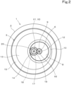
FIG. 2] FIG. 2 is a cross-sectional view taken along Y-Y ofFIG. 1 , in which meshing between an internally toothed gear portion, an externally toothed gear portion, a first external teeth, and a second external teeth is illustrated. - [
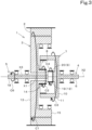
FIG. 3] FIG. 3 is a diagram illustrating operation performed in a case where the rotating electrical machine functions as a motor. - [
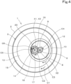
FIG. 4] FIG. 4 illustrates operation performed in a case where the rotating electrical machine functions as a motor. - [
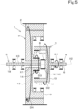
FIG. 5] FIG. 5 illustrates operation performed in a case where the rotating electrical machine functions as a generator. - [
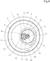
FIG. 6] FIG. 6 illustrates operation performed in a case where the rotating electrical machine functions as a generator. - [
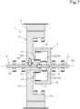
FIG. 7] FIG. 7 illustrates power transmission performed in a case where the rotating electrical machine is used for a parallel hybrid power transmission mechanism. - [
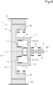
FIG. 8] FIG. 8 is a cross-sectional view of a variation of the rotating electrical machine (in which an output shaft and the like are not illustrated). - Preferred embodiments of a rotating
electrical machine 1 according to the present invention will now be explained while referring to the drawings. The rotatingelectrical machine 1 is a motor, a generator, a motor/generator, or the like. - An embodiment of the rotating
electrical machine 1 according to the present invention is illustrated inFIGS. 1 and2 . - The rotating
electrical machine 1 includes astator 2, arotor 3, aninput member 4, and anoutput member 5. The rotatingelectrical machine 1 is housed inside acontainer 24 such as, for example, a transmission case or a motor casing. - The
stator 2 has a tubular shape (cylindrical shape) and is housed inside thecontainer 24 in a non-rotatable manner. Thestator 2 includes, for example, a stator core and coil(s). Therotor 3 is located radially inward of thestator 2 and is rotatable. Therotor 3 includes, for example, a rotor core and permanent magnet(s). - To facilitate an explanation, the direction indicated by arrow A in
FIG. 1 will be hereinafter referred to as forward, and the direction indicated by arrow B inFIG. 1 will be hereinafter referred to as rearward. An axis about which therotor 3 rotates (such an axis is hereinafter referred to as a rotation axis X1) extends in a front-rear direction. - The
input member 4 includes aninput shaft 6 and apower transmission portion 7. - The
input shaft 6 is a shaft through which rotation power is inputted into therotor 3. Theinput shaft 6 extends in the front-rear direction. Theinput shaft 6 is rotatable about an axis X2. The axis X2 of theinput shaft 6 deviates from the direction in which the rotation axis X1 of therotor 3 extends, and does not coincide with the rotation axis X1 (seeFIG. 2 ). More particularly, the axis X2 of theinput shaft 6 is not on the same axis as the direction in which the rotation axis X1 of therotor 3 extends, but extends in parallel to the rotation axis X1. The outer circumferential surface of theinput shaft 6 is supported by afirst bearing 21. Thefirst bearing 21 supports theinput member 4 such that theinput member 4 is rotatable about the axis X2. - The
power transmission portion 7 is a portion via which power is transmitted between theinput shaft 6 and other members (therotor 3, the output member 5). Thepower transmission portion 7 includes an internallytoothed gear portion 8 and an externallytoothed gear portion 9. Thepower transmission portion 7 is integral with theinput shaft 6. Therefore, the internallytoothed gear portion 8 and the externallytoothed gear portion 9, which are included in thepower transmission portion 7, rotate around the axis X2 as theinput shaft 6 rotates. - The
power transmission portion 7 includes asubstrate 10, an outer protrudingportion 11, and a central protrudingportion 12. Thesubstrate 10 in the form of a disc. One end portion of theinput shaft 6 is connected to the center of thesubstrate 10. Theinput shaft 6 extends from the center of thesubstrate 10 in a direction away from the rotor 3 (extends rearward). The outer protrudingportion 11 has a cylindrical shape and extends from a peripheral portion of thesubstrate 10 toward the rotor 3 (extends forward). The internallytoothed gear portion 8 is provided radially inward of the outer protrudingportion 11. The central protrudingportion 12 extends from the center of thesubstrate 10 toward the rotor 3 (extends forward). The externallytoothed gear portion 9 is provided radially outward of the central protrudingportion 12. The central protrudingportion 12 is located radially inward of the outer protrudingportion 11. The externallytoothed gear portion 9 is located radially inward of the internallytoothed gear portion 8. Note that the central protrudingportion 12 and the externallytoothed gear portion 9 are not illustrated inFIG. 1 , because they are hidden by agear portion 19 and second external teeth 20 (which will be described later). The central protrudingportion 12 and the externallytoothed gear portion 9 are located behind thegear portion 19 and the secondexternal teeth 20 as viewed from a viewer ofFIG. 1 . - As illustrated in
FIG. 1 , the degree of protrusion of the outer protrudingportion 11 from thesubstrate 10 is larger than the degree of protrusion of the central protrudingportion 12 from thesubstrate 10. Therefore, the externallytoothed gear portion 9 and the internallytoothed gear portion 8 are displaced from each other in the direction of the axis X2 of theinput shaft 6. Specifically, the internallytoothed gear portion 8 is located forward of the externallytoothed gear portion 9 along the direction of the axis X2 of theinput shaft 6. - The
rotor 3 includes abase portion 13, aboss portion 14, and an outerannular portion 15. - The
base portion 13 is in the form of a disc. Theboss portion 14 has a cylindrical shape and protrudes from the center of thebase portion 13 toward the input shaft 6 (protrudes rearward). Therotor 3 has a throughhole 16. The throughhole 16 passes through theboss portion 14 and thebase portion 13 in the front-rear direction. The center of the throughhole 16 is located on the rotation axis X1 of therotor 3. Therotor 3 includes firstexternal teeth 17 to mesh with the internallytoothed gear portion 8. The firstexternal teeth 17 are provided on the outer circumferential surface of theboss portion 14. That is, an externally toothed gear including the firstexternal teeth 17 is provided on the outer circumferential surface of theboss portion 14. The firstexternal teeth 17 are located radially inward of the internallytoothed gear portion 8. - The outer
annular portion 15 is a cylindrical portion located radially outward of theboss portion 14. The outerannular portion 15 extends from a peripheral portion of thebase portion 13 toward the input shaft 6 (extends rearward). The outer circumferential surface of the outerannular portion 15 is located near and opposite the inner circumferential surface of thestator 2. The inner circumferential surface of the outerannular portion 15 is supported by asecond bearing 22. Thesecond bearing 22 supports therotor 3 such that therotor 3 is rotatable about the rotation axis X1. Thesecond bearing 22 is located between the outerannular portion 15 and thepower transmission portion 7. In other words, thesecond bearing 22 is located radially inward of the outerannular portion 15 and radially outward of thepower transmission portion 7. The internallytoothed gear portion 8 is located between theboss portion 14 and the outerannular portion 15. That is, theboss portion 14 is located radially inward of the internallytoothed gear portion 8, and the outerannular portion 15 is located radially outward of the internallytoothed gear portion 8. - As illustrated in
FIG. 1 , the outerannular portion 15, theboss portion 14, and the outer protrudingportion 11 overlap with one another in the front-rear direction. Therefore, the outer protrudingportion 11 and theboss portion 14 are arranged in a nested manner, and the outerannular portion 15 and the outer protrudingportion 11 are arranged in a nested manner. - The
output member 5 includes anoutput shaft 18 and thegear portion 19. Theoutput shaft 18 is a shaft through which rotation power is outputted from therotor 3. Theoutput shaft 18 is rotatable about an axis X3. Theoutput shaft 18 extends in the front-rear direction. The axis X3 of theoutput shaft 18 is on the same axis as the direction in which the rotation axis X1 of therotor 3 extends. Theoutput shaft 18 passes through therotor 3. More particularly, theoutput shaft 18 is inserted through the throughhole 16 in therotor 3. There is a gap between the outer circumferential surface of theoutput shaft 18 and the inner circumferential surface of the throughhole 16. - The
gear portion 19 is provided on one end portion (rear end portion) of theoutput shaft 18. Theoutput shaft 18 extends from thegear portion 19 in a direction away from the input shaft 6 (extends forward). Thegear portion 19 includes the secondexternal teeth 20 to mesh with the externallytoothed gear portion 9. The secondexternal teeth 20 are located radially inward of the internallytoothed gear portion 8. The direction in which the axis X3 of theoutput shaft 18 extends is not on the same axis as the direction in which the axis X2 of theinput shaft 6 extends, but is parallel to the direction in which the axis X2 extends. The outer circumferential surface of theoutput shaft 18 is supported by athird bearing 23. Thethird bearing 23 supports theoutput member 5 including theoutput shaft 18 such that theoutput member 5 is rotatable about the axis X3. - The rotating
electrical machine 1 according to the embodiment described above includes the input shaft 6 (the input member 4) and the output shaft 18 (the output member 5). However, the rotatingelectrical machine 1 according to the present invention may have a structure including the input shaft 6 (the input member 4) but not including the output shaft 18 (the output member 5) (seeFIG. 8 ). The rotatingelectrical machine 1 not including theoutput shaft 18 can be used as a generator. The rotatingelectrical machine 1 not including theoutput shaft 18 will be described in detail later. - The rotating
electrical machine 1 can be placed inside a transmission case or a motor casing. With this, it is possible to supply, to the rotatingelectrical machine 1, transmission oil or hydraulic fluid supplied to the inside of the transmission case or the motor casing. This makes it possible to lubricate gears (the externallytoothed gear portion 9, the internallytoothed gear portion 8, the firstexternal teeth 17, and the second external teeth 20) of the rotatingelectrical machine 1 and cool the rotatingelectrical machine 1 using the transmission oil or the hydraulic fluid supplied to the inside of the transmission case or the motor casing. This makes it unnecessary to provide separate structure(s) to lubricate and/or cool the rotatingelectrical machine 1 independently of a structure for supplying the transmission oil or the hydraulic fluid. - The rotating
electrical machine 1 functions as a motor in which therotor 3 rotates about the rotation axis X1, when electric current is passed through the coil(s) of thestator 2. In this case, the rotation power of therotor 3 is taken out through theoutput shaft 18. As illustrated inFIGS. 3 and4 , when therotor 3 rotates about the rotation axis X1 (see arrow C1), theboss portion 14 also rotates (see arrow C2), and the internallytoothed gear portion 8 meshing with the firstexternal teeth 17 on theboss portion 14 rotates (see arrow C3). As the internallytoothed gear portion 8 rotates, theinput member 4 rotates, and therefore the externallytoothed gear portion 9 also rotates (see arrow C4). As the externallytoothed gear portion 9 rotates, the secondexternal teeth 20 meshing with the externallytoothed gear portion 9 rotates (see arrow C5), and theoutput shaft 18 rotates (see arrow C6). Theoutput shaft 18 is connected to driven device(s) such as hydraulic pump(s). The driven device(s) is/are driven by the rotation of theoutput shaft 18. Thus, the rotatingelectrical machine 1 is capable of functioning as a motor that drives the driven device(s) connected to theoutput shaft 18. - The rotating
electrical machine 1 functions as a generator in which an electromotive force is generated in the coil(s) of thestator 2, when therotor 3 rotates about the rotation axis X1 at a position radially inward of thestator 2. In this case, rotation power is inputted into therotor 3 through theinput shaft 6. As illustrated inFIGS. 5 and6 , as theinput shaft 6 rotates (see arrow D1), the internallytoothed gear portion 8 rotates (see arrow D2), and theboss portion 14 having the firstexternal teeth 17 meshing with the internallytoothed gear portion 8 rotates (see arrow D3). As theboss portion 14 rotates, therotor 3 rotates (see arrow D4), and an electromotive force is generated in the coil(s) of thestator 2. The generated electromotive force is taken out through conducting wire(s) connected to the coil(s), and is then stored into, for example, a battery. Thus, the rotatingelectrical machine 1 is capable of functioning as a generator that generates an electromotive force. - In the rotating
electrical machine 1, in a case where rotation power is inputted into therotor 3 through theinput shaft 6, the rotation power from theinput shaft 6 is transmitted by the meshing of the internallytoothed gear portion 8 of theinput member 4 with the firstexternal teeth 17 of therotor 3. Therefore, it is possible to cause therotor 3 to rotate at a higher speed than theinput shaft 6. Therefore, it is possible to obtain output with high rotation speed while achieving a reduction in size of the rotatingelectrical machine 1. Moreover, since such high-speed rotation reduces the necessary amount of current and reduces heat generation, it is possible to improve the efficiency of the rotatingelectrical machine 1 and also reduce the size of a cooling device that cools the rotatingelectrical machine 1. - As described above, the rotating
electrical machine 1 can be caused to function as a motor, can be caused to function as a generator, and can be caused to function as a motor/generator. - In a case where the rotating
electrical machine 1 is caused to function as a motor/generator, it can be used for a parallel hybrid power transmission mechanism. In this case, theinput shaft 6 rotates using power from a prime mover such as an engine. As theinput shaft 6 rotates, the externallytoothed gear portion 9 rotates, and thegear portion 19 having the secondexternal teeth 20 meshing with the externallytoothed gear portion 9 rotates. Due to the rotation of thegear portion 19, theoutput shaft 18 also rotates. Therefore, the driven device(s) (for example, hydraulic pump(s) and/or the like) connected to theoutput shaft 18 is/are driven. Furthermore, as theinput shaft 6 rotates, the internallytoothed gear portion 8 rotates, and theboss portion 14 having the firstexternal teeth 17 meshing with the internallytoothed gear portion 8 rotates. As theboss portion 14 rotates, therotor 3 rotates, and an electromotive force is generated in the coil(s) of thestator 2. Electric power resulting from the electromotive force generated in the coil(s) is stored into the battery. - Then, when the rotating
electrical machine 1 is driven using the power stored in the battery in addition to being driven by the prime mover, therotor 3 rotates, and the rotation power from therotor 3 is transmitted through the firstexternal teeth 17 to the internallytoothed gear portion 8, and the externallytoothed gear portion 9 rotates together with the internallytoothed gear portion 8. As the externallytoothed gear portion 9 rotates, the secondexternal teeth 20 rotate, and theoutput shaft 18 rotates. That is, as illustrated inFIG. 7 , theoutput shaft 18 rotates using power E1 from the prime mover which is inputted via theinput shaft 4, and rotation power E2 from therotor 3. In other words, using the rotation power E2 from therotor 3, it is possible to assist the power E1 transmitted from the prime mover to the driven device(s) via theoutput shaft 18. - In a case where the rotating
electrical machine 1 is used for a parallel hybrid power transmission mechanism as described above, since theinput shaft 6 and theoutput shaft 18 extend in the front-rear direction in parallel to each other, a substantially in-line structure is obtained. This facilitates input into and output from the rotatingelectrical machine 1 and makes it possible to make the structure of the rotatingelectrical machine 1 compact. - In a case where the rotating
electrical machine 1 is caused to function as a generator, it can also be used for a series hybrid power transmission mechanism. In this case, theinput shaft 6 rotates using power from an engine or the like. As theinput shaft 6 rotates, therotor 3 rotates in the same manner (via the same actions) as in the case of the foregoing parallel hybrid power transmission mechanism, and an electromotive force is generated in the coil(s) of thestator 2. Electric power resulting from the electromotive force generated in the coil(s) is stored into the battery. The electric power stored in the battery is used to drive a motor provided separately from the rotatingelectrical machine 1, and the driven device(s) (for example, hydraulic pump(s) and/or the like) is/are driven by this motor. - In a case where the rotating
electrical machine 1 is used for a series hybrid power transmission mechanism as described above, theoutput shaft 18 is unnecessary because the rotatingelectrical machine 1 needs only function as a generator without functioning as a motor. Therefore, as illustrated inFIG. 8 , the rotatingelectrical machine 1 can have a configuration different from that ofFIG. 1 in that theoutput member 5 including theoutput shaft 18, thethird bearing 23, thegear portion 19 including the secondexternal teeth 20, and the throughhole 16 are not included. This makes it possible to make the structure of the rotatingelectrical machine 1 more compact. In particular, omitting theoutput shaft 18 makes it possible to reduce the dimension of the rotatingelectrical machine 1 in the front-rear direction and thus contributes significantly to achieving compactness. Omitting theoutput shaft 18, etc. is also advantageous in that the number of parts of the rotatingelectrical machine 1 can be reduced and the number of man hours for assembly can be reduced. - A rotating
electrical machine 1 according to the above-described embodiments achieves the following effect(s). - A rotating
electrical machine 1 includes astator 2, arotor 3 located radially inward of thestator 2 and being rotatable, and aninput member 4 including aninput shaft 6 through which rotation power is inputted into therotor 3, wherein theinput member 4 includes an internallytoothed gear portion 8 to rotate as theinput shaft 6 rotates, and therotor 3 includes firstexternal teeth 17 to mesh with the internallytoothed gear portion 8. - This configuration makes it possible to provide a rotating
electrical machine 1 that achieves compactness and high efficiency with a simple structure. More particularly, in a case where rotation power is inputted into therotor 3 through theinput shaft 6, the rotation power from theinput shaft 6 is transmitted by the meshing of the internallytoothed gear portion 8 with the firstexternal teeth 17 of therotor 3 and, therefore, it is possible to cause therotor 3 to rotate at a higher speed than theinput shaft 6. Therefore, it is possible to obtain output with high rotation speed while achieving a reduction in size of the rotatingelectrical machine 1. Moreover, since such high-speed rotation reduces the necessary amount of current and reduces heat generation, it is possible to improve the efficiency of the rotatingelectrical machine 1 and also reduce the size of a cooling device that cools the rotatingelectrical machine 1. Consequently, it is possible to achieve compactness and high efficiency of a power transmission mechanism using a rotating electrical machine such as a hybrid-type power transmission mechanism. - The rotating
electrical machine 1 further includes anoutput member 5 including anoutput shaft 18 through which rotation power is outputted from therotor 3. Theinput member 4 includes an externallytoothed gear portion 9 to rotate as theinput shaft 6 rotates. Theoutput member 5 includes secondexternal teeth 20 to mesh with the externallytoothed gear portion 9. - With this configuration, it is possible to cause the
rotor 3 to rotate by the rotation power inputted through theinput member 4 and to take out the rotation power from therotor 3 through theoutput shaft 18 of theoutput member 5. Therefore, it is possible to cause the rotatingelectrical machine 1 to function as a motor/generator and to use the rotatingelectrical machine 1 for a parallel-hybrid power transmission mechanism to achieve compactness and high efficiency of the mechanism. - The first
external teeth 17, the secondexternal teeth 20, and the externallytoothed gear portion 9 are located radially inward of the internallytoothed gear portion 8. - With this configuration, since the first
external teeth 17, the secondexternal teeth 20, and the externallytoothed gear portion 9 are contained in a space radially inward of the internallytoothed gear portion 8, it is possible to reduce the dimension of the rotatingelectrical machine 1 in the direction of the rotation axis of the rotor 3 (the dimension in the front-rear direction) and make the rotatingelectrical machine 1 compact. - The
rotor 3 includes abase portion 13 having a disc shape, aboss portion 14 including the firstexternal teeth 17, and an outerannular portion 15 located radially outward of theboss portion 14. Theboss portion 14 and the outerannular portion 15 protrude from thebase portion 13 toward theinput shaft 6. The internallytoothed gear portion 8 is located between theboss portion 14 and the outerannular portion 15. - With this configuration, since the
boss portion 14 and the outerannular portion 15 are contained in a space radially inward of the internallytoothed gear portion 8, it is possible to reduce the dimension of the rotatingelectrical machine 1 in the direction of the rotation axis of the rotor 3 (the dimension in the front-rear direction) and make the rotatingelectrical machine 1 compact. - The
input member 4 includes theinput shaft 6 and apower transmission portion 7. Thepower transmission portion 7 includes asubstrate 10, an outer protrudingportion 11, and a central protrudingportion 12. One end portion of theinput shaft 6 is connected to a center of thesubstrate 10. The outer protrudingportion 11 has a cylindrical shape and extends from a peripheral portion of thesubstrate 10 toward therotor 3. The internallytoothed gear portion 8 is located radially inward of the outer protrudingportion 11. The central protrudingportion 12 extends from the center of thesubstrate 10 toward therotor 3. The externallytoothed gear portion 9 is provided radially outward of the central protrudingportion 12. The outer protrudingportion 11 and theboss portion 14 are arranged in a nested manner. The outerannular portion 15 and the outer protrudingportion 11 are arranged in a nested manner. - With this configuration, since the outer protruding
portion 11 and theboss portion 14 are arranged in a nested manner and the outerannular portion 15 and the outer protrudingportion 11 are arranged in a nested manner, it is possible to reduce the dimension of the rotatingelectrical machine 1 in the direction of the rotation axis of the rotor 3 (the dimension in the front-rear direction) and make the rotatingelectrical machine 1 compact, despite its simple structure without the need for a complex structure. - The
output shaft 18 extends through therotor 3. - With this configuration, since it is possible to place the axis X3 of the
output shaft 18 on the same axis as the rotation axis X1 of therotor 3, it is possible to reduce the diameter of the rotatingelectrical machine 1 and make the rotatingelectrical machine 1 compact. - A direction in which an axis X2 of the
input shaft 6 extends is not on the same axis as a direction in which an axis X3 of theoutput shaft 18 extends, but is parallel to the direction in which the axis X3 of theoutput shaft 18 extends. - This configuration achieves easy input and output to and from the rotating
electrical machine 1. In addition, this configuration makes the structure of the rotatingelectrical machine 1 compact. - The rotating
electrical machine 1 further includes a bearing (first bearing 21) to support therotor 3 rotatably. The bearing (first bearing 21) supports an inner circumferential surface of the outerannular portion 15. - With this configuration, since it is possible to place the bearing (first bearing 21) within the rotating
electrical machine 1, it is possible to make the rotatingelectrical machine 1 compact. - While embodiments of the present invention have been described above, it is to be understood that the embodiments disclosed herein are considered as examples in all aspects and are not considered as limitations. The scope of the present invention is to be determined not by the foregoing description but by the claims, and is intended to include all variations and modifications within the scope of the claims and their equivalents.
-
- 1
- Rotating electrical machine
- 2
- Stator
- 3
- Rotor
- 4
- Input member
- 5
- Output member
- 6
- Input shaft
- 7
- Power transmission portion
- 8
- Internally toothed gear portion
- 9
- Externally toothed gear portion
- 10
- Substrate
- 11
- Outer protruding portion
- 12
- Central protruding portion
- 13
- Base portion
- 14
- Boss portion
- 15
- Outer annular portion
- 16
- Through hole
- 17
- First external teeth
- 18
- Output shaft
- 19
- Gear portion
- 20
- Second external teeth
- 21
- Bearing (first bearing)
- X1
- Rotation axis of the rotor
- X2
- Shaft center of the input shaft
- X3
- Shaft center of the output shaft
Claims (8)
- A rotating electrical machine, comprising:a stator;a rotor located radially inward of the stator and being rotatable; andan input member including an input shaft through which rotation power is inputted into the rotor, whereinthe input member includes an internally toothed gear portion to rotate as the input shaft rotates, andthe rotor includes first external teeth to mesh with the internally toothed gear portion.
- The rotating electrical machine according to claim 1, further comprising:an output member including an output shaft through which rotation power is outputted from the rotor, whereinthe input member includes an externally toothed gear portion to rotate as the input shaft rotates, andthe output member includes second external teeth to mesh with the externally toothed gear portion.
- The rotating electrical machine according to claim 2, wherein
the first external teeth, the second external teeth, and the externally toothed gear portion are located radially inward of the internally toothed gear portion. - The rotating electrical machine according to any one of claims 1 to 3, whereinthe rotor includes a base portion having a disc shape, a boss portion including the first external teeth, and an outer annular portion located radially outward of the boss portion,the boss portion and the outer annular portion protrude from the base portion toward the input shaft, andthe internally toothed gear portion is located between the boss portion and the outer annular portion.
- The rotating electrical machine according to claim 4 depending from claim 2, whereinthe input member includes the input shaft and a power transmission portion,the power transmission portion includes a substrate, an outer protruding portion, and a central protruding portion,one end portion of the input shaft is connected to a center of the substrate,the outer protruding portion has a cylindrical shape and extends from a peripheral portion of the substrate toward the rotor, and the internally toothed gear portion is located radially inward of the outer protruding portion,the central protruding portion extends from the center of the substrate toward the rotor, and the externally toothed gear portion is provided radially outward of the central protruding portion, andthe outer protruding portion and the boss portion are arranged in a nested manner, and the outer annular portion and the outer protruding portion are arranged in a nested manner.
- The rotating electrical machine according to claim 2 or 3, wherein
the output shaft extends through the rotor. - The rotating electrical machine according to any one of claims 2, 3, and 5, wherein
a direction in which an axis of the input shaft extends is not on the same axis as a direction in which an axis of the output shaft extends, but is parallel to the direction in which the axis of the output shaft extends. - The rotating electrical machine according to claim 4, further comprising:a bearing to support the rotor rotatably, whereinthe bearing supports an inner circumferential surface of the outer annular portion.
Applications Claiming Priority (2)
| Application Number | Priority Date | Filing Date | Title |
|---|---|---|---|
| JP2020161103 | 2020-09-25 | ||
| PCT/JP2021/033528 WO2022065106A1 (en) | 2020-09-25 | 2021-09-13 | Rotary electrical machine |
Publications (2)
| Publication Number | Publication Date |
|---|---|
| EP4219979A1 true EP4219979A1 (en) | 2023-08-02 |
| EP4219979A4 EP4219979A4 (en) | 2024-04-10 |
Family
ID=80845360
Family Applications (1)
| Application Number | Title | Priority Date | Filing Date |
|---|---|---|---|
| EP21872236.1A Pending EP4219979A4 (en) | 2020-09-25 | 2021-09-13 | Rotary electrical machine |
Country Status (4)
| Country | Link |
|---|---|
| US (1) | US12323037B2 (en) |
| EP (1) | EP4219979A4 (en) |
| JP (1) | JP7483912B2 (en) |
| WO (1) | WO2022065106A1 (en) |
Family Cites Families (13)
| Publication number | Priority date | Publication date | Assignee | Title |
|---|---|---|---|---|
| GB728804A (en) * | 1952-10-13 | 1955-04-27 | Gen Electric | Improvements in and relating to driving mechanism of the quill type |
| JP3770220B2 (en) | 2002-10-02 | 2006-04-26 | 国産電機株式会社 | Hybrid motorcycle and power transmission device for hybrid motorcycle |
| JP2007107717A (en) | 2005-09-14 | 2007-04-26 | Ntn Corp | Power transmission and power output device |
| JP4487970B2 (en) * | 2006-04-17 | 2010-06-23 | 三菱電機株式会社 | Electric power steering apparatus and motor for electric power steering apparatus |
| US8409042B2 (en) * | 2009-09-25 | 2013-04-02 | Tai-Her Yang | Externally rotating mechanism through offset outer rotating electrical machine drive |
| SI2946959T1 (en) * | 2014-05-21 | 2020-07-31 | Siegfried Muck | Hybrid drive unit and method for starting a vehicle with a hybrid drive unit |
| JP6459849B2 (en) * | 2015-08-21 | 2019-01-30 | トヨタ自動車株式会社 | Transaxle structure for vehicles |
| JP6526551B2 (en) * | 2015-12-11 | 2019-06-05 | 株式会社クボタ | Parallel hybrid power transmission mechanism |
| CN105743279B (en) | 2016-04-26 | 2018-06-29 | 苏州盛亿电机有限公司 | Electric bicycle compact built-in motor |
| JP6624151B2 (en) * | 2017-04-21 | 2019-12-25 | トヨタ自動車株式会社 | Hybrid four-wheel drive vehicle |
| JP6531141B2 (en) * | 2017-08-29 | 2019-06-12 | 本田技研工業株式会社 | Vehicle drive |
| JP7025945B2 (en) * | 2018-01-31 | 2022-02-25 | 株式会社小松製作所 | Motors, rotary drive systems and hydraulic excavators |
| CN113644783B (en) * | 2021-07-22 | 2023-05-02 | 广东金霸智能科技股份有限公司 | Driving device |
-
2021
- 2021-09-13 EP EP21872236.1A patent/EP4219979A4/en active Pending
- 2021-09-13 WO PCT/JP2021/033528 patent/WO2022065106A1/en not_active Ceased
- 2021-09-13 JP JP2022551893A patent/JP7483912B2/en active Active
-
2023
- 2023-03-15 US US18/121,661 patent/US12323037B2/en active Active
Also Published As
| Publication number | Publication date |
|---|---|
| WO2022065106A1 (en) | 2022-03-31 |
| US12323037B2 (en) | 2025-06-03 |
| US20230223817A1 (en) | 2023-07-13 |
| EP4219979A4 (en) | 2024-04-10 |
| JP7483912B2 (en) | 2024-05-15 |
| JPWO2022065106A1 (en) | 2022-03-31 |
Similar Documents
| Publication | Publication Date | Title |
|---|---|---|
| CN1866686B (en) | Drive train electric motor with planetary gear system | |
| JP5703698B2 (en) | Rotating machine and vehicle | |
| EP4382767A1 (en) | Driving device for vehicle | |
| KR102519998B1 (en) | Drive apparatus | |
| EP3664262B1 (en) | Electric machine systems | |
| EP3294623A1 (en) | A marine vessel propulsion device, a pod unit and a marine vessel. | |
| JP2007039000A (en) | Power transmission device for hybrid vehicle | |
| JP2009195082A (en) | Stator cooling structure | |
| CN118103617A (en) | Vehicle drive device | |
| CN120886230A (en) | Dual-stator single-rotor planetary reduction joint module | |
| WO2017145778A1 (en) | Supercharging device | |
| US12323037B2 (en) | Rotating electrical machine | |
| JP2019119402A (en) | Lubrication device | |
| EP3664261A1 (en) | Electric machine systems | |
| EP3664266A1 (en) | Electric machine systems | |
| CN105743279A (en) | Compact central motor for electric bicycle | |
| JP2004153895A (en) | Electric motor for vehicles | |
| CN104638823A (en) | Variable speed electro-mechanical drive | |
| CN110311508B (en) | Rotary electric machine device and vehicle equipped with rotary electric machine device | |
| CN210693674U (en) | Electric machine | |
| KR20230167555A (en) | In-wheel motor apparatus | |
| CN217422137U (en) | Cooling fan speed increasing mechanism of automobile generator | |
| JP2009296812A (en) | Motor | |
| CN224090025U (en) | Hybrid system | |
| US20250392191A1 (en) | Electric power generators with integrated high-speed and high-power permanent magnet generators |
Legal Events
| Date | Code | Title | Description |
|---|---|---|---|
| STAA | Information on the status of an ep patent application or granted ep patent |
Free format text: STATUS: THE INTERNATIONAL PUBLICATION HAS BEEN MADE |
|
| PUAI | Public reference made under article 153(3) epc to a published international application that has entered the european phase |
Free format text: ORIGINAL CODE: 0009012 |
|
| STAA | Information on the status of an ep patent application or granted ep patent |
Free format text: STATUS: REQUEST FOR EXAMINATION WAS MADE |
|
| 17P | Request for examination filed |
Effective date: 20230309 |
|
| AK | Designated contracting states |
Kind code of ref document: A1 Designated state(s): AL AT BE BG CH CY CZ DE DK EE ES FI FR GB GR HR HU IE IS IT LI LT LU LV MC MK MT NL NO PL PT RO RS SE SI SK SM TR |
|
| DAV | Request for validation of the european patent (deleted) | ||
| DAX | Request for extension of the european patent (deleted) | ||
| REG | Reference to a national code |
Ref country code: DE Ref legal event code: R079 Free format text: PREVIOUS MAIN CLASS: F16H0001100000 Ipc: H02K0007000000 |
|
| A4 | Supplementary search report drawn up and despatched |
Effective date: 20240313 |
|
| RIC1 | Information provided on ipc code assigned before grant |
Ipc: B60K 6/365 20071001ALI20240306BHEP Ipc: B60K 6/48 20071001ALI20240306BHEP Ipc: B60K 6/40 20071001ALI20240306BHEP Ipc: B60K 6/36 20071001ALI20240306BHEP Ipc: B60K 6/26 20071001ALI20240306BHEP Ipc: B60K 1/00 20060101ALI20240306BHEP Ipc: F16H 1/10 20060101ALI20240306BHEP Ipc: H02K 7/08 20060101ALI20240306BHEP Ipc: H02K 7/116 20060101ALI20240306BHEP Ipc: H02K 7/00 20060101AFI20240306BHEP |