EP4219945A1 - Control method for variable volume ratio compressor - Google Patents
Control method for variable volume ratio compressor Download PDFInfo
- Publication number
- EP4219945A1 EP4219945A1 EP23174738.7A EP23174738A EP4219945A1 EP 4219945 A1 EP4219945 A1 EP 4219945A1 EP 23174738 A EP23174738 A EP 23174738A EP 4219945 A1 EP4219945 A1 EP 4219945A1
- Authority
- EP
- European Patent Office
- Prior art keywords
- compressor
- volume ratio
- variable volume
- switching parameter
- switching
- Prior art date
- Legal status (The legal status is an assumption and is not a legal conclusion. Google has not performed a legal analysis and makes no representation as to the accuracy of the status listed.)
- Granted
Links
Images


Classifications
-
- F—MECHANICAL ENGINEERING; LIGHTING; HEATING; WEAPONS; BLASTING
- F04—POSITIVE - DISPLACEMENT MACHINES FOR LIQUIDS; PUMPS FOR LIQUIDS OR ELASTIC FLUIDS
- F04B—POSITIVE-DISPLACEMENT MACHINES FOR LIQUIDS; PUMPS
- F04B49/00—Control, e.g. of pump delivery, or pump pressure of, or safety measures for, machines, pumps, or pumping installations, not otherwise provided for, or of interest apart from, groups F04B1/00 - F04B47/00
- F04B49/06—Control using electricity
- F04B49/065—Control using electricity and making use of computers
-
- F—MECHANICAL ENGINEERING; LIGHTING; HEATING; WEAPONS; BLASTING
- F04—POSITIVE - DISPLACEMENT MACHINES FOR LIQUIDS; PUMPS FOR LIQUIDS OR ELASTIC FLUIDS
- F04C—ROTARY-PISTON, OR OSCILLATING-PISTON, POSITIVE-DISPLACEMENT MACHINES FOR LIQUIDS; ROTARY-PISTON, OR OSCILLATING-PISTON, POSITIVE-DISPLACEMENT PUMPS
- F04C28/00—Control of, monitoring of, or safety arrangements for, pumps or pumping installations specially adapted for elastic fluids
- F04C28/18—Control of, monitoring of, or safety arrangements for, pumps or pumping installations specially adapted for elastic fluids characterised by varying the volume of the working chamber
-
- F—MECHANICAL ENGINEERING; LIGHTING; HEATING; WEAPONS; BLASTING
- F25—REFRIGERATION OR COOLING; COMBINED HEATING AND REFRIGERATION SYSTEMS; HEAT PUMP SYSTEMS; MANUFACTURE OR STORAGE OF ICE; LIQUEFACTION SOLIDIFICATION OF GASES
- F25B—REFRIGERATION MACHINES, PLANTS OR SYSTEMS; COMBINED HEATING AND REFRIGERATION SYSTEMS; HEAT PUMP SYSTEMS
- F25B1/00—Compression machines, plants or systems with non-reversible cycle
-
- F—MECHANICAL ENGINEERING; LIGHTING; HEATING; WEAPONS; BLASTING
- F04—POSITIVE - DISPLACEMENT MACHINES FOR LIQUIDS; PUMPS FOR LIQUIDS OR ELASTIC FLUIDS
- F04B—POSITIVE-DISPLACEMENT MACHINES FOR LIQUIDS; PUMPS
- F04B37/00—Pumps having pertinent characteristics not provided for in, or of interest apart from, groups F04B25/00 - F04B35/00
- F04B37/10—Pumps having pertinent characteristics not provided for in, or of interest apart from, groups F04B25/00 - F04B35/00 for special use
- F04B37/12—Pumps having pertinent characteristics not provided for in, or of interest apart from, groups F04B25/00 - F04B35/00 for special use to obtain high pressure
-
- F—MECHANICAL ENGINEERING; LIGHTING; HEATING; WEAPONS; BLASTING
- F04—POSITIVE - DISPLACEMENT MACHINES FOR LIQUIDS; PUMPS FOR LIQUIDS OR ELASTIC FLUIDS
- F04B—POSITIVE-DISPLACEMENT MACHINES FOR LIQUIDS; PUMPS
- F04B39/00—Component parts, details, or accessories, of pumps or pumping systems specially adapted for elastic fluids, not otherwise provided for in, or of interest apart from, groups F04B25/00 - F04B37/00
-
- F—MECHANICAL ENGINEERING; LIGHTING; HEATING; WEAPONS; BLASTING
- F04—POSITIVE - DISPLACEMENT MACHINES FOR LIQUIDS; PUMPS FOR LIQUIDS OR ELASTIC FLUIDS
- F04B—POSITIVE-DISPLACEMENT MACHINES FOR LIQUIDS; PUMPS
- F04B39/00—Component parts, details, or accessories, of pumps or pumping systems specially adapted for elastic fluids, not otherwise provided for in, or of interest apart from, groups F04B25/00 - F04B37/00
- F04B39/10—Adaptations or arrangements of distribution members
-
- F—MECHANICAL ENGINEERING; LIGHTING; HEATING; WEAPONS; BLASTING
- F04—POSITIVE - DISPLACEMENT MACHINES FOR LIQUIDS; PUMPS FOR LIQUIDS OR ELASTIC FLUIDS
- F04B—POSITIVE-DISPLACEMENT MACHINES FOR LIQUIDS; PUMPS
- F04B39/00—Component parts, details, or accessories, of pumps or pumping systems specially adapted for elastic fluids, not otherwise provided for in, or of interest apart from, groups F04B25/00 - F04B37/00
- F04B39/12—Casings; Cylinders; Cylinder heads; Fluid connections
- F04B39/123—Fluid connections
-
- F—MECHANICAL ENGINEERING; LIGHTING; HEATING; WEAPONS; BLASTING
- F04—POSITIVE - DISPLACEMENT MACHINES FOR LIQUIDS; PUMPS FOR LIQUIDS OR ELASTIC FLUIDS
- F04B—POSITIVE-DISPLACEMENT MACHINES FOR LIQUIDS; PUMPS
- F04B49/00—Control, e.g. of pump delivery, or pump pressure of, or safety measures for, machines, pumps, or pumping installations, not otherwise provided for, or of interest apart from, groups F04B1/00 - F04B47/00
- F04B49/22—Control, e.g. of pump delivery, or pump pressure of, or safety measures for, machines, pumps, or pumping installations, not otherwise provided for, or of interest apart from, groups F04B1/00 - F04B47/00 by means of valves
-
- F—MECHANICAL ENGINEERING; LIGHTING; HEATING; WEAPONS; BLASTING
- F04—POSITIVE - DISPLACEMENT MACHINES FOR LIQUIDS; PUMPS FOR LIQUIDS OR ELASTIC FLUIDS
- F04B—POSITIVE-DISPLACEMENT MACHINES FOR LIQUIDS; PUMPS
- F04B49/00—Control, e.g. of pump delivery, or pump pressure of, or safety measures for, machines, pumps, or pumping installations, not otherwise provided for, or of interest apart from, groups F04B1/00 - F04B47/00
- F04B49/22—Control, e.g. of pump delivery, or pump pressure of, or safety measures for, machines, pumps, or pumping installations, not otherwise provided for, or of interest apart from, groups F04B1/00 - F04B47/00 by means of valves
- F04B49/225—Control, e.g. of pump delivery, or pump pressure of, or safety measures for, machines, pumps, or pumping installations, not otherwise provided for, or of interest apart from, groups F04B1/00 - F04B47/00 by means of valves with throttling valves or valves varying the pump inlet opening or the outlet opening
-
- F—MECHANICAL ENGINEERING; LIGHTING; HEATING; WEAPONS; BLASTING
- F04—POSITIVE - DISPLACEMENT MACHINES FOR LIQUIDS; PUMPS FOR LIQUIDS OR ELASTIC FLUIDS
- F04C—ROTARY-PISTON, OR OSCILLATING-PISTON, POSITIVE-DISPLACEMENT MACHINES FOR LIQUIDS; ROTARY-PISTON, OR OSCILLATING-PISTON, POSITIVE-DISPLACEMENT PUMPS
- F04C28/00—Control of, monitoring of, or safety arrangements for, pumps or pumping installations specially adapted for elastic fluids
- F04C28/24—Control of, monitoring of, or safety arrangements for, pumps or pumping installations specially adapted for elastic fluids characterised by using valves controlling pressure or flow rate, e.g. discharge valves or unloading valves
-
- F—MECHANICAL ENGINEERING; LIGHTING; HEATING; WEAPONS; BLASTING
- F25—REFRIGERATION OR COOLING; COMBINED HEATING AND REFRIGERATION SYSTEMS; HEAT PUMP SYSTEMS; MANUFACTURE OR STORAGE OF ICE; LIQUEFACTION SOLIDIFICATION OF GASES
- F25B—REFRIGERATION MACHINES, PLANTS OR SYSTEMS; COMBINED HEATING AND REFRIGERATION SYSTEMS; HEAT PUMP SYSTEMS
- F25B31/00—Compressor arrangements
-
- F—MECHANICAL ENGINEERING; LIGHTING; HEATING; WEAPONS; BLASTING
- F25—REFRIGERATION OR COOLING; COMBINED HEATING AND REFRIGERATION SYSTEMS; HEAT PUMP SYSTEMS; MANUFACTURE OR STORAGE OF ICE; LIQUEFACTION SOLIDIFICATION OF GASES
- F25B—REFRIGERATION MACHINES, PLANTS OR SYSTEMS; COMBINED HEATING AND REFRIGERATION SYSTEMS; HEAT PUMP SYSTEMS
- F25B31/00—Compressor arrangements
- F25B31/02—Compressor arrangements of motor-compressor units
- F25B31/023—Compressor arrangements of motor-compressor units with compressor of reciprocating-piston type
-
- F—MECHANICAL ENGINEERING; LIGHTING; HEATING; WEAPONS; BLASTING
- F25—REFRIGERATION OR COOLING; COMBINED HEATING AND REFRIGERATION SYSTEMS; HEAT PUMP SYSTEMS; MANUFACTURE OR STORAGE OF ICE; LIQUEFACTION SOLIDIFICATION OF GASES
- F25B—REFRIGERATION MACHINES, PLANTS OR SYSTEMS; COMBINED HEATING AND REFRIGERATION SYSTEMS; HEAT PUMP SYSTEMS
- F25B41/00—Fluid-circulation arrangements
- F25B41/20—Disposition of valves, e.g. of on-off valves or flow control valves
-
- F—MECHANICAL ENGINEERING; LIGHTING; HEATING; WEAPONS; BLASTING
- F25—REFRIGERATION OR COOLING; COMBINED HEATING AND REFRIGERATION SYSTEMS; HEAT PUMP SYSTEMS; MANUFACTURE OR STORAGE OF ICE; LIQUEFACTION SOLIDIFICATION OF GASES
- F25B—REFRIGERATION MACHINES, PLANTS OR SYSTEMS; COMBINED HEATING AND REFRIGERATION SYSTEMS; HEAT PUMP SYSTEMS
- F25B49/00—Arrangement or mounting of control or safety devices
- F25B49/02—Arrangement or mounting of control or safety devices for compression type machines, plants or systems
-
- F—MECHANICAL ENGINEERING; LIGHTING; HEATING; WEAPONS; BLASTING
- F04—POSITIVE - DISPLACEMENT MACHINES FOR LIQUIDS; PUMPS FOR LIQUIDS OR ELASTIC FLUIDS
- F04B—POSITIVE-DISPLACEMENT MACHINES FOR LIQUIDS; PUMPS
- F04B2203/00—Motor parameters
- F04B2203/02—Motor parameters of rotating electric motors
- F04B2203/0209—Rotational speed
-
- F—MECHANICAL ENGINEERING; LIGHTING; HEATING; WEAPONS; BLASTING
- F04—POSITIVE - DISPLACEMENT MACHINES FOR LIQUIDS; PUMPS FOR LIQUIDS OR ELASTIC FLUIDS
- F04B—POSITIVE-DISPLACEMENT MACHINES FOR LIQUIDS; PUMPS
- F04B2205/00—Fluid parameters
- F04B2205/09—Flow through the pump
-
- F—MECHANICAL ENGINEERING; LIGHTING; HEATING; WEAPONS; BLASTING
- F04—POSITIVE - DISPLACEMENT MACHINES FOR LIQUIDS; PUMPS FOR LIQUIDS OR ELASTIC FLUIDS
- F04C—ROTARY-PISTON, OR OSCILLATING-PISTON, POSITIVE-DISPLACEMENT MACHINES FOR LIQUIDS; ROTARY-PISTON, OR OSCILLATING-PISTON, POSITIVE-DISPLACEMENT PUMPS
- F04C2210/00—Fluid
- F04C2210/26—Refrigerants with particular properties, e.g. HFC-134a
-
- F—MECHANICAL ENGINEERING; LIGHTING; HEATING; WEAPONS; BLASTING
- F04—POSITIVE - DISPLACEMENT MACHINES FOR LIQUIDS; PUMPS FOR LIQUIDS OR ELASTIC FLUIDS
- F04C—ROTARY-PISTON, OR OSCILLATING-PISTON, POSITIVE-DISPLACEMENT MACHINES FOR LIQUIDS; ROTARY-PISTON, OR OSCILLATING-PISTON, POSITIVE-DISPLACEMENT PUMPS
- F04C2240/00—Components
- F04C2240/80—Other components
- F04C2240/81—Sensor, e.g. electronic sensor for control or monitoring
-
- F—MECHANICAL ENGINEERING; LIGHTING; HEATING; WEAPONS; BLASTING
- F04—POSITIVE - DISPLACEMENT MACHINES FOR LIQUIDS; PUMPS FOR LIQUIDS OR ELASTIC FLUIDS
- F04C—ROTARY-PISTON, OR OSCILLATING-PISTON, POSITIVE-DISPLACEMENT MACHINES FOR LIQUIDS; ROTARY-PISTON, OR OSCILLATING-PISTON, POSITIVE-DISPLACEMENT PUMPS
- F04C2270/00—Control; Monitoring or safety arrangements
- F04C2270/05—Speed
- F04C2270/052—Speed angular
-
- F—MECHANICAL ENGINEERING; LIGHTING; HEATING; WEAPONS; BLASTING
- F25—REFRIGERATION OR COOLING; COMBINED HEATING AND REFRIGERATION SYSTEMS; HEAT PUMP SYSTEMS; MANUFACTURE OR STORAGE OF ICE; LIQUEFACTION SOLIDIFICATION OF GASES
- F25B—REFRIGERATION MACHINES, PLANTS OR SYSTEMS; COMBINED HEATING AND REFRIGERATION SYSTEMS; HEAT PUMP SYSTEMS
- F25B1/00—Compression machines, plants or systems with non-reversible cycle
- F25B1/02—Compression machines, plants or systems with non-reversible cycle with compressor of reciprocating-piston type
-
- F—MECHANICAL ENGINEERING; LIGHTING; HEATING; WEAPONS; BLASTING
- F25—REFRIGERATION OR COOLING; COMBINED HEATING AND REFRIGERATION SYSTEMS; HEAT PUMP SYSTEMS; MANUFACTURE OR STORAGE OF ICE; LIQUEFACTION SOLIDIFICATION OF GASES
- F25B—REFRIGERATION MACHINES, PLANTS OR SYSTEMS; COMBINED HEATING AND REFRIGERATION SYSTEMS; HEAT PUMP SYSTEMS
- F25B2600/00—Control issues
- F25B2600/25—Control of valves
-
- F—MECHANICAL ENGINEERING; LIGHTING; HEATING; WEAPONS; BLASTING
- F25—REFRIGERATION OR COOLING; COMBINED HEATING AND REFRIGERATION SYSTEMS; HEAT PUMP SYSTEMS; MANUFACTURE OR STORAGE OF ICE; LIQUEFACTION SOLIDIFICATION OF GASES
- F25B—REFRIGERATION MACHINES, PLANTS OR SYSTEMS; COMBINED HEATING AND REFRIGERATION SYSTEMS; HEAT PUMP SYSTEMS
- F25B2700/00—Sensing or detecting of parameters; Sensors therefor
- F25B2700/17—Speeds
- F25B2700/171—Speeds of the compressor
-
- F—MECHANICAL ENGINEERING; LIGHTING; HEATING; WEAPONS; BLASTING
- F25—REFRIGERATION OR COOLING; COMBINED HEATING AND REFRIGERATION SYSTEMS; HEAT PUMP SYSTEMS; MANUFACTURE OR STORAGE OF ICE; LIQUEFACTION SOLIDIFICATION OF GASES
- F25B—REFRIGERATION MACHINES, PLANTS OR SYSTEMS; COMBINED HEATING AND REFRIGERATION SYSTEMS; HEAT PUMP SYSTEMS
- F25B2700/00—Sensing or detecting of parameters; Sensors therefor
- F25B2700/19—Pressures
- F25B2700/193—Pressures of the compressor
- F25B2700/1933—Suction pressures
-
- F—MECHANICAL ENGINEERING; LIGHTING; HEATING; WEAPONS; BLASTING
- F25—REFRIGERATION OR COOLING; COMBINED HEATING AND REFRIGERATION SYSTEMS; HEAT PUMP SYSTEMS; MANUFACTURE OR STORAGE OF ICE; LIQUEFACTION SOLIDIFICATION OF GASES
- F25B—REFRIGERATION MACHINES, PLANTS OR SYSTEMS; COMBINED HEATING AND REFRIGERATION SYSTEMS; HEAT PUMP SYSTEMS
- F25B2700/00—Sensing or detecting of parameters; Sensors therefor
- F25B2700/21—Temperatures
- F25B2700/2113—Temperatures of a suction accumulator
-
- F—MECHANICAL ENGINEERING; LIGHTING; HEATING; WEAPONS; BLASTING
- F25—REFRIGERATION OR COOLING; COMBINED HEATING AND REFRIGERATION SYSTEMS; HEAT PUMP SYSTEMS; MANUFACTURE OR STORAGE OF ICE; LIQUEFACTION SOLIDIFICATION OF GASES
- F25B—REFRIGERATION MACHINES, PLANTS OR SYSTEMS; COMBINED HEATING AND REFRIGERATION SYSTEMS; HEAT PUMP SYSTEMS
- F25B2700/00—Sensing or detecting of parameters; Sensors therefor
- F25B2700/21—Temperatures
- F25B2700/2115—Temperatures of a compressor or the drive means therefor
- F25B2700/21151—Temperatures of a compressor or the drive means therefor at the suction side of the compressor
-
- F—MECHANICAL ENGINEERING; LIGHTING; HEATING; WEAPONS; BLASTING
- F25—REFRIGERATION OR COOLING; COMBINED HEATING AND REFRIGERATION SYSTEMS; HEAT PUMP SYSTEMS; MANUFACTURE OR STORAGE OF ICE; LIQUEFACTION SOLIDIFICATION OF GASES
- F25B—REFRIGERATION MACHINES, PLANTS OR SYSTEMS; COMBINED HEATING AND REFRIGERATION SYSTEMS; HEAT PUMP SYSTEMS
- F25B49/00—Arrangement or mounting of control or safety devices
- F25B49/02—Arrangement or mounting of control or safety devices for compression type machines, plants or systems
- F25B49/022—Compressor control arrangements
-
- Y—GENERAL TAGGING OF NEW TECHNOLOGICAL DEVELOPMENTS; GENERAL TAGGING OF CROSS-SECTIONAL TECHNOLOGIES SPANNING OVER SEVERAL SECTIONS OF THE IPC; TECHNICAL SUBJECTS COVERED BY FORMER USPC CROSS-REFERENCE ART COLLECTIONS [XRACs] AND DIGESTS
- Y02—TECHNOLOGIES OR APPLICATIONS FOR MITIGATION OR ADAPTATION AGAINST CLIMATE CHANGE
- Y02B—CLIMATE CHANGE MITIGATION TECHNOLOGIES RELATED TO BUILDINGS, e.g. HOUSING, HOUSE APPLIANCES OR RELATED END-USER APPLICATIONS
- Y02B30/00—Energy efficient heating, ventilation or air conditioning [HVAC]
- Y02B30/70—Efficient control or regulation technologies, e.g. for control of refrigerant flow, motor or heating
Definitions
- This disclosure is directed to methods and systems for controlling valves governing the volume ratio of a variable volume ratio compressor. Particularly, this disclosure is directed to controlling the volume ratio of a compressor based on compressor mass flow, determined through inputs such as suction density and compressor speed.
- Compressors can incorporate hardware allowing the volume ratio of the compressor to be adjusted. Changing the volume ratio of a compressor affects the conditions at the discharge of the compressor. Changes to the volume ratio can affect compressor performance under partial load conditions, increasing or decreasing the efficiency of the compressor at partial and full loads depending on whether the volume ratio is properly selected for a set of operating conditions of the compressor.
- This disclosure is directed to methods and systems for controlling valves governing the volume ratio of a variable volume ratio compressor. Particularly, this disclosure is directed to controlling the volume ratio of a compressor based on compressor mass flow, determined through inputs such as suction density and compressor speed.
- Variable volume ratio compressors allow the volume ratio to be changed between at least two settings, which can improve matching of compressor discharge conditions to pressure conditions at a condenser of a refrigerant circuit that includes the compressor so as to increase efficiency.
- volume ratios may occur at high frequencies. Such high-frequency switching could create additional wear on the variable volume ratio system components. Delay periods may be incorporated into determining and implementing changes to the volume ratio, providing more consistent operation over time and reducing potentially excessive changes in the volume ratio of the compressor.
- a compressor system in an embodiment, includes a variable volume ratio compressor configured to be operated at one of a plurality of different volume ratios and having a suction.
- the compressor system also includes a controller.
- the controller is configured to obtain a speed of operation of the variable volume ratio compressor and a refrigerant density at the suction of the variable volume ratio compressor.
- the controller is also configured to determine a switching parameter based on the speed of operation and the refrigerant density.
- the controller is further configured to determine whether to change a volume ratio of the variable volume ratio compressor based on a switching condition and the switching parameter. When the controller determines that the volume ratio is to be changed, the controller directs a change in the volume ratio that the variable volume ratio compressor is operated at.
- the plurality of different volume ratios is two different volume ratios.
- the compressor system includes one or more sensors located at the suction of the variable volume ratio compressor, and the controller obtains the refrigerant density based on outputs from the one or more sensors.
- the outputs from the one or more sensors include a suction pressure and a suction temperature.
- the switching parameter determined by the controller is a product of the speed of operation and the refrigerant density.
- the switching condition is a linear function of the speed of operation and the refrigerant density.
- the compressor system includes a piston, a first valve, and a second valve.
- the first valve is configured to communicate the piston with a first pressure
- the second valve is configured to communicate the piston with a second pressure, different than the first pressure
- the piston is configured to be positioned by a received pressure.
- the first pressure is a pressure at the suction of the variable volume ratio compressor
- the second pressure is a pressure at an intermediate point of the variable volume ratio compressor.
- the controller directs the change in the volume ratio that the variable volume ratio compressor is operated at by directing each of the first valve and the second valve to change positions.
- a method embodiment for controlling a variable volume ratio compressor includes obtaining a suction density and an operating speed of the variable volume ratio compressor. The method further includes determining a switching parameter based on the suction density and the operation speed. The method also includes determining whether to change a volume ratio of the variable volume ratio compressor, and changing the volume ratio of the variable volume ratio compressor when it is determined to that the volume ratio of the variable volume ratio compressor is to be changed.
- the switching parameter is a function of a suction density of the variable-volume ratio compressor and an operation speed of the compressor.
- determining the switching parameter includes determining the switching parameter at a first time, waiting a switching parameter delay period, and determining the switching parameter at a second time, and determining whether to change the volume ratio of the variable volume ratio compressor is based on the switching parameter determined at the second time.
- the switching parameter delay period is approximately five (5) minutes.
- the method includes waiting a volume ratio change delay period after changing a volume ratio of the compressor.
- the volume ratio change delay period is approximately fifteen (15) minutes.
- the switching parameter is a product of the suction density and the operating speed of the variable volume ratio compressor.
- the switching condition is a linear function of the product of the suction density and the operating speed of the variable volume compressor.
- changing the volume ratio of the variable volume ratio compressor includes switching the variable volume ratio compressor from a first volume ratio to a second volume ratio by changing the position of each of a first and a second valve, where the first valve is in fluid communication with a first pressure and the second valve is in fluid communication with a second pressure, different from the first pressure.
- the first pressure is a suction pressure of the variable volume ratio compressor
- the second pressure is an intermediate pressure within the variable volume ratio compressor.
- the first valve and the second valve are configured to provide one of either the first pressure or the second pressure to a piston within the variable volume ratio compressor.
- This disclosure is directed to methods and systems for controlling valves governing the volume ratio of a variable volume ratio compressor. Particularly, this disclosure is directed to controlling the volume ratio of a compressor based on compressor suction density and speed.
- FIG. 1 shows a compressor system 100 according to an embodiment.
- Compressor system 100 includes variable-volume compressor 102, one or more sensors 104 at or near suction 108 of compressor 102, and controller 106.
- Compressor 102 is incorporated into a refrigerant circuit including condenser 110, expansion device 112, and evaporator 114.
- controller 106 is operatively connected to solenoid valves 116, 118, that control whether pressure from compressor suction 108 or intermediate point 120 act on piston 122 of compressor 102 to adjust the volume ratio of compressor 102.
- Compressor 102 is a variable volume compressor configured to be operated at a plurality of different volume ratios.
- the variable volume ratio compressor 102 is operated at a volume ratio that may be determined by controller 106.
- the volume ratio may be changed by a variable volume ratio system.
- compressor 102 is configured to be operated at two different volume ratios.
- compressor 102 switches between the two volume ratios by movement of piston 122.
- piston 122 is controlled by varying the pressure applied to the piston 122 between either a suction pressure of the compressor as suction 108 or an intermediate oil pressure at an intermediate point 120 within the compressor. While the embodiment shown in Figure 1 is directed to piston 122 controlled by application of suction or intermediate pressure, it is appreciated that other variable volume ratio systems of compressors may be used.
- compressor 102 is configured to change between different volume ratios by operation of a slide valve. In an embodiment, the volume ratio of compressor 102 is changed by operation of a stepper motor. In an embodiment, the volume ratio of compressor 102 is continuously variable across a range of volume ratio states.
- the one or more sensors 104 are configured to obtain the density of refrigerant at the suction 108 of compressor 102, alone or in combination with controller 106.
- the one or more sensors 104 may be located at or near suction 108 of compressor 102.
- Controller 106 is configured to determine a switching parameter based on the density of refrigerant at suction 108 and the speed at which compressor 102 is operated. Controller 106 may obtain the density of the refrigerant, for example, from the one or more sensors 104, or by determining the suction density from values reported by the one or more sensors 104. The suction density is a density of the refrigerant at the suction 108 of compressor 102. Controller 106 may obtain the compressor speed from a sensor included in compressor 102, or from a controller directing the operation of compressor 102.
- Controller 106 may be configured to determine the switching parameter multiple times, implement delays between determination of the switching parameter, implement delays between changing the volume ratio of the compressor and determining the switching parameter, or other such operations affecting the frequency at which volume ratio changes may be performed.
- the switching parameter may be a product of the suction density and the speed of compressor 102.
- Controller 106 is further configured to determine whether to change a volume ratio of compressor 102 based on the switching parameter and the switching condition.
- the switching condition may be, for example, a pressure ratio criterion.
- the pressure ratio criterion may provide a threshold value used to determine whether to switch the volume ratio of compressor 102.
- the pressure ratio criteria may be specific to components of the compressor system 100, such as compressor 102, and the refrigerant used in the refrigeration circuit of the compressor system 100. In an embodiment, the pressure ratio criterion is a linear function of the product of the suction density and the compressor speed.
- the switching parameter may be compared to the switching condition at controller 106, and whether to change the volume ratio of the compressor 102 may be determined via that comparison.
- Controller 106 is further configured to direct compressor 102 to change a volume ratio. Controller 106 may be configured to direct compressor 102 to change the volume ratio based on the switching parameter and the switching condition. In an embodiment, controller 106 is operatively connected to a first solenoid valve 116 and a second solenoid valve 118 and configured to direct their operation.
- the first solenoid valve 116 may be a valve in fluid communication with the suction of the compressor and is capable of applying the pressure at suction 108 of compressor 102 to the piston 122 of compressor 102.
- the second solenoid valve 118 may be a valve in fluid communication with an intermediate point 120 within compressor 102, and capable of providing the pressure at that intermediate point 120 to the piston 122.
- the pressure at suction 108 or intermediate point 118 drive the piston to a particular position, changing the volume ratio of the compressor 102.
- the controller 106 may switch the first solenoid valve 116 to a closed position and the second solenoid valve 118 to an open position, or vice versa, to switch the compressor 102 between two different volume ratios.
- Compressor 102 may be included in a refrigerant circuit including condenser 110, expansion device 112, and evaporator 114. Refrigerant compressed and discharged by compressor 102 may be directed to condenser 110, then from condenser 110 to expansion device 112. Expansion device 112 is a device configured to expand and lower a pressure of a fluid, such as an expansion valve, an orifice, or the like. Refrigerant expanded at expansion device 112 passes to evaporator 114, then returns to compressor 102 at compressor suction 108.
- the refrigerant circuit may use any refrigerant, such as, for example, refrigerant R134(a), refrigerant R1234ze(E), or any other suitable refrigerant.
- Figure 2 shows a flowchart of a method 200 for determining when to switch a volume ratio of a compressor according to an embodiment.
- Method 200 includes obtaining a suction density and a compressor speed 202, determining a switching parameter based on compressor speed and suction density at 204, determining whether to switch a volume ratio of the compressor based on the switching parameter and a switching condition 206, and changing the volume ratio of the compressor when it is determined that the volume ratio of the compressor is to be switched 208.
- a suction density and the compressor speed are obtained 202.
- the suction density is the density of the refrigerant at the suction port of the compressor.
- the suction density may be obtained from one or more sensors located at or near a suction port of the compressor.
- the suction density may be measured directly, or computed from the outputs of the one or more sensors.
- the suction density is computed based on a suction pressure and a suction temperature measured by sensors, and the particular refrigerant used with the compressor.
- the suction pressure and temperature are related to the suction density by a function specific to that refrigerant, for example due to differences in the properties of the refrigerant and its behavior as a gas.
- the compressor speed may be obtained from a controller of the compressor, a drive of the compressor such as a variable-frequency drive, or measured at the compressor.
- the switching parameter is determined based on the compressor speed and the suction density 204.
- the switching parameter is a function of both the compressor speed and the suction density.
- the switching parameter is a product of the compressor speed and the suction density.
- the switching parameter is a mass flow rate. The mass flow rate may be determined based on the volume flow rate of the compressor and the suction density.
- the switching parameter and a switching condition are used to determine whether to change the volume ratio of the compressor 206.
- the switching condition may be, for example, a pressure ratio criterion.
- the pressure ratio criterion may provide a threshold value used to determine whether to switch the volume ratio of compressor.
- the pressure ratio criteria may be specific to the compressor, and the refrigerant used in the refrigeration circuit including the compressor.
- the pressure ratio criteria may be a function of the mass flow rate through the compressor.
- the pressure ratio criterion is a linear function of the product of the suction density and the compressor speed.
- the pressure ratio criterion is a linear function of the mass flow rate.
- the mass flow rate is the product of the suction density and the compressor speed.
- the mass flow rate is a product of the suction density and a volume flow rate.
- the switching parameter may be compared to the switching condition to determine whether to change the volume ratio of the compressor 206 via that comparison.
- the method 200 may be used with a variety of refrigerants in variable volume ratio compressor systems.
- the refrigerant is refrigerant 134a (R134a).
- the refrigerant is refrigerant 513A (R513A).
- the refrigerant is refrigerant 1234ze (R1234ze). Parameters of the function such as constants may be determined by testing compressor efficiency over states of a variable volume ratio setting of the compressor across the operating map of a particular compressor.
- the volume ratio of the compressor is changed at 208 when it is determined at 206 that the volume ratio is to be changed.
- the volume ratio can be changed from a first volume ratio to a second volume ratio.
- the first and second volume ratios are two of multiple volume ratios.
- the compressor switches from one of two volume ratios to the other of the two volume ratios.
- the switching of compressor volume ratios occurs by operating one or more valves to change a source of pressure applied to a piston of the variable volume ratio system included in the compressor.
- the source of pressure may be switched between an intermediate oil pressure of the compressor and a suction pressure of the compressor.
- the volume ratio of the compressor is changed at 208, for example by operation of a stepper motor or by operation of a slide valve.
- the method 200 may further include, for example, delays to avoid constant switching and to confirm when to perform switching of the volume ratio.
- delays to avoid constant switching and to confirm when to perform switching of the volume ratio are provided in Figure 3 .
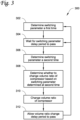
- FIG. 3 shows a flowchart of an example method 300 for controlling a compressor system according to an embodiment.
- the switching parameter is determined a first time 302.
- a delay period is allowed to pass 304.
- the switching parameter is determined a second time 306. It is determined, using the switching parameter determined at 306, whether the volume ratio of the compressor is to be changed 308.
- the volume ratio of the compressor is changed 310.
- a second delay period is allowed to pass 312 before returning to 302 or 304 and iterating method 300.
- a switching parameter is determined at 302.
- the switching parameter may be a function of the compressor suction density and the compressor speed.
- the suction density and compressor speed may be obtained according to 202 described above and shown in Figure 2 .
- the switching parameter may be determined according to 204 described above and shown in Figure 2 .
- the switching parameter delay period is a period between a first determination of the switching parameter at 302 and a second determination of the switching parameter at 306.
- the switching parameter delay period of 304 may be used to prevent excessive switching frequencies, for example by reducing the number of switching events triggered by outlier results or transient conditions (e.g. erroneous sensor readings, spikes in temperature or pressure, or the like) for suction density.
- the switching parameter delay of 304 is a period of time for an accumulating value to meet a target, for example integrating the compressor speed and suction density over time and ending the switching parameter delay period of 304 when that value meets a threshold.
- the switching parameter delay period of 304 is approximately five (5) minutes.
- the switching parameter is determined a second time 306.
- the switching parameter is determined in the same manner as at 302, including obtaining the suction density and compressor speed according to 202 and determining the switching parameter according to 204.
- the volume ratio of the compressor is changed at 310.
- the volume ratio of the compressor may be changed at 310 according to 208 described above and shown in Figure 2 .
- the method 300 includes allowing a volume ratio change delay period to pass 312.
- the volume ratio change delay period of 312 is a period between the implementation of the change to the volume ratio at 310 and determining the switching parameter for a first time at 302 in a subsequent iteration of method 300, for example, when the compressor speed and suction density values are obtained continuously.
- the volume ratio change delay period may be variable based on, for example, the number of times the volume ratio has been changed according to 310 within a predefined time period.
- the volume ratio change delay period is within a range from at or about one (1) minute to at or about one (1) hour.
- the volume ratio change delay period of 312 is approximately fifteen (15) minutes
Landscapes
- Engineering & Computer Science (AREA)
- Mechanical Engineering (AREA)
- General Engineering & Computer Science (AREA)
- Physics & Mathematics (AREA)
- Thermal Sciences (AREA)
- Computer Hardware Design (AREA)
- Fluid Mechanics (AREA)
- Control Of Positive-Displacement Pumps (AREA)
Abstract
Description
- This disclosure is directed to methods and systems for controlling valves governing the volume ratio of a variable volume ratio compressor. Particularly, this disclosure is directed to controlling the volume ratio of a compressor based on compressor mass flow, determined through inputs such as suction density and compressor speed.
- Compressors can incorporate hardware allowing the volume ratio of the compressor to be adjusted. Changing the volume ratio of a compressor affects the conditions at the discharge of the compressor. Changes to the volume ratio can affect compressor performance under partial load conditions, increasing or decreasing the efficiency of the compressor at partial and full loads depending on whether the volume ratio is properly selected for a set of operating conditions of the compressor.
- This disclosure is directed to methods and systems for controlling valves governing the volume ratio of a variable volume ratio compressor. Particularly, this disclosure is directed to controlling the volume ratio of a compressor based on compressor mass flow, determined through inputs such as suction density and compressor speed.
- Variable volume ratio compressors allow the volume ratio to be changed between at least two settings, which can improve matching of compressor discharge conditions to pressure conditions at a condenser of a refrigerant circuit that includes the compressor so as to increase efficiency.
- Under some conditions, for example when the compressor is operating close to the switching conditions, automated switching of volume ratios may occur at high frequencies. Such high-frequency switching could create additional wear on the variable volume ratio system components. Delay periods may be incorporated into determining and implementing changes to the volume ratio, providing more consistent operation over time and reducing potentially excessive changes in the volume ratio of the compressor.
- In an embodiment, a compressor system includes a variable volume ratio compressor configured to be operated at one of a plurality of different volume ratios and having a suction. The compressor system also includes a controller. The controller is configured to obtain a speed of operation of the variable volume ratio compressor and a refrigerant density at the suction of the variable volume ratio compressor. The controller is also configured to determine a switching parameter based on the speed of operation and the refrigerant density. The controller is further configured to determine whether to change a volume ratio of the variable volume ratio compressor based on a switching condition and the switching parameter. When the controller determines that the volume ratio is to be changed, the controller directs a change in the volume ratio that the variable volume ratio compressor is operated at.
- In an embodiment, the plurality of different volume ratios is two different volume ratios.
- In an embodiment, the compressor system includes one or more sensors located at the suction of the variable volume ratio compressor, and the controller obtains the refrigerant density based on outputs from the one or more sensors.
- In an embodiment, the outputs from the one or more sensors include a suction pressure and a suction temperature.
- In an embodiment, the switching parameter determined by the controller is a product of the speed of operation and the refrigerant density.
- In an embodiment, the switching condition is a linear function of the speed of operation and the refrigerant density.
- In an embodiment, the compressor system includes a piston, a first valve, and a second valve. The first valve is configured to communicate the piston with a first pressure, the second valve is configured to communicate the piston with a second pressure, different than the first pressure, and the piston is configured to be positioned by a received pressure. In an embodiment, the first pressure is a pressure at the suction of the variable volume ratio compressor and the second pressure is a pressure at an intermediate point of the variable volume ratio compressor. In an embodiment, the controller directs the change in the volume ratio that the variable volume ratio compressor is operated at by directing each of the first valve and the second valve to change positions.
- A method embodiment for controlling a variable volume ratio compressor includes obtaining a suction density and an operating speed of the variable volume ratio compressor. The method further includes determining a switching parameter based on the suction density and the operation speed. The method also includes determining whether to change a volume ratio of the variable volume ratio compressor, and changing the volume ratio of the variable volume ratio compressor when it is determined to that the volume ratio of the variable volume ratio compressor is to be changed. In an embodiment, the switching parameter is a function of a suction density of the variable-volume ratio compressor and an operation speed of the compressor.
- In an embodiment, determining the switching parameter includes determining the switching parameter at a first time, waiting a switching parameter delay period, and determining the switching parameter at a second time, and determining whether to change the volume ratio of the variable volume ratio compressor is based on the switching parameter determined at the second time. In an embodiment, the switching parameter delay period is approximately five (5) minutes.
- In an embodiment, the method includes waiting a volume ratio change delay period after changing a volume ratio of the compressor. In an embodiment, the volume ratio change delay period is approximately fifteen (15) minutes.
- In an embodiment, the switching parameter is a product of the suction density and the operating speed of the variable volume ratio compressor.
- In an embodiment, the switching condition is a linear function of the product of the suction density and the operating speed of the variable volume compressor.
- In an embodiment, changing the volume ratio of the variable volume ratio compressor includes switching the variable volume ratio compressor from a first volume ratio to a second volume ratio by changing the position of each of a first and a second valve, where the first valve is in fluid communication with a first pressure and the second valve is in fluid communication with a second pressure, different from the first pressure. In an embodiment, the first pressure is a suction pressure of the variable volume ratio compressor, and the second pressure is an intermediate pressure within the variable volume ratio compressor. In an embodiment, the first valve and the second valve are configured to provide one of either the first pressure or the second pressure to a piston within the variable volume ratio compressor.
-
-
Figure 1 shows a compressor system and a refrigerant circuit according to an embodiment. -
Figure 2 shows a flowchart of a method for controlling a compressor system according to an embodiment. -
Figure 3 shows a flowchart of an embodiment for controlling a compressor system. - This disclosure is directed to methods and systems for controlling valves governing the volume ratio of a variable volume ratio compressor. Particularly, this disclosure is directed to controlling the volume ratio of a compressor based on compressor suction density and speed.
-
Figure 1 shows acompressor system 100 according to an embodiment.Compressor system 100 includes variable-volume compressor 102, one ormore sensors 104 at ornear suction 108 ofcompressor 102, andcontroller 106.Compressor 102 is incorporated into a refrigerantcircuit including condenser 110,expansion device 112, andevaporator 114. In an embodiment,controller 106 is operatively connected tosolenoid valves compressor suction 108 orintermediate point 120 act onpiston 122 ofcompressor 102 to adjust the volume ratio ofcompressor 102. -
Compressor 102 is a variable volume compressor configured to be operated at a plurality of different volume ratios. The variablevolume ratio compressor 102 is operated at a volume ratio that may be determined bycontroller 106. The volume ratio may be changed by a variable volume ratio system. In an embodiment,compressor 102 is configured to be operated at two different volume ratios. In an embodiment,compressor 102 switches between the two volume ratios by movement ofpiston 122. In an embodiment,piston 122 is controlled by varying the pressure applied to thepiston 122 between either a suction pressure of the compressor assuction 108 or an intermediate oil pressure at anintermediate point 120 within the compressor. While the embodiment shown inFigure 1 is directed topiston 122 controlled by application of suction or intermediate pressure, it is appreciated that other variable volume ratio systems of compressors may be used. In an embodiment,compressor 102 is configured to change between different volume ratios by operation of a slide valve. In an embodiment, the volume ratio ofcompressor 102 is changed by operation of a stepper motor. In an embodiment, the volume ratio ofcompressor 102 is continuously variable across a range of volume ratio states. - The one or
more sensors 104 are configured to obtain the density of refrigerant at thesuction 108 ofcompressor 102, alone or in combination withcontroller 106. The one ormore sensors 104 may be located at or nearsuction 108 ofcompressor 102. -
Controller 106 is configured to determine a switching parameter based on the density of refrigerant atsuction 108 and the speed at whichcompressor 102 is operated.Controller 106 may obtain the density of the refrigerant, for example, from the one ormore sensors 104, or by determining the suction density from values reported by the one ormore sensors 104. The suction density is a density of the refrigerant at thesuction 108 ofcompressor 102.Controller 106 may obtain the compressor speed from a sensor included incompressor 102, or from a controller directing the operation ofcompressor 102.Controller 106 may be configured to determine the switching parameter multiple times, implement delays between determination of the switching parameter, implement delays between changing the volume ratio of the compressor and determining the switching parameter, or other such operations affecting the frequency at which volume ratio changes may be performed. The switching parameter may be a product of the suction density and the speed ofcompressor 102. -
Controller 106 is further configured to determine whether to change a volume ratio ofcompressor 102 based on the switching parameter and the switching condition. The switching condition may be, for example, a pressure ratio criterion. The pressure ratio criterion may provide a threshold value used to determine whether to switch the volume ratio ofcompressor 102. The pressure ratio criteria may be specific to components of thecompressor system 100, such ascompressor 102, and the refrigerant used in the refrigeration circuit of thecompressor system 100. In an embodiment, the pressure ratio criterion is a linear function of the product of the suction density and the compressor speed. The switching parameter may be compared to the switching condition atcontroller 106, and whether to change the volume ratio of thecompressor 102 may be determined via that comparison. -
Controller 106 is further configured to directcompressor 102 to change a volume ratio.Controller 106 may be configured todirect compressor 102 to change the volume ratio based on the switching parameter and the switching condition. In an embodiment,controller 106 is operatively connected to afirst solenoid valve 116 and asecond solenoid valve 118 and configured to direct their operation. Thefirst solenoid valve 116 may be a valve in fluid communication with the suction of the compressor and is capable of applying the pressure atsuction 108 ofcompressor 102 to thepiston 122 ofcompressor 102. Thesecond solenoid valve 118 may be a valve in fluid communication with anintermediate point 120 withincompressor 102, and capable of providing the pressure at thatintermediate point 120 to thepiston 122. The pressure atsuction 108 orintermediate point 118 drive the piston to a particular position, changing the volume ratio of thecompressor 102. Thecontroller 106 may switch thefirst solenoid valve 116 to a closed position and thesecond solenoid valve 118 to an open position, or vice versa, to switch thecompressor 102 between two different volume ratios. -
Compressor 102 may be included in a refrigerantcircuit including condenser 110,expansion device 112, andevaporator 114. Refrigerant compressed and discharged bycompressor 102 may be directed tocondenser 110, then fromcondenser 110 toexpansion device 112.Expansion device 112 is a device configured to expand and lower a pressure of a fluid, such as an expansion valve, an orifice, or the like. Refrigerant expanded atexpansion device 112 passes toevaporator 114, then returns tocompressor 102 atcompressor suction 108. The refrigerant circuit may use any refrigerant, such as, for example, refrigerant R134(a), refrigerant R1234ze(E), or any other suitable refrigerant. -
Figure 2 shows a flowchart of amethod 200 for determining when to switch a volume ratio of a compressor according to an embodiment.Method 200 includes obtaining a suction density and acompressor speed 202, determining a switching parameter based on compressor speed and suction density at 204, determining whether to switch a volume ratio of the compressor based on the switching parameter and aswitching condition 206, and changing the volume ratio of the compressor when it is determined that the volume ratio of the compressor is to be switched 208. - A suction density and the compressor speed are obtained 202. The suction density is the density of the refrigerant at the suction port of the compressor. The suction density may be obtained from one or more sensors located at or near a suction port of the compressor. The suction density may be measured directly, or computed from the outputs of the one or more sensors. In an embodiment, the suction density is computed based on a suction pressure and a suction temperature measured by sensors, and the particular refrigerant used with the compressor. For each refrigerant, the suction pressure and temperature are related to the suction density by a function specific to that refrigerant, for example due to differences in the properties of the refrigerant and its behavior as a gas. The compressor speed may be obtained from a controller of the compressor, a drive of the compressor such as a variable-frequency drive, or measured at the compressor.
- The switching parameter is determined based on the compressor speed and the
suction density 204. The switching parameter is a function of both the compressor speed and the suction density. In an embodiment, the switching parameter is a product of the compressor speed and the suction density. In an embodiment, the switching parameter is a mass flow rate. The mass flow rate may be determined based on the volume flow rate of the compressor and the suction density. - The switching parameter and a switching condition are used to determine whether to change the volume ratio of the
compressor 206. The switching condition may be, for example, a pressure ratio criterion. The pressure ratio criterion may provide a threshold value used to determine whether to switch the volume ratio of compressor. The pressure ratio criteria may be specific to the compressor, and the refrigerant used in the refrigeration circuit including the compressor. The pressure ratio criteria may be a function of the mass flow rate through the compressor. In an embodiment, the pressure ratio criterion is a linear function of the product of the suction density and the compressor speed. In an embodiment, the pressure ratio criterion is a linear function of the mass flow rate. In an embodiment, the mass flow rate is the product of the suction density and the compressor speed. In an embodiment, the mass flow rate is a product of the suction density and a volume flow rate. The switching parameter may be compared to the switching condition to determine whether to change the volume ratio of thecompressor 206 via that comparison. Themethod 200 may be used with a variety of refrigerants in variable volume ratio compressor systems. In an embodiment, the refrigerant is refrigerant 134a (R134a). In an embodiment, the refrigerant is refrigerant 513A (R513A). In an embodiment, the refrigerant is refrigerant 1234ze (R1234ze). Parameters of the function such as constants may be determined by testing compressor efficiency over states of a variable volume ratio setting of the compressor across the operating map of a particular compressor. - The volume ratio of the compressor is changed at 208 when it is determined at 206 that the volume ratio is to be changed. The volume ratio can be changed from a first volume ratio to a second volume ratio. In an embodiment, the first and second volume ratios are two of multiple volume ratios. In an embodiment, the compressor switches from one of two volume ratios to the other of the two volume ratios. In an embodiment, the switching of compressor volume ratios occurs by operating one or more valves to change a source of pressure applied to a piston of the variable volume ratio system included in the compressor. In an embodiment, the source of pressure may be switched between an intermediate oil pressure of the compressor and a suction pressure of the compressor. In an embodiment, the volume ratio of the compressor is changed at 208, for example by operation of a stepper motor or by operation of a slide valve.
- In compressor operations, the
method 200 may further include, for example, delays to avoid constant switching and to confirm when to perform switching of the volume ratio. An example of such compressor operations is provided inFigure 3 . -
Figure 3 shows a flowchart of anexample method 300 for controlling a compressor system according to an embodiment. In themethod 300 shown inFigure 3 , the switching parameter is determined afirst time 302. A delay period is allowed to pass 304. The switching parameter is determined asecond time 306. It is determined, using the switching parameter determined at 306, whether the volume ratio of the compressor is to be changed 308. When it is determined at 308 that the volume ratio of the compressor is to be changed, the volume ratio of the compressor is changed 310. After the volume ratio of the compressor is changed at 310, a second delay period is allowed to pass 312 before returning to 302 or 304 anditerating method 300. - A switching parameter is determined at 302. The switching parameter may be a function of the compressor suction density and the compressor speed. The suction density and compressor speed may be obtained according to 202 described above and shown in
Figure 2 . The switching parameter may be determined according to 204 described above and shown inFigure 2 . - After the switching parameter is determined at 302, a switching parameter delay period is allowed to pass 304. The switching parameter delay period is a period between a first determination of the switching parameter at 302 and a second determination of the switching parameter at 306. The switching parameter delay period of 304 may be used to prevent excessive switching frequencies, for example by reducing the number of switching events triggered by outlier results or transient conditions (e.g. erroneous sensor readings, spikes in temperature or pressure, or the like) for suction density. In an embodiment, the switching parameter delay of 304 is a period of time for an accumulating value to meet a target, for example integrating the compressor speed and suction density over time and ending the switching parameter delay period of 304 when that value meets a threshold. In an embodiment, the switching parameter delay period of 304 is approximately five (5) minutes.
- Once the switching parameter delay period has passed 304, the switching parameter is determined a
second time 306. The switching parameter is determined in the same manner as at 302, including obtaining the suction density and compressor speed according to 202 and determining the switching parameter according to 204. - The second determination of the switching parameter at 306 may be used to determine whether the volume ratio of the compressor is to be changed 308. Determining whether the volume ratio of the compressor is to be changed at 308 may be performed according to 206 described above and shown in
Figure 2 , comparing the switching parameter as obtained at 306 to the switching condition. - When it is determined that the volume ratio of the compressor is to be changed at 308, the volume ratio of the compressor is changed at 310. The volume ratio of the compressor may be changed at 310 according to 208 described above and shown in
Figure 2 . - Following the changing of the volume ratio at 310, the
method 300 includes allowing a volume ratio change delay period to pass 312. In an embodiment, the volume ratio change delay period of 312 is a period between the implementation of the change to the volume ratio at 310 and determining the switching parameter for a first time at 302 in a subsequent iteration ofmethod 300, for example, when the compressor speed and suction density values are obtained continuously. In an embodiment, the volume ratio change delay period may be variable based on, for example, the number of times the volume ratio has been changed according to 310 within a predefined time period. In an embodiment, the volume ratio change delay period is within a range from at or about one (1) minute to at or about one (1) hour. In an embodiment, the volume ratio change delay period of 312 is approximately fifteen (15) minutes - It is understood that any of aspects 1-9 may be combined with any of aspects 10-19.
- Aspect 1. A compressor system, comprising:
- a variable volume ratio compressor configured to be operated at one of a plurality of different volume ratios and having a suction; and
- a controller configured to:
- obtain a speed of operation of the variable volume ratio compressor and a refrigerant density at the suction of the variable volume ratio compressor;
- determine a switching parameter based on the speed of operation and the refrigerant density; determine whether to change a volume ratio of the variable volume ratio compressor based on a switching condition and the switching parameter; and
when it is determined to change the volume ratio, direct a change in the volume ratio that the variable volume ratio compressor is operated at.
- Aspect 2. The compressor system according to aspect 1, wherein the plurality of different volume ratios is two different volume ratios.
- Aspect 3. The compressor system according to any of aspects 1-2, further comprising one or more sensors located at the suction of the variable volume ratio compressor, and wherein the controller obtains the refrigerant density based on outputs from the one or more sensors.
- Aspect 4. The compressor system according to aspects 3, wherein the outputs from the one or more sensors include a suction pressure and a suction temperature.
- Aspect 5. The compressor system according to any of aspects 1-4, wherein the switching parameter determined by the controller is a product of the speed of operation and the refrigerant density.
- Aspect 6. The compressor system according to any of aspects 1-5, wherein the switching condition is a linear function of the speed of operation and the refrigerant density.
- Aspect 7. The compressor system according to any of aspects 1-6, further comprising a piston, a first valve, and a second valve, wherein the first valve is configured to control fluid communication between the piston and a first pressure source, the second valve is configured to control fluid communication between the piston and a second pressure source, different than the first pressure source, and the piston is configured to be positioned by a received pressure.
- Aspect 8. The compressor system according to aspect 7, wherein the first pressure source is the suction of the variable volume ratio compressor and the second pressure source is intermediate point of the variable volume ratio compressor.
- Aspect 9. The compressor system according to any of aspects 7-8, wherein the controller directs the change in the volume ratio that the variable volume ratio compressor by directing each of the first valve and the second valve to change positions.
- Aspect 10. A method for controlling a variable volume ratio compressor, comprising:
- obtaining a suction density and an operating speed of the variable volume ratio compressor;
- determining a switching parameter based on the suction density and the operation speed;
- determining whether to change a volume ratio of the variable volume ratio compressor based on the switching parameter and a switching condition; and
- when it is determined to change then volume ratio of the variable volume ratio compressor, changing the volume ratio of the variable volume ratio compressor,
- wherein the switching parameter is a function of a suction density of the variable-volume ratio compressor and an operation speed of the compressor.
- Aspect 11. The method according to aspect 10, wherein determining the switching parameter includes:
- determining the switching parameter at a first time;
- waiting a switching parameter delay period; and
- determining the switching parameter at a second time, and
- wherein determining whether to change the volume ratio of the variable volume ratio compressor is based on the switching parameter determined at the second time.
- Aspect 12. The method according to aspect 11, wherein the switching parameter delay period is approximately five (5) minutes.
- Aspect 13. The method according to any of aspects 10-12, further comprising waiting a volume ratio change delay period after changing a volume ratio of the compressor.
- Aspect 14. The method according to aspect 13, wherein the volume ratio change delay period is approximately fifteen (15) minutes.
- Aspect 15. The method according to any of aspects 10-14, wherein the switching parameter is a product of the suction density and the operating speed of the variable volume ratio compressor.
- Aspect 16. The method according to any of aspects 10-15, wherein the switching condition is a linear function of the product of the suction density and the operating speed of the variable volume compressor.
- Aspect 17. The method according to any of aspects 10-16, wherein changing the volume ratio of the variable volume ratio compressor includes switching the variable volume ratio compressor from a first volume ratio to a second volume ratio by changing the position of each of a first and a second valve, where the first valve is in fluid communication with a first pressure and the second valve is in fluid communication with a second pressure, different from the first pressure.
- Aspect 18. The method according to aspect 17, wherein the first pressure is a suction pressure of the variable volume ratio compressor, and the second pressure is an intermediate pressure within the variable volume ratio compressor.
- Aspect 19. The method according to any of aspects 17-18, wherein the first valve and the second valve are configured to provide one of either the first pressure or the second pressure to a piston within the variable volume ratio compressor.
- The examples disclosed in this application are to be considered in all respects as illustrative and not limitative. The scope of the invention is indicated by the appended claims rather than by the foregoing description; and all changes which come within the meaning and range of equivalency of the claims are intended to be embraced therein.
Claims (13)
- A compressor system, comprising:a variable volume ratio compressor configured to be operated at one of a plurality of different volume ratios and having a suction; anda controller configured to:determine a switching parameter, wherein the switching parameter is a mass flow rate;determine whether to change a volume ratio of the variable volume ratio compressor based on a switching condition and the switching parameter; andwhen it is determined to change the volume ratio, direct a change in the volume ratio that the variable volume ratio compressor is operated at.
- The compressor system of claim 1, wherein the controller is configured to determine the switching parameter by:determining the switching parameter at a first time;waiting a switching parameter delay period; anddetermining the switching parameter at a second time, andthe controller is configured to determine whether to change the volume ratio of the variable volume ratio compressor based on the switching parameter determined at the second time
- The compressor system of claim 1 or claim 2, further comprising a piston, a first valve, and a second valve, wherein the first valve is configured to control fluid communication between the piston and a first pressure source, the second valve is configured to control fluid communication between the piston and a second pressure source, different than the first pressure source, and the piston is configured to be positioned by a received pressure.
- The compressor system of claim 3, wherein the first pressure source is the suction of the variable volume ratio compressor and the second pressure source is an intermediate point of the variable volume ratio compressor.
- The compressor system of claim 3 or claim 4, wherein the controller directs the change in the volume ratio that the variable volume ratio compressor is operated at by directing each of the first valve and the second valve to change positions.
- The compressor system of any of claims 1-5, wherein the switching parameter is a product of a refrigerant density and a speed of operation of the variable volume ratio compressor.
- The compressor system of any of claims 1-6, wherein the switching condition is a linear function of the product of a refrigerant density and a speed of operation of the variable volume ratio compressor.
- The compressor system of any of claims 1-7, wherein operation of the variable volume ratio compressor compresses a refrigerant selected from R134a, R513a, and R1234ze.
- A method for controlling a variable volume ratio compressor, comprising:obtaining a mass flow rate;setting the mass flow rate as a switching parameter;determining whether to change a volume ratio of the variable volume ratio compressor based on the switching parameter and a switching condition; andwhen it is determined to change then volume ratio of the variable volume ratio compressor, changing the volume ratio of the variable volume ratio compressor.
- The method of claim 9, wherein determining the switching parameter includes:determining the switching parameter at a first time;waiting a switching parameter delay period; anddetermining the switching parameter at a second time, andwherein determining whether to change the volume ratio of the variable volume ratio compressor is based on the switching parameter determined at the second time.
- The method of claim 9 or claim 10, wherein the switching parameter is a product of a refrigerant density and an operating speed of the variable volume ratio compressor.
- The method of any of claims 9-11, wherein the switching condition is a linear function of the product of a refrigerant density and an operating speed of the variable volume compressor.
- The method of any of claims 9-12, wherein the refrigerant is selected from R134a, R513a, and R1234ze.
Applications Claiming Priority (2)
| Application Number | Priority Date | Filing Date | Title |
|---|---|---|---|
| US16/230,688 US10844860B2 (en) | 2018-12-21 | 2018-12-21 | Method of improved control for variable volume ratio valve |
| EP19215437.5A EP3670910B1 (en) | 2018-12-21 | 2019-12-11 | Method of improved control for variable volume ratio valve |
Related Parent Applications (1)
| Application Number | Title | Priority Date | Filing Date |
|---|---|---|---|
| EP19215437.5A Division EP3670910B1 (en) | 2018-12-21 | 2019-12-11 | Method of improved control for variable volume ratio valve |
Publications (2)
| Publication Number | Publication Date |
|---|---|
| EP4219945A1 true EP4219945A1 (en) | 2023-08-02 |
| EP4219945B1 EP4219945B1 (en) | 2025-09-24 |
Family
ID=68886965
Family Applications (2)
| Application Number | Title | Priority Date | Filing Date |
|---|---|---|---|
| EP23174738.7A Active EP4219945B1 (en) | 2018-12-21 | 2019-12-11 | Control method for variable volume ratio compressor |
| EP19215437.5A Active EP3670910B1 (en) | 2018-12-21 | 2019-12-11 | Method of improved control for variable volume ratio valve |
Family Applications After (1)
| Application Number | Title | Priority Date | Filing Date |
|---|---|---|---|
| EP19215437.5A Active EP3670910B1 (en) | 2018-12-21 | 2019-12-11 | Method of improved control for variable volume ratio valve |
Country Status (3)
| Country | Link |
|---|---|
| US (2) | US10844860B2 (en) |
| EP (2) | EP4219945B1 (en) |
| CN (2) | CN111350647B (en) |
Families Citing this family (2)
| Publication number | Priority date | Publication date | Assignee | Title |
|---|---|---|---|---|
| US11920581B2 (en) * | 2021-01-29 | 2024-03-05 | Masterflex Llc | Flow rate control for pump with flow sensor |
| CN115628216B (en) * | 2022-08-23 | 2025-11-18 | 约克(无锡)空调冷冻设备有限公司 | Compressor Control System and Control Method |
Citations (5)
| Publication number | Priority date | Publication date | Assignee | Title |
|---|---|---|---|---|
| US20060144059A1 (en) * | 2005-01-05 | 2006-07-06 | Carrier Corporation | Method and control for determining low refrigerant charge |
| US20090090118A1 (en) * | 2007-10-08 | 2009-04-09 | Emerson Climate Technologies, Inc. | Variable speed compressor protection system and method |
| US20100101248A1 (en) * | 2007-02-28 | 2010-04-29 | Carrier Corporation | Refrigerant System and Control Method |
| WO2012011374A1 (en) * | 2010-07-23 | 2012-01-26 | サンデン株式会社 | Vehicle air-conditioning device and method for determining operating state of variable capacity compressor in vehicle air-conditioning device |
| EP3348836A1 (en) * | 2017-01-17 | 2018-07-18 | General Electric Company | Two-stage reciprocating compressor optimization control system |
Family Cites Families (24)
| Publication number | Priority date | Publication date | Assignee | Title |
|---|---|---|---|---|
| US3054273A (en) * | 1959-12-28 | 1962-09-18 | Carrier Corp | Thermal expansion valve |
| JPH06341378A (en) | 1993-06-03 | 1994-12-13 | Tgk Co Ltd | Capacity control device of variable capacity compressor |
| US5715693A (en) * | 1996-07-19 | 1998-02-10 | Sunpower, Inc. | Refrigeration circuit having series evaporators and modulatable compressor |
| US6698214B2 (en) * | 2002-02-22 | 2004-03-02 | Thar Technologies, Inc | Method of refrigeration with enhanced cooling capacity and efficiency |
| JP4147891B2 (en) * | 2002-10-16 | 2008-09-10 | ダイキン工業株式会社 | Variable VI inverter screw compressor |
| US6945062B2 (en) | 2003-12-04 | 2005-09-20 | Carrier Corporation | Heat pump water heating system including a compressor having a variable clearance volume |
| CA2626884C (en) * | 2005-10-31 | 2012-01-24 | Mayekawa Mfg. Co., Ltd. | A liquid injection type screw compressor |
| WO2008094157A1 (en) * | 2007-02-02 | 2008-08-07 | Carrier Corporation | Enhanced refrigerant system |
| CN103759482B (en) * | 2007-10-31 | 2016-04-20 | 江森自控科技公司 | Control method and the gas compression system of gas compression system capacity |
| US20090277197A1 (en) | 2008-05-01 | 2009-11-12 | Gambiana Dennis S | Evaporator apparatus and method for modulating cooling |
| JP5040907B2 (en) * | 2008-09-30 | 2012-10-03 | ダイキン工業株式会社 | Refrigeration equipment |
| JP2010156499A (en) * | 2008-12-26 | 2010-07-15 | Daikin Ind Ltd | Refrigerating device |
| EP2526354B1 (en) * | 2010-01-22 | 2017-09-13 | MAHLE International GmbH | A system and a method for the flushing of air condition systems |
| JP5328713B2 (en) * | 2010-04-27 | 2013-10-30 | 三菱電機株式会社 | Refrigeration cycle equipment |
| CN103097734B (en) * | 2010-09-14 | 2016-03-23 | 江森自控科技公司 | Compressor and the method for controlling the volume ratio of compressor |
| WO2013111176A1 (en) * | 2012-01-23 | 2013-08-01 | 三菱電機株式会社 | Air-conditioning device |
| CN104204697B (en) | 2012-02-10 | 2017-02-22 | 开利公司 | Method for detection of loss of refrigerant |
| CN103573632B (en) * | 2012-08-01 | 2015-09-16 | 江森自控空调冷冻设备(无锡)有限公司 | A kind of slide valve position determination method for screw unit compressor |
| US20150093237A1 (en) | 2013-09-30 | 2015-04-02 | General Electric Company | Ceramic matrix composite component, turbine system and fabrication process |
| CN105579709B (en) * | 2013-10-01 | 2018-05-04 | 特灵国际有限公司 | Rotary compressor with variable speed and volume control |
| JP6328270B2 (en) * | 2014-12-05 | 2018-05-23 | 三菱電機株式会社 | Air conditioner |
| CN105222442A (en) * | 2015-09-17 | 2016-01-06 | 大连冰山嘉德自动化有限公司 | The control method of refrigeration that can increase work efficiency |
| CN205064274U (en) | 2015-10-15 | 2016-03-02 | 珠海格力节能环保制冷技术研究中心有限公司 | Doublestage variable volume compressor and have its air conditioning system |
| CN107917077A (en) * | 2017-12-21 | 2018-04-17 | 珠海格力电器股份有限公司 | Compressor, control method and air conditioning equipment |
-
2018
- 2018-12-21 US US16/230,688 patent/US10844860B2/en active Active
-
2019
- 2019-12-11 EP EP23174738.7A patent/EP4219945B1/en active Active
- 2019-12-11 EP EP19215437.5A patent/EP3670910B1/en active Active
- 2019-12-20 CN CN201911325276.6A patent/CN111350647B/en active Active
- 2019-12-20 CN CN202310921108.3A patent/CN116951799A/en active Pending
-
2020
- 2020-11-23 US US17/101,936 patent/US11725661B2/en active Active
Patent Citations (5)
| Publication number | Priority date | Publication date | Assignee | Title |
|---|---|---|---|---|
| US20060144059A1 (en) * | 2005-01-05 | 2006-07-06 | Carrier Corporation | Method and control for determining low refrigerant charge |
| US20100101248A1 (en) * | 2007-02-28 | 2010-04-29 | Carrier Corporation | Refrigerant System and Control Method |
| US20090090118A1 (en) * | 2007-10-08 | 2009-04-09 | Emerson Climate Technologies, Inc. | Variable speed compressor protection system and method |
| WO2012011374A1 (en) * | 2010-07-23 | 2012-01-26 | サンデン株式会社 | Vehicle air-conditioning device and method for determining operating state of variable capacity compressor in vehicle air-conditioning device |
| EP3348836A1 (en) * | 2017-01-17 | 2018-07-18 | General Electric Company | Two-stage reciprocating compressor optimization control system |
Also Published As
| Publication number | Publication date |
|---|---|
| US20210180598A1 (en) | 2021-06-17 |
| EP4219945B1 (en) | 2025-09-24 |
| US10844860B2 (en) | 2020-11-24 |
| US11725661B2 (en) | 2023-08-15 |
| CN111350647A (en) | 2020-06-30 |
| EP3670910A1 (en) | 2020-06-24 |
| CN111350647B (en) | 2023-08-08 |
| US20200200175A1 (en) | 2020-06-25 |
| EP3670910B1 (en) | 2023-05-24 |
| CN116951799A (en) | 2023-10-27 |
Similar Documents
| Publication | Publication Date | Title |
|---|---|---|
| US10001309B2 (en) | Air-conditioning apparatus | |
| CN111630331B (en) | Refrigeration cycle device | |
| EP3415842B1 (en) | Compressor control for increased efficiency | |
| JP4403300B2 (en) | Refrigeration equipment | |
| US11725661B2 (en) | Method of improved control for variable volume ratio valve | |
| US9989943B2 (en) | HVAC systems and controls | |
| EP3339762A1 (en) | Air conditioner | |
| US20150316297A1 (en) | A method for matching refrigeration load to compressor capacity | |
| KR102038538B1 (en) | A device for discharging refrigerant of a crank room in a swash plate type compressor | |
| KR940018635A (en) | Refrigeration cycle unit | |
| EP3475632A1 (en) | A method for controlling pressure and oil level in an oil receiver of a vapour compressions system | |
| EP2918947B1 (en) | Air conditioner | |
| US12215905B2 (en) | Air conditioning apparatus | |
| CN109186042B (en) | Defrosting method for air conditioner | |
| KR100537337B1 (en) | Method for Setting Initial Open Value of Multi Type Air-conditioner using Electronic Expansion Valve | |
| KR102015317B1 (en) | A Variable displacement swash plate type compressor | |
| KR20130096963A (en) | A refrigerator and the method of the refrigerator | |
| KR102013595B1 (en) | A Variable displacement swash plate type compressor and method for controlling thereof | |
| KR101579099B1 (en) | Air conditioner | |
| US9982928B2 (en) | Method for controlling a compressor of a refrigeration system comprising a motor, and a compressor of a refrigeration system | |
| KR20180109598A (en) | control apparatis for refrigerator and control method using thereof | |
| JP2001116372A (en) | Refrigerating cycle controller | |
| JPWO2023148862A5 (en) | ||
| JP2020046089A (en) | Control device, temperature adjustment device and control method | |
| KR20090068969A (en) | Air conditioning system |
Legal Events
| Date | Code | Title | Description |
|---|---|---|---|
| PUAI | Public reference made under article 153(3) epc to a published international application that has entered the european phase |
Free format text: ORIGINAL CODE: 0009012 |
|
| STAA | Information on the status of an ep patent application or granted ep patent |
Free format text: STATUS: THE APPLICATION HAS BEEN PUBLISHED |
|
| AC | Divisional application: reference to earlier application |
Ref document number: 3670910 Country of ref document: EP Kind code of ref document: P |
|
| AK | Designated contracting states |
Kind code of ref document: A1 Designated state(s): AL AT BE BG CH CY CZ DE DK EE ES FI FR GB GR HR HU IE IS IT LI LT LU LV MC MK MT NL NO PL PT RO RS SE SI SK SM TR |
|
| STAA | Information on the status of an ep patent application or granted ep patent |
Free format text: STATUS: REQUEST FOR EXAMINATION WAS MADE |
|
| P01 | Opt-out of the competence of the unified patent court (upc) registered |
Effective date: 20240112 |
|
| 17P | Request for examination filed |
Effective date: 20240131 |
|
| RBV | Designated contracting states (corrected) |
Designated state(s): AL AT BE BG CH CY CZ DE DK EE ES FI FR GB GR HR HU IE IS IT LI LT LU LV MC MK MT NL NO PL PT RO RS SE SI SK SM TR |
|
| GRAP | Despatch of communication of intention to grant a patent |
Free format text: ORIGINAL CODE: EPIDOSNIGR1 |
|
| STAA | Information on the status of an ep patent application or granted ep patent |
Free format text: STATUS: GRANT OF PATENT IS INTENDED |
|
| INTG | Intention to grant announced |
Effective date: 20250415 |
|
| GRAS | Grant fee paid |
Free format text: ORIGINAL CODE: EPIDOSNIGR3 |
|
| GRAA | (expected) grant |
Free format text: ORIGINAL CODE: 0009210 |
|
| STAA | Information on the status of an ep patent application or granted ep patent |
Free format text: STATUS: THE PATENT HAS BEEN GRANTED |
|
| AC | Divisional application: reference to earlier application |
Ref document number: 3670910 Country of ref document: EP Kind code of ref document: P |
|
| AK | Designated contracting states |
Kind code of ref document: B1 Designated state(s): AL AT BE BG CH CY CZ DE DK EE ES FI FR GB GR HR HU IE IS IT LI LT LU LV MC MK MT NL NO PL PT RO RS SE SI SK SM TR |
|
| REG | Reference to a national code |
Ref country code: GB Ref legal event code: FG4D |
|
| REG | Reference to a national code |
Ref country code: CH Ref legal event code: EP |
|
| REG | Reference to a national code |
Ref country code: DE Ref legal event code: R096 Ref document number: 602019076270 Country of ref document: DE |
|
| REG | Reference to a national code |
Ref country code: IE Ref legal event code: FG4D |
|
| PGFP | Annual fee paid to national office [announced via postgrant information from national office to epo] |
Ref country code: DE Payment date: 20251126 Year of fee payment: 7 |
|
| PGFP | Annual fee paid to national office [announced via postgrant information from national office to epo] |
Ref country code: GB Payment date: 20251119 Year of fee payment: 7 |
|
| PG25 | Lapsed in a contracting state [announced via postgrant information from national office to epo] |
Ref country code: NO Free format text: LAPSE BECAUSE OF FAILURE TO SUBMIT A TRANSLATION OF THE DESCRIPTION OR TO PAY THE FEE WITHIN THE PRESCRIBED TIME-LIMIT Effective date: 20251224 |
|
| REG | Reference to a national code |
Ref country code: LT Ref legal event code: MG9D |
|
| PG25 | Lapsed in a contracting state [announced via postgrant information from national office to epo] |
Ref country code: FI Free format text: LAPSE BECAUSE OF FAILURE TO SUBMIT A TRANSLATION OF THE DESCRIPTION OR TO PAY THE FEE WITHIN THE PRESCRIBED TIME-LIMIT Effective date: 20250924 |
|
| PG25 | Lapsed in a contracting state [announced via postgrant information from national office to epo] |
Ref country code: HR Free format text: LAPSE BECAUSE OF FAILURE TO SUBMIT A TRANSLATION OF THE DESCRIPTION OR TO PAY THE FEE WITHIN THE PRESCRIBED TIME-LIMIT Effective date: 20250924 |
|
| PGFP | Annual fee paid to national office [announced via postgrant information from national office to epo] |
Ref country code: FR Payment date: 20251120 Year of fee payment: 7 |
|
| PG25 | Lapsed in a contracting state [announced via postgrant information from national office to epo] |
Ref country code: GR Free format text: LAPSE BECAUSE OF FAILURE TO SUBMIT A TRANSLATION OF THE DESCRIPTION OR TO PAY THE FEE WITHIN THE PRESCRIBED TIME-LIMIT Effective date: 20251225 |
|
| PG25 | Lapsed in a contracting state [announced via postgrant information from national office to epo] |
Ref country code: SE Free format text: LAPSE BECAUSE OF FAILURE TO SUBMIT A TRANSLATION OF THE DESCRIPTION OR TO PAY THE FEE WITHIN THE PRESCRIBED TIME-LIMIT Effective date: 20250924 |
|
| PG25 | Lapsed in a contracting state [announced via postgrant information from national office to epo] |
Ref country code: LV Free format text: LAPSE BECAUSE OF FAILURE TO SUBMIT A TRANSLATION OF THE DESCRIPTION OR TO PAY THE FEE WITHIN THE PRESCRIBED TIME-LIMIT Effective date: 20250924 |
|
| PG25 | Lapsed in a contracting state [announced via postgrant information from national office to epo] |
Ref country code: BG Free format text: LAPSE BECAUSE OF FAILURE TO SUBMIT A TRANSLATION OF THE DESCRIPTION OR TO PAY THE FEE WITHIN THE PRESCRIBED TIME-LIMIT Effective date: 20250924 |
|
| PG25 | Lapsed in a contracting state [announced via postgrant information from national office to epo] |
Ref country code: RS Free format text: LAPSE BECAUSE OF FAILURE TO SUBMIT A TRANSLATION OF THE DESCRIPTION OR TO PAY THE FEE WITHIN THE PRESCRIBED TIME-LIMIT Effective date: 20251224 |
|
| REG | Reference to a national code |
Ref country code: NL Ref legal event code: MP Effective date: 20250924 |
|
| PG25 | Lapsed in a contracting state [announced via postgrant information from national office to epo] |
Ref country code: NL Free format text: LAPSE BECAUSE OF FAILURE TO SUBMIT A TRANSLATION OF THE DESCRIPTION OR TO PAY THE FEE WITHIN THE PRESCRIBED TIME-LIMIT Effective date: 20250924 |
|
| REG | Reference to a national code |
Ref country code: AT Ref legal event code: MK05 Ref document number: 1840515 Country of ref document: AT Kind code of ref document: T Effective date: 20250924 |
|
| PG25 | Lapsed in a contracting state [announced via postgrant information from national office to epo] |
Ref country code: SM Free format text: LAPSE BECAUSE OF FAILURE TO SUBMIT A TRANSLATION OF THE DESCRIPTION OR TO PAY THE FEE WITHIN THE PRESCRIBED TIME-LIMIT Effective date: 20250924 |
|
| PG25 | Lapsed in a contracting state [announced via postgrant information from national office to epo] |
Ref country code: ES Free format text: LAPSE BECAUSE OF FAILURE TO SUBMIT A TRANSLATION OF THE DESCRIPTION OR TO PAY THE FEE WITHIN THE PRESCRIBED TIME-LIMIT Effective date: 20250924 |
|
| PG25 | Lapsed in a contracting state [announced via postgrant information from national office to epo] |
Ref country code: AT Free format text: LAPSE BECAUSE OF FAILURE TO SUBMIT A TRANSLATION OF THE DESCRIPTION OR TO PAY THE FEE WITHIN THE PRESCRIBED TIME-LIMIT Effective date: 20250924 |
|
| PG25 | Lapsed in a contracting state [announced via postgrant information from national office to epo] |
Ref country code: IT Free format text: LAPSE BECAUSE OF FAILURE TO SUBMIT A TRANSLATION OF THE DESCRIPTION OR TO PAY THE FEE WITHIN THE PRESCRIBED TIME-LIMIT Effective date: 20250924 Ref country code: RO Free format text: LAPSE BECAUSE OF FAILURE TO SUBMIT A TRANSLATION OF THE DESCRIPTION OR TO PAY THE FEE WITHIN THE PRESCRIBED TIME-LIMIT Effective date: 20250924 |
|
| PG25 | Lapsed in a contracting state [announced via postgrant information from national office to epo] |
Ref country code: IS Free format text: LAPSE BECAUSE OF FAILURE TO SUBMIT A TRANSLATION OF THE DESCRIPTION OR TO PAY THE FEE WITHIN THE PRESCRIBED TIME-LIMIT Effective date: 20260124 |
|
| PG25 | Lapsed in a contracting state [announced via postgrant information from national office to epo] |
Ref country code: PT Free format text: LAPSE BECAUSE OF FAILURE TO SUBMIT A TRANSLATION OF THE DESCRIPTION OR TO PAY THE FEE WITHIN THE PRESCRIBED TIME-LIMIT Effective date: 20260126 Ref country code: CZ Free format text: LAPSE BECAUSE OF FAILURE TO SUBMIT A TRANSLATION OF THE DESCRIPTION OR TO PAY THE FEE WITHIN THE PRESCRIBED TIME-LIMIT Effective date: 20250924 |
|
| PG25 | Lapsed in a contracting state [announced via postgrant information from national office to epo] |
Ref country code: PL Free format text: LAPSE BECAUSE OF FAILURE TO SUBMIT A TRANSLATION OF THE DESCRIPTION OR TO PAY THE FEE WITHIN THE PRESCRIBED TIME-LIMIT Effective date: 20250924 |
|
| PG25 | Lapsed in a contracting state [announced via postgrant information from national office to epo] |
Ref country code: SK Free format text: LAPSE BECAUSE OF FAILURE TO SUBMIT A TRANSLATION OF THE DESCRIPTION OR TO PAY THE FEE WITHIN THE PRESCRIBED TIME-LIMIT Effective date: 20250924 Ref country code: EE Free format text: LAPSE BECAUSE OF FAILURE TO SUBMIT A TRANSLATION OF THE DESCRIPTION OR TO PAY THE FEE WITHIN THE PRESCRIBED TIME-LIMIT Effective date: 20250924 |