EP4219407B1 - System and method for improving water quality of dehydrating tower of purified terephthalic acid apparatus - Google Patents
System and method for improving water quality of dehydrating tower of purified terephthalic acid apparatus Download PDFInfo
- Publication number
- EP4219407B1 EP4219407B1 EP22736133.4A EP22736133A EP4219407B1 EP 4219407 B1 EP4219407 B1 EP 4219407B1 EP 22736133 A EP22736133 A EP 22736133A EP 4219407 B1 EP4219407 B1 EP 4219407B1
- Authority
- EP
- European Patent Office
- Prior art keywords
- tail gas
- condensed liquid
- vapor
- washing
- stage
- Prior art date
- Legal status (The legal status is an assumption and is not a legal conclusion. Google has not performed a legal analysis and makes no representation as to the accuracy of the status listed.)
- Active
Links
Images

Classifications
-
- B—PERFORMING OPERATIONS; TRANSPORTING
- B01—PHYSICAL OR CHEMICAL PROCESSES OR APPARATUS IN GENERAL
- B01D—SEPARATION
- B01D1/00—Evaporating
- B01D1/26—Multiple-effect evaporating
-
- B—PERFORMING OPERATIONS; TRANSPORTING
- B01—PHYSICAL OR CHEMICAL PROCESSES OR APPARATUS IN GENERAL
- B01D—SEPARATION
- B01D53/00—Separation of gases or vapours; Recovering vapours of volatile solvents from gases; Chemical or biological purification of waste gases, e.g. engine exhaust gases, smoke, fumes, flue gases, aerosols
- B01D53/26—Drying gases or vapours
- B01D53/265—Drying gases or vapours by refrigeration (condensation)
-
- B—PERFORMING OPERATIONS; TRANSPORTING
- B01—PHYSICAL OR CHEMICAL PROCESSES OR APPARATUS IN GENERAL
- B01D—SEPARATION
- B01D5/00—Condensation of vapours; Recovering volatile solvents by condensation
- B01D5/0033—Other features
- B01D5/0036—Multiple-effect condensation; Fractional condensation
-
- B—PERFORMING OPERATIONS; TRANSPORTING
- B01—PHYSICAL OR CHEMICAL PROCESSES OR APPARATUS IN GENERAL
- B01D—SEPARATION
- B01D5/00—Condensation of vapours; Recovering volatile solvents by condensation
- B01D5/0033—Other features
- B01D5/0039—Recuperation of heat, e.g. use of heat pump(s), compression
-
- B—PERFORMING OPERATIONS; TRANSPORTING
- B01—PHYSICAL OR CHEMICAL PROCESSES OR APPARATUS IN GENERAL
- B01D—SEPARATION
- B01D5/00—Condensation of vapours; Recovering volatile solvents by condensation
- B01D5/0033—Other features
- B01D5/0054—General arrangements, e.g. flow sheets
-
- B—PERFORMING OPERATIONS; TRANSPORTING
- B01—PHYSICAL OR CHEMICAL PROCESSES OR APPARATUS IN GENERAL
- B01D—SEPARATION
- B01D5/00—Condensation of vapours; Recovering volatile solvents by condensation
- B01D5/0057—Condensation of vapours; Recovering volatile solvents by condensation in combination with other processes
- B01D5/006—Condensation of vapours; Recovering volatile solvents by condensation in combination with other processes with evaporation or distillation
-
- B—PERFORMING OPERATIONS; TRANSPORTING
- B01—PHYSICAL OR CHEMICAL PROCESSES OR APPARATUS IN GENERAL
- B01D—SEPARATION
- B01D53/00—Separation of gases or vapours; Recovering vapours of volatile solvents from gases; Chemical or biological purification of waste gases, e.g. engine exhaust gases, smoke, fumes, flue gases, aerosols
- B01D53/002—Separation of gases or vapours; Recovering vapours of volatile solvents from gases; Chemical or biological purification of waste gases, e.g. engine exhaust gases, smoke, fumes, flue gases, aerosols by condensation
-
- B—PERFORMING OPERATIONS; TRANSPORTING
- B01—PHYSICAL OR CHEMICAL PROCESSES OR APPARATUS IN GENERAL
- B01D—SEPARATION
- B01D53/00—Separation of gases or vapours; Recovering vapours of volatile solvents from gases; Chemical or biological purification of waste gases, e.g. engine exhaust gases, smoke, fumes, flue gases, aerosols
- B01D53/14—Separation of gases or vapours; Recovering vapours of volatile solvents from gases; Chemical or biological purification of waste gases, e.g. engine exhaust gases, smoke, fumes, flue gases, aerosols by absorption
- B01D53/1406—Multiple stage absorption
-
- B—PERFORMING OPERATIONS; TRANSPORTING
- B01—PHYSICAL OR CHEMICAL PROCESSES OR APPARATUS IN GENERAL
- B01D—SEPARATION
- B01D53/00—Separation of gases or vapours; Recovering vapours of volatile solvents from gases; Chemical or biological purification of waste gases, e.g. engine exhaust gases, smoke, fumes, flue gases, aerosols
- B01D53/14—Separation of gases or vapours; Recovering vapours of volatile solvents from gases; Chemical or biological purification of waste gases, e.g. engine exhaust gases, smoke, fumes, flue gases, aerosols by absorption
- B01D53/1456—Removing acid components
-
- B—PERFORMING OPERATIONS; TRANSPORTING
- B01—PHYSICAL OR CHEMICAL PROCESSES OR APPARATUS IN GENERAL
- B01D—SEPARATION
- B01D53/00—Separation of gases or vapours; Recovering vapours of volatile solvents from gases; Chemical or biological purification of waste gases, e.g. engine exhaust gases, smoke, fumes, flue gases, aerosols
- B01D53/14—Separation of gases or vapours; Recovering vapours of volatile solvents from gases; Chemical or biological purification of waste gases, e.g. engine exhaust gases, smoke, fumes, flue gases, aerosols by absorption
- B01D53/1487—Removing organic compounds
-
- B—PERFORMING OPERATIONS; TRANSPORTING
- B01—PHYSICAL OR CHEMICAL PROCESSES OR APPARATUS IN GENERAL
- B01D—SEPARATION
- B01D53/00—Separation of gases or vapours; Recovering vapours of volatile solvents from gases; Chemical or biological purification of waste gases, e.g. engine exhaust gases, smoke, fumes, flue gases, aerosols
- B01D53/14—Separation of gases or vapours; Recovering vapours of volatile solvents from gases; Chemical or biological purification of waste gases, e.g. engine exhaust gases, smoke, fumes, flue gases, aerosols by absorption
- B01D53/18—Absorbing units; Liquid distributors therefor
-
- C—CHEMISTRY; METALLURGY
- C02—TREATMENT OF WATER, WASTE WATER, SEWAGE, OR SLUDGE
- C02F—TREATMENT OF WATER, WASTE WATER, SEWAGE, OR SLUDGE
- C02F1/00—Treatment of water, waste water, or sewage
- C02F1/02—Treatment of water, waste water, or sewage by heating
- C02F1/04—Treatment of water, waste water, or sewage by heating by distillation or evaporation
- C02F1/048—Purification of waste water by evaporation
-
- C—CHEMISTRY; METALLURGY
- C02—TREATMENT OF WATER, WASTE WATER, SEWAGE, OR SLUDGE
- C02F—TREATMENT OF WATER, WASTE WATER, SEWAGE, OR SLUDGE
- C02F1/00—Treatment of water, waste water, or sewage
- C02F1/02—Treatment of water, waste water, or sewage by heating
- C02F1/04—Treatment of water, waste water, or sewage by heating by distillation or evaporation
- C02F1/16—Treatment of water, waste water, or sewage by heating by distillation or evaporation using waste heat from other processes
-
- C—CHEMISTRY; METALLURGY
- C07—ORGANIC CHEMISTRY
- C07C—ACYCLIC OR CARBOCYCLIC COMPOUNDS
- C07C51/00—Preparation of carboxylic acids or their salts, halides or anhydrides
- C07C51/16—Preparation of carboxylic acids or their salts, halides or anhydrides by oxidation
- C07C51/21—Preparation of carboxylic acids or their salts, halides or anhydrides by oxidation with molecular oxygen
- C07C51/255—Preparation of carboxylic acids or their salts, halides or anhydrides by oxidation with molecular oxygen of compounds containing six-membered aromatic rings without ring-splitting
- C07C51/265—Preparation of carboxylic acids or their salts, halides or anhydrides by oxidation with molecular oxygen of compounds containing six-membered aromatic rings without ring-splitting having alkyl side chains which are oxidised to carboxyl groups
-
- C—CHEMISTRY; METALLURGY
- C07—ORGANIC CHEMISTRY
- C07C—ACYCLIC OR CARBOCYCLIC COMPOUNDS
- C07C51/00—Preparation of carboxylic acids or their salts, halides or anhydrides
- C07C51/42—Separation; Purification; Stabilisation; Use of additives
-
- F—MECHANICAL ENGINEERING; LIGHTING; HEATING; WEAPONS; BLASTING
- F28—HEAT EXCHANGE IN GENERAL
- F28B—STEAM OR VAPOUR CONDENSERS
- F28B7/00—Combinations of two or more condensers, e.g. provision of reserve condenser
-
- F—MECHANICAL ENGINEERING; LIGHTING; HEATING; WEAPONS; BLASTING
- F28—HEAT EXCHANGE IN GENERAL
- F28D—HEAT-EXCHANGE APPARATUS, NOT PROVIDED FOR IN ANOTHER SUBCLASS, IN WHICH THE HEAT-EXCHANGE MEDIA DO NOT COME INTO DIRECT CONTACT
- F28D21/00—Heat-exchange apparatus not covered by any of the groups F28D1/00 - F28D20/00
-
- B—PERFORMING OPERATIONS; TRANSPORTING
- B01—PHYSICAL OR CHEMICAL PROCESSES OR APPARATUS IN GENERAL
- B01D—SEPARATION
- B01D2252/00—Absorbents, i.e. solvents and liquid materials for gas absorption
- B01D2252/10—Inorganic absorbents
- B01D2252/103—Water
-
- B—PERFORMING OPERATIONS; TRANSPORTING
- B01—PHYSICAL OR CHEMICAL PROCESSES OR APPARATUS IN GENERAL
- B01D—SEPARATION
- B01D2252/00—Absorbents, i.e. solvents and liquid materials for gas absorption
- B01D2252/20—Organic absorbents
-
- B—PERFORMING OPERATIONS; TRANSPORTING
- B01—PHYSICAL OR CHEMICAL PROCESSES OR APPARATUS IN GENERAL
- B01D—SEPARATION
- B01D2257/00—Components to be removed
- B01D2257/70—Organic compounds not provided for in groups B01D2257/00 - B01D2257/602
- B01D2257/702—Hydrocarbons
- B01D2257/7027—Aromatic hydrocarbons
-
- B—PERFORMING OPERATIONS; TRANSPORTING
- B01—PHYSICAL OR CHEMICAL PROCESSES OR APPARATUS IN GENERAL
- B01D—SEPARATION
- B01D2259/00—Type of treatment
- B01D2259/65—Employing advanced heat integration, e.g. Pinch technology
-
- C—CHEMISTRY; METALLURGY
- C02—TREATMENT OF WATER, WASTE WATER, SEWAGE, OR SLUDGE
- C02F—TREATMENT OF WATER, WASTE WATER, SEWAGE, OR SLUDGE
- C02F2103/00—Nature of the water, waste water, sewage or sludge to be treated
- C02F2103/18—Nature of the water, waste water, sewage or sludge to be treated from the purification of gaseous effluents
-
- C—CHEMISTRY; METALLURGY
- C02—TREATMENT OF WATER, WASTE WATER, SEWAGE, OR SLUDGE
- C02F—TREATMENT OF WATER, WASTE WATER, SEWAGE, OR SLUDGE
- C02F2103/00—Nature of the water, waste water, sewage or sludge to be treated
- C02F2103/34—Nature of the water, waste water, sewage or sludge to be treated from industrial activities not provided for in groups C02F2103/12 - C02F2103/32
- C02F2103/36—Nature of the water, waste water, sewage or sludge to be treated from industrial activities not provided for in groups C02F2103/12 - C02F2103/32 from the manufacture of organic compounds
-
- C—CHEMISTRY; METALLURGY
- C02—TREATMENT OF WATER, WASTE WATER, SEWAGE, OR SLUDGE
- C02F—TREATMENT OF WATER, WASTE WATER, SEWAGE, OR SLUDGE
- C02F2301/00—General aspects of water treatment
- C02F2301/04—Flow arrangements
-
- C—CHEMISTRY; METALLURGY
- C02—TREATMENT OF WATER, WASTE WATER, SEWAGE, OR SLUDGE
- C02F—TREATMENT OF WATER, WASTE WATER, SEWAGE, OR SLUDGE
- C02F2301/00—General aspects of water treatment
- C02F2301/08—Multistage treatments, e.g. repetition of the same process step under different conditions
-
- C—CHEMISTRY; METALLURGY
- C02—TREATMENT OF WATER, WASTE WATER, SEWAGE, OR SLUDGE
- C02F—TREATMENT OF WATER, WASTE WATER, SEWAGE, OR SLUDGE
- C02F2303/00—Specific treatment goals
- C02F2303/10—Energy recovery
Definitions
- the present disclosure relates to a treatment method for improving the water quality of a dehydration tower in a purified terephthalic acid device, in particular to a system and process method for purifying and utilizing a condensed liquid of oxidized tail gas during the industrial production of PTA.
- a condensed liquid of tail gas is produced.
- the condensed liquid of the tail gas is purified generally by extraction: a refined mother liquor (condensed liquid) of a PTA refining unit is heated with medium-pressure vapor and then enters an extraction tower together with an extractant, namely, p-xylene (PX for short, hereinafter referred to as PX) to be extracted, and the extractant PX extracts solutes (organic components such as acetic acid, p-toluic (PT) acid and the like) in an original solvent into the PX to form a PX extraction phase, wherein the PX extraction phase is returned to an oxidation reactor to continue to react, a raffinate phase (the refined mother liquor after separation of the acetic acid, the PT acid and other organic components in the original solvent) is rectified by a traditional dehydration tower to exchange water with the acetic acid, acetic acid vapor
- the present invention provides a system for improving the water quality of a dehydration tower in a purified terephthalic acid device according to claims 1 to 3 and a process for improving the water quality of a dehydration tower in a purified terephthalic acid device according to claims 4 and 5. Through the system and the corresponding process, a purification or enrichment effect is achieved.
- a treatment system for improving the water quality of a dehydration tower in a purified terephthalic acid device including a dehydration washing device, a tail gas condensation device communicating with the top of the dehydration washing device, and a water separation device communicating with the tail gas condensation device, wherein
- the dehydration washing device is a dehydration washing tower, the bottom of the dehydration washing tower communicates with a PTA oxidation reactor, and a concentrated reaction liquid after washing is returned to the oxidation reactor to continue to react, wherein a circulating pump may be used.
- first-stage purified water washing unit, the second-stage concentrated water washing unit and the third-stage refined mother liquor washing unit are respectively provided with spray heads to wash tail gas by spraying.
- the first oxidized tail gas condensation system includes 1-4, preferably 3 stages of oxidized tail gas condensers,
- the second oxidized tail gas condensation system includes 1-4, preferably 3 stages of oxidized tail gas condensers.
- the water separation device is a water separation tower, evaporation units for purifying condensed water are disposed in a tower body, a final-effect condensation unit is disposed below the evaporation units, and a vacuum pump is connected to the bottom of the final-effect condensation unit.
- the water separation tower may be a water separation tower based on falling film evaporation or rising film evaporation.
- the evaporation units include a first-effect evaporation unit and a second-effect evaporation unit
- the first-effect evaporation unit includes a second condensed liquid inlet and a first heat exchange chamber, an upper portion of the first heat exchange chamber is connected with a first vapor passage for a vapor phase to enter a next effect evaporation unit and a first downcomer for a liquid phase to flow to a next effect evaporation unit, and the bottom of the first downcomer is provided with a first concentric-square-shaped device
- the second-effect evaporation unit includes a second heat exchange chamber, an upper portion of the second heat exchange chamber is provided with a second vapor passage for a vapor phase to pass through after heat exchange of the condensed water and a second downcomer for a liquid phase to pass through, and the bottom of the second downcomer is provided with a second concentric-square-shaped device
- a lower portion of the second heat exchange chamber is provided with a first condensed liquid
- a method for improving the water quality of a dehydration tower in a purified terephthalic acid device including the following steps:
- the present disclosure has the following beneficial effects: 1) in the present disclosure, an extraction technology is replaced with a water separation tower technology, which saves medium-pressure vapor required for extraction, reduces the consumption of external vapor per ton of product by about 0.2 tons or above, greatly reduces the energy consumption, and achieves the remarkable economic benefit; 2) the tail gas condensation device only needs to use low-pressure vapor of about 0.05 MPa (G) produced by an N m -th-stage condenser (one or more stages in N i+1 -th to N-th-stage condensers) as a heating medium, which may greatly reduce low-grade vapor entering a steam turbine of an air compressor system and reduce the burden on an air compressor (a four-in-one unit); and in addition, the difficulty of designing and manufacturing an air compressor unit is lowered, the manufacturing cost is greatly reduced, and the loss of a cold source in the four-in-one unit and the amount of circulating cooling water are reduced; 3) the water separation tower is a tower-type multi-effect evaporation water separation
- a dotted box shows an oxidation reactor (01) for producing PTA.
- PT and air are introduced into the oxidation reactor (01) in which there are acetic acid and the like, a reaction is performed to obtain a reaction liquid, and the reaction liquid is subjected to procedures of washing and the like to obtain a reactant and a refined mother liquor.
- the refined mother liquor contains a large amount of organic components such as the acetic acid, PT acid and the like, so that in a treatment system provided by the present disclosure, the refined mother liquor is used as a spraying liquid of a third-stage refined mother liquor washing unit.
- reaction tail gas the reaction liquid
- a treatment system for improving the water quality of a dehydration tower in a purified terephthalic acid device including a dehydration washing device 1, a tail gas condensation device 2 communicating with the top of the dehydration washing device 1 and a water separation device 3 communicating with the tail gas condensation device 2.
- the dehydration washing device 1 includes a first-stage purified water washing unit 11 located at the top of the dehydration washing device, a second-stage concentrated water washing unit 12 located in the middle of the dehydration washing device and a third-stage refined mother liquor washing unit 13 located at a lower portion of the dehydration washing device, and each of the units is washed by spraying.
- the reaction tail gas After coming out from the bottom of the oxidation reactor (01), the reaction tail gas is introduced into the dehydration washing device 1, and an introduction inlet is formed in a lower portion of the third-stage refined mother liquor washing unit 13.
- the reaction tail gas firstly passes through the third-stage refined mother liquor washing unit 13 to be subjected to spray washing with the refined mother liquor, then passes through the second-stage concentrated water washing unit 12 to be subjected to spray washing with concentrated water, and finally passes through the first-stage purified water washing unit 11 to be subjected to spray washing with purified water.
- the dehydration washing device is a dehydration washing tower, the bottom of the dehydration washing tower communicates with the PTA oxidation reactor, and a concentrated reaction liquid (in which a large amount of the organic components such as the acetic acid, the PT acid and the like are enriched) after washing is returned to the oxidation reactor to continue to react, wherein the circulating pump may be used 14.
- the tail gas condensation device 2 includes a first oxidized tail gas condensation system 21 including one or more stages of oxidized tail gas condensers that communicate in sequence and a second oxidized tail gas condensation system 22 located after the first oxidized tail gas condensation system 21 and including one or more stages of oxidized tail gas condensers that communicate in sequence, each stage of the oxidized tail gas condenser in the first oxidized tail gas condensation system 21 communicates to a first high-temperature condensed liquid tank 4 for containing a first condensed liquid obtained after heat exchange by the oxidized tail gas condensers in the system, and each stage of the oxidized tail gas condenser in the second oxidized tail gas condensation system 22 communicates to a second condensed liquid tank 5 for containing a second condensed liquid obtained after heat exchange by the oxidized tail gas condensers in the system and a second vapor channel for exporting vapor, wherein the oxidized tail gas condenser disposed at a tail end is provided with a tail
- the first oxidized tail gas condensation system 21 includes 1-N, preferably 3 stages of oxidized tail gas condensers.
- FIG. 1 shows two stages of oxidized tail gas condensers. Each stage of oxidized tail gas condenser is provided with a cold water inlet 211 and a hot water outlet 212.
- reaction tail gas washed with the dehydration tower firstly enters a first-stage oxidized tail gas condenser and then enters other oxidized tail gas condensers backwards in sequence.
- the reaction tail gas will exchange heat with cold water flowing in from the cold water inlet 211. After heat exchange, the cold water is heated, and the reaction tail gas in the oxidized tail gas condensers will be cooled, so that a part of the reaction tail gas will become a condensed liquid, namely, a first condensed liquid.
- the first condensed liquid produced by each stage of oxidized tail gas condenser will flow into the first high-temperature condensed liquid tank 4 through a pipeline.
- the reaction tail gas After being condensed through the first oxidized tail gas condensation system 21, the reaction tail gas enters the second oxidized tail gas condensation system 22 to continue to be condensed, and through the condensation treatment of the first oxidized tail gas condensation system 21, the temperature of the reaction tail gas and the pressure are reduced.
- the second oxidized tail gas condensation system 22 includes 1-4, preferably 3 stages of oxidized tail gas condensers.
- FIG. 1 shows three stages of oxidized tail gas condensers.
- the cold water is not used to exchange heat for each oxidized tail gas condenser in the second oxidized tail gas condensation system 22.
- a part of the reaction tail gas is naturally condensed into the second condensed liquid and then enters the second condensed liquid tank 5 through a pipeline, and the reaction tail gas (second vapor) that is not condensed is discharged upwards.
- the water separation device 3 includes multi-effect evaporation units (31, 32, 337) for purifying and separating the second condensed liquid, as well as a purified water outlet 35 and a concentrated water outlet 34 after separation and purification, the purified water outlet 35 communicates to the first-stage purified water washing unit 11 through a purified water pipeline, the second condensed liquid tank 5 communicates to the bottom of a first-effect evaporation unit through a second condensed liquid pipeline to separate the condensed liquid, and the second vapor channel extends into the first-effect evaporation unit through a second vapor pipeline 221 to provide a heat source for heat exchange during the separation of the condensed liquid; the concentrated water outlet 34 communicates to the second-stage concentrated water washing unit 12 through a concentrated water pipeline; and a purified water heat exchanger 352 is disposed on the purified water pipeline, the first high-temperature condensed liquid tank 4 conducts heat exchange by the purified water heat exchanger 352 through a high-temperature condensed liquid pipeline
- the water separation device is a closed water separation tower, the evaporation units (31, 32, 337) for purifying condensed water are disposed in a tower body, a final-effect condensation unit is disposed below the evaporation units, and a vacuum pump is connected to the bottom of the final-effect condensation unit. As shown in FIG.
- the evaporation units include a first-effect evaporation unit 31 and a second-effect evaporation unit 32
- the first-effect evaporation unit 31 includes a second condensed liquid inlet 311 and a first heat exchange chamber 312
- the second condensed liquid inlet 311 is located at the bottom of the first-effect evaporation unit 31
- the second vapor pipeline 221 introduces the second vapor to the first heat exchange chamber 312 to provide the heat source for heat exchange
- the second condensed liquid exchanges heat with the second vapor in the first heat exchange chamber 312, and a part of the second condensed liquid is gasified to separate water from other organic matter
- an upper portion of the first heat exchange chamber 312 is connected with a first vapor passage 313 for a vapor phase to enter a next effect evaporation unit and a first downcomer 314 for a liquid phase to flow to a next effect evaporation unit
- the bottom of the first downcomer 314 is provided with a first concentric
- the second condensed liquid is continuously separated and purified.
- the vacuum pump 36 located at the bottom is turned on, the second condensed liquid enters the first heat exchange chamber 312 from the second condensed liquid inlet 311 to be evaporated, and the second vapor enters a pipeline in the first heat exchange chamber 312 from the second vapor pipeline 221.
- the second vapor and the second condensed liquid exchange heat in the first heat exchange chamber 312.
- Apart of the second condensed liquid is volatilized and enters the first vapor passage 313 upwards, and a part of the condensed liquid that is not evaporated enters the first downcomer 314 and then enter the next effect evaporation unit to continue to be evaporated or stay at the first concentric-square-shaped device 315.
- the vapor entering a pipeline in the second-effect evaporation unit 32 through the first vapor passage 313 continues to be used as a heat source to exchange heat with a condensed liquid flowing out of the first downcomer 314, heat of the vapor flows to the condensed liquid, finally the vapor is cooled and flows out of the first condensed liquid channel 326, and a part of the condensed liquid is gathered in the first U-shaped tube 327 and finally flows to a purified water storage area at the bottom.
- the first concentric-square-shaped device 315 and the first U-shaped tube 327 isolate the effect evaporation units, and in this way, under the action of the vacuum pump 26, the pressure gradually decreases from top to bottom, so that the first concentric-square-shaped device 315 will also perform spontaneous evaporation under the action of a pressure difference and heat exchange to separate water from other substances.
- the purified water is discharged from the purified water outlet 35 through a pipeline, exchanges heat with a first high-temperature condensed liquid through the purified water heat exchanger 352 to be heated, and then sprays the reaction tail gas as a washing liquid of the first-stage purified water washing unit; and the concentrated water is discharged from the concentrated water outlet 34 through a pipeline, and performs spray washing on the reaction tail gas as a washing liquid of the second-stage concentrated water washing unit through the concentrated water heat exchanger 351.
- the concentrated water produced by the novel water separation tower may enter the dehydration tower, and may also be used as a washing liquid of a crude terephthalic acid (CTA for short, hereinafter referred to as CTA) solvent exchange unit.
- CTA crude terephthalic acid
Landscapes
- Chemical & Material Sciences (AREA)
- Engineering & Computer Science (AREA)
- Chemical Kinetics & Catalysis (AREA)
- Organic Chemistry (AREA)
- Oil, Petroleum & Natural Gas (AREA)
- General Chemical & Material Sciences (AREA)
- Analytical Chemistry (AREA)
- Water Supply & Treatment (AREA)
- Life Sciences & Earth Sciences (AREA)
- Hydrology & Water Resources (AREA)
- Environmental & Geological Engineering (AREA)
- General Engineering & Computer Science (AREA)
- Mechanical Engineering (AREA)
- Physics & Mathematics (AREA)
- Thermal Sciences (AREA)
- Vaporization, Distillation, Condensation, Sublimation, And Cold Traps (AREA)
- Organic Low-Molecular-Weight Compounds And Preparation Thereof (AREA)
- Heat Treatment Of Water, Waste Water Or Sewage (AREA)
Description
- The present disclosure relates to a treatment method for improving the water quality of a dehydration tower in a purified terephthalic acid device, in particular to a system and process method for purifying and utilizing a condensed liquid of oxidized tail gas during the industrial production of PTA.
- During the preparation and production of purified terephthalic acid (PTA), a condensed liquid of tail gas will be produced. At present, the condensed liquid of the tail gas is purified generally by extraction: a refined mother liquor (condensed liquid) of a PTA refining unit is heated with medium-pressure vapor and then enters an extraction tower together with an extractant, namely, p-xylene (PX for short, hereinafter referred to as PX) to be extracted, and the extractant PX extracts solutes (organic components such as acetic acid, p-toluic (PT) acid and the like) in an original solvent into the PX to form a PX extraction phase, wherein the PX extraction phase is returned to an oxidation reactor to continue to react, a raffinate phase (the refined mother liquor after separation of the acetic acid, the PT acid and other organic components in the original solvent) is rectified by a traditional dehydration tower to exchange water with the acetic acid, acetic acid vapor is condensed into a condensed liquid of the acetic acid to be returned to the reactor from the bottom of the dehydration tower to continue to react, the water is vaporized into water vapor to be discharged from the top of the dehydration tower together with oxidized tail gas into a condenser for heat recovery, and the water vapor is condensed into condensed water for other purposes. But some problems exist in the above-mentioned method: 1, the adoption of the PX extraction technology leads to a complicated extraction process and huge system and investment; 2, during the extraction of the refined mother liquor as an original solution, in order to prevent the clogging of the extraction tower, the mother liquor needs to be heated with a huge amount of the medium-pressure vapor of 3.5-4.5 MPa (G), and the medium-pressure vapor needs to be provided from the outside, so that the energy consumption and operating cost of a device are greatly increased; and 3, the extraction process is a mass transfer process of a PX organic phase and a water phase, and with the existence of the organic phase, the system safety requirements are higher than the requirements of the water phase, so that the construction cost is increased.
US 2015/166452 A1 ,US 2009/326264 A , andCN105001073 A disclose terephthalic acid systems of the prior art. - The present invention provides a system for improving the water quality of a dehydration tower in a purified terephthalic acid device according to claims 1 to 3 and a process for improving the water quality of a dehydration tower in a purified terephthalic acid device according to claims 4 and 5. Through the system and the corresponding process, a purification or enrichment effect is achieved.
- Provided is a treatment system for improving the water quality of a dehydration tower in a purified terephthalic acid device, the system including a dehydration washing device, a tail gas condensation device communicating with the top of the dehydration washing device, and a water separation device communicating with the tail gas condensation device, wherein
- the dehydration washing device comprises a first-stage purified water washing unit located at the top of the dehydration washing device, a second-stage concentrated water washing unit located in the middle of the dehydration washing device, and/or a third-stage refined mother liquor washing unit located at a lower portion of the dehydration washing device;
- the tail gas condensation device is connected with a first high-temperature condensed liquid tank for containing a first condensed liquid obtained after first heat exchange by oxidized tail gas condensers in the system, a second condensed liquid tank for containing a second condensed liquid obtained after second heat exchange, and a second vapor channel for exporting vapor; and
- specifically, the tail gas condensation device includes a first oxidized tail gas condensation system including one or more stages of oxidized tail gas condensers that communicate in sequence and a second oxidized tail gas condensation system located after the first oxidized tail gas condensation system and including one or more stages of oxidized tail gas condensers that communicate in sequence, each stage of the oxidized tail gas condenser in the first oxidized tail gas condensation system communicates to the first high-temperature condensed liquid tank for containing the first condensed liquid obtained after the heat exchange by the oxidized tail gas condensers in the system, and each stage of the oxidized tail gas condenser in the second oxidized tail gas condensation system communicates to the second condensed liquid tank for containing the second condensed liquid obtained after the heat exchange by the oxidized tail gas condensers in the system and the second vapor channel for exporting the vapor, wherein the oxidized tail gas condenser disposed at a tail end is provided with a tail gas discharge outlet; and
- the water separation device includes multi-effect evaporation units for purifying and separating the second condensed liquid, as well as a purified water outlet and a concentrated water outlet after separation and purification, the purified water outlet communicates to the first-stage purified water washing unit through a purified water pipeline, the second condensed liquid tank communicates to the bottom of a first-effect evaporation unit through a second condensed liquid pipeline to separate the condensed liquid, and the second vapor channel extends into the first-effect evaporation unit through a second vapor pipeline to provide a heat source for heat exchange during the separation of the condensed liquid; the concentrated water outlet communicates to the second-stage concentrated water washing unit through a concentrated water pipeline; and a purified water heat exchanger is disposed on the purified water pipeline, the first high-temperature condensed liquid tank conducts heat exchange by the purified water heat exchanger through a high-temperature condensed liquid pipeline, a concentrated water heat exchanger is disposed on the concentrated water pipeline, and the first high-temperature condensed liquid tank conducts heat exchange by the concentrated water heat exchanger through a second high-temperature condensed liquid pipeline.
- Further, the dehydration washing device is a dehydration washing tower, the bottom of the dehydration washing tower communicates with a PTA oxidation reactor, and a concentrated reaction liquid after washing is returned to the oxidation reactor to continue to react, wherein a circulating pump may be used.
- Further, the first-stage purified water washing unit, the second-stage concentrated water washing unit and the third-stage refined mother liquor washing unit are respectively provided with spray heads to wash tail gas by spraying.
- Further, the first oxidized tail gas condensation system includes 1-4, preferably 3 stages of oxidized tail gas condensers,
- Further, the second oxidized tail gas condensation system includes 1-4, preferably 3 stages of oxidized tail gas condensers.
- Further, the water separation device is a water separation tower, evaporation units for purifying condensed water are disposed in a tower body, a final-effect condensation unit is disposed below the evaporation units, and a vacuum pump is connected to the bottom of the final-effect condensation unit. The water separation tower may be a water separation tower based on falling film evaporation or rising film evaporation.
- Preferably, the evaporation units include a first-effect evaporation unit and a second-effect evaporation unit, the first-effect evaporation unit includes a second condensed liquid inlet and a first heat exchange chamber, an upper portion of the first heat exchange chamber is connected with a first vapor passage for a vapor phase to enter a next effect evaporation unit and a first downcomer for a liquid phase to flow to a next effect evaporation unit, and the bottom of the first downcomer is provided with a first concentric-square-shaped device; the second-effect evaporation unit includes a second heat exchange chamber, an upper portion of the second heat exchange chamber is provided with a second vapor passage for a vapor phase to pass through after heat exchange of the condensed water and a second downcomer for a liquid phase to pass through, and the bottom of the second downcomer is provided with a second concentric-square-shaped device; a lower portion of the second heat exchange chamber is provided with a first condensed liquid channel for the condensed liquid to flow to the next effect evaporation unit after heat exchange, and the bottom of the first condensed liquid channel is provided with a first U-shaped tube; and the first concentric-square-shaped device is located between the second heat exchange chamber and a second demister.
- Provided is a method for improving the water quality of a dehydration tower in a purified terephthalic acid device, the method including the following steps:
- 1) introducing, after reaction tail gas comes out from the bottom of an oxidation reactor, the reaction tail gas into a lower portion of a third-stage refined mother liquor washing unit, and during the rising, enabling the reaction tail gas to firstly pass through the third-stage refined mother liquor washing unit to be subjected to spray washing with a refined mother liquor, then pass through a second-stage concentrated water washing unit to be subjected to spray washing with concentrated water and finally pass through a first-stage purified water washing unit to be subjected to spray washing with purified water;
- 2) enabling, after the reaction tail gas washed with the dehydration tower comes out from the top of a tail
gas condensation device 2, the reaction tail gas to firstly enter a first-stage oxidized tail gas condenser and then enter other oxidized tail gas condensers backwards in sequence to exchange heat for cooling, wherein a part of the tail gas will become a condensed liquid, namely, a first condensed liquid, and the first condensed liquid produced by each stage of oxidized tail gas condenser will flow into a first high-temperature condensed liquid tank through a pipeline; and after the reaction tail gas is condensed through a first oxidized tail gas condensation system, enabling the reaction tail gas to enter a second oxidized tail gas condensation system to continue to be condensed, so as to form a second condensed liquid through the condensation treatment of the first oxidized tail gas condensation system, then enabling the second condensed liquid to enter a second condensed liquid tank through a pipeline, and discharging second vapor that is not condensed upwards; - 3) enabling the second condensed liquid to enter a water separation tower to be continuously separated and purified: turning on a vacuum pump located at the bottom, enabling the second condensed liquid to enter a first heat exchange chamber from a second condensed liquid inlet to be evaporated, enabling the second vapor to enter a pipeline in the first heat exchange chamber from a second vapor pipeline, enabling the second vapor and the second condensed liquid to exchange heat in the first heat exchange chamber, enabling a part of the second condensed liquid to be volatilized and enter a first vapor passage upwards, enabling the vapor entering a pipeline in a second-effect evaporation unit through the first vapor passage to continue to be used as a heat source to exchange heat with a condensed liquid flowing out of a first downcomer, enabling heat of the vapor to flow to the condensed liquid, finally enabling the vapor to be cooled and flow out of a first condensed liquid channel, and enabling a part of the condensed liquid to be gathered in a first U-shaped tube and finally flow to a purified water storage area at the bottom; and enabling a part of the condensed liquid that is not evaporated to enter the first downcomer and then enter a next effect evaporation unit to continue to be evaporated or stay at a first concentric-square-shaped device; and
- 4) after separation, discharging the purified water from a purified water outlet through a pipeline, exchanging heat with a first high-temperature condensed liquid through a purified water heat exchanger to increase the temperature of the purified water, and then spraying the reaction tail gas with the purified water as a washing liquid of the first-stage purified water washing unit; and discharging the concentrated water from a concentrated water outlet through a pipeline, and performing spray washing on the reaction tail gas with the concentrated water as a washing liquid of the second-stage concentrated water washing unit through a concentrated water heat exchanger.
- The present disclosure has the following beneficial effects: 1) in the present disclosure, an extraction technology is replaced with a water separation tower technology, which saves medium-pressure vapor required for extraction, reduces the consumption of external vapor per ton of product by about 0.2 tons or above, greatly reduces the energy consumption, and achieves the remarkable economic benefit; 2) the tail gas condensation device only needs to use low-pressure vapor of about 0.05 MPa (G) produced by an Nm-th-stage condenser (one or more stages in Ni+1-th to N-th-stage condensers) as a heating medium, which may greatly reduce low-grade vapor entering a steam turbine of an air compressor system and reduce the burden on an air compressor (a four-in-one unit); and in addition, the difficulty of designing and manufacturing an air compressor unit is lowered, the manufacturing cost is greatly reduced, and the loss of a cold source in the four-in-one unit and the amount of circulating cooling water are reduced; 3) the water separation tower is a tower-type multi-effect evaporation water separation tower, working media are water and the low-pressure vapor, and no organic phase is involved in a process, so that a reaction is stable and intrinsically safe; 4) the water in the water separation tower is purified water and concentrated water, the purified water is returned to the top of the dehydration tower, and the concentrated water is mixed with a mother liquor and then enters the dehydration tower, thereby greatly raising the efficiency of the dehydration tower and improving the water quality; and 5) the system is simplified, with less investment.
-
-
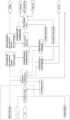
FIG. 1 is a flowchart of a PTA short-flow process for purifying condensed water according to the present disclosure; and -
FIG. 2 is a block diagram of the PTA short-flow process for purifying the condensed water according to the present disclosure. - The present disclosure is further explained and described below with reference to the accompanying drawings.
- Referring to
FIG. 1 , a dotted box shows an oxidation reactor (01) for producing PTA. PT and air are introduced into the oxidation reactor (01) in which there are acetic acid and the like, a reaction is performed to obtain a reaction liquid, and the reaction liquid is subjected to procedures of washing and the like to obtain a reactant and a refined mother liquor. The refined mother liquor contains a large amount of organic components such as the acetic acid, PT acid and the like, so that in a treatment system provided by the present disclosure, the refined mother liquor is used as a spraying liquid of a third-stage refined mother liquor washing unit. In addition, since the reaction is an exothermic reaction, a large amount of heat energy will be released during the reaction, and a part (reaction tail gas) of the reaction liquid will be evaporated upwards to go out from a pipeline. One of the objectives of the present disclosure is to enrich the reaction tail gas, then change it to be in a liquid form and return it to the oxidation reactor (01). - Provided is a treatment system for improving the water quality of a dehydration tower in a purified terephthalic acid device, the system including a dehydration washing device 1, a tail
gas condensation device 2 communicating with the top of the dehydration washing device 1 and awater separation device 3 communicating with the tailgas condensation device 2. - The dehydration washing device 1 includes a first-stage purified water washing unit 11 located at the top of the dehydration washing device, a second-stage concentrated
water washing unit 12 located in the middle of the dehydration washing device and a third-stage refined motherliquor washing unit 13 located at a lower portion of the dehydration washing device, and each of the units is washed by spraying. - After coming out from the bottom of the oxidation reactor (01), the reaction tail gas is introduced into the dehydration washing device 1, and an introduction inlet is formed in a lower portion of the third-stage refined mother
liquor washing unit 13. During the rising, the reaction tail gas firstly passes through the third-stage refined motherliquor washing unit 13 to be subjected to spray washing with the refined mother liquor, then passes through the second-stage concentratedwater washing unit 12 to be subjected to spray washing with concentrated water, and finally passes through the first-stage purified water washing unit 11 to be subjected to spray washing with purified water. After three times of spray washing, most of the organic components such as the acetic acid, the PT acid and the like in the reaction tail gas are enriched at the bottom of the dehydration washing device 1, this part of enriched liquid is returned to the oxidation reactor (01) again under the action of a circulatingpump 14 to continue to react, and the reaction tail gas containing a small part of the organic components such as the acetic acid, the PT acid and the like after washing is discharged from the top of the dehydration washing device 1 and enters a next process for other treatments. - Preferably, the dehydration washing device is a dehydration washing tower, the bottom of the dehydration washing tower communicates with the PTA oxidation reactor, and a concentrated reaction liquid (in which a large amount of the organic components such as the acetic acid, the PT acid and the like are enriched) after washing is returned to the oxidation reactor to continue to react, wherein the circulating pump may be used 14.
- The tail
gas condensation device 2 includes a first oxidized tailgas condensation system 21 including one or more stages of oxidized tail gas condensers that communicate in sequence and a second oxidized tailgas condensation system 22 located after the first oxidized tailgas condensation system 21 and including one or more stages of oxidized tail gas condensers that communicate in sequence, each stage of the oxidized tail gas condenser in the first oxidized tailgas condensation system 21 communicates to a first high-temperature condensed liquid tank 4 for containing a first condensed liquid obtained after heat exchange by the oxidized tail gas condensers in the system, and each stage of the oxidized tail gas condenser in the second oxidized tailgas condensation system 22 communicates to a second condensed liquid tank 5 for containing a second condensed liquid obtained after heat exchange by the oxidized tail gas condensers in the system and a second vapor channel for exporting vapor, wherein the oxidized tail gas condenser disposed at a tail end is provided with a tail gas discharge outlet. - The first oxidized tail
gas condensation system 21 includes 1-N, preferably 3 stages of oxidized tail gas condensers.FIG. 1 shows two stages of oxidized tail gas condensers. Each stage of oxidized tail gas condenser is provided with acold water inlet 211 and ahot water outlet 212. - In
FIG. 1 , after coming out from the top of the tailgas condensation device 2, reaction tail gas washed with the dehydration tower firstly enters a first-stage oxidized tail gas condenser and then enters other oxidized tail gas condensers backwards in sequence. In the process of flowing through these oxidized tail gas condensers, the reaction tail gas will exchange heat with cold water flowing in from thecold water inlet 211. After heat exchange, the cold water is heated, and the reaction tail gas in the oxidized tail gas condensers will be cooled, so that a part of the reaction tail gas will become a condensed liquid, namely, a first condensed liquid. The first condensed liquid produced by each stage of oxidized tail gas condenser will flow into the first high-temperature condensed liquid tank 4 through a pipeline. After being condensed through the first oxidized tailgas condensation system 21, the reaction tail gas enters the second oxidized tailgas condensation system 22 to continue to be condensed, and through the condensation treatment of the first oxidized tailgas condensation system 21, the temperature of the reaction tail gas and the pressure are reduced. - The second oxidized tail
gas condensation system 22 includes 1-4, preferably 3 stages of oxidized tail gas condensers.FIG. 1 shows three stages of oxidized tail gas condensers. The cold water is not used to exchange heat for each oxidized tail gas condenser in the second oxidized tailgas condensation system 22. During the natural flow, a part of the reaction tail gas is naturally condensed into the second condensed liquid and then enters the second condensed liquid tank 5 through a pipeline, and the reaction tail gas (second vapor) that is not condensed is discharged upwards. - The
water separation device 3 includes multi-effect evaporation units (31, 32, 33...) for purifying and separating the second condensed liquid, as well as a purifiedwater outlet 35 and a concentrated water outlet 34 after separation and purification, the purifiedwater outlet 35 communicates to the first-stage purified water washing unit 11 through a purified water pipeline, the second condensed liquid tank 5 communicates to the bottom of a first-effect evaporation unit through a second condensed liquid pipeline to separate the condensed liquid, and the second vapor channel extends into the first-effect evaporation unit through asecond vapor pipeline 221 to provide a heat source for heat exchange during the separation of the condensed liquid; the concentrated water outlet 34 communicates to the second-stage concentratedwater washing unit 12 through a concentrated water pipeline; and a purifiedwater heat exchanger 352 is disposed on the purified water pipeline, the first high-temperature condensed liquid tank 4 conducts heat exchange by the purifiedwater heat exchanger 352 through a high-temperature condensed liquid pipeline, a concentratedwater heat exchanger 351 is disposed on the concentrated water pipeline, and the first high-temperature condensed liquid tank 4 conducts heat exchange by the concentratedwater heat exchanger 351 through a high-temperature condensed liquid pipeline. - Preferably, the water separation device is a closed water separation tower, the evaporation units (31, 32, 33...) for purifying condensed water are disposed in a tower body, a final-effect condensation unit is disposed below the evaporation units, and a vacuum pump is connected to the bottom of the final-effect condensation unit. As shown in
FIG. 1 , the evaporation units include a first-effect evaporation unit 31 and a second-effect evaporation unit 32, the first-effect evaporation unit 31 includes a second condensedliquid inlet 311 and a firstheat exchange chamber 312, the second condensedliquid inlet 311 is located at the bottom of the first-effect evaporation unit 31, thesecond vapor pipeline 221 introduces the second vapor to the firstheat exchange chamber 312 to provide the heat source for heat exchange, the second condensed liquid exchanges heat with the second vapor in the firstheat exchange chamber 312, and a part of the second condensed liquid is gasified to separate water from other organic matter; an upper portion of the firstheat exchange chamber 312 is connected with afirst vapor passage 313 for a vapor phase to enter a next effect evaporation unit and afirst downcomer 314 for a liquid phase to flow to a next effect evaporation unit, and the bottom of thefirst downcomer 314 is provided with a first concentric-square-shaped device 315; the second-effect evaporation unit 32 includes a secondheat exchange chamber 321, an upper portion of the secondheat exchange chamber 321 is provided with asecond vapor passage 323 for a vapor phase to pass through after heat exchange of the condensed water and asecond downcomer 324 for a liquid phase to pass through, and the bottom of thesecond downcomer 324 is provided with a second concentric-square-shaped device 325; a lower portion of the secondheat exchange chamber 32 is provided with a first condensedliquid channel 326 for the condensed liquid to flow to the next effect evaporation unit after heat exchange, and the bottom of the first condensedliquid channel 326 is provided with afirst U-shaped tube 327; and the first concentric-square-shaped device 325 is located between the second heat exchange chamber and a second demister. Vapor of 0.05 MPa (G) is recommended as the vapor entering the water separation tower, which may also be vapor of 0.05-0.5 MPa (G) produced by any stage of oxidized tail gas condenser or vapor introduced from outside. - In the water separation tower, the second condensed liquid is continuously separated and purified. The
vacuum pump 36 located at the bottom is turned on, the second condensed liquid enters the firstheat exchange chamber 312 from the second condensedliquid inlet 311 to be evaporated, and the second vapor enters a pipeline in the firstheat exchange chamber 312 from thesecond vapor pipeline 221. The second vapor and the second condensed liquid exchange heat in the firstheat exchange chamber 312. Apart of the second condensed liquid is volatilized and enters thefirst vapor passage 313 upwards, and a part of the condensed liquid that is not evaporated enters thefirst downcomer 314 and then enter the next effect evaporation unit to continue to be evaporated or stay at the first concentric-square-shaped device 315. The vapor entering a pipeline in the second-effect evaporation unit 32 through thefirst vapor passage 313 continues to be used as a heat source to exchange heat with a condensed liquid flowing out of thefirst downcomer 314, heat of the vapor flows to the condensed liquid, finally the vapor is cooled and flows out of the first condensedliquid channel 326, and a part of the condensed liquid is gathered in the firstU-shaped tube 327 and finally flows to a purified water storage area at the bottom. The first concentric-square-shapeddevice 315 and the firstU-shaped tube 327 isolate the effect evaporation units, and in this way, under the action of the vacuum pump 26, the pressure gradually decreases from top to bottom, so that the first concentric-square-shapeddevice 315 will also perform spontaneous evaporation under the action of a pressure difference and heat exchange to separate water from other substances. After separation, the purified water is discharged from the purifiedwater outlet 35 through a pipeline, exchanges heat with a first high-temperature condensed liquid through the purifiedwater heat exchanger 352 to be heated, and then sprays the reaction tail gas as a washing liquid of the first-stage purified water washing unit; and the concentrated water is discharged from the concentrated water outlet 34 through a pipeline, and performs spray washing on the reaction tail gas as a washing liquid of the second-stage concentrated water washing unit through the concentratedwater heat exchanger 351. The concentrated water produced by the novel water separation tower may enter the dehydration tower, and may also be used as a washing liquid of a crude terephthalic acid (CTA for short, hereinafter referred to as CTA) solvent exchange unit. - In the whole system, as shown in the figures, various types of pumps or valves will be installed reasonably according to the actual needs to achieve the smoothness of the system.
Claims (5)
- A treatment system for improving the water quality of a dehydration tower in a purified terephthalic acid device, the system comprising a dehydration washing device (1), a tail gas condensation device (2) communicating with the top of the dehydration washing device (1), and a water separation device (3) communicating with the tail gas condensation device (2), whereinthe dehydration washing device (1) comprises a first-stage purified water washing unit (11) located at the top of the dehydration washing device (1), a second-stage concentrated water washing unit (12) located in the middle of the dehydration washing device (1), and a third-stage refined mother liquor washing unit (13) located at a lower portion of the dehydration washing device (1);the tail gas condensation device (2) is connected with a first high-temperature condensed liquid tank (4) for containing a first condensed liquid obtained after first heat exchange by oxidized tail gas condensers in the system, a second condensed liquid tank (5) for containing a second condensed liquid obtained after second heat exchange by the oxidized tail gas condensers in the system, and a second vapor channel for exporting vapor; andthe water separation device (3) comprises multi-effect evaporation units (31, 32, 33) for purifying and separating the second condensed liquid, as well as a purified water outlet (35) and a concentrated water outlet (34) after separation and purification, the purified water outlet (35) communicates to the first-stage purified water washing unit (11) through a purified water pipeline, the second condensed liquid tank (5) communicates to the bottom of a first-effect evaporation unit through a second condensed liquid pipeline to separate the condensed liquid, and the second vapor channel extends into the first-effect evaporation unit through a second vapor pipeline (221) to provide a heat source for heat exchange during the separation of the condensed liquid; and the concentrated water outlet (34) communicates to the second-stage concentrated water washing unit (12) through a concentrated water pipeline; and a purified water heat exchanger (352) is disposed on the purified water pipeline, the first high-temperature condensed liquid tank (4) conducts heat exchange by the purified water heat exchanger (352) through a high-temperature condensed liquid pipeline, a concentrated water heat exchanger (351) is disposed on the concentrated water pipeline, and the first high-temperature condensed liquid tank (4) conducts heat exchange by the concentrated water heat exchanger (351) through a second high-temperature condensed liquid pipeline, wherein the tail gas condensation device comprises a first oxidized tail gas condensation system (21) comprising one or more stages of oxidized tail gas condensers that communicate in sequence and a second oxidized tail gas condensation system (22) located after the first oxidized tail gas condensation system and comprising one or more stages of oxidized tail gas condensers that communicate in sequence, each stage of the oxidized tail gas condenser in the first oxidized tail gas condensation system (21) communicates to the first high-temperature condensed liquid tank (4), and each stage of the oxidized tail gas condenser in the second oxidized tail gas condensation system communicates to the second condensed liquid tank (5) and the second vapor channel for exporting the vapor wherein the dehydration washing device is a dehydration washing tower, the bottom of the dehydration washing tower communicates with a purified terephthalic acid (PTA) oxidation reactor (01), and a concentrated reaction liquid after washing is returned to the oxidation reactor to continue to react, wherein the water separation device is a water separation tower, the evaporation units for purifying condensed water are disposed in a tower body, a final-effect condensation unit is disposed below the evaporation units, and a vacuum pump (36) is connected to the bottom of the final-effect condensation unit, wherein the first-stage purified water washing unit (11), the second-stage concentrated water washing unit (12) and the third-stage refined mother liquor washing unit (13) are respectively provided with spray heads to wash tail gas by spraying.
- The treatment system for improving the water quality of a dehydration tower in a purified terephthalic acid device according to claim 1, wherein the first oxidized tail gas condensation system (21) comprises 1-4 stages of oxidized tail gas condensers, and/or the second oxidized tail gas condensation system (22) comprises 1-4 stages of oxidized tail gas condensers.
- The treatment system for improving the water quality of a dehydration tower in a purified terephthalic acid device according to claim 1, wherein the evaporation units comprise a first-effect evaporation unit (31) and a second-effect evaporation unit (32), the first-effect evaporation unit (31) comprises a second condensed liquid inlet (311) and a first heat exchange chamber (312), an upper portion of the first heat exchange chamber is connected with a first vapor passage (313) for a vapor phase to enter a next effect evaporation unit and a first downcomer (314) for a liquid phase to flow to a next effect evaporation unit, and the bottom of the first downcomer is provided with a first concentric-square-shaped device (315); the second-effect evaporation unit (32) comprises a second heat exchange chamber (321), an upper portion of the second heat exchange chamber is provided with a second vapor passage (323) for a vapor phase to pass through after heat exchange of the condensed water and a second downcomer (324) for a liquid phase to pass through, and the bottom of the second downcomer is provided with a second concentric-square-shaped device (325); a lower portion of the second heat exchange chamber (32) is provided with a first condensed liquid channel (326) for the condensed liquid to flow to the next effect evaporation unit after heat exchange, and the bottom of the first condensed liquid channel (326) is provided with a first U-shaped tube (327); and the first concentric-square-shaped device (325) is located between the second heat exchange chamber and a second demister.
- A method for improving the water quality of a dehydration tower in a purified terephthalic acid device according to claim 1, the method comprising the following steps:1) introducing, after reaction tail gas comes out from the bottom of the oxidation reactor (01), the reaction tail gas into a lower portion of the third-stage refined mother liquor washing unit (13), and during the rising, enabling the reaction tail gas to firstly pass through the third-stage refined mother liquor washing unit (13) to be subjected to spray washing with a refined mother liquor, then pass through the second-stage concentrated water washing unit (12) to be subjected to spray washing with concentrated water and finally pass through the first-stage purified water washing unit (11) to be subjected to spray washing with purified water;2) enabling, after the reaction tail gas washed with the dehydration tower comes out from the top of a tail gas condensation device (2), the reaction tail gas to firstly enter a first-stage oxidized tail gas condenser and then enter other oxidized tail gas condensers backwards in sequence to exchange heat for cooling, wherein a part of the tail gas will become a condensed liquid, namely, a first condensed liquid, and the first condensed liquid produced by each stage of oxidized tail gas condenser will flow into a first high-temperature condensed liquid tank (4) through a pipeline; and after the reaction tail gas is condensed through a first oxidized tail gas condensation system (21), enabling the reaction tail gas to enter a second oxidized tail gas condensation system (22) to continue to be condensed, so as to form a second condensed liquid through the condensation treatment of the first oxidized tail gas condensation system (21), then enabling the second condensed liquid to enter a second condensed liquid tank (5) through a pipeline, and discharging second vapor that is not condensed upwards;3) enabling the second condensed liquid to enter the water separation tower to be continuously separated and purified; and4) after separation, discharging the purified water from the purified water outlet (35) through a pipeline, exchanging heat with a first high-temperature condensed liquid through the purified water heat exchanger (352) to increase the temperature of the purified water, and then spraying the reaction tail gas with the purified water as a washing liquid of the first-stage purified water washing unit (11); and discharging the concentrated water from the concentrated water outlet (34) through a pipeline, and performing spray washing on the reaction tail gas with the concentrated water as a washing liquid of the second-stage concentrated water washing unit (12) through the concentrated water heat exchanger (351).
- The method according to claim 4, wherein step 3 comprises: turning on the vacuum pump (36) located at the bottom, enabling the second condensed liquid to enter a first heat exchange chamber (312) from a second condensed liquid inlet to be evaporated, enabling the second vapor to enter a pipeline in the first heat exchange chamber from a second vapor pipeline (221), enabling the second vapor and the second condensed liquid to exchange heat in the first heat exchange chamber (312), enabling a part of the second condensed liquid to be volatilized and enter a first vapor passage (313) upwards, enabling the vapor entering a pipeline in a second-effect evaporation unit through the first vapor passage to continue to be used as a heat source to exchange heat with a condensed liquid flowing out of a first downcomer (314), enabling heat of the vapor to flow to the condensed liquid, finally enabling the vapor to be cooled and flow out of a first condensed liquid channel, and enabling a part of the condensed liquid to be gathered in a first U-shaped tube (327) and finally flow to a purified water storage area at the bottom; and enabling a part of the condensed liquid that is not evaporated to enter the first downcomer (314) and then enter a next effect evaporation unit to continue to be evaporated or stay at a first concentric-square-shaped device (315).
Applications Claiming Priority (2)
| Application Number | Priority Date | Filing Date | Title |
|---|---|---|---|
| CN202111483557.1A CN114057252B (en) | 2021-12-07 | 2021-12-07 | System and method for improving water quality of dehydration tower of purified terephthalic acid device |
| PCT/CN2022/092909 WO2023103283A1 (en) | 2021-12-07 | 2022-05-16 | System and method for improving water quality of dehydrating tower of purified terephthalic acid apparatus |
Publications (3)
| Publication Number | Publication Date |
|---|---|
| EP4219407A1 EP4219407A1 (en) | 2023-08-02 |
| EP4219407A4 EP4219407A4 (en) | 2023-08-23 |
| EP4219407B1 true EP4219407B1 (en) | 2024-07-17 |
Family
ID=80228755
Family Applications (1)
| Application Number | Title | Priority Date | Filing Date |
|---|---|---|---|
| EP22736133.4A Active EP4219407B1 (en) | 2021-12-07 | 2022-05-16 | System and method for improving water quality of dehydrating tower of purified terephthalic acid apparatus |
Country Status (7)
| Country | Link |
|---|---|
| US (1) | US20240050873A1 (en) |
| EP (1) | EP4219407B1 (en) |
| JP (1) | JP7607664B2 (en) |
| CN (1) | CN114057252B (en) |
| SA (1) | SA523441340B1 (en) |
| TW (1) | TWI815463B (en) |
| WO (1) | WO2023103283A1 (en) |
Families Citing this family (2)
| Publication number | Priority date | Publication date | Assignee | Title |
|---|---|---|---|---|
| CN114057252B (en) * | 2021-12-07 | 2024-05-03 | 天华化工机械及自动化研究设计院有限公司 | System and method for improving water quality of dehydration tower of purified terephthalic acid device |
| CN119056189B (en) * | 2024-09-26 | 2025-04-25 | 江西世龙实业股份有限公司 | Tail gas treatment system and method for producing 80% hydrazine hydrate by rectification and purification |
Family Cites Families (15)
| Publication number | Priority date | Publication date | Assignee | Title |
|---|---|---|---|---|
| FR754118A (en) * | 1932-04-23 | 1933-10-31 | ||
| JP3864561B2 (en) * | 1998-06-05 | 2007-01-10 | 三井化学株式会社 | Method for producing aromatic carboxylic acid |
| FI20030735L (en) * | 2003-05-16 | 2004-11-17 | Steris Europe Inc | Method and device for treating water |
| DE602006015446D1 (en) * | 2005-03-21 | 2010-08-26 | Bp Corp North America Inc | METHOD AND DEVICE FOR PREPARING AROMATIC CARBOXYLIC ACIDS INCLUDING PURE FORMS THEREOF |
| KR100744754B1 (en) * | 2005-12-13 | 2007-08-01 | 삼성석유화학(주) | Method for producing aromatic carboxylic acid |
| KR100794317B1 (en) * | 2006-02-20 | 2008-01-11 | (주)에이엠티퍼시픽 | Method for removing water from reactor exhaust gas during the oxidation of aromatic compounds |
| CN1951900A (en) * | 2006-11-10 | 2007-04-25 | 浙江大学 | Low-energy consumption preparation method of terephthalic acid |
| CN101537299B (en) * | 2009-03-19 | 2011-12-28 | 绍兴远东石化有限公司 | Method for recycling organic matters in tail gas from production of terephthalic acid |
| RU2687489C1 (en) * | 2013-12-18 | 2019-05-14 | Бипи Корпорейшен Норт Америка Инк. | Improved method and device for production of aromatic carboxylic acids |
| CN105001073B (en) * | 2015-07-02 | 2017-06-20 | 中国石油天然气集团公司 | Low energy consumption material consumption, the PTA production methods and system of few waste discharge |
| CN106115825A (en) * | 2016-08-19 | 2016-11-16 | 北京今大禹环境技术股份有限公司 | A kind of low temperature multiple-effect distillation seawater desalination system |
| CN110078284B (en) * | 2019-04-25 | 2021-08-24 | 杭州多向流化学科技有限公司 | Water-rich solvent grading utilization emission reduction system for preparing terephthalic acid |
| CN112807722A (en) * | 2021-01-04 | 2021-05-18 | 中石化上海工程有限公司 | Continuous cascade thin film evaporator system |
| CN216808188U (en) * | 2021-12-07 | 2022-06-24 | 天华化工机械及自动化研究设计院有限公司 | System for improving water quality of dewatering tower of purified terephthalic acid device |
| CN114057252B (en) * | 2021-12-07 | 2024-05-03 | 天华化工机械及自动化研究设计院有限公司 | System and method for improving water quality of dehydration tower of purified terephthalic acid device |
-
2021
- 2021-12-07 CN CN202111483557.1A patent/CN114057252B/en active Active
-
2022
- 2022-05-16 EP EP22736133.4A patent/EP4219407B1/en active Active
- 2022-05-16 JP JP2022544421A patent/JP7607664B2/en active Active
- 2022-05-16 US US18/260,294 patent/US20240050873A1/en active Pending
- 2022-05-16 WO PCT/CN2022/092909 patent/WO2023103283A1/en not_active Ceased
- 2022-05-20 TW TW111118920A patent/TWI815463B/en active
-
2023
- 2023-06-20 SA SA523441340A patent/SA523441340B1/en unknown
Also Published As
| Publication number | Publication date |
|---|---|
| JP7607664B2 (en) | 2024-12-27 |
| TW202322881A (en) | 2023-06-16 |
| JP2024502219A (en) | 2024-01-18 |
| CN114057252A (en) | 2022-02-18 |
| TWI815463B (en) | 2023-09-11 |
| SA523441340B1 (en) | 2025-04-29 |
| EP4219407A1 (en) | 2023-08-02 |
| WO2023103283A1 (en) | 2023-06-15 |
| CN114057252B (en) | 2024-05-03 |
| EP4219407A4 (en) | 2023-08-23 |
| US20240050873A1 (en) | 2024-02-15 |
Similar Documents
| Publication | Publication Date | Title |
|---|---|---|
| CN111437619B (en) | Multi-tower differential pressure energy-saving absolute alcohol distillation system and absolute alcohol energy-saving production method | |
| CN109134233B (en) | A kind of process units and production method of synthesizing acetic acid by methanol low-voltage carbonylation | |
| CN112608232B (en) | System and method for recycling reaction heat in process of synthesizing acetic acid by methanol low-pressure carbonyl | |
| EP4219407A1 (en) | System and method for improving water quality of dehydrating tower of purified terephthalic acid apparatus | |
| RU2396242C2 (en) | Method of methanol recuperation | |
| CN110404285B (en) | Four-tower distillation and membrane separation integrated system and method for distilling ethanol | |
| CN114797145A (en) | Differential pressure thermal coupling rectification process for coal-to-ethylene glycol byproduct | |
| CN216808188U (en) | System for improving water quality of dewatering tower of purified terephthalic acid device | |
| CN110078284A (en) | It is used to prepare the rich water solvent classified utilization emission-reducing system of terephthalic acid (TPA) | |
| TW201925151A (en) | Processes for the production of ethylene oxide and ethylene glycol | |
| CN114044551B (en) | Separation tower for treating condensed water and method thereof | |
| CN216808187U (en) | Separation tower for treating condensed water | |
| CN212818177U (en) | Multi-tower differential pressure energy-saving anhydrous alcohol distillation system | |
| CN116850621B (en) | A system for producing paraformaldehyde using heat pump-assisted reactive distillation coupled with pressure swing distillation and its energy-saving process. | |
| EA050425B1 (en) | SYSTEM AND METHOD FOR IMPROVING WATER QUALITY IN THE DEWATERING COLUMN OF A PURE TEREPHTHALIC ACID (PTA) PRODUCTION PLANT | |
| CN115350566A (en) | Improved low-temperature methanol-washing CO 2 Device and process for desorbing and utilizing desorbed gas | |
| CN217312008U (en) | Acrylic acid purification device capable of recycling energy | |
| CN224166921U (en) | Device for refining acetophenone and alpha-phenethyl alcohol | |
| CN205774226U (en) | A kind of energy saver of caprolactam system | |
| CN116272736B (en) | Continuous production method of diethyl maleate | |
| CN218166519U (en) | Purification and quality improvement system for residual ammonia water and ammonia distillation strong ammonia water | |
| CN119406075B (en) | Product separation device and method for preparing ethanol by hydrogenation of energy-saving acetate | |
| CN222033656U (en) | A silane gas production system | |
| CN219743939U (en) | Energy-saving tetrahydrofuran aqueous solution rectifying system | |
| CN116120167B (en) | A method for efficiently purifying methacrylic acid |
Legal Events
| Date | Code | Title | Description |
|---|---|---|---|
| STAA | Information on the status of an ep patent application or granted ep patent |
Free format text: STATUS: UNKNOWN |
|
| STAA | Information on the status of an ep patent application or granted ep patent |
Free format text: STATUS: THE INTERNATIONAL PUBLICATION HAS BEEN MADE |
|
| PUAI | Public reference made under article 153(3) epc to a published international application that has entered the european phase |
Free format text: ORIGINAL CODE: 0009012 |
|
| STAA | Information on the status of an ep patent application or granted ep patent |
Free format text: STATUS: REQUEST FOR EXAMINATION WAS MADE |
|
| 17P | Request for examination filed |
Effective date: 20220715 |
|
| AK | Designated contracting states |
Kind code of ref document: A1 Designated state(s): AL AT BE BG CH CY CZ DE DK EE ES FI FR GB GR HR HU IE IS IT LI LT LU LV MC MK MT NL NO PL PT RO RS SE SI SK SM TR |
|
| A4 | Supplementary search report drawn up and despatched |
Effective date: 20230725 |
|
| RIC1 | Information provided on ipc code assigned before grant |
Ipc: C08G 63/183 20060101ALI20230719BHEP Ipc: B01D 53/26 20060101ALI20230719BHEP Ipc: B01D 53/00 20060101ALI20230719BHEP Ipc: C02F 103/36 20060101ALI20230719BHEP Ipc: F28B 7/00 20060101ALI20230719BHEP Ipc: C07C 63/26 20060101ALI20230719BHEP Ipc: B01D 53/14 20060101ALI20230719BHEP Ipc: C02F 1/16 20230101AFI20230719BHEP |
|
| GRAP | Despatch of communication of intention to grant a patent |
Free format text: ORIGINAL CODE: EPIDOSNIGR1 |
|
| STAA | Information on the status of an ep patent application or granted ep patent |
Free format text: STATUS: GRANT OF PATENT IS INTENDED |
|
| INTG | Intention to grant announced |
Effective date: 20240207 |
|
| GRAS | Grant fee paid |
Free format text: ORIGINAL CODE: EPIDOSNIGR3 |
|
| GRAA | (expected) grant |
Free format text: ORIGINAL CODE: 0009210 |
|
| STAA | Information on the status of an ep patent application or granted ep patent |
Free format text: STATUS: THE PATENT HAS BEEN GRANTED |
|
| DAV | Request for validation of the european patent (deleted) | ||
| DAX | Request for extension of the european patent (deleted) | ||
| AK | Designated contracting states |
Kind code of ref document: B1 Designated state(s): AL AT BE BG CH CY CZ DE DK EE ES FI FR GB GR HR HU IE IS IT LI LT LU LV MC MK MT NL NO PL PT RO RS SE SI SK SM TR |
|
| REG | Reference to a national code |
Ref country code: CH Ref legal event code: EP |
|
| REG | Reference to a national code |
Ref country code: DE Ref legal event code: R096 Ref document number: 602022004661 Country of ref document: DE |
|
| REG | Reference to a national code |
Ref country code: IE Ref legal event code: FG4D |
|
| REG | Reference to a national code |
Ref country code: LT Ref legal event code: MG9D |
|
| REG | Reference to a national code |
Ref country code: NL Ref legal event code: MP Effective date: 20240717 |
|
| PG25 | Lapsed in a contracting state [announced via postgrant information from national office to epo] |
Ref country code: PT Free format text: LAPSE BECAUSE OF FAILURE TO SUBMIT A TRANSLATION OF THE DESCRIPTION OR TO PAY THE FEE WITHIN THE PRESCRIBED TIME-LIMIT Effective date: 20241118 |
|
| REG | Reference to a national code |
Ref country code: AT Ref legal event code: MK05 Ref document number: 1703989 Country of ref document: AT Kind code of ref document: T Effective date: 20240717 |
|
| PG25 | Lapsed in a contracting state [announced via postgrant information from national office to epo] |
Ref country code: NL Free format text: LAPSE BECAUSE OF FAILURE TO SUBMIT A TRANSLATION OF THE DESCRIPTION OR TO PAY THE FEE WITHIN THE PRESCRIBED TIME-LIMIT Effective date: 20240717 |
|
| PG25 | Lapsed in a contracting state [announced via postgrant information from national office to epo] |
Ref country code: PT Free format text: LAPSE BECAUSE OF FAILURE TO SUBMIT A TRANSLATION OF THE DESCRIPTION OR TO PAY THE FEE WITHIN THE PRESCRIBED TIME-LIMIT Effective date: 20241118 Ref country code: NL Free format text: LAPSE BECAUSE OF FAILURE TO SUBMIT A TRANSLATION OF THE DESCRIPTION OR TO PAY THE FEE WITHIN THE PRESCRIBED TIME-LIMIT Effective date: 20240717 |
|
| PG25 | Lapsed in a contracting state [announced via postgrant information from national office to epo] |
Ref country code: NO Free format text: LAPSE BECAUSE OF FAILURE TO SUBMIT A TRANSLATION OF THE DESCRIPTION OR TO PAY THE FEE WITHIN THE PRESCRIBED TIME-LIMIT Effective date: 20241017 |
|
| PG25 | Lapsed in a contracting state [announced via postgrant information from national office to epo] |
Ref country code: FI Free format text: LAPSE BECAUSE OF FAILURE TO SUBMIT A TRANSLATION OF THE DESCRIPTION OR TO PAY THE FEE WITHIN THE PRESCRIBED TIME-LIMIT Effective date: 20240717 Ref country code: PL Free format text: LAPSE BECAUSE OF FAILURE TO SUBMIT A TRANSLATION OF THE DESCRIPTION OR TO PAY THE FEE WITHIN THE PRESCRIBED TIME-LIMIT Effective date: 20240717 Ref country code: GR Free format text: LAPSE BECAUSE OF FAILURE TO SUBMIT A TRANSLATION OF THE DESCRIPTION OR TO PAY THE FEE WITHIN THE PRESCRIBED TIME-LIMIT Effective date: 20241018 |
|
| PG25 | Lapsed in a contracting state [announced via postgrant information from national office to epo] |
Ref country code: BG Free format text: LAPSE BECAUSE OF FAILURE TO SUBMIT A TRANSLATION OF THE DESCRIPTION OR TO PAY THE FEE WITHIN THE PRESCRIBED TIME-LIMIT Effective date: 20240717 |
|
| PG25 | Lapsed in a contracting state [announced via postgrant information from national office to epo] |
Ref country code: LV Free format text: LAPSE BECAUSE OF FAILURE TO SUBMIT A TRANSLATION OF THE DESCRIPTION OR TO PAY THE FEE WITHIN THE PRESCRIBED TIME-LIMIT Effective date: 20240717 |
|
| PG25 | Lapsed in a contracting state [announced via postgrant information from national office to epo] |
Ref country code: AT Free format text: LAPSE BECAUSE OF FAILURE TO SUBMIT A TRANSLATION OF THE DESCRIPTION OR TO PAY THE FEE WITHIN THE PRESCRIBED TIME-LIMIT Effective date: 20240717 Ref country code: IS Free format text: LAPSE BECAUSE OF FAILURE TO SUBMIT A TRANSLATION OF THE DESCRIPTION OR TO PAY THE FEE WITHIN THE PRESCRIBED TIME-LIMIT Effective date: 20241117 |
|
| PG25 | Lapsed in a contracting state [announced via postgrant information from national office to epo] |
Ref country code: HR Free format text: LAPSE BECAUSE OF FAILURE TO SUBMIT A TRANSLATION OF THE DESCRIPTION OR TO PAY THE FEE WITHIN THE PRESCRIBED TIME-LIMIT Effective date: 20240717 |
|
| PG25 | Lapsed in a contracting state [announced via postgrant information from national office to epo] |
Ref country code: ES Free format text: LAPSE BECAUSE OF FAILURE TO SUBMIT A TRANSLATION OF THE DESCRIPTION OR TO PAY THE FEE WITHIN THE PRESCRIBED TIME-LIMIT Effective date: 20240717 Ref country code: RS Free format text: LAPSE BECAUSE OF FAILURE TO SUBMIT A TRANSLATION OF THE DESCRIPTION OR TO PAY THE FEE WITHIN THE PRESCRIBED TIME-LIMIT Effective date: 20241017 |
|
| PG25 | Lapsed in a contracting state [announced via postgrant information from national office to epo] |
Ref country code: RS Free format text: LAPSE BECAUSE OF FAILURE TO SUBMIT A TRANSLATION OF THE DESCRIPTION OR TO PAY THE FEE WITHIN THE PRESCRIBED TIME-LIMIT Effective date: 20241017 Ref country code: PL Free format text: LAPSE BECAUSE OF FAILURE TO SUBMIT A TRANSLATION OF THE DESCRIPTION OR TO PAY THE FEE WITHIN THE PRESCRIBED TIME-LIMIT Effective date: 20240717 Ref country code: NO Free format text: LAPSE BECAUSE OF FAILURE TO SUBMIT A TRANSLATION OF THE DESCRIPTION OR TO PAY THE FEE WITHIN THE PRESCRIBED TIME-LIMIT Effective date: 20241017 Ref country code: LV Free format text: LAPSE BECAUSE OF FAILURE TO SUBMIT A TRANSLATION OF THE DESCRIPTION OR TO PAY THE FEE WITHIN THE PRESCRIBED TIME-LIMIT Effective date: 20240717 Ref country code: IS Free format text: LAPSE BECAUSE OF FAILURE TO SUBMIT A TRANSLATION OF THE DESCRIPTION OR TO PAY THE FEE WITHIN THE PRESCRIBED TIME-LIMIT Effective date: 20241117 Ref country code: HR Free format text: LAPSE BECAUSE OF FAILURE TO SUBMIT A TRANSLATION OF THE DESCRIPTION OR TO PAY THE FEE WITHIN THE PRESCRIBED TIME-LIMIT Effective date: 20240717 Ref country code: GR Free format text: LAPSE BECAUSE OF FAILURE TO SUBMIT A TRANSLATION OF THE DESCRIPTION OR TO PAY THE FEE WITHIN THE PRESCRIBED TIME-LIMIT Effective date: 20241018 Ref country code: FI Free format text: LAPSE BECAUSE OF FAILURE TO SUBMIT A TRANSLATION OF THE DESCRIPTION OR TO PAY THE FEE WITHIN THE PRESCRIBED TIME-LIMIT Effective date: 20240717 Ref country code: ES Free format text: LAPSE BECAUSE OF FAILURE TO SUBMIT A TRANSLATION OF THE DESCRIPTION OR TO PAY THE FEE WITHIN THE PRESCRIBED TIME-LIMIT Effective date: 20240717 Ref country code: BG Free format text: LAPSE BECAUSE OF FAILURE TO SUBMIT A TRANSLATION OF THE DESCRIPTION OR TO PAY THE FEE WITHIN THE PRESCRIBED TIME-LIMIT Effective date: 20240717 Ref country code: AT Free format text: LAPSE BECAUSE OF FAILURE TO SUBMIT A TRANSLATION OF THE DESCRIPTION OR TO PAY THE FEE WITHIN THE PRESCRIBED TIME-LIMIT Effective date: 20240717 |
|
| PG25 | Lapsed in a contracting state [announced via postgrant information from national office to epo] |
Ref country code: RO Free format text: LAPSE BECAUSE OF FAILURE TO SUBMIT A TRANSLATION OF THE DESCRIPTION OR TO PAY THE FEE WITHIN THE PRESCRIBED TIME-LIMIT Effective date: 20240717 Ref country code: DK Free format text: LAPSE BECAUSE OF FAILURE TO SUBMIT A TRANSLATION OF THE DESCRIPTION OR TO PAY THE FEE WITHIN THE PRESCRIBED TIME-LIMIT Effective date: 20240717 Ref country code: SM Free format text: LAPSE BECAUSE OF FAILURE TO SUBMIT A TRANSLATION OF THE DESCRIPTION OR TO PAY THE FEE WITHIN THE PRESCRIBED TIME-LIMIT Effective date: 20240717 |
|
| REG | Reference to a national code |
Ref country code: DE Ref legal event code: R097 Ref document number: 602022004661 Country of ref document: DE |
|
| PG25 | Lapsed in a contracting state [announced via postgrant information from national office to epo] |
Ref country code: EE Free format text: LAPSE BECAUSE OF FAILURE TO SUBMIT A TRANSLATION OF THE DESCRIPTION OR TO PAY THE FEE WITHIN THE PRESCRIBED TIME-LIMIT Effective date: 20240717 |
|
| PG25 | Lapsed in a contracting state [announced via postgrant information from national office to epo] |
Ref country code: CZ Free format text: LAPSE BECAUSE OF FAILURE TO SUBMIT A TRANSLATION OF THE DESCRIPTION OR TO PAY THE FEE WITHIN THE PRESCRIBED TIME-LIMIT Effective date: 20240717 |
|
| PG25 | Lapsed in a contracting state [announced via postgrant information from national office to epo] |
Ref country code: SK Free format text: LAPSE BECAUSE OF FAILURE TO SUBMIT A TRANSLATION OF THE DESCRIPTION OR TO PAY THE FEE WITHIN THE PRESCRIBED TIME-LIMIT Effective date: 20240717 |
|
| PLBE | No opposition filed within time limit |
Free format text: ORIGINAL CODE: 0009261 |
|
| STAA | Information on the status of an ep patent application or granted ep patent |
Free format text: STATUS: NO OPPOSITION FILED WITHIN TIME LIMIT |
|
| 26N | No opposition filed |
Effective date: 20250422 |
|
| PGFP | Annual fee paid to national office [announced via postgrant information from national office to epo] |
Ref country code: BE Payment date: 20250527 Year of fee payment: 4 |
|
| PG25 | Lapsed in a contracting state [announced via postgrant information from national office to epo] |
Ref country code: SE Free format text: LAPSE BECAUSE OF FAILURE TO SUBMIT A TRANSLATION OF THE DESCRIPTION OR TO PAY THE FEE WITHIN THE PRESCRIBED TIME-LIMIT Effective date: 20240717 |
|
| REG | Reference to a national code |
Ref country code: DE Ref legal event code: R119 Ref document number: 602022004661 Country of ref document: DE |
|
| REG | Reference to a national code |
Ref country code: CH Ref legal event code: H13 Free format text: ST27 STATUS EVENT CODE: U-0-0-H10-H13 (AS PROVIDED BY THE NATIONAL OFFICE) Effective date: 20251223 |
|
| PG25 | Lapsed in a contracting state [announced via postgrant information from national office to epo] |
Ref country code: LU Free format text: LAPSE BECAUSE OF NON-PAYMENT OF DUE FEES Effective date: 20250516 |
|
| PG25 | Lapsed in a contracting state [announced via postgrant information from national office to epo] |
Ref country code: CH Free format text: LAPSE BECAUSE OF NON-PAYMENT OF DUE FEES Effective date: 20250531 |
|
| PG25 | Lapsed in a contracting state [announced via postgrant information from national office to epo] |
Ref country code: IT Free format text: LAPSE BECAUSE OF FAILURE TO SUBMIT A TRANSLATION OF THE DESCRIPTION OR TO PAY THE FEE WITHIN THE PRESCRIBED TIME-LIMIT Effective date: 20240717 |
|
| PG25 | Lapsed in a contracting state [announced via postgrant information from national office to epo] |
Ref country code: MC Free format text: LAPSE BECAUSE OF FAILURE TO SUBMIT A TRANSLATION OF THE DESCRIPTION OR TO PAY THE FEE WITHIN THE PRESCRIBED TIME-LIMIT Effective date: 20240717 |
|
| PG25 | Lapsed in a contracting state [announced via postgrant information from national office to epo] |
Ref country code: DE Free format text: LAPSE BECAUSE OF NON-PAYMENT OF DUE FEES Effective date: 20251202 Ref country code: IE Free format text: LAPSE BECAUSE OF NON-PAYMENT OF DUE FEES Effective date: 20250516 |
|
| PG25 | Lapsed in a contracting state [announced via postgrant information from national office to epo] |
Ref country code: FR Free format text: LAPSE BECAUSE OF NON-PAYMENT OF DUE FEES Effective date: 20250531 |