EP4219294A1 - Improvements relating to wing construction - Google Patents
Improvements relating to wing construction Download PDFInfo
- Publication number
- EP4219294A1 EP4219294A1 EP23153389.4A EP23153389A EP4219294A1 EP 4219294 A1 EP4219294 A1 EP 4219294A1 EP 23153389 A EP23153389 A EP 23153389A EP 4219294 A1 EP4219294 A1 EP 4219294A1
- Authority
- EP
- European Patent Office
- Prior art keywords
- brackets
- spar
- aircraft wing
- systems module
- wing structure
- Prior art date
- Legal status (The legal status is an assumption and is not a legal conclusion. Google has not performed a legal analysis and makes no representation as to the accuracy of the status listed.)
- Granted
Links
Images


Classifications
-
- B—PERFORMING OPERATIONS; TRANSPORTING
- B64—AIRCRAFT; AVIATION; COSMONAUTICS
- B64C—AEROPLANES; HELICOPTERS
- B64C3/00—Wings
- B64C3/18—Spars; Ribs; Stringers
- B64C3/185—Spars
-
- B—PERFORMING OPERATIONS; TRANSPORTING
- B64—AIRCRAFT; AVIATION; COSMONAUTICS
- B64C—AEROPLANES; HELICOPTERS
- B64C3/00—Wings
- B64C3/18—Spars; Ribs; Stringers
- B64C3/182—Stringers, longerons
-
- B—PERFORMING OPERATIONS; TRANSPORTING
- B64—AIRCRAFT; AVIATION; COSMONAUTICS
- B64C—AEROPLANES; HELICOPTERS
- B64C3/00—Wings
- B64C3/34—Tanks constructed integrally with wings, e.g. for fuel or water
-
- B—PERFORMING OPERATIONS; TRANSPORTING
- B64—AIRCRAFT; AVIATION; COSMONAUTICS
- B64D—EQUIPMENT FOR FITTING IN OR TO AIRCRAFT; FLIGHT SUITS; PARACHUTES; ARRANGEMENT OR MOUNTING OF POWER PLANTS OR PROPULSION TRANSMISSIONS IN AIRCRAFT
- B64D37/00—Arrangements in connection with fuel supply for power plant
- B64D37/02—Tanks
- B64D37/04—Arrangement thereof in or on aircraft
Definitions
- the present disclosure relates to the construction of aircraft wings. More particularly, but not exclusively, the invention relates to an aircraft wing structure comprising a spar and a systems module releasably secured to the spar. The invention also concerns methods of installation and removal of said systems modules.
- a prior art method of wing manufacture comprises construction of the structural elements of the wing, such as the wing box, and then equipping of individual systems components to the wing structure.
- a disadvantage of that method is that construction of the structural elements of the wing must be completed before work can begin on the systems. Additionally, the individual placement of the systems upon the wing structure can make their removal for servicing time consuming.
- the present invention seeks to mitigate the above-mentioned problems. Alternatively or additionally, the present invention seeks to provide an improved aircraft wing structure and methods relating thereto.
- the present invention provides, according to a first aspect, an aircraft wing structure comprising a spar and a systems module.
- a plurality of brackets is mounted upon the spar and the systems module is releasably secured to each bracket of the plurality of brackets on a first side of the spar.
- the second, opposite side of the spar is configured to define a wall of a fuel tank of an aircraft wing.
- the aircraft wing structure according to the first aspect of the invention allows for the systems module to be separately constructed from and in parallel with the spar and other structural elements of the wing structure, and then installed in a relatively simple installation procedure by releasably securing the systems module to the brackets.
- the modular wing construction of the invention thereby simplifies and speeds up the process of wing manufacture when compared to prior art methods which require the structural and systems elements of the aircraft wing to be constructed in series. This arrangement is of course also advantageous from a service and maintenance perspective, because it allows for the systems module to be easily removed from the spar structure in the event that it needs to be serviced or replaced.
- the aircraft wing structure of the first aspect of the invention is also configured to form part of an aircraft wing which is arranged such that the systems module can be conveniently installed or removed from the aircraft wing without having to break the fuel tank seal. This is achieved by releasably securing the systems module to the brackets situated on the spar such that the brackets themselves do not need to be removed in order to remove the systems module from the aircraft wing.
- the brackets may be spaced apart in a spanwise direction along the spar.
- the plurality of brackets may comprise two, three, or four brackets. However, it is within the scope of the invention for the plurality of brackets to comprise more than four brackets.
- the spar may be a front or rear spar of the aircraft wing structure.
- One or more of the brackets may be mounted directly upon the spar. Alternatively, one or more of the brackets may be indirectly mounted upon the spar via an intermediate structure.
- the systems module may in principle comprise any aircraft system, but preferably the systems module comprises aircraft systems for which easy removal is advantageous.
- the systems module may comprise electronic or hydraulic systems, or bleed air.
- the systems module may comprise line replacement items which must be replaced at key service intervals.
- One or more of the brackets of the plurality of brackets may be fastened to the spar by a fastener.
- a bolt of the fastener may pass through the spar such that, when the aircraft wing structure forms part of an aircraft wing, an end of the fastener is situated within the fuel tank of the aircraft wing.
- the bracket may be mounted directly to a front or rear spar which defines a wall of a fuel tank of the aircraft wing structure so that, by penetrating the spar, the fastener penetrates the fuel tank.
- the systems module is releasably secured to the brackets of the aircraft wing structure, there is no need to remove the brackets from the spar in the event that it becomes necessary to dismount the systems module from the spar. Accordingly, the inside of the fuel tank does not need to be accessed in order to remove the systems module from the spar and the bracket can be effectively left permanently mounted to the structure of the aircraft wing, should that be desirable.
- one or more of the brackets may be bonded to the spar.
- a bracket may be bonded directly to the first side of the spar.
- the brackets may be adhesively bonded to the aircraft structure using a co-bonding process or a co-curing process. Bonding the bracket to the spar removes the need for holes to be provided in the spar, so this may provide an advantageous means of mounting the bracket to the spar when holes in the spar are undesirable. For example, it is generally undesirable to provide holes in an aircraft fuel tank so, where the housing is to be mounted to a structure of the aircraft wing at a location that would necessitate fastener holes to be provided in the fuel tank, it may be desirable to bond the bracket to the structure in order to avoid having to provide such holes.
- One or more of the brackets of the plurality of brackets may comprise a main body and an intermediate member.
- the systems module may be releasably secured to the intermediate member and the intermediate member may be releasably secured to the main body which may be, for example, a base portion of the bracket.
- a separate intermediate member may be secured to each bracket and the systems module may be secured to each intermediate member.
- a single intermediate member may be secured to two or more of the brackets of the plurality of brackets. It will be understood by the skilled person that the variety of structures could serve as an appropriate intermediate member.
- brackets are effectively permanently installed on the spar, and their removal is difficult or undesirable.
- care must be taken to minimise wear or damage to the brackets in order to prolong their lifespan and thereby increase the amount of time the brackets can remain mounted to the spar without removal.
- Wear or damage to the brackets can be caused by removal or installation of the electronics systems module so, by securing the electronics systems module to an intermediate member, that wear or damage can be instead caused to the intermediate member which can easily be replaced with a new intermediate member should the intermediate member be excessively worn or damaged.
- One of the brackets may comprise a substantially U-shaped portion.
- the substantially U-shaped portion may form a main body of the bracket.
- the brackets may comprise a base portion which is mounted upon the spar.
- the base portion may be in the form of a base plate.
- the base portion may be adhesively bonded to the spar, or to a structure adjacent the spar.
- one or more fasteners may pass through the base portion and through the spar, or a structure adjacent the spar, to fasten the base portion to the spar.
- Two arm portions of the bracket may extend away from the base portion.
- the arm portions may be oriented substantially perpendicularly to the base portion.
- the systems module may be fastened to the arms of the base portion using fasteners which are oriented substantially parallel to the arms of the base portion.
- the fasteners may enter the distal ends of the arms of the base portion.
- the brackets comprise an intermediate member
- the intermediate member may be releasably secured between the arms of the base portion.
- the intermediate member may be releasably secured to the base portion by one or more fasteners which pass through the arms of the base portion and through the intermediate member, said fasteners may be oriented substantially perpendicularly to the direction in which the arms extend.
- the systems module may comprise a plurality of mounting members. Each mounting member of the plurality of mounting members may be releasably secured to a respective one of the brackets of the plurality of brackets. Each mounting member may comprise a raceway module comprising a plate carrying a plurality of electrical cables. The plate may be releasably secured to one or more of the brackets of the plurality of brackets.
- the systems module may be releasably secured to each bracket of the plurality of brackets by a fastener comprising a barrel nut.
- the barrel nut may be configured to engage with a part of the bracket to prevent rotation of the barrel nut when rotating the bolt within the barrel nut to tighten or untighten the fastener.
- the fastener may pass through one or more mounting members of the systems module.
- the present invention provides an aircraft wing comprising the aircraft wing structure of the first aspect of the invention.
- the spar of the aircraft wing structure defines a wall of a fuel tank of the aircraft wing.
- the present invention provides an aircraft comprising the wing of the second aspect of the invention.
- the present invention provides a kit of parts suitable for forming an aircraft wing structure.
- the kit comprises a spar and a systems module, wherein a plurality of brackets is mounted upon the spar, and wherein the systems module is configured to be releasably secured to each bracket of the plurality of brackets on a first side of the spar.
- the second, opposite side of the spar is configured to define a wall of a fuel tank of an aircraft wing.
- the present invention provides a method of removing a systems module from an aircraft wing structure.
- the aircraft wing structure comprises a plurality of brackets mounted upon a spar of the aircraft wing structure, the brackets being positioned on a first side of the spar and the second, opposite side of the spar is configured to define a wall of a fuel tank of an aircraft wing.
- the systems module is releasably secured to each bracket of the plurality of brackets.
- the method comprises the step of unsecuring the systems module from each of the brackets and moving the systems module away from the aircraft wing structure.
- the aircraft wing structure may form part of an aircraft wing.
- the wing may form part of an aircraft.
- the method may be performed on a wing structure which does not form part of an aircraft. For example, where the wing structure or wing has been removed from or has not yet been installed on an aircraft.
- the present invention provides a method of installing a systems module upon a spar of an aircraft wing structure.
- the aircraft wing structure comprises a plurality of brackets mounted upon a spar of the aircraft wing structure, the brackets being positioned on a first side of the spar and the second, opposite side of the spar is configured to define a wall of a fuel tank of an aircraft wing.
- the method comprises releasably securing the systems module to each bracket of the plurality of brackets.
- the wing may form part of an aircraft.
- the method may be performed on a wing structure which does not form part of an aircraft. For example, where the wing structure or wing has been removed from or has not yet been installed on an aircraft.
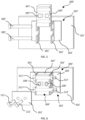
- FIG. 1 An aircraft wing structure 100 according to a first embodiment of the invention are shown in FIG. 1 .
- the aircraft wing structure 100 is configured to form part of a wing 501 of the aircraft 500 shown in FIG. 2 , and comprises a rear spar 101 and a systems module 200.
- the rear spar is configured to form part of the wing box of the aircraft wing 501.
- Other embodiments of the invention may alternatively or additionally comprise a front spar.
- the aircraft wing structure may form part of the aircraft wing, while in other embodiments the aircraft wing structure may not yet form part of the construction of a completed aircraft wing.
- the systems module 200 comprises various electronic systems and associated cable raceways which have been integrated into a single module 200 that can be constructed separately from the spar 101, and which is configured to be installed in a relatively simple installation process, as will be described in more detail below. While the systems module 200 comprises electronic systems, in other embodiments the systems module may alternatively or additionally comprise hydraulic systems or bleed air. In some embodiments the systems module may include line replacement items, which must be replaced at key service intervals.
- the systems module 200 is releasably secured to the spar 101 via a plurality of brackets 300 which are spaced apart along the spar 101 in a span-wise direction, as shown in FIG. 1 .
- One of the brackets 300 is shown in isolation in FIG. 3 .
- the bracket 300 is formed by a body having a generally U-shaped cross-section formed by two extending arms 301 connected by a base 303 which extends between the arms 301, as can be best seen in the cross-sectional view of FIG. 4 .
- the bracket 300 is bolted to a first side 103 of the spar 101 by fasteners 107 which extend through the base 303 of the bracket 300 and through the spar 101.
- the second, opposite side 105 of the spar 101 forms a wall of a fuel tank 109 of the aircraft wing structure 100 such that the fasteners 107 penetrate the fuel tank 109.
- the systems module 200 is secured to the each of the brackets 300 via a raceway plate 201 comprising a plate portion 203 that carries a plurality of electrical cables 205.
- the plate portion 203 is formed with a plurality of holes so that the plate portion 203 can be bolted to the bracket 300 using fasteners 207.
- the raceway plate 201 is placed onto the distal ends of the arms 301 of the bracket 300 so that the raceyway plate is oriented substantially parallel with the base 303.
- the bolts 211 of the fasteners pass through the holes in the raceway plates and into corresponding holes formed in the distal ends of the arms of the bracket 301.
- Each of the bolts 211 engage with a barrel nut 209 which is situated within an opening 305 formed in a side of the bracket 300.
- the size of each of the openings 305 is such that barrel nuts 209 cannot rotate within the openings 305 when the bolt 211 of the fastener 207 is screwed into or out of the barrel nut 209. Accordingly, when fastening and unfastening each of the fasteners 207, there is no need to access the barrel nut 209 with a tool.
- the use of fasteners 207 comprising barrel nuts 209 is therefore advantageous because it simplifies fastening and unfastening of the fasteners 207, and removes the design constraint of being needing to be able to access the nut of the fastener with a tool.
- fasteners comprising conventional nuts, or other methods of releasably securing the systems module to the aircraft structure may of course be used.
- other embodiments of the invention may use alternative mountable members of the systems module instead of raceway plates.
- a mountable member of the systems module may be configured to clip into the bracket, or vice versa, or the systems module may be retained in position upon the bracket by pins or a clasp arrangement.
- the embodiment of the invention described above facilitates modular wing construction, whereby the spar 101 and the systems module 200 can be constructed in parallel, following which the systems module 200 can be installed upon the brackets 300 in a relatively quick and straightforward manner. This potentially enables a reduction in the time taken to manufacture a wing when compared to prior art methods where the spar is constructed and then each of the electronic systems are separately installed upon the wing structure. Additionally, because the systems module 200 is releaseably secured to the bracket 300, when it becomes necessary to remove the systems module 200 from the aircraft wing, for example during servicing or for replacement, there is no need to break the seal of the fuel tank because there is no need to remove the spar fasteners. The bracket 300 can effectively be left permanently mounted to the spar 101.
- brackets 300' are adhesively bonded to the spar 101', as shown in FIG. 5 and FIG. 6 .
- Adhesively bonding the brackets 300' to the spar 101', as opposed to mechanically fastening the brackets using fasteners, provides an advantage of avoiding having to provide holes in the spar 101'.
- the brackets 300' comprise a base portion 302' comprising a base plate 303' which is co-bonded to the spar 101', and two parallel arms 301' which are spaced apart and extend perpendicularly from the base plate 303', away from the spar 101'.
- the brackets 300' further comprise a generally cuboidal mounting block 307' which is removably mounted between the arms 301' of the base portion via fasteners 309' which pass through each of the arms 301' and through the mounting block 307'.
- the systems module 200' of the second embodiment of the invention is realeasably secured to the each of the mounting blocks 307' via a plate 201' of the systems module 200'.
- the plate 201' is formed with a plurality of holes so that the plate 201' can be bolted to the bracket 300' using fasteners 207'.
- the plate 201' is placed onto the mounting block 307' of the bracket 300' and is removably mounted to the mounting block 307' using fasteners 207'.
- the bolts 211' of the fasteners 207' pass through the holes in the plate 201' and into corresponding holes formed in the mounting block 307'.
- Each of the bolts 211' engage with a barrel nut 209' which is situated within an opening 305' formed in a side of the mounting block 307'.
- the size of each of the openings 305' is such that barrel nuts 209' cannot rotate within the openings 305' when the bolt 211' of the fastener 207' is screwed into or out of the barrel nut 209'. Accordingly, when fastening and unfastening each of the fasteners 207', there is no need to access the barrel nut 209' with a tool.
- other methods of releasably secured the systems module to the aircraft structure may of course be used.
- a mountable member of the systems module may be configured to clip into the mounting block, or vice versa, or the systems module may be retained in position upon the mounting block by pins or a clasp arrangement.
- the bracket 300' arrangement of the second embodiment of the invention therefore provides an advantageous way of mounting a systems module to the spar 101' of the aircraft wing where is it undesirable to use fasteners.
- the use of the bracket 300' can avoid the use of fasteners which penetrate a fuel tank.
- the base portion 302' of the bracket 300' can be left permanently mounted to the spar 101 because the systems module 200' is releaseably secured to the base portion 302' via the mounting block 307', which serves as an intermediate member between the systems module 200' and the base portion 302'.
- the systems module 200' can be removed from the aircraft wing by either unfastening the plate 201' from the mounting block 307' or by unfastening the mounting block 307' from the base portion 302'.
- the base portion 302' of the bracket 300' is bonded to the spar, and therefore not easily removable, it may be preferable to reduce wear and tear of the base portion 302 and leave the mounting block 307' semi-permanently mounted to the base portion 302'.
- the mounting block 307' can then be replaced in the event that it becomes damaged or overly worn from repeated fastening and unfastening of the systems module 200' from the mounting block 307'.
- an aspect of the invention is that it provides, in its broadest sense, a wing structure wherein a systems module is removably mounted to a spar via plurality of brackets.
- This aspect of the invention is not itself limited to the types of bracket described above in relation to the first and second embodiments of the invention.
- the skilled person will be aware of other types of bracket which are suitable for use in removably mounting a systems module.
- a bracket of the type described with respect to the first embodiment of the invention could be bonded to the spar and that a bracket of the type described with respect to the second embodiment of the invention could be mechanically fastened to the spar.
Landscapes
- Engineering & Computer Science (AREA)
- Aviation & Aerospace Engineering (AREA)
- Mechanical Engineering (AREA)
- Connection Of Plates (AREA)
- Cooling, Air Intake And Gas Exhaust, And Fuel Tank Arrangements In Propulsion Units (AREA)
Abstract
Description
- The present disclosure relates to the construction of aircraft wings. More particularly, but not exclusively, the invention relates to an aircraft wing structure comprising a spar and a systems module releasably secured to the spar. The invention also concerns methods of installation and removal of said systems modules.
- A prior art method of wing manufacture comprises construction of the structural elements of the wing, such as the wing box, and then equipping of individual systems components to the wing structure. A disadvantage of that method is that construction of the structural elements of the wing must be completed before work can begin on the systems. Additionally, the individual placement of the systems upon the wing structure can make their removal for servicing time consuming.
- Additionally, some prior art wing constructions comprise systems which are installed such that their removal requires the seal of the fuel tank to be broken. Breaking the seal of the fuel tank is complex and time consuming, and is therefore highly undesirable.
- The present invention seeks to mitigate the above-mentioned problems. Alternatively or additionally, the present invention seeks to provide an improved aircraft wing structure and methods relating thereto.
- The present invention provides, according to a first aspect, an aircraft wing structure comprising a spar and a systems module. A plurality of brackets is mounted upon the spar and the systems module is releasably secured to each bracket of the plurality of brackets on a first side of the spar. The second, opposite side of the spar is configured to define a wall of a fuel tank of an aircraft wing.
- The aircraft wing structure according to the first aspect of the invention allows for the systems module to be separately constructed from and in parallel with the spar and other structural elements of the wing structure, and then installed in a relatively simple installation procedure by releasably securing the systems module to the brackets. The modular wing construction of the invention thereby simplifies and speeds up the process of wing manufacture when compared to prior art methods which require the structural and systems elements of the aircraft wing to be constructed in series. This arrangement is of course also advantageous from a service and maintenance perspective, because it allows for the systems module to be easily removed from the spar structure in the event that it needs to be serviced or replaced.
- The aircraft wing structure of the first aspect of the invention is also configured to form part of an aircraft wing which is arranged such that the systems module can be conveniently installed or removed from the aircraft wing without having to break the fuel tank seal. This is achieved by releasably securing the systems module to the brackets situated on the spar such that the brackets themselves do not need to be removed in order to remove the systems module from the aircraft wing.
- The brackets may be spaced apart in a spanwise direction along the spar. The plurality of brackets may comprise two, three, or four brackets. However, it is within the scope of the invention for the plurality of brackets to comprise more than four brackets. The spar may be a front or rear spar of the aircraft wing structure. One or more of the brackets may be mounted directly upon the spar. Alternatively, one or more of the brackets may be indirectly mounted upon the spar via an intermediate structure.
- The systems module may in principle comprise any aircraft system, but preferably the systems module comprises aircraft systems for which easy removal is advantageous. For example, the systems module may comprise electronic or hydraulic systems, or bleed air. In some embodiments the systems module may comprise line replacement items which must be replaced at key service intervals.
- One or more of the brackets of the plurality of brackets may be fastened to the spar by a fastener. A bolt of the fastener may pass through the spar such that, when the aircraft wing structure forms part of an aircraft wing, an end of the fastener is situated within the fuel tank of the aircraft wing. For example, the bracket may be mounted directly to a front or rear spar which defines a wall of a fuel tank of the aircraft wing structure so that, by penetrating the spar, the fastener penetrates the fuel tank. However, because the systems module is releasably secured to the brackets of the aircraft wing structure, there is no need to remove the brackets from the spar in the event that it becomes necessary to dismount the systems module from the spar. Accordingly, the inside of the fuel tank does not need to be accessed in order to remove the systems module from the spar and the bracket can be effectively left permanently mounted to the structure of the aircraft wing, should that be desirable.
- Alternatively or additionally, one or more of the brackets may be bonded to the spar. A bracket may be bonded directly to the first side of the spar. The brackets may be adhesively bonded to the aircraft structure using a co-bonding process or a co-curing process. Bonding the bracket to the spar removes the need for holes to be provided in the spar, so this may provide an advantageous means of mounting the bracket to the spar when holes in the spar are undesirable. For example, it is generally undesirable to provide holes in an aircraft fuel tank so, where the housing is to be mounted to a structure of the aircraft wing at a location that would necessitate fastener holes to be provided in the fuel tank, it may be desirable to bond the bracket to the structure in order to avoid having to provide such holes.
- One or more of the brackets of the plurality of brackets may comprise a main body and an intermediate member. The systems module may be releasably secured to the intermediate member and the intermediate member may be releasably secured to the main body which may be, for example, a base portion of the bracket. For example, a separate intermediate member may be secured to each bracket and the systems module may be secured to each intermediate member. Alternatively a single intermediate member may be secured to two or more of the brackets of the plurality of brackets. It will be understood by the skilled person that the variety of structures could serve as an appropriate intermediate member.
- Use of an intermediate member may be advantageous where the brackets are effectively permanently installed on the spar, and their removal is difficult or undesirable. For example, if the brackets are bonded to the spar or where removing the brackets may necessitate breaking the fuel tank seal. In these cases, care must be taken to minimise wear or damage to the brackets in order to prolong their lifespan and thereby increase the amount of time the brackets can remain mounted to the spar without removal. Wear or damage to the brackets can be caused by removal or installation of the electronics systems module so, by securing the electronics systems module to an intermediate member, that wear or damage can be instead caused to the intermediate member which can easily be replaced with a new intermediate member should the intermediate member be excessively worn or damaged.
- One of the brackets may comprise a substantially U-shaped portion. The substantially U-shaped portion may form a main body of the bracket. The brackets may comprise a base portion which is mounted upon the spar. The base portion may be in the form of a base plate. The base portion may be adhesively bonded to the spar, or to a structure adjacent the spar. Alternatively or additionally, one or more fasteners may pass through the base portion and through the spar, or a structure adjacent the spar, to fasten the base portion to the spar. Two arm portions of the bracket may extend away from the base portion. The arm portions may be oriented substantially perpendicularly to the base portion. Where the base portion is fastened to the spar using fasteners, the systems module may be fastened to the arms of the base portion using fasteners which are oriented substantially parallel to the arms of the base portion. For example, the fasteners may enter the distal ends of the arms of the base portion. Where the brackets comprise an intermediate member, the intermediate member may be releasably secured between the arms of the base portion. The intermediate member may be releasably secured to the base portion by one or more fasteners which pass through the arms of the base portion and through the intermediate member, said fasteners may be oriented substantially perpendicularly to the direction in which the arms extend.
- The systems module may comprise a plurality of mounting members. Each mounting member of the plurality of mounting members may be releasably secured to a respective one of the brackets of the plurality of brackets. Each mounting member may comprise a raceway module comprising a plate carrying a plurality of electrical cables. The plate may be releasably secured to one or more of the brackets of the plurality of brackets.
- The systems module may be releasably secured to each bracket of the plurality of brackets by a fastener comprising a barrel nut. The barrel nut may be configured to engage with a part of the bracket to prevent rotation of the barrel nut when rotating the bolt within the barrel nut to tighten or untighten the fastener. The fastener may pass through one or more mounting members of the systems module.
- According to a second aspect, the present invention provides an aircraft wing comprising the aircraft wing structure of the first aspect of the invention. The spar of the aircraft wing structure defines a wall of a fuel tank of the aircraft wing.
- According to a third aspect, the present invention provides an aircraft comprising the wing of the second aspect of the invention.
- According to a fourth aspect, the present invention provides a kit of parts suitable for forming an aircraft wing structure. The kit comprises a spar and a systems module, wherein a plurality of brackets is mounted upon the spar, and wherein the systems module is configured to be releasably secured to each bracket of the plurality of brackets on a first side of the spar. The second, opposite side of the spar is configured to define a wall of a fuel tank of an aircraft wing.
- According to a fifth aspect, the present invention provides a method of removing a systems module from an aircraft wing structure. The aircraft wing structure comprises a plurality of brackets mounted upon a spar of the aircraft wing structure, the brackets being positioned on a first side of the spar and the second, opposite side of the spar is configured to define a wall of a fuel tank of an aircraft wing. The systems module is releasably secured to each bracket of the plurality of brackets. The method comprises the step of unsecuring the systems module from each of the brackets and moving the systems module away from the aircraft wing structure. The aircraft wing structure may form part of an aircraft wing. The wing may form part of an aircraft. Alternatively, the method may be performed on a wing structure which does not form part of an aircraft. For example, where the wing structure or wing has been removed from or has not yet been installed on an aircraft.
- According to a sixth aspect, the present invention provides a method of installing a systems module upon a spar of an aircraft wing structure. The aircraft wing structure comprises a plurality of brackets mounted upon a spar of the aircraft wing structure, the brackets being positioned on a first side of the spar and the second, opposite side of the spar is configured to define a wall of a fuel tank of an aircraft wing. The method comprises releasably securing the systems module to each bracket of the plurality of brackets. The wing may form part of an aircraft. Alternatively, the method may be performed on a wing structure which does not form part of an aircraft. For example, where the wing structure or wing has been removed from or has not yet been installed on an aircraft.
- It will of course be appreciated that features described in relation to one aspect of the present invention may be incorporated into other aspects of the present invention. For example, the methods of the fifth or sixth aspects of the invention may incorporate any of the features described with reference to the wing structure of the first aspect of the invention and vice versa.
- Embodiments of the present invention will now be described by way of example only with reference to the accompanying schematic drawings of which:
- FIG. 1
- is a schematic drawing an aircraft wing structure according to a first embodiment of the invention comprising a systems module removably mounted to a wing spar;
- FIG. 2
- shows an aircraft having a wing comprising the aircraft wing structure shown in
FIG.1 ; - FIG. 3
- is a schematic drawing of a bracket of the aircraft wing structure of
FIG. 1 ; - FIG. 4
- is a schematic cross-sectional view of the bracket shown in
FIG. 3 ; - FIG. 5
- is a schematic drawing of a bracket configured for removably mounting a systems module to a spar in an aircraft wing structure according to a second embodiment of the invention, the bracket is shown with its mounting block removed from its base plate; and
- FIG. 6
- is another schematic drawing of the bracket of
FIG. 5 , the bracket is shown with the mounting block in a position ready to be secured to its base plate. - An
aircraft wing structure 100 according to a first embodiment of the invention are shown inFIG. 1 . Theaircraft wing structure 100 is configured to form part of awing 501 of theaircraft 500 shown inFIG. 2 , and comprises arear spar 101 and asystems module 200. The rear spar is configured to form part of the wing box of theaircraft wing 501. Other embodiments of the invention may alternatively or additionally comprise a front spar. In some embodiments of the invention the aircraft wing structure may form part of the aircraft wing, while in other embodiments the aircraft wing structure may not yet form part of the construction of a completed aircraft wing. - The
systems module 200 comprises various electronic systems and associated cable raceways which have been integrated into asingle module 200 that can be constructed separately from thespar 101, and which is configured to be installed in a relatively simple installation process, as will be described in more detail below. While thesystems module 200 comprises electronic systems, in other embodiments the systems module may alternatively or additionally comprise hydraulic systems or bleed air. In some embodiments the systems module may include line replacement items, which must be replaced at key service intervals. - The
systems module 200 is releasably secured to thespar 101 via a plurality ofbrackets 300 which are spaced apart along thespar 101 in a span-wise direction, as shown inFIG. 1 . One of thebrackets 300 is shown in isolation inFIG. 3 . Thebracket 300 is formed by a body having a generally U-shaped cross-section formed by two extendingarms 301 connected by a base 303 which extends between thearms 301, as can be best seen in the cross-sectional view ofFIG. 4 . Thebracket 300 is bolted to afirst side 103 of thespar 101 byfasteners 107 which extend through thebase 303 of thebracket 300 and through thespar 101. As can also been seen inFIG. 4 , the second,opposite side 105 of thespar 101 forms a wall of afuel tank 109 of theaircraft wing structure 100 such that thefasteners 107 penetrate thefuel tank 109. - In the presently described embodiment of the invention, the
systems module 200 is secured to the each of thebrackets 300 via araceway plate 201 comprising aplate portion 203 that carries a plurality ofelectrical cables 205. Theplate portion 203 is formed with a plurality of holes so that theplate portion 203 can be bolted to thebracket 300 usingfasteners 207. As can be seen inFIG. 4 , theraceway plate 201 is placed onto the distal ends of thearms 301 of thebracket 300 so that the raceyway plate is oriented substantially parallel with thebase 303. Thebolts 211 of the fasteners pass through the holes in the raceway plates and into corresponding holes formed in the distal ends of the arms of thebracket 301. Each of thebolts 211 engage with abarrel nut 209 which is situated within anopening 305 formed in a side of thebracket 300. The size of each of theopenings 305 is such thatbarrel nuts 209 cannot rotate within theopenings 305 when thebolt 211 of thefastener 207 is screwed into or out of thebarrel nut 209. Accordingly, when fastening and unfastening each of thefasteners 207, there is no need to access thebarrel nut 209 with a tool. The use offasteners 207 comprisingbarrel nuts 209 is therefore advantageous because it simplifies fastening and unfastening of thefasteners 207, and removes the design constraint of being needing to be able to access the nut of the fastener with a tool. - In other embodiments of the invention, fasteners comprising conventional nuts, or other methods of releasably securing the systems module to the aircraft structure may of course be used. Additionally, other embodiments of the invention may use alternative mountable members of the systems module instead of raceway plates. For example, a mountable member of the systems module may be configured to clip into the bracket, or vice versa, or the systems module may be retained in position upon the bracket by pins or a clasp arrangement.
- The embodiment of the invention described above facilitates modular wing construction, whereby the
spar 101 and thesystems module 200 can be constructed in parallel, following which thesystems module 200 can be installed upon thebrackets 300 in a relatively quick and straightforward manner. This potentially enables a reduction in the time taken to manufacture a wing when compared to prior art methods where the spar is constructed and then each of the electronic systems are separately installed upon the wing structure. Additionally, because thesystems module 200 is releaseably secured to thebracket 300, when it becomes necessary to remove thesystems module 200 from the aircraft wing, for example during servicing or for replacement, there is no need to break the seal of the fuel tank because there is no need to remove the spar fasteners. Thebracket 300 can effectively be left permanently mounted to thespar 101. - In an aircraft wing structure according to a second embodiment of the invention the brackets 300' are adhesively bonded to the spar 101', as shown in
FIG. 5 and FIG. 6 . Adhesively bonding the brackets 300' to the spar 101', as opposed to mechanically fastening the brackets using fasteners, provides an advantage of avoiding having to provide holes in the spar 101'. - The brackets 300' comprise a base portion 302' comprising a base plate 303' which is co-bonded to the spar 101', and two parallel arms 301' which are spaced apart and extend perpendicularly from the base plate 303', away from the spar 101'. The brackets 300' further comprise a generally cuboidal mounting block 307' which is removably mounted between the arms 301' of the base portion via fasteners 309' which pass through each of the arms 301' and through the mounting block 307'.
- The systems module 200' of the second embodiment of the invention is realeasably secured to the each of the mounting blocks 307' via a plate 201' of the systems module 200'. The plate 201' is formed with a plurality of holes so that the plate 201' can be bolted to the bracket 300' using fasteners 207'. As can be seen in
FIG. 6 , the plate 201' is placed onto the mounting block 307' of the bracket 300' and is removably mounted to the mounting block 307' using fasteners 207'. The bolts 211' of the fasteners 207' pass through the holes in the plate 201' and into corresponding holes formed in the mounting block 307'. Each of the bolts 211' engage with a barrel nut 209' which is situated within anopening 305' formed in a side of the mounting block 307'. The size of each of theopenings 305' is such that barrel nuts 209' cannot rotate within theopenings 305' when the bolt 211' of the fastener 207' is screwed into or out of the barrel nut 209'. Accordingly, when fastening and unfastening each of the fasteners 207', there is no need to access the barrel nut 209' with a tool. In other embodiments of the invention other methods of releasably secured the systems module to the aircraft structure may of course be used. For example, a mountable member of the systems module may be configured to clip into the mounting block, or vice versa, or the systems module may be retained in position upon the mounting block by pins or a clasp arrangement. - The bracket 300' arrangement of the second embodiment of the invention therefore provides an advantageous way of mounting a systems module to the spar 101' of the aircraft wing where is it undesirable to use fasteners. For example, the use of the bracket 300' can avoid the use of fasteners which penetrate a fuel tank. The base portion 302' of the bracket 300' can be left permanently mounted to the
spar 101 because the systems module 200' is releaseably secured to the base portion 302' via the mounting block 307', which serves as an intermediate member between the systems module 200' and the base portion 302'. The systems module 200' can be removed from the aircraft wing by either unfastening the plate 201' from the mounting block 307' or by unfastening the mounting block 307' from the base portion 302'. However, because the base portion 302' of the bracket 300' is bonded to the spar, and therefore not easily removable, it may be preferable to reduce wear and tear of thebase portion 302 and leave the mounting block 307' semi-permanently mounted to the base portion 302'. The mounting block 307' can then be replaced in the event that it becomes damaged or overly worn from repeated fastening and unfastening of the systems module 200' from the mounting block 307'. - Whilst the present invention has been described and illustrated with reference to particular embodiments, it will be appreciated by those of ordinary skill in the art that the invention lends itself to many different variations not specifically illustrated herein. For example, it should be understood that an aspect of the invention is that it provides, in its broadest sense, a wing structure wherein a systems module is removably mounted to a spar via plurality of brackets. This aspect of the invention is not itself limited to the types of bracket described above in relation to the first and second embodiments of the invention. The skilled person will be aware of other types of bracket which are suitable for use in removably mounting a systems module. Additionally, it should be noted that a bracket of the type described with respect to the first embodiment of the invention could be bonded to the spar and that a bracket of the type described with respect to the second embodiment of the invention could be mechanically fastened to the spar.
- Where in the foregoing description, integers or elements are mentioned which have known, obvious or foreseeable equivalents, then such equivalents are herein incorporated as if individually set forth. Reference should be made to the claims for determining the true scope of the present invention, which should be construed so as to encompass any such equivalents. It will also be appreciated by the reader that integers or features of the invention that are described as preferable, advantageous, convenient or the like are optional and do not limit the scope of the independent claims. Moreover, it is to be understood that such optional integers or features, whilst of possible benefit in some embodiments of the invention, may not be desirable, and may therefore be absent, in other embodiments.
Claims (10)
- An aircraft wing structure comprising a spar and a systems module, wherein a plurality of brackets is mounted upon the spar, and wherein the systems module is releasably secured to each bracket of the plurality of brackets on a first side of the spar and the second, opposite side of the spar is configured to define a wall of a fuel tank of an aircraft wing, wherein the systems module comprises a raceway module comprising a plate carrying a plurality of electrical cables, and wherein the plate is releasably secured to one or more of the brackets of the plurality of brackets.
- The aircraft wing structure of claim 1, wherein one or more of the brackets of the plurality of brackets is fastened to the spar by a fastener configured such that, when the aircraft wing structure forms part of an aircraft wing, an end of the fastener is situated within the fuel tank of the aircraft wing.
- The aircraft wing structure of claim 1 or claim 2, wherein at least one of the brackets of the plurality of brackets is adhesively bonded to the spar.
- The aircraft wing structure of any preceding claim, wherein at least one of the brackets of the plurality of brackets comprises a main body and an intermediate member, and wherein the systems module is releasably secured to the intermediate member and the intermediate member is releasably secured to the main body.
- The aircraft wing structure of any preceding claim, wherein the systems module is releasably secured to at least one bracket of the plurality of brackets by a fastener comprising a barrel nut, and wherein the barrel nut is configured to engage with a part of the bracket to prevent rotation of the barrel nut when rotating the bolt within the barrel nut to tighten or untighten the fastener.
- An aircraft wing comprising an aircraft wing structure according to any preceding claim, wherein the spar of the aircraft wing structure defines a wall of a fuel tank of the aircraft wing.
- An aircraft comprising a wing according to claim 6.
- A kit of parts suitable for forming an aircraft wing structure, the kit comprising a spar and a systems module comprising a plate carrying a plurality of electrical cables, wherein a plurality of brackets is mounted upon the spar, and wherein the systems module is configured to be releasably secured to each bracket of the plurality of brackets on a first side of the spar, the plate of the systems module being configured to be releasably secured to at least one of the brackets of the plurality of brackets, and the second, opposite side of the spar is configured to define a wall of a fuel tank of an aircraft wing.
- A method of removing a systems module from an aircraft wing structure, the systems module comprising a plate carrying a plurality of electrical cables, wherein the aircraft wing structure comprises a plurality of brackets mounted upon a spar of the aircraft wing structure, the brackets being positioned on a first side of the spar and the second, opposite side of the spar is configured to define a wall of a fuel tank of an aircraft wing, wherein the systems module is releasably secured to each bracket of the plurality of brackets and the plate of the systems module is releasably secured to at least one of the brackets of the plurality of brackets, and wherein the method comprises the step of releasing the systems module from each of the brackets and moving the systems module away from the aircraft wing structure.
- A method of installing a systems module upon a spar of an aircraft wing structure, the systems module comprising a plate carrying a plurality of electrical cables, wherein the aircraft wing structure comprises a plurality of brackets mounted upon a spar of the aircraft wing structure, the brackets being positioned on a first side of the spar and the second, opposite side of the spar is configured to define a wall of a fuel tank of an aircraft wing, and wherein the method comprises releasably securing the systems module to each bracket of the plurality of brackets, including releasably securing the plate of the systems module to at least one of the brackets of the plurality of brackets.
Priority Applications (1)
| Application Number | Priority Date | Filing Date | Title |
|---|---|---|---|
| EP26158883.4A EP4725830A2 (en) | 2022-01-31 | 2023-01-26 | Improvements relating to wing construction |
Applications Claiming Priority (1)
| Application Number | Priority Date | Filing Date | Title |
|---|---|---|---|
| GB2201217.3A GB2615310A (en) | 2022-01-31 | 2022-01-31 | Improvements relating to wing construction |
Related Child Applications (2)
| Application Number | Title | Priority Date | Filing Date |
|---|---|---|---|
| EP26158883.4A Division EP4725830A2 (en) | 2022-01-31 | 2023-01-26 | Improvements relating to wing construction |
| EP26158883.4A Division-Into EP4725830A2 (en) | 2022-01-31 | 2023-01-26 | Improvements relating to wing construction |
Publications (2)
| Publication Number | Publication Date |
|---|---|
| EP4219294A1 true EP4219294A1 (en) | 2023-08-02 |
| EP4219294B1 EP4219294B1 (en) | 2026-04-01 |
Family
ID=80621249
Family Applications (2)
| Application Number | Title | Priority Date | Filing Date |
|---|---|---|---|
| EP26158883.4A Pending EP4725830A2 (en) | 2022-01-31 | 2023-01-26 | Improvements relating to wing construction |
| EP23153389.4A Active EP4219294B1 (en) | 2022-01-31 | 2023-01-26 | Improvements relating to wing construction |
Family Applications Before (1)
| Application Number | Title | Priority Date | Filing Date |
|---|---|---|---|
| EP26158883.4A Pending EP4725830A2 (en) | 2022-01-31 | 2023-01-26 | Improvements relating to wing construction |
Country Status (4)
| Country | Link |
|---|---|
| US (1) | US12077287B2 (en) |
| EP (2) | EP4725830A2 (en) |
| CN (1) | CN116513446A (en) |
| GB (1) | GB2615310A (en) |
Citations (5)
| Publication number | Priority date | Publication date | Assignee | Title |
|---|---|---|---|---|
| EP0184931A2 (en) * | 1984-12-08 | 1986-06-18 | British Aerospace Public Limited Company | Cable conduit system for vehicles |
| US20090218446A1 (en) * | 2008-02-29 | 2009-09-03 | Airbus Uk Limited | Aircraft structure with hinge rib assembly |
| EP2360801A2 (en) * | 2010-02-16 | 2011-08-24 | Airbus Operations Limited | Aircraft raceway mounting and clamping apparatus |
| US20200207459A1 (en) * | 2018-12-31 | 2020-07-02 | Airbus Operations Gmbh | Connection rod |
| GB2587684A (en) * | 2019-10-02 | 2021-04-07 | Advanced Mobility Res And Development Ltd | Systems, arrangements, structures and methods for aircraft |
Family Cites Families (12)
| Publication number | Priority date | Publication date | Assignee | Title |
|---|---|---|---|---|
| FR2774358B1 (en) | 1998-02-04 | 2000-04-21 | Aerospatiale | HANGING DEVICE OF AN AIRCRAFT ENGINE |
| GB0624778D0 (en) * | 2006-12-12 | 2007-01-17 | Airbus Uk Ltd | Celebrity routing clip |
| US9040821B2 (en) | 2010-10-29 | 2015-05-26 | Airbus Operations Limited | Aircraft cable routing harness |
| JP5751871B2 (en) * | 2011-03-10 | 2015-07-22 | 三菱重工業株式会社 | Fuel tank |
| GB201110973D0 (en) * | 2011-06-28 | 2011-08-10 | Airbus Operations Ltd | Bracket |
| EP2879252B1 (en) * | 2013-11-28 | 2016-02-03 | AIRBUS HELICOPTERS DEUTSCHLAND GmbH | Raceway for fastening, guiding and/or protecting electric cable means |
| GB2557274A (en) * | 2016-12-02 | 2018-06-20 | Airbus Operations Ltd | Aerofoil structure components |
| ES2800182T3 (en) | 2017-07-13 | 2020-12-28 | Airbus Operations Sl | Structural arrangement of the box for an aircraft and its manufacturing process |
| US11161594B2 (en) * | 2019-09-25 | 2021-11-02 | The Boeing Company | Flap support breakaway and fail safety configuration |
| GB2593880A (en) * | 2020-03-31 | 2021-10-13 | Airbus Operations Ltd | An aircraft wing box |
| US11643184B2 (en) * | 2020-07-29 | 2023-05-09 | The Boeing Company | Wing assembly having discretely stiffened composite wing panels |
| GB2600409B (en) * | 2020-10-27 | 2022-11-02 | Airbus Operations Ltd | Fuel tank assemblies |
-
2022
- 2022-01-31 GB GB2201217.3A patent/GB2615310A/en active Pending
-
2023
- 2023-01-26 EP EP26158883.4A patent/EP4725830A2/en active Pending
- 2023-01-26 EP EP23153389.4A patent/EP4219294B1/en active Active
- 2023-01-31 US US18/162,303 patent/US12077287B2/en active Active
- 2023-01-31 CN CN202310091876.0A patent/CN116513446A/en active Pending
Patent Citations (5)
| Publication number | Priority date | Publication date | Assignee | Title |
|---|---|---|---|---|
| EP0184931A2 (en) * | 1984-12-08 | 1986-06-18 | British Aerospace Public Limited Company | Cable conduit system for vehicles |
| US20090218446A1 (en) * | 2008-02-29 | 2009-09-03 | Airbus Uk Limited | Aircraft structure with hinge rib assembly |
| EP2360801A2 (en) * | 2010-02-16 | 2011-08-24 | Airbus Operations Limited | Aircraft raceway mounting and clamping apparatus |
| US20200207459A1 (en) * | 2018-12-31 | 2020-07-02 | Airbus Operations Gmbh | Connection rod |
| GB2587684A (en) * | 2019-10-02 | 2021-04-07 | Advanced Mobility Res And Development Ltd | Systems, arrangements, structures and methods for aircraft |
Also Published As
| Publication number | Publication date |
|---|---|
| GB2615310A (en) | 2023-08-09 |
| CN116513446A (en) | 2023-08-01 |
| US12077287B2 (en) | 2024-09-03 |
| EP4725830A2 (en) | 2026-04-15 |
| US20230242241A1 (en) | 2023-08-03 |
| GB202201217D0 (en) | 2022-03-16 |
| EP4219294B1 (en) | 2026-04-01 |
Similar Documents
| Publication | Publication Date | Title |
|---|---|---|
| JP6534244B2 (en) | How to attach winglet fittings and split winglets to a wing | |
| CN101443238B (en) | Device for attaching an aircraft engine | |
| JP4679568B2 (en) | Support device for galley | |
| CN206564271U (en) | Structure of a battery pack for an electric vehicle and an electric vehicle chassis | |
| EP0755830B1 (en) | Air bag mounting system | |
| US9156566B2 (en) | Securing plate and longitudinal handling member for a one-piece aircraft propulsion unit | |
| US20100322782A1 (en) | Nosecone bolt access and aerodynamic leakage baffle | |
| EP3031647B1 (en) | Structure for mounting battery on vehicle | |
| US9731581B2 (en) | Vehicle door and door module with multi-portion door carrier | |
| US8800916B2 (en) | Device for attaching an aircraft engine, comprising blocks for clamping an engine attachment with a wedge effect | |
| CA2500666A1 (en) | Quick change window assembly | |
| US8763264B2 (en) | Interface and a method for mounting together a piece of equipment and a rotary drive source in a rotorcraft power plant | |
| WO2019016081A1 (en) | accumulator | |
| DK2549563T3 (en) | System of a battery tray and a tray recording for mounting the battery tray in a battery box of a wind power plant | |
| US20230242241A1 (en) | Relating to wing construction | |
| WO2024032657A1 (en) | Compressor unit for vehicle | |
| US6585287B1 (en) | Roof rail air bag assembly and method of installation | |
| US20180231041A1 (en) | Attachment bracket and support assembly | |
| US9874147B2 (en) | V-band clamp with integral mount plate | |
| US10329958B2 (en) | Casing structure interposed between the engine and the nacelle having a mounting plate with bolts | |
| CN219152765U (en) | Narrow space fastener dismouting device | |
| US8226036B2 (en) | ECU mounting system for a light aircraft | |
| EP3867143A1 (en) | Method of manufacturing an aerodynamic structure | |
| US12337771B2 (en) | Motor vehicle and method for mounting a housing on a shell of a motor vehicle | |
| CN218708617U (en) | Integral type passenger train air conditioner hoist device |
Legal Events
| Date | Code | Title | Description |
|---|---|---|---|
| PUAI | Public reference made under article 153(3) epc to a published international application that has entered the european phase |
Free format text: ORIGINAL CODE: 0009012 |
|
| STAA | Information on the status of an ep patent application or granted ep patent |
Free format text: STATUS: THE APPLICATION HAS BEEN PUBLISHED |
|
| AK | Designated contracting states |
Kind code of ref document: A1 Designated state(s): AL AT BE BG CH CY CZ DE DK EE ES FI FR GB GR HR HU IE IS IT LI LT LU LV MC ME MK MT NL NO PL PT RO RS SE SI SK SM TR |
|
| STAA | Information on the status of an ep patent application or granted ep patent |
Free format text: STATUS: REQUEST FOR EXAMINATION WAS MADE |
|
| 17P | Request for examination filed |
Effective date: 20240130 |
|
| RBV | Designated contracting states (corrected) |
Designated state(s): AL AT BE BG CH CY CZ DE DK EE ES FI FR GB GR HR HU IE IS IT LI LT LU LV MC ME MK MT NL NO PL PT RO RS SE SI SK SM TR |
|
| STAA | Information on the status of an ep patent application or granted ep patent |
Free format text: STATUS: EXAMINATION IS IN PROGRESS |
|
| 17Q | First examination report despatched |
Effective date: 20250103 |
|
| GRAP | Despatch of communication of intention to grant a patent |
Free format text: ORIGINAL CODE: EPIDOSNIGR1 |
|
| STAA | Information on the status of an ep patent application or granted ep patent |
Free format text: STATUS: GRANT OF PATENT IS INTENDED |
|
| INTG | Intention to grant announced |
Effective date: 20251103 |
|
| GRAS | Grant fee paid |
Free format text: ORIGINAL CODE: EPIDOSNIGR3 |
|
| GRAA | (expected) grant |
Free format text: ORIGINAL CODE: 0009210 |
|
| STAA | Information on the status of an ep patent application or granted ep patent |
Free format text: STATUS: THE PATENT HAS BEEN GRANTED |
|
| AK | Designated contracting states |
Kind code of ref document: B1 Designated state(s): AL AT BE BG CH CY CZ DE DK EE ES FI FR GB GR HR HU IE IS IT LI LT LU LV MC ME MK MT NL NO PL PT RO RS SE SI SK SM TR |
|
| REG | Reference to a national code |
Ref country code: CH Ref legal event code: F10 Free format text: ST27 STATUS EVENT CODE: U-0-0-F10-F00 (AS PROVIDED BY THE NATIONAL OFFICE) Effective date: 20260401 Ref country code: GB Ref legal event code: FG4D |
|
| REG | Reference to a national code |
Ref country code: IE Ref legal event code: FG4D |
|
| REG | Reference to a national code |
Ref country code: DE Ref legal event code: R096 Ref document number: 602023014253 Country of ref document: DE |