EP4219187A1 - Grip for a writing implement - Google Patents
Grip for a writing implement Download PDFInfo
- Publication number
- EP4219187A1 EP4219187A1 EP22154263.2A EP22154263A EP4219187A1 EP 4219187 A1 EP4219187 A1 EP 4219187A1 EP 22154263 A EP22154263 A EP 22154263A EP 4219187 A1 EP4219187 A1 EP 4219187A1
- Authority
- EP
- European Patent Office
- Prior art keywords
- grip
- liquid
- channel
- liquid reservoir
- valve
- Prior art date
- Legal status (The legal status is an assumption and is not a legal conclusion. Google has not performed a legal analysis and makes no representation as to the accuracy of the status listed.)
- Pending
Links
- 239000007788 liquid Substances 0.000 claims abstract description 224
- 238000009792 diffusion process Methods 0.000 claims abstract description 64
- 239000003205 fragrance Substances 0.000 claims abstract description 64
- 238000004891 communication Methods 0.000 claims abstract description 15
- 230000008020 evaporation Effects 0.000 claims abstract description 8
- 238000001704 evaporation Methods 0.000 claims abstract description 8
- 230000004044 response Effects 0.000 claims abstract description 4
- 239000000758 substrate Substances 0.000 claims description 22
- 238000010146 3D printing Methods 0.000 claims description 7
- 238000000034 method Methods 0.000 claims description 7
- 238000004806 packaging method and process Methods 0.000 claims description 6
- 238000004519 manufacturing process Methods 0.000 claims description 5
- 239000012528 membrane Substances 0.000 claims description 3
- 239000011800 void material Substances 0.000 description 8
- 238000006073 displacement reaction Methods 0.000 description 5
- 239000003570 air Substances 0.000 description 4
- 239000000463 material Substances 0.000 description 4
- -1 polyethylene Polymers 0.000 description 4
- 230000006870 function Effects 0.000 description 3
- 239000004698 Polyethylene Substances 0.000 description 2
- 239000004743 Polypropylene Substances 0.000 description 2
- 235000019568 aromas Nutrition 0.000 description 2
- 238000000222 aromatherapy Methods 0.000 description 2
- 238000013270 controlled release Methods 0.000 description 2
- 230000001276 controlling effect Effects 0.000 description 2
- 229920001971 elastomer Polymers 0.000 description 2
- 239000000806 elastomer Substances 0.000 description 2
- 230000000670 limiting effect Effects 0.000 description 2
- 229920001707 polybutylene terephthalate Polymers 0.000 description 2
- 229920000139 polyethylene terephthalate Polymers 0.000 description 2
- 239000005020 polyethylene terephthalate Substances 0.000 description 2
- 239000011148 porous material Substances 0.000 description 2
- 238000005086 pumping Methods 0.000 description 2
- 239000012858 resilient material Substances 0.000 description 2
- 230000000717 retained effect Effects 0.000 description 2
- 239000012855 volatile organic compound Substances 0.000 description 2
- 241000506680 Haemulon melanurum Species 0.000 description 1
- 239000000853 adhesive Substances 0.000 description 1
- 230000001070 adhesive effect Effects 0.000 description 1
- 239000012080 ambient air Substances 0.000 description 1
- 238000013459 approach Methods 0.000 description 1
- 230000004888 barrier function Effects 0.000 description 1
- 230000015572 biosynthetic process Effects 0.000 description 1
- 239000000919 ceramic Substances 0.000 description 1
- 230000006835 compression Effects 0.000 description 1
- 238000007906 compression Methods 0.000 description 1
- 238000012864 cross contamination Methods 0.000 description 1
- 230000001419 dependent effect Effects 0.000 description 1
- 238000009826 distribution Methods 0.000 description 1
- 238000005538 encapsulation Methods 0.000 description 1
- 230000007613 environmental effect Effects 0.000 description 1
- 239000000835 fiber Substances 0.000 description 1
- 238000010438 heat treatment Methods 0.000 description 1
- 230000001939 inductive effect Effects 0.000 description 1
- 238000002347 injection Methods 0.000 description 1
- 239000007924 injection Substances 0.000 description 1
- 238000001746 injection moulding Methods 0.000 description 1
- 230000015654 memory Effects 0.000 description 1
- 239000006262 metallic foam Substances 0.000 description 1
- 230000036961 partial effect Effects 0.000 description 1
- 239000002304 perfume Substances 0.000 description 1
- 230000002572 peristaltic effect Effects 0.000 description 1
- 229920000728 polyester Polymers 0.000 description 1
- 229920000573 polyethylene Polymers 0.000 description 1
- 229920001155 polypropylene Polymers 0.000 description 1
- 229920001296 polysiloxane Polymers 0.000 description 1
- 230000001681 protective effect Effects 0.000 description 1
- 230000002829 reductive effect Effects 0.000 description 1
- 230000001105 regulatory effect Effects 0.000 description 1
- 238000003860 storage Methods 0.000 description 1
- XLYOFNOQVPJJNP-UHFFFAOYSA-N water Substances O XLYOFNOQVPJJNP-UHFFFAOYSA-N 0.000 description 1
Images


Classifications
-
- B—PERFORMING OPERATIONS; TRANSPORTING
- B43—WRITING OR DRAWING IMPLEMENTS; BUREAU ACCESSORIES
- B43K—IMPLEMENTS FOR WRITING OR DRAWING
- B43K23/00—Holders or connectors for writing implements; Means for protecting the writing-points
- B43K23/008—Holders comprising finger grips
-
- A—HUMAN NECESSITIES
- A45—HAND OR TRAVELLING ARTICLES
- A45D—HAIRDRESSING OR SHAVING EQUIPMENT; EQUIPMENT FOR COSMETICS OR COSMETIC TREATMENTS, e.g. FOR MANICURING OR PEDICURING
- A45D34/00—Containers or accessories specially adapted for handling liquid toiletry or cosmetic substances, e.g. perfumes
- A45D34/02—Scent flasks, e.g. with evaporator
-
- B—PERFORMING OPERATIONS; TRANSPORTING
- B05—SPRAYING OR ATOMISING IN GENERAL; APPLYING FLUENT MATERIALS TO SURFACES, IN GENERAL
- B05B—SPRAYING APPARATUS; ATOMISING APPARATUS; NOZZLES
- B05B11/00—Single-unit hand-held apparatus in which flow of contents is produced by the muscular force of the operator at the moment of use
- B05B11/0005—Components or details
- B05B11/0062—Outlet valves actuated by the pressure of the fluid to be sprayed
- B05B11/007—Outlet valves actuated by the pressure of the fluid to be sprayed being opened by deformation of a sealing element made of resiliently deformable material, e.g. flaps, skirts, duck-bill valves
-
- B—PERFORMING OPERATIONS; TRANSPORTING
- B05—SPRAYING OR ATOMISING IN GENERAL; APPLYING FLUENT MATERIALS TO SURFACES, IN GENERAL
- B05B—SPRAYING APPARATUS; ATOMISING APPARATUS; NOZZLES
- B05B11/00—Single-unit hand-held apparatus in which flow of contents is produced by the muscular force of the operator at the moment of use
- B05B11/01—Single-unit hand-held apparatus in which flow of contents is produced by the muscular force of the operator at the moment of use characterised by the means producing the flow
- B05B11/02—Membranes or pistons acting on the contents inside the container, e.g. follower pistons
-
- B—PERFORMING OPERATIONS; TRANSPORTING
- B05—SPRAYING OR ATOMISING IN GENERAL; APPLYING FLUENT MATERIALS TO SURFACES, IN GENERAL
- B05B—SPRAYING APPARATUS; ATOMISING APPARATUS; NOZZLES
- B05B11/00—Single-unit hand-held apparatus in which flow of contents is produced by the muscular force of the operator at the moment of use
- B05B11/01—Single-unit hand-held apparatus in which flow of contents is produced by the muscular force of the operator at the moment of use characterised by the means producing the flow
- B05B11/04—Deformable containers producing the flow, e.g. squeeze bottles
-
- B—PERFORMING OPERATIONS; TRANSPORTING
- B43—WRITING OR DRAWING IMPLEMENTS; BUREAU ACCESSORIES
- B43K—IMPLEMENTS FOR WRITING OR DRAWING
- B43K29/00—Combinations of writing implements with other articles
Definitions
- the embodiments described concern a grip for use with a writing implement, a writing implement comprising the grip, a kit of parts, and a method of assembly.
- a scented writing instrument emits an aroma, such as a coffee or perfume aroma.
- Scented writing instruments can be used for educational purposes, where an attractively scented pen can attract the interest of a child learning to write.
- scented writing instruments with a range of different scents enable the blind, or partially sighted, to distinguish between different pen types.
- Scented writing instruments have applications in aromatherapy, where scents enable a user to relax, or to instigate memories, or to stimulate creativity (dependent on the aromatherapy scent applied).
- Conventional scented writing instruments typically comprise a body element which has the liquid scent impregnated into the body element, or permanently exposed to the atmosphere via a micro grille or hole. Scented writing instruments may, therefore, be further improved.
- a grip for use with a writing implement.
- the grip comprises a liquid reservoir comprising a volatile liquid, a user actuator configured to pressurize the volatile liquid in the liquid reservoir based on a force applied by a user of the grip, and a liquid transfer member comprising at least one channel configured to provide a liquid transfer path out of the liquid reservoir.
- the grip further comprises a fragrance diffusion member in fluidic communication with the at least one channel. In use, an amount of volatile liquid is delivered to the fragrance diffusion member via the at least one channel in response to the user applying a force to the user actuator, and the grip is configured to release an aroma upon evaporation of the volatile liquid from the fragrance diffusion member.
- the grips disclosed herein are also compatible with accepted packaging and distribution practices.
- a grip, or a writing implement comprising the grip When a grip, or a writing implement comprising the grip, is packaged, or held in a user's pencil case, it does not emit aroma, which could otherwise become distracting in storage cupboards or warehouses.
- the need for providing a hermetically sealed package is removed, thus simplifying and reducing cost and environmental impact of the packaging needed. If a plurality of grips are distributed in the same package, the cross-contamination of aromas (which may result in an unpleasant smell) from one grip to another is avoided.
- the need to provide a complicated internal seal inside the packaging between at least two pens having mutually different scents is removed.
- the grip may be sold integrated with a writing implement, or as a retrofit option, enabling the grip to be used with a wide range of existing writing implements according to the user's choice.
- the integrated liquid reservoir, liquid channel, liquid transfer member, and fragrance diffusion member may be amenable to partial, or full, 3D printing. Therefore, the controlled release, and evaporation, of a volatile liquid in a fragrance emitting grip is enabled.
- a writing implement comprising a writing implement body, and a permanent or removable grip according to the first aspect.
- a method comprising assembling together at least (i) a liquid reservoir, (ii) a liquid transfer member comprising at least one channel configured to provide a liquid transfer path out of the liquid reservoir; and (iii) a fragrance diffusion member in fluidic communication with the at least one channel to provide a grip according to the first aspect or its embodiments, and filling the liquid reservoir with a volatile liquid.
- kit of parts comprising a first grip according to the first aspect or its embodiments, wherein the liquid reservoir of the first grip comprises a first type of volatile liquid.
- a grip according to the first aspect, or its embodiments.
- the liquid reservoir of the second grip comprises a second type of volatile liquid.
- the first grip and the second grip are hermetically packaged within a shared packaging envelope.
- machine-readable program instructions capable of causing a 3D printing apparatus to manufacture the grip according to the first aspect, or its embodiments.
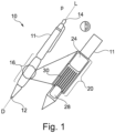
- FIG. 1 schematically illustrates a writing implement comprising a grip.
- the writing instrument 10 may be a pen, a pencil, an automatically propelling pencil, a wax crayon, a Biro (TM), a felt-tip pen, a fountain pen, a stylus for actuating an electronic device display, amongst others.
- the writing implement 10 comprises a proximal end 14 and a distal end 12 defining longitudinal bounds of a writing implement body 11.
- the distal end 12 is, during writing, brought by a user into contact with a substrate such as writing paper or a touchsensitive, or capacitive electronic device display.
- the distal end 12 of the writing implement 10 may comprise a fountain pen nib, ballpoint, felt nib, pencil lead, and the like.
- the proximal end 14 of the writing implement comprises, for example, a cap or a button for propelling a Biro nib or pencil lead into, and out of, the distal end 12.
- the writing implement 10 comprises a grip 16.
- the grip is, in examples, permanently attached to the body 11 of writing implement 10, or the grip 16 can be removably attached to the body 11 of writing implement 10 by sliding the grip 16 over the body 11 of writing implement 10 from either the proximal end 14 or the distal end 12 of the writing implement.
- the grip 16 is retained in place on the body 11 of the writing implement 10 by a friction fit.
- the grip 16 is retained in place on the body 11 of the writing implement 10 by an adhesive.
- the grip 16 is configured to release an aroma upon evaporation of the volatile liquid from the fragrance diffusion member.
- the grip controllably releases an aroma based on the degree of actuation force applied to an actuator, such as a user actuator 24.
- the grip 16 partially or fully encloses a substrate 20.
- substrate 20 contains and/or supports the liquid reservoir 22, user actuator 24, liquid transfer member 26, and fragrance diffusion member 28.
- substrate 20 is fabricated from materials suitable for defining microfluidic or macrofluidic channels for liquid transfer of the volatile liquid in the liquid reservoir 22 to the fragrance diffusion member 28.
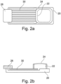
- Figure 2a schematically illustrates a side view of a first example of an aroma diffuser.
- Figure 2b schematically illustrates a plan view of the first example of the aroma diffuser.
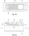
- Figure 3a schematically illustrates a plan view of the aroma diffuser of the first example when integrated into a grip for a writing implement.
- Figure 3b schematically illustrates a side view of the aroma diffuser of the first example when integrated into a grip for a writing implement.
- the grip 16 provides controlled release of an aroma carried by a volatile liquid comprised within the grip 16 according to a system to be described.
- a volatile liquid is contained within the liquid reservoir 22.
- the resulting aroma enables a user to distinguish a scent defined by the type of volatile liquid contained within the liquid reservoir 22.
- the volatile liquid comprises at least one Volatile Organic Compound (VOC)
- a grip 16 for use with a writing implement 10.
- the grip comprises a liquid reservoir 22 comprising a volatile liquid, a user actuator 24 configured to pressurize the volatile liquid in the liquid reservoir based on a force applied by a user of the grip, a liquid transfer member 26 comprising at least one channel 30 configured to provide a liquid transfer path out of the liquid reservoir, and a fragrance diffusion member 28 in fluidic communication with the at least one channel.
- an amount of volatile liquid is delivered to the fragrance diffusion member via the at least one channel in response to the user applying a force to the user actuator.
- the grip 16 is configured to release an aroma upon evaporation of the volatile liquid from the fragrance diffusion member 28.
- liquid reservoir 22 is located partially, or fully, coincident with an axis of movement of the button.
- a substrate 20 providing support for the functional elements of the fragrance diffuser is illustrated.
- Figures 2a and 2b do not illustrate the grip 16.
- substrate 20 is manufactured as a subassembly of the grip 16, and subsequently integrated into the grip 16.
- substrate 20 may be integrally formed with the grip, for example through injection moulding or 3D printing when manufacturing the grip 16.
- the substrate 20 is formed from an elastomer enabling the formation of valves for liquid control.
- the substrate is formed from the elastomer General Electric Silicones RTV 615.
- the liquid reservoir 22 is a bladder containing at least a portion of the volatile liquid, wherein the bladder is compressible during use of the grip by a user, and the user actuator is any portion of the surface of the bladder.
- the liquid reservoir 22, at least one channel 30, and the fragrance diffusion member 28 are in fluidic communication with each other.
- a user actuator 24 is coincident to the liquid reservoir 22.
- the liquid reservoir comprises, in an example, a resilient actuation surface in the form of a bubble or bladder pressurised by a volatile liquid stored in the liquid reservoir 22.
- the resilient actuation surface of the liquid reservoir 22 also functions as the user actuator 24.
- the grip 16 may be provided with a hole enabling the resilient actuation surface of the liquid reservoir 22
- a separate resilient button (for example, formed in the grip 16) that is configured, in use, to actuate the resilient actuation surface of the liquid reservoir 22 is provided.
- the grip 16 may comprise a resilient material, and the liquid reservoir 22 is formed integrally in the grip 16. Pressure exerted on the grip 16 in normal use of an associated writing implement will, therefore, be transferred through the resilient material of the grip 16 to a liquid reservoir 22 formed integrally in the grip 16, in turn pressurising a volatile liquid stored in the liquid reservoir 22.
- at least one channel 30 provides a fluidic or microfluidic connection away from the integrally formed liquid reservoir 22 and towards a fragrance diffusion member 28.
- the liquid transfer member 26 comprises at least one channel 30 (in examples, one channel 30 or a plurality of channels 30) provide a fluidic connection between the liquid reservoir 22 and the fragrance diffusion member 28.
- the at least one channel is a lumen integrally formed in the material of substrate 20.
- the substrate 20 may be formed from at least two conjoined layers, with the at least one channel formed in a first layer, and a second layer being adhesively attached so as to sealably cover the first layer.
- the substrate 20, and thus the at least one channel 30, are 3D printed.
- the substrate 20, and thus the at least one channel 30, are injection moulded.
- the substrate 20, and thus the at least one channel 30 is integrally formed with the grip 16.
- the at least one channel 30 comprised in the liquid transfer member 26 is one, or more microfluidic channels.
- the at least one channel 30 comprised in the liquid transfer member 26 is a microfluidic channel.
- a microfluidic channel is, for the purposes of this specification, considered to be a channel in which the volatile liquid experiences liquid flow characterised by a relatively low Reynolds' number when flowing through the liquid transfer member 26.
- the width of the at least one channel 30 is greater than 1 ⁇ m and less than one millimetre along substantially the entire length of the liquid transfer member 26.
- microfluidic channels in the liquid transfer member can provide fine control over the delivery of volatile liquid to the fragrance diffusion member 28.
- a valve and/or pump for controlling flow of the volatile liquid to the fragrance diffusion member 28 is not required, because the microfluidic channels comprised in the liquid transfer member present a degree of flow resistance to the volatile liquid preventing uncontrolled discharge into the fragrance diffusion member 28.
- the at least one channel 30 comprised in the liquid transfer member is a macrofluidic channel.
- the at least one channel 30 in this case has a width greater than 1 mm, or greater than 2 mm, and limited in practice by the dimensions of the grip 16.
- the fragrance diffusion member 28 is configured to absorb the volatile liquid transferred from the at least one channel 30, and to release the aroma from the grip in gaseous form.
- the fragrance diffusion member 28 comprises, in an example, a substantially porous material in fluidic communication with at least one liquid flow channel 30.
- the fragrance diffusion member 28 enables capillary action between the output of the at least one liquid flow channel 30 and an external face of the fragrance diffusion member 28 exposed to ambient air.
- the illustrated shape of the fragrance diffusion member 28 is indicative, and the fragrance diffusion member 28 may be provided in a conical, cylindrical form, or any other arbitrary form required to fit to specific type of writing implement 10 and/or grip 16 shape.
- the fragrance diffusion member 28 comprises porous polymeric fibre.
- the fragrance diffusion member 28 comprises the polyester PE (polyethylene), PP (polypropylene), PET (polyethylene terephthalate), or PBT (polybutylene terephthalate).
- the fragrance diffusion member 28 comprises a ceramic or metal foam, or a cotton wick.
- a non-diffusing portion of the fragrance diffusion member 28 is treated to prevent leakage of the volatile liquid to undesired portions of the grip 16.
- such treatment of the fragrance diffusion member 28 comprises a heat treatment applied to the non-diffusing portion of the fragrance diffusion member 28, or a nonpermeable wrap applied to the non-diffusing portion of the fragrance diffusion member 28.
- the fragrance diffusion member 28 has a density in the range of 0.30 - 0.40 g/cm 3 .
- the fragrance diffusion member 28 comprises pores with micron sizes in the range 25-125 um.
- the grip 16 comprises a mesh element 25 (formed, for example, integrally with an elastomeric or polymeric material of the grip 16).
- the mesh element 25 is aligned coincidentally with the liquid diffusion member 28, to provide a protective barrier preventing the material of the fragrance diffusion member 28 from becoming blocked or damaged.
- the fragrance diffusion member 28 is 3D printed as a porous structure and is integrally formed with the substrate 20 and/or the grip 16.
- the liquid reservoir 22 and/or the at least one channel 30 are pre-filled with a volatile liquid prior to encapsulation within the grip 16.
- a volatile liquid comprising aromas
- the liquid reservoir 22 comprises a port (not shown) to enable external refilling of the liquid reservoir 22 by a rigid lumen, for example.
- the user initially fits the grip 16 to a writing implement 10.
- the user holds the writing implement 10 in a standard way for writing.
- the user exerts a force on the user actuator 24 (or a pressure plate coupled to the user actuator) towards the longitudinal axis of the writing implement and/or grip 16.
- This can be achieved during normal writing operation, or as a deliberate user choice for example.
- the pressure on the volatile liquid stored in the liquid reservoir 22 therefore increases, causing flow of the volatile liquid through at least one channel 30 of the liquid transfer member 26.
- a proportion of volatile liquid is wicked through the fragrance diffusion member 28, and evaporates as a fragrance.
- the bladder-portion of the liquid reservoir 22 gradually deflates, and becomes concave, as the volatile liquid empties from the liquid reservoir 22. Accordingly, in this example, a positive displacement pumping action is provided by the bladder portion of the liquid reservoir 22, and valves regulating the egress of liquid from the liquid transfer member 26 into the fragrance diffusion member 28 are not required, because capillary resistance provided by the at least one channel 30 of the liquid transfer member 26 serves to confine the volatile liquid within the liquid transfer member 26 until a further positive displacement action on the user actuator 24 of the liquid reservoir 22.
- Figure 4 schematically illustrates a side view of another embodiment of an aroma diffuser.
- each channel of the liquid transfer member 26 with the aroma diffusion member 28 is provided with one or more valves 31.
- the valves seal the channels of the liquid transfer member 26 from the aroma diffusion member 28.
- the valves Upon application of positive pressure to the volatile liquid contained in the liquid transfer member 26, the valves enable the passage of volatile liquid into the aroma diffusion member 28.
- the one or more valves 31 re-seal themselves.
- the liquid reservoir 22 and/or the liquid transfer member 26 are partially, or fully enclosed in a substantially non-deformable substrate 20, and the user actuator 24 is a button 40 disposed on a portion of, or adjacent to, the non-deformable substrate 20.
- the grip further comprises at least one pump 32 configured to pump the volatile liquid from the liquid reservoir 22 to the fragrance diffusion member 28.
- the grip 16 is provided with a pump 32.
- the pump is configured to apply positive pressure to the volatile liquid based on user actuation via the button 40.
- the pump comprises a void 34, a hollow button 40, and a plunger 33 configured to move unidirectionally into the liquid reservoir 22 thus forming a positive displacement pump analogous to a syringe driver.
- the hollow button 40 is configured to move towards the longitudinal axis L of the grip 16.
- the hollow button 40 is, in an example, sprung to enable it to recoil when a user removes the finger from the button 40.
- a liquid reservoir 22 contains a volatile liquid.
- the liquid reservoir 22 comprises rigid walls (comparable for example to a syringe), to provide a sealed guide for the plunger 33.
- the liquid reservoir 22 is in liquid communication with at least one channel 30 of a liquid transfer member 26.
- the at least one channel 30 may be either a microfluidic or a macrofluidic channel, in common with the definition given previously.
- a user presses the hollow button 40 down whilst covering the air hole 38.
- the volume of the void 34 is, thereby, reduced, thus increasing compression of the air remaining in the void 34.
- This causes the plunger 33 to travel along the liquid reservoir 22 by an increment of distance, thus inducing positive pressure in the volatile liquid and forcing a portion of volatile liquid through the at least one channel 30 of the liquid transfer member 26, and into the fragrance diffusion member 28.
- the increment of distance that the plunger 33 moves is proportional to the volume of the liquid displaced when the button 40 is pressed.
- At least one valve may be provided at the interface between the at least one channel and the fragrance diffusion member 28.
- the user relaxes the force on the button 40 and removes their finger from the air hole 38, thus enabling the button to recoil (for example, using a spring).
- Repeated actuations of the button 40 lead to additional displacements of the plunger 33 until the liquid reservoir 22 is depleted of volatile liquid.
- a limiting member 36 is, for example, provided to ensure that the plunger 33 is not displaced into the void 34.
- the positive displacement pump in combination with the user actuator (button) in the embodiment illustrated in Figure 4 enables reliable control of the dosage per actuation of the user actuator.
- the air hole 38 is replaced with a membrane valve.
- a further example of a pump may be a 3D printable microvalve comprising three Quake valves in series, enabling a peristaltic pumping action to be provided. Therefore, liquid can be transferred from the liquid reservoir to the fragrance diffusion element 28 using at least three Quake valves in series.
- the liquid reservoir 22 further comprises a refill port, to enable replenishment of the volatile liquid.
- a lumen entry valve is provided at the side of the liquid reservoir 22 nearest to the liquid transfer member, so that refilled volatile liquid causes the plunger 33 to be restored to its starting position.
- the grip further comprises at least one valve 31 disposed between the at least one channel 30 and the fragrance diffusion member 28, wherein the at least one valve is configured to control the flow of volatile liquid between the at least one channel and the fragrance diffusion member.
- the valve is disposed between the liquid reservoir 22 and the at least one channel.
- the at least one valve 31 is a Quake valve, a flap valve, a membrane valve, a cusp valve, or a ball microvalve.
- Figure 5 schematically illustrates a cross-section view of a first example of a microfluidic valve.
- a valve confinement 42 is formed from a portion of the grip 16 or substrate 20.
- the volatile liquid enters the valve via valve inlet 43 and exits the valve via valve outlet 44.
- the first example of a microfluidic valve comprises a valve void 45 comprising a plurality of valve cusps 46a, 46b.
- the plurality of valve cusps 46a, 46b are closed when the liquid pressure at the valve inlet 43 and the valve outlet 44 are substantially comparable, or when the liquid pressure at the valve outlet 44 exceeds the liquid pressure at the valve inlet 43.
- valve cusps 46a, 46b Upon the exertion of positive pressure on the valve cusps 46a, 46b by a liquid at the valve inlet 43, the valve cusps 46a, 46b burst open and permit the passage of volatile liquid to the valve outlet (and subsequently to the fragrance diffusion member 28). Upon relaxation of the positive pressure on the valve cusps 46a, 46b, the valve cusps 46a, 46b close and seal the channels 30 of the liquid transfer member 26.
- FIG. 6 schematically illustrates a cross-sectional view of a second example of a microfluidic valve (a flap valve).
- a valve confinement 42 is formed from a portion of the grip 16 or substrate 20.
- a valve void 45 encloses a valve tongue 48.
- valves that can be used to seal the interface between the liquid transfer member 26 and the fragrance diffusion member 28.
- a Quake valve may be used.
- a Quake valve uses a separately pressurised control channel to constrict or relax an obstruction in a portion of microfluidic channel.
- An aspect of using a valve to seal the interface between the liquid transfer member 26 and the fragrance diffusion member 28 is to prevent unintentional discharges, or evaporation, of the volatile liquid from the liquid transfer member 26.
- the liquid transfer member 26 further comprises an actuation channel configured to be actuatable by the user actuator.
- the actuation channel is in fluidic communication with at least one control channel of the at least one valve 31.
- the actuation channel is not in fluidic communication with the liquid reservoir 22.
- a compressible elastomeric grip 16 comprises two compressible bladders that are fluidically independent.
- the first bladder functions as the liquid reservoir 22 and stores a volatile liquid.
- the second bladder (not illustrated) contains another liquid, or a gas, capable of controlling a control channel of one or more valves.
- the compressible elastomeric grip 16 is manipulated or squeezed by a user, the pressure in both bladders increases in unison.
- the liquid or gas from the second bladder actuates the control channel of at least one valve 31, enabling the volatile liquid to leave the channels of the liquid transfer member 26 and to enter the fragrance diffusion member 28.
- the controllability of the at least one valve 31 is not affected as the amount of volatile liquid depletes from the first bladder (liquid reservoir 22), thus enabling finer control of the fragrance release even at low fill levels of the liquid reservoir 22.
- a writing implement 10 comprising a writing implement body 11 and a permanent or removable grip 16 according to the first aspect, or its embodiments.
- the writing instrument 10 may be a pen, a pencil, an automatically propelling pencil, a wax crayon, a Biro (TM), a felt-tip pen, a fountain pen, a stylus for actuating an electronic device display, amongst others.
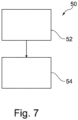
- Figure 7 schematically illustrates a method according to the third aspect.
- a method 50 of manufacturing a grip 16 for use with a writing implement comprising:
- a kit of parts comprising a first grip 16 according to the first aspect, or its embodiments, wherein the liquid reservoir 22 of the first grip 16 comprises a first type of volatile liquid.
- a kit of parts comprising a second grip according to the first aspect, or its embodiments, wherein the liquid reservoir of the second grip comprises a second type of volatile liquid; and wherein the first grip and the second grip are hermetically packaged within a shared packaging envelope.
- machine-readable program instructions capable of causing a 3D printing apparatus to manufacture the grip according to the first aspect, or its embodiments.
- references throughout the preceding specification to "one embodiment”, “an embodiment”, “one example” or “an example”, “one aspect” or “an aspect” means that a particular feature, structure, or characteristic described in connection with the embodiment or example is included in at least one embodiment of the present disclosure.
- appearances of the phrases “in one embodiment”, “in an embodiment”, “one example” or “an example”, “one aspect” or “an aspect” in various places throughout this specification are not necessarily all referring to the same embodiment or example.
Landscapes
- Pens And Brushes (AREA)
- Coating Apparatus (AREA)
Abstract
Description
- The embodiments described concern a grip for use with a writing implement, a writing implement comprising the grip, a kit of parts, and a method of assembly.
- A scented writing instrument emits an aroma, such as a coffee or perfume aroma. Scented writing instruments can be used for educational purposes, where an attractively scented pen can attract the interest of a child learning to write. Furthermore, scented writing instruments with a range of different scents enable the blind, or partially sighted, to distinguish between different pen types. Scented writing instruments have applications in aromatherapy, where scents enable a user to relax, or to instigate memories, or to stimulate creativity (dependent on the aromatherapy scent applied).
- Conventional scented writing instruments typically comprise a body element which has the liquid scent impregnated into the body element, or permanently exposed to the atmosphere via a micro grille or hole. Scented writing instruments may, therefore, be further improved.
- According to a first aspect, there is provided a grip for use with a writing implement. The grip comprises a liquid reservoir comprising a volatile liquid, a user actuator configured to pressurize the volatile liquid in the liquid reservoir based on a force applied by a user of the grip, and a liquid transfer member comprising at least one channel configured to provide a liquid transfer path out of the liquid reservoir. The grip further comprises a fragrance diffusion member in fluidic communication with the at least one channel. In use, an amount of volatile liquid is delivered to the fragrance diffusion member via the at least one channel in response to the user applying a force to the user actuator, and the grip is configured to release an aroma upon evaporation of the volatile liquid from the fragrance diffusion member.
- The release of an aroma from the grip, where the aroma has evaporated from the volatile liquid is, therefore, controllable. This contrasts with existing approaches, where the scent is emitted permanently, until all the volatile liquid has evaporated. For example, the scent is emitted only when the pen is used for writing, because the pressure exerted on the grip by a user when performing a writing operation also causes an emission of a proportion of the volatile liquid stored in the liquid reservoir. Therefore, the lifetime of the aroma emission function is improved. Furthermore, by positioning the user actuator on a part of the grip that is not actuated in usual use of the grip, the user can control the emission of aroma independently of when the grip is used.
- The grips disclosed herein are also compatible with accepted packaging and distribution practices. When a grip, or a writing implement comprising the grip, is packaged, or held in a user's pencil case, it does not emit aroma, which could otherwise become distracting in storage cupboards or warehouses. The need for providing a hermetically sealed package is removed, thus simplifying and reducing cost and environmental impact of the packaging needed. If a plurality of grips are distributed in the same package, the cross-contamination of aromas (which may result in an unpleasant smell) from one grip to another is avoided. The need to provide a complicated internal seal inside the packaging between at least two pens having mutually different scents is removed.
- The grip may be sold integrated with a writing implement, or as a retrofit option, enabling the grip to be used with a wide range of existing writing implements according to the user's choice. The integrated liquid reservoir, liquid channel, liquid transfer member, and fragrance diffusion member may be amenable to partial, or full, 3D printing. Therefore, the controlled release, and evaporation, of a volatile liquid in a fragrance emitting grip is enabled.
- According to a second aspect, there is provided a writing implement comprising a writing implement body, and a permanent or removable grip according to the first aspect.
- According to a third aspect, there is provided a method comprising assembling together at least (i) a liquid reservoir, (ii) a liquid transfer member comprising at least one channel configured to provide a liquid transfer path out of the liquid reservoir; and (iii) a fragrance diffusion member in fluidic communication with the at least one channel to provide a grip according to the first aspect or its embodiments, and filling the liquid reservoir with a volatile liquid.
- According to a fourth aspect, there is provided a kit of parts, comprising a first grip according to the first aspect or its embodiments, wherein the liquid reservoir of the first grip comprises a first type of volatile liquid.
- According to a fifth aspect, there is provided a grip according to the first aspect, or its embodiments. The liquid reservoir of the second grip comprises a second type of volatile liquid. The first grip and the second grip are hermetically packaged within a shared packaging envelope.
- According to a sixth aspect, there are provided machine-readable program instructions capable of causing a 3D printing apparatus to manufacture the grip according to the first aspect, or its embodiments.
- Other characteristics will be apparent from the accompanying drawings, which form a part of this disclosure. The drawings are intended to further explain the present disclosure and to enable a person skilled in the art to practice it. However, the drawings are intended as nonlimiting examples. Common reference numerals on different figures indicate like or similar features.
- Figure 1
- schematically illustrates a writing implement comprising a grip.
- Figure 2a
- schematically illustrates a cross-sectional plan view of a first example of an aroma diffuser.
- Figure 2b
- schematically illustrates a cross sectional side view of the first example of the aroma diffuser.
- Figure 3a
- schematically illustrates a plan view of the aroma diffuser of the first example when integrated into a grip for a writing implement.
- Figure 3b
- schematically illustrates a cross-sectional side view of the aroma diffuser of the first example when integrated into a grip for a writing implement.
- Figure 4
- schematically illustrates a side view of a second example of an aroma diffuser.
- Figure 5
- schematically illustrates a cross-section view of a first example of a microfluidic valve.
- Figure 6
- schematically illustrates a cross-sectional view of a second example of a microfluidic valve.
- Figure 7
- schematically illustrates a method according to the third aspect.
-
Figure 1 schematically illustrates a writing implement comprising a grip. Thewriting instrument 10 may be a pen, a pencil, an automatically propelling pencil, a wax crayon, a Biro (TM), a felt-tip pen, a fountain pen, a stylus for actuating an electronic device display, amongst others. In general, thewriting implement 10 comprises aproximal end 14 and adistal end 12 defining longitudinal bounds of a writing implementbody 11. Thedistal end 12 is, during writing, brought by a user into contact with a substrate such as writing paper or a touchsensitive, or capacitive electronic device display. As such, thedistal end 12 of the writing implement 10 may comprise a fountain pen nib, ballpoint, felt nib, pencil lead, and the like. Theproximal end 14 of the writing implement comprises, for example, a cap or a button for propelling a Biro nib or pencil lead into, and out of, thedistal end 12. - The
writing implement 10 comprises agrip 16. The grip is, in examples, permanently attached to thebody 11 of writing implement 10, or thegrip 16 can be removably attached to thebody 11 of writing implement 10 by sliding thegrip 16 over thebody 11 of writing implement 10 from either theproximal end 14 or thedistal end 12 of the writing implement. For example, thegrip 16 is retained in place on thebody 11 of the writing implement 10 by a friction fit. In examples, thegrip 16 is retained in place on thebody 11 of the writing implement 10 by an adhesive. Thegrip 16 is configured to release an aroma upon evaporation of the volatile liquid from the fragrance diffusion member. In an example, the grip controllably releases an aroma based on the degree of actuation force applied to an actuator, such as auser actuator 24. - The
grip 16 partially or fully encloses asubstrate 20. In an example,substrate 20 contains and/or supports theliquid reservoir 22,user actuator 24,liquid transfer member 26, andfragrance diffusion member 28. In the illustrated example,substrate 20 is fabricated from materials suitable for defining microfluidic or macrofluidic channels for liquid transfer of the volatile liquid in theliquid reservoir 22 to thefragrance diffusion member 28. -
Figure 2a schematically illustrates a side view of a first example of an aroma diffuser. -
Figure 2b schematically illustrates a plan view of the first example of the aroma diffuser. -
Figure 3a schematically illustrates a plan view of the aroma diffuser of the first example when integrated into a grip for a writing implement. -
Figure 3b schematically illustrates a side view of the aroma diffuser of the first example when integrated into a grip for a writing implement. - The
grip 16 provides controlled release of an aroma carried by a volatile liquid comprised within thegrip 16 according to a system to be described. In general, a volatile liquid is contained within theliquid reservoir 22. Upon evaporation from afragrance diffusion member 28, the resulting aroma enables a user to distinguish a scent defined by the type of volatile liquid contained within theliquid reservoir 22. In an example, the volatile liquid comprises at least one Volatile Organic Compound (VOC) - According to a first aspect, there is provided a
grip 16 for use with a writing implement 10. The grip comprises aliquid reservoir 22 comprising a volatile liquid, auser actuator 24 configured to pressurize the volatile liquid in the liquid reservoir based on a force applied by a user of the grip, aliquid transfer member 26 comprising at least onechannel 30 configured to provide a liquid transfer path out of the liquid reservoir, and afragrance diffusion member 28 in fluidic communication with the at least one channel. - In use, an amount of volatile liquid is delivered to the fragrance diffusion member via the at least one channel in response to the user applying a force to the user actuator. The
grip 16 is configured to release an aroma upon evaporation of the volatile liquid from thefragrance diffusion member 28. - According to an embodiment the
liquid reservoir 22 is located partially, or fully, coincident with an axis of movement of the button. - In the example of
Figures 2a and 2b , asubstrate 20 providing support for the functional elements of the fragrance diffuser is illustrated.Figures 2a and 2b do not illustrate thegrip 16. In an example,substrate 20 is manufactured as a subassembly of thegrip 16, and subsequently integrated into thegrip 16. In an example,substrate 20 may be integrally formed with the grip, for example through injection moulding or 3D printing when manufacturing thegrip 16. - In an example, the
substrate 20 is formed from an elastomer enabling the formation of valves for liquid control. In an example, the substrate is formed from the elastomer General Electric Silicones RTV 615. - According to an embodiment, the
liquid reservoir 22 is a bladder containing at least a portion of the volatile liquid, wherein the bladder is compressible during use of the grip by a user, and the user actuator is any portion of the surface of the bladder. - The
liquid reservoir 22, at least onechannel 30, and thefragrance diffusion member 28 are in fluidic communication with each other. Auser actuator 24 is coincident to theliquid reservoir 22. As shown inFigure 2b , the liquid reservoir comprises, in an example, a resilient actuation surface in the form of a bubble or bladder pressurised by a volatile liquid stored in theliquid reservoir 22. In this case, the resilient actuation surface of theliquid reservoir 22 also functions as theuser actuator 24. In this case, thegrip 16 may be provided with a hole enabling the resilient actuation surface of theliquid reservoir 22 In examples, a separate resilient button (for example, formed in the grip 16) that is configured, in use, to actuate the resilient actuation surface of theliquid reservoir 22 is provided. - Additionally or alternatively, the
grip 16 may comprise a resilient material, and theliquid reservoir 22 is formed integrally in thegrip 16. Pressure exerted on thegrip 16 in normal use of an associated writing implement will, therefore, be transferred through the resilient material of thegrip 16 to aliquid reservoir 22 formed integrally in thegrip 16, in turn pressurising a volatile liquid stored in theliquid reservoir 22. In this example, at least onechannel 30 provides a fluidic or microfluidic connection away from the integrally formedliquid reservoir 22 and towards afragrance diffusion member 28. - The
liquid transfer member 26 comprises at least one channel 30 (in examples, onechannel 30 or a plurality of channels 30) provide a fluidic connection between theliquid reservoir 22 and thefragrance diffusion member 28. In an example, the at least one channel is a lumen integrally formed in the material ofsubstrate 20. In examples (not illustrated), thesubstrate 20 may be formed from at least two conjoined layers, with the at least one channel formed in a first layer, and a second layer being adhesively attached so as to sealably cover the first layer. In an example, thesubstrate 20, and thus the at least onechannel 30, are 3D printed. In an example, thesubstrate 20, and thus the at least onechannel 30, are injection moulded. In an example, thesubstrate 20, and thus the at least onechannel 30 is integrally formed with thegrip 16. - According to an embodiment, the at least one
channel 30 comprised in theliquid transfer member 26 is one, or more microfluidic channels. According to an embodiment, the at least onechannel 30 comprised in theliquid transfer member 26 is a microfluidic channel. A microfluidic channel is, for the purposes of this specification, considered to be a channel in which the volatile liquid experiences liquid flow characterised by a relatively low Reynolds' number when flowing through theliquid transfer member 26. - In an example, assuming that the volatile liquid has a viscosity broadly comparable to water, the width of the at least one
channel 30 is greater than 1 µm and less than one millimetre along substantially the entire length of theliquid transfer member 26. - The use of microfluidic channels in the liquid transfer member can provide fine control over the delivery of volatile liquid to the
fragrance diffusion member 28. In an example, a valve and/or pump for controlling flow of the volatile liquid to thefragrance diffusion member 28 is not required, because the microfluidic channels comprised in the liquid transfer member present a degree of flow resistance to the volatile liquid preventing uncontrolled discharge into thefragrance diffusion member 28. - In examples, the at least one
channel 30 comprised in the liquid transfer member is a macrofluidic channel. The at least onechannel 30 in this case has a width greater than 1 mm, or greater than 2 mm, and limited in practice by the dimensions of thegrip 16. - According to an embodiment, the
fragrance diffusion member 28 is configured to absorb the volatile liquid transferred from the at least onechannel 30, and to release the aroma from the grip in gaseous form. - The
fragrance diffusion member 28 comprises, in an example, a substantially porous material in fluidic communication with at least oneliquid flow channel 30. For example, thefragrance diffusion member 28 enables capillary action between the output of the at least oneliquid flow channel 30 and an external face of thefragrance diffusion member 28 exposed to ambient air. The illustrated shape of thefragrance diffusion member 28 is indicative, and thefragrance diffusion member 28 may be provided in a conical, cylindrical form, or any other arbitrary form required to fit to specific type of writing implement 10 and/orgrip 16 shape. In an example, thefragrance diffusion member 28 comprises porous polymeric fibre. - In an example, the
fragrance diffusion member 28 comprises the polyester PE (polyethylene), PP (polypropylene), PET (polyethylene terephthalate), or PBT (polybutylene terephthalate). In an example, thefragrance diffusion member 28 comprises a ceramic or metal foam, or a cotton wick. In an example, a non-diffusing portion of thefragrance diffusion member 28 is treated to prevent leakage of the volatile liquid to undesired portions of thegrip 16. For example, such treatment of thefragrance diffusion member 28 comprises a heat treatment applied to the non-diffusing portion of thefragrance diffusion member 28, or a nonpermeable wrap applied to the non-diffusing portion of thefragrance diffusion member 28. - In an example, the
fragrance diffusion member 28 has a density in the range of 0.30 - 0.40 g/cm3. In an example, thefragrance diffusion member 28 comprises pores with micron sizes in the range 25-125 um. - In an example, the
grip 16 comprises a mesh element 25 (formed, for example, integrally with an elastomeric or polymeric material of the grip 16). Themesh element 25 is aligned coincidentally with theliquid diffusion member 28, to provide a protective barrier preventing the material of thefragrance diffusion member 28 from becoming blocked or damaged. - In an example, the
fragrance diffusion member 28 is 3D printed as a porous structure and is integrally formed with thesubstrate 20 and/or thegrip 16. - In an example, the
liquid reservoir 22 and/or the at least onechannel 30 are pre-filled with a volatile liquid prior to encapsulation within thegrip 16. A wide range of volatile liquids comprising aromas may be pre-filled. In an example, theliquid reservoir 22 comprises a port (not shown) to enable external refilling of theliquid reservoir 22 by a rigid lumen, for example. - Turning to
Figure 3b , in use, the user initially fits thegrip 16 to a writing implement 10. The user holds the writing implement 10 in a standard way for writing. Deliberately, or coincidentally, the user exerts a force on the user actuator 24 (or a pressure plate coupled to the user actuator) towards the longitudinal axis of the writing implement and/orgrip 16. This can be achieved during normal writing operation, or as a deliberate user choice for example. The pressure on the volatile liquid stored in theliquid reservoir 22 therefore increases, causing flow of the volatile liquid through at least onechannel 30 of theliquid transfer member 26. A proportion of volatile liquid is wicked through thefragrance diffusion member 28, and evaporates as a fragrance. In the system illustrated inFigures 2 and3 , the bladder-portion of theliquid reservoir 22 gradually deflates, and becomes concave, as the volatile liquid empties from theliquid reservoir 22. Accordingly, in this example, a positive displacement pumping action is provided by the bladder portion of theliquid reservoir 22, and valves regulating the egress of liquid from theliquid transfer member 26 into thefragrance diffusion member 28 are not required, because capillary resistance provided by the at least onechannel 30 of theliquid transfer member 26 serves to confine the volatile liquid within theliquid transfer member 26 until a further positive displacement action on theuser actuator 24 of theliquid reservoir 22. - Variations will now be discussed.
-
Figure 4 schematically illustrates a side view of another embodiment of an aroma diffuser. - In the grip embodiment of
Figure 4 , the interface of each channel of theliquid transfer member 26 with thearoma diffusion member 28 is provided with one ormore valves 31. The valves seal the channels of theliquid transfer member 26 from thearoma diffusion member 28. Upon application of positive pressure to the volatile liquid contained in theliquid transfer member 26, the valves enable the passage of volatile liquid into thearoma diffusion member 28. When the positive pressure is removed from the volatile liquid, the one ormore valves 31 re-seal themselves. - In embodiments, the
liquid reservoir 22 and/or theliquid transfer member 26 are partially, or fully enclosed in a substantiallynon-deformable substrate 20, and theuser actuator 24 is abutton 40 disposed on a portion of, or adjacent to, thenon-deformable substrate 20. - In embodiments, the grip further comprises at least one
pump 32 configured to pump the volatile liquid from theliquid reservoir 22 to thefragrance diffusion member 28. - According to the embodiment illustrated in
Figure 4 , thegrip 16 is provided with apump 32. The pump is configured to apply positive pressure to the volatile liquid based on user actuation via thebutton 40. The pump comprises a void 34, ahollow button 40, and aplunger 33 configured to move unidirectionally into theliquid reservoir 22 thus forming a positive displacement pump analogous to a syringe driver. Thehollow button 40 is configured to move towards the longitudinal axis L of thegrip 16. Thehollow button 40 is, in an example, sprung to enable it to recoil when a user removes the finger from thebutton 40. - A
liquid reservoir 22 contains a volatile liquid. Theliquid reservoir 22 comprises rigid walls (comparable for example to a syringe), to provide a sealed guide for theplunger 33. Theliquid reservoir 22 is in liquid communication with at least onechannel 30 of aliquid transfer member 26. In this embodiment, the at least onechannel 30 may be either a microfluidic or a macrofluidic channel, in common with the definition given previously. - In use, a user presses the
hollow button 40 down whilst covering theair hole 38. The volume of the void 34 is, thereby, reduced, thus increasing compression of the air remaining in thevoid 34. This, in turn, causes theplunger 33 to travel along theliquid reservoir 22 by an increment of distance, thus inducing positive pressure in the volatile liquid and forcing a portion of volatile liquid through the at least onechannel 30 of theliquid transfer member 26, and into thefragrance diffusion member 28. For example, the increment of distance that theplunger 33 moves is proportional to the volume of the liquid displaced when thebutton 40 is pressed. - In an example, at least one valve may be provided at the interface between the at least one channel and the
fragrance diffusion member 28. The user relaxes the force on thebutton 40 and removes their finger from theair hole 38, thus enabling the button to recoil (for example, using a spring). Repeated actuations of thebutton 40 lead to additional displacements of theplunger 33 until theliquid reservoir 22 is depleted of volatile liquid. A limitingmember 36 is, for example, provided to ensure that theplunger 33 is not displaced into the void 34. - Therefore, the positive displacement pump in combination with the user actuator (button) in the embodiment illustrated in
Figure 4 enables reliable control of the dosage per actuation of the user actuator. Other variations of the embodiment ofFigure 4 are possible. For example, theair hole 38 is replaced with a membrane valve. - A further example of a pump may be a 3D printable microvalve comprising three Quake valves in series, enabling a peristaltic pumping action to be provided. Therefore, liquid can be transferred from the liquid reservoir to the
fragrance diffusion element 28 using at least three Quake valves in series. - According to an embodiment, the
liquid reservoir 22 further comprises a refill port, to enable replenishment of the volatile liquid. - In a refillable variation of the embodiment of
Figure 4 , a lumen entry valve is provided at the side of theliquid reservoir 22 nearest to the liquid transfer member, so that refilled volatile liquid causes theplunger 33 to be restored to its starting position. - According to an embodiment, the grip further comprises at least one
valve 31 disposed between the at least onechannel 30 and thefragrance diffusion member 28, wherein the at least one valve is configured to control the flow of volatile liquid between the at least one channel and the fragrance diffusion member. - According to an embodiment, the valve is disposed between the
liquid reservoir 22 and the at least one channel. - According to an embodiment, the at least one
valve 31 is a Quake valve, a flap valve, a membrane valve, a cusp valve, or a ball microvalve. -
Figure 5 schematically illustrates a cross-section view of a first example of a microfluidic valve. For example, avalve confinement 42 is formed from a portion of thegrip 16 orsubstrate 20. The volatile liquid enters the valve viavalve inlet 43 and exits the valve viavalve outlet 44. The first example of a microfluidic valve comprises avalve void 45 comprising a plurality ofvalve cusps valve cusps valve inlet 43 and thevalve outlet 44 are substantially comparable, or when the liquid pressure at thevalve outlet 44 exceeds the liquid pressure at thevalve inlet 43. Upon the exertion of positive pressure on thevalve cusps valve inlet 43, thevalve cusps valve cusps valve cusps channels 30 of theliquid transfer member 26. -
Figure 6 schematically illustrates a cross-sectional view of a second example of a microfluidic valve (a flap valve). For example, avalve confinement 42 is formed from a portion of thegrip 16 orsubstrate 20. Avalve void 45 encloses avalve tongue 48. When the second example of the microfluidic valve experiences a positive pressure applied via thevalve inlet 43, thevalve tongue 48 is forced open (as shown inFigure 6 b) ), enabling the volatile liquid to flow to thevalue outlet 44. When the pressure applied to the volatile liquid is removed, the valve tongue seals the valve. - The foregoing description provides examples of valves that can be used to seal the interface between the
liquid transfer member 26 and thefragrance diffusion member 28. In an example, a Quake valve may be used. A Quake valve uses a separately pressurised control channel to constrict or relax an obstruction in a portion of microfluidic channel. An aspect of using a valve to seal the interface between theliquid transfer member 26 and thefragrance diffusion member 28 is to prevent unintentional discharges, or evaporation, of the volatile liquid from theliquid transfer member 26. - According to an embodiment, the
liquid transfer member 26 further comprises an actuation channel configured to be actuatable by the user actuator. The actuation channel is in fluidic communication with at least one control channel of the at least onevalve 31. The actuation channel is not in fluidic communication with theliquid reservoir 22. - For example, a compressible
elastomeric grip 16 comprises two compressible bladders that are fluidically independent. The first bladder functions as theliquid reservoir 22 and stores a volatile liquid. The second bladder (not illustrated) contains another liquid, or a gas, capable of controlling a control channel of one or more valves. When the compressibleelastomeric grip 16 is manipulated or squeezed by a user, the pressure in both bladders increases in unison. The liquid or gas from the second bladder actuates the control channel of at least onevalve 31, enabling the volatile liquid to leave the channels of theliquid transfer member 26 and to enter thefragrance diffusion member 28. Because the second bladder (actuation channel) is not in fluidic communication with theliquid reservoir 22, the controllability of the at least onevalve 31 is not affected as the amount of volatile liquid depletes from the first bladder (liquid reservoir 22), thus enabling finer control of the fragrance release even at low fill levels of theliquid reservoir 22. - According to a second aspect, there is provided a writing implement 10, comprising a writing implement
body 11 and a permanent orremovable grip 16 according to the first aspect, or its embodiments. The writinginstrument 10 may be a pen, a pencil, an automatically propelling pencil, a wax crayon, a Biro (TM), a felt-tip pen, a fountain pen, a stylus for actuating an electronic device display, amongst others. -
Figure 7 schematically illustrates a method according to the third aspect. - According to a third aspect, there is provided a
method 50 of manufacturing agrip 16 for use with a writing implement, comprising: - assembling, or 3D printing, at least (i) a
liquid reservoir 22, (ii) aliquid transfer member 26 comprising at least onechannel 30 configured to provide a liquid transfer path out of theliquid reservoir 22; and (iii) afragrance diffusion member 28 in fluidic communication with the at least onechannel 30 to provide a grip for a writing implement 10; and - filling 54 the liquid reservoir with a volatile liquid.
- According to a fourth aspect, there is provided a kit of parts, comprising a
first grip 16 according to the first aspect, or its embodiments, wherein theliquid reservoir 22 of thefirst grip 16 comprises a first type of volatile liquid. - According to a fifth aspect, there is provided a kit of parts comprising a second grip according to the first aspect, or its embodiments, wherein the liquid reservoir of the second grip comprises a second type of volatile liquid; and wherein the first grip and the second grip are hermetically packaged within a shared packaging envelope.
- According to a sixth aspect, there are provided machine-readable program instructions capable of causing a 3D printing apparatus to manufacture the grip according to the first aspect, or its embodiments.
- References throughout the preceding specification to "one embodiment", "an embodiment", "one example" or "an example", "one aspect" or "an aspect" means that a particular feature, structure, or characteristic described in connection with the embodiment or example is included in at least one embodiment of the present disclosure. Thus, appearances of the phrases "in one embodiment", "in an embodiment", "one example" or "an example", "one aspect" or "an aspect" in various places throughout this specification are not necessarily all referring to the same embodiment or example.
- Furthermore, the particular features, structures, or characteristics may be combined in any suitable combinations and / or sub-combinations in one or more embodiments or examples.
-
- 10
- Writing Implement
- 11
- Writing implement body
- 12
- Proximal end of writing implement
- 14
- Distal end of writing implement
- 16
- Grip
- 20
- substrate
- 22
- liquid reservoir
- 24
- user actuator
- 25
- mesh
- 26
- liquid transfer member
- 28
- fragrance diffusion member
- 30
- channel
- 31
- valve
- 32
- pump
- 33
- plunger
- 34
- void
- 36
- limiting member
- 38
- airhole
- 40
- button
- 42
- valve confinement
- 43
- valve inlet
- 44
- valve outlet
- 45
- valve void
- 46a, b
- valve cusps
- 48
- valve tongue
- 50
- method
- 52
- assembling or 3D printing
- 54
- filling with liquid
Claims (15)
- A grip (16) for use with a writing implement (10), wherein the grip comprises:- a liquid reservoir (22) comprising a volatile liquid;- a user actuator (24) configured to pressurize the volatile liquid in the liquid reservoir based on a force applied by a user of the grip;- a liquid transfer member (26) comprising at least one channel (30) configured to provide a liquid transfer path out of the liquid reservoir; and- a fragrance diffusion member (28) in liquid communication with the at least one channel;wherein, in use, an amount of volatile liquid is delivered to the fragrance diffusion member (28) via the at least one channel (30) in response to the user applying a force to the user actuator (24), and wherein the grip (16) is configured to release an aroma upon evaporation of the volatile liquid from the fragrance diffusion member.
- The grip (16) according to claim 1,
wherein the at least one channel (30) comprised in the liquid transfer member (26) is one, or more microfluidic channels. - The grip (16) according to claim 1 or 2, further comprising:- at least one valve (31) disposed between the at least one channel (30) and the fragrance diffusion member (28), wherein the at least one valve is configured to control the flow of volatile liquid between the at least one channel and the fragrance diffusion member.
- The grip (16) according to claim 3,
wherein the at least one valve (31) is a Quake valve, a flap valve, a membrane valve, a cusp valve, or a ball microvalve. - The grip (16) according to one of the preceding claims, further comprising:- at least one pump (32) configured to pump the volatile liquid from the liquid reservoir (22) to the fragrance diffusion member (28).
- The grip (16) according to one of the preceding claims,
wherein the fragrance diffusion member (28) is configured to absorb the volatile liquid transferred from the at least one channel (30), and to release the aroma from the grip in gaseous form. - The grip (16) according to one of claims 1 to 6,
wherein the liquid reservoir (22) is a bladder containing at least a portion of the volatile liquid, wherein the bladder is compressible during use of the grip by a user, and the user actuator is any portion of the surface of the bladder. - The grip (16) according to one of claims 1 to 6,
wherein the liquid reservoir (22) and/or the liquid transfer member (26) are partially, or fully enclosed in a substantially non-deformable substrate (20), and the user actuator (24) is a button (40) disposed on a portion of, or adjacent to, the non-deformable substrate (20). - The grip (16) according to one of claim 8,
wherein the liquid reservoir (22) is located partially, or fully, coincident with an axis of movement of the button. - The grip (16) according to one of claims 3 to 9,
wherein the liquid transfer member (26) further comprises an actuation channel configured to be actuatable by the user actuator, wherein the actuation channel is in liquid communication with at least one control channel of the at least one valve (31), and wherein the actuation channel is not in liquid communication with the liquid reservoir (22). - The grip (16) according to one of the preceding claims,
wherein the liquid reservoir (22) further comprises a refill port, to enable replenishment of the volatile liquid. - A method (50) of manufacturing a grip for use with a writing implement, comprising:- assembling, or 3D printing, (52) at least (i) a liquid reservoir, (ii) a liquid transfer member comprising at least one channel configured to provide a liquid transfer path out of the liquid reservoir; and (iii) a fragrance diffusion member in liquid communication with the at least one channel to provide a grip for a writing implement; and- filling (54) the liquid reservoir with a volatile liquid.
- A writing implement (10), comprising:- a writing implement body (11), and- a permanent or removable grip (16) according to one of claims 1 to 11.
- A kit of parts, comprising:- a first grip according to one of claims 1 to 11, wherein the liquid reservoir of the first grip comprises a first type of volatile liquid, and a writing implement.
- The kit of parts according to claim 14, further comprising:- a second grip according to one of claims 1 to 11, wherein the liquid reservoir of the second grip comprises a second type of volatile liquid;wherein the first grip and the second grip are packaged within a shared packaging envelope.
Priority Applications (4)
| Application Number | Priority Date | Filing Date | Title |
|---|---|---|---|
| EP22154263.2A EP4219187A1 (en) | 2022-01-31 | 2022-01-31 | Grip for a writing implement |
| US18/832,767 US20250100318A1 (en) | 2022-01-31 | 2023-01-24 | Grip for a writing implement |
| PCT/EP2023/051674 WO2023144139A1 (en) | 2022-01-31 | 2023-01-24 | Grip for a writing implement |
| JP2024539427A JP2025504762A (en) | 2022-01-31 | 2023-01-24 | Writing Instrument Grips |
Applications Claiming Priority (1)
| Application Number | Priority Date | Filing Date | Title |
|---|---|---|---|
| EP22154263.2A EP4219187A1 (en) | 2022-01-31 | 2022-01-31 | Grip for a writing implement |
Publications (1)
| Publication Number | Publication Date |
|---|---|
| EP4219187A1 true EP4219187A1 (en) | 2023-08-02 |
Family
ID=80119302
Family Applications (1)
| Application Number | Title | Priority Date | Filing Date |
|---|---|---|---|
| EP22154263.2A Pending EP4219187A1 (en) | 2022-01-31 | 2022-01-31 | Grip for a writing implement |
Country Status (4)
| Country | Link |
|---|---|
| US (1) | US20250100318A1 (en) |
| EP (1) | EP4219187A1 (en) |
| JP (1) | JP2025504762A (en) |
| WO (1) | WO2023144139A1 (en) |
Citations (2)
| Publication number | Priority date | Publication date | Assignee | Title |
|---|---|---|---|---|
| US3888416A (en) * | 1974-05-06 | 1975-06-10 | A Oscar Lin | Scented writing instrument |
| US4244525A (en) * | 1979-11-13 | 1981-01-13 | Manna Ronald A | Writing instrument with refillable scent dispenser |
Family Cites Families (11)
| Publication number | Priority date | Publication date | Assignee | Title |
|---|---|---|---|---|
| US4200229A (en) * | 1978-12-20 | 1980-04-29 | Donald Spector | Aroma-dispensing cartridge and holder assembly |
| US4609245A (en) * | 1984-11-21 | 1986-09-02 | Sakschek Helmut W | Dispenser and method for dispensing hunting odors |
| US6945473B2 (en) * | 2001-12-20 | 2005-09-20 | Valois S.A.S. | Fluid product dispenser |
| US6899486B2 (en) * | 2002-07-18 | 2005-05-31 | Eric L. Wetzel | Pen with a scented housing |
| US7147171B2 (en) * | 2002-12-10 | 2006-12-12 | Lumica Corporation | Diffuser for volatile material such as aromatic or chemical agent |
| US20070020033A1 (en) * | 2005-06-09 | 2007-01-25 | Daniel Walsh | Scent emitting writing instrument |
| KR101255714B1 (en) * | 2010-12-09 | 2013-04-17 | 손진모 | Writing tool with controlling function of aroma evaration |
| US20150014428A1 (en) * | 2013-07-10 | 2015-01-15 | Woodpecker Laboratories, LLC | Portable devices and methods for providing scents |
| KR101910676B1 (en) * | 2013-11-14 | 2018-10-22 | 카즈히로 가와사키 | Perfume case |
| US20150197118A1 (en) * | 2014-01-15 | 2015-07-16 | Les Wagenheim | Aroma dispersing writing instrument |
| US9956810B2 (en) * | 2015-06-19 | 2018-05-01 | Christopher W. E. Cote | Scented writing instruments and methods for making the same |
-
2022
- 2022-01-31 EP EP22154263.2A patent/EP4219187A1/en active Pending
-
2023
- 2023-01-24 WO PCT/EP2023/051674 patent/WO2023144139A1/en not_active Ceased
- 2023-01-24 JP JP2024539427A patent/JP2025504762A/en active Pending
- 2023-01-24 US US18/832,767 patent/US20250100318A1/en active Pending
Patent Citations (2)
| Publication number | Priority date | Publication date | Assignee | Title |
|---|---|---|---|---|
| US3888416A (en) * | 1974-05-06 | 1975-06-10 | A Oscar Lin | Scented writing instrument |
| US4244525A (en) * | 1979-11-13 | 1981-01-13 | Manna Ronald A | Writing instrument with refillable scent dispenser |
Also Published As
| Publication number | Publication date |
|---|---|
| JP2025504762A (en) | 2025-02-19 |
| WO2023144139A1 (en) | 2023-08-03 |
| US20250100318A1 (en) | 2025-03-27 |
Similar Documents
| Publication | Publication Date | Title |
|---|---|---|
| CN107690289B (en) | dispensing agency | |
| US7149417B2 (en) | Controllable release of a volatile substance | |
| AU2015277014B2 (en) | Microfluidic delivery system for releasing fluid compositions | |
| US4244525A (en) | Writing instrument with refillable scent dispenser | |
| EP1557289A1 (en) | Liquid-dispensing container for a marking instrument | |
| KR20100092049A (en) | Fluid delivery system | |
| CN1265975C (en) | marker pen | |
| WO1998058684A1 (en) | Controlled release of substances | |
| US5518331A (en) | Refillable ink pen | |
| JPH0624195A (en) | Writing instrument | |
| US20020192010A1 (en) | Pressure modulated free ink marker for producing variable line width | |
| US6837640B2 (en) | Applicator | |
| US20250100318A1 (en) | Grip for a writing implement | |
| EP3162586B1 (en) | Fountain pen and clean ink refill system | |
| JP2004525795A (en) | Free ink system | |
| JP3290653B2 (en) | Pen | |
| US3533708A (en) | Ball point pen for water soluble ink | |
| US6045055A (en) | Device and method for delivering fluid | |
| US5938359A (en) | Writing instrument having sanitary moistener | |
| CN1210169C (en) | Liquid ink writing article with shape-memory valve | |
| CN101720282A (en) | Implement for writing, marking and/or painting | |
| JP2014240154A (en) | Ink self-feeding type seal | |
| EP1837200A2 (en) | Ink writing device and method for controlling the flow of ink at the tip of the nib | |
| US20060131343A1 (en) | Fluid dispensing system | |
| US20250360283A1 (en) | Aromatherapy device |
Legal Events
| Date | Code | Title | Description |
|---|---|---|---|
| PUAI | Public reference made under article 153(3) epc to a published international application that has entered the european phase |
Free format text: ORIGINAL CODE: 0009012 |
|
| STAA | Information on the status of an ep patent application or granted ep patent |
Free format text: STATUS: THE APPLICATION HAS BEEN PUBLISHED |
|
| AK | Designated contracting states |
Kind code of ref document: A1 Designated state(s): AL AT BE BG CH CY CZ DE DK EE ES FI FR GB GR HR HU IE IS IT LI LT LU LV MC MK MT NL NO PL PT RO RS SE SI SK SM TR |
|
| STAA | Information on the status of an ep patent application or granted ep patent |
Free format text: STATUS: REQUEST FOR EXAMINATION WAS MADE |
|
| 17P | Request for examination filed |
Effective date: 20231127 |
|
| RBV | Designated contracting states (corrected) |
Designated state(s): AL AT BE BG CH CY CZ DE DK EE ES FI FR GB GR HR HU IE IS IT LI LT LU LV MC MK MT NL NO PL PT RO RS SE SI SK SM TR |