EP4218908A1 - Temperature measurement in arrays for delivering ttfields - Google Patents
Temperature measurement in arrays for delivering ttfields Download PDFInfo
- Publication number
- EP4218908A1 EP4218908A1 EP23168148.7A EP23168148A EP4218908A1 EP 4218908 A1 EP4218908 A1 EP 4218908A1 EP 23168148 A EP23168148 A EP 23168148A EP 4218908 A1 EP4218908 A1 EP 4218908A1
- Authority
- EP
- European Patent Office
- Prior art keywords
- analog
- hub
- controller
- electrode elements
- cable
- Prior art date
- Legal status (The legal status is an assumption and is not a legal conclusion. Google has not performed a legal analysis and makes no representation as to the accuracy of the status listed.)
- Pending
Links
- 238000003491 array Methods 0.000 title claims abstract description 46
- 238000009529 body temperature measurement Methods 0.000 title abstract description 10
- 239000003990 capacitor Substances 0.000 claims abstract description 3
- 239000004020 conductor Substances 0.000 claims description 89
- 239000000758 substrate Substances 0.000 claims description 23
- 238000000034 method Methods 0.000 abstract description 8
- 238000013459 approach Methods 0.000 abstract description 7
- 206010028980 Neoplasm Diseases 0.000 abstract description 5
- 230000005684 electric field Effects 0.000 abstract description 5
- 238000002560 therapeutic procedure Methods 0.000 abstract description 2
- 238000004891 communication Methods 0.000 description 13
- 230000005540 biological transmission Effects 0.000 description 8
- 238000010586 diagram Methods 0.000 description 6
- 238000005259 measurement Methods 0.000 description 4
- 230000001360 synchronised effect Effects 0.000 description 4
- 230000005855 radiation Effects 0.000 description 3
- 230000001954 sterilising effect Effects 0.000 description 3
- 238000004659 sterilization and disinfection Methods 0.000 description 3
- 241000218691 Cupressaceae Species 0.000 description 2
- 239000002390 adhesive tape Substances 0.000 description 2
- 230000000694 effects Effects 0.000 description 2
- 238000012986 modification Methods 0.000 description 2
- 230000004048 modification Effects 0.000 description 2
- 230000004075 alteration Effects 0.000 description 1
- 230000000712 assembly Effects 0.000 description 1
- 238000000429 assembly Methods 0.000 description 1
- 230000002457 bidirectional effect Effects 0.000 description 1
- 239000000919 ceramic Substances 0.000 description 1
- 230000002354 daily effect Effects 0.000 description 1
- 238000013461 design Methods 0.000 description 1
- 238000005516 engineering process Methods 0.000 description 1
- 230000003203 everyday effect Effects 0.000 description 1
- 210000003128 head Anatomy 0.000 description 1
- 230000002452 interceptive effect Effects 0.000 description 1
- 238000012827 research and development Methods 0.000 description 1
- 210000004761 scalp Anatomy 0.000 description 1
Images


Classifications
-
- A—HUMAN NECESSITIES
- A61—MEDICAL OR VETERINARY SCIENCE; HYGIENE
- A61N—ELECTROTHERAPY; MAGNETOTHERAPY; RADIATION THERAPY; ULTRASOUND THERAPY
- A61N1/00—Electrotherapy; Circuits therefor
- A61N1/18—Applying electric currents by contact electrodes
- A61N1/32—Applying electric currents by contact electrodes alternating or intermittent currents
- A61N1/36—Applying electric currents by contact electrodes alternating or intermittent currents for stimulation
- A61N1/36002—Cancer treatment, e.g. tumour
-
- A—HUMAN NECESSITIES
- A61—MEDICAL OR VETERINARY SCIENCE; HYGIENE
- A61N—ELECTROTHERAPY; MAGNETOTHERAPY; RADIATION THERAPY; ULTRASOUND THERAPY
- A61N1/00—Electrotherapy; Circuits therefor
- A61N1/40—Applying electric fields by inductive or capacitive coupling ; Applying radio-frequency signals
-
- A—HUMAN NECESSITIES
- A61—MEDICAL OR VETERINARY SCIENCE; HYGIENE
- A61B—DIAGNOSIS; SURGERY; IDENTIFICATION
- A61B18/00—Surgical instruments, devices or methods for transferring non-mechanical forms of energy to or from the body
- A61B18/04—Surgical instruments, devices or methods for transferring non-mechanical forms of energy to or from the body by heating
- A61B18/12—Surgical instruments, devices or methods for transferring non-mechanical forms of energy to or from the body by heating by passing a current through the tissue to be heated, e.g. high-frequency current
- A61B18/14—Probes or electrodes therefor
-
- A—HUMAN NECESSITIES
- A61—MEDICAL OR VETERINARY SCIENCE; HYGIENE
- A61K—PREPARATIONS FOR MEDICAL, DENTAL OR TOILETRY PURPOSES
- A61K41/00—Medicinal preparations obtained by treating materials with wave energy or particle radiation ; Therapies using these preparations
- A61K41/0052—Thermotherapy; Hyperthermia; Magnetic induction; Induction heating therapy
-
- A—HUMAN NECESSITIES
- A61—MEDICAL OR VETERINARY SCIENCE; HYGIENE
- A61N—ELECTROTHERAPY; MAGNETOTHERAPY; RADIATION THERAPY; ULTRASOUND THERAPY
- A61N1/00—Electrotherapy; Circuits therefor
- A61N1/02—Details
- A61N1/04—Electrodes
- A61N1/0404—Electrodes for external use
- A61N1/0408—Use-related aspects
-
- A—HUMAN NECESSITIES
- A61—MEDICAL OR VETERINARY SCIENCE; HYGIENE
- A61N—ELECTROTHERAPY; MAGNETOTHERAPY; RADIATION THERAPY; ULTRASOUND THERAPY
- A61N1/00—Electrotherapy; Circuits therefor
- A61N1/02—Details
- A61N1/04—Electrodes
- A61N1/0404—Electrodes for external use
- A61N1/0472—Structure-related aspects
- A61N1/0476—Array electrodes (including any electrode arrangement with more than one electrode for at least one of the polarities)
-
- A—HUMAN NECESSITIES
- A61—MEDICAL OR VETERINARY SCIENCE; HYGIENE
- A61N—ELECTROTHERAPY; MAGNETOTHERAPY; RADIATION THERAPY; ULTRASOUND THERAPY
- A61N1/00—Electrotherapy; Circuits therefor
- A61N1/02—Details
- A61N1/04—Electrodes
- A61N1/0404—Electrodes for external use
- A61N1/0472—Structure-related aspects
- A61N1/0492—Patch electrodes
-
- A—HUMAN NECESSITIES
- A61—MEDICAL OR VETERINARY SCIENCE; HYGIENE
- A61N—ELECTROTHERAPY; MAGNETOTHERAPY; RADIATION THERAPY; ULTRASOUND THERAPY
- A61N1/00—Electrotherapy; Circuits therefor
- A61N1/02—Details
- A61N1/04—Electrodes
- A61N1/06—Electrodes for high-frequency therapy
-
- A—HUMAN NECESSITIES
- A61—MEDICAL OR VETERINARY SCIENCE; HYGIENE
- A61N—ELECTROTHERAPY; MAGNETOTHERAPY; RADIATION THERAPY; ULTRASOUND THERAPY
- A61N1/00—Electrotherapy; Circuits therefor
- A61N1/18—Applying electric currents by contact electrodes
- A61N1/32—Applying electric currents by contact electrodes alternating or intermittent currents
- A61N1/36—Applying electric currents by contact electrodes alternating or intermittent currents for stimulation
- A61N1/36014—External stimulators, e.g. with patch electrodes
- A61N1/3603—Control systems
- A61N1/36031—Control systems using physiological parameters for adjustment
-
- A—HUMAN NECESSITIES
- A61—MEDICAL OR VETERINARY SCIENCE; HYGIENE
- A61B—DIAGNOSIS; SURGERY; IDENTIFICATION
- A61B18/00—Surgical instruments, devices or methods for transferring non-mechanical forms of energy to or from the body
- A61B2018/00636—Sensing and controlling the application of energy
- A61B2018/00642—Sensing and controlling the application of energy with feedback, i.e. closed loop control
- A61B2018/00648—Sensing and controlling the application of energy with feedback, i.e. closed loop control using more than one sensed parameter
-
- A—HUMAN NECESSITIES
- A61—MEDICAL OR VETERINARY SCIENCE; HYGIENE
- A61B—DIAGNOSIS; SURGERY; IDENTIFICATION
- A61B18/00—Surgical instruments, devices or methods for transferring non-mechanical forms of energy to or from the body
- A61B2018/00636—Sensing and controlling the application of energy
- A61B2018/00773—Sensed parameters
- A61B2018/00791—Temperature
-
- A—HUMAN NECESSITIES
- A61—MEDICAL OR VETERINARY SCIENCE; HYGIENE
- A61N—ELECTROTHERAPY; MAGNETOTHERAPY; RADIATION THERAPY; ULTRASOUND THERAPY
- A61N1/00—Electrotherapy; Circuits therefor
- A61N1/18—Applying electric currents by contact electrodes
Landscapes
- Health & Medical Sciences (AREA)
- Life Sciences & Earth Sciences (AREA)
- Engineering & Computer Science (AREA)
- General Health & Medical Sciences (AREA)
- Animal Behavior & Ethology (AREA)
- Public Health (AREA)
- Veterinary Medicine (AREA)
- Biomedical Technology (AREA)
- Nuclear Medicine, Radiotherapy & Molecular Imaging (AREA)
- Radiology & Medical Imaging (AREA)
- Heart & Thoracic Surgery (AREA)
- Biophysics (AREA)
- Surgery (AREA)
- Oncology (AREA)
- Hospice & Palliative Care (AREA)
- Otolaryngology (AREA)
- Plasma & Fusion (AREA)
- Physics & Mathematics (AREA)
- Medical Informatics (AREA)
- Molecular Biology (AREA)
- Chemical & Material Sciences (AREA)
- Medicinal Chemistry (AREA)
- Pharmacology & Pharmacy (AREA)
- Epidemiology (AREA)
- Physiology (AREA)
- Measuring And Recording Apparatus For Diagnosis (AREA)
- Arrangements For Transmission Of Measured Signals (AREA)
- Electrotherapy Devices (AREA)
- Measuring Temperature Or Quantity Of Heat (AREA)
- Chemical Kinetics & Catalysis (AREA)
- General Chemical & Material Sciences (AREA)
- Thermotherapy And Cooling Therapy Devices (AREA)
Abstract
Description
- TTFields therapy is a proven approach for treating tumors. In the prior art Optune® system for delivering TTFields, the TTFields are delivered to patients via four transducer arrays placed on the patient's skin in close proximity to a tumor. The transducer arrays are arranged in two pairs, and each transducer array is connected via a multi-wire cable to a field generator. The field generator (a) sends an AC current through one pair of arrays during a first period of time; then (b) sends an AC current through the other pair of arrays during a second period of time; then repeats steps (a) and (b) for the duration of the treatment.
- Each transducer array is configured as a set of capacitively coupled electrode elements (about 2 cm in diameter) that are interconnected via flex wires. Each electrode element includes a ceramic disk that is sandwiched between a layer of an electrically conductive medical gel and an adhesive tape. When placing the arrays on the patient, the medical gel adheres to the contours of the patient's skin and ensures good electric contact of the device with the body. The adhesive tape holds the entire array in place on the patient as the patient goes about their daily activities.
- The amplitude of the alternating current that is delivered via the transducer arrays is controlled so that skin temperature (as measured on the skin below the transducer arrays) does not exceed a safety threshold of 41 degrees Celsius. The temperature measurements on the patient's skin are obtained using thermistors placed beneath some of the disks of the transducer arrays. In the existing Optune® system, each array includes 8 thermistors, with one thermistor positioned beneath a respective disk in the array. (Note that most arrays include more than 8 disks, in which case the temperature measurements are only performed beneath a sub-set of the disks within the array).
- The thermistors in each of the four arrays are connected via long wires to an electronic device called the "cable box" where the temperature from all 32 thermistors (4 arrays × 8 thermistors per array) is measured and analog-to-digital converted into digital values for each thermistor. These measurements are then transmitted from the cable box to the field generator via an additional two wires that facilitate two-way digital serial communications between the cable box and the field generator. The controller in the field generator uses the temperature measurements to control the current to be delivered via each pair of arrays in order to maintain temperatures below 41 degrees Celsius on the patient's skin. The current itself is delivered to each array via an additional wire (i.e., one wire for each array) that runs from the field generator through the cable box to the array.
- In the existing Optune® system there are four long 1 0-wire cables (each of which runs between a respective array and the cable box) and one 8-wire spiral cord that runs between the field generator and the cable box. Each of the 10-wire cables has 8 wires for carrying signals from the 8 thermistors, 1 wire for the common of all 8 thermistors, plus 1 wire for providing the TTFields signal to the array. The 8-wire spiral cord has 1 wire for power to the cable box (Vcc), 1 wire for ground to the cable box, 2 wires for data communication (to send the temperature readings to the field generator), plus 4 wires for TTFields signal (i.e., one for each of the four arrays).
- One aspect of the invention is directed to a first apparatus for use together with a AC signal generator for imposing electric fields through a target region in a subject's body. This first apparatus includes a plurality of capacitively coupled electrode elements configured for placement against the subject's body. A substrate is configured to hold the plurality of electrode elements against the subject's body. A plurality of temperature sensors are positioned to sense temperatures at respective ones of the plurality of electrode elements. The first apparatus also includes an analog multiplexer having an analog output and a plurality of selectable analog inputs, wherein each of the plurality of analog inputs is operatively connected to a respective one of the plurality of temperature sensors. It also includes an analog to digital converter configured to digitize signals arriving from the analog output, and a controller. The controller is configured to (a) sequentially select each of the plurality of analog inputs, (b) sequentially obtain, from the analog to digital converter, a plurality of temperature readings, each of the plurality of temperature readings corresponding to a respective one of the plurality of temperature sensors, and (c) transmit digital data corresponding to the plurality of temperature readings. The first apparatus also includes a cable having a proximal end and a distal end. The cable includes (i) a conductor that permits AC current to flow between the proximal end of the cable and the distal end of the cable and (ii) a data path configured to carry the transmitted digital data from the distal end of the cable to the proximal end of the cable. The plurality of electrode elements is electrically connected to the conductor. The analog multiplexer, the analog to digital converter, and the controller are mounted to the substrate or to the distal end of the cable.
- In some embodiments of the first apparatus, the plurality of temperature sensors comprises a plurality of thermistors.
- In some embodiments of the first apparatus, the cable has a length of 25 cm or less. In some embodiments of the first apparatus, the cable has a length of 10 cm or less.
- Some embodiments of the first apparatus further include a connector disposed between the controller and the distal end of the cable. In some of these embodiments, the analog multiplexer, the analog to digital converter, and the controller are mounted to the substrate.
- Some embodiments of the first apparatus further include a connector disposed between the plurality of temperature sensors and the plurality of analog inputs. In some of these embodiments, the analog multiplexer, the analog to digital converter, and the controller are mounted to the distal end of the cable.
- Some embodiments of the first apparatus further include a precision resistor. In these embodiments, the analog multiplexer has an additional selectable analog input that is operatively connected to the precision resistor. In these embodiments, the controller is further configured to (d) select the additional analog input, (e) obtain, from the analog to digital converter, an additional reading that corresponds to the precision resistor, and (f) transmit digital data corresponding to the additional reading.
- Some embodiments of the first apparatus further include a precision resistor. In these embodiments, the analog multiplexer has an additional selectable analog input that is operatively connected to the precision resistor. In these embodiments, the controller is further configured to (d) select the additional analog input, (e) obtain, from the analog to digital converter, an additional reading that corresponds to the precision resistor, and (f) calibrate, based on the additional reading, each of the plurality of temperature readings prior to transmission of the corresponding digital data.
- In some embodiments of the first apparatus, the cable uses a single conductor to provide the data path that carries the transmitted digital data from the distal end of the cable to the proximal end of the cable.
- In some embodiments of the first apparatus, the cable uses a single conductor to provide the data path that carries the transmitted digital data from the distal end of the cable to the proximal end of the cable, a single conductor for providing power to the controller, and a single conductor for ground.
- In some embodiments of the first apparatus, energy arriving via the conductor in the cable is used to power the controller.
- Another aspect of the invention is directed to a second apparatus for use together with an AC signal generator for imposing electric fields through a target region in a subject's body. This second apparatus includes a hub configured to accept digital data corresponding to first, second, third, and fourth pluralities of temperature readings and output digital data corresponding to the first, second, third, and fourth pluralities of temperature readings to the AC signal generator. The hub includes first, second, third, and fourth conductors configured to route current from the AC signal generator to positions that are located distally beyond the hub.
- This second apparatus also includes first, second, third, and fourth pluralities of capacitively coupled electrode elements configured for placement against the subject's body at first, second, third, and fourth positions, respectively. This second apparatus also includes first, second, third, and fourth substrates configured to hold the corresponding pluralities of electrode elements against the subject's body at first, second, third, and fourth positions. This second apparatus also includes first, second, third, and fourth pluralities of temperature sensors positioned to sense the temperatures at respective ones of the first, second, third, and fourth pluralities of electrode elements. This second apparatus also includes first, second, third, and fourth analog multiplexers having first, second, third, and fourth analog outputs, respectively. These multiplexers have first, second, third, and fourth pluralities of selectable analog inputs, respectively. Each analog input within the first, second, third, and fourth pluralities of analog inputs is operatively connected to a respective temperature sensor within the first, second, third, and fourth pluralities of temperature sensors. This second apparatus also includes first, second, third, and fourth analog to digital converters configured to digitize signals arriving from the first, second, third, and fourth analog outputs, respectively. This second apparatus also includes first, second, third, and fourth controllers. These controllers are configured to (a) sequentially select each input within the first, second, third, and fourth pluralities of analog inputs, respectively; (b) sequentially obtain, from the first, second, third, and fourth analog to digital converters, respectively, first, second, third, and fourth pluralities of temperature readings - each reading within the first, second, third, and fourth pluralities of temperature readings corresponding to a respective temperature sensor within the first, second, third, and fourth pluralities of temperature sensors; and (c) transmit first, second, third, and fourth digital data corresponding to the first, second, third, and fourth pluralities of temperature readings to the hub. This second apparatus also includes first, second, third, and fourth cables arranged to route current arriving via the first, second, third, and fourth conductors in the hub to the first, second, third, and fourth pluralities of electrode elements, respectively; and to route the first, second, third, and fourth digital data from the first, second, third, and fourth controller, respectively, to the hub.
- In some embodiments of the second apparatus, the first, second, third, and fourth controllers are synchronized so that the first, second, third, and fourth pluralities of temperature readings are obtained simultaneously.
- In some embodiments of the second apparatus, the first, second, third, and fourth controllers are synchronized so that at least a portion of the first, second, third, and fourth pluralities of temperature readings are obtained simultaneously.
- Some embodiments of the second apparatus further include first, second, third, and fourth precision resistors. In these embodiments, each of the analog multiplexers has an additional selectable analog input that is operatively connected to a respective precision resistor. The first, second, third, and fourth controllers are further configured to (d) select the respective additional analog input, (e) obtain, from the respective analog to digital converter, first, second, third, and fourth additional readings that correspond to the respective precision resistor, and (f) transmit digital data corresponding to the first, second, third, and fourth additional readings to the hub. In some of these embodiments, the hub is further configured to calibrate, based on the first, second, third, and fourth additional readings, each temperature reading within the first, second, third, and fourth pluralities of temperature readings.
- Some embodiments of the second apparatus further include first, second, third, and fourth precision resistors. In these embodiments, each of the analog multiplexers has an additional selectable analog input that is operatively connected to a respective precision resistor. The first, second, third, and fourth controllers are further configured to (d) select the respective additional analog input, (e) obtain, from the respective analog to digital converter, first, second, third, and fourth additional readings that correspond to the respective precision resistor, and (f) calibrate, based on the first, second, third, and fourth additional readings, respectively, each reading within the first, second, third, and fourth pluralities of temperature readings prior to transmission of the corresponding digital data to the hub,
- Some embodiments of the second apparatus further include first, second, third, and fourth connectors disposed, respectively, between the first, second, third, and fourth, controllers and the hub.
- Some embodiments of the second apparatus further include first, second, third, and fourth connectors disposed, respectively, between the first, second, third, and fourth pluralities of temperature sensors and the first, second, third, and fourth pluralities of analog inputs, respectively.
- In some embodiments of the second apparatus, each of the first, second, third, and fourth cables uses a single conductor for routing current arriving via the first, second, third, and fourth conductors in the hub to the first, second, third, and fourth pluralities of electrode elements, respectively. In these embodiments, each of the first, second, third, and fourth cables also has a single conductor for transferring digital data between the first, second, third, and fourth controllers and the hub, respectively.
- In some embodiments of the second apparatus, each of the first, second, third, and fourth cables uses a single conductor for routing current arriving via the first, second, third, and fourth conductors in the hub to the first, second, third, and fourth pluralities of electrode elements, respectively. In these embodiments, each of the first, second, third, and fourth cables also has a single conductor for transferring digital data between the first, second, third, and fourth controllers and the hub, respectively; a single conductor for providing power to the respective controller; and a single conductor for a respective ground.
- In some embodiments of the second apparatus, energy arriving via the first, second, third, and fourth conductors in the hub is used to power the first, second, third, and fourth controllers, respectively.
-
-
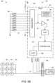
FIG. 1 is a block diagram of a system for measuring the temperature of transducer arrays that are used to apply TTFields to a subject's body. -
FIG. 2 is a schematic diagram of the hub in theFIG. 1 embodiment. -
FIG. 3 is a schematic diagram of one of the distal circuits in theFIG. 1 embodiment. -
FIG. 4A depicts a first option for connectorizing theFIG. 1 embodiment. -
FIG. 4B depicts a second option for connectorizing theFIG. 1 embodiment. -
FIG. 5A depicts a detailed view of the connector's position in theFIG. 4A embodiment. -
FIG. 5B depicts a detailed view of the connector's position in theFIG. 4B embodiment. -
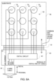
FIG. 6A depicts the mechanical layout for theFIG. 4A embodiment. -
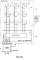
FIG. 6B depicts the mechanical layout for theFIG. 4B embodiment. - Various embodiments are described in detail below with reference to the accompanying drawings, wherein like reference numerals represent like elements.
-
FIG. 1 is a block diagram of an embodiment that relies ondistal circuits 40 positioned in close proximity to each of the fourtransducer arrays 50 to obtain the temperature readings from the temperature sensors in thetransducer arrays 50. Each of thetransducer arrays 50 includes a plurality of capacitively coupledelectrode elements 52 and a plurality of temperature sensors 54 (both shown inFIGS. 3 ,6A , and6B ). Thetemperature sensors 54 are positioned to detect the temperature atrespective electrode elements 52. In some preferred embodiments, thetemperature sensors 54 are thermistors. - Returning to
FIG. 1 , eachdistal circuit 40 interfaces with the temperature sensors that are incorporated into therespective transducer array 50 to obtain the temperature readings from each temperature sensor. Thedistal circuit 40 then analog-to-digital converts those temperature readings and forwards the digitized temperature readings along to acentral hub 30. Thecentral hub 30 then forwards these digitized temperature readings to thefield generator 20 via a serial communication link so that thefield generator 20 can determine, based on the temperature readings, if the current to thetransducer arrays 50 has to be adjusted. - There are 10 short conductors that extend distally in the
wiring 45 beyond thedistal circuit 40 into thetransducer array 50 itself. Those 10 conductors include 1 conductor for each of the 8 temperature sensors, 1 conductor for the temperature sensors' common ground, and 1 conductor for the TTFields signal (i.e., the AC current for the electrode elements). In some preferred embodiment, thedistal circuit 40 is implemented using a single-chip microcontroller or Programmable System on Chip (PSoC) with a built in analog front end and multiplexer. Suitable part numbers for this purpose include the CY8C4124LQI-443. In this case, no other active components are needed in thedistal circuit 40. In alternative embodiments, other microcontrollers may be used with either built-in or discrete analog front ends and multiplexers, as will be apparent to persons skilled in the relevant arts. The analog front end and multiplexer obtains temperature readings from the temperature sensors. Those temperature readings are then digitized and transmitted to thecentral hub 30, preferably via a serial data link. In addition, eachdistal circuit 40 also has an associated pass-through conductor (51, shown inFIGS. 3 and6A ) for routing the TTFields signal that originated in thefield generator 20 to thetransducer array 50. - In the
FIG. 1 embodiment, each of the fourdistal circuits 40 is connected to thecentral hub 30 via arespective cable 35. Notably only 4 conductors are required in each of thecables 35 that run between adistal circuit 40 and the hub 30 (i.e., one for Vcc, one for ground, one for serial data communication, and one for the TTFields signal). Thedistal circuits 40 therefore dramatically reduce the wire count that is needed to interface with eachtransducer array 50. -
FIG. 2 is a schematic diagram of a circuit that is suitable for use as thehub 30 depicted inFIG. 1 . In general terms, thehub 30 accepts the temperature readings from each of the distal circuits 40 (shown inFIG. 1 ) and sends those temperature readings along to the field generator 20 (shown inFIG. 1 ). Any of a wide variety of architectures may be used to accept and send the temperature readings. For example, in the illustrated embodiment, acontroller 32 sends a signal to adigital multiplexer 33 that commands thedigital multiplexer 33 to select one of the four inputs, which sets thehub 30 up to receive digital data from one of the distal circuits 40 (shown inFIG. 1 ). After that, thecontroller 32 accepts all eight temperature readings from the selected input and transmits those temperature readings along to the field generator 20 (shown inFIG. 1 ) via thetransceiver 34. After all the temperature readings from the selected input (i.e., the selected distal circuit) have been transmitted to the field generator, thecontroller 32 updates the control signal todigital multiplexer 33 and commands the digital multiplexer to select another one of the four inputs (i.e., another distal circuit). Thecontroller 32 then accepts all eight temperature readings from the newly selected input and transmits those temperature readings to the field generator. Corresponding sequences are then performed to obtain eight temperature readings from the third input and eight temperature readings from the fourth input. - In some preferred embodiments, the
controller 32, thedigital multiplexer 33, and thetransceiver 34 may be integrated together into a single chip. In alternative embodiments, thecontroller 32 and thedigital multiplexer 33 are integrated together into a single chip, and aseparate transceiver 34 is used. For example, thecontroller 32 and thedigital multiplexer 33 may be implemented using a Cypress CY8C4244LQI-443, and thetransceiver 34 may be implemented using a Linear Technology LTC2856CMS8-2#PBF. - The entire sequence of obtaining all of the temperature measurements from each of the four inputs is repeated periodically (e.g., every 1 second, 10 seconds, or 30 seconds) to update the temperature readings that are provided to the
field generator 20. Thehub 30 communicates with thefield generator 20 using any conventional communication technique (e.g., RS485). Thehub 30 also includes pass-throughconductors 31 that pass the TTField signals directly from thefield generator 20 to each of thetransducer arrays 50. In one example, thehub 30 communicates with thefield generator 20 via an 8-conductor spiral cable 25 (which includes 4 wires for TTFields signal from each array, 1 wire for ground, 1 wire for Vcc to thedistal circuits 40 and 2 wires for communication). Notably, this embodiment can be made backwards compatible with previous versions of TTField delivery systems. - In the embodiment described above, two wires are used to implement data communications between the
hub 30 and the field generator 20 (i.e., for the temperature data). This may be accomplished, for example, by using one wire to implement communication in each direction. In alternative embodiments, the wire count between thehub 30 and thefield generator 20 can be reduced by replacing the two data communication wires in the embodiments described above with a single data wire that implements two-way communication (using a conventional single wire communication protocol). -
FIG. 3 is a schematic diagram of a circuit for interfacing the hub (shown inFIG. 1 ) with any giventransducer array 50. Eachtransducer array 50 includes a plurality of capacitively coupledelectrode elements 52 and a plurality oftemperature sensors 54 positioned to sense temperatures at respective ones of the plurality of electrode elements. In some preferred embodiments, thesetemperature sensors 54 are thermistors. - An
analog multiplexer 81 has an analog output and a plurality of selectable analog inputs, and each of the plurality of the analog inputs is connected to a respective one of the plurality oftemperature sensors 54. The second terminal of eachtemperature sensor 54 goes to a common ground. The output of theanalog multiplexer 81 goes to anamplifier 82, preferably with a high input impedance (e.g., an op amp that is configured as a voltage follower). The output of theamplifier 82 is provided to the input of an analog todigital converter 83, and the output of the analog to digital converter is provided to acontroller 85. - The
controller 85 orchestrates the operation of all of the components within the dashedline 80. Thecontroller 85 sends a command to theanalog multiplexer 81 to select one of thetemperature sensors 54, in order to obtain a temperature reading from that temperature sensor. - In embodiments where thermistors are used as the
temperature sensors 54, temperature readings may be obtained by routing a known current through the thermistor and measuring the voltage that appears across the thermistor. In the illustrated embodiment, this may be achieved using a programmablecurrent source 88, which may be programmed to generate a known current (e.g., 150 µA). Theanalog multiplexer 81 is bidirectional, so this known current will be routed into whichever thermistor is selected by the analog multiplexer. - Temperature readings from all eight
temperature sensors 54 may be obtained using the following procedure. Thecontroller 85 sends a command to theanalog multiplexer 81 to select the first thermistor, and configures thecurrent source 88 to generate a known current. Because the first thermistor has been selected, the known current from thecurrent source 88 will flow through theanalog multiplexer 81 into the first thermistor. This will cause a voltage to appear across that thermistor. Because the first thermistor is selected, this voltage will appear at the output of theanalog multiplexer 81. Theamplifier 82 provides this voltage to the input of the analog todigital converter 83. Thecontroller 85 instructs the analog todigital converter 83 to digitize this voltage. Thecontroller 85 obtains this reading from the analog todigital converter 83 and temporarily stores the digitized reading (which corresponds to the first thermistor) in a buffer. This procedure is then repeated, sequentially, for each of the other thermistors until digitized readings from each of the eight thermistors are sitting in the buffer. - In alternative embodiments, not shown, an alternative approach (e.g., the conventional voltage divider approach) for interfacing with the thermistors may be used in place of the constant current approach described above. In other alternative embodiments, a different type of temperature sensor may be used in place of the thermistors described above. Examples include thermocouples, RTDs, and integrated circuit temperature sensors such as the Analog Devices AD590 and the Texas Instruments LM135. Of course, when any of these alternative temperature sensors is used, appropriate modifications to the circuit (which will be apparent to persons skilled in the relevant arts) will be required.
- In some embodiments, additional readings may be obtained and used for self-calibration to increase the accuracy of the temperature readings obtained from the thermistors. For example, in the illustrated embodiment, the bottom input of the
analog multiplexer 81 is connected to ground, and the top input of theanalog multiplexer 81 is connected to aprecision resistor 89. In some embodiments, theprecision resistor 89 is a 10 kOhm, 0.1% tolerance resistor. Readings from theprecision resistor 89 may be obtained using the same procedure described above for obtaining a reading from any one of the thermistors. Obtaining readings from the grounded input of theanalog multiplexer 81 is also similar, except that thecurrent source 88 may be deactivated when the grounded input is selected. In these embodiments, thecontroller 85 temporarily stores the digitized readings from the precision resistor and the grounded input in a buffer (which means that a total of 10 readings are stored in the buffer). These additional readings may ultimately be used to calibrate the readings that were obtained from the thermistors. In some embodiments, this calibration is implemented in thecontroller 85 itself, prior to transmission of the digital data that corresponds to the temperature readings. In other embodiments, this calibration is implemented in a downstream processor (e.g., thecontroller 32 in thehub 30, both shown inFIG. 2 ), in which case the digital data corresponding to the precision resistor (and optionally the grounded input) is transmitted to the downstream processor along with the uncalibrated temperature readings that were obtained from the thermistors. - One suitable approach for performing calibration using the
precision resistor 89 is to compare the actual voltage measured across that resistor with the expected voltage based on Ohm's law, the known value of theprecision resistor 89, and the expected value of the current being produced by thecurrent source 88. Any deviation between the actual measured voltage and the expected voltage could then be used as a multiplier for subsequent measurements from thethermistors 54. - The
controller 85 in thedistal circuit 40 communicates with the hub 30 (shown inFIG. 1 ) viaUART 86, and transmits the temperature readings obtained from thetemperature sensors 54 to the hub. In some embodiments, thecontroller 85 may be programmed to operate autonomously, in which case it would automatically collect temperature readings from each of thetemperature sensors 54 and store the result in a buffer as described above, and subsequently transmit the contents of the buffer (i.e., readings for each of the eighttemperature sensors 54, and optionally the additional readings described above) to the hub. - In alternative embodiments, the
controller 85 may be programmed to operate as a slave to a master controller located in the hub. In these embodiments, thecontroller 85 starts out in a quiescent state, where all it does is monitor incoming commands from the master controller that arrive via theUART 86. Examples of commands that can arrive from the master controller include a "collect samples" command and a "send data" command. When thecontroller 85 recognizes that a "collect samples" command has arrived, thecontroller 85 will initiate the procedure described above to obtain temperature readings from each of the eighttemperature sensors 54 and store the result in its buffer. When thecontroller 85 recognizes that a "send data" command has arrived, thecontroller 85 will execute a procedure that transmits the previously collected temperature readings from the buffer to the hub via theUART 86. - In those embodiments in which the
controller 85 operates as a slave to a master controller located in thehub 30, it becomes possible to synchronize the temperature measurements that are obtained from each of the four transducer arrays 50 (shown inFIG. 1 ). One way to accomplish this would be to have the master controller in thehub 30 send a "collect samples" command to all fourcontrollers 85 either simultaneously or in rapid succession, so that the temperature readings obtained from each of the transducer arrays will be obtained at or near the same time. The temperature readings can then be collected by thehub 30 in batches of eight from each of the fourcontrollers 85. - Most systems that use TTFields to treat tumors switch the direction of the field that is being applied to the tumor periodically (e.g. every second). To minimize noise in the temperature measurements, a small gap in time during which the field is not applied in either direction may be introduced, and the temperature measurements can be made during that gap in time. In some preferred embodiments, the master controller located in the
hub 30 synchronizes the timing of the "collect samples" command to all fourcontrollers 85 so that each of thedistal circuits 40 will obtain its temperature readings during this gap. In embodiments where the temperature readings are obtained from each of the four transducer arrays simultaneously, this approach can be used to minimize the duration of the gap. For example, if a system requires 100 µs to obtain a single measurement, taking all 32 measurements in sequence (i.e., 4 distal circuits × 8 thermistors at each circuit) would take 3.2 ms. In contrast, if each of the four distal circuits operates in parallel, each distal circuit can complete its job in 800 µs, in which case all 32 samples can be obtained in 800 µs. Note that because the "send data" command is not sensitive to noise, that command can be executed while the fields remain on, and is therefore not time-critical. - In some embodiments, some or all of the following components are implemented by a single integrated circuit:
analog multiplexer 81,amplifier 82, analog todigital converter 83,controller 85,UART 86, andcurrent source 88. One example of a single integrated circuit that includes all of these functional blocks is the Cypress CY8C4124LQI-443T programmable system on chip (PSoC). - Optionally, a connector may be included in the path between the
hub 30 and each of thetransducer arrays 50, as shown inFIGS. 4A and 4B for a single transducer array. In theFIG. 4A embodiment, aconnector 42 is positioned distally beyond thedistal circuit 40; and in theFIG. 4B embodiment, aconnector 38 is positioned on the proximal side of thedistal circuit 40. -
FIG. 5A depicts a more detailed view to show exactly where theconnector 42 is positioned in theFIG. 4A embodiment. In this embodiment, theconnector 42 is positioned distally beyond thedistal circuit 40. Operation of theFIG. 5A embodiment is similar to the operation of theFIG. 3 embodiment discussed above, except that 10 signals traverse the connector 42: one for the AC current that goes to theelectrode elements 52; one for each of the eight temperature sensors 54 (for a subtotal of eight); and one for a common ground that is used for all of the eighttemperature sensors 54. -
FIG. 5B depicts a more detailed view to show exactly where theconnector 38 is positioned in theFIG. 4B embodiment. In this embodiment, theconnector 38 is positioned on the proximal side of thedistal circuit 40. Operation of theFIG. 5B embodiment is similar to the operation of theFIG. 3 embodiment discussed above, except that 4 signals traverse the connector 38: one for the AC current that goes to theelectrode elements 52, one for data that travels between theUART 86 and the hub; one for power to thedistal circuit 40, and one for ground for thedistal circuit 40. -
FIG. 6A depicts the mechanical layout for theFIG. 4A /5A embodiment. In this embodiment, asubstrate 59 supports a plurality of capacitively coupledelectrode elements 52. Theelectrode elements 52 are configured for placement against the subject's body, and thesubstrate 59 is configured to hold the plurality ofelectrode elements 52 against the subject's body. A plurality oftemperature sensors 54 are positioned adjacent to and/or beneath respective ones of theelectrode elements 52 so that thetemperature sensors 54 can sense the temperatures of those electrode elements. - A
cable 35 has a proximal end and a distal end. Thiscable 35 includes (i) aconductor 51 that permits AC current to flow between the proximal end of the cable and the distal end of the cable and (ii) a data path configured to carry the digital data corresponding to the plurality of temperature readings (which originates in the distal circuit 40) from the distal end of the cable to the proximal end of the cable (i.e., in the direction of the hub). - A
module 60 is mounted (either directly or through intervening components) to the distal end of thecable 35. Thedistal circuit 40 is mounted in thismodule 60. In some embodiments, power and ground for thedistal circuit 40 is provided through thecable 35. A first half of aconnector 42 is provided at the distal end of themodule 60, and the second half of theconnector 42 is provided on thesubstrate 59. The first half of theconnector 42 mates with the second half of theconnector 42 so that electrical signals can pass through both halves of theconnector 42. When both halves of theconnector 42 are mated, signals from the eightthermistors 54 will travel through wiring on thesubstrate 59, through theconnector 42, and into thedistal circuit 40. Thisdistal circuit 40 includes the analog multiplexer, the analog to digital converter, and the controller (described above in connection withFIG. 3 ). In addition, a common ground signal for all thethermistors 54 is provided through theconnector 42. A path for the AC current for theelectrode elements 52 is also provided through theconnector 42. This path continues through appropriate wiring on thesubstrate 59 so that the plurality ofelectrode elements 52 will be electrically connected to a corresponding conductor of thecable 35. -
FIG. 6B depicts the mechanical layout for theFIG. 4B /5B embodiment. In this embodiment, asubstrate 59 supports a plurality of capacitively coupledelectrode elements 52. Theelectrode elements 52 are configured for placement against the subject's body, and thesubstrate 59 is configured to hold the plurality ofelectrode elements 52 against the subject's body. A plurality oftemperature sensors 54 are positioned adjacent to and/or beneath respective ones of theelectrode elements 52 so that thetemperature sensors 54 can sense the temperatures of those electrode elements. - A
cable 35 has a proximal end and a distal end. Thiscable 35 includes (i) aconductor 51 that permits AC current to flow between the proximal end of the cable and the distal end of the cable and (ii) a data path configured to carry the digital data corresponding to the plurality of temperature readings (which originates in the distal circuit 40) from the distal end of the cable to the proximal end of the cable (i.e., in the direction of the hub). - A
module 65 is mounted (either directly or through intervening components) to thesubstrate 59. Thedistal circuit 40 is mounted in thismodule 65. In some embodiments, power and ground for thedistal circuit 40 are provided through thecable 35. A first half of aconnector 38 is provided at the distal end of thecable 35, and the second half of theconnector 38 is provided on thesubstrate 59. The first half of theconnector 38 mates with the second half of theconnector 38 so that electrical signals can pass through both halves of theconnector 38. When both halves of theconnector 38 are mated, signals from thecable 35 will travel through theconnector 38, and into thedistal circuit 40. Thisdistal circuit 40 includes the analog multiplexer, the analog to digital converter, and the controller (described above in connection withFIG. 3 ). In addition, a path for the AC current for theelectrode elements 52 is also provided through theconnector 38. This path continues through appropriate wiring on thesubstrate 59 so that the plurality ofelectrode elements 52 will be electrically connected to a corresponding conductor of thecable 35. - The connectorized design depicted in
FIGS. 4-6 provides a significant advantage over non-connectorized embodiments in that the patient or caregiver can attach thetransducer arrays 50 to the patient's skin without being hindered by the presence of cables. In these embodiments, thecables 35 are preferably disconnected from thesubstrates 59 when thetransducer arrays 50 are initially placed on the patient's body. Only after thetransducer arrays 50 are affixed in their desired positions are thecables 35 connected to thetransducer arrays 50 via theconnectors - Note that the
FIG. 4A /5A /6A embodiment has an advantage over both the non-connectorizedFIG. 1 embodiment and theFIG. 4B /5B /6B embodiment because thetransducer arrays 50 are preferably sterilized before use. Sterilization is ordinarily performed using either radiation or gas. Since radiation can interfere with electronics, assemblies in which thedistal circuit 40 cannot be disconnected from thetransducer arrays 50 can only be sterilized with gas. On the other hand, if thedistal circuit 40 is located on the proximal side of the connector 42 (as it is in theFIG. 4A /5A /6A embodiment), the portion that includes thedistal circuit 40 will not require sterilization. This permits sterilization of thetransducer arrays 50 in theFIG. 4A /5A /6A embodiment to be performed using either gas or radiation without risk of damage to thedistal circuit 40. - Each of the configurations described above has significant advantages over the prior art because only 4 conductors are needed in each of the
cables 35 that interface with eachtransducer array 50. Furthermore, because only 4 conductors are required, thecables 35 that extend distally beyond thehub 30 can be made thinner and smaller than the prior art cables. This makes it easier to mount thehub 30 on a portion of the body that is adjacent to thetransducer arrays 50, and to make small and lightweight interconnections between thehub 30 and thetransducer arrays 50. For example, when thetransducer arrays 50 are affixed to the patient's scalp, it becomes possible to mount thehub 30 on the patient's head in the vicinity of thetransducer arrays 50 without discomfort to the patient. In these embodiments, shorter cables 35 (e.g., less than 25 cm or even less than 10 cm) are preferably used to interconnect thehub 30 with both thetransducer arrays 50 and thedistal circuit 40. - The configurations described herein can advantageously reduce tangling of the cables that lead to the
transducer arrays 50, reduce the number of times that the cables will interfere with patients' everyday activities, reduce the overall cumbersomeness of the system, improve patient comfort, and improve maneuverability of the electrodes when they are affixed to the patient's body. - Returning to
FIG. 1 , a display unit (not shown) may be added to the system. This display unit may be used to display information that the device provides to the patient including but not limited to device status (e.g., on/standby), error indications, status of battery charge, compliance metrics, etc. The display unit may be mounted at any point along thecable 25 between thehub 30 and thefield generator 20. In alternative embodiments, the display unit 22 may be mounted to thehub 30 itself. - In some alternative embodiments, the wires that provide power and ground to the
distal circuit 40 can also be eliminated by diverting some of the energy from the TTFields signal (which is delivered via pass-through conductors) using a coil, storing that energy in a capacitor adjacent to thedistal circuit 40, and powering thedistal circuit 40 using the stored energy. It is even possible to implement a one-wire communication protocol that transmits the temperature data over the TTFields signal wire. In such a configuration, the data communication signals and power for the distal circuits (Vcc) could all be removed from the cable that runs to thetransducer array 50. If all of these wire reduction techniques are implemented, only two wires will be needed between thehub 30 and each transducer array 50 (i.e., 1 for the TTField signal and 1 for ground). And the total number of wires that run back from the fourtransducer arrays 50 to thefield generator 20 would be reduced to 5 (i.e., 1 for a common ground and a total of 4 for the TTField signals). - While the present invention has been disclosed with reference to certain embodiments, numerous modifications, alterations, and changes to the described embodiments are possible without departing from the sphere and scope of the present invention, as defined in the appended claims. Accordingly, it is intended that the present invention not be limited to the described embodiments, but that it has the full scope defined by the language of the following claims, and equivalents thereof.
- Furthermore, the present invention is represented by the following statements of invention.
- 1. An apparatus for use together with an AC signal generator for imposing electric fields through a target region in a subject's body, the apparatus comprising:
- a plurality of capacitively coupled electrode elements configured for placement against the subject's body;
- a substrate configured to hold the plurality of electrode elements against the subject's body;
- a plurality of temperature sensors positioned to sense temperatures at respective ones of the plurality of electrode elements;
- an analog multiplexer having an analog output and a plurality of selectable analog inputs, wherein each of the plurality of analog inputs is operatively connected to a respective one of the plurality of temperature sensors;
- an analog to digital converter configured to digitize signals arriving from the analog output;
- a controller configured to (a) sequentially select each of the plurality of analog inputs, (b) sequentially obtain, from the analog to digital converter, a plurality of temperature readings, each of the plurality of temperature readings corresponding to a respective one of the plurality of temperature sensors, and (c) transmit digital data corresponding to the plurality of temperature readings; and
- a cable having a proximal end and a distal end, wherein the cable includes (i) a conductor that permits AC current to flow between the proximal end of the cable and the distal end of the cable and (ii) a data path configured to carry the transmitted digital data from the distal end of the cable to the proximal end of the cable, the plurality of electrode elements are electrically connected to the conductor, and the analog multiplexer, the analog to digital converter and the controller are mounted to the substrate or to the distal end of the cable.
- 2. The apparatus of
statement 1, wherein the plurality of temperature sensors comprise a plurality of thermistors. - 3. The apparatus of
statement 1, wherein the cable has a length of 25 cm or less. - 4. The apparatus of
statement 1, wherein the cable has a length of 10 cm or less. - 5. The apparatus of
statement 1, further comprising:
a connector disposed between the controller and the distal end of the cable. - 6. The apparatus of statement 5, wherein the analog multiplexer, the analog to digital converter and the controller are mounted to the substrate.
- 7. The apparatus of
statement 1, further comprising:
a connector disposed between the plurality of temperature sensors and the plurality of analog inputs. - 8. The apparatus of statement 7, wherein the analog multiplexer, the analog to digital converter and the controller are mounted to the distal end of the cable.
- 9. The apparatus of
statement 1, further comprising:- a precision resistor, wherein the analog multiplexer has an additional selectable analog input that is operatively connected to the precision resistor, and the controller is further configured to (d) select the additional analog input, (e) obtain,
- from the analog to digital converter, an additional reading that corresponds to the precision resistor, and (f) transmit digital data corresponding to the additional reading.
- 10. The apparatus of
statement 1, further comprising:- a precision resistor, wherein the analog multiplexer has an additional selectable analog input that is operatively connected to the precision resistor, and the controller is further configured to (d) select the additional analog input, (e) obtain,
- from the analog to digital converter, an additional reading that corresponds to the precision resistor, and (f) calibrate, based on the additional reading, each of the plurality of temperature readings prior to transmission of the corresponding digital data.
- 11. The apparatus of
statement 1, wherein the cable uses a single conductor to provide the data path that carries the transmitted digital data from the distal end of the cable to the proximal end of the cable. - 12. The apparatus of
statement 1, wherein the cable uses a single conductor to provide the data path that carries the transmitted digital data from the distal end of the cable to the proximal end of the cable, a single conductor for providing power to the controller and a single conductor for ground. - 13. The apparatus of
statement 1, wherein energy arriving via the conductor in the cable is used to power the controller. - 14. An apparatus for use together with an AC signal generator for imposing electric fields through a target region in a subject's body, the apparatus comprising:
- a hub configured to accept digital data corresponding to first, second, third and fourth pluralities of temperature readings and output digital data corresponding to the first, second, third and fourth pluralities of temperature readings to the AC signal generator, wherein the hub includes first, second, third and fourth conductors configured to route current from the AC signal generator to positions that are located distally beyond the hub;
- a first plurality of capacitively coupled electrode elements configured for placement against the subject's body at a first position;
- a first substrate configured to hold the first plurality of electrode elements against the subject's body at the first position;
- a first plurality of temperature sensors positioned to sense temperatures at respective ones of the first plurality of electrode elements;
- a first analog multiplexer having a first analog output and a first plurality of selectable analog inputs, wherein each of the first plurality of analog inputs is operatively connected to a respective one of the first plurality of temperature sensors;
- a first analog to digital converter configured to digitize signals arriving from the first analog output;
- a first controller configured to (a) sequentially select each of the first plurality of analog inputs, (b) sequentially obtain, from the first analog to digital converter, a first plurality of temperature readings, each of the first plurality of temperature readings corresponding to a respective one of the first plurality of temperature sensors, and (c) transmit first digital data corresponding to the first plurality of temperature readings to the hub;
- a first cable arranged to route current arriving via the first conductor in the hub to the first plurality of electrode elements and to route the first digital data from the first controller to the hub;
- a second plurality of capacitively coupled electrode elements configured for placement against the subject's body at a second position;
- a second substrate configured to hold the second plurality of electrode elements against the subject's body at the second position;
- a second plurality of temperature sensors positioned to sense temperatures at respective ones of the second plurality of electrode elements;
- a second analog multiplexer having a second analog output and a second plurality of selectable analog inputs, wherein each of the second plurality of analog inputs is operatively connected to a respective one of the second plurality of temperature sensors;
- a second analog to digital converter configured to digitize signals arriving from the second analog output;
- a second controller configured to (a) sequentially select each of the second plurality of analog inputs, (b) sequentially obtain, from the second analog to digital converter, a second plurality of temperature readings, each of the second plurality of temperature readings corresponding to a respective one of the second plurality of temperature sensors, and (c) transmit second digital data corresponding to the second plurality of temperature readings to the hub;
- a second cable arranged to route current arriving via the second conductor in the hub to the second plurality of electrode elements and to route the second digital data from the second controller to the hub;
- a third plurality of capacitively coupled electrode elements configured for placement against the subject's body at a third position;
- a third substrate configured to hold the third plurality of electrode elements against the subject's body at the third position;
- a third plurality of temperature sensors positioned to sense temperatures at respective ones of the third plurality of electrode elements;
- a third analog multiplexer having a third analog output and a third plurality of selectable analog inputs, wherein each of the third plurality of analog inputs is operatively connected to a respective one of the third plurality of temperature sensors;
- a third analog to digital converter configured to digitize signals arriving from the third analog output;
- a third controller configured to (a) sequentially select each of the third plurality of analog inputs, (b) sequentially obtain, from the third analog to digital converter, a third plurality of temperature readings, each of the third plurality of temperature readings corresponding to a respective one of the third plurality of temperature sensors, and (c) transmit third digital data corresponding to the third plurality of temperature readings to the hub;
- a third cable arranged to route current arriving via the third conductor in the hub to the third plurality of electrode elements and to route the third digital data from the third controller to the hub;
- a fourth plurality of capacitively coupled electrode elements configured for placement against the subject's body at a fourth position;
- a fourth substrate configured to hold the fourth plurality of electrode elements against the subject's body at the fourth position;
- a fourth plurality of temperature sensors positioned to sense temperatures at respective ones of the fourth plurality of electrode elements;
- a fourth analog multiplexer having a fourth analog output and a fourth plurality of selectable analog inputs, wherein each of the fourth plurality of analog inputs is operatively connected to a respective one of the fourth plurality of temperature sensors;
- a fourth analog to digital converter configured to digitize signals arriving from the fourth analog output;
- a fourth controller configured to (a) sequentially select each of the fourth plurality of analog inputs, (b) sequentially obtain, from the fourth analog to digital converter, a fourth plurality of temperature readings, each of the fourth plurality of temperature readings corresponding to a respective one of the fourth plurality of temperature sensors, and (c) transmit fourth digital data corresponding to the fourth plurality of temperature readings to the hub; and
- a fourth cable arranged to route current arriving via the fourth conductor in the hub to the fourth plurality of electrode elements and to route the fourth digital data from the fourth controller to the hub.
- 15. The apparatus of statement 14, wherein the first, second, third and fourth controllers are synchronized so that the first, second, third and fourth pluralities of temperature readings are obtained simultaneously.
- 16. The apparatus of statement 14, wherein the first, second, third and fourth controllers are synchronized so that at least a portion of the first, second, third and fourth pluralities of temperature readings are obtained simultaneously.
- 17. The apparatus of statement 14, further comprising:
- a first precision resistor;
- a second precision resistor;
- a third precision resistor; and
- a fourth precision resistor;
- wherein the first analog multiplexer has a first additional selectable analog input that is operatively connected to the first precision resistor, and the first controller is further configured to (d) select the first additional analog input, (e) obtain, from the first analog to digital converter, a first additional reading that corresponds to the first precision resistor, and (f) transmit digital data corresponding to the first additional reading to the hub,
- wherein the second analog multiplexer has a second additional selectable analog input that is operatively connected to the second precision resistor, and the second controller is further configured to (d) select the second additional analog input, (e) obtain, from the second analog to digital converter, a second additional reading that corresponds to the second precision resistor, and (f) transmit digital data corresponding to the second additional reading to the hub,
- wherein the third analog multiplexer has a third additional selectable analog input that is operatively connected to the third precision resistor, and the third controller is further configured to (d) select the third additional analog input, (e) obtain, from the third analog to digital converter, a third additional reading that corresponds to the third precision resistor, and (f) transmit digital data corresponding to the third additional reading to the hub, and
- wherein the fourth analog multiplexer has a fourth additional selectable analog input that is operatively connected to the fourth precision resistor, and the fourth controller is further configured to (d) select the fourth additional analog input, (e) obtain, from the fourth analog to digital converter, a fourth additional reading that corresponds to the fourth precision resistor, and (f) transmit digital data corresponding to the fourth additional reading to the hub.
- 18. The apparatus of statement 17, wherein the hub is further configured to:
- calibrate, based on the first additional reading, each of the plurality of first temperature readings,
- calibrate, based on the second additional reading, each of the plurality of second temperature readings,
- calibrate, based on the third additional reading, each of the plurality of third temperature readings, and
- calibrate, based on the fourth additional reading, each of the plurality of fourth temperature readings.
- 19. The apparatus of statement 14, further comprising:
- a first precision resistor;
- a second precision resistor;
- a third precision resistor; and
- a fourth precision resistor;
- wherein the first analog multiplexer has a first additional selectable analog input that is operatively connected to the first precision resistor, and the first controller is further configured to (d) select the first additional analog input, (e) obtain, from the first analog to digital converter, a first additional reading that corresponds to the first precision resistor, and (f) calibrate, based on the first additional reading, each of the plurality of first temperature readings prior to transmission of the corresponding digital data to the hub,
- wherein the second analog multiplexer has a second additional selectable analog input that is operatively connected to the second precision resistor, and the second controller is further configured to (d) select the second additional analog input, (e) obtain, from the second analog to digital converter, a second additional reading that corresponds to the second precision resistor, and (f) calibrate, based on the second additional reading, each of the plurality of second temperature readings prior to transmission of the corresponding digital data to the hub,
- wherein the third analog multiplexer has a third additional selectable analog input that is operatively connected to the third precision resistor, and the third controller is further configured to (d) select the third additional analog input, (e) obtain, from the third analog to digital converter, a third additional reading that corresponds to the third precision resistor, and (f) calibrate, based on the third additional reading, each of the plurality of third temperature readings prior to transmission of the corresponding digital data to the hub,
- wherein the fourth analog multiplexer has a fourth additional selectable analog input that is operatively connected to the fourth precision resistor, and the fourth controller is further configured to (d) select the fourth additional analog input, (e) obtain, from the fourth analog to digital converter, a fourth additional reading that corresponds to the fourth precision resistor, and (f) calibrate, based on the fourth additional reading, each of the plurality of fourth temperature readings prior to transmission of the corresponding digital data to the hub.
- 20. The apparatus of statement 14, further comprising:
- a first connector disposed between the first controller and the hub;
- a second connector disposed between the second controller and the hub;
- a third connector disposed between the third controller and the hub; and
- a fourth connector disposed between the fourth controller and the hub.
- 21. The apparatus of statement 14, further comprising:
- a first connector disposed between the first plurality of temperature sensors and the first plurality of analog inputs;
- a second connector disposed between the second plurality of temperature sensors and the second plurality of analog inputs;
- a third connector disposed between the third plurality of temperature sensors and the third plurality of analog inputs; and
- a fourth connector disposed between the fourth plurality of temperature sensors and the fourth plurality of analog inputs.
- 22. The apparatus of statement 14, wherein the first cable uses a single conductor for routing current arriving via the first conductor in the hub to the first plurality of electrode elements and a single conductor for transferring digital data between the first controller and the hub, the second cable uses a single conductor for routing current arriving via the second conductor in the hub to the second plurality of electrode elements and a single conductor for transferring digital data between the second controller and the hub, the third cable uses a single conductor for routing current arriving via the third conductor in the hub to the third plurality of electrode elements and a single conductor for transferring digital data between the third controller and the hub, and the fourth cable uses a single conductor for routing current arriving via the fourth conductor in the hub to the fourth plurality of electrode elements and a single conductor for transferring digital data between the fourth controller and the hub.
- 23. The apparatus of statement 14, wherein the first cable uses a single conductor for routing current arriving via the first conductor in the hub to the first plurality of electrode elements, a single conductor for transferring digital data between the first controller and the hub, a single conductor for providing power to the first controller and a single conductor for ground, the second cable uses a single conductor for routing current arriving via the second conductor in the hub to the second plurality of electrode elements, a single conductor for transferring digital data between the second controller and the hub, a single conductor for providing power to the second controller and a single conductor for ground, the third cable uses a single conductor for routing current arriving via the third conductor in the hub to the third plurality of electrode elements, a single conductor for transferring digital data between the third controller and the hub, a single conductor for providing power to the third controller and a single conductor for ground, and the fourth cable uses a single conductor for routing current arriving via the fourth conductor in the hub to the fourth plurality of electrode elements, a single conductor for transferring digital data between the fourth controller and the hub, a single conductor for providing power to the fourth controller and a single conductor for ground.
- 24. The apparatus of statement 14, wherein energy arriving via the first, second, third and fourth conductors in the hub is used to power the first, second, third and fourth controllers, respectively.
Claims (6)
- An apparatus for use together with an AC signal generator (20) for imposing TTFields through a target region in a subject's body, the apparatus comprising:a plurality of transducer arrays (50) for applying TTFields to a subject's body, each transducer array (50) comprising:a plurality of capacitively-coupled electrode elements (52) configured for placement against the subject's body at one of the respective positions;a substrate (59) configured to hold the electrode elements (52) against the subject's body at the one of the respective positions; anda plurality of temperature sensors (54) positioned to sense temperatures at respective ones of the electrode elements (52); anda plurality of cables (35) interfacing the transducer arrays (50) and the AC signal generator (20), wherein the cables (35) each include a conductor (51) that passes AC current to the respective transducer array (50); anda plurality of distal circuits (40), each distal circuit (40) interfacing with a respective one of the transducer arrays (50) and being powered by diverting some of the energy from the imposed TTFields and storing energy in a capacitor adjacent the distal circuit (40).
- The apparatus of claim 1, further comprising:
a hub (30) configured to accept digital data corresponding to pluralities of temperature readings from the transducer arrays (50) and output digital data corresponding to each of the temperature readings to the AC signal generator (20), wherein the hub (30) includes a plurality of conductors configured to route current from the AC signal generator (20) to the respective transducer arrays (50). - The apparatus of claim 2, wherein the distal circuits (40) each comprise:an analog multiplexer (81) having an analog output and a plurality of selectable analog inputs, wherein each of the analog inputs of the analog multiplexer (81) is operatively connected to a respective one of the temperature sensors (54);an analog-to-digital converter (83) configured to digitize signals from the analog output of the analog multiplexer (81); anda controller (85) configured to sequentially select each of the analog inputs of the analog multiplexer (81), sequentially obtain, from the analog-to-digital converter (83), a plurality of temperature readings, each of the temperature readings corresponding to a respective one of the temperature sensors (54), and transmit digital data corresponding to the temperature readings to the hub (30).
- The apparatus of claim 3, wherein each transducer array (50) further comprises:
a connector (38; 42) disposed between the controller (85) and the hub (30). - The apparatus of claim 3, wherein the cable (35) uses a single conductor for routing current via the respective conductor in the hub (30) to the electrode elements (52) and a single conductor for transferring digital data between the controller (85) and the hub (30).
- The apparatus of claim 3, wherein each cable (35) uses a single conductor for routing current via the respective conductor in the hub (30) to the electrode elements (52), a single conductor for transferring digital data between the controller (85) and the hub (30), a single conductor for providing power to the controller (85) and a single conductor for ground.
Applications Claiming Priority (3)
| Application Number | Priority Date | Filing Date | Title |
|---|---|---|---|
| US201662376885P | 2016-08-18 | 2016-08-18 | |
| PCT/IB2017/054922 WO2018033842A1 (en) | 2016-08-18 | 2017-08-11 | Temperature measurement in arrays for delivering ttfields |
| EP17767932.1A EP3500334B1 (en) | 2016-08-18 | 2017-08-11 | Temperature measurement in arrays for delivering ttfields |
Related Parent Applications (2)
| Application Number | Title | Priority Date | Filing Date |
|---|---|---|---|
| EP17767932.1A Division EP3500334B1 (en) | 2016-08-18 | 2017-08-11 | Temperature measurement in arrays for delivering ttfields |
| EP17767932.1A Division-Into EP3500334B1 (en) | 2016-08-18 | 2017-08-11 | Temperature measurement in arrays for delivering ttfields |
Publications (1)
| Publication Number | Publication Date |
|---|---|
| EP4218908A1 true EP4218908A1 (en) | 2023-08-02 |
Family
ID=59859422
Family Applications (6)
| Application Number | Title | Priority Date | Filing Date |
|---|---|---|---|
| EP23168147.9A Pending EP4218907A1 (en) | 2016-08-18 | 2017-08-11 | Temperature measurement in arrays for delivering tumour treating fields |
| EP23168146.1A Pending EP4218906A1 (en) | 2016-08-18 | 2017-08-11 | Temperature measurement in arrays for delivering tumour treating fields |
| EP17767932.1A Active EP3500334B1 (en) | 2016-08-18 | 2017-08-11 | Temperature measurement in arrays for delivering ttfields |
| EP23168148.7A Pending EP4218908A1 (en) | 2016-08-18 | 2017-08-11 | Temperature measurement in arrays for delivering ttfields |
| EP23168145.3A Pending EP4218905A1 (en) | 2016-08-18 | 2017-08-11 | Temperature measurement in arrays for delivering tumour treating fields |
| EP23168144.6A Pending EP4218904A1 (en) | 2016-08-18 | 2017-08-11 | Temperature measurement in arrays for delivering tumour treating fields |
Family Applications Before (3)
| Application Number | Title | Priority Date | Filing Date |
|---|---|---|---|
| EP23168147.9A Pending EP4218907A1 (en) | 2016-08-18 | 2017-08-11 | Temperature measurement in arrays for delivering tumour treating fields |
| EP23168146.1A Pending EP4218906A1 (en) | 2016-08-18 | 2017-08-11 | Temperature measurement in arrays for delivering tumour treating fields |
| EP17767932.1A Active EP3500334B1 (en) | 2016-08-18 | 2017-08-11 | Temperature measurement in arrays for delivering ttfields |
Family Applications After (2)
| Application Number | Title | Priority Date | Filing Date |
|---|---|---|---|
| EP23168145.3A Pending EP4218905A1 (en) | 2016-08-18 | 2017-08-11 | Temperature measurement in arrays for delivering tumour treating fields |
| EP23168144.6A Pending EP4218904A1 (en) | 2016-08-18 | 2017-08-11 | Temperature measurement in arrays for delivering tumour treating fields |
Country Status (15)
| Country | Link |
|---|---|
| US (2) | US11097101B2 (en) |
| EP (6) | EP4218907A1 (en) |
| JP (6) | JP7148495B2 (en) |
| KR (2) | KR102580614B1 (en) |
| CN (3) | CN116747438A (en) |
| AU (1) | AU2017313423B2 (en) |
| BR (1) | BR112019003199A2 (en) |
| CA (1) | CA3032571C (en) |
| DK (1) | DK3500334T3 (en) |
| ES (1) | ES2959582T3 (en) |
| FI (1) | FI3500334T3 (en) |
| HU (1) | HUE063481T2 (en) |
| NZ (1) | NZ750440A (en) |
| PL (1) | PL3500334T3 (en) |
| WO (1) | WO2018033842A1 (en) |
Families Citing this family (57)
| Publication number | Priority date | Publication date | Assignee | Title |
|---|---|---|---|---|
| US10779875B2 (en) | 2013-05-06 | 2020-09-22 | Novocure Gmbh | Optimizing treatment using TTfields by changing the frequency during the course of long term tumor treatment |
| US20190117963A1 (en) * | 2014-07-25 | 2019-04-25 | Loyalty Based Innovations, LLC | Apparatus and method for treating multiple tumors in patients with metastatic disease by electric fields |
| US10188851B2 (en) | 2015-10-28 | 2019-01-29 | Novocure Limited | TTField treatment with optimization of electrode positions on the head based on MRI-based conductivity measurements |
| US10821283B2 (en) | 2016-04-04 | 2020-11-03 | Novocure Gmbh | Reducing motility of cancer cells using tumor treating fields (TTFields) |
| CA3029468A1 (en) | 2016-06-30 | 2018-01-04 | Zeev Bomzon | Arrays for longitudinal delivery of ttfields to a body |
| WO2018134733A1 (en) | 2017-01-19 | 2018-07-26 | Moshe Giladi | System for viewing cell cultures under a microscope whilst applying ttfields |
| US11338135B2 (en) | 2017-10-23 | 2022-05-24 | Cardiac Pacemakers, Inc. | Medical devices for cancer therapy with electric field shaping elements |
| US10953209B2 (en) | 2018-03-28 | 2021-03-23 | Board Of Regents Of The University Of Texas System | Treating tumors using TTFields combined with a PARP inhibitor |
| JP7139448B2 (en) | 2018-04-09 | 2022-09-20 | ノボキュア ゲーエムベーハー | Treatment of Tumors with TTFields and Aurora Kinase Inhibitors |
| KR20200141478A (en) | 2018-04-10 | 2020-12-18 | 지브 봄존 | Low frequency AC conductance estimates of less than 1 MHz obtained from two MRI images with different repetition times |
| CN116603165A (en) | 2018-07-03 | 2023-08-18 | 斯坦福大学托管董事会 | Enhancement of cell membrane permeability using alternating electric fields |
| CA3103070C (en) | 2018-07-10 | 2024-01-09 | Novocure Gmbh | Inhibiting viral infection using alternating electric fields |
| US11179322B2 (en) | 2018-07-10 | 2021-11-23 | Novocure Gmbh | Methods and compositions for treating tumors with TTFields and sorafenib |
| JP7267393B2 (en) | 2018-07-18 | 2023-05-01 | ノボキュア ゲーエムベーハー | Use of Power Loss Density and Associated Treatments to Quantify Tumor Treatment Field (TT Field) Dose |
| DK3804648T3 (en) | 2018-08-23 | 2022-04-11 | Novocure Gmbh | USE OF ELECTRIC AC FIELDS TO INCREASE THE PERMEABILITY OF THE BLOOD-BRAIN BARRIER |
| US11160977B2 (en) | 2018-09-04 | 2021-11-02 | Novocure Gmbh | Delivering tumor treating fields (TTFields) to the infratentorial brain |
| JP2022501098A (en) | 2018-09-07 | 2022-01-06 | ノボキュア ゲーエムベーハー | Treatment of autoimmune diseases using an alternating electric field that reduces T cell proliferation |
| EP3984590B1 (en) | 2018-10-15 | 2022-12-07 | Novocure GmbH | Generating tumor treating fields (ttfields) with high uniformity throughout the brain |
| EP3870271A1 (en) | 2018-10-25 | 2021-09-01 | Zeev Bomzon | Delivering alternating electric fields (e.g., ttfields) to a subject's spinal anatomy |
| AU2019371341A1 (en) * | 2018-11-01 | 2021-06-03 | Lifebridge Innovations, Pbc | Apparatus and method for treating multiple tumors in patients with metastatic disease by electric fields |
| MX2021002624A (en) | 2018-11-19 | 2021-05-12 | Novocure Gmbh | Arrays for delivering tumor treating fields (ttfields) with selectively addressable sub-elements. |
| CA3110453C (en) | 2018-11-29 | 2024-02-27 | Novocure Gmbh | Enhanced-flexibility transducer arrays for delivering ttfields (tumor treating fields) |
| EP3961565A1 (en) | 2019-01-08 | 2022-03-02 | Novocure GmbH | Evaluating quality of segmentation of an image into different types of tissue for planning treatment using tumor treating fields (ttfields) |
| CN113573774A (en) | 2019-02-26 | 2021-10-29 | 诺沃库勒有限责任公司 | Determining frequency of TTfield therapy based on electrical properties of targeted cancer cells |
| CN113453638A (en) | 2019-02-27 | 2021-09-28 | 诺沃库勒有限责任公司 | Delivering tumor therapy fields (TTfields) using an implantable transducer array |
| JP7419391B2 (en) | 2019-03-29 | 2024-01-22 | ノボキュア ゲーエムベーハー | Method for restoring sensitivity to TTFields in TTFields-resistant cancer cells by PTGER3 inhibitors |
| PL3960232T3 (en) * | 2019-04-17 | 2023-05-15 | Novocure Gmbh | Uploading data from an isolated system without compromising isolation |
| EP3958959B1 (en) | 2019-04-22 | 2024-04-24 | Boston Scientific Scimed Inc. | Devices for administering electrical stimulation to treat cancer |
| CN113727753A (en) | 2019-04-22 | 2021-11-30 | 波士顿科学国际有限公司 | Electrical stimulation device for cancer treatment |
| WO2020219517A2 (en) | 2019-04-23 | 2020-10-29 | Boston Scientific Scimed, Inc. | Electrical stimulation for cancer treatment with internal and external electrodes |
| JP2022529374A (en) | 2019-04-23 | 2022-06-21 | ボストン サイエンティフィック サイムド,インコーポレイテッド | Electrodes for electrical stimulation for cancer treatment |
| EP3958960A1 (en) | 2019-04-23 | 2022-03-02 | Boston Scientific Scimed Inc. | Electrical stimulation with thermal treatment or thermal monitoring |
| WO2021019403A1 (en) * | 2019-07-31 | 2021-02-04 | Yoram Wasserman | Applying tumor treating fields (ttfields) via electrodes embedded into skull implants |
| JP2022545794A (en) | 2019-08-30 | 2022-10-31 | ノボキュア ゲーエムベーハー | Application of tumor therapeutic fields (TTFields) to the neck |
| US11439816B2 (en) * | 2019-12-20 | 2022-09-13 | Novocure Gmbh | Treatment assembly for providing tumor treating fields to animal test subjects |
| KR20220122679A (en) | 2019-12-31 | 2022-09-02 | 노보큐어 게엠베하 | High-voltage, high-efficiency sine wave generator that avoids spikes during switching and amplitude adjustment of channels |
| CN114901344A (en) | 2019-12-31 | 2022-08-12 | 诺沃库勒有限责任公司 | Array for delivering a tumor therapy field (TT field) with individually accessible electrode elements and temperature sensors |
| CN115515674A (en) | 2020-02-24 | 2022-12-23 | 波士顿科学国际有限公司 | Systems and methods for treating pancreatic cancer |
| KR102464313B1 (en) | 2020-05-18 | 2022-11-08 | 주식회사 필드큐어 | Apparatus and Method for Quality Assurance in Electric Field Therapy |
| JP2023527646A (en) | 2020-06-02 | 2023-06-30 | ノボキュア ゲーエムベーハー | Implantable arrays for delivering tumor therapeutic electric fields |
| EP4168108A1 (en) | 2020-06-19 | 2023-04-26 | The Methodist Hospital dba Houston Methodist Hospital | Method and apparatus for oncomagnetic treatment |
| US11818943B2 (en) | 2020-06-25 | 2023-11-14 | Novocure Gmbh | Fabricating organic light emitting diodes (OLEDs) using tubulin |
| US20220096829A1 (en) * | 2020-09-30 | 2022-03-31 | Novocure Gmbh | Method and apparatus for delivering tumor treating fields to a torso, and method for determining locations for transducers to deliver tumor treating fields |
| JP2023543512A (en) * | 2020-09-30 | 2023-10-16 | ノボキュア ゲーエムベーハー | Connector for removable array |
| TWI824185B (en) * | 2020-10-16 | 2023-12-01 | 瑞士商諾沃庫勒有限責任公司 | Ttfields (tumor-treating fields) therapy field generators, systems and data transfer apparatuses for uploading data from isolated systems without compromising isolation |
| CN116782980A (en) * | 2020-12-21 | 2023-09-19 | 诺沃库勒有限责任公司 | Optimization of composite electrodes |
| US20220257927A1 (en) | 2021-02-17 | 2022-08-18 | Novocure Gmbh | Arrays for Delivering Tumor Treating Fields (TTFields) with Sets of Electrode Elements Having Individually Adjustable Active Areas |
| CA3224335A1 (en) * | 2021-06-30 | 2023-01-05 | Novocure Gmbh | Using capacitors to regulate current in transducer arrays for applying tumor treating fields (ttfields) |
| US20230000384A1 (en) | 2021-06-30 | 2023-01-05 | Novocure Gmbh | System and Method for Delivering Tumor Treating Fields (TTFields) and Measuring Impedance |
| US20230310848A1 (en) | 2022-03-30 | 2023-10-05 | Novocure Gmbh | Using Interleaved Cooling Periods to Increase the Peak Intensity of Tumor Treating Fields |
| US11979151B2 (en) * | 2022-09-20 | 2024-05-07 | Nxp Usa, Inc. | Integrated circuit (IC) having an analog multiplexer (MUX) |
| WO2024069539A1 (en) * | 2022-09-30 | 2024-04-04 | Novocure Gmbh | Single wire temperature measurement solution for a ttfield application system and methods of production and use thereof |
| WO2024076029A1 (en) * | 2022-10-07 | 2024-04-11 | 주식회사 필드큐어 | Device for temperature measurement in electrode array |
| CN116271523B (en) * | 2022-12-30 | 2024-03-29 | 江苏海莱新创医疗科技有限公司 | Electrode sheet, electrode sheet identification method, tumor electric field treatment system and treatment equipment |
| CN115920230A (en) * | 2022-12-30 | 2023-04-07 | 江苏海莱新创医疗科技有限公司 | Electrode plate, electric field treatment system and control method |
| WO2024088418A1 (en) * | 2022-10-27 | 2024-05-02 | 江苏海莱新创医疗科技有限公司 | Electrode sheet, electric field treating system, and control method |
| CN115845260A (en) * | 2022-12-30 | 2023-03-28 | 江苏海莱新创医疗科技有限公司 | Tumor electric field treatment system, electrode plate thereof and temperature detection method |
Citations (4)
| Publication number | Priority date | Publication date | Assignee | Title |
|---|---|---|---|---|
| US5239999A (en) * | 1992-03-27 | 1993-08-31 | Cardiac Pathways Corporation | Helical endocardial catheter probe |
| US20080281311A1 (en) * | 2007-05-11 | 2008-11-13 | Tyco Healthcare Group Lp | Temperature monitoring return electrode |
| US20090076366A1 (en) * | 2007-09-17 | 2009-03-19 | Yoram Palti | Composite Electrode |
| WO2009065042A2 (en) * | 2007-11-16 | 2009-05-22 | Kardium Inc. | Medical device for use in bodily lumens, for example an atrium background |
Family Cites Families (18)
| Publication number | Priority date | Publication date | Assignee | Title |
|---|---|---|---|---|
| DE3419439C1 (en) * | 1984-05-24 | 1985-11-21 | Eckhard Dr. 8000 München Alt | Frequency-dependent pacemaker depending on the load |
| US5562720A (en) * | 1992-05-01 | 1996-10-08 | Vesta Medical, Inc. | Bipolar/monopolar endometrial ablation device and method |
| AU687468B2 (en) * | 1994-01-05 | 1998-02-26 | Becton Dickinson & Company | Continuously calibrating temperature controller |
| WO1997025917A1 (en) * | 1996-01-19 | 1997-07-24 | Ep Technologies, Inc. | Multi-function electrode structures for electrically analyzing and heating body tissue |
| US6416505B1 (en) * | 1998-05-05 | 2002-07-09 | Scimed Life Systems, Inc. | Surgical method and apparatus for positioning a diagnostic or therapeutic element within the body and pressure application probe for use with same |
| US6564079B1 (en) * | 2000-07-27 | 2003-05-13 | Ckm Diagnostics, Inc. | Electrode array and skin attachment system for noninvasive nerve location and imaging device |
| US6529775B2 (en) * | 2001-01-16 | 2003-03-04 | Alsius Corporation | System and method employing indwelling RF catheter for systemic patient warming by application of dielectric heating |
| US6453186B1 (en) * | 2001-04-13 | 2002-09-17 | Ge Medical Systems Information Technologies, Inc. | Electrocardiogram electrode patch |
| GB0402569D0 (en) * | 2004-02-05 | 2004-03-10 | Neurodan As | Nerve and/or muscle stimulation electrodes |
| JP4750784B2 (en) | 2004-04-23 | 2011-08-17 | ノヴォキュアー・リミテッド | Treatment of tumors by electric fields of different frequencies |
| EP2001519A2 (en) * | 2006-04-10 | 2008-12-17 | The Regents Of The University Of California | Method and apparatus of low strengh electric field network-mediated delivery of drug, gene, sirna, shrn, protein, peptide, antibody or other biomedical and therapeutic molecules and reagents in skin, soft tissue, joints and bone |
| US8231614B2 (en) * | 2007-05-11 | 2012-07-31 | Tyco Healthcare Group Lp | Temperature monitoring return electrode |
| JP2009066355A (en) * | 2007-09-18 | 2009-04-02 | Citizen Holdings Co Ltd | Sensor device |
| JP5265179B2 (en) * | 2007-11-28 | 2013-08-14 | オリンパスメディカルシステムズ株式会社 | Capsule medical system |
| AU2014214756B2 (en) * | 2013-02-08 | 2018-07-26 | Acutus Medical, Inc. | Expandable catheter assembly with flexible printed circuit board |
| US9655669B2 (en) | 2013-05-06 | 2017-05-23 | Novocure Limited | Optimizing treatment using TTFields by changing the frequency during the course of long term tumor treatment |
| US10206604B2 (en) * | 2013-05-23 | 2019-02-19 | Cutosense Oy | Arrangement for facilitating wound healing, a method for measuring wound healing and a wound dressing |
| EP3185950A4 (en) * | 2014-08-27 | 2018-04-11 | The Regents of The University of California | Methods of fabricating a multi-electrode array for spinal cord epidural stimulation |
-
2017
- 2017-08-11 EP EP23168147.9A patent/EP4218907A1/en active Pending
- 2017-08-11 CA CA3032571A patent/CA3032571C/en active Active
- 2017-08-11 KR KR1020197007673A patent/KR102580614B1/en active IP Right Grant
- 2017-08-11 BR BR112019003199A patent/BR112019003199A2/en unknown
- 2017-08-11 ES ES17767932T patent/ES2959582T3/en active Active
- 2017-08-11 AU AU2017313423A patent/AU2017313423B2/en active Active
- 2017-08-11 WO PCT/IB2017/054922 patent/WO2018033842A1/en unknown
- 2017-08-11 KR KR1020237011176A patent/KR102629400B1/en active IP Right Grant
- 2017-08-11 EP EP23168146.1A patent/EP4218906A1/en active Pending
- 2017-08-11 US US15/674,984 patent/US11097101B2/en active Active
- 2017-08-11 CN CN202310779988.5A patent/CN116747438A/en active Pending
- 2017-08-11 EP EP17767932.1A patent/EP3500334B1/en active Active
- 2017-08-11 PL PL17767932.1T patent/PL3500334T3/en unknown
- 2017-08-11 EP EP23168148.7A patent/EP4218908A1/en active Pending
- 2017-08-11 EP EP23168145.3A patent/EP4218905A1/en active Pending
- 2017-08-11 CN CN202310783305.3A patent/CN116747440A/en active Pending
- 2017-08-11 FI FIEP17767932.1T patent/FI3500334T3/en active
- 2017-08-11 HU HUE17767932A patent/HUE063481T2/en unknown
- 2017-08-11 JP JP2019508909A patent/JP7148495B2/en active Active
- 2017-08-11 EP EP23168144.6A patent/EP4218904A1/en active Pending
- 2017-08-11 CN CN201780049741.0A patent/CN109562258B/en active Active
- 2017-08-11 NZ NZ750440A patent/NZ750440A/en unknown
- 2017-08-11 DK DK17767932.1T patent/DK3500334T3/en active
-
2021
- 2021-07-21 US US17/381,478 patent/US20210346694A1/en active Pending
- 2021-10-12 JP JP2021167359A patent/JP2022020656A/en active Pending
- 2021-10-12 JP JP2021167358A patent/JP2022009037A/en active Pending
- 2021-10-12 JP JP2021167357A patent/JP2022020655A/en active Pending
-
2022
- 2022-11-01 JP JP2022175634A patent/JP2022190039A/en active Pending
- 2022-11-01 JP JP2022175635A patent/JP2022190040A/en active Pending
Patent Citations (4)
| Publication number | Priority date | Publication date | Assignee | Title |
|---|---|---|---|---|
| US5239999A (en) * | 1992-03-27 | 1993-08-31 | Cardiac Pathways Corporation | Helical endocardial catheter probe |
| US20080281311A1 (en) * | 2007-05-11 | 2008-11-13 | Tyco Healthcare Group Lp | Temperature monitoring return electrode |
| US20090076366A1 (en) * | 2007-09-17 | 2009-03-19 | Yoram Palti | Composite Electrode |
| WO2009065042A2 (en) * | 2007-11-16 | 2009-05-22 | Kardium Inc. | Medical device for use in bodily lumens, for example an atrium background |
Also Published As
Similar Documents
| Publication | Publication Date | Title |
|---|---|---|
| US20210346694A1 (en) | Temperature Measurement in Arrays for Delivering TTFields | |
| US11395916B2 (en) | Arrays for delivering tumor treating fields (TTFields) with selectively addressable sub-elements | |
| WO2022069941A1 (en) | Connector for detachable array | |
| US11883652B2 (en) | Optimization of composite electrode | |
| US20220096819A1 (en) | Connector for detachable array |
Legal Events
| Date | Code | Title | Description |
|---|---|---|---|
| PUAI | Public reference made under article 153(3) epc to a published international application that has entered the european phase |
Free format text: ORIGINAL CODE: 0009012 |
|
| STAA | Information on the status of an ep patent application or granted ep patent |
Free format text: STATUS: THE APPLICATION HAS BEEN PUBLISHED |
|
| STAA | Information on the status of an ep patent application or granted ep patent |
Free format text: STATUS: REQUEST FOR EXAMINATION WAS MADE |
|
| AC | Divisional application: reference to earlier application |
Ref document number: 3500334 Country of ref document: EP Kind code of ref document: P |
|
| AK | Designated contracting states |
Kind code of ref document: A1 Designated state(s): AL AT BE BG CH CY CZ DE DK EE ES FI FR GB GR HR HU IE IS IT LI LT LU LV MC MK MT NL NO PL PT RO RS SE SI SK SM TR |
|
| 17P | Request for examination filed |
Effective date: 20230712 |
|
| RBV | Designated contracting states (corrected) |
Designated state(s): AL AT BE BG CH CY CZ DE DK EE ES FI FR GB GR HR HU IE IS IT LI LT LU LV MC MK MT NL NO PL PT RO RS SE SI SK SM TR |
|
| REG | Reference to a national code |
Ref country code: HK Ref legal event code: DE Ref document number: 40089483 Country of ref document: HK |