EP4218897B1 - Ventricular assist device - Google Patents
Ventricular assist device Download PDFInfo
- Publication number
- EP4218897B1 EP4218897B1 EP23159720.4A EP23159720A EP4218897B1 EP 4218897 B1 EP4218897 B1 EP 4218897B1 EP 23159720 A EP23159720 A EP 23159720A EP 4218897 B1 EP4218897 B1 EP 4218897B1
- Authority
- EP
- European Patent Office
- Prior art keywords
- pump
- outlet tube
- distal
- blood
- frame
- Prior art date
- Legal status (The legal status is an assumption and is not a legal conclusion. Google has not performed a legal analysis and makes no representation as to the accuracy of the status listed.)
- Active
Links
Images











Classifications
-
- A—HUMAN NECESSITIES
- A61—MEDICAL OR VETERINARY SCIENCE; HYGIENE
- A61M—DEVICES FOR INTRODUCING MEDIA INTO, OR ONTO, THE BODY; DEVICES FOR TRANSDUCING BODY MEDIA OR FOR TAKING MEDIA FROM THE BODY; DEVICES FOR PRODUCING OR ENDING SLEEP OR STUPOR
- A61M60/00—Blood pumps; Devices for mechanical circulatory actuation; Balloon pumps for circulatory assistance
- A61M60/10—Location thereof with respect to the patient's body
- A61M60/122—Implantable pumps or pumping devices, i.e. the blood being pumped inside the patient's body
- A61M60/165—Implantable pumps or pumping devices, i.e. the blood being pumped inside the patient's body implantable in, on, or around the heart
- A61M60/17—Implantable pumps or pumping devices, i.e. the blood being pumped inside the patient's body implantable in, on, or around the heart inside a ventricle, e.g. intraventricular balloon pumps
-
- A—HUMAN NECESSITIES
- A61—MEDICAL OR VETERINARY SCIENCE; HYGIENE
- A61M—DEVICES FOR INTRODUCING MEDIA INTO, OR ONTO, THE BODY; DEVICES FOR TRANSDUCING BODY MEDIA OR FOR TAKING MEDIA FROM THE BODY; DEVICES FOR PRODUCING OR ENDING SLEEP OR STUPOR
- A61M60/00—Blood pumps; Devices for mechanical circulatory actuation; Balloon pumps for circulatory assistance
- A61M60/10—Location thereof with respect to the patient's body
- A61M60/122—Implantable pumps or pumping devices, i.e. the blood being pumped inside the patient's body
- A61M60/126—Implantable pumps or pumping devices, i.e. the blood being pumped inside the patient's body implantable via, into, inside, in line, branching on, or around a blood vessel
- A61M60/148—Implantable pumps or pumping devices, i.e. the blood being pumped inside the patient's body implantable via, into, inside, in line, branching on, or around a blood vessel in line with a blood vessel using resection or like techniques, e.g. permanent endovascular heart assist devices
-
- A—HUMAN NECESSITIES
- A61—MEDICAL OR VETERINARY SCIENCE; HYGIENE
- A61M—DEVICES FOR INTRODUCING MEDIA INTO, OR ONTO, THE BODY; DEVICES FOR TRANSDUCING BODY MEDIA OR FOR TAKING MEDIA FROM THE BODY; DEVICES FOR PRODUCING OR ENDING SLEEP OR STUPOR
- A61M60/00—Blood pumps; Devices for mechanical circulatory actuation; Balloon pumps for circulatory assistance
- A61M60/10—Location thereof with respect to the patient's body
- A61M60/122—Implantable pumps or pumping devices, i.e. the blood being pumped inside the patient's body
- A61M60/165—Implantable pumps or pumping devices, i.e. the blood being pumped inside the patient's body implantable in, on, or around the heart
- A61M60/178—Implantable pumps or pumping devices, i.e. the blood being pumped inside the patient's body implantable in, on, or around the heart drawing blood from a ventricle and returning the blood to the arterial system via a cannula external to the ventricle, e.g. left or right ventricular assist devices
-
- A—HUMAN NECESSITIES
- A61—MEDICAL OR VETERINARY SCIENCE; HYGIENE
- A61M—DEVICES FOR INTRODUCING MEDIA INTO, OR ONTO, THE BODY; DEVICES FOR TRANSDUCING BODY MEDIA OR FOR TAKING MEDIA FROM THE BODY; DEVICES FOR PRODUCING OR ENDING SLEEP OR STUPOR
- A61M60/00—Blood pumps; Devices for mechanical circulatory actuation; Balloon pumps for circulatory assistance
- A61M60/20—Type thereof
- A61M60/205—Non-positive displacement blood pumps
- A61M60/216—Non-positive displacement blood pumps including a rotating member acting on the blood, e.g. impeller
- A61M60/237—Non-positive displacement blood pumps including a rotating member acting on the blood, e.g. impeller the blood flow through the rotating member having mainly axial components, e.g. axial flow pumps
-
- A—HUMAN NECESSITIES
- A61—MEDICAL OR VETERINARY SCIENCE; HYGIENE
- A61M—DEVICES FOR INTRODUCING MEDIA INTO, OR ONTO, THE BODY; DEVICES FOR TRANSDUCING BODY MEDIA OR FOR TAKING MEDIA FROM THE BODY; DEVICES FOR PRODUCING OR ENDING SLEEP OR STUPOR
- A61M60/00—Blood pumps; Devices for mechanical circulatory actuation; Balloon pumps for circulatory assistance
- A61M60/20—Type thereof
- A61M60/247—Positive displacement blood pumps
-
- A—HUMAN NECESSITIES
- A61—MEDICAL OR VETERINARY SCIENCE; HYGIENE
- A61M—DEVICES FOR INTRODUCING MEDIA INTO, OR ONTO, THE BODY; DEVICES FOR TRANSDUCING BODY MEDIA OR FOR TAKING MEDIA FROM THE BODY; DEVICES FOR PRODUCING OR ENDING SLEEP OR STUPOR
- A61M60/00—Blood pumps; Devices for mechanical circulatory actuation; Balloon pumps for circulatory assistance
- A61M60/40—Details relating to driving
- A61M60/403—Details relating to driving for non-positive displacement blood pumps
- A61M60/408—Details relating to driving for non-positive displacement blood pumps the force acting on the blood contacting member being mechanical, e.g. transmitted by a shaft or cable
- A61M60/411—Details relating to driving for non-positive displacement blood pumps the force acting on the blood contacting member being mechanical, e.g. transmitted by a shaft or cable generated by an electromotor
-
- A—HUMAN NECESSITIES
- A61—MEDICAL OR VETERINARY SCIENCE; HYGIENE
- A61M—DEVICES FOR INTRODUCING MEDIA INTO, OR ONTO, THE BODY; DEVICES FOR TRANSDUCING BODY MEDIA OR FOR TAKING MEDIA FROM THE BODY; DEVICES FOR PRODUCING OR ENDING SLEEP OR STUPOR
- A61M60/00—Blood pumps; Devices for mechanical circulatory actuation; Balloon pumps for circulatory assistance
- A61M60/40—Details relating to driving
- A61M60/403—Details relating to driving for non-positive displacement blood pumps
- A61M60/408—Details relating to driving for non-positive displacement blood pumps the force acting on the blood contacting member being mechanical, e.g. transmitted by a shaft or cable
- A61M60/411—Details relating to driving for non-positive displacement blood pumps the force acting on the blood contacting member being mechanical, e.g. transmitted by a shaft or cable generated by an electromotor
- A61M60/414—Details relating to driving for non-positive displacement blood pumps the force acting on the blood contacting member being mechanical, e.g. transmitted by a shaft or cable generated by an electromotor transmitted by a rotating cable, e.g. for blood pumps mounted on a catheter
-
- A—HUMAN NECESSITIES
- A61—MEDICAL OR VETERINARY SCIENCE; HYGIENE
- A61M—DEVICES FOR INTRODUCING MEDIA INTO, OR ONTO, THE BODY; DEVICES FOR TRANSDUCING BODY MEDIA OR FOR TAKING MEDIA FROM THE BODY; DEVICES FOR PRODUCING OR ENDING SLEEP OR STUPOR
- A61M60/00—Blood pumps; Devices for mechanical circulatory actuation; Balloon pumps for circulatory assistance
- A61M60/50—Details relating to control
- A61M60/508—Electronic control means, e.g. for feedback regulation
-
- A—HUMAN NECESSITIES
- A61—MEDICAL OR VETERINARY SCIENCE; HYGIENE
- A61M—DEVICES FOR INTRODUCING MEDIA INTO, OR ONTO, THE BODY; DEVICES FOR TRANSDUCING BODY MEDIA OR FOR TAKING MEDIA FROM THE BODY; DEVICES FOR PRODUCING OR ENDING SLEEP OR STUPOR
- A61M60/00—Blood pumps; Devices for mechanical circulatory actuation; Balloon pumps for circulatory assistance
- A61M60/80—Constructional details other than related to driving
- A61M60/802—Constructional details other than related to driving of non-positive displacement blood pumps
- A61M60/804—Impellers
- A61M60/806—Vanes or blades
- A61M60/808—Vanes or blades specially adapted for deformable impellers, e.g. expandable impellers
-
- A—HUMAN NECESSITIES
- A61—MEDICAL OR VETERINARY SCIENCE; HYGIENE
- A61M—DEVICES FOR INTRODUCING MEDIA INTO, OR ONTO, THE BODY; DEVICES FOR TRANSDUCING BODY MEDIA OR FOR TAKING MEDIA FROM THE BODY; DEVICES FOR PRODUCING OR ENDING SLEEP OR STUPOR
- A61M60/00—Blood pumps; Devices for mechanical circulatory actuation; Balloon pumps for circulatory assistance
- A61M60/80—Constructional details other than related to driving
- A61M60/802—Constructional details other than related to driving of non-positive displacement blood pumps
- A61M60/81—Pump housings
-
- A—HUMAN NECESSITIES
- A61—MEDICAL OR VETERINARY SCIENCE; HYGIENE
- A61M—DEVICES FOR INTRODUCING MEDIA INTO, OR ONTO, THE BODY; DEVICES FOR TRANSDUCING BODY MEDIA OR FOR TAKING MEDIA FROM THE BODY; DEVICES FOR PRODUCING OR ENDING SLEEP OR STUPOR
- A61M60/00—Blood pumps; Devices for mechanical circulatory actuation; Balloon pumps for circulatory assistance
- A61M60/80—Constructional details other than related to driving
- A61M60/802—Constructional details other than related to driving of non-positive displacement blood pumps
- A61M60/818—Bearings
-
- A—HUMAN NECESSITIES
- A61—MEDICAL OR VETERINARY SCIENCE; HYGIENE
- A61M—DEVICES FOR INTRODUCING MEDIA INTO, OR ONTO, THE BODY; DEVICES FOR TRANSDUCING BODY MEDIA OR FOR TAKING MEDIA FROM THE BODY; DEVICES FOR PRODUCING OR ENDING SLEEP OR STUPOR
- A61M60/00—Blood pumps; Devices for mechanical circulatory actuation; Balloon pumps for circulatory assistance
- A61M60/80—Constructional details other than related to driving
- A61M60/855—Constructional details other than related to driving of implantable pumps or pumping devices
- A61M60/857—Implantable blood tubes
-
- A—HUMAN NECESSITIES
- A61—MEDICAL OR VETERINARY SCIENCE; HYGIENE
- A61M—DEVICES FOR INTRODUCING MEDIA INTO, OR ONTO, THE BODY; DEVICES FOR TRANSDUCING BODY MEDIA OR FOR TAKING MEDIA FROM THE BODY; DEVICES FOR PRODUCING OR ENDING SLEEP OR STUPOR
- A61M60/00—Blood pumps; Devices for mechanical circulatory actuation; Balloon pumps for circulatory assistance
- A61M60/80—Constructional details other than related to driving
- A61M60/855—Constructional details other than related to driving of implantable pumps or pumping devices
- A61M60/865—Devices for guiding or inserting pumps or pumping devices into the patient's body
-
- A—HUMAN NECESSITIES
- A61—MEDICAL OR VETERINARY SCIENCE; HYGIENE
- A61M—DEVICES FOR INTRODUCING MEDIA INTO, OR ONTO, THE BODY; DEVICES FOR TRANSDUCING BODY MEDIA OR FOR TAKING MEDIA FROM THE BODY; DEVICES FOR PRODUCING OR ENDING SLEEP OR STUPOR
- A61M60/00—Blood pumps; Devices for mechanical circulatory actuation; Balloon pumps for circulatory assistance
- A61M60/80—Constructional details other than related to driving
- A61M60/855—Constructional details other than related to driving of implantable pumps or pumping devices
- A61M60/884—Constructional details other than related to driving of implantable pumps or pumping devices being associated to additional implantable blood treating devices
- A61M60/888—Blood filters
-
- B—PERFORMING OPERATIONS; TRANSPORTING
- B23—MACHINE TOOLS; METAL-WORKING NOT OTHERWISE PROVIDED FOR
- B23P—METAL-WORKING NOT OTHERWISE PROVIDED FOR; COMBINED OPERATIONS; UNIVERSAL MACHINE TOOLS
- B23P11/00—Connecting or disconnecting metal parts or objects by metal-working techniques not otherwise provided for
- B23P11/005—Connecting or disconnecting metal parts or objects by metal-working techniques not otherwise provided for by expanding or crimping
-
- B—PERFORMING OPERATIONS; TRANSPORTING
- B23—MACHINE TOOLS; METAL-WORKING NOT OTHERWISE PROVIDED FOR
- B23P—METAL-WORKING NOT OTHERWISE PROVIDED FOR; COMBINED OPERATIONS; UNIVERSAL MACHINE TOOLS
- B23P11/00—Connecting or disconnecting metal parts or objects by metal-working techniques not otherwise provided for
- B23P11/02—Connecting or disconnecting metal parts or objects by metal-working techniques not otherwise provided for by first expanding and then shrinking or vice versa, e.g. by using pressure fluids; by making force fits
- B23P11/025—Connecting or disconnecting metal parts or objects by metal-working techniques not otherwise provided for by first expanding and then shrinking or vice versa, e.g. by using pressure fluids; by making force fits by using heat or cold
-
- A—HUMAN NECESSITIES
- A61—MEDICAL OR VETERINARY SCIENCE; HYGIENE
- A61F—FILTERS IMPLANTABLE INTO BLOOD VESSELS; PROSTHESES; DEVICES PROVIDING PATENCY TO, OR PREVENTING COLLAPSING OF, TUBULAR STRUCTURES OF THE BODY, e.g. STENTS; ORTHOPAEDIC, NURSING OR CONTRACEPTIVE DEVICES; FOMENTATION; TREATMENT OR PROTECTION OF EYES OR EARS; BANDAGES, DRESSINGS OR ABSORBENT PADS; FIRST-AID KITS
- A61F2/00—Filters implantable into blood vessels; Prostheses, i.e. artificial substitutes or replacements for parts of the body; Appliances for connecting them with the body; Devices providing patency to, or preventing collapsing of, tubular structures of the body, e.g. stents
- A61F2/82—Devices providing patency to, or preventing collapsing of, tubular structures of the body, e.g. stents
- A61F2/86—Stents in a form characterised by the wire-like elements; Stents in the form characterised by a net-like or mesh-like structure
- A61F2/90—Stents in a form characterised by the wire-like elements; Stents in the form characterised by a net-like or mesh-like structure characterised by a net-like or mesh-like structure
-
- A—HUMAN NECESSITIES
- A61—MEDICAL OR VETERINARY SCIENCE; HYGIENE
- A61M—DEVICES FOR INTRODUCING MEDIA INTO, OR ONTO, THE BODY; DEVICES FOR TRANSDUCING BODY MEDIA OR FOR TAKING MEDIA FROM THE BODY; DEVICES FOR PRODUCING OR ENDING SLEEP OR STUPOR
- A61M2207/00—Methods of manufacture, assembly or production
-
- A—HUMAN NECESSITIES
- A61—MEDICAL OR VETERINARY SCIENCE; HYGIENE
- A61M—DEVICES FOR INTRODUCING MEDIA INTO, OR ONTO, THE BODY; DEVICES FOR TRANSDUCING BODY MEDIA OR FOR TAKING MEDIA FROM THE BODY; DEVICES FOR PRODUCING OR ENDING SLEEP OR STUPOR
- A61M2207/00—Methods of manufacture, assembly or production
- A61M2207/10—Device therefor
-
- A—HUMAN NECESSITIES
- A61—MEDICAL OR VETERINARY SCIENCE; HYGIENE
- A61M—DEVICES FOR INTRODUCING MEDIA INTO, OR ONTO, THE BODY; DEVICES FOR TRANSDUCING BODY MEDIA OR FOR TAKING MEDIA FROM THE BODY; DEVICES FOR PRODUCING OR ENDING SLEEP OR STUPOR
- A61M60/00—Blood pumps; Devices for mechanical circulatory actuation; Balloon pumps for circulatory assistance
- A61M60/10—Location thereof with respect to the patient's body
- A61M60/122—Implantable pumps or pumping devices, i.e. the blood being pumped inside the patient's body
- A61M60/126—Implantable pumps or pumping devices, i.e. the blood being pumped inside the patient's body implantable via, into, inside, in line, branching on, or around a blood vessel
- A61M60/13—Implantable pumps or pumping devices, i.e. the blood being pumped inside the patient's body implantable via, into, inside, in line, branching on, or around a blood vessel by means of a catheter allowing explantation, e.g. catheter pumps temporarily introduced via the vascular system
-
- A—HUMAN NECESSITIES
- A61—MEDICAL OR VETERINARY SCIENCE; HYGIENE
- A61M—DEVICES FOR INTRODUCING MEDIA INTO, OR ONTO, THE BODY; DEVICES FOR TRANSDUCING BODY MEDIA OR FOR TAKING MEDIA FROM THE BODY; DEVICES FOR PRODUCING OR ENDING SLEEP OR STUPOR
- A61M60/00—Blood pumps; Devices for mechanical circulatory actuation; Balloon pumps for circulatory assistance
- A61M60/20—Type thereof
- A61M60/205—Non-positive displacement blood pumps
-
- Y—GENERAL TAGGING OF NEW TECHNOLOGICAL DEVELOPMENTS; GENERAL TAGGING OF CROSS-SECTIONAL TECHNOLOGIES SPANNING OVER SEVERAL SECTIONS OF THE IPC; TECHNICAL SUBJECTS COVERED BY FORMER USPC CROSS-REFERENCE ART COLLECTIONS [XRACs] AND DIGESTS
- Y10—TECHNICAL SUBJECTS COVERED BY FORMER USPC
- Y10T—TECHNICAL SUBJECTS COVERED BY FORMER US CLASSIFICATION
- Y10T29/00—Metal working
- Y10T29/49—Method of mechanical manufacture
- Y10T29/49826—Assembling or joining
- Y10T29/49863—Assembling or joining with prestressing of part
- Y10T29/49865—Assembling or joining with prestressing of part by temperature differential [e.g., shrink fit]
-
- Y—GENERAL TAGGING OF NEW TECHNOLOGICAL DEVELOPMENTS; GENERAL TAGGING OF CROSS-SECTIONAL TECHNOLOGIES SPANNING OVER SEVERAL SECTIONS OF THE IPC; TECHNICAL SUBJECTS COVERED BY FORMER USPC CROSS-REFERENCE ART COLLECTIONS [XRACs] AND DIGESTS
- Y10—TECHNICAL SUBJECTS COVERED BY FORMER USPC
- Y10T—TECHNICAL SUBJECTS COVERED BY FORMER US CLASSIFICATION
- Y10T29/00—Metal working
- Y10T29/49—Method of mechanical manufacture
- Y10T29/49826—Assembling or joining
- Y10T29/49885—Assembling or joining with coating before or during assembling
-
- Y—GENERAL TAGGING OF NEW TECHNOLOGICAL DEVELOPMENTS; GENERAL TAGGING OF CROSS-SECTIONAL TECHNOLOGIES SPANNING OVER SEVERAL SECTIONS OF THE IPC; TECHNICAL SUBJECTS COVERED BY FORMER USPC CROSS-REFERENCE ART COLLECTIONS [XRACs] AND DIGESTS
- Y10—TECHNICAL SUBJECTS COVERED BY FORMER USPC
- Y10T—TECHNICAL SUBJECTS COVERED BY FORMER US CLASSIFICATION
- Y10T29/00—Metal working
- Y10T29/49—Method of mechanical manufacture
- Y10T29/49826—Assembling or joining
- Y10T29/49908—Joining by deforming
- Y10T29/49909—Securing cup or tube between axially extending concentric annuli
- Y10T29/49913—Securing cup or tube between axially extending concentric annuli by constricting outer annulus
-
- Y—GENERAL TAGGING OF NEW TECHNOLOGICAL DEVELOPMENTS; GENERAL TAGGING OF CROSS-SECTIONAL TECHNOLOGIES SPANNING OVER SEVERAL SECTIONS OF THE IPC; TECHNICAL SUBJECTS COVERED BY FORMER USPC CROSS-REFERENCE ART COLLECTIONS [XRACs] AND DIGESTS
- Y10—TECHNICAL SUBJECTS COVERED BY FORMER USPC
- Y10T—TECHNICAL SUBJECTS COVERED BY FORMER US CLASSIFICATION
- Y10T29/00—Metal working
- Y10T29/49—Method of mechanical manufacture
- Y10T29/49826—Assembling or joining
- Y10T29/49908—Joining by deforming
- Y10T29/49925—Inward deformation of aperture or hollow body wall
- Y10T29/49927—Hollow body is axially joined cup or tube
Definitions
- Some applications of the present invention generally relate to medical apparatus. Specifically, some applications of the present invention relate to apparatus comprising a ventricular assist device.
- Ventricular assist devices are mechanical circulatory support devices designed to assist and unload cardiac chambers in order to maintain or augment cardiac output. They are used in patients suffering from a failing heart and in patients at risk for deterioration of cardiac function during percutaneous coronary interventions. Most commonly, a left-ventricular assist device is applied to a defective heart in order to assist left-ventricular functioning. In some cases, a right-ventricular assist device is used in order to assist right-ventricular functioning. Such ventricular assist devices are either designed to be permanently implanted or mounted on a catheter for temporary placement.
- US 2019/344001 relates to intravascular fluid movement devices, systems and methods of use, and discloses apparatus comprising: a left-ventricular assist device including:
- a left-ventricular assist device includes an impeller and a frame disposed around the impeller.
- the frame includes strut junctions at a proximal end of the frame.
- the strut junctions are configured to be maintained in open states, during assembly of the left ventricular assist device, to facilitate insertion of the impeller into the frame.
- a securing element holds the struts junctions in closed states, subsequent to the insertion of the impeller into the frame.
- a pump-outlet tube extends to a distal end of the frame and defines one or more lateral blood inlet openings that are configured to allow blood to flow from the subject's left ventricle into the pump-outlet tube.
- the pump-outlet tube defines two to four lateral blood-inlet openings.
- each of the blood-inlet openings defines an area of more than 20 square mm (e.g., more than 30 square mm), and/or less than 60 square mm (e.g., less than 50 square mm), e.g., 20-60 square mm, or 30-50 square mm.
- the outlet tube defines a greater number of smaller blood-inlet openings 108.
- the pump-outlet tube defines more than 10 blood-inlet openings, for example more than 50 blood-inlet openings, more than 100 blood-inlet openings, or more than 150 blood-inlet openings, e.g., 50-100 blood-inlet openings, 100-150 blood-inlet openings, or 150-200 blood-inlet openings.
- the blood-inlet openings are sized such as (a) to allow blood to flow from the subject's left ventricle into the tube and (b) to block structures from the subject's left ventricle from entering into the frame.
- a distal conical portion of the pump-outlet tube (which defines the blood-inlet openings) is configured to reduce a risk of structures from the left ventricle (such as chordae tendineae, trabeculae carneae, and/or papillary muscles) entering into the frame and potentially being damaged by the impeller and/or the axial shaft, and/or causing damage to the left ventricular assist device.
- structures from the left ventricle such as chordae tendineae, trabeculae carneae, and/or papillary muscles
- the portion of the pump-outlet tube that defines the blood-inlet openings (e.g., the distal conical portion of the pump-outlet tube) has a porosity of more than 40 percent, e.g., more than 50 percent, or more than 60 percent (where porosity is defined as the percentage of the area of this portion that is porous to blood flow).
- porosity is defined as the percentage of the area of this portion that is porous to blood flow.
- the blood-inlet openings are relatively small (in order to prevent structures of the left ventricular from entering the frame), but on the other hand, the porosity of the portion of the pump-outlet tube that defines the blood-inlet openings is relatively high, such as to allow sufficient blood flow into the pump-outlet tube.
- each the blood-inlet openings has a circular or a polygonal shape.
- each of the blood-inlet openings has a hexagonal shape.
- using openings having a hexagonal shape allows the portion of the pump-outlet tube that defines the blood-inlet openings to have a relatively high porosity (e.g., as described hereinabove), while providing the portion of the pump-outlet tube that defines the blood-inlet openings with sufficient material between the blood-inlet openings to prevent tearing and/or stretching of the material.
- the widths of the gaps between the hexagonal (or other type of polygonal) holes are larger than widths of the gaps between the hexagonal (or other type of polygonal) holes within a distal region of the distal conical portion of the pump-outlet tube.
- a distance between opposing sides of each of the hexagons (or other type of polygons) is smaller than the distance between opposing sides of each of the hexagons (or other type of polygons) within the distal region of the distal conical portion of the pump-outlet tube. (Typically, such distances also represent the diameter of a circle that is enclosed by the respectively sized polygons.)
- the distal conical portion of pump-outlet tube has a higher porosity than within the proximal region of the distal conical portion of the pump-outlet tube.
- the pump-outlet tube is coupled to the frame via heating.
- the gaps between the blood-inlet holes are wider and/or the blood-inlet holes are smaller than within the distal region, and/or the porosity is lower than within the distal region, in order to prevent and/or reduce damage (e.g., tearing, thinning, and/or stretching) that may be caused to the material that defines the blood-inlet holes from being damaged during the above-described heating process.
- the ventricular assist device includes an inner lining that lines the inside of the frame that houses the impeller.
- the inner lining is disposed inside the frame, in order to provide a smooth inner surface (e.g., a smooth inner surface having a substantially circular cross-sectional shape) through which blood is pumped by impeller.
- a smooth inner surface e.g., a smooth inner surface having a substantially circular cross-sectional shape
- the covering material reduces hemolysis that is caused by the pumping of blood by the impeller, relative to if the blood were pumped between the impeller and struts of the frame.
- inner lining includes polyurethane, polyester, and/or silicone.
- the inner lining includes polyethylene terephthalate (PET) and/or polyether block amide (PEBAX ® ).
- the inner lining is shaped to form a smooth surface (e.g., in order to reduce hemolysis, as described hereinabove), and the pump-outlet tube is shaped to conform with the struts of the frame. Further typically, the inner lining has a substantially circular cross-section.
- the pump-outlet tube and the inner lining are coupled to each other, e.g., via vacuum, via an adhesive, and/or using a thermoforming procedure, for example, as described hereinbelow.
- the pump-outlet tube and the inner lining are bonded to each other and/or the frame in the following manner.
- the inner lining is directly bonded to the inner surface of the frame before the pump-outlet tube is bonded to the outside of the frame. It is noted that, by bonding the inner lining directly to the inner surface of the frame, (rather than simply bonding the inner lining to the pump-outlet tube and thereby sandwiching the frame between the inner lining to the pump-outlet tube), any air bubbles, folds, and other discontinuities in the smoothness of the surface provided by the inner lining are typically avoided.
- the frame is treated so as to enhance bonding between the inner lining and the inner surface of the frame.
- the treatment of the frame includes applying a plasma treatment to the frame (e.g., to the inner surface of the frame), dipping the frame in a coupling agent that has at least two functional groups that are configured to bond respectively with the frame and with the material form which the inner lining is made (e.g., silane solution), and/or dipping the frame in a solution that contains the material from which the inner lining is made (e.g., polyurethane solution).
- a solution that contains the material from which the inner lining is made is sprayed over the central cylindrical portion of the cage.
- the inner lining is bonded to the inner surface of the central cylindrical portion of the frame (e.g., to the inner surface of a central cylindrical portion of the frame).
- the inner lining (which is shaped as a tube), is placed over a mandrel, the frame is placed over the inner lining, and pressure is applied by a heat shrinking process. Further typically, the assembly of the inner lining and the frame is heated in an oven.
- a portion of the pump-outlet tube is placed around the outside of the frame.
- the frame is heated from inside the frame, using the mandrel.
- an outer tube which is typically made from silicone
- an outer tube applies pressure to the pump-outlet tube that causes pump-outlet tube to be pushed radially inwardly, in order to cause the pump-outlet tube to conform with the shapes of the struts of the frame.
- the mandrel that is placed inside the inner lining and which heats the inner lining is shorter than the length of the inner lining.
- the mandrel is typically placed within the inner lining such that margins are left outside of the mandrel at each of the ends of the inner lining.
- the inner lining acts as a shield to protect the pump-outlet tube from being overheated and becoming damaged by the heating of the mandrel. Placing the inner lining on the mandrel in the aforementioned manner prevents the mandrel from coming into direct contact with the frame and/or the pump-outlet tube.
- the combination of the frame, the inner lining, and the portion of the pump-outlet tube disposed around the frame is subsequently shape set to a desired shape and dimensions using shape setting techniques as are known in the art.
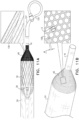
- the pump-outlet tube (or a different type of pump inlet guard) includes a coupling portion (e.g., a tubular coupling portion, as shown), which extends distally from the pump-outlet tube.
- the coupling portion is coupled a surface that is distal to the frame in order to anchor the distal end of the pump-outlet tube.
- the coupling portion defines a hole (e.g., toward the distal end of the coupling portion).
- adhesive is applied between the coupling portion and the surface, via the hole.
- the surface of is threaded. Typically, the threaded surface allows the adhesive to gradually and uniformly spread between the coupling portion and the surface.
- the coupling portion is transparent, such that the spread of the adhesive is visible through the coupling portion. Therefore, for some applications, once the adhesive has sufficiently spread between the coupling portion and the surface (e.g., once the surface has been covered with the adhesive), application of the adhesive is terminated.
- the ventricular assist device including a protective braid at a distal end thereof.
- a protective braid at a distal end thereof.
- the distal conical portion of the frame is covered (internally or externally) with the protective braid.
- the braid is embedded between the pump-outlet tube and the inner lining, such that, during crimping of the frame, the braid becomes crimped with the pump-outlet tube and the inner lining, thereby preventing the braid from moving with respect to pump-outlet tube and/or the inner lining.
- proximal and related terms when used with reference to a device or a portion thereof, should be interpreted to mean an end of the device or the portion thereof that, when inserted into a subject's body, is typically closer to a location through which the device is inserted into the subject's body.
- distal when used with reference to a device or a portion thereof, should be interpreted to mean an end of the device or the portion thereof that, when inserted into a subject's body, is typically further from the location through which the device is inserted into the subject's body.
- the scope of the present disclosure includes using the apparatus and methods described herein in anatomical locations other than the left ventricle and the aorta. Therefore, the ventricular assist device and/or portions thereof are sometimes referred to herein (in the specification and the claims) as a blood pump.
- an apparatus including: a left-ventricular assist device including:
- each of the blood-inlet openings is shaped such that, in at least one direction, a width of the opening is less than 1 mm.
- a ratio of the porosity of the distal portion of the pump-outlet tube within the distal region to the porosity of the distal portion of the pump-outlet tube within the proximal region is more than 4:3.
- the porosity of the distal portion of the pump-outlet tube is varied between the proximal region and the distal region such as to account for varying blood flow dynamics at different regions of the distal portion of the pump-outlet tube.
- the distal portion of the pump-outlet tube is conical, and the porosity of the distal portion of the pump-outlet tube is varied between the proximal region and the distal region such as to account for changes in the shape of the distal conical portion along its length.
- the pump-outlet tube defines large blood-inlet openings that are configured to reduce a risk of thrombosis relative to if the blood-inlet openings along the distal region of the distal conical portion of the pump-outlet tube were smaller.
- the distal portion of the pump-outlet tube defines more than 50 blood-inlet openings that are sized such as (a) to allow blood to flow from the subject's left ventricle into the tube and (b) to block structures from the subject's left ventricle from entering into the frame.
- the blood-inlet openings are rectangular and are shaped such that a ratio of lengths to widths of each of the blood-inlet openings is between 1.1:1 and 4:1. In some applications, the blood inlet openings are rectangular and are shaped such that a ratio of lengths to widths of each of the blood-inlet openings is between 3:2 and 5:2.
- the distal portion of the pump-outlet tube has a porosity of more than 40 percent. In some applications, the distal portion of the pump-outlet tube has a porosity of more than 50 percent. In some applications, the distal portion of the pump-outlet tube has a porosity of more than 60 percent.
- the frame defines a central cylindrical portion and a distal conical portion
- the distal portion of the pump-outlet tube which defines the blood-inlet openings, is conical and is disposed over the distal conical portion of the frame, and a portion of the pump-outlet tube that is proximal to the distal portion of the pump-outlet tube is coupled to the central cylindrical portion of the frame.
- the portion of the pump-outlet tube that is proximal to the distal portion of the pump-outlet tube is coupled to the central cylindrical portion of the frame via heating, and the porosity is lower is within the proximal region of the distal portion of the pump-outlet tube, such that damage that may be caused to a material that defines the blood-inlet holes within the proximal region of the distal portion of the pump-outlet tube is reduced during the heating relative to if the porosity within the proximal region of the distal portion of the pump-outlet tube was higher.
- the apparatus further includes an inner lining coupled to an inner surface of the central cylindrical portion of the frame, such that the inner lining provides the central cylindrical portion of the frame with a smooth inner surface.
- the proximal region of the distal portion of the pump-outlet tube extends along a length of 0.5 - 2 mm.
- the blood-inlet openings have polygonal shapes. In some applications, the blood-inlet openings have hexagonal shapes.
- a diameter of a circle enclosed by each of the blood-inlet openings is between 0.1 and 0.6 mm. In some applications, within the proximal region of the distal portion of the pump-outlet tube, widths of gaps between adjacent blood-inlet openings are between 0.05 and 0.2 mm.
- a diameter of a circle enclosed by each of the blood-inlet openings is between 0.2 and 0.8 mm. In some applications, within the distal region of the distal portion of the pump-outlet tube, widths of gaps between adjacent blood-inlet openings are between 0.01 mm and 0.1 mm.
- a ratio of a diameter of a circle enclosed by each the blood-inlet openings with the distal region of the distal portion of the pump-outlet tube to a diameter of a circle enclosed by each of the blood-inlet openings with the proximal region of the distal portion of the pump-outlet tube is greater than 7:6. In some applications, a ratio of widths of gaps between adjacent blood-inlet openings with the proximal region of the proximal portion of the pump-outlet tube to widths of gaps between adjacent blood-inlet openings within the distal region of the distal portion of the pump-outlet tube is greater than 3:2.
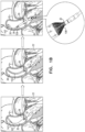
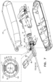
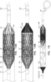
- FIGs. 1A , 1B , and 1C are schematic illustrations of a ventricular assist device 20, a distal end of which is configured to be disposed in a subject's left ventricle 22.
- Fig. 1A shows an overview of the ventricular assist device system including a control console 21, and a motor unit 23
- Fig. 1B shows the ventricular assist device being inserted into the subject's left ventricle
- Fig. 1C shows a pump-head portion 27 of the ventricular assist device in greater detail.
- the ventricular assist device includes a pump-outlet tube 24, which traverses an aortic valve 26 of the subject, such that a proximal end 28 of the pump-outlet tube is disposed in an aorta 30 of the subject and a distal end 32 of the pump-outlet tube is disposed within left ventricle 22.
- Pump-outlet tube 24 (which is sometimes referred to herein as a "blood-pump tube”) is typically an elongate tube, an axial length of the pump-outlet tube typically being substantially larger than its diameter.
- the scope of the present disclosure includes using the apparatus and methods described herein in anatomical locations other than the left ventricle and the aorta. Therefore, the ventricular assist device and/or portions thereof are sometimes referred to herein (in the specification and the claims) as a blood pump.
- the ventricular assist device is used to assist the functioning of a subject's left ventricle during a percutaneous coronary intervention.
- the ventricular assist device is typically used for a period of up to six hours (e.g., up to ten hours), during a period in which there is risk of developing hemodynamic instability (e.g., during or immediately following the percutaneous coronary intervention).
- the ventricular assist device is used to assist the functioning of a subject's left ventricle for a longer period (e.g., for example, 2-20 days, e.g., 4-14 days) upon a patient suffering from cardiogenic shock, which may include any low-cardiac-output state (e.g., acute myocardial infarction, myocarditis, cardiomyopathy, post-partum, etc.).
- cardiogenic shock which may include any low-cardiac-output state (e.g., acute myocardial infarction, myocarditis, cardiomyopathy, post-partum, etc.).
- the ventricular assist device is used to assist the functioning of a subject's left ventricle for yet a longer period (e.g., several weeks or months), e.g., in a "bridge to recovery" treatment.
- the ventricular assist device is permanently or semi-permanently implanted, and the impeller of the ventricular assist device is powered transcutaneously, e.g.,
- Fig. 1B which shows steps in the deployment of the ventricular assist device in the left ventricle
- the distal end of the ventricular assist device is guided to the left ventricle over a guidewire 10.
- a delivery catheter 143 is disposed over the distal end of the device.
- the delivery catheter is typically retracted to the aorta, and the guidewire is withdrawn from the subject's body. The retraction of the delivery catheter typically causes self-expandable components of the distal end of the device to assume non-radially-constrained configurations, as described in further detail hereinbelow.
- the ventricular assist device is inserted into the subject's body in order to provide an acute treatment to the subject.
- the delivery catheter is advanced over the distal end of the device, which causes the self-expandable components of the distal end of the device to assume radially-constrained configurations.
- the distal end of the device is retracted into the delivery catheter which causes the self-expandable components of the distal end of the device to assume radially-constrained configurations.
- the ventricular assist device and/or delivery catheter 143 includes an ultrasound transducer at its distal end and the ventricular assist device is advanced toward the subject's ventricle under ultrasound guidance.
- Fig. 1C shows pump-head portion 27 of ventricular assist device 20, in greater detail.
- an impeller 50 is disposed within a distal portion 102 of pump-outlet tube 24 and is configured to pump blood from the left ventricle into the aorta by rotating.
- the pump-outlet tube typically defines one or more blood-inlet openings 108 at the distal end of the pump-outlet tube, via which blood flows into the pump-outlet tube from the left ventricle, during operation of the impeller.
- the pump-outlet tube defines a single axially-facing blood-inlet opening.
- the pump-outlet tube defines a plurality of lateral blood-inlet openings (e.g., as shown in Fig. 1B ), as described in further detail hereinbelow.
- proximal portion 106 of the pump-outlet tube defines one or more blood-outlet openings 109, via which blood flows from the pump-outlet tube into the ascending aorta, during operation of the impeller.
- control console 21 (shown in Fig. 1A ), which typically includes a computer processor 25, drives the impeller to rotate.
- the computer processor may control a motor 74 (shown in Fig. 7 ), which is disposed within motor unit 23 (shown in Fig. 1A ) and which drives the impeller to rotate via a drive cable 130 (shown in Fig. 7 ).
- the computer processor is configured to detect a physiological parameter of the subject (such as left-ventricular pressure, cardiac afterload, rate of change of left-ventricular pressure, etc.) and to control rotation of the impeller in response thereto, as described in further detail hereinbelow.
- Computer processor 25 is typically a hardware device programmed with computer program instructions to produce a special-purpose computer.
- computer processor 25 when programmed to perform the techniques described herein, computer processor 25 typically acts as a special-purpose, ventricular-assist computer processor and/or a special-purpose, blood-pump computer processor.
- a purging system 29 (shown in Fig. 1A ) drives a fluid (e.g., a glucose solution) to pass through portions of ventricular assist device 20, for example, in order to cool portions of the device, to purge and/or lubricate interfaces between rotating parts and stationary bearings, and/or in order to wash debris from portions of the device.
- a fluid e.g., a glucose solution
- a frame 34 is disposed within the pump-outlet tube around impeller 50.
- the frame is typically made of a shape-memory alloy, such as nitinol.
- the shape-memory alloy of the frame is shape set such that at least a portion of the frame (and thereby distal portion 102 of tube 24) assumes a generally circular, elliptical, or polygonal cross-sectional shape in the absence of any forces being applied to distal portion 102 of tube 24.
- the frame is configured to hold the distal portion of the pump-outlet tube in an open state.
- the distal portion of the pump-outlet tube is configured to be placed within the subject's body, such that the distal portion of the pump-outlet tube is disposed at least partially within the left ventricle.
- Pump-outlet tube 24 is typically made of a blood-impermeable collapsible material.
- pump-outlet tube 24 may include polyurethane, polyester, and/or silicone.
- the pump-outlet tube is made of polyethylene terephthalate (PET) and/or polyether block amide (e.g., PEBAX ® ).
- the pump-outlet tube is reinforced with a reinforcement structure, e.g., a braided reinforcement structure, such as a braided nitinol tube.
- a reinforcement structure e.g., a braided reinforcement structure, such as a braided nitinol tube.
- the proximal portion of the pump-outlet tube is configured to be placed such that it is at least partially disposed within the subject's ascending aorta.
- the proximal portion of the pump-outlet tube traverses the subject's aortic valve, passing from the subject's left ventricle into the subject's ascending aorta, as shown in Fig. 1B .
- the pump-outlet tube typically defines one or more blood-inlet openings 108 at the distal end of the pump-outlet tube, via which blood flows into the pump-outlet tube from the left ventricle, during operation of the impeller.
- the proximal portion of the pump-outlet tube defines one or more blood-outlet openings 109, via which blood flows from the pump-outlet tube into the ascending aorta, during operation of the impeller.
- the pump-outlet tube defines a plurality of blood-outlet openings 109, for example, between two and eight blood-outlet openings (e.g., between two and four blood-outlet openings).
- the pressure of the blood flow through the pump-outlet tube typically maintains the proximal portion of the tube in an open state.
- the proximal portion of the pump-outlet tube is configured to collapse inwardly, in response to pressure outside of the proximal portion of the pump-outlet tube exceeding pressure inside the proximal portion of the pump-outlet tube. In this manner, the proximal portion of the pump-outlet tube acts as a safety valve, preventing retrograde blood flow into the left ventricle from the aorta.
- frame 34 is shaped such that the frame defines a proximal conical portion 36, a central cylindrical portion 38, and a distal conical portion 40.
- the proximal conical portion is proximally-facing, i.e., facing such that the narrow end of the cone is proximal with respect to the wide end of the cone.
- the distal conical portion is distally-facing, i.e., facing such that the narrow end of the cone is distal with respect to the wide end of the cone.
- pump-outlet tube 24 extends to the end of cylindrical portion 38 (or slightly proximal or distal thereof), such that the distal end of the pump-outlet tube defines a single axially-facing blood-inlet opening 108, as shown in Fig. 1C .
- an inner lining 39 lines the frame.
- Fig. 1C shows an arrangement of the pump-head portion without inner lining 39, but several figures (e.g., Figs.
- FIGS. 4 , 5A , 6A-6B , 9A-9B , 10A-10C , 11A , 11C , 13A , and 14A-C) show arrangements of a pump-head portion that includes inner lining 39.
- the inner lining partially overlaps or fully overlaps with pump-outlet tube 24 over the portion of the frame that the inner lining lines, as described in further detail hereinbelow with reference to Figs. 9A-B .
- pump-outlet tube 24 includes a conical proximal portion 42 and a cylindrical central portion 44.
- the proximal conical portion is typically proximally-facing, i.e., facing such that the narrow end of the cone is proximal with respect to the wide end of the cone.
- blood-outlet openings 109 are defined by pump-outlet tube 24, such that the openings extend at least partially along the proximal conical section of tube 24.
- the blood-outlet openings are teardrop-shaped, as shown in Fig. 1C .
- the teardrop-shaped nature of the blood-outlet openings in combination with the openings extending at least partially along the proximal conical section of tube 24 causes blood to flow out of the blood-outlet openings along flow lines that are substantially parallel with the longitudinal axis of tube 24 at the location of the blood-outlet openings.
- the diameter of pump-outlet tube 24 changes along the length of the central portion of the pump-outlet tube, such that the central portion of the pump-outlet tube has a frustoconical shape.
- the central portion of the pump-outlet tube may widen from its proximal end to is distal end, or may narrow from its proximal end to its distal end.
- the central portion of the pump-outlet tube has a diameter of between 5 and 7mm, and at its distal end, the central portion of the pump-outlet tube has a diameter of between 8 and 12 mm.
- the ventricular assist device typically includes a distal-tip element 107 that is disposed distally with respect to frame 34 and that includes an axial-shaft-receiving tube 126 and a distal-tip portion 120.
- the axial-shaft receiving tube is configured to receive a distal portion of an axial shaft 92 of the pump-head portion during axial back-and-forth motion of the axial shaft (as described in further detail hereinbelow), and/or during delivery of the ventricular assist device.
- distal-tip portion 120 is configured to assume a curved shape upon being deployed within the subject's left ventricle, e.g., as shown in Fig. 1C .
- the curvature of the distal-tip portion is configured to provide an atraumatic tip to ventricular assist device 20.
- the distal-tip portion is configured to space blood-inlet openings 108 of the ventricular assist device from walls of the left ventricle.
- pump-outlet tube 24 extends to the end of distal conical portion 40 of the frame, and the pump-outlet tube defines a plurality of lateral blood-inlet openings 108, as described in further detail hereinbelow.
- the pump-outlet tube typically defines a distal conical portion that is distally facing, i.e., such that the narrow end of the cone is distal with respect to the wide end of the cone.
- the pump-outlet tube defines two to four lateral blood-inlet openings (e.g., four lateral blood-inlet openings, as shown).
- each of the blood-inlet openings defines an area of more than 20 square mm (e.g., more than 30 square mm), and/or less than 60 square mm (e.g., less than 50 square mm), e.g., 20-60 square mm, or 30-50 square mm.
- the outlet tube defines a greater number of smaller lateral blood-inlet openings, e.g., more than 10 blood-inlet openings, more than 50 blood-inlet openings, more than 200 blood-inlet openings, or more than 400 blood-inlet openings, e.g., 50-100 blood-inlet openings, 100-400 blood-inlet openings, or 400-600 blood-inlet openings.
- each of the blood-inlet openings defines an area of more than 0.05 square mm (e.g., more than 0.1 square mm), and/or less than 3 square mm (e.g., less than 1 square mm), e.g., 0.05-3 square mm, or 0.1-1 square mm.
- each of the blood-inlet openings defines an area of more than 0.1 square mm (e.g., more than 0.3 square mm), and/or less than 5 square mm (e.g., less than 1 square mm), e.g., 0.1-5 square mm, or 0.3-1 square mm.
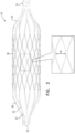
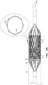
- FIG. 2 is schematic illustration of frame 34 that houses an impeller of ventricular assist device 20.
- Frame 34 is typically made of a shape-memory alloy, such as nitinol, and the shape-memory alloy of the frame is shape set such that the central portion of the frame (and thereby tube 24) assumes a generally circular, elliptical, or polygonal cross-sectional shape in the absence of any forces being applied to pump-outlet tube 24.
- the frame is configured to hold the distal portion of the tube in an open state.
- the frame is a stent-like frame, in that it comprises struts that, in turn, define cells. Further typically, the frame is covered with pump-outlet tube 24, and/or covered with an inner lining 39, described hereinbelow, with reference to Figs. 9A-B . As described hereinbelow, for some applications impeller 50 undergoes axial back-and-forth motion with respect to frame 34. Typically, over the course of the motion of the impeller with respect to the frame the location of the portion of the impeller that defines the maximum span of the impeller is disposed within central cylindrical portion 38 of frame 34.
- pump-outlet tube 24, and/or inner lining 39 gets stretched between edges of the cells, such that the pump-outlet tube 24, and/or inner lining 39 does not define a circular cross-section.
- this occurs in the region in which the portion of the impeller that defines the maximum span of the impeller is disposed, this results in a non-constant gap between the edges of the impeller blades and tube 24 (and/or inner lining) at that location, over the course of a rotation cycle of the impeller.
- this may lead to increased hemolysis relative to if there were a constant gap between the edges of the impeller blades and tube 24 (and/or inner lining) at that location, over the course of the rotation cycle of the impeller.
- the frame defines a large number of relatively small cells.
- the maximum cell width CW of the each of the cells i.e., the distance from the inner edge of the strut at the central junction on one side of the cell to the inner edge of the strut at the central junction on the other side of the cell, as measured around the circumference of cylindrical portion 38
- inner lining 39 defines a substantially circular cross-section within the cylindrical portion of the frame.
- the frame defines the following portions (a) coupling portion 31 via which the frame is coupled to a distal bearing housing 118H (shown in Fig. 5A ) of the ventricular assist device, (b) distal conical portion 40, (c) central cylindrical portion 38, (d) proximal conical portion 36, and (e) proximal strut junctions 33.
- struts 37 of the frame pass through junctions 35, at which the two struts branch from a single strut, in a Y-shape.
- typically frame 34 is placed in a radially-constrained (i.e., crimped) configuration within delivery catheter 143 by the frame being axially elongated.
- the frame typically transmits its radial narrowing to the impeller, and the impeller becomes radially constrained by becoming axially elongated within the frame.
- the struts of the frame being configured in the manner described above facilitates transmission of axial elongation from the delivery catheter (or other device that is configured to crimp the frame) to the frame, which in turn facilitates transmission of axial elongation to the impeller. This is because the pairs of struts that branch from each of junctions 35 are configured to pivot about the junction and move closer to each other such as to close.
- distal coupling portion 31 is coupled to a distal bearing housing 118H (shown in Fig. 5A ), e.g., via a snap-fit mechanism.
- proximal strut junctions 33 are still maintained in open states at this stage, in order for the impeller to be placed within the frame via the proximal end of the frame.
- the structure of frame 34 shown in Fig. 2 is used in applications in which pump-outlet tube extends to the distal end of frame 34 (e.g., as shown in Fig. 1B ).
- the impeller cannot be inserted via the distal end of the frame, since the distal end of the frame is covered by pump-outlet tube 24.
- the proximal strut junctions are closed.
- the proximal strut junctions are closed around the outside of a proximal bearing housing 116H (shown in Fig. 5A ), as described in further detail hereinbelow with reference to Figs. 5A-B .
- a securing element 117 e.g., a ring shown in Fig. 5A ) holds the strut junctions in their closed configurations around the outside of proximal bearing housing 116H.
- frame 34 when disposed in its non-radially constrained configuration, has a total length of more than 25 mm (e.g., more than 30 mm), and/or less than 50 mm (e.g., less than 45 mm), e.g., 25-50 mm, or 30-45 mm.
- the length of the frame increases by between 2 and 5 mm.
- the central cylindrical portion of frame 34 when disposed in its non-radially constrained configuration, has a length of more than 10 mm (e.g., more than 12 mm), and/or less than 25 mm (e.g., less than 20 mm), e.g., 10-25 mm, or 12-20 mm.
- a ratio of the length of the central cylindrical portion of the frame to the total length of the frame is more than 1:4 and/or less than 1:2, e.g., between 1:4 and 1:2.
- the impeller includes at least one outer helical elongate element 52, which winds around a central axial spring 54, such that the helix defined by the helical elongate element is coaxial with the central axial spring.
- the impeller includes two or more helical elongate elements (e.g., three helical elongate elements, as shown in Figs. 3A-C ).
- the helical elongate elements and the central axial spring are made of a shape-memory material, e.g., a shape-memory alloy, such as nitinol.
- each of the helical elongate elements and the central axial spring support a film 56 of a material (e.g., an elastomer, such as polyurethane, and/or silicone) therebetween.
- the film of material includes pieces of nitinol embedded therein, for example in order to strengthen the film of material.
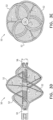
- the impeller is shown in the absence of the material in Fig. 3A.
- Figs. 3B and 3C show respective views of the impeller with the material supported between the helical elongate elements and the spring.
- Figs. 3D and 3E show similar respective views of the impeller to those shown in Figs. 3B and 3C , but with certain features of the impeller differing from those shown in Figs. 3B and 3C , as elaborated upon hereinbelow.
- Each of the helical elongate elements together with the film extending from the helical elongate element to the spring, defines a respective impeller blade, with the helical elongate elements defining the outer edges of the blades, and the axial spring defining the axis of the impeller.
- the film of material extends along and coats the spring.
- sutures 53 e.g., polyester sutures, shown in Figs. 3A-C
- sutures 53 are wound around the helical elongate elements.
- the sutures are configured to facilitate bonding between the film of material (which is typically an elastomer, such as polyurethane, or silicone) and the helical elongate element (which is typically a shape-memory alloy, such as nitinol).
- sutures e.g., polyester sutures, not shown
- the sutures are configured to facilitate bonding between the film of material (which is typically an elastomer, such as polyurethane, or silicone) and the spring (which is typically a shape-memory alloy, such as nitinol).
- the helical elongate elements typically rise gradually from the proximal bushing before reaching a maximum span and then falling gradually toward the distal bushing.
- the helical elongate elements are symmetrical along their lengths, such that the rising portions of their lengths are symmetrical with respect to the falling portions of their lengths.
- the impeller defines a lumen 62 therethrough (shown in Fig. 3C ), with the lumen typically extending through, and being defined by, spring 54, as well as proximal bushing 64 and distal bushing 58, of the impeller.
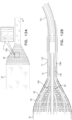
- Fig. 4 is a schematic illustration of impeller 50 disposed inside frame 34 of ventricular assist device 20.
- inner lining 39 lines the frame.
- the inner lining partially overlaps or fully overlaps with pump-outlet tube 24 over the portion of the frame that the inner lining lines , as described in further detail hereinbelow with reference to Figs. 9A-B .
- a gap G typically there is a gap G, between the outer edge of impeller 50 and inner lining 39, even at a location at which the span of the impeller is at its maximum.
- gap G between the outer edge of the impeller and the inner lining 39, at the location at which the span of the impeller is at its maximum is greater than 0.05 mm (e.g., greater than 0.1 mm), and/or less than 1 mm (e.g., less than 0.4 mm), e.g., 0.05-1 mm, or 0.1-0.4 mm.
- the outer diameter of the impeller at the location at which the outer diameter of the impeller is at its maximum is more than 7 mm (e.g., more than 8 mm), and/or less than 10 mm (e.g., less than 9 mm), e.g., 7-10 mm, or 8-9 mm.
- the inner diameter of frame 34 (as measured from the inside of inner lining 39 on one side of the frame to the inside of inner lining on the opposite side of the frame) is greater than 7.5 mm (e.g., greater than 8.5 mm), and/or less than 10.5 mm (e.g., less than 9.5 mm), e.g., 7.5-10.5 mm, or 8.5-9.5 mm.
- the outer diameter of frame 34 is greater than 8 mm (e.g., greater than 9 mm), and/or less than 13 mm (e.g., less than 12 mm), e.g., 8-13 mm, or 9-12 mm.
- an axial shaft 92 passes through the axis of impeller 50, via lumen 62 of the impeller.
- the axial shaft is rigid, e.g., a rigid tube.
- proximal bushing 64 of the impeller is coupled to the shaft such that the axial position of the proximal bushing with respect to the shaft is fixed, and distal bushing 58 of the impeller is slidable with respect to the shaft.
- the proximal bushing may be coupled to a coupling element 65 disposed on the axial shaft (shown in Fig. 4 ), for example via a snap-fit mechanism.
- distal bushing 58 of the impeller is coupled to the shaft such that the axial position of the distal bushing with respect to the shaft is fixed, and proximal bushing 64 of the impeller is slidable with respect to the shaft.
- the axial shaft itself is radially stabilized via a proximal radial bearing 116 and a distal radial bearing 118.
- the axial shaft by passing through lumen 62 defined by the impeller, radially stabilizes the impeller with respect to the inner surface of frame 34, such that even a relatively small gap between the outer edge of the blade of the impeller and the inner surface of frame 34 (e.g., a gap that is as described above) is maintained, during rotation of the impeller.
- the impeller includes a plurality of elongate elements 67 extending radially from central axial spring 54 to outer helical elongate elements 52.
- the elongate elements are typically flexible but are substantially non-stretchable along the axis defined by the elongate elements.
- each of the elongate elements is configured not to exert force upon the helical elongate element, unless force is acting upon the impeller that is causing the helical elongate element to move radially outward, such that (in the absence of the elongate element) a separation between the helical elongate element and the central axial spring would be greater than a length of the elongate element.
- the elongate elements may include strings (such as polyester, and/or another polymer or a natural material that contains fibers) and/or wires (such as nitinol wires, and/or wires made of a different alloy, or a metal).
- the elongate elements 67 maintain helical elongate element 52 (which defines the outer edge of the impeller blade) within a given distance with respect to the central axial spring.
- the elongate elements are configured to prevent the outer edge of the impeller from being forced radially outward due to forces exerted upon the impeller during the rotation of the impeller.
- the elongate elements are thereby configured to maintain the gap between the outer edge of the blade of the impeller and the inner surface of frame 34, during rotation of the impeller.
- Figs. 3D and 3E are schematic illustrations of impeller 50, the impeller including a single integrated impeller-overexpansion-prevention element 72 that defines a plurality of elongate elements 67.
- impeller-overexpansion-prevention element 72 (which defines a plurality of elongate elements 67) is used as an alternative to elongate elements 67 as shown in Figs. 3A-C .
- element 72 defines a ring 73 and the plurality of elongate elements 67 extending radially from the ring.
- ring 73 of element 72 is placed around the spring, e.g., by being placed around tube 70, which is typically disposed at the longitudinally-central location of the spring.
- the ends of respective elongate elements 67 are then coupled to respective helical elongate elements 52.
- elongate elements 67 are typically flexible but are substantially non-stretchable along the axis defined by the elongate elements. Further typically, each of elongate elements 67 is configured to substantially not resist compression.
- each elongate element 67 is configured to exert a tensile force upon helical elongate element 52 that prevents helical elongate element 52 from moving radially outward, such that (in the absence of elongate element 67) a separation between helical elongate element 52 and central axial spring 54 would be greater than a length of elongate element 67.
- the impeller-overexpansion-prevention element is configured to prevent radial expansion of the impeller.
- a respective elongate element 67 is disposed within each one of the impeller blades and is configured to prevent the impeller blade from radially expanding.
- element 72 is made of polyester, and/or another polymer or a natural material that contains fibers, and/or nitinol (or a similar shape-memory alloy).
- the scope of the present application includes using single integrated impeller-overexpansion-prevention element 72 with an impeller having a different construction from that shown in Figs. 3D-E .
- the single integrated impeller-overexpansion-prevention element 72 could be used with an impeller having a differently constructed axial structure than spring 54.
- the axial structure defines a lumen therethrough, such that the impeller defines lumen 62 therethrough.
- the following assembly technique is used to manufacture the impeller while enhancing bonding of an elastomeric material that is used to form film 56 to the at least one helical elongate element.
- bonding of the elastomeric material to the at least one helical elongate element is performed in a manner that does not cause a protrusion from the effective edge of the impeller blade.
- bonding of the elastomeric material to the at least one helical elongate element is performed in a manner that provides the impeller blade with a rounded outer edge, by the elastomeric material rounding edges of the helical elongate element.
- Proximal bushing 64, distal bushing 58, and helical elongate elements 52 are cut from a tube of shape-memory material, such as nitinol.
- the cutting of the tube, as well as the shape setting of the shape-memory material, is typically performed such that the helical elongate elements and the bushings are defined by a tube of shape-memory material that is cut and shape set.
- a plasma treatment is applied to the helical elongate elements prior to being coupled to spring 54.
- the helical elongate elements are coated with a coupling agent.
- a coupling agent is selected that has at least two functional groups that are configured to bond respectively with the helical elongate elements and with the elastomeric material.
- a silane compound such as n-(2-aminoethyl)-3-aminopropyltrimethoxysilane, may be used, with the silane compound containing a first functional group (e.g., (OH)) which is configured to bond with the helical elongate elements (which are typically made of an alloy, such a nitinol), and the silane compound containing a second functional group (e.g., (NH2)) which is configured to bond with the elastomeric material.
- a first functional group e.g., (OH)
- a second functional group e.g., (NH2)
- the functional groups in the coupling agent are only active for a given time period (e.g., approximately an hour or less). Therefore, during this time period, a coat of elastomeric material is applied around the helical elongate elements.
- the coat of elastomeric material is the same elastomeric material or a similar elastomeric material to that used in film 56.
- a polycarbonate-based thermoplastic polyurethane such as Aromatic Carbothane TM (e.g., Aromatic Carbothane TM 75A) may be used in film 56, and the coating may be the same polycarbonate-based thermoplastic polyurethane, or a similar polycarbonate-based thermoplastic polyurethane, such as Pellethane ® (e.g., Pellethane ® 90A).
- Aromatic Carbothane TM e.g., Aromatic Carbothane TM 75A
- Pellethane ® e.g., Pellethane ® 90A
- proximal bushing 64, distal bushing 58, and helical elongate elements 52 are typically cut from a tube of shape-memory material, such as nitinol.
- shape-memory material such as nitinol.
- spring 54 is coupled to the helical elongate elements.
- spring 54 is inserted into the cut and shape-set tube, such that the spring extends along the length of the tube from at least the proximal bushing to the distal bushing.
- the spring is inserted into the cut and shape-set tube while the spring is in an axially compressed state, and the spring is configured to be held in position with respect to the tube, by exerting a radial force upon the proximal and distal bushings.
- portions of the spring are welded to the proximal and distal bushings.
- the spring is cut from a tube of a shape-memory material, such as nitinol.
- the spring is configured such that, when the spring is disposed in a non-radially-constrained configuration (in which the spring is typically disposed during operation of the impeller), there are substantially no gaps between windings of the spring and adjacent windings thereto.
- overexpansion-prevention element 72 is placed between the spring and the helical elongate elements, as described hereinabove, such that an assembly is formed that includes coated helical elongate elements 52, spring 54, and overexpansion-prevention element 72.
- the assembly of coated helical elongate elements 52, spring 54, and overexpansion-prevention element 72 is sprayed with a further layer of an elastomeric material.
- the elastomeric material that is sprayed is the same elastomeric material or a similar elastomeric material to that used as film 56.
- a polycarbonate-based thermoplastic polyurethane such as Aromatic Carbothane TM (e.g., Aromatic Carbothane TM 75A) may be used as film 56, and the sprayed material may be the same polycarbonate-based thermoplastic polyurethane, or a similar polycarbonate-based thermoplastic polyurethane, such as Pellethane ® (e.g., Pellethane ® 90A).
- applying the spray to the helical elongate elements rounds the helical elongate elements.
- the helical elongate element has a rounded cross section
- the elastomeric material forms a layer having a substantially uniform thickness at the interface with the helical elongate element.
- the assembly of coated helical elongate elements 52, spring 54, and overexpansion-prevention element 72 is dipped in the elastomer from which film 56 is made.
- the material from which the film is made is an elastomer having an ultimate elongation of more than 300 percent, e.g., more than 400 percent.
- the material has a relatively low molecular weight.
- the material has a melt flow index (which is an indirect measure of molecular weight) of at least 4, e.g., at least 4.3.
- the material has an ultimate tensile strength of more than 4.1 x 10 7 Pa (6000 psi), e.g., more than 4.8 x 10 7 Pa (7000 psi), or more than 5.2 x 10 7 Pa (7500 psi).
- the material is a polycarbonate-based thermoplastic polyurethane, e.g., a Carbothane TM .
- Aromatic Carbothane TM e.g., Aromatic Carbothane TM 75A
- such materials combine one or more of the following properties: no outer diameter loss caused during the dip process, resistance to fatigue, resistance to becoming misshaped by being crimped, and low outer diameter loss during crimping.
- the material is cured such that it solidifies, e.g., by being left to dry.
- the impeller is disposed on a mandrel, such that the mandrel passes through lumen 62 defined by the bushings and the spring, thereby maintaining the lumen during the drying.
- the impeller is rotated, which typically facilitates the formation of a film of material having a substantially uniform thickness within each of the impeller blades.
- the mandrel is typically removed from lumen 62.
- the scope of the present disclosure includes any technique whereby, prior to the helical elongate elements being dipped into the elastomeric material from which film 56 is made, additional layers of the same elastomeric material, a different elastomeric material, and/or a mediating material are applied to the helical elongate elements, whether by spraying, dipping, or a different coating method.
- additional layers of elastomeric material are configured to round the helical elongate elements, and/or to act as mediators to enhance bonding between the helical elongate elements and film 56 of material.
- a mediating material (such as silane) is configured to act as a mediator to enhance bonding between the helical elongate elements and film 56 of material.
- impeller 50 is inserted into the left ventricle transcatheterally, while impeller 50 is in a radially-constrained configuration.
- both helical elongate elements 52 and central axial spring 54 become axially elongated, and radially constrained.
- film 56 of the material e.g., silicone and/or polyurethane
- film 56 of the material changes shape to conform to the shape changes of the helical elongate elements and the axial support spring, both of which support the film of material.
- using a spring to support the inner edge of the film allows the film to change shape without the film becoming broken or collapsing, due to the spring providing a large surface area to which the inner edge of the film bonds.
- using a spring to support the inner edge of the film reduces a diameter to which the impeller can be radially constrained, relative to if, for example, a rigid shaft were to be used to support the inner edge of the film, since the diameter of the spring itself can be reduced by axially elongating the spring.
- proximal bushing 64 of impeller 50 is coupled to axial shaft 92 such that the axial position of the proximal bushing with respect to the shaft is fixed, and distal bushing 58 of the impeller is slidable with respect to the shaft.
- the proximal bushing may be coupled to coupling element 65 disposed on the axial shaft (shown in Fig. 4 ), for example via a snap-fit mechanism.
- the impeller when the impeller is radially constrained for the purpose of inserting the impeller into the ventricle or for the purpose of withdrawing the impeller from the subject's body, the impeller axially elongates by the distal bushing sliding along the axial shaft distally.
- distal bushing 58 of the impeller is coupled to the shaft such that the axial position of the distal bushing with respect to the shaft is fixed, and proximal bushing 64 of the impeller is slidable with respect to the shaft.
- the impeller when the impeller is radially constrained for the purpose of inserting the impeller into the ventricle or for the purpose of withdrawing the impeller from the subject's body, the impeller axially elongates by the proximal bushing sliding along the axial shaft proximally. Subsequent to being released inside the subject's body, the impeller assumes its non-radially-constrained configuration (in which the impeller is typically disposed during operation of the impeller), which is as shown in Figs. 3A-E .
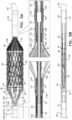
- Figs. 5A and 5B are schematic illustrations of impeller 50 and frame 34 of ventricular assist device 20, respectively in non-radially-constrained and radially-constrained states thereof.
- the impeller and the frame are typically disposed in the radially-constrained states during the transcatheteral insertion of the impeller and the frame into the subject's body, and are disposed in the non-radially-constrained states during operation of the impeller inside the subject's left ventricle.
- the frame and the impeller are typically maintained in radially-constrained configurations by delivery catheter 143.
- the impeller has a total length of more than 15 mm (e.g., more than 20 mm), and/or less than 30 mm (e.g., less than 25 mm), e.g., 15-30 mm, or 20-25 mm.
- the impeller has a length of more than 8 mm (e.g., more than 10 mm), and/or less than 18 mm (e.g., less than 15 mm), e.g., 8-18 mm, or 10-15 mm.
- the impeller and frame 34 are disposed in radially-constrained configurations (as shown in Fig. 5B ), the impeller has an outer diameter of less than 2 mm (e.g., less than 1.6 mm) and the frame has an outer diameter of less than 2.5 mm (e.g., less than 2.1 mm).
- axial shaft 92 passes through the axis of impeller 50, via lumen 62 of the impeller.
- proximal bushing 64 of the impeller is coupled to the shaft via a coupling element 65 such that the axial position of the proximal bushing with respect to the shaft is fixed, and distal bushing 58 of the impeller is slidable with respect to the shaft.
- distal bushing 58 of the impeller is coupled to the shaft such that the axial position of the distal bushing with respect to the shaft is fixed, and proximal bushing 64 of the impeller is slidable with respect to the shaft.
- the axial shaft itself is radially stabilized via a proximal radial bearing 116 and a distal radial bearing 118.
- proximal bearing housing 116H is disposed around, and houses, the proximal bearing
- distal bearing housing 118H is disposed around, and houses, the distal bearing.
- the radial bearings and the bearing housings are made of respective, different materials from each other.
- the radial bearings may be made of a first material that has a relatively high hardness, such as ceramic (e.g., zirconia), and the bearing housings may be made of a second material that is moldable into a desired shape, such as a metal or an alloy (e.g., stainless steel, cobalt chromium, and/or nitinol).
- a first material that has a relatively high hardness
- the bearing housings may be made of a second material that is moldable into a desired shape, such as a metal or an alloy (e.g., stainless steel, cobalt chromium, and/or nitinol).
- axial shaft 92 is made of a metal or an alloy, such as stainless steel.
- the axial shaft covered with ceramic sleeves 240 (e.g., zirconia sleeves) along regions of the axial shaft that come into contact with either of the proximal and distal bearings 116, 118 during operation of the ventricular assist device.
- the radial interfaces between the axial shaft and the proximal and distal bearings is a ceramic-ceramic interface.
- the impeller and the axial shaft are configured to undergo axial back-and-forth motion during operation of the ventricular assist device.
- the axial shaft is covered with the ceramic sleeve along a length of more than 5 mm, e.g., more than 7 mm. In this manner, over the course of the axial back-and-forth motion of the axial shaft, the regions of the axial shaft that are in contact with the radial bearings are covered with the ceramic sleeves.
- proximal bearing housing 116H and distal bearing housing 118H perform additional functions.
- proximal strut junctions 33 of frame 34 are closed around the outside of the proximal bearing housing.
- the outer surface of the proximal bearing housing defines groves that are shaped such as to receive the proximal strut junctions.
- the proximal strut junctions have widened heads, and the outer surface of the proximal bearing housing defines groves that are shaped to conform with the widened heads of the proximal strut junctions.
- securing element 117 (which typically includes a ring) holds the strut junctions in their closed configurations around the outside of proximal bearing housing 116H.
- additional portions of the ventricular assist device are coupled to the proximal bearing housing.
- a drive cable 130 extends from outside the subject's body to axial shaft 92, and is coupled to the axial shaft.
- the drive cable rotates within a first outer tube 140, which functions as a drive-cable bearing tube, and which extends from outside the subject's body to the proximal bearing housing.
- the first outer tube is disposed within a second outer tube 142, which also extends from outside the subject's body to the proximal bearing housing.
- first outer tube 140 and/or second outer tube 142 is coupled to the proximal bearing housing (e.g., using an adhesive).
- first outer tube 140 may be coupled to an inner surface of the proximal bearing housing
- second outer tube 142 may be coupled to an outer surface of the proximal bearing housing.
- distal coupling portion 31 of frame 34 is coupled to an outer surface of distal bearing housing 118H, e.g., via a snap-fit mechanism.
- the outer surface of a proximal-most portion 119 of the distal bearing housing may include a snap-fit mechanism to which distal coupling portion 31 of frame 34 is coupled.
- distal bearing 118 is disposed within the proximal-most portion 119 of the distal bearing housing, as shown in Fig. 5A .
- pump-outlet tube 24 extends to the distal end of frame 34 and defines lateral blood-inlet openings 108.
- a coupling portion 41 extends distally from the pump-outlet tube, and the coupling portion is coupled to the distal bearing housing in order to anchor the distal end of the pump-outlet tube.
- an intermediate portion 123 of the distal bearing housing defines a ridged or a threaded outer surface, to which coupling portion 41 of the pump-outlet tube is coupled (e.g., via adhesive).
- the outer surface is ridged in order to enhance bonding between the distal bearing housing and coupling portion 41 of the pump-outlet tube.
- a distal portion 121 of the distal bearing housing is configured to stiffen a region of distal-tip element 107 into which the distal end of shaft 92 moves (e.g., axial-shaft-receiving tube 126, or a portion thereof).
- distal-tip element 107 is coupled to an outer surface of distal portion 121 of the distal bearing housing (e.g., via adhesive).
- at least a portion of the outer surface of distal portion 121 of the distal bearing housing is ridged and/or threaded in order to enhance bonding between distal-tip element 107 and the distal bearing housing.
- axial shaft 92 is radially stabilized via proximal radial bearing 116 and distal radial bearing 118.
- the axial shaft by passing through lumen 62 defined by the impeller, radially stabilizes the impeller with respect to the inner surface of frame 34 and inner lining 39, such that even a relatively small gap between the outer edge of the blade of the impeller and inner lining 39 (e.g., a gap that is as described above) is maintained, during rotation of the impeller, as described hereinabove.
- the impeller itself is not directly disposed within any radial bearings or thrust bearings. Rather, bearings 116 and 118 act as radial bearings with respect to the axial shaft.
- pump-head portion 27 does not include any thrust bearing that is configured to be disposed within the subject's body and that is configured to oppose thrust generated by the rotation of the impeller.
- one or more thrust bearings are disposed outside the subject's body (e.g., within motor unit 23, shown in Figs. 1A , 7 , and 8A-B ), and opposition to thrust generated by the rotation of the impeller is provided solely by the one or more thrust bearings disposed outside the subject's body.
- a mechanical element and/or a magnetic element is configured to maintain the impeller within a given range of axial positions.
- a magnet e.g., magnet 82, described hereinbelow with reference to Fig. 7
- the proximal end of the drive cable e.g., outside the subject's body
- the proximal end of the drive cable may be configured to impart axial motion to the impeller, and/or to maintain the impeller within a given range of axial positions.
- Figs. 6A and 6B are schematic illustrations of ventricular assist device 20 at respective stages of a motion cycle of impeller 50 of the ventricular assist device with respect to frame 34 of the ventricular assist device.
- axial shaft 92 to which the impeller is fixated
- axial shaft 92 is driven to move the impeller axially back-and-forth within frame 34, by the axial shaft moving in an axial back-and-forth motion, as described in further detail hereinbelow with reference to Fig. 7 .
- the impeller and the axial shaft are configured to move axially back-and-forth within frame 34 in response to forces that are acting upon the impeller, and without requiring the axial shaft to be actively driven to move in the axial back-and-forth motion.
- the pressure difference between the left ventricle and the aorta varies from being approximately zero during ventricular systole (hereinafter "systole”) to a relatively large pressure difference (e.g., 50-70 mmHg) during ventricular diastole (hereinafter "diastole").
- the impeller is pushed distally with respect to frame 34 during diastole, relative to the location of the impeller with respect to frame 34 during systole.
- the impeller since the impeller is connected to the axial shaft, the axial shaft is moved forward.
- the impeller and, in turn, the axial shaft) move back to their systolic positions.
- Figs. 6A and 6B show the impeller and axial shaft disposed at respective positions within frame 34 during the above-described axial back-and-forth motion cycle.
- the portions of the axial shaft that are in contact with proximal bearing 116 and distal bearing 118 are constantly changing.
- the frictional force that is exerted upon the axial shaft by the bearings is spread over a larger area of the axial shaft than if the axial shaft were not to move relative to the bearings, thereby reducing wear upon the axial shaft, ceteris paribus.
- the axial shaft cleans the interface between the axial shaft and the bearings from any residues, such as blood residues.
- the proximal end of the impeller within the proximal conical section of frame 34.
- the distal end of the impeller is disposed at the distal end of the cylindrical section of frame 34.
- the distal end of the impeller is disposed proximal to the distal end of the cylindrical section of frame 34.
- the section of the impeller at which the span of the impeller is at its maximum is disposed within the cylindrical portion of the frame 34.
- a proximal portion of the impeller is typically disposed within the proximal conical section of the frame during at least a portion of the cardiac cycle.
- distal-tip element 107 is a single integrated element that includes both axial-shaft-receiving tube 126 and distal-tip portion 120.
- the axial-shaft receiving tube is configured to receive a distal portion of axial shaft 92 of the pump-head portion during axial back-and-forth motion of the axial shaft (as described in further detail hereinbelow), and/or during delivery of the ventricular assist device.
- distal-tip portion 120 is configured to be soft, such that the distal-tip portion is configured not to injure tissue of the subject, even if the distal-tip portion comes into contact with the tissue (e.g., tissue of the left ventricle).
- distal-tip portion 120 or the entire distal-tip element may be made of silicone, polyethylene terephthalate (PET) and/or polyether block amide (e.g., PEBAX ® ).
- the distal-tip portion defines a lumen 122 therethrough.
- guidewire 10 Fig. 1B
- the distal-tip portion of the ventricular assist device is then guided to the left ventricle by advancing the distal-tip portion over the guidewire, with the guidewire disposed inside lumen 122.
- a duckbill valve 390 (or a different type of hemostasis valve) is disposed at the distal end of lumen 122 of distal-tip portion 120.
- delivery catheter 143 is placed over impeller 50 and frame 34 and maintains the impeller and the frame in their radially-constrained configurations.
- distal-tip element 107 extends distally from the delivery catheter during the insertion of the delivery catheter into the subject's ventricle, as shown in Fig. 1B .
- the distal-tip element has a protrusion 110. Referring to Fig.
- the delivery catheter extends until the proximal side of the protrusion, such that the delivery catheter and the protrusion form a smooth continuous surface.
- the distal side of protrusion 110 is tapered, such that the vasculature is exposed to a tapered diameter change, and is not exposed to any edges arising from a sharp change in diameter at the interface between the delivery catheter and the distal-tip element.
- distal-tip element 107 defines an overall curvature that is similar to that of a question mark or a tennis-racket, with the distal-tip element defining a straight proximal portion and a bulge on one side of the longitudinal axis of the straight proximal portion.
- the ventricular assist device is introduced into the subject's ventricle over a guidewire, as described hereinabove.
- Distal-tip portion 120 defines lumen 122, such that the distal-tip portion is held in a straightened configuration during the introduction of the ventricular assist device into the subject's ventricle (e.g., as shown in the left frame of Fig. 1B ).
- distal-tip portion upon the guidewire being removed, distal-tip portion is configured to assume its curved shape. It is noted that the external shape of distal-tip portion in Figs. 6A-B (as well as in some other figures) is shown as defining a complete loop, with the distal end of the distal-tip portion (within which duckbill valve 390 is disposed) crossing over a more proximal portion of the distal-tip portion. Typically, as a result of having had a guidewire inserted therethrough (during insertion of the ventricular assist device into the left ventricle), the distal-tip portion remains partially straightened, even after the removal of the guidewire from the distal-tip portion.
- the partial straightening of the distal-tip portion is such that, when the distal-tip portion is disposed within the left ventricle, in the absence of external forces acting upon the distal-tip portion, the distal-tip portion does not define a complete loop.
- axial-shaft-receiving tube 126 extends proximally from distal-tip portion 120 of distal-tip element 107. As described hereinabove, typically, the axial shaft undergoes axial back-and-forth motion during the operation of impeller 50. Axial-shaft-receiving tube 126 defines lumen 127, which is configured to receive the axial shaft when the axial shaft extends beyond distal bearing 118. For some applications, the axial shaft-receiving tube defines a stopper 128 at its distal end, the stopper being configured to prevent advancement of the axial shaft beyond the stopper.
- the stopper comprises a rigid component that is inserted (e.g., embedded) into the distal end of the shaft-receiving tube.
- the stopper comprises a shoulder between lumen 127 of the axial-shaft-receiving tube and lumen 122 of distal-tip portion 120.
- stopper 128 is configured to prevent the axial shaft from protruding into the tip portion when the delivery catheter is advanced over impeller 50 and frame 34, during retraction of ventricular assist device 20 from the subject's ventricle.
- the drive cable is at risk of snapping.
- the axial shaft may protrude into the tip portion. Stopper 128 prevents this from happening, even in the event that the drive cable snaps.
- proximal radial bearing 116 also functions as a stopper, by preventing coupling element 65 and thereby preventing proximal bushing 64 of impeller 50 from being able to move beyond the proximal radial bearing.
- coupling element 65 does not come into contact with proximal radial bearing 116.
- proximal radial bearing 116 is configured to prevent coupling element 65 and thereby prevent proximal bushing 64 of impeller 50 from migrating proximally from inside the frame, for example, when the impeller and the frame are held in radially-constrained (i.e., crimped) configurations inside delivery catheter 143.
- the impeller is disposed in relatively close proximity to the distal-tip portion.
- the distance of the impeller to the distal-tip portion may be within the distal-most 50 percent, e.g., the distal-most 30 percent (or the distal-most 20 percent) of tube 24, throughout the axial back-and-forth motion cycle of the impeller.
- Fig. 7 is a schematic illustration of an exploded view of motor unit 23 of ventricular assist device 20.
- computer processor 25 of control console 21 that controls the rotation of impeller 50 is also configured to control the back-and-forth motion of the axial shaft.
- both types of motion are generated using motor unit 23.
- the scope of the present disclosure includes controlling the back-and-forth motion at any frequency.
- an indication of the subject's cardiac cycle is detected (e.g., by detecting the subject's ECG), and the back-and-forth motion of the axial shaft is synchronized to the subject's cardiac cycle.
- motor unit 23 includes a motor 74 that is configured to impart rotational motion to impeller 50, via drive cable 130.
- the motor is magnetically coupled to the drive cable.
- an axial motion driver 76 is configured to drive the motor to move in an axial back-and-forth motion, as indicated by doubleheaded arrow 79.
- the motor imparts the back-and-forth motion to the drive cable, which it turn imparts this motion to the impeller.
- the drive cable, the impeller, and/or the axial shaft undergo axial back-and-forth motion in a passive manner, e.g., due to cyclical changes in the pressure gradient against which the impeller is pumping blood.
- motor unit 23 does not include axial motion driver 76.
- the magnetic coupling of the motor to the drive cable is as shown in Fig. 7 .
- a set of driving magnets 77 are coupled to the motor via a driving magnet housing 78.
- the driving magnet housing includes ring 81 (e.g., a steel ring), and the driving magnets are adhered to an inner surface of the ring.
- a spacer 85 is adhered to the inner surface of ring 81, between the two driving magnets, as shown.
- a driven magnet 82 is disposed between the driving magnets such that there is axial overlap between the driving magnets and the driven magnet.
- the driven magnet is coupled to a pin 131, which extends to beyond the distal end of driven magnet 82, where the pin is coupled to the proximal end of drive cable 130.
- the driven magnet may be cylindrical and define a hole therethrough, and pin 131 may be adhered to an inner surface of the driven magnet that defines the hole.
- the driven magnet is cylindrical, and the magnet includes a North pole and a South pole, which are divided from each other along the length of the cylinder along a line 83 that bisects the cylinder, as shown.
- the driven magnet is housed inside a cylindrical housing 87.
- pin 131 defines a guidewire lumen 133.
- the driving magnets are disposed outside the driven magnet.
- the scope of the present application includes reversing the configurations of the driving magnets and the driven magnet, mutatis mutandis.
- the proximal end of the drive cable may be coupled to two or more driven magnets, which are disposed around a driving magnet, such that there is axial overlap between the driven magnets and the driving magnet.
- typically purging system 29 (shown in Fig. 1A ) is used with ventricular assist device 20.
- motor unit 23 includes an inlet port 86 and an outlet port 88, for use with the purging system.
- a purging fluid is continuously or periodically pumped into the ventricular assist device via inlet port 86 and out of the ventricular assist device via outlet port 88.
- magnet 82 and pin 131 are held in axially fixed positions within motor unit 23.
- the proximal end of the drive cable is typically coupled to pin 131 and is thereby held in an axially fixed position by the pin.
- drive cable 130 extends from pin 131 to axial shaft 92 and thereby at least partially fixes the axial position of the axial shaft, and in turn impeller 50.
- the drive cable is somewhat stretchable.
- the drive cable may be made of coiled wires that are stretchable.
- the drive cable typically allows the axial shaft (and in turn the impeller) to assume a range of axial positions (by the drive cable becoming more or less stretched), but limits the axial motion of the axial shaft and the impeller to being within a certain range of motion (by virtue of the proximal end of the drive cable being held in an axially fixed position, and the stretchability of the drive cable being limited).
- impeller 50 and axial shaft 92 are configured to move axially back-and-forth within frame 34 in response to forces that act upon the impeller, and without requiring the axial shaft to be actively driven to move in the axial back-and-forth motion.
- the pressure difference between the left ventricle and the aorta varies from being approximately zero during systole to a relatively large pressure difference (e.g., 50-70 mmHg) during diastole.
- the impeller is pushed distally with respect to frame 34 during diastole, relative to the location of the impeller with respect to frame 34 during systole.
- the axial shaft is moved forward.
- the impeller and, in turn, the axial shaft
- the axial back-and-forth motion of the impeller and the axial shaft is generated in a passive manner, i.e., without requiring active driving of the axial shaft and the impeller, in order to cause them to undergo this motion.
- motor unit 23 as shown in Figs. 8A and 8B is similar to that shown in Fig. 7 , and, unless described otherwise, motor unit 23 as shown in Figs. 8A and 8B contains similar components to motor unit 23 as shown in Fig. 7 .
- the motor unit includes a heat sink 90 that is configured to dissipate heat that is generated by the motor.
- the motor unit includes ventilation ports 93 that are configured to facilitate the dissipation of heat that is generated by the motor.
- the motor unit includes vibration dampeners 94 and 96 that are configured to dampen vibration of the motor unit that is caused by rotational motion and/or axial back-and-forth motion of components of the ventricular assist device.
- Figs. 9A and 9B are schematic illustrations of ventricular assist device 20, the device including inner lining 39 that lines the inside of frame 34 that houses impeller 50.
- inner lining 39 is disposed inside frame 34, in order to provide a smooth inner surface (e.g., a smooth inner surface having a substantially circular cross-sectional shape) through which blood is pumped by impeller.
- a smooth inner surface e.g., a smooth inner surface having a substantially circular cross-sectional shape
- the covering material reduces hemolysis that is caused by the pumping of blood by the impeller, relative to if the blood were pumped between the impeller and struts of frame 34.
- inner lining includes polyurethane, polyester, and/or silicone.
- the inner lining includes polyethylene terephthalate (PET) and/or polyether block amide (PEBAX ® ).
- the inner lining is disposed over the inner surface of at least a portion of central cylindrical portion 38 of frame 34.
- pump-outlet tube 24 also covers central cylindrical portion 38 of frame 34 around the outside of the frame, for example, such that pump-outlet tube 24 and inner lining 39 overlap over at least 50 percent of the length of the inner lining, for example, over the entire length of the cylindrical portion of frame 34, e.g., as shown in Fig. 9A .
- there is only partial overlap between pump-outlet tube 24 and inner lining 39 e.g., as shown in Fig. 9B .
- pump-outlet tube 24 may overlap with inner lining along less than 50 percent (e.g., along less than 25 percent) of the length of the inner lining.
- the impeller is advanced distally within frame 34, such that the impeller is not disposed within the area of overlap between the pump-outlet tube and the inner lining, such that there is no longitudinal location at which the impeller, pump-outlet tube 24, frame 34, and inner lining 39 all overlap with each other.
- a single axially-facing blood inlet opening 108 is defined at the distal end of the pump-outlet tube and/or the inner lining.
- the inner lining is disposed over the inner surface of at least a portion of central cylindrical portion 38 of frame 34, and the pump-outlet tube extends to the distal end of the frame and defines a plurality of lateral blood-inlet openings 108.
- Such applications are described in further detail hereinbelow with reference to Figs. 11A-13B , for example.
- the inner lining is shaped to form a smooth surface (e.g., in order to reduce hemolysis, as described hereinabove), and pump-outlet tube 24 is shaped to conform with the struts of frame 34 (e.g., as shown in the cross-section in Fig. 9A ).
- the inner lining has a substantially circular cross-section (for example, due to the relatively small cell width within the central cylindrical portion of the frame, as described hereinabove, with reference to Fig. 2 ).
- the pump-outlet tube and the inner lining are coupled to each other, e.g., via vacuum, via an adhesive, and/or using a thermoforming procedure, for example as described hereinbelow.
- inner lining 39 and pump-outlet tube 24 are made of different materials from each other.
- the inner lining may be made of polyurethane
- the pump-outlet tube may be made of polyether block amide (PEBAX ® ).
- the material from which the inner lining is made has a higher thermoforming temperature than that of the material from which the pump-outlet tube is made.
- inner lining 39 and pump-outlet tube 24 are made of the same material as each other.
- the both the inner lining and the pump-outlet tube may be made of may be made of polyurethane or polyether block amide (PEBAX ® ).
- the pump-outlet tube and the inner lining are bonded to each other and/or the frame in the following manner.
- the inner lining is directly bonded to the inner surface of the frame, before the pump-outlet tube is bonded to the outside of the frame. It is noted that, by bonding the inner lining directly to the inner surface of the frame, (rather than simply bonding the inner lining to the pump-outlet tube and thereby sandwiching the frame between the inner lining to the pump-outlet tube), any air bubbles, folds, and other discontinuities in the smoothness of the surface provided by the inner lining are typically avoided.
- similar techniques to those described hereinabove, for enhancing bonding between the elastomeric film and the helical elongate elements of the impeller, are used to enhance bonding between the inner lining and the inner surface of the frame.
- the frame is treated so as to enhance bonding between the inner lining and the inner surface of the frame.
- the treatment of the frame includes applying a plasma treatment to the frame (e.g., to the inner surface of the frame), dipping the frame in a coupling agent that has at least two functional groups that are configured to bond respectively with the frame and with the material form which the inner lining is made (e.g., silane solution), and/or dipping the frame in a solution that contains the material from which the inner lining is made (e.g., polyurethane solution).
- a plasma treatment e.g., to the inner surface of the frame
- a coupling agent that has at least two functional groups that are configured to bond respectively with the frame and with the material form which the inner lining is made
- a solution that contains the material from which the inner lining is made e.g., polyurethane solution
- the inner lining is made of an elastomeric material (e.g., polyurethane) and the coupling agent is a silane solution, such as a solution of n-(2-aminoethyl)-3-aminopropyltrimethoxysilane, with the silane containing a first functional group (e.g., (OH)) which is configured to bond with the frame (which is typically made of an alloy, such a nitinol), and the silane containing a second functional group (e.g., (NH2)) which is configured to bond with the elastomeric material.
- a silane solution such as a solution of n-(2-aminoethyl)-3-aminopropyltrimethoxysilane
- a first functional group e.g., (OH)
- the silane containing a second functional group e.g., (NH2)
- inner lining 39 and pump-outlet tube 24 are made of different materials from each other.
- the inner lining may be made of polyurethane
- the pump-outlet tube may be made of polyether block amide (PEBAX ® ).
- PEBAX ® polyether block amide
- the material from which the inner lining is made has a higher thermoforming temperature than that of the material from which the pump-outlet tube is made.
- the frame in order to mold pump-outlet tube 24 to conform with the struts of frame 34, without causing the inner lining to deform, the frame is heated to a temperature that is above the thermoforming temperature of pump-outlet tube 24 but below the thermoforming temperature of inner lining 39.
- the frame is heated from inside the frame, using the mandrel.
- an outer tube which is typically made from silicone
- the mandrel that is placed inside the inner lining and which heats the inner lining is shorter than the length of the inner lining.
- the mandrel is typically placed within the inner lining such that margins are left outside of the mandrel at each of the ends of the inner lining.
- the inner lining acts as a shield to protect the pump-outlet tube from being overheated and becoming damaged by the heating of the mandrel. Placing the inner lining on the mandrel in the aforementioned manner prevents the mandrel from coming into direct contact with the frame and/or the pump-outlet tube.
- the combination of the frame, the inner lining, and the portion of pump-outlet tube 24 disposed around the frame is subsequently shape set to a desired shape and dimensions using shape setting techniques that are known in the art.
- Figs. 10A, 10B and 10C are schematic illustrations of a portion of a ventricular assist device 20, the ventricular assist device including a protective braid 150 at a distal end thereof.
- pump-outlet tube 24 and inner lining 39 extend until the end of the cylindrical portion 38 of frame 34, as shown in Figs. 10A-C .
- distal conical portion 40 of the frame is covered (internally or externally) with protective braid 150.
- the braid is embedded between the pump-outlet tube and the inner lining, such that, during crimping of the frame, the braid becomes crimped with the pump-outlet tube and the inner lining, thereby preventing the braid from moving with respect to pump-outlet tube and/or the inner lining.
- the region in which the protective braid is embedded between the pump-outlet tube and the inner lining is not visible in Figs. 10A-C , as it is covered by the pump-outlet tube.
- protective braid 150 extends substantially until the distal end of the distal conical portion of the frame, as shown in Fig. 10A .
- the braid is covered with a blood-impermeable material 154 (e.g., polyurethane, polyester, silicone, polyethylene terephthalate (PET) and/or polyether block amide (e.g., PEBAX ® )), as shown in Fig. 10A .
- a blood-impermeable material 154 e.g., polyurethane, polyester, silicone, polyethylene terephthalate (PET) and/or polyether block amide (e.g., PEBAX ® )
- the holes defined by the braid are typically smaller within distal part 152 of the distal conical portion of the frame, due to the narrowing of the frame. Both of these factors can lead to thrombi forming on the braid within the distal part 152 of the distal conical portion of the frame.
- the braid is covered along distal part 152 of the distal conical portion of the frame, in order to prevent thrombi from forming on the braid within this part.
- the braid is covered (for example, with a blood-impermeable elastomeric material, such as polyurethane).
- the pattern of the braid does not extend to the distal end of the distal conical portion of the frame. Rather, within distal part 152 of the distal conical portion of the frame the braid is opened or cut, such as to define large apertures 156, as shown in Fig. 10B .
- the braid is covered (for example, with a blood-impermeable elastomeric material, such as polyurethane), and larger apertures are then cut from the covered braid.
- the braid is covered with a blood-impermeable elastomeric material, e.g., polyurethane, and an aperture is then cut from the covered braid around the full circumference of the frame, such that that the covered braid defines an aperture that extends around the full circumference of distal part 152 of the distal conical portion of the frame.
- the above-described aperture is cut such that it extends until the distal end of the distal conical portion of the frame, i.e., such that there is a single aperture that extends around the full circumference of the frame and until the distal end of the distal conical portion of the frame.
- the braid extends substantially until the distal end of the distal conical portion of the frame, and the braid is not covered even within distal part 152 of the distal conical portion of the frame, as shown in Fig. 10C .
- the braid is woven into struts of the distal conical portion of frame 34, as shown in the enlarged frame in Fig. 10C .
- Figs. 11A-D are schematic illustrations of pump-outlet tube 24 or a portion thereof, the pump-outlet tube being configured to define lateral blood-inlet openings 108 at a distal end thereof, in accordance with some applications of the present invention.
- the pump-outlet tube extends substantially until the distal end of distal conical portion 40 of frame 34.
- the pump-outlet tube typically defines a distal conical portion 46 which is distally facing, i.e., facing such that the narrow end of the cone is distal with respect to the wide end of the cone.
- the pump-outlet tube includes coupling portion 41 (e.g., a tubular coupling portion, as shown), which extends distally from the pump-outlet tube.
- the coupling portion is coupled to the distal bearing housing in order to anchor the distal end of the pump-outlet tube.
- the pump-outlet tube defines two to four lateral blood-inlet openings.
- each of the blood-inlet openings defines an area of more than 20 square mm (e.g., more than 30 square mm), and/or less than 60 square mm (e.g., less than 50 square mm), e.g., 20-60 square mm, or 30-50 square mm.
- the outlet tube defines a greater number of smaller blood-inlet openings 108.
- the pump-outlet tube defines more than 10 blood-inlet openings, for example more than 50 blood-inlet openings, more than 100 blood-inlet openings, or more than 150 blood-inlet openings, e.g., 50-100 blood-inlet openings, 100-150 blood-inlet openings, or 150-200 blood-inlet openings.
- the blood-inlet openings are sized such as (a) to allow blood to flow from the subject's left ventricle into the tube and (b) to block structures from the subject's left ventricle from entering into the frame.
- the distal conical portion 46 of pump-outlet tube 24 is configured to reduce a risk of structures from the left ventricle (such as chordae tendineae, trabeculae carneae, and/or papillary muscles) entering into frame 34 and potentially being damaged by the impeller and/or the axial shaft, and/or causing damage to the left ventricular assist device. Therefore, for some applications, the blood-inlet openings are shaped such that, in at least one direction, the widths (or spans) of the openings are less than 1 mm, e.g., 0.1-1 mm, or 0.3-0.8 mm.
- each of the blood-inlet openings defines an area of more than 0.05 square mm (e.g., more than 0.1 square mm), and/or less than 3 square mm (e.g., less than 1 square mm), e.g., 0.05-3 square mm, or 0.1-1 square mm.
- each of the blood-inlet openings defines an area of more than 0.1 square mm (e.g., more than 0.3 square mm), and/or less than 5 square mm (e.g., less than 1 square mm), e.g., 0.1-5 square mm, or 0.3-1 square mm.
- the portion of the pump-outlet tube that defines the blood-inlet openings has a porosity of more than 40 percent, e.g., more than 50 percent, or more than 60 percent (where porosity is defined as the percentage of the area of this portion that is porous to blood flow).
- porosity is defined as the percentage of the area of this portion that is porous to blood flow.
- each the blood-inlet openings has a circular or a polygonal shape.
- each of the blood-inlet openings has a hexagonal shape, as shown in Figs. 11A-D .
- using openings having a hexagonal shape allows the portion of the pump-outlet tube that defines the blood-inlet openings to have a relatively high porosity (e.g., as described hereinabove), while providing the portion of the pump-outlet tube that defines the blood-inlet openings with sufficient material between the blood-inlet openings to prevent tearing and/or stretching of the material.
- a width W of gaps between adjacent hexagonal (or other polygonal) holes is more than 0.01 mm (e.g., more than 0.04 mm), and/or less than 0.1 mm (e.g., less than 0.08 mm), for example, 0.01-0.1 mm, or 0.04-0.08 mm.
- the distance D between opposing sides of each of the hexagons (or other types of polygons) is more than 0.2 mm (e.g., more than 0.4 mm) and/or less than 0.8 mm (e.g., less than 0.6 mm), e.g., 0.2-0.8 mm, or 0.4-0.6 mm.
- 0.2 mm e.g., more than 0.4 mm
- 0.8 mm e.g., less than 0.6 mm
- each of the polygons encloses a circle (such that any structure that cannot pass through such a circle would be unable to pass through the polygon).
- the diameter of the circle enclosed by the polygon is the equivalent of distance D, e.g., more than 0.2 mm (e.g., more than 0.4 mm) and/or less than 0.8 mm (e.g., less than 0.6 mm), e.g., 0.2 - 0.8 mm, or 0.4 - 0.6 mm.
- Fig. 11D shows a segment of distal conical portion 46 of pump-outlet tube 24, in accordance with some applications of the present invention.
- the segment is laid out flat for illustrative purposes.
- the widths W1 of the gaps between the hexagonal (or other type of polygonal) holes are larger than widths W of the gaps between the hexagonal (or other type of polygonal) holes within a distal region 46D of distal conical portion 46 of the pump-outlet tube.
- the ratio of the widths of gaps between adjacent blood-inlet openings with the proximal region of the distal portion of the pump-outlet tube to the widths of gaps between adjacent blood-inlet openings within the distal region of the distal portion of the pump-outlet tube is greater than 3:2, e.g., between 3:2 and 5:2.
- a distance D1 between opposing sides of each of the hexagons (or other type of polygons) is smaller than distance D between opposing sides of each of the hexagons (or other type of polygons) within distal region 46D of distal conical portion 46 of the pump-outlet tube.
- distances D and D1 also represent the diameter of a circle that is enclosed by the respectively sized polygons.
- the ratio of the diameter of a circle enclosed by each of the blood-inlet openings with the distal region of the distal portion of the pump-outlet tube to a diameter of a circle enclosed by each of the blood-inlet openings with the proximal region of the distal portion of the pump-outlet tube is greater than 7:6, e.g., between 7:6 and 4:3.
- the distal conical portion of pump-outlet tube 24 has a higher porosity than within proximal region 46P of the distal conical portion 46 of the pump-outlet tube.
- the ratio of the porosity within distal region 46D to the porosity within proximal region 46P is more than 4:3, or more than 3:2.
- the proximal region extends along a length of more than 0.5 mm, and/or less than 2 mm (e.g., less than 1.5 mm), for example, between 0.5 - 2 mm or 0.5 - 1.5 mm.
- the total length of the distal conical portion is more than 6 mm and/or or less than 12 mm (e.g., less than 10 mm), for example between 6 - 12 mm, or 6 - 10 mm.
- the pump-outlet tube is coupled to frame 34 via heating.
- the gaps between the blood-inlet holes are wider and/or the blood-inlet holes are smaller than within distal region 46D, and/or the porosity is lower than within distal region 46D, in order to prevent and/or reduce damage (e.g., tearing, thinning, and/or stretching) that may be caused to the material that defines the blood-inlet holes from being damaged during the above-described heating process.
- damage e.g., tearing, thinning, and/or stretching
- width W of the gaps between the hexagonal (or other type of polygonal) holes and distance D between opposing sides of each of the hexagons (or other type of polygons) within distal region 46D of distal conical portion 46 of the pump-outlet tube are as described hereinabove.
- width W1 of gaps between adjacent hexagonal (or other polygonal) holes within proximal region 46P of distal conical portion 46 of pump-outlet tube 24 is more than 0.05 mm (e.g., more than 0.07 mm), and/or less than 0.2 mm (e.g., less than 0.15 mm), for example, 0.05 - 0.2 mm, or 0.07 - 0.15 mm.
- distance D1 between opposing sides of each of the hexagons (or other types of polygons) within proximal region 46P of distal conical portion 46 of pump-outlet tube 24 is more than 0.1 mm (e.g., more than 0.3 mm) and/or less than 0.6 mm (e.g., less than 0.5 mm), e.g., 0.1-0.6 mm, or 0.3-0.5 mm.
- the scope of the present disclosure includes having non-uniformly sized and/or shaped lateral blood-inlet openings (e.g., circular, rectangular, polygonal, and/or hexagonal lateral blood-inlet openings), disposed in any arrangement along the distal conical portion 46 of the pump-outlet tube.
- the scope of the present disclosure includes a distal conical portion 46 of the pump-outlet tube that defines lateral blood-inlet openings being arranged such that the distal conical portion has a non-uniform porosity, with the porosity varying over different regions of the distal conical portion.
- the shapes and/or sizes of the lateral blood-inlet openings, and/or the porosity of the distal conical portion is varied such as to account for varying blood flow dynamics at different regions of the distal conical portion.
- the shapes and/or sizes of the lateral blood-inlet openings, and/or the porosity of the distal conical portion is varied such as to account for changes in the shape of the distal conical portion along its length.
- Figs. 12A-B are schematic illustrations of pump-outlet tube 24 or a portion thereof, the pump-outlet tube being configured to define lateral blood-inlet openings 108 at a distal end thereof, in accordance with some applications of the present invention.
- the pump-outlet tube extends substantially until the distal end of distal conical portion 40 of frame 34.
- the pump-outlet tube typically defines a distal conical portion 46 which is distally facing, i.e., facing such that the narrow end of the cone is distal with respect to the wide end of the cone.
- the pump-outlet tube defines more than 10 blood-inlet openings, for example more than 50 blood-inlet openings, more than 100 blood-inlet openings, or more than 150 blood-inlet openings, e.g., 50-100 blood-inlet openings, 100-150 blood-inlet openings, or 150-200 blood-inlet openings.
- the blood-inlet openings are sized such as (a) to allow blood to flow from the subject's left ventricle into the tube and (b) to block structures from the subject's left ventricle from entering into the frame.
- the distal conical portion 46 of pump-outlet tube 24 is configured to reduce a risk of structures from the left ventricle (such as chordae tendineae, trabeculae carneae, and/or papillary muscles) entering into frame 34 and potentially being damaged by the impeller and/or the axial shaft, and/or causing damage to the left ventricular assist device. Therefore, for some applications, the blood-inlet openings are shaped such that, in at least one direction, the widths (or spans) of each of the openings are less than 1 mm, e.g., 0.1-1 mm, or 0.3-0.8 mm.
- each of the blood-inlet openings defines an area of more than 0.05 square mm (e.g., more than 0.1 square mm), and/or less than 3 square mm (e.g., less than 1 square mm), e.g., 0.05-3 square mm, or 0.1-1 square mm.
- each of the blood-inlet openings defines an area of more than 0.1 square mm (e.g., more than 0.3 square mm), and/or less than 5 square mm (e.g., less than 1 square mm), e.g., 0.1-5 square mm, or 0.3-1 square mm.
- the blood-inlet openings define generally rectangular shapes, as shown in Figs. 12A-B .
- the ratio of the lengths to the widths of the blood-inlet openings is between 1.1:1 and 4:1, e.g., between 3:2 and 5:2.
- the blood-inlet openings are configured (a) to block structures from the left ventricle (such as chordae tendineae, trabeculae carneae, and/or papillary muscles) from entering into frame 34, but (b) to provide the portion of the pump-outlet tube that defines the blood-inlet openings with a relatively high porosity.
- the portion of the pump-outlet tube that defines the blood-inlet openings has a porosity of more than 40 percent, e.g., more than 50 percent, or more than 60 percent (where porosity is defined as the percentage of the area of this portion that is porous to blood flow).
- porosity is defined as the percentage of the area of this portion that is porous to blood flow.
- the pump-outlet tube includes a coupling portion 41 (e.g., a tubular coupling portion, as shown), which extends distally from the pump-outlet tube.
- the coupling portion is coupled to distal bearing housing 118H in order to anchor the distal end of the pump-outlet tube.
- the pump-outlet tube is coupled to the outside of the central cylindrical portion of the frame.
- distal conical portion 46 of the pump-outlet tube is not itself bonded to distal conical portion 40 of the frame.
- distal conical portion 46 of the pump-outlet tube is held in place with respect to distal conical portion 40 of the frame, by virtue of coupling portion 41 being coupled to distal bearing housing 118H and the pump-outlet tube being coupled to the outside of the central cylindrical portion of the frame.
- the distal conical portion 46 of the pump-outlet tube is directly coupled to distal conical portion 40 of the frame (e.g., via heat shrinking).
- coupling portion 41 is coupled to the outer surface of portion 123 of distal bearing housing 118H.
- coupling portion 41 defines a hole 111 (e.g., toward the distal end of the coupling portion), as shown in Fig. 12B .
- adhesive is applied between coupling portion 41 and the outer surface of portion 123 of distal bearing housing 118H, via the hole.
- the outer surface of portion 123 of distal bearing housing 118H is threaded. Typically, the threaded outer surface allows the adhesive to gradually and uniformly spread between coupling portion 41 and the outer surface of portion 123 of distal bearing housing 118H.
- the coupling portion is transparent, such that the spread of the adhesive is visible through the coupling portion. Therefore, for some applications, once the adhesive has sufficiently spread between coupling portion 41 and the outer surface of portion 123 of distal bearing housing 118H (e.g., once the outer surface of portion 123 has been covered with the adhesive), application of the adhesive is terminated.
- distal conical portion 46 of the pump-outlet tube with respect to other portions of the ventricular assist device is applicable to any arrangements of the distal conical portions 46 of the pump-outlet tube that are described herein, including any one of the embodiments described with reference to Figs. 11A-13B .
- similar techniques are used to bond protective braid 150 (shown in Figs. 10A-C ) to the distal bearing housing.
- the pump-outlet tube 24 defines large blood-inlet openings 108L, which reduces the risk of thrombosis relative to if the blood-inlet openings along distal part 158 of distal conical portion 46 of pump-outlet tube 24 were smaller.
- distal part 158 corresponds to distal region 46D, shown in Fig. 11D .
- the large blood-inlet openings 108L have trapezoidal or triangular shapes.
- the shapes of the large blood-inlet openings conforms with the shapes of the struts of the frame within the distal part of the frame. That is to say that the borders 159 of the large blood-inlet openings lie along struts of the distal portion of the frame, and the openings themselves lie over the openings defined by the struts.
- each of the large blood-inlet openings has an area of 1-7 square mm, e.g., 2-5 square mm, or 3-4 square mm.
- a ratio of the area of the smallest of large blood-inlet openings 108L to the largest of the smaller blood-inlet openings 108 is more than 3:1, e.g., more than 4:1.
- tube 24 has a porosity of more than 55 percent, e.g., more than 65 percent.
- Figs. 14A and 14B are schematic illustrations of frame 34 of ventricular assist device 20, the frame including a protective braid 155 at a proximal end thereof, with the frame 34 of Figure 14B in accordance with some applications of the present invention.
- the protective braid is disposed over (or within) the proximal conical section of frame 34.
- the protective braid may be woven into struts of the frame in a similar manner to that described with reference to Fig. 10C .
- the protective braid is configured to act as a filter, for example by preventing any elements that are greater than a given size (e.g., thrombi) from migrating proximally along pump-outlet tube 24.
- the protective braid is used in combination with any one of the arrangements described herein.
- the protective braid may be used with a pump-outlet tube that defines a single axially-facing blood-inlet opening 108 (as shown in Fig. 14A ), or it may be used with a pump-outlet tube that defines lateral blood-inlet openings 108 (as shown in Fig. 14B ).
- Fig. 15 is a schematic illustration of pump-outlet tube 24 that defines blood-outlet openings 109 at a proximal end thereof.
- the blood-outlet openings are sized and shaped in similar shapes and sizes to any one of the arrangements of lateral blood-inlet openings 108 described herein.
- the region of the pump-outlet tube that defines the blood-outlet openings is configured (a) act as a filter, for example, by preventing any elements that are greater than a given size (e.g., thrombi) from migrating proximally from the pump-outlet tube 24, and also (b) to provide the portion of the pump-outlet tube that defines the blood-outlet openings with a relatively high porosity.
- the portion of the pump-outlet tube that defines the blood-outlet openings has a porosity of more than 40 percent, e.g., more than 50 percent, or more than 60 percent (where porosity is defined as the percentage of the area of this portion that is porous to blood flow).
- the blood-outlet openings are relatively small (in order to prevent any elements that are greater than a given size (e.g., thrombi) from migrating proximally from the pump-outlet tube 24), but on the other hand, the porosity of the portion of the pump-outlet tube that defines the blood-outlet openings is relatively high, such as to allow sufficient blood flow from the pump-outlet tube.
- the blood-outlet openings as shown in Fig. 15 may be used in combination with any one of the arrangements described herein.
- the blood-outlet openings as shown in Fig. 15 may be used as part of a pump-outlet tube that defines a single axially-facing blood-inlet opening 108 (as shown in Fig. 15 ), or it may be used as part of a pump-outlet tube that defines lateral blood-inlet openings 108 (combination not shown).
- ventricular assist device 20 With regards to all aspects of ventricular assist device 20 described with reference to Figs. 1A-15 , it is noted that, although Figs. 1A and 1B show ventricular assist device 20 in the subject's left ventricle, for some applications, ventricular assist device 20 is placed inside the subject's right ventricle, such that the device traverses the subject's pulmonary valve, and techniques described herein are applied, mutatis mutandis. For some applications, components of device 20 are applicable to different types of blood pumps.
- aspects of the present disclosure may be applicable to a pump that is used to pump blood from the vena cava and/or the right atrium into the right ventricle, from the vena cava and/or the right atrium into the pulmonary artery, and/or from the renal veins into the vena cava.
- Such aspects may include features of tube 24 (e.g., the curvature of the tube), impeller 50, features of pump-head portion 27, drive cable 130, etc.
- device 20 and/or a portion thereof e.g., impeller 50, even in the absence of tube 24
- a portion thereof is placed inside a different portion of the subject's body, in order to assist with the pumping of blood from that portion.
- device 20 and/or a portion thereof may be placed in a blood vessel and may be used to pump blood through the blood vessel.
- device 20 and/or a portion thereof e.g., impeller 50, even in the absence of tube 24
- the ventricular assist device and/or portions thereof are sometimes referred to herein (in the specification and the claims) as a blood pump.
Landscapes
- Health & Medical Sciences (AREA)
- Heart & Thoracic Surgery (AREA)
- Engineering & Computer Science (AREA)
- Cardiology (AREA)
- Mechanical Engineering (AREA)
- Life Sciences & Earth Sciences (AREA)
- Biomedical Technology (AREA)
- Hematology (AREA)
- Anesthesiology (AREA)
- Animal Behavior & Ethology (AREA)
- General Health & Medical Sciences (AREA)
- Public Health (AREA)
- Veterinary Medicine (AREA)
- Vascular Medicine (AREA)
- External Artificial Organs (AREA)
- Prostheses (AREA)
Description
- The present application claims priority from:
-
US Provisional Patent Application 63/158,708 to Tuval, entitled "Ventricular assist device," filed March 09, 2021 -
US Provisional Patent Application 63/254,321 to Tuval, entitled "Ventricular assist device," filed October 11, 2021 - Some applications of the present invention generally relate to medical apparatus. Specifically, some applications of the present invention relate to apparatus comprising a ventricular assist device.
- Ventricular assist devices are mechanical circulatory support devices designed to assist and unload cardiac chambers in order to maintain or augment cardiac output. They are used in patients suffering from a failing heart and in patients at risk for deterioration of cardiac function during percutaneous coronary interventions. Most commonly, a left-ventricular assist device is applied to a defective heart in order to assist left-ventricular functioning. In some cases, a right-ventricular assist device is used in order to assist right-ventricular functioning. Such ventricular assist devices are either designed to be permanently implanted or mounted on a catheter for temporary placement.
-
US 2019/344001 relates to intravascular fluid movement devices, systems and methods of use, and discloses apparatus comprising: a left-ventricular assist device including: - an impeller configured to be placed inside a left ventricle of a subject and to pump blood from the left ventricle to an aorta of the subject, by rotating;
- a frame disposed around the impeller; and
- a pump-outlet tube configured to traverse an aortic valve of the subject, such that a proximal portion of the tube is disposed within the subject's aorta and a distal portion of the pump-outlet tube is disposed within the subject's left ventricle,
- the distal portion of the pump-outlet tube extending to a distal end of the frame and defining blood-inlet openings that are sized such as (a) to allow blood to flow from the subject's left ventricle into the tube and (b) to block structures from the subject's left ventricle from entering into the frame
- In accordance with one aspect of the present invention, there is provided apparatus as defined in appended
independent claim 1. Embodiments of the invention are defined in appended claims dependent onindependent claim 1. - In accordance with some applications of the present disclosure, a left-ventricular assist device includes an impeller and a frame disposed around the impeller. The frame includes strut junctions at a proximal end of the frame. The strut junctions are configured to be maintained in open states, during assembly of the left ventricular assist device, to facilitate insertion of the impeller into the frame. A securing element holds the struts junctions in closed states, subsequent to the insertion of the impeller into the frame. A pump-outlet tube extends to a distal end of the frame and defines one or more lateral blood inlet openings that are configured to allow blood to flow from the subject's left ventricle into the pump-outlet tube.
- For some applications (not shown), the pump-outlet tube defines two to four lateral blood-inlet openings. Typically, for such applications, each of the blood-inlet openings defines an area of more than 20 square mm (e.g., more than 30 square mm), and/or less than 60 square mm (e.g., less than 50 square mm), e.g., 20-60 square mm, or 30-50 square mm. Alternatively or additionally, the outlet tube defines a greater number of smaller blood-
inlet openings 108. According to the present invention, the pump-outlet tube defines more than 10 blood-inlet openings, for example more than 50 blood-inlet openings, more than 100 blood-inlet openings, or more than 150 blood-inlet openings, e.g., 50-100 blood-inlet openings, 100-150 blood-inlet openings, or 150-200 blood-inlet openings. The blood-inlet openings are sized such as (a) to allow blood to flow from the subject's left ventricle into the tube and (b) to block structures from the subject's left ventricle from entering into the frame. Typically, for such applications, a distal conical portion of the pump-outlet tube (which defines the blood-inlet openings) is configured to reduce a risk of structures from the left ventricle (such as chordae tendineae, trabeculae carneae, and/or papillary muscles) entering into the frame and potentially being damaged by the impeller and/or the axial shaft, and/or causing damage to the left ventricular assist device. - Typically, the portion of the pump-outlet tube that defines the blood-inlet openings (e.g., the distal conical portion of the pump-outlet tube) has a porosity of more than 40 percent, e.g., more than 50 percent, or more than 60 percent (where porosity is defined as the percentage of the area of this portion that is porous to blood flow). Thus, on the one hand, the blood-inlet openings are relatively small (in order to prevent structures of the left ventricular from entering the frame), but on the other hand, the porosity of the portion of the pump-outlet tube that defines the blood-inlet openings is relatively high, such as to allow sufficient blood flow into the pump-outlet tube.
- For some applications, each the blood-inlet openings has a circular or a polygonal shape. For some applications, each of the blood-inlet openings has a hexagonal shape. Typically, using openings having a hexagonal shape allows the portion of the pump-outlet tube that defines the blood-inlet openings to have a relatively high porosity (e.g., as described hereinabove), while providing the portion of the pump-outlet tube that defines the blood-inlet openings with sufficient material between the blood-inlet openings to prevent tearing and/or stretching of the material.
- For some applications, within a proximal region of the distal conical portion of the pump-outlet tube (which typically defines the blood-inlet openings), the widths of the gaps between the hexagonal (or other type of polygonal) holes are larger than widths of the gaps between the hexagonal (or other type of polygonal) holes within a distal region of the distal conical portion of the pump-outlet tube. Typically, for such applications, within the proximal region of the distal conical portion of the pump-outlet tube, a distance between opposing sides of each of the hexagons (or other type of polygons) is smaller than the distance between opposing sides of each of the hexagons (or other type of polygons) within the distal region of the distal conical portion of the pump-outlet tube. (Typically, such distances also represent the diameter of a circle that is enclosed by the respectively sized polygons.) Further typically, within the distal region of the distal conical portion of the pump-outlet tube, the distal conical portion of pump-outlet tube, has a higher porosity than within the proximal region of the distal conical portion of the pump-outlet tube.
- Typically, the pump-outlet tube is coupled to the frame via heating. For some applications, within the proximal region of the distal conical portion of the pump-outlet tube, the gaps between the blood-inlet holes are wider and/or the blood-inlet holes are smaller than within the distal region, and/or the porosity is lower than within the distal region, in order to prevent and/or reduce damage (e.g., tearing, thinning, and/or stretching) that may be caused to the material that defines the blood-inlet holes from being damaged during the above-described heating process.
- For some applications, the ventricular assist device includes an inner lining that lines the inside of the frame that houses the impeller. For some applications, the inner lining is disposed inside the frame, in order to provide a smooth inner surface (e.g., a smooth inner surface having a substantially circular cross-sectional shape) through which blood is pumped by impeller. Typically, by providing a smooth surface, the covering material reduces hemolysis that is caused by the pumping of blood by the impeller, relative to if the blood were pumped between the impeller and struts of the frame. For some applications, inner lining includes polyurethane, polyester, and/or silicone. Alternatively or additionally, the inner lining includes polyethylene terephthalate (PET) and/or polyether block amide (PEBAX®).
- Typically, over an area of overlap between the inner lining and the pump-outlet tube, the inner lining is shaped to form a smooth surface (e.g., in order to reduce hemolysis, as described hereinabove), and the pump-outlet tube is shaped to conform with the struts of the frame. Further typically, the inner lining has a substantially circular cross-section. For some applications, over the area of overlap between the inner lining and the pump-outlet tube, the pump-outlet tube and the inner lining are coupled to each other, e.g., via vacuum, via an adhesive, and/or using a thermoforming procedure, for example, as described hereinbelow.
- For some applications, the pump-outlet tube and the inner lining are bonded to each other and/or the frame in the following manner. For some applications, the inner lining is directly bonded to the inner surface of the frame before the pump-outlet tube is bonded to the outside of the frame. It is noted that, by bonding the inner lining directly to the inner surface of the frame, (rather than simply bonding the inner lining to the pump-outlet tube and thereby sandwiching the frame between the inner lining to the pump-outlet tube), any air bubbles, folds, and other discontinuities in the smoothness of the surface provided by the inner lining are typically avoided. For some applications, initially, the frame is treated so as to enhance bonding between the inner lining and the inner surface of the frame. For some applications, the treatment of the frame includes applying a plasma treatment to the frame (e.g., to the inner surface of the frame), dipping the frame in a coupling agent that has at least two functional groups that are configured to bond respectively with the frame and with the material form which the inner lining is made (e.g., silane solution), and/or dipping the frame in a solution that contains the material from which the inner lining is made (e.g., polyurethane solution). For some applications, subsequently, a solution that contains the material from which the inner lining is made (e.g., polyurethane solution) is sprayed over the central cylindrical portion of the cage. Once the inner surface of the frame has been treated, the inner lining is bonded to the inner surface of the central cylindrical portion of the frame (e.g., to the inner surface of a central cylindrical portion of the frame). Typically, the inner lining (which is shaped as a tube), is placed over a mandrel, the frame is placed over the inner lining, and pressure is applied by a heat shrinking process. Further typically, the assembly of the inner lining and the frame is heated in an oven.
- Subsequent to the inner lining having been bonded to the frame, a portion of the pump-outlet tube is placed around the outside of the frame. Typically, the frame is heated from inside the frame, using the mandrel. Typically, while the frame is heated, an outer tube (which is typically made from silicone) applies pressure to the pump-outlet tube that causes pump-outlet tube to be pushed radially inwardly, in order to cause the pump-outlet tube to conform with the shapes of the struts of the frame. For some applications, during this stage, the mandrel that is placed inside the inner lining and which heats the inner lining is shorter than the length of the inner lining. The mandrel is typically placed within the inner lining such that margins are left outside of the mandrel at each of the ends of the inner lining. Typically, the inner lining acts as a shield to protect the pump-outlet tube from being overheated and becoming damaged by the heating of the mandrel. Placing the inner lining on the mandrel in the aforementioned manner prevents the mandrel from coming into direct contact with the frame and/or the pump-outlet tube. For some applications, the combination of the frame, the inner lining, and the portion of the pump-outlet tube disposed around the frame is subsequently shape set to a desired shape and dimensions using shape setting techniques as are known in the art.
- Typically, the pump-outlet tube (or a different type of pump inlet guard) includes a coupling portion (e.g., a tubular coupling portion, as shown), which extends distally from the pump-outlet tube. For some applications, the coupling portion is coupled a surface that is distal to the frame in order to anchor the distal end of the pump-outlet tube. For some applications, the coupling portion defines a hole (e.g., toward the distal end of the coupling portion). For some applications, adhesive is applied between the coupling portion and the surface, via the hole. For some applications, the surface of is threaded. Typically, the threaded surface allows the adhesive to gradually and uniformly spread between the coupling portion and the surface. Further typically, the coupling portion is transparent, such that the spread of the adhesive is visible through the coupling portion. Therefore, for some applications, once the adhesive has sufficiently spread between the coupling portion and the surface (e.g., once the surface has been covered with the adhesive), application of the adhesive is terminated.
- For some applications, the ventricular assist device including a protective braid at a distal end thereof. For some applications, in order to reduce a risk of structures from the left ventricle (such as chordae tendineae, trabeculae carneae, and/or papillary muscles) entering into the frame and potentially being damaged by the impeller and/or the axial shaft, and/or causing damage to the left ventricular assist device, the distal conical portion of the frame is covered (internally or externally) with the protective braid. Typically, within at least a portion of the cylindrical portion of the frame, the braid is embedded between the pump-outlet tube and the inner lining, such that, during crimping of the frame, the braid becomes crimped with the pump-outlet tube and the inner lining, thereby preventing the braid from moving with respect to pump-outlet tube and/or the inner lining.
- In general, in the specification and in the claims of the present application, the term "proximal" and related terms, when used with reference to a device or a portion thereof, should be interpreted to mean an end of the device or the portion thereof that, when inserted into a subject's body, is typically closer to a location through which the device is inserted into the subject's body. The term "distal" and related terms, when used with reference to a device or a portion thereof, should be interpreted to mean an end of the device or the portion thereof that, when inserted into a subject's body, is typically further from the location through which the device is inserted into the subject's body.
- The scope of the present disclosure includes using the apparatus and methods described herein in anatomical locations other than the left ventricle and the aorta. Therefore, the ventricular assist device and/or portions thereof are sometimes referred to herein (in the specification and the claims) as a blood pump.
- There is therefore provided, in accordance with some applications of the present invention, an apparatus, including:
a left-ventricular assist device including: - an impeller configured to be placed inside a left ventricle of a subject and to pump blood from the left ventricle to an aorta of the subject, by rotating;
- a frame disposed around the impeller; and
- a pump-outlet tube configured to traverse an aortic valve of the subject, such that a proximal portion of the tube is disposed within the subject's aorta and a distal portion of the pump-outlet tube is disposed within the subject's left ventricle,
- the distal portion of the pump-outlet tube extending to a distal end of the frame and defining more than 10 blood-inlet openings that are sized such as (a) to allow blood to flow from the subject's left ventricle into the tube and (b) to block structures from the subject's left ventricle from entering into the frame,
- a porosity of the distal portion of the pump-outlet tube, which defines the blood-inlet openings, is lower within a proximal region of the distal portion of the pump-outlet tube than within a distal region of the distal portion of the pump-outlet tube that is distal to the proximal region.
- In some applications, each of the blood-inlet openings is shaped such that, in at least one direction, a width of the opening is less than 1 mm.
- In some applications, a ratio of the porosity of the distal portion of the pump-outlet tube within the distal region to the porosity of the distal portion of the pump-outlet tube within the proximal region is more than 4:3.
- In some applications, the porosity of the distal portion of the pump-outlet tube is varied between the proximal region and the distal region such as to account for varying blood flow dynamics at different regions of the distal portion of the pump-outlet tube. In some applications, the distal portion of the pump-outlet tube is conical, and the porosity of the distal portion of the pump-outlet tube is varied between the proximal region and the distal region such as to account for changes in the shape of the distal conical portion along its length.
- In some applications, along the distal region of the distal portion of the pump-outlet tube, the pump-outlet tube defines large blood-inlet openings that are configured to reduce a risk of thrombosis relative to if the blood-inlet openings along the distal region of the distal conical portion of the pump-outlet tube were smaller.
- In some applications, the distal portion of the pump-outlet tube defines more than 50 blood-inlet openings that are sized such as (a) to allow blood to flow from the subject's left ventricle into the tube and (b) to block structures from the subject's left ventricle from entering into the frame.
- In some applications, the blood-inlet openings are rectangular and are shaped such that a ratio of lengths to widths of each of the blood-inlet openings is between 1.1:1 and 4:1. In some applications, the blood inlet openings are rectangular and are shaped such that a ratio of lengths to widths of each of the blood-inlet openings is between 3:2 and 5:2.
- In some applications, the distal portion of the pump-outlet tube has a porosity of more than 40 percent. In some applications, the distal portion of the pump-outlet tube has a porosity of more than 50 percent. In some applications, the distal portion of the pump-outlet tube has a porosity of more than 60 percent.
- In some applications, the frame defines a central cylindrical portion and a distal conical portion, the distal portion of the pump-outlet tube, which defines the blood-inlet openings, is conical and is disposed over the distal conical portion of the frame, and a portion of the pump-outlet tube that is proximal to the distal portion of the pump-outlet tube is coupled to the central cylindrical portion of the frame.
- In some applications, the portion of the pump-outlet tube that is proximal to the distal portion of the pump-outlet tube is coupled to the central cylindrical portion of the frame via heating, and the porosity is lower is within the proximal region of the distal portion of the pump-outlet tube, such that damage that may be caused to a material that defines the blood-inlet holes within the proximal region of the distal portion of the pump-outlet tube is reduced during the heating relative to if the porosity within the proximal region of the distal portion of the pump-outlet tube was higher.
- In some applications, the apparatus further includes an inner lining coupled to an inner surface of the central cylindrical portion of the frame, such that the inner lining provides the central cylindrical portion of the frame with a smooth inner surface.
- In some applications, the proximal region of the distal portion of the pump-outlet tube extends along a length of 0.5 - 2 mm.
- In some applications, the blood-inlet openings have polygonal shapes. In some applications, the blood-inlet openings have hexagonal shapes.
- In some applications, within the proximal region of the distal portion of the pump-outlet tube, a diameter of a circle enclosed by each of the blood-inlet openings is between 0.1 and 0.6 mm. In some applications, within the proximal region of the distal portion of the pump-outlet tube, widths of gaps between adjacent blood-inlet openings are between 0.05 and 0.2 mm.
- In some applications, within the distal region of the distal portion of the pump-outlet tube, a diameter of a circle enclosed by each of the blood-inlet openings is between 0.2 and 0.8 mm. In some applications, within the distal region of the distal portion of the pump-outlet tube, widths of gaps between adjacent blood-inlet openings are between 0.01 mm and 0.1 mm.
- In some applications, a ratio of a diameter of a circle enclosed by each the blood-inlet openings with the distal region of the distal portion of the pump-outlet tube to a diameter of a circle enclosed by each of the blood-inlet openings with the proximal region of the distal portion of the pump-outlet tube is greater than 7:6. In some applications, a ratio of widths of gaps between adjacent blood-inlet openings with the proximal region of the proximal portion of the pump-outlet tube to widths of gaps between adjacent blood-inlet openings within the distal region of the distal portion of the pump-outlet tube is greater than 3:2.
- The present invention will be more fully understood from the following detailed description of embodiments thereof, taken together with the drawings, in which:
-
-
Figs. 1A ,1B , and1C are schematic illustrations of a ventricular assist device, a distal end of which is configured to be placed in a subject's left ventricle; -
Fig. 2 is a schematic illustration of a frame that houses an impeller of a ventricular assist device; -
Figs. 3A, 3B, 3C ,3D, and 3E are schematic illustrations of an impeller of a ventricular assist device or portions thereof; -
Fig. 4 is a schematic illustration of an impeller disposed inside a frame of a ventricular assist device; -
Figs. 5A and 5B are schematic illustrations of the impeller and the frame of the ventricular assist device, respectively in non-radially-constrained and radially-constrained states thereof; -
Figs. 6A and 6B are schematic illustrations of a ventricular assist device at respective stages of a motion cycle of the impeller of the ventricular assist device with respect to the frame of the ventricular assist device; -
Fig. 7 is a schematic illustration of a motor unit of a ventricular assist device; -
Figs. 8A and 8B are schematic illustrations of a motor unit of a ventricular assist device; -
Figs. 9A and9B are schematic illustrations of a ventricular assist device that includes an inner lining on the inside of the frame that houses the impeller; -
Figs. 10A, 10B , and10C are schematic illustrations of a frame of a ventricular assist device that includes a protective braid at a distal end thereof; -
Figs. 11A, 11B ,11C, and 11D are schematic illustrations of a pump-outlet tube that defines blood-inlet openings at a distal end thereof, in accordance with some applications of the present invention; and -
Figs. 12A and 12B are schematic illustrations of a pump-outlet tube that defines blood-inlet openings at a distal end thereof, in accordance with some applications of the present invention; -
Figs. 13A and 13B are schematic illustrations of a pump-outlet tube that defines blood-inlet openings at a distal end thereof, in accordance with some applications of the present invention; -
Figs. 14A and 14B are schematic illustrations of a frame of a ventricular assist device that includes a protective braid at a proximal end thereof, with the frame ofFig. 14B in accordance with some applications of the present invention; and -
Fig. 15 is a schematic illustration of a pump-outlet tube that defines blood-outlet openings at a proximal end thereof. - Reference is now made to
Figs. 1A ,1B , and1C , which are schematic illustrations of aventricular assist device 20, a distal end of which is configured to be disposed in a subject'sleft ventricle 22.Fig. 1A shows an overview of the ventricular assist device system including acontrol console 21, and amotor unit 23,Fig. 1B shows the ventricular assist device being inserted into the subject's left ventricle, andFig. 1C shows a pump-head portion 27 of the ventricular assist device in greater detail. The ventricular assist device includes a pump-outlet tube 24, which traverses anaortic valve 26 of the subject, such that aproximal end 28 of the pump-outlet tube is disposed in anaorta 30 of the subject and adistal end 32 of the pump-outlet tube is disposed withinleft ventricle 22. Pump-outlet tube 24 (which is sometimes referred to herein as a "blood-pump tube") is typically an elongate tube, an axial length of the pump-outlet tube typically being substantially larger than its diameter. The scope of the present disclosure includes using the apparatus and methods described herein in anatomical locations other than the left ventricle and the aorta. Therefore, the ventricular assist device and/or portions thereof are sometimes referred to herein (in the specification and the claims) as a blood pump. - For some applications, the ventricular assist device is used to assist the functioning of a subject's left ventricle during a percutaneous coronary intervention. In such cases, the ventricular assist device is typically used for a period of up to six hours (e.g., up to ten hours), during a period in which there is risk of developing hemodynamic instability (e.g., during or immediately following the percutaneous coronary intervention). Alternatively or additionally, the ventricular assist device is used to assist the functioning of a subject's left ventricle for a longer period (e.g., for example, 2-20 days, e.g., 4-14 days) upon a patient suffering from cardiogenic shock, which may include any low-cardiac-output state (e.g., acute myocardial infarction, myocarditis, cardiomyopathy, post-partum, etc.). For some applications, the ventricular assist device is used to assist the functioning of a subject's left ventricle for yet a longer period (e.g., several weeks or months), e.g., in a "bridge to recovery" treatment. For some such applications, the ventricular assist device is permanently or semi-permanently implanted, and the impeller of the ventricular assist device is powered transcutaneously, e.g., using an external antenna that is magnetically coupled to the impeller.
- As shown in
Fig. 1B , which shows steps in the deployment of the ventricular assist device in the left ventricle, typically the distal end of the ventricular assist device is guided to the left ventricle over aguidewire 10. During the insertion of the distal end of the device to the left ventricle, adelivery catheter 143 is disposed over the distal end of the device. Once the distal end of the device is disposed in the left ventricle, the delivery catheter is typically retracted to the aorta, and the guidewire is withdrawn from the subject's body. The retraction of the delivery catheter typically causes self-expandable components of the distal end of the device to assume non-radially-constrained configurations, as described in further detail hereinbelow. Typically, the ventricular assist device is inserted into the subject's body in order to provide an acute treatment to the subject. For some applications, in order to withdraw the left ventricular device from the subject's body at the end of the treatment, the delivery catheter is advanced over the distal end of the device, which causes the self-expandable components of the distal end of the device to assume radially-constrained configurations. Alternatively or additionally, the distal end of the device is retracted into the delivery catheter which causes the self-expandable components of the distal end of the device to assume radially-constrained configurations. - For some applications (not shown), the ventricular assist device and/or
delivery catheter 143 includes an ultrasound transducer at its distal end and the ventricular assist device is advanced toward the subject's ventricle under ultrasound guidance. - Reference is made to
Fig. 1C , which shows pump-head portion 27 of ventricular assistdevice 20, in greater detail. Typically, animpeller 50 is disposed within adistal portion 102 of pump-outlet tube 24 and is configured to pump blood from the left ventricle into the aorta by rotating. The pump-outlet tube typically defines one or more blood-inlet openings 108 at the distal end of the pump-outlet tube, via which blood flows into the pump-outlet tube from the left ventricle, during operation of the impeller. As shown inFig. 1C , for some applications, the pump-outlet tube defines a single axially-facing blood-inlet opening. Alternatively, the pump-outlet tube defines a plurality of lateral blood-inlet openings (e.g., as shown inFig. 1B ), as described in further detail hereinbelow. For some applications,proximal portion 106 of the pump-outlet tube defines one or more blood-outlet openings 109, via which blood flows from the pump-outlet tube into the ascending aorta, during operation of the impeller. - For some applications, control console 21 (shown in
Fig. 1A ), which typically includes acomputer processor 25, drives the impeller to rotate. For example, the computer processor may control a motor 74 (shown inFig. 7 ), which is disposed within motor unit 23 (shown inFig. 1A ) and which drives the impeller to rotate via a drive cable 130 (shown inFig. 7 ). For some applications, the computer processor is configured to detect a physiological parameter of the subject (such as left-ventricular pressure, cardiac afterload, rate of change of left-ventricular pressure, etc.) and to control rotation of the impeller in response thereto, as described in further detail hereinbelow. Typically, the operations described herein that are performed by the computer processor, transform the physical state of a memory, which is a real physical article that is in communication with the computer processor, to have a different magnetic polarity, electrical charge, or the like, depending on the technology of the memory that is used.Computer processor 25 is typically a hardware device programmed with computer program instructions to produce a special-purpose computer. For example, when programmed to perform the techniques described herein,computer processor 25 typically acts as a special-purpose, ventricular-assist computer processor and/or a special-purpose, blood-pump computer processor. - For some applications, a purging system 29 (shown in
Fig. 1A ) drives a fluid (e.g., a glucose solution) to pass through portions of ventricular assistdevice 20, for example, in order to cool portions of the device, to purge and/or lubricate interfaces between rotating parts and stationary bearings, and/or in order to wash debris from portions of the device. - Typically, along
distal portion 102 of pump-outlet tube 24, aframe 34 is disposed within the pump-outlet tube aroundimpeller 50. The frame is typically made of a shape-memory alloy, such as nitinol. For some applications, the shape-memory alloy of the frame is shape set such that at least a portion of the frame (and therebydistal portion 102 of tube 24) assumes a generally circular, elliptical, or polygonal cross-sectional shape in the absence of any forces being applied todistal portion 102 oftube 24. By assuming its generally circular, elliptical, or polygonal cross-sectional shape, the frame is configured to hold the distal portion of the pump-outlet tube in an open state. Typically, during operation of the ventricular assist device, the distal portion of the pump-outlet tube is configured to be placed within the subject's body, such that the distal portion of the pump-outlet tube is disposed at least partially within the left ventricle. - For some applications, along
proximal portion 106 of pump-outlet tube 24, the frame is not disposed within the pump-outlet tube, and the pump-outlet tube is therefore not supported in an open state byframe 34. Pump-outlet tube 24 is typically made of a blood-impermeable collapsible material. For example, pump-outlet tube 24 may include polyurethane, polyester, and/or silicone. Alternatively or additionally, the pump-outlet tube is made of polyethylene terephthalate (PET) and/or polyether block amide (e.g., PEBAX®). For some applications (not shown), the pump-outlet tube is reinforced with a reinforcement structure, e.g., a braided reinforcement structure, such as a braided nitinol tube. Typically, the proximal portion of the pump-outlet tube is configured to be placed such that it is at least partially disposed within the subject's ascending aorta. For some applications, the proximal portion of the pump-outlet tube traverses the subject's aortic valve, passing from the subject's left ventricle into the subject's ascending aorta, as shown inFig. 1B . - As described hereinabove, the pump-outlet tube typically defines one or more blood-
inlet openings 108 at the distal end of the pump-outlet tube, via which blood flows into the pump-outlet tube from the left ventricle, during operation of the impeller. For some applications, the proximal portion of the pump-outlet tube defines one or more blood-outlet openings 109, via which blood flows from the pump-outlet tube into the ascending aorta, during operation of the impeller. Typically, the pump-outlet tube defines a plurality of blood-outlet openings 109, for example, between two and eight blood-outlet openings (e.g., between two and four blood-outlet openings). During operation of the impeller, the pressure of the blood flow through the pump-outlet tube typically maintains the proximal portion of the tube in an open state. For some applications, in the event that, for example, the impeller malfunctions, the proximal portion of the pump-outlet tube is configured to collapse inwardly, in response to pressure outside of the proximal portion of the pump-outlet tube exceeding pressure inside the proximal portion of the pump-outlet tube. In this manner, the proximal portion of the pump-outlet tube acts as a safety valve, preventing retrograde blood flow into the left ventricle from the aorta. - Referring again to
Fig. 1C , for some applications,frame 34 is shaped such that the frame defines a proximalconical portion 36, a centralcylindrical portion 38, and a distalconical portion 40. Typically, the proximal conical portion is proximally-facing, i.e., facing such that the narrow end of the cone is proximal with respect to the wide end of the cone. Further typically, the distal conical portion is distally-facing, i.e., facing such that the narrow end of the cone is distal with respect to the wide end of the cone. For some applications, pump-outlet tube 24 extends to the end of cylindrical portion 38 (or slightly proximal or distal thereof), such that the distal end of the pump-outlet tube defines a single axially-facing blood-inlet opening 108, as shown inFig. 1C . For some applications, within at least a portion of frame 34 (e.g., along all of, or a portion of, the central cylindrical portion of the frame), aninner lining 39 lines the frame.Fig. 1C shows an arrangement of the pump-head portion withoutinner lining 39, but several figures (e.g.,Figs. 4 ,5A ,6A-6B ,9A-9B ,10A-10C ,11A ,11C ,13A , and 14A-C) show arrangements of a pump-head portion that includesinner lining 39. In accordance with respective applications, the inner lining partially overlaps or fully overlaps with pump-outlet tube 24 over the portion of the frame that the inner lining lines, as described in further detail hereinbelow with reference toFigs. 9A-B . - Typically, pump-
outlet tube 24 includes a conicalproximal portion 42 and a cylindricalcentral portion 44. The proximal conical portion is typically proximally-facing, i.e., facing such that the narrow end of the cone is proximal with respect to the wide end of the cone. Typically, blood-outlet openings 109 are defined by pump-outlet tube 24, such that the openings extend at least partially along the proximal conical section oftube 24. For some such applications, the blood-outlet openings are teardrop-shaped, as shown inFig. 1C . Typically, the teardrop-shaped nature of the blood-outlet openings in combination with the openings extending at least partially along the proximal conical section oftube 24 causes blood to flow out of the blood-outlet openings along flow lines that are substantially parallel with the longitudinal axis oftube 24 at the location of the blood-outlet openings. - For some applications (not shown), the diameter of pump-
outlet tube 24 changes along the length of the central portion of the pump-outlet tube, such that the central portion of the pump-outlet tube has a frustoconical shape. For example, the central portion of the pump-outlet tube may widen from its proximal end to is distal end, or may narrow from its proximal end to its distal end. For some applications, at its proximal end, the central portion of the pump-outlet tube has a diameter of between 5 and 7mm, and at its distal end, the central portion of the pump-outlet tube has a diameter of between 8 and 12 mm. - Again referring to
Fig. 1C , the ventricular assist device typically includes a distal-tip element 107 that is disposed distally with respect to frame 34 and that includes an axial-shaft-receivingtube 126 and a distal-tip portion 120. Typically, the axial-shaft receiving tube is configured to receive a distal portion of anaxial shaft 92 of the pump-head portion during axial back-and-forth motion of the axial shaft (as described in further detail hereinbelow), and/or during delivery of the ventricular assist device. (Typically, during delivery of the ventricular assist device, the frame is maintained in a radially-constrained configuration, which typically causes the axial shaft to be disposed in a different position with respect to the frame relative to its disposition with respect to the frame during operation of the ventricular assist device). Typically, distal-tip portion 120 is configured to assume a curved shape upon being deployed within the subject's left ventricle, e.g., as shown inFig. 1C . For some applications, the curvature of the distal-tip portion is configured to provide an atraumatic tip to ventricular assistdevice 20. Alternatively or additionally, the distal-tip portion is configured to space blood-inlet openings 108 of the ventricular assist device from walls of the left ventricle. - As shown in the enlarged portion of
Fig. 1B , for some applications, pump-outlet tube 24 extends to the end of distalconical portion 40 of the frame, and the pump-outlet tube defines a plurality of lateral blood-inlet openings 108, as described in further detail hereinbelow. For such applications, the pump-outlet tube typically defines a distal conical portion that is distally facing, i.e., such that the narrow end of the cone is distal with respect to the wide end of the cone. For some such applications (not shown), the pump-outlet tube defines two to four lateral blood-inlet openings (e.g., four lateral blood-inlet openings, as shown). Typically, for such applications, each of the blood-inlet openings defines an area of more than 20 square mm (e.g., more than 30 square mm), and/or less than 60 square mm (e.g., less than 50 square mm), e.g., 20-60 square mm, or 30-50 square mm. Alternatively or additionally, the outlet tube defines a greater number of smaller lateral blood-inlet openings, e.g., more than 10 blood-inlet openings, more than 50 blood-inlet openings, more than 200 blood-inlet openings, or more than 400 blood-inlet openings, e.g., 50-100 blood-inlet openings, 100-400 blood-inlet openings, or 400-600 blood-inlet openings. For some such applications, each of the blood-inlet openings defines an area of more than 0.05 square mm (e.g., more than 0.1 square mm), and/or less than 3 square mm (e.g., less than 1 square mm), e.g., 0.05-3 square mm, or 0.1-1 square mm. Alternatively, each of the blood-inlet openings defines an area of more than 0.1 square mm (e.g., more than 0.3 square mm), and/or less than 5 square mm (e.g., less than 1 square mm), e.g., 0.1-5 square mm, or 0.3-1 square mm. - Reference is now made to
Fig. 2 , which is schematic illustration offrame 34 that houses an impeller of ventricular assistdevice 20.Frame 34 is typically made of a shape-memory alloy, such as nitinol, and the shape-memory alloy of the frame is shape set such that the central portion of the frame (and thereby tube 24) assumes a generally circular, elliptical, or polygonal cross-sectional shape in the absence of any forces being applied to pump-outlet tube 24. By assuming its generally circular, elliptical, or polygonal cross-sectional shape, the frame is configured to hold the distal portion of the tube in an open state. - Typically, the frame is a stent-like frame, in that it comprises struts that, in turn, define cells. Further typically, the frame is covered with pump-
outlet tube 24, and/or covered with aninner lining 39, described hereinbelow, with reference toFigs. 9A-B . As described hereinbelow, for someapplications impeller 50 undergoes axial back-and-forth motion with respect to frame 34. Typically, over the course of the motion of the impeller with respect to the frame the location of the portion of the impeller that defines the maximum span of the impeller is disposed within centralcylindrical portion 38 offrame 34. In some cases, if the cells of the centralcylindrical portion 38 offrame 34 are too large, then pump-outlet tube 24, and/orinner lining 39 gets stretched between edges of the cells, such that the pump-outlet tube 24, and/orinner lining 39 does not define a circular cross-section. For some applications, if this occurs in the region in which the portion of the impeller that defines the maximum span of the impeller is disposed, this results in a non-constant gap between the edges of the impeller blades and tube 24 (and/or inner lining) at that location, over the course of a rotation cycle of the impeller. For some applications, this may lead to increased hemolysis relative to if there were a constant gap between the edges of the impeller blades and tube 24 (and/or inner lining) at that location, over the course of the rotation cycle of the impeller. - Referring to
Fig. 2 , at least partially in view of the issues described in the above paragraph, within centralcylindrical portion 38 offrame 34, the frame defines a large number of relatively small cells. Typically, when the frame is disposed in its non-radially-constrained configuration, the maximum cell width CW of the each of the cells (i.e., the distance from the inner edge of the strut at the central junction on one side of the cell to the inner edge of the strut at the central junction on the other side of the cell, as measured around the circumference of cylindrical portion 38) within the cylindrical portion of the frame is less than 2 mm, e.g., between 1.4 mm and 1.6 mm, or between 1.6 and 1.8 mm. Since the cells are relatively small,inner lining 39 defines a substantially circular cross-section within the cylindrical portion of the frame. - Still referring to
Fig. 2 , and starting from the distal end of the frame (which is to the right of the figure), typically the frame defines the following portions (a)coupling portion 31 via which the frame is coupled to adistal bearing housing 118H (shown inFig. 5A ) of the ventricular assist device, (b) distalconical portion 40, (c) centralcylindrical portion 38, (d) proximalconical portion 36, and (e)proximal strut junctions 33. As illustrated, as the frame transitions from a proximal end of the frame toward the center of the frame (e.g., as the frame transitions fromproximal strut junctions 33, through proximalconical portion 36, and to central cylindrical portion 38), struts 37 of the frame pass throughjunctions 35, at which the two struts branch from a single strut, in a Y-shape. As described in further detail hereinbelow, typically frame 34 is placed in a radially-constrained (i.e., crimped) configuration withindelivery catheter 143 by the frame being axially elongated. Moreover, the frame typically transmits its radial narrowing to the impeller, and the impeller becomes radially constrained by becoming axially elongated within the frame. For some applications, the struts of the frame being configured in the manner described above facilitates transmission of axial elongation from the delivery catheter (or other device that is configured to crimp the frame) to the frame, which in turn facilitates transmission of axial elongation to the impeller. This is because the pairs of struts that branch from each ofjunctions 35 are configured to pivot about the junction and move closer to each other such as to close. - Still referring to
Fig. 2 , during the assembly of the ventricular assist device, initiallydistal coupling portion 31 is coupled to adistal bearing housing 118H (shown inFig. 5A ), e.g., via a snap-fit mechanism. For some applicationsproximal strut junctions 33 are still maintained in open states at this stage, in order for the impeller to be placed within the frame via the proximal end of the frame. Typically, the structure offrame 34 shown inFig. 2 is used in applications in which pump-outlet tube extends to the distal end of frame 34 (e.g., as shown inFig. 1B ). In such cases, the impeller cannot be inserted via the distal end of the frame, since the distal end of the frame is covered by pump-outlet tube 24. During the assembly of the ventricular assist device, subsequent to the impeller being inserted via the proximal end of the frame, the proximal strut junctions are closed. For some applications, the proximal strut junctions are closed around the outside of aproximal bearing housing 116H (shown inFig. 5A ), as described in further detail hereinbelow with reference toFigs. 5A-B . Typically, a securing element 117 (e.g., a ring shown inFig. 5A ) holds the strut junctions in their closed configurations around the outside of proximal bearinghousing 116H. - Typically, when disposed in its non-radially constrained configuration,
frame 34 has a total length of more than 25 mm (e.g., more than 30 mm), and/or less than 50 mm (e.g., less than 45 mm), e.g., 25-50 mm, or 30-45 mm. Typically, when disposed in its radially-constrained configuration (within delivery catheter 143), the length of the frame increases by between 2 and 5 mm. Typically, when disposed in its non-radially constrained configuration, the central cylindrical portion offrame 34 has a length of more than 10 mm (e.g., more than 12 mm), and/or less than 25 mm (e.g., less than 20 mm), e.g., 10-25 mm, or 12-20 mm. For some applications, a ratio of the length of the central cylindrical portion of the frame to the total length of the frame is more than 1:4 and/or less than 1:2, e.g., between 1:4 and 1:2. - Reference is now made to
Figs. 3A-E , which are schematic illustrations ofimpeller 50 or portions thereof. Typically, the impeller includes at least one outer helicalelongate element 52, which winds around a centralaxial spring 54, such that the helix defined by the helical elongate element is coaxial with the central axial spring. Typically, the impeller includes two or more helical elongate elements (e.g., three helical elongate elements, as shown inFigs. 3A-C ). For some applications, the helical elongate elements and the central axial spring are made of a shape-memory material, e.g., a shape-memory alloy, such as nitinol. Typically, each of the helical elongate elements and the central axial spring support afilm 56 of a material (e.g., an elastomer, such as polyurethane, and/or silicone) therebetween. For some applications, the film of material includes pieces of nitinol embedded therein, for example in order to strengthen the film of material. For illustrative purposes, the impeller is shown in the absence of the material inFig. 3A. Figs. 3B and 3C show respective views of the impeller with the material supported between the helical elongate elements and the spring.Figs. 3D and 3E show similar respective views of the impeller to those shown inFigs. 3B and 3C , but with certain features of the impeller differing from those shown inFigs. 3B and 3C , as elaborated upon hereinbelow. - Each of the helical elongate elements, together with the film extending from the helical elongate element to the spring, defines a respective impeller blade, with the helical elongate elements defining the outer edges of the blades, and the axial spring defining the axis of the impeller. Typically, the film of material extends along and coats the spring. For some applications, sutures 53 (e.g., polyester sutures, shown in
Figs. 3A-C ) are wound around the helical elongate elements. Typically, the sutures are configured to facilitate bonding between the film of material (which is typically an elastomer, such as polyurethane, or silicone) and the helical elongate element (which is typically a shape-memory alloy, such as nitinol). For some applications, sutures (e.g., polyester sutures, not shown) are wound aroundspring 54. Typically, the sutures are configured to facilitate bonding between the film of material (which is typically an elastomer, such as polyurethane, or silicone) and the spring (which is typically a shape-memory alloy, such as nitinol). - Typically, proximal ends of
spring 54 and helicalelongate elements 52 extend from a proximal bushing (i.e., sleeve bearing) 64 of the impeller, such that the proximal ends ofspring 54 and helicalelongate elements 52 are disposed at a similar radial distance from the longitudinal axis of the impeller, as each other. Similarly, typically, distal ends ofspring 54 and helicalelongate elements 52 extend from adistal bushing 58 of the impeller, such that the distal ends ofspring 54 and helicalelongate elements 52 are disposed at a similar radial distance from the longitudinal axis of the impeller, as each other. The helical elongate elements typically rise gradually from the proximal bushing before reaching a maximum span and then falling gradually toward the distal bushing. Typically, the helical elongate elements are symmetrical along their lengths, such that the rising portions of their lengths are symmetrical with respect to the falling portions of their lengths. Typically, the impeller defines alumen 62 therethrough (shown inFig. 3C ), with the lumen typically extending through, and being defined by,spring 54, as well asproximal bushing 64 anddistal bushing 58, of the impeller. - Reference is now made to
Fig. 4 , which is a schematic illustration ofimpeller 50 disposed insideframe 34 of ventricular assistdevice 20. For some applications, within at least a portion of frame 34 (e.g., along all of, or a portion of, centralcylindrical portion 38 of the frame),inner lining 39 lines the frame. In accordance with respective applications, the inner lining partially overlaps or fully overlaps with pump-outlet tube 24 over the portion of the frame that the inner lining lines , as described in further detail hereinbelow with reference toFigs. 9A-B . - As shown in
Fig. 4 , typically there is a gap G, between the outer edge ofimpeller 50 andinner lining 39, even at a location at which the span of the impeller is at its maximum. For some applications, it is desirable that the gap between the outer edge of the blade of the impeller andinner lining 39 be relatively small, in order for the impeller to efficiently pump blood from the subject's left ventricle into the subject's aorta. (It is noted that, by virtue of the relatively small gap between the outer edge ofimpeller 50 andinner lining 39 even at a location at which the span of the impeller is at its maximum, as well as the shape of the impeller, the impeller functions as an axial-flow impeller, with the impeller pumping blood in the axial direction from a distal end of pump-outlet tube 24 to the proximal end of the pump-outlet tube.) It is also desirable that a gap between the outer edge of the blade of the impeller and the inner surface offrame 34 be maintained throughout the rotation of the impeller withinframe 34, for example, in order to reduce the risk of hemolysis. - For some applications, when
impeller 50 andframe 34 are both disposed in non-radially-constrained configurations and prior to operation of the impeller, gap G between the outer edge of the impeller and theinner lining 39, at the location at which the span of the impeller is at its maximum, is greater than 0.05 mm (e.g., greater than 0.1 mm), and/or less than 1 mm (e.g., less than 0.4 mm), e.g., 0.05-1 mm, or 0.1-0.4 mm. For some applications, when the impeller is disposed in its non-radially-constrained configurations and prior to operation of the impeller, the outer diameter of the impeller at the location at which the outer diameter of the impeller is at its maximum is more than 7 mm (e.g., more than 8 mm), and/or less than 10 mm (e.g., less than 9 mm), e.g., 7-10 mm, or 8-9 mm. For some applications, whenframe 34 is disposed in its non-radially-constrained configuration, the inner diameter of frame 34 (as measured from the inside ofinner lining 39 on one side of the frame to the inside of inner lining on the opposite side of the frame) is greater than 7.5 mm (e.g., greater than 8.5 mm), and/or less than 10.5 mm (e.g., less than 9.5 mm), e.g., 7.5-10.5 mm, or 8.5-9.5 mm. For some applications, when the frame is disposed in its non-radially-constrained configuration, the outer diameter offrame 34 is greater than 8 mm (e.g., greater than 9 mm), and/or less than 13 mm (e.g., less than 12 mm), e.g., 8-13 mm, or 9-12 mm. - Typically, an
axial shaft 92 passes through the axis ofimpeller 50, vialumen 62 of the impeller. Further typically, the axial shaft is rigid, e.g., a rigid tube. For some applications,proximal bushing 64 of the impeller is coupled to the shaft such that the axial position of the proximal bushing with respect to the shaft is fixed, anddistal bushing 58 of the impeller is slidable with respect to the shaft. For example, the proximal bushing may be coupled to acoupling element 65 disposed on the axial shaft (shown inFig. 4 ), for example via a snap-fit mechanism. (Alternatively,distal bushing 58 of the impeller is coupled to the shaft such that the axial position of the distal bushing with respect to the shaft is fixed, andproximal bushing 64 of the impeller is slidable with respect to the shaft.) The axial shaft itself is radially stabilized via a proximalradial bearing 116 and a distalradial bearing 118. In turn, the axial shaft, by passing throughlumen 62 defined by the impeller, radially stabilizes the impeller with respect to the inner surface offrame 34, such that even a relatively small gap between the outer edge of the blade of the impeller and the inner surface of frame 34 (e.g., a gap that is as described above) is maintained, during rotation of the impeller. - Referring again to
Figs. 3A-C , for some applications, the impeller includes a plurality ofelongate elements 67 extending radially from centralaxial spring 54 to outer helicalelongate elements 52. The elongate elements are typically flexible but are substantially non-stretchable along the axis defined by the elongate elements. Further typically, each of the elongate elements is configured not to exert force upon the helical elongate element, unless force is acting upon the impeller that is causing the helical elongate element to move radially outward, such that (in the absence of the elongate element) a separation between the helical elongate element and the central axial spring would be greater than a length of the elongate element. For example, the elongate elements may include strings (such as polyester, and/or another polymer or a natural material that contains fibers) and/or wires (such as nitinol wires, and/or wires made of a different alloy, or a metal). - For some applications, the
elongate elements 67 maintain helical elongate element 52 (which defines the outer edge of the impeller blade) within a given distance with respect to the central axial spring. In this manner, the elongate elements are configured to prevent the outer edge of the impeller from being forced radially outward due to forces exerted upon the impeller during the rotation of the impeller. The elongate elements are thereby configured to maintain the gap between the outer edge of the blade of the impeller and the inner surface offrame 34, during rotation of the impeller. Typically, more than one (e.g., more than two) and/or fewer than eight (e.g., fewer than four)elongate elements 67 are used in the impeller, with each of the elongate elements typically being doubled (i.e., extending radially from centralaxial spring 54 to an outer helicalelongate element 52, and then returning from the helical elongate element back to the central axial spring). For some applications, a plurality of elongate elements, each of which extends from the spring to a respective helical elongate element and back to the spring, are formed from a single piece of string or a single wire. - Reference is now made to
Figs. 3D and 3E , which are schematic illustrations ofimpeller 50, the impeller including a single integrated impeller-overexpansion-prevention element 72 that defines a plurality ofelongate elements 67. For some applications, impeller-overexpansion-prevention element 72 (which defines a plurality of elongate elements 67) is used as an alternative to elongateelements 67 as shown inFigs. 3A-C . For some applications, element 72 defines a ring 73 and the plurality ofelongate elements 67 extending radially from the ring. For some applications, rather than threading strings and/or wire aroundspring 54, ring 73 of element 72 is placed around the spring, e.g., by being placed aroundtube 70, which is typically disposed at the longitudinally-central location of the spring. The ends of respectiveelongate elements 67 are then coupled to respective helicalelongate elements 52. As described hereinabove,elongate elements 67 are typically flexible but are substantially non-stretchable along the axis defined by the elongate elements. Further typically, each ofelongate elements 67 is configured to substantially not resist compression. Rather, eachelongate element 67 is configured to exert a tensile force upon helicalelongate element 52 that prevents helicalelongate element 52 from moving radially outward, such that (in the absence of elongate element 67) a separation between helicalelongate element 52 and centralaxial spring 54 would be greater than a length ofelongate element 67. When a force is acting upon the impeller that would cause the helicalelongate element 52 to move radially outward (in the absence of elongate element 67), the impeller-overexpansion-prevention element is configured to prevent radial expansion of the impeller. Typically, a respectiveelongate element 67 is disposed within each one of the impeller blades and is configured to prevent the impeller blade from radially expanding. For some applications, element 72 is made of polyester, and/or another polymer or a natural material that contains fibers, and/or nitinol (or a similar shape-memory alloy). - It is noted that the scope of the present application includes using single integrated impeller-overexpansion-prevention element 72 with an impeller having a different construction from that shown in
Figs. 3D-E . For example, the single integrated impeller-overexpansion-prevention element 72 could be used with an impeller having a differently constructed axial structure thanspring 54. Typically, the axial structure defines a lumen therethrough, such that the impeller defineslumen 62 therethrough. - For some applications, the following assembly technique is used to manufacture the impeller while enhancing bonding of an elastomeric material that is used to form
film 56 to the at least one helical elongate element. Typically, bonding of the elastomeric material to the at least one helical elongate element is performed in a manner that does not cause a protrusion from the effective edge of the impeller blade. Further typically, bonding of the elastomeric material to the at least one helical elongate element is performed in a manner that provides the impeller blade with a rounded outer edge, by the elastomeric material rounding edges of the helical elongate element.Proximal bushing 64,distal bushing 58, and helicalelongate elements 52 are cut from a tube of shape-memory material, such as nitinol. The cutting of the tube, as well as the shape setting of the shape-memory material, is typically performed such that the helical elongate elements and the bushings are defined by a tube of shape-memory material that is cut and shape set. For some applications, prior to being coupled tospring 54, a plasma treatment is applied to the helical elongate elements. Alternatively or additionally, prior to being coupled tospring 54, the helical elongate elements are coated with a coupling agent. Typically, a coupling agent is selected that has at least two functional groups that are configured to bond respectively with the helical elongate elements and with the elastomeric material. For example, a silane compound, such as n-(2-aminoethyl)-3-aminopropyltrimethoxysilane, may be used, with the silane compound containing a first functional group (e.g., (OH)) which is configured to bond with the helical elongate elements (which are typically made of an alloy, such a nitinol), and the silane compound containing a second functional group (e.g., (NH2)) which is configured to bond with the elastomeric material. Typically, the functional groups in the coupling agent are only active for a given time period (e.g., approximately an hour or less). Therefore, during this time period, a coat of elastomeric material is applied around the helical elongate elements. Typically, the coat of elastomeric material is the same elastomeric material or a similar elastomeric material to that used infilm 56. For example, a polycarbonate-based thermoplastic polyurethane, such as Aromatic Carbothane™ (e.g., Aromatic Carbothane™ 75A) may be used infilm 56, and the coating may be the same polycarbonate-based thermoplastic polyurethane, or a similar polycarbonate-based thermoplastic polyurethane, such as Pellethane® (e.g., Pellethane® 90A). - As described hereinabove,
proximal bushing 64,distal bushing 58, and helicalelongate elements 52 are typically cut from a tube of shape-memory material, such as nitinol. For some applications, subsequent to the coating having been applied to the helicalelongate elements 52,spring 54 is coupled to the helical elongate elements. Typically,spring 54 is inserted into the cut and shape-set tube, such that the spring extends along the length of the tube from at least the proximal bushing to the distal bushing. For some applications, the spring is inserted into the cut and shape-set tube while the spring is in an axially compressed state, and the spring is configured to be held in position with respect to the tube, by exerting a radial force upon the proximal and distal bushings. Alternatively or additionally, portions of the spring are welded to the proximal and distal bushings. For some applications, the spring is cut from a tube of a shape-memory material, such as nitinol. For some such applications, the spring is configured such that, when the spring is disposed in a non-radially-constrained configuration (in which the spring is typically disposed during operation of the impeller), there are substantially no gaps between windings of the spring and adjacent windings thereto. - Typically, at this stage, overexpansion-prevention element 72 is placed between the spring and the helical elongate elements, as described hereinabove, such that an assembly is formed that includes coated helical
elongate elements 52,spring 54, and overexpansion-prevention element 72. - For some applications, at this stage, the assembly of coated helical
elongate elements 52,spring 54, and overexpansion-prevention element 72, is sprayed with a further layer of an elastomeric material. Typically, the elastomeric material that is sprayed is the same elastomeric material or a similar elastomeric material to that used asfilm 56. For example, a polycarbonate-based thermoplastic polyurethane, such as Aromatic Carbothane™ (e.g., Aromatic Carbothane™ 75A) may be used asfilm 56, and the sprayed material may be the same polycarbonate-based thermoplastic polyurethane, or a similar polycarbonate-based thermoplastic polyurethane, such as Pellethane® (e.g., Pellethane® 90A). For some applications, applying the spray to the helical elongate elements rounds the helical elongate elements. Typically, when the helical elongate element has a rounded cross section, the elastomeric material forms a layer having a substantially uniform thickness at the interface with the helical elongate element. For some applications, the step of applying the coat of elastomeric material to the helical elongate elements as described above, at least partially rounds the helical elongate elements. - For some applications, subsequent to the spray having been applied, the assembly of coated helical
elongate elements 52,spring 54, and overexpansion-prevention element 72 is dipped in the elastomer from whichfilm 56 is made. For some applications, the material from which the film is made is an elastomer having an ultimate elongation of more than 300 percent, e.g., more than 400 percent. Typically, the material has a relatively low molecular weight. For some applications, the material has a melt flow index (which is an indirect measure of molecular weight) of at least 4, e.g., at least 4.3. For some applications, the material has an ultimate tensile strength of more than 4.1 x 10⁷ Pa (6000 psi), e.g., more than 4.8 x 10⁷ Pa (7000 psi), or more than 5.2 x 10⁷ Pa (7500 psi). For some applications, the material is a polycarbonate-based thermoplastic polyurethane, e.g., a Carbothane™. For some applications, Aromatic Carbothane™ (e.g., Aromatic Carbothane™ 75A) is used. Typically, such materials combine one or more of the following properties: no outer diameter loss caused during the dip process, resistance to fatigue, resistance to becoming misshaped by being crimped, and low outer diameter loss during crimping. Subsequently, the material is cured such that it solidifies, e.g., by being left to dry. Typically, during this stage, the impeller is disposed on a mandrel, such that the mandrel passes throughlumen 62 defined by the bushings and the spring, thereby maintaining the lumen during the drying. For some applications, while the material from which the film is made is drying, the impeller is rotated, which typically facilitates the formation of a film of material having a substantially uniform thickness within each of the impeller blades. Once the material has dried, the mandrel is typically removed fromlumen 62. - In accordance with the above description of the application of
film 56 to the helical elongate elements, the scope of the present disclosure includes any technique whereby, prior to the helical elongate elements being dipped into the elastomeric material from whichfilm 56 is made, additional layers of the same elastomeric material, a different elastomeric material, and/or a mediating material are applied to the helical elongate elements, whether by spraying, dipping, or a different coating method. For some applications, additional layers of elastomeric material are configured to round the helical elongate elements, and/or to act as mediators to enhance bonding between the helical elongate elements andfilm 56 of material. For some applications, a mediating material (such as silane) is configured to act as a mediator to enhance bonding between the helical elongate elements andfilm 56 of material. - Typically,
impeller 50 is inserted into the left ventricle transcatheterally, whileimpeller 50 is in a radially-constrained configuration. In the radially-constrained configuration, both helicalelongate elements 52 and centralaxial spring 54 become axially elongated, and radially constrained. Typicallyfilm 56 of the material (e.g., silicone and/or polyurethane) changes shape to conform to the shape changes of the helical elongate elements and the axial support spring, both of which support the film of material. Typically, using a spring to support the inner edge of the film allows the film to change shape without the film becoming broken or collapsing, due to the spring providing a large surface area to which the inner edge of the film bonds. For some applications, using a spring to support the inner edge of the film reduces a diameter to which the impeller can be radially constrained, relative to if, for example, a rigid shaft were to be used to support the inner edge of the film, since the diameter of the spring itself can be reduced by axially elongating the spring. - As described hereinabove, for some applications,
proximal bushing 64 ofimpeller 50 is coupled toaxial shaft 92 such that the axial position of the proximal bushing with respect to the shaft is fixed, anddistal bushing 58 of the impeller is slidable with respect to the shaft. For example, the proximal bushing may be coupled tocoupling element 65 disposed on the axial shaft (shown inFig. 4 ), for example via a snap-fit mechanism. For some applications, when the impeller is radially constrained for the purpose of inserting the impeller into the ventricle or for the purpose of withdrawing the impeller from the subject's body, the impeller axially elongates by the distal bushing sliding along the axial shaft distally. Alternatively (not shown),distal bushing 58 of the impeller is coupled to the shaft such that the axial position of the distal bushing with respect to the shaft is fixed, andproximal bushing 64 of the impeller is slidable with respect to the shaft. For some such applications, when the impeller is radially constrained for the purpose of inserting the impeller into the ventricle or for the purpose of withdrawing the impeller from the subject's body, the impeller axially elongates by the proximal bushing sliding along the axial shaft proximally. Subsequent to being released inside the subject's body, the impeller assumes its non-radially-constrained configuration (in which the impeller is typically disposed during operation of the impeller), which is as shown inFigs. 3A-E . - Reference is now made to
Figs. 5A and 5B , which are schematic illustrations ofimpeller 50 andframe 34 of ventricular assistdevice 20, respectively in non-radially-constrained and radially-constrained states thereof. The impeller and the frame are typically disposed in the radially-constrained states during the transcatheteral insertion of the impeller and the frame into the subject's body, and are disposed in the non-radially-constrained states during operation of the impeller inside the subject's left ventricle. - As indicated in
Fig. 5B , the frame and the impeller are typically maintained in radially-constrained configurations bydelivery catheter 143. Typically, in the radially-constrained configuration of the impeller, the impeller has a total length of more than 15 mm (e.g., more than 20 mm), and/or less than 30 mm (e.g., less than 25 mm), e.g., 15-30 mm, or 20-25 mm. Further typically, in the non-radially constrained configuration of the impeller, the impeller has a length of more than 8 mm (e.g., more than 10 mm), and/or less than 18 mm (e.g., less than 15 mm), e.g., 8-18 mm, or 10-15 mm. Still further typically, when the impeller andframe 34 are disposed in radially-constrained configurations (as shown inFig. 5B ), the impeller has an outer diameter of less than 2 mm (e.g., less than 1.6 mm) and the frame has an outer diameter of less than 2.5 mm (e.g., less than 2.1 mm). - As described hereinabove, typically,
axial shaft 92 passes through the axis ofimpeller 50, vialumen 62 of the impeller. Typically,proximal bushing 64 of the impeller is coupled to the shaft via acoupling element 65 such that the axial position of the proximal bushing with respect to the shaft is fixed, anddistal bushing 58 of the impeller is slidable with respect to the shaft. (Alternatively,distal bushing 58 of the impeller is coupled to the shaft such that the axial position of the distal bushing with respect to the shaft is fixed, andproximal bushing 64 of the impeller is slidable with respect to the shaft.) The axial shaft itself is radially stabilized via a proximalradial bearing 116 and a distalradial bearing 118. Typically, proximal bearinghousing 116H is disposed around, and houses, the proximal bearing, anddistal bearing housing 118H is disposed around, and houses, the distal bearing. For some such applications, the radial bearings and the bearing housings are made of respective, different materials from each other. For example, the radial bearings may be made of a first material that has a relatively high hardness, such as ceramic (e.g., zirconia), and the bearing housings may be made of a second material that is moldable into a desired shape, such as a metal or an alloy (e.g., stainless steel, cobalt chromium, and/or nitinol). - For some applications,
axial shaft 92 is made of a metal or an alloy, such as stainless steel. For some such applications, the axial shaft covered with ceramic sleeves 240 (e.g., zirconia sleeves) along regions of the axial shaft that come into contact with either of the proximal anddistal bearings - For some applications, the proximal bearing
housing 116H anddistal bearing housing 118H perform additional functions. Referring first to the proximal bearing housing, as described hereinabove, for some applications,proximal strut junctions 33 offrame 34 are closed around the outside of the proximal bearing housing. For some applications, the outer surface of the proximal bearing housing defines groves that are shaped such as to receive the proximal strut junctions. For example, as shown, the proximal strut junctions have widened heads, and the outer surface of the proximal bearing housing defines groves that are shaped to conform with the widened heads of the proximal strut junctions. Typically, securing element 117 (which typically includes a ring) holds the strut junctions in their closed configurations around the outside of proximal bearinghousing 116H. For some applications, additional portions of the ventricular assist device are coupled to the proximal bearing housing. For some applications, adrive cable 130 extends from outside the subject's body toaxial shaft 92, and is coupled to the axial shaft. Typically the drive cable rotates within a firstouter tube 140, which functions as a drive-cable bearing tube, and which extends from outside the subject's body to the proximal bearing housing. For some applications, the first outer tube is disposed within a secondouter tube 142, which also extends from outside the subject's body to the proximal bearing housing. For some applications, firstouter tube 140 and/or secondouter tube 142 is coupled to the proximal bearing housing (e.g., using an adhesive). For example, firstouter tube 140 may be coupled to an inner surface of the proximal bearing housing, and secondouter tube 142 may be coupled to an outer surface of the proximal bearing housing. - Referring now to
distal bearing housing 118H, for some applications,distal coupling portion 31 offrame 34 is coupled to an outer surface ofdistal bearing housing 118H, e.g., via a snap-fit mechanism. For example, the outer surface of aproximal-most portion 119 of the distal bearing housing may include a snap-fit mechanism to whichdistal coupling portion 31 offrame 34 is coupled. For some applications,distal bearing 118 is disposed within theproximal-most portion 119 of the distal bearing housing, as shown inFig. 5A . As described hereinabove, for some applications, pump-outlet tube 24 extends to the distal end offrame 34 and defines lateral blood-inlet openings 108. For some such applications, a coupling portion 41 (e.g., a tubular coupling portion) extends distally from the pump-outlet tube, and the coupling portion is coupled to the distal bearing housing in order to anchor the distal end of the pump-outlet tube. For some applications, anintermediate portion 123 of the distal bearing housing defines a ridged or a threaded outer surface, to whichcoupling portion 41 of the pump-outlet tube is coupled (e.g., via adhesive). For some applications, the outer surface is ridged in order to enhance bonding between the distal bearing housing andcoupling portion 41 of the pump-outlet tube. For some applications, the outer surface is threaded in order to enhance bonding between the distal bearing housing andcoupling portion 41 of the pump-outlet tube and to facilitate the application of adhesive between the outer surface andcoupling portion 41 of the pump-outlet tube, as described in further detail hereinbelow with reference toFig. 12B . For some applications, adistal portion 121 of the distal bearing housing is configured to stiffen a region of distal-tip element 107 into which the distal end ofshaft 92 moves (e.g., axial-shaft-receivingtube 126, or a portion thereof). Typically, distal-tip element 107 is coupled to an outer surface ofdistal portion 121 of the distal bearing housing (e.g., via adhesive). For some applications, at least a portion of the outer surface ofdistal portion 121 of the distal bearing housing is ridged and/or threaded in order to enhance bonding between distal-tip element 107 and the distal bearing housing. - As described above,
axial shaft 92 is radially stabilized via proximalradial bearing 116 and distalradial bearing 118. In turn, the axial shaft, by passing throughlumen 62 defined by the impeller, radially stabilizes the impeller with respect to the inner surface offrame 34 andinner lining 39, such that even a relatively small gap between the outer edge of the blade of the impeller and inner lining 39 (e.g., a gap that is as described above) is maintained, during rotation of the impeller, as described hereinabove. Typically, the impeller itself is not directly disposed within any radial bearings or thrust bearings. Rather,bearings motor unit 23, shown inFigs. 1A ,7 , and8A-B ), and opposition to thrust generated by the rotation of the impeller is provided solely by the one or more thrust bearings disposed outside the subject's body. For some applications, a mechanical element and/or a magnetic element is configured to maintain the impeller within a given range of axial positions. For example, a magnet (e.g.,magnet 82, described hereinbelow with reference toFig. 7 ) that is disposed at the proximal end of the drive cable (e.g., outside the subject's body) may be configured to impart axial motion to the impeller, and/or to maintain the impeller within a given range of axial positions. - Reference is now made to
Figs. 6A and 6B , which are schematic illustrations of ventricular assistdevice 20 at respective stages of a motion cycle ofimpeller 50 of the ventricular assist device with respect to frame 34 of the ventricular assist device. For some applications, while the impeller is pumping blood throughtube 24 by rotating, axial shaft 92 (to which the impeller is fixated) is driven to move the impeller axially back-and-forth withinframe 34, by the axial shaft moving in an axial back-and-forth motion, as described in further detail hereinbelow with reference toFig. 7 . Alternatively or additionally, the impeller and the axial shaft are configured to move axially back-and-forth withinframe 34 in response to forces that are acting upon the impeller, and without requiring the axial shaft to be actively driven to move in the axial back-and-forth motion. Typically, over the course of the subject's cardiac cycle, the pressure difference between the left ventricle and the aorta varies from being approximately zero during ventricular systole (hereinafter "systole") to a relatively large pressure difference (e.g., 50-70 mmHg) during ventricular diastole (hereinafter "diastole"). For some applications, due to the increased pressure difference that the impeller is pumping against during diastole (and due to the fact thatdrive cable 130 is stretchable), the impeller is pushed distally with respect to frame 34 during diastole, relative to the location of the impeller with respect to frame 34 during systole. In turn, since the impeller is connected to the axial shaft, the axial shaft is moved forward. During systole, the impeller (and, in turn, the axial shaft) move back to their systolic positions. In this manner, the axial back-and-forth motion of the impeller and the axial shaft is generated in a passive manner, i.e., without requiring active driving of the axial shaft and the impeller, in order to cause them to undergo this motion.Figs. 6A and 6B show the impeller and axial shaft disposed at respective positions withinframe 34 during the above-described axial back-and-forth motion cycle. - For some applications, by moving in the axial back-and-forth motion, the portions of the axial shaft that are in contact with
proximal bearing 116 anddistal bearing 118 are constantly changing. For some such applications, in this manner, the frictional force that is exerted upon the axial shaft by the bearings is spread over a larger area of the axial shaft than if the axial shaft were not to move relative to the bearings, thereby reducing wear upon the axial shaft, ceteris paribus. Alternatively or additionally, by moving in the back-and-forth motion with respect to the bearing, the axial shaft cleans the interface between the axial shaft and the bearings from any residues, such as blood residues. - For some applications, at the proximal-most position of the impeller during its motion cycle, the proximal end of the impeller within the proximal conical section of
frame 34. For some applications, at the distal-most position of the impeller during its motion cycle, the distal end of the impeller is disposed at the distal end of the cylindrical section offrame 34. Alternatively, even at the distal-most position of the impeller during its motion cycle, the distal end of the impeller is disposed proximal to the distal end of the cylindrical section offrame 34. Typically, over the course of the entire cardiac cycle, the section of the impeller at which the span of the impeller is at its maximum is disposed within the cylindrical portion of theframe 34. However, a proximal portion of the impeller is typically disposed within the proximal conical section of the frame during at least a portion of the cardiac cycle. - Reference is again made to
Figs. 6A and 6B . Typically, distal-tip element 107 is a single integrated element that includes both axial-shaft-receivingtube 126 and distal-tip portion 120. Typically, the axial-shaft receiving tube is configured to receive a distal portion ofaxial shaft 92 of the pump-head portion during axial back-and-forth motion of the axial shaft (as described in further detail hereinbelow), and/or during delivery of the ventricular assist device. (Typically, during delivery of the ventricular assist device, the frame is maintained in a radially-constrained configuration, which typically causes the axial shaft to be disposed in a different position with respect to the frame relative to its disposition with respect to the frame during operation of the ventricular assist device). For some applications, distal-tip portion 120 is configured to be soft, such that the distal-tip portion is configured not to injure tissue of the subject, even if the distal-tip portion comes into contact with the tissue (e.g., tissue of the left ventricle). For example, distal-tip portion 120 or the entire distal-tip element may be made of silicone, polyethylene terephthalate (PET) and/or polyether block amide (e.g., PEBAX®). For some applications, the distal-tip portion defines alumen 122 therethrough. For some such applications, during insertion of the ventricular assist device into the left ventricle, guidewire 10 (Fig. 1B ) is first inserted into the left ventricle, for example, in accordance with known techniques. The distal-tip portion of the ventricular assist device is then guided to the left ventricle by advancing the distal-tip portion over the guidewire, with the guidewire disposed insidelumen 122. For some applications, a duckbill valve 390 (or a different type of hemostasis valve) is disposed at the distal end oflumen 122 of distal-tip portion 120. - Typically, during the insertion of the ventricular assist device into the subject's ventricle,
delivery catheter 143 is placed overimpeller 50 andframe 34 and maintains the impeller and the frame in their radially-constrained configurations. For some applications, distal-tip element 107 extends distally from the delivery catheter during the insertion of the delivery catheter into the subject's ventricle, as shown inFig. 1B . For some applications, toward the proximal end of the distal-tip element, the distal-tip element has aprotrusion 110. Referring toFig. 5B (which shows the pump-head portion disposed inside delivery catheter 143), for some applications, during the insertion of the ventricular assist device into the subject's ventricle, the delivery catheter extends until the proximal side of the protrusion, such that the delivery catheter and the protrusion form a smooth continuous surface. The distal side ofprotrusion 110 is tapered, such that the vasculature is exposed to a tapered diameter change, and is not exposed to any edges arising from a sharp change in diameter at the interface between the delivery catheter and the distal-tip element. - For some applications, distal-
tip element 107 defines an overall curvature that is similar to that of a question mark or a tennis-racket, with the distal-tip element defining a straight proximal portion and a bulge on one side of the longitudinal axis of the straight proximal portion. Typically, the ventricular assist device is introduced into the subject's ventricle over a guidewire, as described hereinabove. Distal-tip portion 120 defineslumen 122, such that the distal-tip portion is held in a straightened configuration during the introduction of the ventricular assist device into the subject's ventricle (e.g., as shown in the left frame ofFig. 1B ). For some applications, upon the guidewire being removed, distal-tip portion is configured to assume its curved shape. It is noted that the external shape of distal-tip portion inFigs. 6A-B (as well as in some other figures) is shown as defining a complete loop, with the distal end of the distal-tip portion (within which duckbillvalve 390 is disposed) crossing over a more proximal portion of the distal-tip portion. Typically, as a result of having had a guidewire inserted therethrough (during insertion of the ventricular assist device into the left ventricle), the distal-tip portion remains partially straightened, even after the removal of the guidewire from the distal-tip portion. Typically, the partial straightening of the distal-tip portion is such that, when the distal-tip portion is disposed within the left ventricle, in the absence of external forces acting upon the distal-tip portion, the distal-tip portion does not define a complete loop. - Referring again to
Figs. 6A-B , for some applications, axial-shaft-receivingtube 126 extends proximally from distal-tip portion 120 of distal-tip element 107. As described hereinabove, typically, the axial shaft undergoes axial back-and-forth motion during the operation ofimpeller 50. Axial-shaft-receivingtube 126 defineslumen 127, which is configured to receive the axial shaft when the axial shaft extends beyonddistal bearing 118. For some applications, the axial shaft-receiving tube defines astopper 128 at its distal end, the stopper being configured to prevent advancement of the axial shaft beyond the stopper. For some applications, the stopper comprises a rigid component that is inserted (e.g., embedded) into the distal end of the shaft-receiving tube. Alternatively (not shown), the stopper comprises a shoulder betweenlumen 127 of the axial-shaft-receiving tube andlumen 122 of distal-tip portion 120. - Typically, during normal operation of the impeller, the axial shaft does not come into contact with
stopper 128, even when drive cable 130 (shown inFig. 5A ) is maximally elongated (e.g., during diastole). However,stopper 128 is configured to prevent the axial shaft from protruding into the tip portion when the delivery catheter is advanced overimpeller 50 andframe 34, during retraction of ventricular assistdevice 20 from the subject's ventricle. In some cases, during the advancement of the delivery catheter over the frame and the impeller, the drive cable is at risk of snapping. In the absence ofstopper 128, in such cases, the axial shaft may protrude into the tip portion.Stopper 128 prevents this from happening, even in the event that the drive cable snaps. - It is noted that, at the proximal end of
frame 34, proximalradial bearing 116 also functions as a stopper, by preventingcoupling element 65 and thereby preventingproximal bushing 64 ofimpeller 50 from being able to move beyond the proximal radial bearing. Typically, during normal operation of the impeller,coupling element 65 does not come into contact with proximalradial bearing 116. However, proximalradial bearing 116 is configured to preventcoupling element 65 and thereby preventproximal bushing 64 ofimpeller 50 from migrating proximally from inside the frame, for example, when the impeller and the frame are held in radially-constrained (i.e., crimped) configurations insidedelivery catheter 143. - Typically, during operation of the ventricular assist device, and throughout the axial back-and-forth motion cycle of the impeller, the impeller is disposed in relatively close proximity to the distal-tip portion. For example, the distance of the impeller to the distal-tip portion may be within the distal-most 50 percent, e.g., the distal-most 30 percent (or the distal-most 20 percent) of
tube 24, throughout the axial back-and-forth motion cycle of the impeller. - Reference is now made to
Fig. 7 , which is a schematic illustration of an exploded view ofmotor unit 23 of ventricular assistdevice 20. For some applications,computer processor 25 of control console 21 (Fig. 1A ) that controls the rotation ofimpeller 50 is also configured to control the back-and-forth motion of the axial shaft. Typically, both types of motion are generated usingmotor unit 23. The scope of the present disclosure includes controlling the back-and-forth motion at any frequency. For some applications, an indication of the subject's cardiac cycle is detected (e.g., by detecting the subject's ECG), and the back-and-forth motion of the axial shaft is synchronized to the subject's cardiac cycle. - Typically,
motor unit 23 includes amotor 74 that is configured to impart rotational motion toimpeller 50, viadrive cable 130. As described in further detail hereinbelow, typically, the motor is magnetically coupled to the drive cable. For some applications, anaxial motion driver 76 is configured to drive the motor to move in an axial back-and-forth motion, as indicated bydoubleheaded arrow 79. Typically, by virtue of the magnetic coupling of the motor to the drive cable, the motor imparts the back-and-forth motion to the drive cable, which it turn imparts this motion to the impeller. As described hereinabove and hereinbelow, for some applications, the drive cable, the impeller, and/or the axial shaft undergo axial back-and-forth motion in a passive manner, e.g., due to cyclical changes in the pressure gradient against which the impeller is pumping blood. Typically, for such applications,motor unit 23 does not includeaxial motion driver 76. - For some applications, the magnetic coupling of the motor to the drive cable is as shown in
Fig. 7 . As shown inFig. 7 , a set of drivingmagnets 77 are coupled to the motor via a driving magnet housing 78. For some applications, the driving magnet housing includes ring 81 (e.g., a steel ring), and the driving magnets are adhered to an inner surface of the ring. For some applications aspacer 85 is adhered to the inner surface ofring 81, between the two driving magnets, as shown. A drivenmagnet 82 is disposed between the driving magnets such that there is axial overlap between the driving magnets and the driven magnet. The driven magnet is coupled to apin 131, which extends to beyond the distal end of drivenmagnet 82, where the pin is coupled to the proximal end ofdrive cable 130. For example, the driven magnet may be cylindrical and define a hole therethrough, and pin 131 may be adhered to an inner surface of the driven magnet that defines the hole. For some applications, the driven magnet is cylindrical, and the magnet includes a North pole and a South pole, which are divided from each other along the length of the cylinder along aline 83 that bisects the cylinder, as shown. For some applications, the driven magnet is housed inside acylindrical housing 87. Typically,pin 131 defines aguidewire lumen 133. - It is noted that in the application shown in
Fig. 7 , the driving magnets are disposed outside the driven magnet. However, the scope of the present application includes reversing the configurations of the driving magnets and the driven magnet, mutatis mutandis. For example, the proximal end of the drive cable may be coupled to two or more driven magnets, which are disposed around a driving magnet, such that there is axial overlap between the driven magnets and the driving magnet. - As described hereinabove, typically purging system 29 (shown in
Fig. 1A ) is used with ventricular assistdevice 20. Typically,motor unit 23 includes aninlet port 86 and anoutlet port 88, for use with the purging system. For some applications, a purging fluid is continuously or periodically pumped into the ventricular assist device viainlet port 86 and out of the ventricular assist device viaoutlet port 88. - Typically,
magnet 82 andpin 131 are held in axially fixed positions withinmotor unit 23. The proximal end of the drive cable is typically coupled to pin 131 and is thereby held in an axially fixed position by the pin. Typically, drivecable 130 extends frompin 131 toaxial shaft 92 and thereby at least partially fixes the axial position of the axial shaft, and inturn impeller 50. For some applications, the drive cable is somewhat stretchable. For example, the drive cable may be made of coiled wires that are stretchable. The drive cable typically allows the axial shaft (and in turn the impeller) to assume a range of axial positions (by the drive cable becoming more or less stretched), but limits the axial motion of the axial shaft and the impeller to being within a certain range of motion (by virtue of the proximal end of the drive cable being held in an axially fixed position, and the stretchability of the drive cable being limited). - As described hereinabove, for some applications,
impeller 50 andaxial shaft 92 are configured to move axially back-and-forth withinframe 34 in response to forces that act upon the impeller, and without requiring the axial shaft to be actively driven to move in the axial back-and-forth motion. Typically, over the course of the subject's cardiac cycle, the pressure difference between the left ventricle and the aorta varies from being approximately zero during systole to a relatively large pressure difference (e.g., 50-70 mmHg) during diastole. For some applications, due to the increased pressure difference that the impeller is pumping against during diastole (and due to the drive cable being stretchable), the impeller is pushed distally with respect to frame 34 during diastole, relative to the location of the impeller with respect to frame 34 during systole. In turn, since the impeller is connected to the axial shaft, the axial shaft is moved forward. During systole, the impeller (and, in turn, the axial shaft) move back to their systolic positions. In this manner, the axial back-and-forth motion of the impeller and the axial shaft is generated in a passive manner, i.e., without requiring active driving of the axial shaft and the impeller, in order to cause them to undergo this motion. - Reference is now made to
Figs. 8A and 8B , which are schematic illustrations ofmotor unit 23. In general,motor unit 23 as shown inFigs. 8A and 8B is similar to that shown inFig. 7 , and, unless described otherwise,motor unit 23 as shown inFigs. 8A and 8B contains similar components tomotor unit 23 as shown inFig. 7 . For some applications, the motor unit includes aheat sink 90 that is configured to dissipate heat that is generated by the motor. Alternatively or additionally, the motor unit includesventilation ports 93 that are configured to facilitate the dissipation of heat that is generated by the motor. For some applications, the motor unit includesvibration dampeners - Reference is now made to
Figs. 9A and9B , which are schematic illustrations of ventricular assistdevice 20, the device includinginner lining 39 that lines the inside offrame 34 that housesimpeller 50. For some applications,inner lining 39 is disposed insideframe 34, in order to provide a smooth inner surface (e.g., a smooth inner surface having a substantially circular cross-sectional shape) through which blood is pumped by impeller. Typically, by providing a smooth surface, the covering material reduces hemolysis that is caused by the pumping of blood by the impeller, relative to if the blood were pumped between the impeller and struts offrame 34. For some applications, inner lining includes polyurethane, polyester, and/or silicone. Alternatively or additionally, the inner lining includes polyethylene terephthalate (PET) and/or polyether block amide (PEBAX®). - Typically, the inner lining is disposed over the inner surface of at least a portion of central
cylindrical portion 38 offrame 34. For some applications, pump-outlet tube 24 also covers centralcylindrical portion 38 offrame 34 around the outside of the frame, for example, such that pump-outlet tube 24 andinner lining 39 overlap over at least 50 percent of the length of the inner lining, for example, over the entire length of the cylindrical portion offrame 34, e.g., as shown inFig. 9A . For some applications, there is only partial overlap between pump-outlet tube 24 andinner lining 39, e.g., as shown inFig. 9B . For example, pump-outlet tube 24 may overlap with inner lining along less than 50 percent (e.g., along less than 25 percent) of the length of the inner lining. For some such applications, during insertion of ventricular assistdevice 20 into the subject's body, the impeller is advanced distally withinframe 34, such that the impeller is not disposed within the area of overlap between the pump-outlet tube and the inner lining, such that there is no longitudinal location at which the impeller, pump-outlet tube 24,frame 34, andinner lining 39 all overlap with each other. As shown inFigs. 9A and9B , for some applications a single axially-facing blood inlet opening 108 is defined at the distal end of the pump-outlet tube and/or the inner lining. Alternatively, the inner lining is disposed over the inner surface of at least a portion of centralcylindrical portion 38 offrame 34, and the pump-outlet tube extends to the distal end of the frame and defines a plurality of lateral blood-inlet openings 108. Such applications are described in further detail hereinbelow with reference toFigs. 11A-13B , for example. - Typically, over the area of overlap between
inner lining 39 and pump-outlet tube 24, the inner lining is shaped to form a smooth surface (e.g., in order to reduce hemolysis, as described hereinabove), and pump-outlet tube 24 is shaped to conform with the struts of frame 34 (e.g., as shown in the cross-section inFig. 9A ). Further typically, the inner lining has a substantially circular cross-section (for example, due to the relatively small cell width within the central cylindrical portion of the frame, as described hereinabove, with reference toFig. 2 ). For some applications, over the area of overlap betweeninner lining 39 and pump-outlet tube 24, the pump-outlet tube and the inner lining are coupled to each other, e.g., via vacuum, via an adhesive, and/or using a thermoforming procedure, for example as described hereinbelow. - For some applications,
inner lining 39 and pump-outlet tube 24 are made of different materials from each other. For example, the inner lining may be made of polyurethane, and the pump-outlet tube may be made of polyether block amide (PEBAX®). Typically, for such applications, the material from which the inner lining is made has a higher thermoforming temperature than that of the material from which the pump-outlet tube is made. Alternatively,inner lining 39 and pump-outlet tube 24 are made of the same material as each other. For example, the both the inner lining and the pump-outlet tube may be made of may be made of polyurethane or polyether block amide (PEBAX®). - For some applications, the pump-outlet tube and the inner lining are bonded to each other and/or the frame in the following manner. For some applications, the inner lining is directly bonded to the inner surface of the frame, before the pump-outlet tube is bonded to the outside of the frame. It is noted that, by bonding the inner lining directly to the inner surface of the frame, (rather than simply bonding the inner lining to the pump-outlet tube and thereby sandwiching the frame between the inner lining to the pump-outlet tube), any air bubbles, folds, and other discontinuities in the smoothness of the surface provided by the inner lining are typically avoided. For some applications, similar techniques to those described hereinabove, for enhancing bonding between the elastomeric film and the helical elongate elements of the impeller, are used to enhance bonding between the inner lining and the inner surface of the frame. For some applications, initially, the frame is treated so as to enhance bonding between the inner lining and the inner surface of the frame. For some applications, the treatment of the frame includes applying a plasma treatment to the frame (e.g., to the inner surface of the frame), dipping the frame in a coupling agent that has at least two functional groups that are configured to bond respectively with the frame and with the material form which the inner lining is made (e.g., silane solution), and/or dipping the frame in a solution that contains the material from which the inner lining is made (e.g., polyurethane solution). For some applications, the inner lining is made of an elastomeric material (e.g., polyurethane) and the coupling agent is a silane solution, such as a solution of n-(2-aminoethyl)-3-aminopropyltrimethoxysilane, with the silane containing a first functional group (e.g., (OH)) which is configured to bond with the frame (which is typically made of an alloy, such a nitinol), and the silane containing a second functional group (e.g., (NH2)) which is configured to bond with the elastomeric material.
- For some applications, subsequently, a solution that contains the material from which the inner lining is made (e.g., polyurethane solution) is sprayed over the central cylindrical portion of the cage. Once the inner surface of the frame has been treated, the inner lining is bonded to the inner surface of the central cylindrical portion of the frame (e.g., to the inner surface of a central cylindrical portion of the frame). Typically, the inner lining (which is shaped as a tube), is placed over a mandrel, the frame is placed over the inner lining, and pressure is applied by a heat shrinking process. Further typically, the assembly of the inner lining and the frame is heated in an oven.
- Subsequent to the inner lining having been bonded to the frame, a portion of pump-
outlet tube 24 is placed around the outside of the frame. As described above, for some applications,inner lining 39 and pump-outlet tube 24 are made of different materials from each other. For example, the inner lining may be made of polyurethane, and the pump-outlet tube may be made of polyether block amide (PEBAX®). Typically, for such applications, the material from which the inner lining is made has a higher thermoforming temperature than that of the material from which the pump-outlet tube is made. For some applications, in order to mold pump-outlet tube 24 to conform with the struts offrame 34, without causing the inner lining to deform, the frame is heated to a temperature that is above the thermoforming temperature of pump-outlet tube 24 but below the thermoforming temperature ofinner lining 39. - Typically, the frame is heated from inside the frame, using the mandrel. Typically, while the frame is heated to the aforementioned temperature, an outer tube (which is typically made from silicone) applies pressure to pump-
outlet tube 24 that causes pump-outlet tube 24 to be pushed radially inwardly, in order to cause the pump-outlet tube to conform with the shapes of the struts of the frame, as shown in the cross-section ofFig. 9A . For some applications, during this stage, the mandrel that is placed inside the inner lining and which heats the inner lining is shorter than the length of the inner lining. The mandrel is typically placed within the inner lining such that margins are left outside of the mandrel at each of the ends of the inner lining. Typically, the inner lining acts as a shield to protect the pump-outlet tube from being overheated and becoming damaged by the heating of the mandrel. Placing the inner lining on the mandrel in the aforementioned manner prevents the mandrel from coming into direct contact with the frame and/or the pump-outlet tube. For some applications, the combination of the frame, the inner lining, and the portion of pump-outlet tube 24 disposed around the frame is subsequently shape set to a desired shape and dimensions using shape setting techniques that are known in the art. - Reference is now made to
Figs. 10A, 10B and10C , which are schematic illustrations of a portion of aventricular assist device 20, the ventricular assist device including aprotective braid 150 at a distal end thereof. For some applications, pump-outlet tube 24 andinner lining 39 extend until the end of thecylindrical portion 38 offrame 34, as shown inFigs. 10A-C . For some applications, in order to reduce a risk of structures from the left ventricle (such as chordae tendineae, trabeculae carneae, and/or papillary muscles) entering intoframe 34 and potentially being damaged by the impeller and/or the axial shaft, and/or causing damage to the left ventricular assist device, distalconical portion 40 of the frame is covered (internally or externally) withprotective braid 150. Typically, within at least a portion of the cylindrical portion of the frame, the braid is embedded between the pump-outlet tube and the inner lining, such that, during crimping of the frame, the braid becomes crimped with the pump-outlet tube and the inner lining, thereby preventing the braid from moving with respect to pump-outlet tube and/or the inner lining. (The region in which the protective braid is embedded between the pump-outlet tube and the inner lining is not visible inFigs. 10A-C , as it is covered by the pump-outlet tube.) - For some applications,
protective braid 150 extends substantially until the distal end of the distal conical portion of the frame, as shown inFig. 10A . For some such applications, along adistal part 152 of the distal conical portion of the frame, the braid is covered with a blood-impermeable material 154 (e.g., polyurethane, polyester, silicone, polyethylene terephthalate (PET) and/or polyether block amide (e.g., PEBAX®)), as shown inFig. 10A . Typically, most of the blood flow into blood-inlet opening 108 defined by the pump-outlet tube is from the sides of the distal conical portion of the frame, and there is relatively little axial flow via the distal end of the distal conical portion of the frame. Therefore, in some cases, there is a risk of stagnation in this region. In addition, the holes defined by the braid are typically smaller withindistal part 152 of the distal conical portion of the frame, due to the narrowing of the frame. Both of these factors can lead to thrombi forming on the braid within thedistal part 152 of the distal conical portion of the frame. Therefore, for some applications, the braid is covered alongdistal part 152 of the distal conical portion of the frame, in order to prevent thrombi from forming on the braid within this part. Typically, the braid is covered (for example, with a blood-impermeable elastomeric material, such as polyurethane). Alternatively, the pattern of the braid does not extend to the distal end of the distal conical portion of the frame. Rather, withindistal part 152 of the distal conical portion of the frame the braid is opened or cut, such as to definelarge apertures 156, as shown inFig. 10B . - For some applications (not shown), within
distal part 152 of the distal conical portion of the frame, the braid is covered (for example, with a blood-impermeable elastomeric material, such as polyurethane), and larger apertures are then cut from the covered braid. Alternatively or additionally (also not shown), withindistal part 152 of the distal conical portion of the frame, the braid is covered with a blood-impermeable elastomeric material, e.g., polyurethane, and an aperture is then cut from the covered braid around the full circumference of the frame, such that that the covered braid defines an aperture that extends around the full circumference ofdistal part 152 of the distal conical portion of the frame. For some such applications, the above-described aperture is cut such that it extends until the distal end of the distal conical portion of the frame, i.e., such that there is a single aperture that extends around the full circumference of the frame and until the distal end of the distal conical portion of the frame. - For some applications, the braid extends substantially until the distal end of the distal conical portion of the frame, and the braid is not covered even within
distal part 152 of the distal conical portion of the frame, as shown inFig. 10C . For some applications, the braid is woven into struts of the distal conical portion offrame 34, as shown in the enlarged frame inFig. 10C . - Reference is now made to
Figs. 11A-D , which are schematic illustrations of pump-outlet tube 24 or a portion thereof, the pump-outlet tube being configured to define lateral blood-inlet openings 108 at a distal end thereof, in accordance with some applications of the present invention. According to the invention, the pump-outlet tube extends substantially until the distal end of distalconical portion 40 offrame 34. The pump-outlet tube typically defines a distalconical portion 46 which is distally facing, i.e., facing such that the narrow end of the cone is distal with respect to the wide end of the cone. Typically, the pump-outlet tube includes coupling portion 41 (e.g., a tubular coupling portion, as shown), which extends distally from the pump-outlet tube. As described hereinabove, the coupling portion is coupled to the distal bearing housing in order to anchor the distal end of the pump-outlet tube. - For some applications (not shown), the pump-outlet tube defines two to four lateral blood-inlet openings. Typically, for such applications, each of the blood-inlet openings defines an area of more than 20 square mm (e.g., more than 30 square mm), and/or less than 60 square mm (e.g., less than 50 square mm), e.g., 20-60 square mm, or 30-50 square mm. Additionally, the outlet tube defines a greater number of smaller blood-
inlet openings 108. According to embodiments of the present invention, the pump-outlet tube defines more than 10 blood-inlet openings, for example more than 50 blood-inlet openings, more than 100 blood-inlet openings, or more than 150 blood-inlet openings, e.g., 50-100 blood-inlet openings, 100-150 blood-inlet openings, or 150-200 blood-inlet openings. The blood-inlet openings are sized such as (a) to allow blood to flow from the subject's left ventricle into the tube and (b) to block structures from the subject's left ventricle from entering into the frame. Typically, for such applications, the distalconical portion 46 of pump-outlet tube 24 is configured to reduce a risk of structures from the left ventricle (such as chordae tendineae, trabeculae carneae, and/or papillary muscles) entering intoframe 34 and potentially being damaged by the impeller and/or the axial shaft, and/or causing damage to the left ventricular assist device. Therefore, for some applications, the blood-inlet openings are shaped such that, in at least one direction, the widths (or spans) of the openings are less than 1 mm, e.g., 0.1-1 mm, or 0.3-0.8 mm. By defining such a small width (or span), it is typically the case that structures from the left ventricle (such as chordae tendineae, trabeculae carneae, and/or papillary muscles) are blocked from entering intoframe 34. For some such applications, each of the blood-inlet openings defines an area of more than 0.05 square mm (e.g., more than 0.1 square mm), and/or less than 3 square mm (e.g., less than 1 square mm), e.g., 0.05-3 square mm, or 0.1-1 square mm. Alternatively, each of the blood-inlet openings defines an area of more than 0.1 square mm (e.g., more than 0.3 square mm), and/or less than 5 square mm (e.g., less than 1 square mm), e.g., 0.1-5 square mm, or 0.3-1 square mm. - Typically, the portion of the pump-outlet tube that defines the blood-inlet openings has a porosity of more than 40 percent, e.g., more than 50 percent, or more than 60 percent (where porosity is defined as the percentage of the area of this portion that is porous to blood flow). Thus, on the one hand, the blood-inlet openings are relatively small (in order to prevent structures of the left ventricular from entering the frame), but on the other hand, the porosity of the portion of the pump-outlet tube that defines the blood-inlet openings is relatively high, such as to allow sufficient blood flow into the pump-outlet tube.
- For some applications, each the blood-inlet openings has a circular or a polygonal shape. For some applications, each of the blood-inlet openings has a hexagonal shape, as shown in
Figs. 11A-D . Typically, using openings having a hexagonal shape allows the portion of the pump-outlet tube that defines the blood-inlet openings to have a relatively high porosity (e.g., as described hereinabove), while providing the portion of the pump-outlet tube that defines the blood-inlet openings with sufficient material between the blood-inlet openings to prevent tearing and/or stretching of the material. As shown inFig. 11B , for some applications, a width W of gaps between adjacent hexagonal (or other polygonal) holes is more than 0.01 mm (e.g., more than 0.04 mm), and/or less than 0.1 mm (e.g., less than 0.08 mm), for example, 0.01-0.1 mm, or 0.04-0.08 mm. For some applications, the distance D between opposing sides of each of the hexagons (or other types of polygons) is more than 0.2 mm (e.g., more than 0.4 mm) and/or less than 0.8 mm (e.g., less than 0.6 mm), e.g., 0.2-0.8 mm, or 0.4-0.6 mm. As indicated inFig. 11B , typically each of the polygons encloses a circle (such that any structure that cannot pass through such a circle would be unable to pass through the polygon). Typically, the diameter of the circle enclosed by the polygon is the equivalent of distance D, e.g., more than 0.2 mm (e.g., more than 0.4 mm) and/or less than 0.8 mm (e.g., less than 0.6 mm), e.g., 0.2 - 0.8 mm, or 0.4 - 0.6 mm. -
Fig. 11D shows a segment of distalconical portion 46 of pump-outlet tube 24, in accordance with some applications of the present invention. In the view shown inFig. 11D , the segment is laid out flat for illustrative purposes. As shown inFig. 11D , for some applications, within aproximal region 46P of distalconical portion 46 of pump-outlet tube 24, the widths W1 of the gaps between the hexagonal (or other type of polygonal) holes are larger than widths W of the gaps between the hexagonal (or other type of polygonal) holes within adistal region 46D of distalconical portion 46 of the pump-outlet tube. For some applications, the ratio of the widths of gaps between adjacent blood-inlet openings with the proximal region of the distal portion of the pump-outlet tube to the widths of gaps between adjacent blood-inlet openings within the distal region of the distal portion of the pump-outlet tube is greater than 3:2, e.g., between 3:2 and 5:2. Typically, for such applications, withinproximal region 46P of distalconical portion 46 of pump-outlet tube 24, a distance D1 between opposing sides of each of the hexagons (or other type of polygons) is smaller than distance D between opposing sides of each of the hexagons (or other type of polygons) withindistal region 46D of distalconical portion 46 of the pump-outlet tube. (As described hereinabove, typically, distances D and D1 also represent the diameter of a circle that is enclosed by the respectively sized polygons.) For some applications, the ratio of the diameter of a circle enclosed by each of the blood-inlet openings with the distal region of the distal portion of the pump-outlet tube to a diameter of a circle enclosed by each of the blood-inlet openings with the proximal region of the distal portion of the pump-outlet tube is greater than 7:6, e.g., between 7:6 and 4:3. Further typically, withindistal region 46D, the distal conical portion of pump-outlet tube 24, has a higher porosity than withinproximal region 46P of the distalconical portion 46 of the pump-outlet tube. For example, the ratio of the porosity withindistal region 46D to the porosity withinproximal region 46P is more than 4:3, or more than 3:2. For some applications, the proximal region extends along a length of more than 0.5 mm, and/or less than 2 mm (e.g., less than 1.5 mm), for example, between 0.5 - 2 mm or 0.5 - 1.5 mm. For some applications, the total length of the distal conical portion is more than 6 mm and/or or less than 12 mm (e.g., less than 10 mm), for example between 6 - 12 mm, or 6 - 10 mm. - As described hereinabove with reference to
Figs. 9A-B , typically, the pump-outlet tube is coupled to frame 34 via heating. For some applications, within theproximal region 46P of distalconical portion 46 of pump-outlet tube 24, the gaps between the blood-inlet holes are wider and/or the blood-inlet holes are smaller than withindistal region 46D, and/or the porosity is lower than withindistal region 46D, in order to prevent and/or reduce damage (e.g., tearing, thinning, and/or stretching) that may be caused to the material that defines the blood-inlet holes from being damaged during the above-described heating process. - Typically, width W of the gaps between the hexagonal (or other type of polygonal) holes and distance D between opposing sides of each of the hexagons (or other type of polygons) within
distal region 46D of distalconical portion 46 of the pump-outlet tube are as described hereinabove. For some applications, width W1 of gaps between adjacent hexagonal (or other polygonal) holes withinproximal region 46P of distalconical portion 46 of pump-outlet tube 24 is more than 0.05 mm (e.g., more than 0.07 mm), and/or less than 0.2 mm (e.g., less than 0.15 mm), for example, 0.05 - 0.2 mm, or 0.07 - 0.15 mm. For some applications, distance D1 between opposing sides of each of the hexagons (or other types of polygons) withinproximal region 46P of distalconical portion 46 of pump-outlet tube 24 is more than 0.1 mm (e.g., more than 0.3 mm) and/or less than 0.6 mm (e.g., less than 0.5 mm), e.g., 0.1-0.6 mm, or 0.3-0.5 mm. - The scope of the present disclosure includes having non-uniformly sized and/or shaped lateral blood-inlet openings (e.g., circular, rectangular, polygonal, and/or hexagonal lateral blood-inlet openings), disposed in any arrangement along the distal
conical portion 46 of the pump-outlet tube. Similarly, the scope of the present disclosure includes a distalconical portion 46 of the pump-outlet tube that defines lateral blood-inlet openings being arranged such that the distal conical portion has a non-uniform porosity, with the porosity varying over different regions of the distal conical portion. For some applications, the shapes and/or sizes of the lateral blood-inlet openings, and/or the porosity of the distal conical portion, is varied such as to account for varying blood flow dynamics at different regions of the distal conical portion. Alternatively or additionally, the shapes and/or sizes of the lateral blood-inlet openings, and/or the porosity of the distal conical portion, is varied such as to account for changes in the shape of the distal conical portion along its length. - Reference is now made to
Figs. 12A-B , which are schematic illustrations of pump-outlet tube 24 or a portion thereof, the pump-outlet tube being configured to define lateral blood-inlet openings 108 at a distal end thereof, in accordance with some applications of the present invention. As described with reference toFigs. 11A-D , for some applications, the pump-outlet tube extends substantially until the distal end of distalconical portion 40 offrame 34. For such applications, the pump-outlet tube typically defines a distalconical portion 46 which is distally facing, i.e., facing such that the narrow end of the cone is distal with respect to the wide end of the cone. According to the present invention, the pump-outlet tube defines more than 10 blood-inlet openings, for example more than 50 blood-inlet openings, more than 100 blood-inlet openings, or more than 150 blood-inlet openings, e.g., 50-100 blood-inlet openings, 100-150 blood-inlet openings, or 150-200 blood-inlet openings. The blood-inlet openings are sized such as (a) to allow blood to flow from the subject's left ventricle into the tube and (b) to block structures from the subject's left ventricle from entering into the frame. Typically, for such applications, the distalconical portion 46 of pump-outlet tube 24 is configured to reduce a risk of structures from the left ventricle (such as chordae tendineae, trabeculae carneae, and/or papillary muscles) entering intoframe 34 and potentially being damaged by the impeller and/or the axial shaft, and/or causing damage to the left ventricular assist device. Therefore, for some applications, the blood-inlet openings are shaped such that, in at least one direction, the widths (or spans) of each of the openings are less than 1 mm, e.g., 0.1-1 mm, or 0.3-0.8 mm. By defining such a small width (or span), it is typically the case that structures from the left ventricle (such as chordae tendineae, trabeculae carneae, and/or papillary muscles) are blocked from entering intoframe 34. For some such applications, each of the blood-inlet openings defines an area of more than 0.05 square mm (e.g., more than 0.1 square mm), and/or less than 3 square mm (e.g., less than 1 square mm), e.g., 0.05-3 square mm, or 0.1-1 square mm. Alternatively, each of the blood-inlet openings defines an area of more than 0.1 square mm (e.g., more than 0.3 square mm), and/or less than 5 square mm (e.g., less than 1 square mm), e.g., 0.1-5 square mm, or 0.3-1 square mm. - For some applications, the blood-inlet openings define generally rectangular shapes, as shown in
Figs. 12A-B . For some such applications, the ratio of the lengths to the widths of the blood-inlet openings is between 1.1:1 and 4:1, e.g., between 3:2 and 5:2. For some applications, by having such shapes, the blood-inlet openings are configured (a) to block structures from the left ventricle (such as chordae tendineae, trabeculae carneae, and/or papillary muscles) from entering intoframe 34, but (b) to provide the portion of the pump-outlet tube that defines the blood-inlet openings with a relatively high porosity. Typically, the portion of the pump-outlet tube that defines the blood-inlet openings has a porosity of more than 40 percent, e.g., more than 50 percent, or more than 60 percent (where porosity is defined as the percentage of the area of this portion that is porous to blood flow). Thus, on the one hand the blood-inlet openings are relatively small (in order to prevent structures of the left ventricular from entering the frame), but on the other hand, the porosity of the portion of the pump-outlet tube that defines the blood-inlet openings is relatively high, such as to allow sufficient blood flow into the pump-outlet tube. - Typically, the pump-outlet tube includes a coupling portion 41 (e.g., a tubular coupling portion, as shown), which extends distally from the pump-outlet tube. As described hereinabove, the coupling portion is coupled to
distal bearing housing 118H in order to anchor the distal end of the pump-outlet tube. Also as described hereinabove, typically, the pump-outlet tube is coupled to the outside of the central cylindrical portion of the frame. For some applications, distalconical portion 46 of the pump-outlet tube is not itself bonded to distalconical portion 40 of the frame. Rather, distalconical portion 46 of the pump-outlet tube is held in place with respect to distalconical portion 40 of the frame, by virtue ofcoupling portion 41 being coupled todistal bearing housing 118H and the pump-outlet tube being coupled to the outside of the central cylindrical portion of the frame. Alternatively, the distalconical portion 46 of the pump-outlet tube is directly coupled to distalconical portion 40 of the frame (e.g., via heat shrinking). - As described hereinabove, for some applications,
coupling portion 41 is coupled to the outer surface ofportion 123 ofdistal bearing housing 118H. For some applications,coupling portion 41 defines a hole 111 (e.g., toward the distal end of the coupling portion), as shown inFig. 12B . For some applications, adhesive is applied betweencoupling portion 41 and the outer surface ofportion 123 ofdistal bearing housing 118H, via the hole. As described hereinabove, for some application, the outer surface ofportion 123 ofdistal bearing housing 118H is threaded. Typically, the threaded outer surface allows the adhesive to gradually and uniformly spread betweencoupling portion 41 and the outer surface ofportion 123 ofdistal bearing housing 118H. Further typically, the coupling portion is transparent, such that the spread of the adhesive is visible through the coupling portion. Therefore, for some applications, once the adhesive has sufficiently spread betweencoupling portion 41 and the outer surface ofportion 123 ofdistal bearing housing 118H (e.g., once the outer surface ofportion 123 has been covered with the adhesive), application of the adhesive is terminated. - It is noted that the above description of methods and apparatus for bonding distal
conical portion 46 of the pump-outlet tube with respect to other portions of the ventricular assist device is applicable to any arrangements of the distalconical portions 46 of the pump-outlet tube that are described herein, including any one of the embodiments described with reference toFigs. 11A-13B . For some applications, similar techniques are used to bond protective braid 150 (shown inFigs. 10A-C ) to the distal bearing housing. - It is noted that, although the above description of methods and apparatus for bonding a coupling portion to a surface have been described with reference to the distal portion of the pump-outlet tube and the outer surface of the distal bearing housing, similar apparatus and methods are applicable to any type of inlet guard (i.e., any element that is disposed over the distal conical portion of the frame and defines blood-inlet openings that are sized such as (a) to allow blood to flow from the subject's left ventricle into the tube and (b) to block structures from the subject's left ventricle from entering into the frame) and any surface that is disposed distally to the frame.
- Reference is now made to
Figs. 13A-B , which are schematic illustrations of pump-outlet tube 24 or a portion thereof, the pump-outlet tube being configured to define lateral blood-inlet openings 108 at a distal end thereof, in accordance with some applications of the present invention. Pump-outlet tube 24 ofFigs. 13A-B is generally similar to that shown inFigs. 12A-B except for the differences described below. As described with reference toFig. 10A , typically, most of the blood flow into blood-inlet openings 108 is from the sides of the distal conical portion of the frame, and there is relatively little axial flow via the distal end of the distal conical portion of the frame. Therefore, in some cases, there is a risk of stagnation in this region, which can lead to thrombi forming within the distal end of the distal conical portion of the frame. Moreover, due to the lower blood flow, there is a lower risk of structures from the left ventricle (such as chordae tendineae, trabeculae carneae, and/or papillary muscles) entering intoframe 34 via this region. Therefore, for some applications, along adistal part 158 of distalconical portion 46 of pump-outlet tube 24 (which typically covers the distal part of the distal conical portion of the frame), the pump-outlet tube 24 defines large blood-inlet openings 108L, which reduces the risk of thrombosis relative to if the blood-inlet openings alongdistal part 158 of distalconical portion 46 of pump-outlet tube 24 were smaller. (In some casesdistal part 158 corresponds todistal region 46D, shown inFig. 11D .) Typically, the large blood-inlet openings 108L have trapezoidal or triangular shapes. For some applications, the shapes of the large blood-inlet openings conforms with the shapes of the struts of the frame within the distal part of the frame. That is to say that theborders 159 of the large blood-inlet openings lie along struts of the distal portion of the frame, and the openings themselves lie over the openings defined by the struts. For some applications, there are between 4 and 12 (e.g., between 6 and 10) large blood-inlet openings. Typically each of the large blood-inlet openings has an area of 1-7 square mm, e.g., 2-5 square mm, or 3-4 square mm. For some applications, a ratio of the area of the smallest of large blood-inlet openings 108L to the largest of the smaller blood-inlet openings 108 is more than 3:1, e.g., more than 4:1. Typically, withindistal part 158 of distalconical portion 46 of pump-outlet tube 24,tube 24 has a porosity of more than 55 percent, e.g., more than 65 percent. - Reference is now made to
Figs. 14A and 14B , which are schematic illustrations offrame 34 of ventricular assistdevice 20, the frame including aprotective braid 155 at a proximal end thereof, with theframe 34 ofFigure 14B in accordance with some applications of the present invention. For some applications, the protective braid is disposed over (or within) the proximal conical section offrame 34. For example, the protective braid may be woven into struts of the frame in a similar manner to that described with reference toFig. 10C . Typically, the protective braid is configured to act as a filter, for example by preventing any elements that are greater than a given size (e.g., thrombi) from migrating proximally along pump-outlet tube 24. The protective braid is used in combination with any one of the arrangements described herein. For example, the protective braid may be used with a pump-outlet tube that defines a single axially-facing blood-inlet opening 108 (as shown inFig. 14A ), or it may be used with a pump-outlet tube that defines lateral blood-inlet openings 108 (as shown inFig. 14B ). - Reference is now made to
Fig. 15 , which is a schematic illustration of pump-outlet tube 24 that defines blood-outlet openings 109 at a proximal end thereof. For some applications, the blood-outlet openings are sized and shaped in similar shapes and sizes to any one of the arrangements of lateral blood-inlet openings 108 described herein. For some applications, by having such shapes, the region of the pump-outlet tube that defines the blood-outlet openings is configured (a) act as a filter, for example, by preventing any elements that are greater than a given size (e.g., thrombi) from migrating proximally from the pump-outlet tube 24, and also (b) to provide the portion of the pump-outlet tube that defines the blood-outlet openings with a relatively high porosity. Typically, the portion of the pump-outlet tube that defines the blood-outlet openings has a porosity of more than 40 percent, e.g., more than 50 percent, or more than 60 percent (where porosity is defined as the percentage of the area of this portion that is porous to blood flow). Thus, on the one hand the blood-outlet openings are relatively small (in order to prevent any elements that are greater than a given size (e.g., thrombi) from migrating proximally from the pump-outlet tube 24), but on the other hand, the porosity of the portion of the pump-outlet tube that defines the blood-outlet openings is relatively high, such as to allow sufficient blood flow from the pump-outlet tube. The blood-outlet openings as shown inFig. 15 may be used in combination with any one of the arrangements described herein. For example, the blood-outlet openings as shown inFig. 15 may be used as part of a pump-outlet tube that defines a single axially-facing blood-inlet opening 108 (as shown inFig. 15 ), or it may be used as part of a pump-outlet tube that defines lateral blood-inlet openings 108 (combination not shown). - With regards to all aspects of ventricular assist
device 20 described with reference toFigs. 1A-15 , it is noted that, althoughFigs. 1A and1B show ventricular assistdevice 20 in the subject's left ventricle, for some applications, ventricular assistdevice 20 is placed inside the subject's right ventricle, such that the device traverses the subject's pulmonary valve, and techniques described herein are applied, mutatis mutandis. For some applications, components ofdevice 20 are applicable to different types of blood pumps. For example, aspects of the present disclosure may be applicable to a pump that is used to pump blood from the vena cava and/or the right atrium into the right ventricle, from the vena cava and/or the right atrium into the pulmonary artery, and/or from the renal veins into the vena cava. Such aspects may include features of tube 24 (e.g., the curvature of the tube),impeller 50, features of pump-head portion 27,drive cable 130, etc. Alternatively or additionally,device 20 and/or a portion thereof (e.g.,impeller 50, even in the absence of tube 24) is placed inside a different portion of the subject's body, in order to assist with the pumping of blood from that portion. For example,device 20 and/or a portion thereof (e.g.,impeller 50, even in the absence of tube 24) may be placed in a blood vessel and may be used to pump blood through the blood vessel. For some applications,device 20 and/or a portion thereof (e.g.,impeller 50, even in the absence of tube 24) is configured to be placed within the subclavian vein or jugular vein, at junctions of the vein with a lymph duct, and is used to increase flow of lymphatic fluid from the lymph duct into the vein, mutatis mutandis. Since the scope of the present disclosure includes using the apparatus and methods described herein in anatomical locations other than the left ventricle and the aorta, the ventricular assist device and/or portions thereof are sometimes referred to herein (in the specification and the claims) as a blood pump. - The scope of the present disclosure includes combining any of the apparatus and methods described herein with any of the apparatus and methods described in one or more of the following applications:
US 17/609,589 to Tuval US national phase of PCT Application No. PCT/IB2021/052857 (published asWO 21/205346), filed April 06, 2021 -
US Provisional Patent Application 63/006,122 to Tuval, entitled "Ventricular assist device," filed April 07, 2020 -
US Provisional Patent Application 63/114,136 to Tuval, entitled "Ventricular assist device," filed Nov. 16, 2020 -
US Provisional Patent Application 63/129,983 to Tuval, entitled "Ventricular assist device," filed Dec. 23, 2020 -
US 2020/0237981 to Tuval, entitled "Distal tip element for a ventricular assist device," filed January 23, 2020 , which claims priority from:-
US Provisional Patent Application 62/796,138 to Tuval, entitled "Ventricular assist device," filed Jan. 24, 2019 -
US Provisional Patent Application 62/851,716 to Tuval, entitled "Ventricular assist device," filed May 23, 2019 -
US Provisional Patent Application 62/870,821 to Tuval, entitled "Ventricular assist device," filed July 05, 2019 -
US Provisional Patent Application 62/896,026 to Tuval, entitled "Ventricular assist device," filed Sep. 05, 2019 -
US 2019/0209758 to Tuval , which is a continuation of International Application No.PCT/IB2019/050186 to Tuval (published asWO 19/138350), entitled "Ventricular assist device, filed January 10, 2019 -
US Provisional Patent Application 62/615,538 to Sohn, entitled "Ventricular assist device," filed January 10, 2018 -
US Provisional Patent Application 62/665,718 to Sohn, entitled "Ventricular assist device," filed May 02, 2018 -
US Provisional Patent Application 62/681,868 to Tuval, entitled "Ventricular assist device," filed June 07, 2018 -
US Provisional Patent Application 62/727,605 to Tuval, entitled "Ventricular assist device," filed September 06, 2018
-
-
US 2019/0269840 to Tuval , which is theUS national phase of International Patent Application PCT/IL2017/051273 to Tuval (published asWO 18/096531), filed November 21, 2017 US Provisional Patent Application 62/425,814 to Tuval, filed November 23, 2016 -
US 2019/0175806 to Tuval , which is a continuation of International Application No.PCT/IL2017/051158 to Tuval (published asWO 18/078615), entitled "Ventricular assist device," filed October 23, 2017 US 62/412,631 to Tuval filed October 25, 2016US 62/543,540 to Tuval, filed August 10, 2017 -
US 2019/0239998 to Tuval , which is theUS national phase of International Patent Application PCT/IL2017/051092 to Tuval (published asWO 18/061002), filed September 28, 2017 US Provisional Patent Application 62/401,403 to Tuval, filed September 29, 2016 -
US 2018/0169313 to Schwammenthal , which is theUS national phase of International Patent Application PCT/IL2016/050525 to Schwammenthal (published asWO 16/185473), filed May 18, 2016 US Provisional Patent Application 62/162,881 to Schwammenthal, filed May 18, 2015 -
US 2017/0100527 to Schwammenthal , which is theUS national phase of International Patent Application PCT/IL2015/050532 to Schwammenthal (published asWO 15/177793), filed May 19, 2015 US Provisional Patent Application 62/000,192 to Schwammenthal, filed May 19, 2014 - US Patent
US 10,039,874 to Schwammenthal US national phase of International Patent Application PCT/IL2014/050289 to Schwammenthal (published asWO 14/141284), filed March 13, 2014 US Provisional Patent Application 61/779,803 to Schwammenthal, filed March 13, 2013 US Provisional Patent Application 61/914,475 to Schwammenthal, filed December 11, 2013 -
US Patent 9,764,113 to Tuval, issued September 19, 2017 US Provisional Patent Application 61/914,470 to Tuval, filed December 11, 2013 -
US Patent 9,597,205 to Tuval US national phase of International Patent Application PCT/IL2013/050495 to Tuval (published asWO 13/183060), filed June 06, 2013 US Provisional Patent Application 61/656,244 to Tuval, filed June 06, 2012
-
- It will be appreciated by persons skilled in the art that the present invention is not limited to what has been particularly shown and described hereinabove. Rather, the scope of the present invention is defined by the appended claims.
Claims (15)
- An apparatus, comprising:
a left-ventricular assist device (20) comprising:an impeller (50) configured to be placed inside a left ventricle of a subject and to pump blood from the left ventricle to an aorta of the subject, by rotating;a frame (34) disposed around the impeller; anda pump-outlet tube (24) configured to traverse an aortic valve of the subject, such that a proximal portion of the tube is disposed within the subject's aorta and a distal portion (46) of the pump-outlet tube is disposed within the subject's left ventricle,characterised in that the distal portion of the pump-outlet tube (24) extends to a distal end of the frame (34) and defines more than 10 blood-inlet openings (108) that are sized such as (a) to allow blood to flow from the subject's left ventricle into the tube (24) and (b) to block structures from the subject's left ventricle from entering into the frame (34),wherein a porosity of the distal portion (46) of the pump-outlet tube (24), which defines the blood-inlet openings (108), is lower within a proximal region (46P) of the distal portion of the pump-outlet tube (24) than within a distal region (46D) of the distal portion (46) of the pump-outlet tube (24) that is distal to the proximal region (46P). - The apparatus according to claim 1, wherein each of the blood-inlet openings (108) is shaped such that, in at least one direction, a width of the opening is less than 1 mm.
- The apparatus according to claim 1, wherein a ratio of the porosity of the distal portion (46) of the pump-outlet tube (24) within the distal region (46D) to the porosity of the distal portion (46) of the pump-outlet tube (24) within the proximal region (46P) is more than 4:3.
- The apparatus according to claim 1, wherein the porosity of the distal portion (46) of the pump-outlet tube (24) is varied between the proximal region (46P) and the distal region (46D) such as to account for varying blood flow dynamics at different regions of the distal portion (46) of the pump-outlet tube (24).
- The apparatus according to claim 1, wherein the distal portion (46) of the pump-outlet tube (24) is conical, and wherein the porosity of the distal portion (46) of the pump-outlet tube (24) is varied between the proximal region (46P) and the distal region (46D) such as to account for changes in the shape of the distal conical portion along its length.
- The apparatus according to claim 1, wherein along the distal region (46D) of the distal portion (46) of the pump-outlet tube (24), the pump-outlet tube (24) defines large blood-inlet openings (108) that are configured to reduce a risk of thrombosis relative to if the blood-inlet openings (108) along the distal region (46D) of the distal conical portion of the pump-outlet tube (24) were smaller.
- The apparatus according to claim 1, wherein the distal portion (46) of the pump-outlet tube (24) defines more than 50 blood-inlet openings (108) that are sized such as (a) to allow blood to flow from the subject's left ventricle into the tube (24) and (b) to block structures from the subject's left ventricle from entering into the frame.
- The apparatus according to claim 1, wherein the blood-inlet openings (108) are rectangular and are shaped such that a ratio of lengths to widths of each of the blood-inlet openings (108) is between 3:2 and 5:2.
- The apparatus according to any one of claims 1-8, wherein the distal portion (46) of the pump-outlet tube (24) has a porosity of more than 40 percent.
- The apparatus according to claim 9, wherein the distal portion (46) of the pump-outlet tube (24) has a porosity of more than 60 percent.
- The apparatus according to any one of claims 1-8, wherein the frame defines a central cylindrical portion and a distal conical portion, wherein the distal portion (46) of the pump-outlet tube (24), which defines the blood-inlet openings (108), is conical and is disposed over the distal conical portion of the frame, and wherein a portion of the pump-outlet tube (24) that is proximal to the distal portion (46) of the pump-outlet tube (24) is coupled to the central cylindrical portion of the frame.
- The apparatus according to claim 11, wherein the portion of the pump-outlet tube (24) that is proximal to the distal portion (46) of the pump-outlet tube (24) is coupled to the central cylindrical portion of the frame via heating, and wherein the porosity is lower is within the proximal region (46P) of the distal portion (46) of the pump-outlet tube (24), such that damage that may be caused to a material that defines the blood-inlet holes within the proximal region (46P) of the distal portion (46) of the pump-outlet tube (24) is reduced during the heating relative to if the porosity within the proximal region (46P) of the distal portion (46) of the pump-outlet tube (24) was higher.
- The apparatus according to claim 11, wherein the proximal region (46P) of the distal portion (46) of the pump-outlet tube (24) extends along a length of 0.5 - 2 mm.
- The apparatus according to any one of claims 1-8, wherein the blood-inlet openings (108) have polygonal shapes, and wherein a ratio of a diameter of a circle enclosed by each the blood-inlet openings (108) with the distal region (46D) of the distal portion (46) of the pump-outlet tube (24) to a diameter of a circle enclosed by each of the blood-inlet openings (108) with the proximal region (46R) of the distal portion (46) of the pump-outlet tube (24) is greater than 7:6.
- The apparatus according to any one of claims 1-8, wherein the blood-inlet openings (108) have polygonal shapes, and wherein a ratio of widths of gaps between adjacent blood-inlet openings (108) with the proximal region (46P) of the proximal portion of the pump-outlet tube (24) to widths of gaps between adjacent blood-inlet openings (108) within the distal region (46D) of the distal portion (46) of the pump-outlet tube (24) is greater than 3:2.
Applications Claiming Priority (4)
| Application Number | Priority Date | Filing Date | Title |
|---|---|---|---|
| US202163158708P | 2021-03-09 | 2021-03-09 | |
| US202163254321P | 2021-10-11 | 2021-10-11 | |
| EP22710162.3A EP4149606B1 (en) | 2021-03-09 | 2022-03-07 | Ventricular assist device |
| PCT/IB2022/051990 WO2022189932A1 (en) | 2021-03-09 | 2022-03-07 | Ventricular assist device |
Related Parent Applications (2)
| Application Number | Title | Priority Date | Filing Date |
|---|---|---|---|
| EP22710162.3A Division-Into EP4149606B1 (en) | 2021-03-09 | 2022-03-07 | Ventricular assist device |
| EP22710162.3A Division EP4149606B1 (en) | 2021-03-09 | 2022-03-07 | Ventricular assist device |
Publications (2)
| Publication Number | Publication Date |
|---|---|
| EP4218897A1 EP4218897A1 (en) | 2023-08-02 |
| EP4218897B1 true EP4218897B1 (en) | 2025-05-07 |
Family
ID=80738780
Family Applications (6)
| Application Number | Title | Priority Date | Filing Date |
|---|---|---|---|
| EP23159720.4A Active EP4218897B1 (en) | 2021-03-09 | 2022-03-07 | Ventricular assist device |
| EP23159721.2A Active EP4218898B1 (en) | 2021-03-09 | 2022-03-07 | Ventricular assist device |
| EP22710162.3A Active EP4149606B1 (en) | 2021-03-09 | 2022-03-07 | Ventricular assist device |
| EP23159725.3A Active EP4218900B1 (en) | 2021-03-09 | 2022-03-07 | Ventricular assist device |
| EP25163036.4A Pending EP4556053A3 (en) | 2021-03-09 | 2022-03-07 | Ventricular assist device |
| EP23159724.6A Active EP4218899B1 (en) | 2021-03-09 | 2022-03-07 | Ventricular assist device |
Family Applications After (5)
| Application Number | Title | Priority Date | Filing Date |
|---|---|---|---|
| EP23159721.2A Active EP4218898B1 (en) | 2021-03-09 | 2022-03-07 | Ventricular assist device |
| EP22710162.3A Active EP4149606B1 (en) | 2021-03-09 | 2022-03-07 | Ventricular assist device |
| EP23159725.3A Active EP4218900B1 (en) | 2021-03-09 | 2022-03-07 | Ventricular assist device |
| EP25163036.4A Pending EP4556053A3 (en) | 2021-03-09 | 2022-03-07 | Ventricular assist device |
| EP23159724.6A Active EP4218899B1 (en) | 2021-03-09 | 2022-03-07 | Ventricular assist device |
Country Status (7)
| Country | Link |
|---|---|
| US (4) | US20230226342A1 (en) |
| EP (6) | EP4218897B1 (en) |
| JP (1) | JP2024509053A (en) |
| CN (4) | CN116549834A (en) |
| AU (1) | AU2022234026A1 (en) |
| CA (1) | CA3209641A1 (en) |
| WO (1) | WO2022189932A1 (en) |
Families Citing this family (33)
| Publication number | Priority date | Publication date | Assignee | Title |
|---|---|---|---|---|
| CN115040776B (en) | 2016-10-25 | 2026-03-20 | 马真塔医药有限公司 | Ventricular assist device |
| EP4039321B1 (en) | 2018-01-10 | 2026-03-25 | Magenta Medical Ltd. | Ventricular assist device |
| DE102018207594A1 (en) | 2018-05-16 | 2019-11-21 | Kardion Gmbh | Rotor, magnetic coupling device, electric motor for a cardiac assist system, pump unit for a cardiac assist system and method for manufacturing a rotor |
| DE102018207611A1 (en) | 2018-05-16 | 2019-11-21 | Kardion Gmbh | Rotor bearing system |
| DE102018207575A1 (en) | 2018-05-16 | 2019-11-21 | Kardion Gmbh | Magnetic face turning coupling for the transmission of torques |
| DE102018208564A1 (en) | 2018-05-30 | 2019-12-05 | Kardion Gmbh | Controllable introducer sheath |
| DE102018208539A1 (en) | 2018-05-30 | 2019-12-05 | Kardion Gmbh | A motor housing module for sealing an engine compartment of a motor of a cardiac assist system and cardiac assistance system and method for mounting a cardiac assist system |
| DE102018208550A1 (en) | 2018-05-30 | 2019-12-05 | Kardion Gmbh | A lead device for directing blood flow to a cardiac assist system, cardiac assist system, and method of making a lead device |
| DE102018208538A1 (en) | 2018-05-30 | 2019-12-05 | Kardion Gmbh | Intravascular blood pump and process for the production of electrical conductors |
| DE102018208537A1 (en) | 2018-05-30 | 2019-12-05 | Kardion Gmbh | Device for connecting a cardiac assist system to an insertion device and method for producing a device for connecting a cardiac assist system to an insertion device |
| DE102018208555A1 (en) | 2018-05-30 | 2019-12-05 | Kardion Gmbh | Apparatus for anchoring a cardiac assist system in a blood vessel, method of operation, and method of making a device and cardiac assist system |
| DE102018208541A1 (en) | 2018-05-30 | 2019-12-05 | Kardion Gmbh | Axial pump for a cardiac assist system and method of making an axial pump for a cardiac assist system |
| DE102018208549A1 (en) | 2018-05-30 | 2019-12-05 | Kardion Gmbh | Electronic module for a cardiac assist system and method for manufacturing an electronic module for a cardiac assist system |
| DE102018210058A1 (en) | 2018-06-21 | 2019-12-24 | Kardion Gmbh | Stator blade device for guiding the flow of a fluid flowing out of an outlet opening of a heart support system, heart support system with stator blade device, method for operating a stator blade device and manufacturing method |
| DE102018210076A1 (en) | 2018-06-21 | 2019-12-24 | Kardion Gmbh | Method and device for detecting a state of wear of a cardiac support system, method and device for operating a cardiac support system and cardiac support system |
| DE102018211297A1 (en) | 2018-07-09 | 2020-01-09 | Kardion Gmbh | Cardiac support system and method for monitoring the integrity of a support structure of a cardiac support system |
| DE102018211327A1 (en) | 2018-07-10 | 2020-01-16 | Kardion Gmbh | Impeller for an implantable vascular support system |
| DE102018211328A1 (en) | 2018-07-10 | 2020-01-16 | Kardion Gmbh | Impeller housing for an implantable vascular support system |
| DE102018212153A1 (en) | 2018-07-20 | 2020-01-23 | Kardion Gmbh | Inlet line for a pump unit of a cardiac support system, cardiac support system and method for producing an inlet line for a pump unit of a cardiac support system |
| ES3055124T3 (en) | 2018-08-07 | 2026-02-10 | Kardion Gmbh | Bearing device for a heart support system, and method for rinsing a space in a bearing device for a heart support system |
| CN115040778B (en) | 2019-01-24 | 2025-07-25 | 马真塔医药有限公司 | Ventricular assist device |
| DE102020102474A1 (en) | 2020-01-31 | 2021-08-05 | Kardion Gmbh | Pump for conveying a fluid and method for manufacturing a pump |
| EP4039320B1 (en) | 2020-04-07 | 2025-03-19 | Magenta Medical Ltd. | Lateral blood-inlet openings |
| JP7744043B2 (en) | 2020-09-14 | 2025-09-25 | カルディオン ゲーエムベーハー | Cardiovascular assist pump having an impeller with variable flow area |
| US12589237B2 (en) | 2020-11-20 | 2026-03-31 | Kardion Gmbh | Mechanical circulatory support system with guidewire aid |
| US20230226342A1 (en) * | 2021-03-09 | 2023-07-20 | Magenta Medical Ltd | Ventricular assist device |
| JP2025530821A (en) | 2022-09-14 | 2025-09-17 | マジェンタ・メディカル・リミテッド | Shaft and drive cable connection |
| US12228075B2 (en) * | 2022-12-09 | 2025-02-18 | General Electric Company | Integral engine inlet frame air-cooled oil cooling apparatus |
| WO2025054353A1 (en) * | 2023-09-08 | 2025-03-13 | Venstramedical Pty Ltd | Percutaneous evad with distal atraumatic tip and tapered nose cone for vessel introduction and dilation |
| CN117482380A (en) * | 2023-10-16 | 2024-02-02 | 安徽通灵仿生科技有限公司 | A series collapsible blood pump |
| WO2025141458A1 (en) * | 2023-12-28 | 2025-07-03 | Magenta Medical Ltd | Cartridge for blood pumps |
| CN119327029B (en) * | 2024-10-28 | 2025-10-03 | 同济大学 | Preparation method of micro pump head |
| CN120168853B (en) * | 2025-05-21 | 2025-10-10 | 乐普心泰(北京)医疗科技有限公司 | A method for manufacturing a blood pump |
Family Cites Families (455)
| Publication number | Priority date | Publication date | Assignee | Title |
|---|---|---|---|---|
| DE1033690B (en) | 1955-04-26 | 1958-07-10 | Caterpillar Tractor Co | Method and device for quenching a heated steel workpiece of any cross-section by means of a flowing quenching agent |
| US3932068A (en) | 1966-10-04 | 1976-01-13 | March Manufacturing Company | Magnetically-coupled pump |
| US3592183A (en) | 1969-05-27 | 1971-07-13 | David H Watkins | Heart assist method and apparatus |
| US4625712A (en) | 1983-09-28 | 1986-12-02 | Nimbus, Inc. | High-capacity intravascular blood pump utilizing percutaneous access |
| US4771765A (en) | 1984-02-21 | 1988-09-20 | Choy Daniel S J | Heart assist device and method of use |
| EP0228787A1 (en) | 1985-11-08 | 1987-07-15 | Datascope Corp. | Prefolded balloon catheter |
| EP0256683A3 (en) | 1986-08-04 | 1989-08-09 | Aries Medical Incorporated | Means for furling a balloon of a balloon catheter |
| US4753221A (en) | 1986-10-22 | 1988-06-28 | Intravascular Surgical Instruments, Inc. | Blood pumping catheter and method of use |
| US5066282A (en) | 1987-09-23 | 1991-11-19 | Leocor, Inc. | Positive displacement piston driven blood pump |
| US5061256A (en) | 1987-12-07 | 1991-10-29 | Johnson & Johnson | Inflow cannula for intravascular blood pumps |
| US5011469A (en) | 1988-08-29 | 1991-04-30 | Shiley, Inc. | Peripheral cardiopulmonary bypass and coronary reperfusion system |
| US4964864A (en) | 1988-09-27 | 1990-10-23 | American Biomed, Inc. | Heart assist pump |
| US4919647A (en) | 1988-10-13 | 1990-04-24 | Kensey Nash Corporation | Aortically located blood pumping catheter and method of use |
| US4957504A (en) | 1988-12-02 | 1990-09-18 | Chardack William M | Implantable blood pump |
| US4969865A (en) | 1989-01-09 | 1990-11-13 | American Biomed, Inc. | Helifoil pump |
| US4944722A (en) | 1989-02-23 | 1990-07-31 | Nimbus Medical, Inc. | Percutaneous axial flow blood pump |
| US4954055A (en) | 1989-06-22 | 1990-09-04 | Baxter International, Inc. | Variable roller pump tubing |
| US4985014A (en) | 1989-07-11 | 1991-01-15 | Orejola Wilmo C | Ventricular venting loop |
| US5037403A (en) | 1989-11-08 | 1991-08-06 | Cordis Corporation | Pigtail catheter with angled apertures |
| GB2239675A (en) | 1989-12-05 | 1991-07-10 | Man Fai Shiu | Pump for pumping liquid |
| JPH0636821B2 (en) | 1990-03-08 | 1994-05-18 | 健二 山崎 | Implantable auxiliary artificial heart |
| ES2020787A6 (en) | 1990-07-20 | 1991-09-16 | Figuera Aymerich Diego | Intra-ventricular expansible assist pump |
| DE4025825A1 (en) | 1990-08-16 | 1992-02-20 | Cook William Europ | DEVICE FOR CRUSHING BLOOD CLOTS |
| US5348545A (en) | 1990-08-21 | 1994-09-20 | Advanced Cardiovascular Systems, Inc. | Guiding catheter for the right coronary artery |
| US6387052B1 (en) | 1991-01-29 | 2002-05-14 | Edwards Lifesciences Corporation | Thermodilution catheter having a safe, flexible heating element |
| US5569275A (en) | 1991-06-11 | 1996-10-29 | Microvena Corporation | Mechanical thrombus maceration device |
| US5879499A (en) | 1996-06-17 | 1999-03-09 | Heartport, Inc. | Method of manufacture of a multi-lumen catheter |
| US6336939B1 (en) | 1992-06-23 | 2002-01-08 | Sun Medical Technology Research Corporation | Auxiliary artificial heart of an embedded type |
| US5300112A (en) | 1992-07-14 | 1994-04-05 | Aai Corporation | Articulated heart pump |
| SE501215C2 (en) | 1992-09-02 | 1994-12-12 | Oeyvind Reitan | catheter Pump |
| US5713730A (en) | 1992-09-04 | 1998-02-03 | Kyocera Corporation | Ceramic pivot bearing arrangement for a sealless blood pump |
| DE4321260C1 (en) | 1993-06-25 | 1995-03-09 | Westphal Dieter Dipl Ing Dipl | Blood pump as a centrifugal pump |
| US5957672A (en) | 1993-11-10 | 1999-09-28 | The United States Of America As Represented By The Administrator Of The National Aeronautics And Space Administration | Blood pump bearing system |
| US5527159A (en) | 1993-11-10 | 1996-06-18 | The United States Of America As Represented By The Administrator Of The National Aeronautics And Space Administration | Rotary blood pump |
| US5947892A (en) | 1993-11-10 | 1999-09-07 | Micromed Technology, Inc. | Rotary blood pump |
| US5531789A (en) | 1993-12-24 | 1996-07-02 | Sun Medical Technology Research Corporation | Sealing system of an artificial internal organ |
| US5507629A (en) | 1994-06-17 | 1996-04-16 | Jarvik; Robert | Artificial hearts with permanent magnet bearings |
| US6013093A (en) * | 1995-11-28 | 2000-01-11 | Boston Scientific Corporation | Blood clot filtering |
| US5613935A (en) | 1994-12-16 | 1997-03-25 | Jarvik; Robert | High reliability cardiac assist system |
| US5843158A (en) | 1996-01-05 | 1998-12-01 | Medtronic, Inc. | Limited expansion endoluminal prostheses and methods for their use |
| US5772693A (en) | 1996-02-09 | 1998-06-30 | Cardiac Control Systems, Inc. | Single preformed catheter configuration for a dual-chamber pacemaker system |
| US5911685A (en) | 1996-04-03 | 1999-06-15 | Guidant Corporation | Method and apparatus for cardiac blood flow assistance |
| DE19613564C1 (en) | 1996-04-04 | 1998-01-08 | Guenter Prof Dr Rau | Intravascular blood pump |
| NL1003135C2 (en) | 1996-05-15 | 1997-11-18 | Cordis Europ | Catheter end divider. |
| DE19625300A1 (en) | 1996-06-25 | 1998-01-02 | Guenter Prof Dr Rau | Blood pump |
| US6244835B1 (en) | 1996-06-26 | 2001-06-12 | James F. Antaki | Blood pump having a magnetically suspended rotor |
| JP3563540B2 (en) | 1996-09-13 | 2004-09-08 | テルモ株式会社 | catheter |
| US5964694A (en) | 1997-04-02 | 1999-10-12 | Guidant Corporation | Method and apparatus for cardiac blood flow assistance |
| US6123725A (en) | 1997-07-11 | 2000-09-26 | A-Med Systems, Inc. | Single port cardiac support apparatus |
| AT407960B (en) | 1997-09-22 | 2001-07-25 | Mohl Werner Ddr | DEVICE FOR SUPPORTING THE PERFORMANCE OF A HEART |
| US6007478A (en) | 1997-11-13 | 1999-12-28 | Impella Cardiotechnik Aktiengesellschaft | Cannula having constant wall thickness with increasing distal flexibility and method of making |
| WO1999034847A2 (en) | 1998-01-12 | 1999-07-15 | Klein Enrique J | Improved sealless blood pump |
| US6533770B1 (en) | 1998-01-21 | 2003-03-18 | Heartport, Inc. | Cannula and method of manufacture and use |
| JPH11244376A (en) | 1998-02-27 | 1999-09-14 | Kyocera Corp | Blood pump |
| DE29804046U1 (en) | 1998-03-07 | 1998-04-30 | Günther, Rolf W., Prof. Dr.med., 52074 Aachen | Percutaneously implantable, self-expanding axial pump for temporary heart support |
| US5928132A (en) | 1998-03-31 | 1999-07-27 | Datascope Investment Corp. | Closed chest intra-aortic balloon based ventricular assist device |
| US6086527A (en) | 1998-04-02 | 2000-07-11 | Scimed Life Systems, Inc. | System for treating congestive heart failure |
| DE19821307C1 (en) | 1998-05-13 | 1999-10-21 | Impella Cardiotech Gmbh | Intra-cardiac blood pump |
| WO2000035513A2 (en) * | 1998-12-17 | 2000-06-22 | Mondiere Claude F | Neonatal blood pump |
| US6217541B1 (en) | 1999-01-19 | 2001-04-17 | Kriton Medical, Inc. | Blood pump using cross-flow principles |
| US6749598B1 (en) | 1999-01-11 | 2004-06-15 | Flowmedica, Inc. | Apparatus and methods for treating congestive heart disease |
| US7780628B1 (en) | 1999-01-11 | 2010-08-24 | Angiodynamics, Inc. | Apparatus and methods for treating congestive heart disease |
| US6162017A (en) | 1999-04-14 | 2000-12-19 | Cardiovascular Innovations Llc | Blood pump |
| US6254355B1 (en) | 1999-04-19 | 2001-07-03 | California Institute Of Technology | Hydro elastic pump which pumps using non-rotary bladeless and valveless operations |
| US20050165269A9 (en) | 1999-06-18 | 2005-07-28 | Aboul-Hosn Walid N. | Cannulation system and related methods |
| US6247892B1 (en) | 1999-07-26 | 2001-06-19 | Impsa International Inc. | Continuous flow rotary pump |
| US6136025A (en) | 1999-07-27 | 2000-10-24 | Barbut; Denise R. | Endoscopic arterial pumps for treatment of cardiac insufficiency and venous pumps for right-sided cardiac support |
| US7022100B1 (en) | 1999-09-03 | 2006-04-04 | A-Med Systems, Inc. | Guidable intravascular blood pump and related methods |
| AU7354400A (en) | 1999-09-03 | 2001-04-10 | A-Med Systems, Inc. | Guidable intravascular blood pump and related methods |
| US7655016B2 (en) | 1999-09-17 | 2010-02-02 | Covidien | Mechanical pump for removal of fragmented matter and methods of manufacture and use |
| US6585758B1 (en) | 1999-11-16 | 2003-07-01 | Scimed Life Systems, Inc. | Multi-section filamentary endoluminal stent |
| DE29921352U1 (en) | 1999-12-04 | 2001-04-12 | Impella Cardiotechnik AG, 52074 Aachen | Intravascular blood pump |
| US6592567B1 (en) | 1999-12-07 | 2003-07-15 | Chf Solutions, Inc. | Kidney perfusion catheter |
| US20010031981A1 (en) | 2000-03-31 | 2001-10-18 | Evans Michael A. | Method and device for locating guidewire and treating chronic total occlusions |
| DE10016422B4 (en) | 2000-04-01 | 2013-10-31 | Impella Cardiosystems Ag | Paracardiac blood pump |
| US6413222B1 (en) | 2000-04-13 | 2002-07-02 | Boston Scientific Corporation | Catheter drive shaft clutch |
| DE10040403A1 (en) | 2000-08-18 | 2002-02-28 | Impella Cardiotech Ag | Intracardiac blood pump |
| US6616624B1 (en) | 2000-10-30 | 2003-09-09 | Cvrx, Inc. | Systems and method for controlling renovascular perfusion |
| WO2002038085A1 (en) | 2000-11-13 | 2002-05-16 | Kensey Kenneth R | Device and method for reducing blood pressure |
| US6482228B1 (en) | 2000-11-14 | 2002-11-19 | Troy R. Norred | Percutaneous aortic valve replacement |
| DE10059714C1 (en) | 2000-12-01 | 2002-05-08 | Impella Cardiotech Ag | Intravasal pump has pump stage fitted with flexible expandible sleeve contricted during insertion through blood vessel |
| DE10060275A1 (en) | 2000-12-05 | 2002-06-13 | Impella Cardiotech Ag | Method for calibrating a pressure sensor or a flow sensor on a rotary pump |
| US8038708B2 (en) | 2001-02-05 | 2011-10-18 | Cook Medical Technologies Llc | Implantable device with remodelable material and covering material |
| US20020107536A1 (en) | 2001-02-07 | 2002-08-08 | Hussein Hany M. | Device and method for preventing kidney failure |
| WO2002070039A2 (en) | 2001-03-01 | 2002-09-12 | Three Arch Partners | Intravascular device for treatment of hypertension |
| US8091556B2 (en) | 2001-04-20 | 2012-01-10 | V-Wave Ltd. | Methods and apparatus for reducing localized circulatory system pressure |
| US20040210236A1 (en) | 2001-07-09 | 2004-10-21 | Mats Allers | Flow path control catheter with funnel-shaped expandable structure at proximal part and tubular-shaped structure at distal part and perfusion system with such a catheter |
| US20030055486A1 (en) | 2001-09-19 | 2003-03-20 | Adams John M. | Vascular reinforcement device and method |
| CA2455166C (en) | 2001-10-09 | 2009-12-22 | William Cook Europe Aps | Cannula stent |
| CA2465490A1 (en) | 2001-10-30 | 2003-08-21 | Applied Medical Resources Corporation | Vascular exclusion catheter |
| US6981942B2 (en) | 2001-11-19 | 2006-01-03 | University Of Medicine And Dentristy Of New Jersey | Temporary blood circulation assist device |
| DK175275B1 (en) | 2002-03-19 | 2004-08-02 | Lm Glasfiber As | Transition area in wind turbine blade |
| WO2003103745A2 (en) | 2002-06-11 | 2003-12-18 | Walid Aboul-Hosn | Expandable blood pump and related methods |
| US6884210B2 (en) | 2002-06-12 | 2005-04-26 | Miwatec Incorporated | Blood pump |
| US7338521B2 (en) | 2002-06-13 | 2008-03-04 | World Heart, Inc. | Low profile inlet for an implantable blood pump |
| US20060106449A1 (en) | 2002-08-08 | 2006-05-18 | Neovasc Medical Ltd. | Flow reducing implant |
| US7258679B2 (en) | 2002-08-09 | 2007-08-21 | Vascor, Inc. | Inflow conduit for ventricular assist device |
| US6949066B2 (en) | 2002-08-21 | 2005-09-27 | World Heart Corporation | Rotary blood pump diagnostics and cardiac output controller |
| WO2004032791A2 (en) | 2002-09-20 | 2004-04-22 | Flowmedica, Inc. | Method and apparatus for selective material delivery via an intra-renal catheter |
| AU2003294226A1 (en) | 2002-09-20 | 2004-04-23 | Flowmedica, Inc. | Method and apparatus for intra aortic substance delivery to a branch vessel |
| US20050197624A1 (en) | 2004-03-04 | 2005-09-08 | Flowmedica, Inc. | Sheath for use in peripheral interventions |
| JP2006508767A (en) | 2002-12-06 | 2006-03-16 | ワールド・ハート・コーポレイション | Miniature pulsatile implantable ventricular assist device and method for controlling a ventricular assist device |
| US20040111006A1 (en) | 2002-12-17 | 2004-06-10 | Scout Medical Technologies, Llc | System and method for regulating blood pressure |
| JP4373083B2 (en) | 2002-12-26 | 2009-11-25 | テルモ株式会社 | Guide wire inserter |
| IL154531A (en) | 2003-02-19 | 2006-04-10 | Yair Tal | Device and method for regulating blood flow |
| US20040163655A1 (en) | 2003-02-24 | 2004-08-26 | Plc Systems Inc. | Method and catheter system applicable to acute renal failure |
| WO2004075951A2 (en) | 2003-02-25 | 2004-09-10 | The Cleveland Clinic Foundation | Apparatus and method for auto-retroperfusion of a coronary vein |
| EP2292183B1 (en) | 2003-03-18 | 2017-10-25 | Veryan Medical Limited | Helical balloon with stent |
| US7159593B2 (en) | 2003-04-17 | 2007-01-09 | 3F Therapeutics, Inc. | Methods for reduction of pressure effects of cardiac tricuspid valve regurgitation |
| US7717952B2 (en) | 2003-04-24 | 2010-05-18 | Cook Incorporated | Artificial prostheses with preferred geometries |
| CA2523262C (en) | 2003-04-24 | 2012-01-24 | Cook Incorporated | Artificial valve prosthesis with improved flow dynamics |
| EP1635736A2 (en) | 2003-06-05 | 2006-03-22 | FlowMedica, Inc. | Systems and methods for performing bi-lateral interventions or diagnosis in branched body lumens |
| US7201772B2 (en) | 2003-07-08 | 2007-04-10 | Ventor Technologies, Ltd. | Fluid flow prosthetic device |
| US20050033406A1 (en) | 2003-07-15 | 2005-02-10 | Barnhart William H. | Branch vessel stent and graft |
| DE10336902C5 (en) | 2003-08-08 | 2019-04-25 | Abiomed Europe Gmbh | Intracardiac pumping device |
| WO2005020848A2 (en) | 2003-08-28 | 2005-03-10 | Advanced Research And Technology Institute, Inc. | Cavopulmonary assist device and associated method |
| US20050049692A1 (en) | 2003-09-02 | 2005-03-03 | Numamoto Michael J. | Medical device for reduction of pressure effects of cardiac tricuspid valve regurgitation |
| US7699865B2 (en) | 2003-09-12 | 2010-04-20 | Rubicon Medical, Inc. | Actuating constraining mechanism |
| US6984411B2 (en) | 2003-10-14 | 2006-01-10 | Boston Scientific Scimed, Inc. | Method for roll coating multiple stents |
| US7763011B2 (en) | 2003-12-22 | 2010-07-27 | Boston Scientific Scimed, Inc. | Variable density braid stent |
| WO2005074384A2 (en) | 2004-02-10 | 2005-08-18 | Yossi Gross | Extracardiac blood flow amplification device |
| ATE475446T1 (en) | 2004-03-01 | 2010-08-15 | Terumo Corp | DEVICE FOR INSERTING AN ELONGATED OBJECT |
| US7766853B2 (en) | 2004-09-07 | 2010-08-03 | Droneon Pty Limited | Peripheral access devices and systems |
| US7393181B2 (en) | 2004-09-17 | 2008-07-01 | The Penn State Research Foundation | Expandable impeller pump |
| US20060064059A1 (en) | 2004-09-21 | 2006-03-23 | Mark Gelfand | Treatment of infarct expansion by partially occluding vena cava |
| DE102004049986A1 (en) | 2004-10-14 | 2006-04-20 | Impella Cardiosystems Gmbh | Intracardiac blood pump |
| DE102004054714A1 (en) | 2004-11-12 | 2006-05-24 | Impella Cardiosystems Gmbh | Foldable intravascular insertable blood pump |
| US7744642B2 (en) | 2004-11-19 | 2010-06-29 | Biomedical Research Associates, Inc. | Prosthetic venous valves |
| US7402151B2 (en) | 2004-12-17 | 2008-07-22 | Biocardia, Inc. | Steerable guide catheters and methods for their use |
| US7527637B2 (en) | 2005-01-07 | 2009-05-05 | Medtronic Vascular Inc. | Distal protection device for filtering and occlusion |
| DE102005017546A1 (en) | 2005-04-16 | 2006-10-19 | Impella Cardiosystems Gmbh | Method for controlling a blood pump |
| CA2611313A1 (en) | 2005-06-06 | 2006-12-14 | The Cleveland Clinic Foundation | Blood pump |
| US7569071B2 (en) | 2005-09-21 | 2009-08-04 | Boston Scientific Scimed, Inc. | Venous valve, system, and method with sinus pocket |
| AU2013205145B2 (en) | 2005-10-05 | 2013-08-15 | Heartware, Inc. | Axial flow pump with multi-grooved rotor |
| US7878967B1 (en) | 2005-10-06 | 2011-02-01 | Sanjaya Khanal | Heart failure/hemodynamic device |
| US20070100414A1 (en) | 2005-11-02 | 2007-05-03 | Cardiomind, Inc. | Indirect-release electrolytic implant delivery systems |
| JP2009517183A (en) | 2005-11-28 | 2009-04-30 | マイオテック リミテッド ライアビリティ カンパニー | Method and apparatus for minimally invasive direct mechanical ventricular actuation |
| DE102005063411A1 (en) | 2005-12-15 | 2007-10-11 | Up Management Gmbh & Co Med-Systems Kg | A blood vessel catheter and injection system for performing a blood pressure measurement of a patient |
| US8092365B2 (en) | 2006-01-06 | 2012-01-10 | California Institute Of Technology | Resonant multilayered impedance pump |
| EP1825873A3 (en) | 2006-02-23 | 2007-09-26 | Levitronix LLC | A pump-inflow-cannula, a pump-outflow-cannula and a blood managing system |
| US7758531B2 (en) | 2006-03-02 | 2010-07-20 | Vinod Patel | Method and apparatus for treatment of congestive heart disease |
| US7438699B2 (en) | 2006-03-06 | 2008-10-21 | Orqis Medical Corporation | Quick priming connectors for blood circuit |
| JP2009530041A (en) | 2006-03-23 | 2009-08-27 | ザ・ペン・ステート・リサーチ・ファンデーション | Cardiac assist device with expandable impeller pump |
| EP1839600A1 (en) | 2006-03-30 | 2007-10-03 | Levitronix LLC | Expandable conduit-guide |
| US9162019B2 (en) | 2006-04-26 | 2015-10-20 | The Cleveland Clinic Foundation | Two-stage rotodynamic blood pump |
| US20070293808A1 (en) | 2006-04-27 | 2007-12-20 | Williams Michael S | Renal blood flow augmentation for congestive heart failure treatment |
| ITMI20061080A1 (en) * | 2006-06-01 | 2007-12-02 | Ngc Medical Spa | EQUIPMENT FOR MYOCARDIC REASCULARIZATION IN HEART WITH HEART AND LEFT VENTRICULAR ASSISTANCE |
| US20070282413A1 (en) | 2006-06-02 | 2007-12-06 | Cardiac Pacemakers, Inc. | Cardiac lead having stiffening structures for fixation |
| US7914436B1 (en) | 2006-06-12 | 2011-03-29 | Abiomed, Inc. | Method and apparatus for pumping blood |
| US20080004485A1 (en) | 2006-06-30 | 2008-01-03 | Moreschi Rafael M | Trans-Septal Heart Assist Devices and Methods of Use |
| US7744527B2 (en) | 2006-07-06 | 2010-06-29 | Apaxis Medical, Inc. | Surgical coring system |
| CA2664557C (en) | 2006-11-07 | 2015-05-26 | Corvia Medical, Inc. | Devices and methods for the treatment of heart failure |
| US20080132748A1 (en) | 2006-12-01 | 2008-06-05 | Medical Value Partners, Llc | Method for Deployment of a Medical Device |
| US9028392B2 (en) | 2006-12-01 | 2015-05-12 | NuCardia, Inc. | Medical device |
| US8747459B2 (en) | 2006-12-06 | 2014-06-10 | Medtronic Corevalve Llc | System and method for transapical delivery of an annulus anchored self-expanding valve |
| WO2008094894A1 (en) | 2007-01-29 | 2008-08-07 | Cook Incorporated | Artificial venous valve with discrete shaping members |
| DE102007007198A1 (en) | 2007-02-09 | 2008-08-14 | Maquet Cardiopulmonary Ag | Method and device for monitoring and optimizing a blood circulation caused by a pump |
| WO2008101999A1 (en) | 2007-02-23 | 2008-08-28 | Nv Bekaert Sa | A coupling agent to provide the coupling of a metal element to a material to be reinforced |
| AT504990B1 (en) | 2007-02-27 | 2008-12-15 | Miracor Medizintechnik Handels | CATHETER FOR SUPPORTING THE PERFORMANCE OF A HEART |
| WO2008113122A1 (en) | 2007-03-20 | 2008-09-25 | Ventrassist Pty Ltd | Heart assist device, cannula and filter therefor |
| WO2008128070A2 (en) | 2007-04-11 | 2008-10-23 | The Cleveland Clinic Foundation | Method and apparatus for renal neuromodulation |
| US7762941B2 (en) | 2007-04-25 | 2010-07-27 | Robert Jarvik | Blood pump bearings with separated contact surfaces |
| WO2008135988A2 (en) | 2007-05-03 | 2008-11-13 | Leviticus-Cardio Ltd. | Permanent ventricular assist device for treating heart failure |
| US7828710B2 (en) | 2007-06-05 | 2010-11-09 | Medical Value Partners, Llc | Apparatus comprising a drive cable for a medical device |
| EP2000159A1 (en) | 2007-06-07 | 2008-12-10 | NewCorTec S.p.A. | A duct for a ventricular assistance device |
| WO2009010964A2 (en) | 2007-07-13 | 2009-01-22 | Yigal Gat | Methods and apparatus for treating the prostate |
| US20090024157A1 (en) | 2007-07-18 | 2009-01-22 | Abbott Laboratories | Embolic protection device with open cell design |
| GB0714124D0 (en) | 2007-07-20 | 2007-08-29 | Foster Graham | Cardiac pumps |
| US8079948B2 (en) | 2007-08-29 | 2011-12-20 | NuCardia, Inc. | Article comprising an impeller |
| WO2009046096A1 (en) | 2007-10-01 | 2009-04-09 | Minvasc Devices, Llc | Intraatrial ventricular assist device |
| US8489190B2 (en) | 2007-10-08 | 2013-07-16 | Ais Gmbh Aachen Innovative Solutions | Catheter device |
| EP2047873B1 (en) | 2007-10-08 | 2010-12-15 | Ais Gmbh Aachen Innovative Solutions | Catheter device |
| EP2047872B1 (en) | 2007-10-08 | 2010-09-08 | Ais Gmbh Aachen Innovative Solutions | Catheter device |
| US8439859B2 (en) | 2007-10-08 | 2013-05-14 | Ais Gmbh Aachen Innovative Solutions | Catheter device |
| US8512731B2 (en) | 2007-11-13 | 2013-08-20 | Medtronic Minimed, Inc. | Antimicrobial coatings for medical devices and methods for making and using them |
| US20110106115A1 (en) | 2008-01-18 | 2011-05-05 | Med Institute, Inc. | Intravascular device attachment system having struts |
| EP3572045B1 (en) | 2008-01-24 | 2022-12-21 | Medtronic, Inc. | Stents for prosthetic heart valves |
| EP2244668A1 (en) | 2008-01-25 | 2010-11-03 | JenaValve Technology Inc. | Medical apparatus for the therapeutic treatment of an insufficient cardiac valve |
| US8538535B2 (en) | 2010-08-05 | 2013-09-17 | Rainbow Medical Ltd. | Enhancing perfusion by contraction |
| DK2268200T3 (en) | 2008-03-18 | 2019-01-07 | Circa Scient Llc | TEMPERATURE MEASURING EQUIPMENT WITH LARGE SURFACE AREA |
| WO2009129481A1 (en) | 2008-04-18 | 2009-10-22 | Cook Incorporated | Branched vessel prosthesis |
| US8192451B2 (en) | 2008-06-05 | 2012-06-05 | Cardiovascular Systems, Inc. | Cutting and coring atherectomy device and method |
| US10245165B2 (en) | 2009-04-02 | 2019-04-02 | Q3 Medical Devices Limited | Stent |
| DE202009018145U1 (en) | 2008-06-23 | 2011-05-05 | Cardiobridge Gmbh | Catheter pump for the support of the circulation |
| US8652202B2 (en) | 2008-08-22 | 2014-02-18 | Edwards Lifesciences Corporation | Prosthetic heart valve and delivery apparatus |
| DE202008011178U1 (en) | 2008-08-22 | 2009-12-31 | Deru Gmbh | Endoprosthesis with a plug connection and improved anti-rotation device |
| ES2725524T3 (en) | 2008-09-26 | 2019-09-24 | Vascular Dynamics Inc | Devices and methods to control blood pressure |
| JP5665748B2 (en) | 2008-10-06 | 2015-02-04 | インディアナ・ユニバーシティ・リサーチ・アンド・テクノロジー・コーポレーション | Equipment for active or passive assistance |
| AT507578B1 (en) | 2008-11-27 | 2011-06-15 | Miracor Medical Systems Gmbh | IMPLANTABLE DEVICE FOR THE INTERMITTENT OCCLUSION OF A BLOOD VESSEL |
| EP2194278A1 (en) | 2008-12-05 | 2010-06-09 | ECP Entwicklungsgesellschaft mbH | Fluid pump with a rotor |
| US8923970B2 (en) | 2008-12-09 | 2014-12-30 | Nephera Ltd. | Stimulation of the urinary system |
| EP2218469B1 (en) | 2009-02-12 | 2012-10-31 | ECP Entwicklungsgesellschaft mbH | Casing for a functional element |
| US8562507B2 (en) | 2009-02-27 | 2013-10-22 | Thoratec Corporation | Prevention of aortic valve fusion |
| EP2229965A1 (en) | 2009-03-18 | 2010-09-22 | ECP Entwicklungsgesellschaft mbH | Fluid pump with particular form of a rotor blade |
| EP2419159A4 (en) | 2009-04-16 | 2017-07-19 | Bivacor Pty Ltd | Heart pump controller |
| EP2246078A1 (en) | 2009-04-29 | 2010-11-03 | ECP Entwicklungsgesellschaft mbH | Shaft assembly with a shaft which moves within a fluid-filled casing |
| EP2248544A1 (en) | 2009-05-05 | 2010-11-10 | ECP Entwicklungsgesellschaft mbH | Fluid pump with variable circumference, particularly for medical use |
| EP2432515B1 (en) | 2009-05-18 | 2014-05-07 | Cardiobridge GmbH | Catheter pump |
| CA2961767C (en) | 2009-06-23 | 2018-08-14 | Endospan Ltd. | Vascular prostheses for treating aneurysms |
| EP2266640A1 (en) | 2009-06-25 | 2010-12-29 | ECP Entwicklungsgesellschaft mbH | Compressible and expandable turbine blade for a fluid pump |
| AU2010266166B2 (en) | 2009-07-01 | 2015-09-03 | The Penn State Research Foundation | Blood pump with expandable cannula |
| EP2282070B1 (en) | 2009-08-06 | 2012-10-17 | ECP Entwicklungsgesellschaft mbH | Catheter device with a coupling device for a drive device |
| JP5736374B2 (en) | 2009-09-09 | 2015-06-17 | アビオメド インコーポレイテッド | Method for simultaneously delivering fluid to a dual lumen catheter with a single fluid source |
| EP2475417B1 (en) | 2009-09-11 | 2018-10-10 | Onset Medical Corporation | Expandable cerebrovascular sheath |
| EP2298373A1 (en) | 2009-09-22 | 2011-03-23 | ECP Entwicklungsgesellschaft mbH | Fluid pump with at least one turbine blade and a seating device |
| EP3441616B1 (en) | 2009-09-22 | 2023-04-19 | ECP Entwicklungsgesellschaft mbH | Compressible rotor for a fluid pump |
| EP2298372A1 (en) | 2009-09-22 | 2011-03-23 | ECP Entwicklungsgesellschaft mbH | Rotor for an axial pump for transporting a fluid |
| EP2298371A1 (en) | 2009-09-22 | 2011-03-23 | ECP Entwicklungsgesellschaft mbH | Function element, in particular fluid pump with a housing and a transport element |
| US9174065B2 (en) | 2009-10-12 | 2015-11-03 | Kona Medical, Inc. | Energetic modulation of nerves |
| EP2314331B1 (en) | 2009-10-23 | 2013-12-11 | ECP Entwicklungsgesellschaft mbH | Catheter pump arrangement and flexible shaft arrangement with a cable core |
| EP2314330A1 (en) | 2009-10-23 | 2011-04-27 | ECP Entwicklungsgesellschaft mbH | Flexible shaft arrangement |
| US8690749B1 (en) | 2009-11-02 | 2014-04-08 | Anthony Nunez | Wireless compressible heart pump |
| EP2319552B1 (en) | 2009-11-06 | 2014-01-08 | Berlin Heart GmbH | Blood pump |
| US9861438B2 (en) | 2009-12-11 | 2018-01-09 | Biosense Webster (Israel), Ltd. | Pre-formed curved ablation catheter |
| US8734508B2 (en) | 2009-12-21 | 2014-05-27 | Boston Scientific Scimed, Inc. | Systems and methods for making and using percutaneously-delivered pumping systems for providing hemodynamic support |
| EP2338539A1 (en) | 2009-12-23 | 2011-06-29 | ECP Entwicklungsgesellschaft mbH | Pump device with a detection device |
| EP2338540A1 (en) | 2009-12-23 | 2011-06-29 | ECP Entwicklungsgesellschaft mbH | Delivery blade for a compressible rotor |
| EP2338541A1 (en) | 2009-12-23 | 2011-06-29 | ECP Entwicklungsgesellschaft mbH | Radial compressible and expandable rotor for a fluid pump |
| EP2347778A1 (en) | 2010-01-25 | 2011-07-27 | ECP Entwicklungsgesellschaft mbH | Fluid pump with a radially compressible rotor |
| EP2353626A1 (en) | 2010-01-27 | 2011-08-10 | ECP Entwicklungsgesellschaft mbH | Supply device for a fluid |
| WO2011094521A2 (en) | 2010-01-29 | 2011-08-04 | Dc Devices, Inc. | Devices and methods for reducing venous pressure |
| EP2363157A1 (en) | 2010-03-05 | 2011-09-07 | ECP Entwicklungsgesellschaft mbH | Device for exerting mechanical force on a medium, in particular fluid pump |
| WO2011112463A1 (en) | 2010-03-06 | 2011-09-15 | Fulton Richard Eustis Iii | Recovery catheter assembly |
| US8870863B2 (en) | 2010-04-26 | 2014-10-28 | Medtronic Ardian Luxembourg S.A.R.L. | Catheter apparatuses, systems, and methods for renal neuromodulation |
| EP2388029A1 (en) | 2010-05-17 | 2011-11-23 | ECP Entwicklungsgesellschaft mbH | Pump array |
| EP2399639A1 (en) | 2010-06-25 | 2011-12-28 | ECP Entwicklungsgesellschaft mbH | System for introducing a pump |
| EP2407187A3 (en) | 2010-07-15 | 2012-06-20 | ECP Entwicklungsgesellschaft mbH | Blood pump for invasive application within the body of a patient |
| EP2407185A1 (en) | 2010-07-15 | 2012-01-18 | ECP Entwicklungsgesellschaft mbH | Radial compressible and expandable rotor for a pump with a turbine blade |
| EP2407186A1 (en) | 2010-07-15 | 2012-01-18 | ECP Entwicklungsgesellschaft mbH | Rotor for a pump, produced with an initial elastic material |
| US9561094B2 (en) | 2010-07-23 | 2017-02-07 | Nfinium Vascular Technologies, Llc | Devices and methods for treating venous diseases |
| WO2012018917A1 (en) | 2010-08-03 | 2012-02-09 | World Heart Corporation | Conformal cannula device and related methods |
| CN103547229B (en) | 2010-08-05 | 2017-09-26 | 美敦力Af卢森堡有限责任公司 | Low temperature ablation device, system and method for renal neuromodulation |
| EP2422735A1 (en) | 2010-08-27 | 2012-02-29 | ECP Entwicklungsgesellschaft mbH | Implantable blood transportation device, manipulation device and coupling device |
| WO2012040240A1 (en) | 2010-09-20 | 2012-03-29 | Altura Medical, Inc. | Stent graft delivery systems and associated methods |
| US9227001B2 (en) | 2010-10-07 | 2016-01-05 | Everheart Systems Inc. | High efficiency blood pump |
| WO2012054435A1 (en) | 2010-10-18 | 2012-04-26 | World Heart Corporation | Blood pump with separate mixed-flow and axial-flow impeller stages, components therefor and related methods |
| CN202654229U (en) | 2010-10-25 | 2013-01-09 | 美敦力Af卢森堡有限责任公司 | Catheter device for curing human patients by renal denervation |
| ES2786754T3 (en) | 2010-12-01 | 2020-10-13 | Abiomed Inc | Loading guide lumen |
| US8562509B2 (en) | 2010-12-30 | 2013-10-22 | Cook Medical Technologies Llc | Ventricular assist device |
| US8597170B2 (en) | 2011-01-05 | 2013-12-03 | Thoratec Corporation | Catheter pump |
| US8485961B2 (en) | 2011-01-05 | 2013-07-16 | Thoratec Corporation | Impeller housing for percutaneous heart pump |
| WO2012094535A2 (en) | 2011-01-06 | 2012-07-12 | Thoratec Corporation | Percutaneous heart pump |
| US9138518B2 (en) | 2011-01-06 | 2015-09-22 | Thoratec Corporation | Percutaneous heart pump |
| US9839540B2 (en) | 2011-01-14 | 2017-12-12 | W. L. Gore & Associates, Inc. | Stent |
| EP2693609B1 (en) | 2011-03-28 | 2017-05-03 | Thoratec Corporation | Rotation and drive device and centrifugal pump device using same |
| US8827887B2 (en) | 2011-05-18 | 2014-09-09 | Thoratec Corporation | Assembly and method of implanting a heart assist system |
| WO2012178073A1 (en) | 2011-06-24 | 2012-12-27 | Accessclosure, Inc. | Method and devices for flow occlusion during device exchanges |
| US20130053732A1 (en) | 2011-08-24 | 2013-02-28 | Richard R. Heuser | Devices and methods for treating hypertension with energy |
| US8734331B2 (en) | 2011-08-29 | 2014-05-27 | Minnetronix, Inc. | Expandable blood pumps and methods of their deployment and use |
| US8849398B2 (en) | 2011-08-29 | 2014-09-30 | Minnetronix, Inc. | Expandable blood pump for cardiac support |
| US9162017B2 (en) | 2011-08-29 | 2015-10-20 | Minnetronix, Inc. | Expandable vascular pump |
| EP2564771A1 (en) | 2011-09-05 | 2013-03-06 | ECP Entwicklungsgesellschaft mbH | Medicinal product with a functional element for invasive use in the body of a patient |
| DE102011053988B3 (en) | 2011-09-27 | 2012-11-29 | E.S. BIO-Tech Ltd. | expansion tank |
| US8926492B2 (en) | 2011-10-11 | 2015-01-06 | Ecp Entwicklungsgesellschaft Mbh | Housing for a functional element |
| WO2013056131A1 (en) | 2011-10-13 | 2013-04-18 | Reichenbach Steven H | Pump and method for mixed flow blood pumping |
| WO2013070186A1 (en) | 2011-11-07 | 2013-05-16 | California Institute Of Technology | Correction and optimization of wave reflection in blood vessels |
| EP2607712B1 (en) | 2011-12-22 | 2016-07-13 | ECP Entwicklungsgesellschaft mbH | Pump housing with an interior for holding a pump rotor |
| US9039365B2 (en) | 2012-01-06 | 2015-05-26 | General Electric Company | Rotor, a steam turbine and a method for producing a rotor |
| EP2812044B1 (en) | 2012-02-07 | 2021-04-07 | Hridaya, Inc. | Hemodynamic assist device |
| DE102012202411B4 (en) | 2012-02-16 | 2018-07-05 | Abiomed Europe Gmbh | INTRAVASAL BLOOD PUMP |
| US9789241B2 (en) | 2012-03-01 | 2017-10-17 | Medical Device Works Nv | System for monitoring and controlling organ blood perfusion |
| US10905851B2 (en) | 2012-03-23 | 2021-02-02 | Acist Medical Systems, Inc. | Catheter sheath and methods thereof |
| WO2013148697A1 (en) | 2012-03-26 | 2013-10-03 | Procyrion, Inc. | Systems and methods for fluid flows and/or pressures for circulation and perfusion enhancement |
| DE102012207053A1 (en) | 2012-04-27 | 2013-10-31 | Abiomed Europe Gmbh | INTRAVASAL ROTATION BLOOD PUMP |
| DE102012207056B4 (en) | 2012-04-27 | 2021-11-11 | Abiomed Europe Gmbh | CATHETHER SYSTEM AND INTRAVASAL BLOOD PUMP WITH THIS CATHETER SYSTEM |
| DE102012207049A1 (en) | 2012-04-27 | 2015-08-13 | Abiomed Europe Gmbh | INTRAVASAL ROTATION BLOOD PUMP |
| EP2662099B1 (en) | 2012-05-09 | 2014-09-10 | Abiomed Europe GmbH | Intravascular blood pump |
| US9446179B2 (en) | 2012-05-14 | 2016-09-20 | Thoratec Corporation | Distal bearing support |
| US8721517B2 (en) | 2012-05-14 | 2014-05-13 | Thoratec Corporation | Impeller for catheter pump |
| DE102013008168A1 (en) | 2012-05-14 | 2013-11-14 | Thoratec Corporation | Impeller for catheter pump |
| US9872947B2 (en) | 2012-05-14 | 2018-01-23 | Tc1 Llc | Sheath system for catheter pump |
| US9327067B2 (en) | 2012-05-14 | 2016-05-03 | Thoratec Corporation | Impeller for catheter pump |
| DE102013008159A1 (en) | 2012-05-14 | 2013-11-14 | Thoratec Corporation | Sheath system for catheter pump |
| GB2504175B (en) | 2012-05-14 | 2015-01-28 | Thoratec Corp | Distal Bearing Support |
| WO2013183060A2 (en) | 2012-06-06 | 2013-12-12 | Magenta Medical Ltd. | Prosthetic renal valve |
| US9358329B2 (en) | 2012-07-03 | 2016-06-07 | Thoratec Corporation | Catheter pump |
| US9421311B2 (en) | 2012-07-03 | 2016-08-23 | Thoratec Corporation | Motor assembly for catheter pump |
| EP2869883A4 (en) | 2012-07-05 | 2016-03-30 | Bio2 Medical Inc | Multi-lumen sheath central venous catheter with vena cava filter apparatus and method of using same |
| US20150164372A1 (en) | 2012-07-20 | 2015-06-18 | Amin Katouzian | Intelligent implanted health sensing device and assembly |
| JP6050045B2 (en) | 2012-07-20 | 2016-12-21 | テルモ株式会社 | Coronary catheter |
| EP2692369B1 (en) | 2012-07-31 | 2015-04-15 | Rheinisch-Westfälische Technische Hochschule Aachen | Axial flow blood pump device |
| US20140110296A1 (en) | 2012-10-19 | 2014-04-24 | Medtronic Ardian Luxembourg S.A.R.L. | Packaging for Catheter Treatment Devices and Associated Devices, Systems, and Methods |
| EP2745869A1 (en) | 2012-12-21 | 2014-06-25 | ECP Entwicklungsgesellschaft mbH | Sluice assembly for the introduction of a cord-like body, in particular of a catheter, into a patient |
| US10583231B2 (en) | 2013-03-13 | 2020-03-10 | Magenta Medical Ltd. | Blood pump |
| JP6530367B2 (en) | 2013-03-13 | 2019-06-12 | ティーシーワン エルエルシー | Fluid outlet / inlet system |
| EP4233702A3 (en) | 2013-03-13 | 2023-12-20 | Magenta Medical Ltd. | Manufacture of an impeller |
| US11077294B2 (en) | 2013-03-13 | 2021-08-03 | Tc1 Llc | Sheath assembly for catheter pump |
| US20140276051A1 (en) | 2013-03-13 | 2014-09-18 | Gyrus ACM, Inc. (d.b.a Olympus Surgical Technologies America) | Device for Minimally Invasive Delivery of Treatment Substance |
| US9144638B2 (en) | 2013-03-14 | 2015-09-29 | Thoratec Corporation | Blood pump rotor bearings |
| US8777832B1 (en) | 2013-03-14 | 2014-07-15 | The University Of Kentucky Research Foundation | Axial-centrifugal flow catheter pump for cavopulmonary assistance |
| US9308302B2 (en) | 2013-03-15 | 2016-04-12 | Thoratec Corporation | Catheter pump assembly including a stator |
| DE112014001418T5 (en) | 2013-03-15 | 2015-12-17 | Minnetronix, Inc. | Expandable blood pump for cardiac support |
| US9713663B2 (en) | 2013-04-30 | 2017-07-25 | Tc1 Llc | Cardiac pump with speed adapted for ventricle unloading |
| US10052420B2 (en) | 2013-04-30 | 2018-08-21 | Tc1 Llc | Heart beat identification and pump speed synchronization |
| WO2014186413A2 (en) | 2013-05-13 | 2014-11-20 | Edwards Lifesciences Corporation | Aortic occlusion device |
| ES3036176T3 (en) | 2013-06-20 | 2025-09-15 | Constantinos Anagnostopoulos | Intra-aortic balloon apparatus, assist devices, for improving flow, counterpulsation, and haemodynamics |
| US10449274B2 (en) | 2013-06-26 | 2019-10-22 | Circulite, Inc. | System and method of facilitating connection between cannulae and a blood pump |
| EP2860849B1 (en) | 2013-10-11 | 2016-09-14 | ECP Entwicklungsgesellschaft mbH | Compressible motor, implanting assembly and method for positioning the motor |
| EP2868289A1 (en) | 2013-11-01 | 2015-05-06 | ECP Entwicklungsgesellschaft mbH | Flexible catheter with a drive shaft |
| EP2868331B1 (en) | 2013-11-01 | 2016-07-13 | ECP Entwicklungsgesellschaft mbH | Pump, in particular blood pump |
| US9764113B2 (en) | 2013-12-11 | 2017-09-19 | Magenta Medical Ltd | Curved catheter |
| DE102014012850A1 (en) | 2014-09-03 | 2016-03-03 | Novapump Gmbh | catheter |
| US9616159B2 (en) | 2014-03-05 | 2017-04-11 | Medtronic Vascular Galway | Modular implantable ventricular assist device |
| EP3131615B1 (en) | 2014-04-15 | 2021-06-09 | Tc1 Llc | Sensors for catheter pumps |
| US10583232B2 (en) | 2014-04-15 | 2020-03-10 | Tc1 Llc | Catheter pump with off-set motor position |
| US9827356B2 (en) | 2014-04-15 | 2017-11-28 | Tc1 Llc | Catheter pump with access ports |
| WO2015160980A1 (en) | 2014-04-15 | 2015-10-22 | Thoratec Corporation | Heart pump providing adjustable out flow |
| EP3131597B1 (en) | 2014-04-15 | 2020-12-02 | Tc1 Llc | Catheter pump introducer systems |
| US10293090B2 (en) | 2014-04-25 | 2019-05-21 | Yale University | Percutaneous device and method for promoting movement of a bodily fluid |
| WO2015175711A1 (en) | 2014-05-13 | 2015-11-19 | Abiomed, Inc. | Blood pump housing component |
| EP4647108A3 (en) | 2014-05-13 | 2026-02-18 | Abiomed, Inc. | Cannula assembly |
| JP6652933B2 (en) | 2014-05-19 | 2020-02-26 | マジェンタ・メディカル・リミテッド | Blood pump |
| US9901722B2 (en) | 2014-06-01 | 2018-02-27 | White Swell Medical Ltd | System and method for treatment of pulmonary edema |
| US10245363B1 (en) | 2014-06-17 | 2019-04-02 | Stanton J. Rowe | Catheter-based pump for improving organ function |
| US10098992B2 (en) | 2014-06-30 | 2018-10-16 | Stichting Katholieke Universiteit | Heart support device |
| DK3789054T3 (en) | 2014-07-04 | 2024-11-18 | Abiomed Europe Gmbh | Sleeve for sealed access to a vessel |
| US9345824B2 (en) | 2014-07-07 | 2016-05-24 | Assistocor Gmbh & Co Kg | Ventricular assist device |
| US10029040B2 (en) | 2014-08-08 | 2018-07-24 | Heartware, Inc. | Implantable pump with tapered diffuser region |
| WO2016028644A1 (en) | 2014-08-18 | 2016-02-25 | Thoratec Corporation | Guide features for percutaneous catheter pump |
| US9623161B2 (en) | 2014-08-26 | 2017-04-18 | Tc1 Llc | Blood pump and method of suction detection |
| CA2960878C (en) | 2014-10-31 | 2019-05-21 | W. L. Gore & Associates, Inc. | Catheter package including catheter straightening means |
| EP3212091A4 (en) | 2014-10-31 | 2018-06-06 | Rutgers, the State University of New Jersey | Transection device |
| US10724534B2 (en) | 2014-11-26 | 2020-07-28 | Tc1 Llc | Pump and method for mixed flow blood pumping |
| EP3045184B1 (en) | 2015-01-13 | 2019-01-09 | ECP Entwicklungsgesellschaft mbH | Container for a heart pump device and method for operating a heart pump device |
| WO2016118777A1 (en) | 2015-01-22 | 2016-07-28 | Thoratec Corporation | Reduced rotational mass motor assembly for catheter pump |
| US9675738B2 (en) | 2015-01-22 | 2017-06-13 | Tc1 Llc | Attachment mechanisms for motor of catheter pump |
| WO2016118781A2 (en) | 2015-01-22 | 2016-07-28 | Thoratec Corporation | Motor assembly with heat exchanger for catheter pump |
| ES2842584T3 (en) * | 2015-03-18 | 2021-07-14 | Abiomed Europe Gmbh | Blood pump |
| ES2964493T3 (en) | 2015-03-18 | 2024-04-08 | Abiomed Europe Gmbh | blood pump |
| US9835550B2 (en) | 2015-03-18 | 2017-12-05 | Kabushiki Kaisha Toshiba | Breath analyzer |
| US10368986B2 (en) | 2015-04-15 | 2019-08-06 | Medtronic, Inc. | Transcatheter prosthetic heart valve delivery system and method |
| US9907890B2 (en) | 2015-04-16 | 2018-03-06 | Tc1 Llc | Catheter pump with positioning brace |
| US10801511B2 (en) | 2015-04-30 | 2020-10-13 | Ecp Entwicklungsgesellschaft Mbh | Rotor for a fluid pump and method and mold for the production thereof |
| EP3088018A1 (en) | 2015-04-30 | 2016-11-02 | ECP Entwicklungsgesellschaft mbH | Rotor for a fluid pump and method and mould for its preparation |
| AU2016259860B2 (en) | 2015-05-11 | 2020-05-07 | White Swell Medical Ltd | Systems and methods for reducing pressure at an outflow of a duct |
| EP3294367A4 (en) | 2015-05-15 | 2019-01-16 | Tc1 Llc | BLOOD PUMP WITH IMPROVED AXIAL FLOW |
| WO2016185473A1 (en) | 2015-05-18 | 2016-11-24 | Magenta Medical Ltd. | Blood pump |
| EP4364787A3 (en) | 2015-06-23 | 2024-07-10 | Abiomed Europe GmbH | Blood pump |
| US20170007403A1 (en) | 2015-07-08 | 2017-01-12 | AdjuCor GmbH | Implantable device for the locationally accurate delivery and administration of substances into the pericardium or onto the surface of the heart |
| US10270075B2 (en) | 2015-07-09 | 2019-04-23 | E I Du Pont De Nemours And Company | Separator having adhesive layer, manufacturing method of the same, and electrochemical device having the same |
| DK3808404T3 (en) * | 2015-08-04 | 2025-05-19 | Abiomed Europe Gmbh | BLOOD PUMP WITH SELF-CLEANING BEARING |
| US10279152B2 (en) | 2015-08-17 | 2019-05-07 | Tufts Medical Center, Inc. | Systems and methods for treating acute and chronic heart failure |
| US9393384B1 (en) | 2015-08-17 | 2016-07-19 | Tufts Medical Center, Inc. | Systems and methods for treating acute and chronic heart failure |
| EP3135326A1 (en) | 2015-08-24 | 2017-03-01 | Berlin Heart GmbH | Heart pump and method for operating a heart pump |
| EP4186470A1 (en) | 2015-08-25 | 2023-05-31 | Innovein, Inc. | Venous valve prosthesis |
| EP3331596B1 (en) | 2015-09-14 | 2025-05-14 | Tc1 Llc | Fluid handling system |
| US9821146B2 (en) | 2015-09-22 | 2017-11-21 | Abiomed, Inc. | Guidewire for cannula placement |
| WO2017053988A1 (en) | 2015-09-25 | 2017-03-30 | Procyrion, Inc. | Non-occluding intravascular blood pump providing reduced hemolysis |
| EP3153191A1 (en) | 2015-10-09 | 2017-04-12 | ECP Entwicklungsgesellschaft mbH | Blood pump |
| EP3153190A1 (en) | 2015-10-09 | 2017-04-12 | ECP Entwicklungsgesellschaft mbH | Pump, in particular blood pump |
| WO2017081561A1 (en) | 2015-11-09 | 2017-05-18 | Revamp Medical Ltd. | Blood flow reducer for cardiovascular treatment |
| US10849653B2 (en) | 2016-01-29 | 2020-12-01 | Abiomed, Inc. | Thermoform cannula with variable cannula body stiffness |
| EP3205360B1 (en) | 2016-02-11 | 2018-08-29 | Abiomed Europe GmbH | Blood pump |
| EP3205359B1 (en) | 2016-02-11 | 2018-08-29 | Abiomed Europe GmbH | Blood pump system |
| EP3419688A4 (en) | 2016-02-24 | 2019-08-14 | Oscar H. Frazier | Intraatrial ventricular assist device |
| JP2019080594A (en) | 2016-03-18 | 2019-05-30 | テルモ株式会社 | Catheter pump and treatment method |
| EP3222302B1 (en) | 2016-03-23 | 2018-05-16 | Abiomed Europe GmbH | Blood pump with filter |
| US10238782B2 (en) | 2016-04-11 | 2019-03-26 | Abiomed, Inc. | Magnetic fixation apparatus for percutaneous catheter |
| TW202233270A (en) | 2016-04-29 | 2022-09-01 | 美商亞提歐醫藥公司 | Conduit for transporting blood to a blood pump system and blood pump system |
| US11471661B2 (en) | 2016-05-06 | 2022-10-18 | University Of Virginia Patent Foundation | Ventricular assist device stent, ventricular assist device, and related methods thereof |
| CN107137796A (en) | 2016-05-16 | 2017-09-08 | 北京精密机电控制设备研究所 | A kind of rotary blood pump |
| US10722625B2 (en) | 2016-05-17 | 2020-07-28 | Abiomed, Inc. | Corkscrew shape for right-sided cardiac device |
| US11986602B2 (en) | 2016-05-31 | 2024-05-21 | Abiomed, Inc. | Catheter of a heart pump shaped for anatomic fit |
| EP3463505B1 (en) | 2016-06-06 | 2021-09-01 | Abiomed, Inc. | Blood pump assembly having a sensor and a sensor shield |
| WO2018033920A1 (en) | 2016-08-18 | 2018-02-22 | Angioslide Ltd. | Drug delivery catheter and method of use thereof |
| ES2754405T3 (en) | 2016-08-23 | 2020-04-17 | Abiomed Europe Gmbh | Ventricular assist device |
| JP7108603B2 (en) | 2016-09-01 | 2022-07-28 | アビオメド インコーポレイテッド | Anti-sucking blood pump inlet |
| DK3290066T3 (en) * | 2016-09-01 | 2019-11-18 | Abiomed Europe Gmbh | BLOOD PUMP WITH FLOW CHANNEL |
| EP3848088B1 (en) | 2016-09-19 | 2025-08-06 | Abiomed, Inc. | Cardiovascular assist system that quantifies heart function and facilitates heart recovery |
| IL248115A0 (en) | 2016-09-28 | 2017-01-31 | Yeda Res & Dev | A thermoelectric device |
| EP3518825B1 (en) | 2016-09-29 | 2020-05-27 | Magenta Medical Ltd. | Blood vessel tube |
| WO2018067410A1 (en) | 2016-10-03 | 2018-04-12 | Queen Mary University Of London | Mechanical circulatory support device with axial flow turbomachine optimized for heart failure and cardio-renal syndrome |
| DK3311859T3 (en) | 2016-10-19 | 2020-02-03 | Abiomed Europe Gmbh | VENTRICULAR ASSISTANCE MANAGEMENT |
| CN115040776B (en) | 2016-10-25 | 2026-03-20 | 马真塔医药有限公司 | Ventricular assist device |
| GB2555435A (en) | 2016-10-27 | 2018-05-02 | Calon Cardio Tech Ltd | Cardiac pump |
| EP3319098A1 (en) | 2016-11-02 | 2018-05-09 | Abiomed Europe GmbH | Intravascular blood pump comprising corrosion resistant permanent magnet |
| EP3538173B1 (en) | 2016-11-14 | 2023-03-08 | Tc1 Llc | Sheath assembly for catheter pump |
| US10179197B2 (en) | 2016-11-21 | 2019-01-15 | Cardiobridge Gmbh | Catheter pump with a pump head for insertion into the aorta |
| US11033727B2 (en) | 2016-11-23 | 2021-06-15 | Magenta Medical Ltd. | Blood pumps |
| US11197750B2 (en) * | 2016-11-29 | 2021-12-14 | Lake Region Manufacturing, Inc. | Embolic protection device |
| ES2966086T3 (en) | 2016-12-19 | 2024-04-18 | Abiomed Inc | Cardiac pump with passive purge system |
| WO2018158636A1 (en) | 2017-03-02 | 2018-09-07 | White Swell Medical Ltd | Systems and methods for reducing pressure at outflow of a duct |
| WO2018172848A2 (en) | 2017-03-19 | 2018-09-27 | White Swell Medical Ltd | Methods and devices for reducing pressure |
| US10478542B2 (en) | 2017-03-20 | 2019-11-19 | Abiomed, Inc. | Cannula having nitinol reinforced inflow region |
| AU2018239421B2 (en) | 2017-03-21 | 2023-03-16 | Abiomed, Inc. | System and method for determining native cardiac output while continuing support to the heart with a catheter-mounted intracardiac blood pump having an imbedded thermistor |
| IL318031A (en) | 2017-04-07 | 2025-02-01 | Ecp Entw Mbh | External drive unit for an implantable heart assist pump |
| US10926013B2 (en) | 2017-04-07 | 2021-02-23 | Ecp Entwicklungsgesellschaft Mbh | Methods and systems for an external drive unit for an implantable heart assist pump |
| EP3398625A1 (en) | 2017-05-04 | 2018-11-07 | Abiomed Europe GmbH | Blood pump with reinforced catheter |
| EP3398624A1 (en) | 2017-05-04 | 2018-11-07 | Abiomed Europe GmbH | Blood pump with reinforced catheter |
| WO2018222543A1 (en) | 2017-05-31 | 2018-12-06 | Corning Research & Development Corporation | Material and process to create composite layers, embedded features or armor |
| US11162586B2 (en) | 2017-06-02 | 2021-11-02 | Mahle International Gmbh | Piston ring and method of manufacture |
| CN110891522B (en) | 2017-06-02 | 2021-12-14 | 内弗罗尼公司 | Flow regulation in body cavities |
| EP3634528B1 (en) * | 2017-06-07 | 2023-06-07 | Shifamed Holdings, LLC | Intravascular fluid movement devices, systems, and methods of use |
| DK3634526T3 (en) | 2017-06-09 | 2024-03-11 | Abiomed Inc | DETERMINATION OF CARDIAC PARAMETERS FOR MODULATION OF BLOOD PUMP SUPPORT |
| WO2018234454A1 (en) | 2017-06-21 | 2018-12-27 | Abiomed Europe Gmbh | Cannula for intravascular blood pump |
| ES2870150T3 (en) | 2017-08-22 | 2021-10-26 | Ecp Entw Mbh | External drive unit for an implantable heart assist pump |
| CN109420240A (en) * | 2017-08-23 | 2019-03-05 | 陕西京典生物科技有限公司 | Center hole type-multi-slot drainage tube |
| ES2896901T3 (en) | 2017-08-23 | 2022-02-28 | Ecp Entw Mbh | Drive shaft cover with a heat-conducting part |
| WO2019050186A1 (en) | 2017-09-07 | 2019-03-14 | 임채현 | Stack-type storage compartment for optical fiber |
| IL273141B2 (en) | 2017-09-14 | 2023-03-01 | Abiomed Inc | Integrated expandable access for medical device introducer |
| US11351355B2 (en) | 2017-10-19 | 2022-06-07 | Datascope Corporation | Devices for pumping blood, related systems, and related methods |
| WO2019089373A1 (en) | 2017-11-06 | 2019-05-09 | Heartware, Inc. | Vad with intra-housing fluid access ports |
| US11511103B2 (en) * | 2017-11-13 | 2022-11-29 | Shifamed Holdings, Llc | Intravascular fluid movement devices, systems, and methods of use |
| US20190183354A1 (en) | 2017-12-18 | 2019-06-20 | Edwards Lifesciences Corporation | Monitoring blood pressure in the inferior vena cava |
| EP3508230A1 (en) | 2018-01-09 | 2019-07-10 | Abiomed Europe GmbH | Method and apparatus for calibration and use in estimating blood flow in an intravascular blood pump |
| EP4039321B1 (en) | 2018-01-10 | 2026-03-25 | Magenta Medical Ltd. | Ventricular assist device |
| EP3746149B1 (en) | 2018-02-01 | 2025-08-06 | Shifamed Holdings, LLC | Intravascular blood pumps |
| US12144977B2 (en) | 2018-02-13 | 2024-11-19 | White Swell Medical Ltd | Intravascular catheters |
| WO2019173596A1 (en) | 2018-03-09 | 2019-09-12 | Boston Scientific Scimed, Inc. | Magnetic coupler for hemostatic rotor sealing |
| EP3764922A4 (en) * | 2018-03-12 | 2022-01-12 | Xtract Medical, Inc. | Devices and methods for removing material from a patient |
| US10918773B2 (en) * | 2018-03-26 | 2021-02-16 | Tci Llc | Collapsible and self-expanding cannula for a percutaneous heart pump and method of manufacturing |
| EP3545983A1 (en) | 2018-03-28 | 2019-10-02 | Berlin Heart GmbH | Blood pump |
| US11110264B2 (en) | 2018-04-20 | 2021-09-07 | Cardiovascular Systems, Inc. | Intravascular pump with expandable distal region |
| US11020582B2 (en) | 2018-04-20 | 2021-06-01 | Cardiovascular Systems, Inc. | Intravascular pump with expandable region |
| US11331467B2 (en) | 2018-04-24 | 2022-05-17 | Tc1 Llc | Percutaneous heart pump transitionable between separated and operational configurations |
| DE102018208541A1 (en) | 2018-05-30 | 2019-12-05 | Kardion Gmbh | Axial pump for a cardiac assist system and method of making an axial pump for a cardiac assist system |
| NZ771868A (en) | 2018-06-19 | 2025-08-29 | Massachusetts Inst Technology | Systems and methods for system identification |
| WO2020003110A2 (en) | 2018-06-25 | 2020-01-02 | Modeus Inc. | Percutaneous blood pump and introducer system |
| US11096757B2 (en) | 2018-06-28 | 2021-08-24 | Medtronic, Inc. | Implantable medical lead indicators |
| WO2020018742A1 (en) | 2018-07-19 | 2020-01-23 | Abiomed, Inc. | Systems and methods for reducing leaks from a catheter |
| CN112703032B (en) | 2018-09-21 | 2024-06-11 | 阿比奥梅德公司 | Using fiber optic sensors as diagnostic tools in catheter-based medical devices |
| WO2020073047A1 (en) * | 2018-10-05 | 2020-04-09 | Shifamed Holdings, Llc | Intravascular blood pumps and methods of use |
| US20210170081A1 (en) | 2019-01-21 | 2021-06-10 | William R. Kanz | Percutaneous Blood Pump Systems and Related Methods |
| US20220249830A1 (en) | 2019-01-21 | 2022-08-11 | Hydraheart, Inc. | Percutaneous Blood Pump Systems and Related Methods |
| CN115040778B (en) | 2019-01-24 | 2025-07-25 | 马真塔医药有限公司 | Ventricular assist device |
| EP3698820A1 (en) * | 2019-02-22 | 2020-08-26 | ECP Entwicklungsgesellschaft mbH | Catheter device with a drive shaft cover |
| US11724095B2 (en) | 2019-02-26 | 2023-08-15 | White Swell Medical Ltd | Devices and methods for treating edema |
| US11931560B2 (en) | 2019-02-26 | 2024-03-19 | White Swell Medical Ltd | Devices and methods for treating edema |
| US12097016B2 (en) | 2019-03-14 | 2024-09-24 | Abiomed, Inc. | Blood flow rate measurement system |
| KR20220020287A (en) | 2019-05-31 | 2022-02-18 | 아비오메드, 인크. | Prediction of intra-aortic pressure |
| CN112107749B (en) * | 2019-06-21 | 2022-06-07 | 上海微创心力医疗科技有限公司 | Flow guiding device and catheter pump |
| EP3990095A4 (en) | 2019-06-28 | 2023-07-12 | Theodosios Alexander | REMOVABLE MECHANICAL CIRCULATORY SUPPORT FOR SHORT TERM USE |
| WO2021011473A1 (en) | 2019-07-12 | 2021-01-21 | Shifamed Holdings, Llc | Intravascular blood pumps and methods of manufacture and use |
| US11654275B2 (en) * | 2019-07-22 | 2023-05-23 | Shifamed Holdings, Llc | Intravascular blood pumps with struts and methods of use and manufacture |
| WO2021026469A1 (en) | 2019-08-07 | 2021-02-11 | Daniel Hildebrand | Catheter blood pumps and impellers |
| EP3795672B1 (en) | 2019-09-18 | 2024-11-20 | Sartorius Stedim Biotech GmbH | System and method for the generation of high cell density seed culture |
| US11724089B2 (en) | 2019-09-25 | 2023-08-15 | Shifamed Holdings, Llc | Intravascular blood pump systems and methods of use and control thereof |
| CN114929328B (en) | 2019-10-25 | 2025-03-14 | Tc1有限责任公司 | Blood circulation support system including a controller and a plurality of sensors |
| CN121846516A (en) | 2020-01-14 | 2026-04-14 | 阿比奥梅德公司 | Intravascular blood pump with outflow hose |
| EP3858398A1 (en) | 2020-01-31 | 2021-08-04 | ECP Entwicklungsgesellschaft mbH | Intravascular blood pump |
| EP3858399A1 (en) * | 2020-01-31 | 2021-08-04 | ECP Entwicklungsgesellschaft mbH | Intravascular blood pump |
| IL294964B2 (en) | 2020-02-04 | 2026-04-01 | Abiomed Inc | Intravascular blood pump with intake filter |
| WO2021198881A1 (en) | 2020-04-02 | 2021-10-07 | Magenta Medical Ltd | Centrifugal and mixed-flow impellers for use with a blood pump |
| EP4039320B1 (en) | 2020-04-07 | 2025-03-19 | Magenta Medical Ltd. | Lateral blood-inlet openings |
| EP4247476A1 (en) | 2020-11-20 | 2023-09-27 | Kardion GmbH | Purgeless mechanical circulatory support system with magnetic drive |
| US20230226342A1 (en) | 2021-03-09 | 2023-07-20 | Magenta Medical Ltd | Ventricular assist device |
| CN113457006B (en) | 2021-06-30 | 2023-03-17 | 苏州心擎医疗技术有限公司 | Foldable impeller and blood pump |
| AU2022325057A1 (en) | 2021-08-04 | 2024-02-08 | Kardion Gmbh | Seal for a mechanical circulatory support device |
| CN116867541A (en) | 2021-10-11 | 2023-10-10 | 马真塔医药有限公司 | ventricular assist device |
| EP4252826B1 (en) | 2021-10-11 | 2026-02-25 | Magenta Medical Ltd. | Ventricular assist device |
| CN114259646A (en) | 2022-01-11 | 2022-04-01 | 丰凯利医疗器械(上海)有限公司 | Blood circulation auxiliary device and control system |
| JP2025530821A (en) | 2022-09-14 | 2025-09-17 | マジェンタ・メディカル・リミテッド | Shaft and drive cable connection |
| CN116036463B (en) | 2023-02-15 | 2025-12-12 | 安徽通灵仿生科技有限公司 | Blood Circulation Assist System |
| CN116328174B (en) | 2023-03-01 | 2024-03-12 | 心擎医疗(苏州)股份有限公司 | Catheter pump and filter assembly method thereof |
| CN116474257A (en) | 2023-04-27 | 2023-07-25 | 安徽通灵仿生科技有限公司 | Anchoring Structure for Catheter Pump Assembly |
-
2022
- 2022-03-07 US US18/001,680 patent/US20230226342A1/en active Pending
- 2022-03-07 EP EP23159720.4A patent/EP4218897B1/en active Active
- 2022-03-07 CN CN202310542349.7A patent/CN116549834A/en active Pending
- 2022-03-07 CA CA3209641A patent/CA3209641A1/en active Pending
- 2022-03-07 EP EP23159721.2A patent/EP4218898B1/en active Active
- 2022-03-07 CN CN202310541980.5A patent/CN116549832A/en active Pending
- 2022-03-07 WO PCT/IB2022/051990 patent/WO2022189932A1/en not_active Ceased
- 2022-03-07 EP EP22710162.3A patent/EP4149606B1/en active Active
- 2022-03-07 EP EP23159725.3A patent/EP4218900B1/en active Active
- 2022-03-07 JP JP2023547155A patent/JP2024509053A/en active Pending
- 2022-03-07 EP EP25163036.4A patent/EP4556053A3/en active Pending
- 2022-03-07 EP EP23159724.6A patent/EP4218899B1/en active Active
- 2022-03-07 CN CN202310542032.3A patent/CN116549833B/en active Active
- 2022-03-07 CN CN202280006309.4A patent/CN116157176A/en active Pending
- 2022-03-07 AU AU2022234026A patent/AU2022234026A1/en active Pending
-
2023
- 2023-03-15 US US18/121,995 patent/US20230218884A1/en active Pending
- 2023-03-16 US US18/122,456 patent/US12569669B2/en active Active
- 2023-03-16 US US18/122,486 patent/US12544556B2/en active Active
Also Published As
| Publication number | Publication date |
|---|---|
| CN116549833B (en) | 2025-08-29 |
| CN116157176A (en) | 2023-05-23 |
| EP4218900A1 (en) | 2023-08-02 |
| EP4149606C0 (en) | 2023-10-04 |
| EP4218899C0 (en) | 2025-05-07 |
| EP4149606B1 (en) | 2023-10-04 |
| JP2024509053A (en) | 2024-02-29 |
| EP4218898A1 (en) | 2023-08-02 |
| EP4218899B1 (en) | 2025-05-07 |
| EP4556053A3 (en) | 2025-08-27 |
| CN116549833A (en) | 2023-08-08 |
| US20230226342A1 (en) | 2023-07-20 |
| AU2022234026A1 (en) | 2023-08-17 |
| US20230218887A1 (en) | 2023-07-13 |
| CN116549832A (en) | 2023-08-08 |
| EP4556053A2 (en) | 2025-05-21 |
| EP4218899A1 (en) | 2023-08-02 |
| EP4218897A1 (en) | 2023-08-02 |
| EP4218898B1 (en) | 2025-05-07 |
| EP4218900B1 (en) | 2025-05-21 |
| CA3209641A1 (en) | 2022-09-15 |
| CN116549834A (en) | 2023-08-08 |
| WO2022189932A1 (en) | 2022-09-15 |
| US20230218884A1 (en) | 2023-07-13 |
| EP4149606A1 (en) | 2023-03-22 |
| US20230233836A1 (en) | 2023-07-27 |
| US12544556B2 (en) | 2026-02-10 |
| US12569669B2 (en) | 2026-03-10 |
Similar Documents
| Publication | Publication Date | Title |
|---|---|---|
| EP4218900B1 (en) | Ventricular assist device | |
| EP4039320B1 (en) | Lateral blood-inlet openings | |
| EP4271461B1 (en) | Ventricular assist device | |
| AU2017349920B2 (en) | Ventricular assist device | |
| US20230211147A1 (en) | Protective braid for blood pump |
Legal Events
| Date | Code | Title | Description |
|---|---|---|---|
| PUAI | Public reference made under article 153(3) epc to a published international application that has entered the european phase |
Free format text: ORIGINAL CODE: 0009012 |
|
| STAA | Information on the status of an ep patent application or granted ep patent |
Free format text: STATUS: REQUEST FOR EXAMINATION WAS MADE |
|
| 17P | Request for examination filed |
Effective date: 20230323 |
|
| AC | Divisional application: reference to earlier application |
Ref document number: 4149606 Country of ref document: EP Kind code of ref document: P |
|
| AK | Designated contracting states |
Kind code of ref document: A1 Designated state(s): AL AT BE BG CH CY CZ DE DK EE ES FI FR GB GR HR HU IE IS IT LI LT LU LV MC MK MT NL NO PL PT RO RS SE SI SK SM TR |
|
| RIN1 | Information on inventor provided before grant (corrected) |
Inventor name: ROZENFELD, AVI Inventor name: ROSENBLUM, DANIEL Inventor name: FRIEDLAND, ORI Inventor name: ZEMER HAREL, HAGIT Inventor name: LUBINSKY, GAD Inventor name: TUVAL, YOSI |
|
| RAP3 | Party data changed (applicant data changed or rights of an application transferred) |
Owner name: MAGENTA MEDICAL LTD. |
|
| GRAP | Despatch of communication of intention to grant a patent |
Free format text: ORIGINAL CODE: EPIDOSNIGR1 |
|
| STAA | Information on the status of an ep patent application or granted ep patent |
Free format text: STATUS: GRANT OF PATENT IS INTENDED |
|
| RIC1 | Information provided on ipc code assigned before grant |
Ipc: A61M 60/857 20210101ALI20241021BHEP Ipc: A61M 60/865 20210101ALI20241021BHEP Ipc: A61M 60/888 20210101ALI20241021BHEP Ipc: A61M 60/81 20210101ALI20241021BHEP Ipc: A61M 60/808 20210101ALI20241021BHEP Ipc: A61M 60/414 20210101ALI20241021BHEP Ipc: A61M 60/237 20210101ALI20241021BHEP Ipc: A61M 60/13 20210101AFI20241021BHEP |
|
| INTG | Intention to grant announced |
Effective date: 20241119 |
|
| GRAS | Grant fee paid |
Free format text: ORIGINAL CODE: EPIDOSNIGR3 |
|
| GRAA | (expected) grant |
Free format text: ORIGINAL CODE: 0009210 |
|
| STAA | Information on the status of an ep patent application or granted ep patent |
Free format text: STATUS: THE PATENT HAS BEEN GRANTED |
|
| AC | Divisional application: reference to earlier application |
Ref document number: 4149606 Country of ref document: EP Kind code of ref document: P |
|
| AK | Designated contracting states |
Kind code of ref document: B1 Designated state(s): AL AT BE BG CH CY CZ DE DK EE ES FI FR GB GR HR HU IE IS IT LI LT LU LV MC MK MT NL NO PL PT RO RS SE SI SK SM TR |
|
| REG | Reference to a national code |
Ref country code: GB Ref legal event code: FG4D |
|
| REG | Reference to a national code |
Ref country code: CH Ref legal event code: EP |
|
| REG | Reference to a national code |
Ref country code: DE Ref legal event code: R096 Ref document number: 602022014487 Country of ref document: DE |
|
| REG | Reference to a national code |
Ref country code: IE Ref legal event code: FG4D |
|
| P01 | Opt-out of the competence of the unified patent court (upc) registered |
Free format text: CASE NUMBER: APP_21686/2025 Effective date: 20250507 |
|
| REG | Reference to a national code |
Ref country code: NL Ref legal event code: FP |
|
| PG25 | Lapsed in a contracting state [announced via postgrant information from national office to epo] |
Ref country code: FI Free format text: LAPSE BECAUSE OF FAILURE TO SUBMIT A TRANSLATION OF THE DESCRIPTION OR TO PAY THE FEE WITHIN THE PRESCRIBED TIME-LIMIT Effective date: 20250507 Ref country code: PT Free format text: LAPSE BECAUSE OF FAILURE TO SUBMIT A TRANSLATION OF THE DESCRIPTION OR TO PAY THE FEE WITHIN THE PRESCRIBED TIME-LIMIT Effective date: 20250908 Ref country code: ES Free format text: LAPSE BECAUSE OF FAILURE TO SUBMIT A TRANSLATION OF THE DESCRIPTION OR TO PAY THE FEE WITHIN THE PRESCRIBED TIME-LIMIT Effective date: 20250507 |
|
| REG | Reference to a national code |
Ref country code: LT Ref legal event code: MG9D |
|
| PG25 | Lapsed in a contracting state [announced via postgrant information from national office to epo] |
Ref country code: GR Free format text: LAPSE BECAUSE OF FAILURE TO SUBMIT A TRANSLATION OF THE DESCRIPTION OR TO PAY THE FEE WITHIN THE PRESCRIBED TIME-LIMIT Effective date: 20250808 Ref country code: NO Free format text: LAPSE BECAUSE OF FAILURE TO SUBMIT A TRANSLATION OF THE DESCRIPTION OR TO PAY THE FEE WITHIN THE PRESCRIBED TIME-LIMIT Effective date: 20250807 |
|
| PG25 | Lapsed in a contracting state [announced via postgrant information from national office to epo] |
Ref country code: PL Free format text: LAPSE BECAUSE OF FAILURE TO SUBMIT A TRANSLATION OF THE DESCRIPTION OR TO PAY THE FEE WITHIN THE PRESCRIBED TIME-LIMIT Effective date: 20250507 |
|
| REG | Reference to a national code |
Ref country code: AT Ref legal event code: MK05 Ref document number: 1791819 Country of ref document: AT Kind code of ref document: T Effective date: 20250507 |
|
| PG25 | Lapsed in a contracting state [announced via postgrant information from national office to epo] |
Ref country code: BG Free format text: LAPSE BECAUSE OF FAILURE TO SUBMIT A TRANSLATION OF THE DESCRIPTION OR TO PAY THE FEE WITHIN THE PRESCRIBED TIME-LIMIT Effective date: 20250507 |
|
| PG25 | Lapsed in a contracting state [announced via postgrant information from national office to epo] |
Ref country code: HR Free format text: LAPSE BECAUSE OF FAILURE TO SUBMIT A TRANSLATION OF THE DESCRIPTION OR TO PAY THE FEE WITHIN THE PRESCRIBED TIME-LIMIT Effective date: 20250507 |
|
| PG25 | Lapsed in a contracting state [announced via postgrant information from national office to epo] |
Ref country code: AT Free format text: LAPSE BECAUSE OF FAILURE TO SUBMIT A TRANSLATION OF THE DESCRIPTION OR TO PAY THE FEE WITHIN THE PRESCRIBED TIME-LIMIT Effective date: 20250507 |
|
| PG25 | Lapsed in a contracting state [announced via postgrant information from national office to epo] |
Ref country code: RS Free format text: LAPSE BECAUSE OF FAILURE TO SUBMIT A TRANSLATION OF THE DESCRIPTION OR TO PAY THE FEE WITHIN THE PRESCRIBED TIME-LIMIT Effective date: 20250807 |
|
| PG25 | Lapsed in a contracting state [announced via postgrant information from national office to epo] |
Ref country code: IS Free format text: LAPSE BECAUSE OF FAILURE TO SUBMIT A TRANSLATION OF THE DESCRIPTION OR TO PAY THE FEE WITHIN THE PRESCRIBED TIME-LIMIT Effective date: 20250907 |
|
| PG25 | Lapsed in a contracting state [announced via postgrant information from national office to epo] |
Ref country code: LV Free format text: LAPSE BECAUSE OF FAILURE TO SUBMIT A TRANSLATION OF THE DESCRIPTION OR TO PAY THE FEE WITHIN THE PRESCRIBED TIME-LIMIT Effective date: 20250507 |
|
| PG25 | Lapsed in a contracting state [announced via postgrant information from national office to epo] |
Ref country code: SM Free format text: LAPSE BECAUSE OF FAILURE TO SUBMIT A TRANSLATION OF THE DESCRIPTION OR TO PAY THE FEE WITHIN THE PRESCRIBED TIME-LIMIT Effective date: 20250507 Ref country code: DK Free format text: LAPSE BECAUSE OF FAILURE TO SUBMIT A TRANSLATION OF THE DESCRIPTION OR TO PAY THE FEE WITHIN THE PRESCRIBED TIME-LIMIT Effective date: 20250507 |
|
| PG25 | Lapsed in a contracting state [announced via postgrant information from national office to epo] |
Ref country code: CZ Free format text: LAPSE BECAUSE OF FAILURE TO SUBMIT A TRANSLATION OF THE DESCRIPTION OR TO PAY THE FEE WITHIN THE PRESCRIBED TIME-LIMIT Effective date: 20250507 |
|
| PG25 | Lapsed in a contracting state [announced via postgrant information from national office to epo] |
Ref country code: EE Free format text: LAPSE BECAUSE OF FAILURE TO SUBMIT A TRANSLATION OF THE DESCRIPTION OR TO PAY THE FEE WITHIN THE PRESCRIBED TIME-LIMIT Effective date: 20250507 |
|
| PG25 | Lapsed in a contracting state [announced via postgrant information from national office to epo] |
Ref country code: SK Free format text: LAPSE BECAUSE OF FAILURE TO SUBMIT A TRANSLATION OF THE DESCRIPTION OR TO PAY THE FEE WITHIN THE PRESCRIBED TIME-LIMIT Effective date: 20250507 |
|
| REG | Reference to a national code |
Ref country code: DE Ref legal event code: R097 Ref document number: 602022014487 Country of ref document: DE |
|
| PLBE | No opposition filed within time limit |
Free format text: ORIGINAL CODE: 0009261 |
|
| STAA | Information on the status of an ep patent application or granted ep patent |
Free format text: STATUS: NO OPPOSITION FILED WITHIN TIME LIMIT |
|
| REG | Reference to a national code |
Ref country code: CH Ref legal event code: L10 Free format text: ST27 STATUS EVENT CODE: U-0-0-L10-L00 (AS PROVIDED BY THE NATIONAL OFFICE) Effective date: 20260318 |
|
| PGFP | Annual fee paid to national office [announced via postgrant information from national office to epo] |
Ref country code: GB Payment date: 20260324 Year of fee payment: 5 |
|
| PGFP | Annual fee paid to national office [announced via postgrant information from national office to epo] |
Ref country code: IE Payment date: 20260319 Year of fee payment: 5 Ref country code: DE Payment date: 20260319 Year of fee payment: 5 |
|
| 26N | No opposition filed |
Effective date: 20260210 |
|
| PGFP | Annual fee paid to national office [announced via postgrant information from national office to epo] |
Ref country code: IT Payment date: 20260324 Year of fee payment: 5 |
|
| PGFP | Annual fee paid to national office [announced via postgrant information from national office to epo] |
Ref country code: NL Payment date: 20260319 Year of fee payment: 5 |
|
| PGFP | Annual fee paid to national office [announced via postgrant information from national office to epo] |
Ref country code: FR Payment date: 20260323 Year of fee payment: 5 |