EP4218881B1 - Breathing assistance apparatus with liquid containment - Google Patents
Breathing assistance apparatus with liquid containment Download PDFInfo
- Publication number
- EP4218881B1 EP4218881B1 EP23165211.6A EP23165211A EP4218881B1 EP 4218881 B1 EP4218881 B1 EP 4218881B1 EP 23165211 A EP23165211 A EP 23165211A EP 4218881 B1 EP4218881 B1 EP 4218881B1
- Authority
- EP
- European Patent Office
- Prior art keywords
- opening
- compartment
- humidification
- liquid containment
- containment compartment
- Prior art date
- Legal status (The legal status is an assumption and is not a legal conclusion. Google has not performed a legal analysis and makes no representation as to the accuracy of the status listed.)
- Active
Links
Images


Classifications
-
- A—HUMAN NECESSITIES
- A61—MEDICAL OR VETERINARY SCIENCE; HYGIENE
- A61M—DEVICES FOR INTRODUCING MEDIA INTO, OR ONTO, THE BODY; DEVICES FOR TRANSDUCING BODY MEDIA OR FOR TAKING MEDIA FROM THE BODY; DEVICES FOR PRODUCING OR ENDING SLEEP OR STUPOR
- A61M16/00—Devices for influencing the respiratory system of patients by gas treatment, e.g. ventilators; Tracheal tubes
- A61M16/10—Preparation of respiratory gases or vapours
- A61M16/14—Preparation of respiratory gases or vapours by mixing different fluids, one of them being in a liquid phase
- A61M16/16—Devices to humidify the respiration air
-
- A—HUMAN NECESSITIES
- A61—MEDICAL OR VETERINARY SCIENCE; HYGIENE
- A61M—DEVICES FOR INTRODUCING MEDIA INTO, OR ONTO, THE BODY; DEVICES FOR TRANSDUCING BODY MEDIA OR FOR TAKING MEDIA FROM THE BODY; DEVICES FOR PRODUCING OR ENDING SLEEP OR STUPOR
- A61M16/00—Devices for influencing the respiratory system of patients by gas treatment, e.g. ventilators; Tracheal tubes
- A61M16/0057—Pumps therefor
- A61M16/0066—Blowers or centrifugal pumps
-
- A—HUMAN NECESSITIES
- A61—MEDICAL OR VETERINARY SCIENCE; HYGIENE
- A61M—DEVICES FOR INTRODUCING MEDIA INTO, OR ONTO, THE BODY; DEVICES FOR TRANSDUCING BODY MEDIA OR FOR TAKING MEDIA FROM THE BODY; DEVICES FOR PRODUCING OR ENDING SLEEP OR STUPOR
- A61M16/00—Devices for influencing the respiratory system of patients by gas treatment, e.g. ventilators; Tracheal tubes
- A61M16/08—Bellows; Connecting tubes ; Water traps; Patient circuits
- A61M16/0875—Connecting tubes
-
- A—HUMAN NECESSITIES
- A61—MEDICAL OR VETERINARY SCIENCE; HYGIENE
- A61M—DEVICES FOR INTRODUCING MEDIA INTO, OR ONTO, THE BODY; DEVICES FOR TRANSDUCING BODY MEDIA OR FOR TAKING MEDIA FROM THE BODY; DEVICES FOR PRODUCING OR ENDING SLEEP OR STUPOR
- A61M16/00—Devices for influencing the respiratory system of patients by gas treatment, e.g. ventilators; Tracheal tubes
- A61M16/10—Preparation of respiratory gases or vapours
- A61M16/1075—Preparation of respiratory gases or vapours by influencing the temperature
- A61M16/109—Preparation of respiratory gases or vapours by influencing the temperature the humidifying liquid or the beneficial agent
-
- A—HUMAN NECESSITIES
- A61—MEDICAL OR VETERINARY SCIENCE; HYGIENE
- A61M—DEVICES FOR INTRODUCING MEDIA INTO, OR ONTO, THE BODY; DEVICES FOR TRANSDUCING BODY MEDIA OR FOR TAKING MEDIA FROM THE BODY; DEVICES FOR PRODUCING OR ENDING SLEEP OR STUPOR
- A61M2205/00—General characteristics of the apparatus
- A61M2205/21—General characteristics of the apparatus insensitive to tilting or inclination, e.g. spill-over prevention
Definitions
- the present invention generally relates to respiratory devices. More particularly, the present invention relates to respiratory devices receiving pressurized breathing gases for humidification and having liquid isolation constructions.
- Breathing treatment devices typically include an airflow generator to supply pressurized gases.
- the device may include an integrated water supply chamber.
- the water chamber can include a supply of water that is used to humidify the breathing gases that are being supplied by the breathing treatment device.
- the breathing treatment devices are designed to be portable and/or movable. When such devices are moved while containing a water supply reservoir, the reservoir may tip and allow water to spill from the water reservoir into other regions of the breathing treatment devices.
- WO2008/056993 discloses an integrated humidifier chamber and lid.
- WO2009156921 discloses a breathing system (1) which includes a gas source (10) connected to a patient interface (80) via a passageway (90).
- WO2010/031126 discloses a system for the humidification of respiratory gases.
- certain features, aspects and advantages of the present invention relate to providing a liquid containment construction. It also is an object of the present invention to at least provide the industry and users with a useful choice.
- the present invention provides a breathing assistance apparatus as defined by the claims.
- the present technology broadly consists in a breathing assistance apparatus comprising a main body, a humidification compartment defined within the main body and adapted to receive a humidification chamber, a flow generator positioned within the main body, the flow generator and the humidification compartment being fluidly connected and a liquid containment compartment being interposed within the main body between the flow generator and the humidification compartment, the liquid containment compartment being fluidly connected to both the flow generator and the humidification compartment such that a gas flow path from the flow generator to the humidification compartment passes through the liquid containment compartment, and wherein the liquid containment compartment comprises a first opening that defines an outlet for gases flow out of the liquid containment compartment to the humidification compartment and a second opening that defines an inlet for gases flow into the liquid containment compartment from the flow generator, the first opening and the second opening of the liquid containment compartment being offset from each other in at least two orthogonal spatial directions.
- the first opening and the second opening of the liquid containment compartment are offset horizontally and vertically.
- first opening and the second opening of the liquid containment compartment are offset from each other in three orthogonal spatial directions.
- first opening and the second opening of the liquid containment compartment may be offset horizontally in two orthogonal directions and vertically.
- no portion of the first opening is vertically aligned with the second opening.
- no portion of the first opening is horizontally aligned with the second opening.
- the liquid containment compartment comprises a lower surface and the second opening being positioned generally vertically higher than the lower surface.
- the second opening spans a vertical distance and the lowermost portion of the second opening is vertically higher than the lower surface of the liquid containment compartment.
- the lower surface of the liquid containment compartment spans a vertical distance and the second opening is vertically higher than any portion of the lower surface that is directly adjacent to the second opening.
- the second opening is canted toward the first opening.
- a lowermost portion of the second opening is vertically higher than a lowermost portion of the lower surface of the liquid containment compartment.
- the second opening has a lip defined on a portion of the second opening that is on an opposite side of the second opening from the first opening.
- the lip overhangs a passage defined within a pedestal leading to the second opening, the passage forming part of the gas flow path.
- the second opening has a narrowing region defined on a portion of the second opening that is disposed closest to the first opening.
- the second opening is provided atop of a pedestal extending within the liquid containment compartment from the lower surface of the liquid containment compartment, the pedestal comprising a passage fluidly connected to the flow generator to form part of the gas flow path.
- the second opening is fluidly connected to the flow generator by one or more passages within the main body that form part of the gas flow path.
- the main body comprises an upper housing and a lower housing that are configured to be secured together, and wherein the liquid containment compartment comprises a lower surface that is part of the lower housing of the main body and a vertical wall defining the sides of the liquid containment compartment that is part of the upper housing of the main body.
- a portion of the vertical wall of the liquid containment compartment corresponds to a portion of a vertical wall that defines the humidification compartment.
- the first opening extends through the portion of the vertical wall of the liquid containment compartment that corresponds to the vertical wall of the humidification compartment.
- a portion of the vertical wall of the liquid containment compartment corresponds to a portion of an outer wall of the main body provided by the upper housing.
- the liquid containment compartment comprises a ridge that defines the periphery of the lower surface of the liquid containment compartment and which extends from the lower housing of the main body, the ridge matching the configuration of the vertical wall of the liquid containment compartment provided in the upper housing such that the ridge of the lower housing and vertical wall of the upper housing abut each other to form the liquid containment compartment when the main body is assembled.
- the ridge of the liquid containment compartment defines and encircles a reservoir of the liquid containment compartment.
- the ridge of the liquid containment compartment surrounds the second opening.
- a seal is provided between ridge of the lower housing and the vertical wall of the upper housing that form the liquid containment compartment.
- the ridge comprises a groove and the seal is provided within the groove.
- the flow generator is mounted to or within the lower housing of the main body.
- a breathing assistance apparatus comprises a main body.
- a humidification compartment is defined within the main body and is adapted to receive a humidification chamber.
- a flow generator is positioned within the main body. The flow generator and the humidification compartment are fluidly connected and a liquid containment compartment is interposed between the flow generator and the humidification compartment. The liquid containment compartment is fluidly connected to both the flow generator and the humidification compartment.
- a gas flow path from the flow generator to the humidification compartment passes through the liquid containment compartment.
- the liquid containment compartment comprises a first opening that defines an outlet for gases flow out of the liquid containment compartment and a second opening that defines an inlet for gases flow into the liquid containment compartment.
- the liquid containment compartment comprises a lower surface and the second opening is positioned generally vertically higher than the lower surface.
- the second opening is canted toward the first opening.
- a lowermost portion of the second opening is vertically higher than a lowermost portion of the lower surface.
- the second opening has a lip defined on a portion of the second opening that is on an opposite side of the second opening from the first opening.
- the lip overhangs a passage defined within a pedestal leading to the second opening.
- the liquid containment compartment comprises a first opening that defines an outlet for gases flow out of the liquid containment compartment and a second opening that defines an inlet for gases flow into the liquid containment compartment.
- the first opening is offset from the second opening such that the first opening is not vertically aligned with the second opening.
- no portion of the first opening is vertically aligned with the second opening.
- the first opening and the second opening are offset from each other in three orthogonal spatial directions.
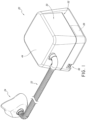
- a breathing assistance apparatus 20 is shown that is arranged and configured in accordance with certain features, aspects and advantages of the present technology.
- the breathing assistance apparatus 20 is connected to a conduit 22 and the conduit 22 is connected to a user interface 24, such as a breathing mask or the like. Any suitable user interface 24 can be used.
- the breathing assistance apparatus 20 also is configured to humidify the flow of pressurized breathing gases prior to deliver to the user.
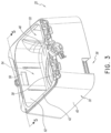
- the illustrated breathing assistance apparatus 20 also comprises a humidification chamber 28.
- the humidification chamber 28 can be removable from the breathing assistance apparatus 20. Any suitable construction can be used for the humidification chamber 28.
- the humidification chamber 28 can be configured to contain a volume of liquid, such as water. The flow of pressurized breathing gases can pass over the volume of liquid en route to the user such that the flow of pressurized breathing gases can increase in humidity.
- the lower housing 34 can include an air inlet 36 through which the flow generator 26 draws air.
- the flow generator 26 can be mounted to or within the lower housing 34.
- the lower housing 34 also can support a heating element 38.
- the liquid within the humidification chamber 28 can be heated through an interaction with the heating element 38.
- the heating element 38 can be a heater plate and the humidification chamber 28 can rest on the heater plate. Other configurations are possible.
- the main body 30 comprises at least one outer wall 40.
- the main body 30 comprises four generally vertical outer walls 40.
- An upper portion of the at least one wall 40 generally defines an opening 42.
- the opening 42 can be closed with a lid 44.
- the lid 44 can seal the opening 42 in some configurations.
- a liquid containment compartment 54 is separated from the humidification compartment 50. According to the present invention, the liquid containment compartment 54 limits the travel of liquid that may spill from the humidification chamber 28. The liquid containment compartment 54 limits the travel of liquid that may be spilled within the humidification compartment 50 and outside of the humidification chamber 28.
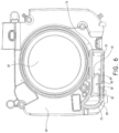
- a second opening 58 defines a gas inlet into the liquid containment compartment 54 and a gas outlet for flow from a passage 66 leading from the flow generator 26.
- the first opening 56 is in the upper housing 32 and the second opening 58 is in the lower housing 34.
- the first opening 56 is offset both horizontally and vertically from the second opening.
- the first opening 56 is offset at least horizontally from the second opening 58, as shown in Figure 5 (i.e., the first opening 56 is to the right of the second opening 58).
- the first opening 56 is completely offset at least horizontally from the second opening 58.
- the two openings 56, 58 are offset in two orthogonal directions (e.g., horizontally and vertically). In some configurations, the two openings 56, 58 are offset in three orthogonal directions (horizontally in two orthogonal directions and vertically). Offset positioning of the first opening 56 relative to the second opening 58 reduces the likelihood of liquids spilling, draining, depositing or otherwise passing through the first opening 56 into the liquid containment compartment 54 passing further upstream toward the flow generator 26 relative to the liquid containment chamber 54. In other words, liquid is unlikely to easily pass through the first opening 56 and into the second opening 58. As such, liquid infiltration from the humidification chamber 28 toward the flow generator 26 can be inhibited.
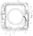
- the liquid containment compartment 54 comprises at least a lower wall 70.
- the lower wall 70 can be formed as part of the lower housing 34.
- a ridge 72 can be defined on a portion of the lower housing 34.
- the illustrated ridge 72 can generally encircle a reservoir 74.
- the ridge 72 generally surrounds the second opening 58.
- Other configurations are possible.
- the second opening 58 is vertically higher than the lower wall 70.
- the second opening 58 spans a vertical distance and the lowermost portion of the second opening 58 is vertically higher than the lower wall 70.
- the lower wall 70 can span a vertical distance (i.e., not be substantially flat) and the second opening 58 is vertically higher than any portion of the lower wall 70 that is directly adjacent to the second opening 58.
- At least a portion of the liquid containment compartment 54 is defined between the inner wall 52 and the outer wall 40 of the main body 30.
- at least a first wall 78 and, in some configurations, a second wall 84 can cooperate with the inner wall 52 and the outer wall 40 to define the sides of the liquid containment compartment 54.
- These walls 40, 52, 78, 84 can be integrally formed with the upper housing 32.
- the ridge 72 can match the configuration of these walls 40, 52, 78, 84. As such, the ridge 72 and these walls 40, 52, 78 and 84 can abut each other.
- a seal 86 can be positioned between the upper housing 32 and the lower housing 34. In the illustrated configuration, the seal 86 is positioned within a groove 90 (see Figure 5 ). The groove 90 may be positioned within the ridge 72.
- the seal 86 can be formed of a more resilient material than the ridge 72. As such, the seal 86 can deform upon contact with the walls 40, 52, 78, 84. The compression of the seal 86 can reduce the likelihood of liquid or gas leaks into or out of the liquid containment compartment 54.
Landscapes
- Health & Medical Sciences (AREA)
- Emergency Medicine (AREA)
- Pulmonology (AREA)
- Engineering & Computer Science (AREA)
- Anesthesiology (AREA)
- Biomedical Technology (AREA)
- Heart & Thoracic Surgery (AREA)
- Hematology (AREA)
- Life Sciences & Earth Sciences (AREA)
- Animal Behavior & Ethology (AREA)
- General Health & Medical Sciences (AREA)
- Public Health (AREA)
- Veterinary Medicine (AREA)
- Air Humidification (AREA)
- Respiratory Apparatuses And Protective Means (AREA)
- Devices For Medical Bathing And Washing (AREA)
Applications Claiming Priority (4)
| Application Number | Priority Date | Filing Date | Title |
|---|---|---|---|
| US201461933775P | 2014-01-30 | 2014-01-30 | |
| PCT/NZ2015/050005 WO2015115916A1 (en) | 2014-01-30 | 2015-01-29 | Breathing assistance apparatus with liquid containment |
| EP19192027.1A EP3590571B1 (en) | 2014-01-30 | 2015-01-29 | Breathing assistance apparatus with liquid containment |
| EP15743509.0A EP3099366B1 (en) | 2014-01-30 | 2015-01-29 | Breathing assistance apparatus with liquid containment |
Related Parent Applications (3)
| Application Number | Title | Priority Date | Filing Date |
|---|---|---|---|
| EP19192027.1A Division-Into EP3590571B1 (en) | 2014-01-30 | 2015-01-29 | Breathing assistance apparatus with liquid containment |
| EP19192027.1A Division EP3590571B1 (en) | 2014-01-30 | 2015-01-29 | Breathing assistance apparatus with liquid containment |
| EP15743509.0A Division EP3099366B1 (en) | 2014-01-30 | 2015-01-29 | Breathing assistance apparatus with liquid containment |
Publications (2)
| Publication Number | Publication Date |
|---|---|
| EP4218881A1 EP4218881A1 (en) | 2023-08-02 |
| EP4218881B1 true EP4218881B1 (en) | 2025-07-02 |
Family
ID=53757394
Family Applications (3)
| Application Number | Title | Priority Date | Filing Date |
|---|---|---|---|
| EP23165211.6A Active EP4218881B1 (en) | 2014-01-30 | 2015-01-29 | Breathing assistance apparatus with liquid containment |
| EP19192027.1A Active EP3590571B1 (en) | 2014-01-30 | 2015-01-29 | Breathing assistance apparatus with liquid containment |
| EP15743509.0A Active EP3099366B1 (en) | 2014-01-30 | 2015-01-29 | Breathing assistance apparatus with liquid containment |
Family Applications After (2)
| Application Number | Title | Priority Date | Filing Date |
|---|---|---|---|
| EP19192027.1A Active EP3590571B1 (en) | 2014-01-30 | 2015-01-29 | Breathing assistance apparatus with liquid containment |
| EP15743509.0A Active EP3099366B1 (en) | 2014-01-30 | 2015-01-29 | Breathing assistance apparatus with liquid containment |
Country Status (10)
| Country | Link |
|---|---|
| US (3) | US10493229B2 (enExample) |
| EP (3) | EP4218881B1 (enExample) |
| JP (4) | JP6586097B2 (enExample) |
| CN (2) | CN105939748B (enExample) |
| AU (4) | AU2015211502B2 (enExample) |
| BR (1) | BR112016016630B1 (enExample) |
| CA (2) | CA2936923C (enExample) |
| GB (2) | GB2559901B (enExample) |
| SG (2) | SG11201605793SA (enExample) |
| WO (1) | WO2015115916A1 (enExample) |
Families Citing this family (7)
| Publication number | Priority date | Publication date | Assignee | Title |
|---|---|---|---|---|
| EP4218881B1 (en) | 2014-01-30 | 2025-07-02 | Fisher & Paykel Healthcare Limited | Breathing assistance apparatus with liquid containment |
| USD790683S1 (en) * | 2015-03-11 | 2017-06-27 | Resmed Limited | Pressurized air delivery console |
| AU2017287791B2 (en) * | 2016-07-01 | 2022-03-17 | Fisher & Paykel Healthcare Limited | Improvements relating to a respiratory device |
| US10957966B2 (en) | 2018-02-06 | 2021-03-23 | Barkan Mounts Ltd | Wall mount for screens with an integrated antenna |
| CN112546379B (zh) * | 2018-10-26 | 2025-08-05 | 北京瑞迈特医疗科技股份有限公司 | 呼吸通气设备 |
| JP2023551779A (ja) * | 2020-10-29 | 2023-12-13 | レスメド・プロプライエタリー・リミテッド | 液体を呼吸デバイスから分流させるためのアセンブリ |
| CN114272487B (zh) * | 2021-12-27 | 2024-05-03 | 北京谊安健康科技有限公司 | 一种防止液体回流的湿化装置 |
Family Cites Families (27)
| Publication number | Priority date | Publication date | Assignee | Title |
|---|---|---|---|---|
| US4028444A (en) * | 1974-03-25 | 1977-06-07 | Chemetron Corporation | Humidifier and automatic control system therefor |
| US6398197B1 (en) * | 1999-05-10 | 2002-06-04 | Fisher & Paykel Limited | Water chamber |
| EP2335761B1 (en) * | 2001-02-16 | 2017-04-05 | ResMed Limited | Humidifier with structure to prevent backflow of liquid through the humidifier inlet |
| DE10226160B4 (de) * | 2002-06-12 | 2009-06-18 | Hoffrichter Gmbh | Luftbefeuchter für ein Beatmungsgerät |
| US20030188746A1 (en) * | 2003-05-13 | 2003-10-09 | Roger Daugherty | Apparatus and method for humidification of inspired gases |
| ATE517649T1 (de) * | 2003-06-20 | 2011-08-15 | Resmed Ltd | Atemgas-gerät mit befeuchter |
| AU2013201490B2 (en) * | 2003-06-20 | 2014-09-25 | ResMed Pty Ltd | Breathable Gas Apparatus with Humidifier |
| AU2003903139A0 (en) * | 2003-06-20 | 2003-07-03 | Resmed Limited | Breathable gas apparatus with humidifier |
| CN2695846Y (zh) * | 2003-08-07 | 2005-04-27 | 北京杰富瑞科技有限公司 | 防反流加温湿化装置 |
| EP1656173B1 (en) | 2003-08-20 | 2015-12-30 | Fisher & Paykel Healthcare Limited | Water chamber for humidifier |
| NZ564886A (en) * | 2005-08-15 | 2011-02-25 | Resmed Ltd | Humidifier for CPAP device with tub base plate forced into engagement with heater plate by cradle retaining structure |
| US8701662B2 (en) * | 2005-09-27 | 2014-04-22 | Ric Investments, Llc | Humidifier with back-flow prevention valve |
| JP5009989B2 (ja) * | 2006-08-25 | 2012-08-29 | フィッシャー アンド ペイケル ヘルスケア リミテッド | 内部発熱体及びヒータープレートを備えた加湿器 |
| CN102921087B (zh) * | 2006-11-06 | 2016-10-05 | 菲舍尔和佩克尔保健有限公司 | 集成的加湿室和盖 |
| US8905023B2 (en) * | 2007-10-05 | 2014-12-09 | Vapotherm, Inc. | Hyperthermic humidification system |
| WO2009156921A1 (en) | 2008-06-27 | 2009-12-30 | Koninklijke Philips Electronics N.V. | Humidifier for a breathing system |
| NZ590924A (en) * | 2008-09-17 | 2013-08-30 | Resmed Ltd | Humidification of respiratory gases |
| KR101532576B1 (ko) * | 2008-11-28 | 2015-06-30 | 엘지전자 주식회사 | 가습기 |
| CA2764382C (en) * | 2009-06-05 | 2017-03-21 | Fisher & Paykel Healthcare Limited | Humidifier heater base |
| DE112010005006T5 (de) * | 2009-12-23 | 2012-11-15 | Fisher & Paykel Healthcare Ltd. | Zuführungsvorrichtung für befeuchtete Gase und Verfahren für ihre Steuerung |
| WO2012123854A1 (en) * | 2011-03-14 | 2012-09-20 | Koninklijke Philips Electronics N.V. | Humidifier with liquid ingress protection |
| US9849258B2 (en) * | 2011-04-05 | 2017-12-26 | Resmed Limited | Respiratory breathing apparatus |
| DE11005292T1 (de) * | 2011-06-29 | 2013-07-25 | Healthc'air | Behälter für Gerät zur Atmungsunterstützung |
| US10213573B2 (en) * | 2011-12-22 | 2019-02-26 | Resmed Limited | Humidifiers for respiratory apparatus |
| EP3708213B1 (en) * | 2012-03-15 | 2022-11-02 | ResMed Pty Ltd | Heating apparatus |
| CN202654514U (zh) * | 2012-05-22 | 2013-01-09 | 北京怡和嘉业医疗科技有限公司 | 加湿设备和具有该加湿设备的通气治疗设备 |
| EP4218881B1 (en) | 2014-01-30 | 2025-07-02 | Fisher & Paykel Healthcare Limited | Breathing assistance apparatus with liquid containment |
-
2015
- 2015-01-29 EP EP23165211.6A patent/EP4218881B1/en active Active
- 2015-01-29 WO PCT/NZ2015/050005 patent/WO2015115916A1/en not_active Ceased
- 2015-01-29 CA CA2936923A patent/CA2936923C/en active Active
- 2015-01-29 EP EP19192027.1A patent/EP3590571B1/en active Active
- 2015-01-29 CN CN201580006405.9A patent/CN105939748B/zh active Active
- 2015-01-29 SG SG11201605793SA patent/SG11201605793SA/en unknown
- 2015-01-29 SG SG10201907307SA patent/SG10201907307SA/en unknown
- 2015-01-29 US US15/113,787 patent/US10493229B2/en active Active
- 2015-01-29 GB GB1805636.6A patent/GB2559901B/en active Active
- 2015-01-29 BR BR112016016630-2A patent/BR112016016630B1/pt active IP Right Grant
- 2015-01-29 AU AU2015211502A patent/AU2015211502B2/en active Active
- 2015-01-29 GB GB1612153.5A patent/GB2541117B/en active Active
- 2015-01-29 CN CN201911341572.5A patent/CN111068157B/zh active Active
- 2015-01-29 JP JP2016549441A patent/JP6586097B2/ja active Active
- 2015-01-29 EP EP15743509.0A patent/EP3099366B1/en active Active
- 2015-01-29 CA CA3159009A patent/CA3159009A1/en active Pending
-
2019
- 2019-09-06 JP JP2019162901A patent/JP6974406B2/ja active Active
- 2019-10-30 US US16/668,764 patent/US11305090B2/en active Active
-
2020
- 2020-04-08 AU AU2020202424A patent/AU2020202424B2/en active Active
-
2021
- 2021-11-04 JP JP2021180027A patent/JP2022016476A/ja active Pending
- 2021-11-25 AU AU2021273596A patent/AU2021273596B2/en active Active
-
2022
- 2022-03-15 US US17/654,894 patent/US20220280745A1/en active Pending
-
2023
- 2023-12-04 AU AU2023274229A patent/AU2023274229B2/en active Active
- 2023-12-25 JP JP2023218243A patent/JP2024028308A/ja active Pending
Also Published As
Similar Documents
| Publication | Publication Date | Title |
|---|---|---|
| AU2023274229B2 (en) | Breathing Assistance Apparatus with Liquid Containment | |
| EP2686053B1 (en) | Humidifier with liquid ingress protection | |
| US20180078729A1 (en) | Vapor delivery system | |
| JP2017504442A5 (enExample) | ||
| EP2842589A2 (en) | Humidifier for respiratory apparatus | |
| EP4294487B1 (en) | Integrated humidifier water ingress protection | |
| TWM481735U (zh) | 加濕裝置及使用其之呼吸設備 | |
| AU2010342297B2 (en) | Humidification system with signal transmission optimization | |
| US20170336086A1 (en) | Liquid container for gas humidification and gas humidification method |
Legal Events
| Date | Code | Title | Description |
|---|---|---|---|
| PUAI | Public reference made under article 153(3) epc to a published international application that has entered the european phase |
Free format text: ORIGINAL CODE: 0009012 |
|
| STAA | Information on the status of an ep patent application or granted ep patent |
Free format text: STATUS: THE APPLICATION HAS BEEN PUBLISHED |
|
| AC | Divisional application: reference to earlier application |
Ref document number: 3099366 Country of ref document: EP Kind code of ref document: P Ref document number: 3590571 Country of ref document: EP Kind code of ref document: P |
|
| AK | Designated contracting states |
Kind code of ref document: A1 Designated state(s): AL AT BE BG CH CY CZ DE DK EE ES FI FR GB GR HR HU IE IS IT LI LT LU LV MC MK MT NL NO PL PT RO RS SE SI SK SM TR |
|
| STAA | Information on the status of an ep patent application or granted ep patent |
Free format text: STATUS: REQUEST FOR EXAMINATION WAS MADE |
|
| 17P | Request for examination filed |
Effective date: 20240202 |
|
| RBV | Designated contracting states (corrected) |
Designated state(s): AL AT BE BG CH CY CZ DE DK EE ES FI FR GB GR HR HU IE IS IT LI LT LU LV MC MK MT NL NO PL PT RO RS SE SI SK SM TR |
|
| GRAP | Despatch of communication of intention to grant a patent |
Free format text: ORIGINAL CODE: EPIDOSNIGR1 |
|
| STAA | Information on the status of an ep patent application or granted ep patent |
Free format text: STATUS: GRANT OF PATENT IS INTENDED |
|
| RIC1 | Information provided on ipc code assigned before grant |
Ipc: A61M 16/00 20060101ALI20240916BHEP Ipc: A61M 16/16 20060101AFI20240916BHEP |
|
| INTG | Intention to grant announced |
Effective date: 20241014 |
|
| GRAJ | Information related to disapproval of communication of intention to grant by the applicant or resumption of examination proceedings by the epo deleted |
Free format text: ORIGINAL CODE: EPIDOSDIGR1 |
|
| STAA | Information on the status of an ep patent application or granted ep patent |
Free format text: STATUS: REQUEST FOR EXAMINATION WAS MADE |
|
| GRAP | Despatch of communication of intention to grant a patent |
Free format text: ORIGINAL CODE: EPIDOSNIGR1 |
|
| STAA | Information on the status of an ep patent application or granted ep patent |
Free format text: STATUS: GRANT OF PATENT IS INTENDED |
|
| INTG | Intention to grant announced |
Effective date: 20250131 |
|
| GRAS | Grant fee paid |
Free format text: ORIGINAL CODE: EPIDOSNIGR3 |
|
| GRAA | (expected) grant |
Free format text: ORIGINAL CODE: 0009210 |
|
| STAA | Information on the status of an ep patent application or granted ep patent |
Free format text: STATUS: THE PATENT HAS BEEN GRANTED |
|
| AC | Divisional application: reference to earlier application |
Ref document number: 3099366 Country of ref document: EP Kind code of ref document: P Ref document number: 3590571 Country of ref document: EP Kind code of ref document: P |
|
| AK | Designated contracting states |
Kind code of ref document: B1 Designated state(s): AL AT BE BG CH CY CZ DE DK EE ES FI FR GB GR HR HU IE IS IT LI LT LU LV MC MK MT NL NO PL PT RO RS SE SI SK SM TR |
|
| REG | Reference to a national code |
Ref country code: GB Ref legal event code: FG4D |
|
| REG | Reference to a national code |
Ref country code: CH Ref legal event code: EP |
|
| REG | Reference to a national code |
Ref country code: DE Ref legal event code: R096 Ref document number: 602015091961 Country of ref document: DE |
|
| REG | Reference to a national code |
Ref country code: IE Ref legal event code: FG4D |
|
| P01 | Opt-out of the competence of the unified patent court (upc) registered |
Free format text: CASE NUMBER: APP_30765/2025 Effective date: 20250626 |
|
| REG | Reference to a national code |
Ref country code: NL Ref legal event code: MP Effective date: 20250702 |
|
| PG25 | Lapsed in a contracting state [announced via postgrant information from national office to epo] |
Ref country code: PT Free format text: LAPSE BECAUSE OF FAILURE TO SUBMIT A TRANSLATION OF THE DESCRIPTION OR TO PAY THE FEE WITHIN THE PRESCRIBED TIME-LIMIT Effective date: 20251103 |
|
| PG25 | Lapsed in a contracting state [announced via postgrant information from national office to epo] |
Ref country code: NL Free format text: LAPSE BECAUSE OF FAILURE TO SUBMIT A TRANSLATION OF THE DESCRIPTION OR TO PAY THE FEE WITHIN THE PRESCRIBED TIME-LIMIT Effective date: 20250702 |
|
| REG | Reference to a national code |
Ref country code: AT Ref legal event code: MK05 Ref document number: 1808568 Country of ref document: AT Kind code of ref document: T Effective date: 20250702 |
|
| PG25 | Lapsed in a contracting state [announced via postgrant information from national office to epo] |
Ref country code: IS Free format text: LAPSE BECAUSE OF FAILURE TO SUBMIT A TRANSLATION OF THE DESCRIPTION OR TO PAY THE FEE WITHIN THE PRESCRIBED TIME-LIMIT Effective date: 20251102 |
|
| PGFP | Annual fee paid to national office [announced via postgrant information from national office to epo] |
Ref country code: GB Payment date: 20251220 Year of fee payment: 12 |
|
| PG25 | Lapsed in a contracting state [announced via postgrant information from national office to epo] |
Ref country code: NO Free format text: LAPSE BECAUSE OF FAILURE TO SUBMIT A TRANSLATION OF THE DESCRIPTION OR TO PAY THE FEE WITHIN THE PRESCRIBED TIME-LIMIT Effective date: 20251002 |
|
| REG | Reference to a national code |
Ref country code: LT Ref legal event code: MG9D |
|
| PG25 | Lapsed in a contracting state [announced via postgrant information from national office to epo] |
Ref country code: AT Free format text: LAPSE BECAUSE OF FAILURE TO SUBMIT A TRANSLATION OF THE DESCRIPTION OR TO PAY THE FEE WITHIN THE PRESCRIBED TIME-LIMIT Effective date: 20250702 |
|
| PG25 | Lapsed in a contracting state [announced via postgrant information from national office to epo] |
Ref country code: FI Free format text: LAPSE BECAUSE OF FAILURE TO SUBMIT A TRANSLATION OF THE DESCRIPTION OR TO PAY THE FEE WITHIN THE PRESCRIBED TIME-LIMIT Effective date: 20250702 |
|
| PG25 | Lapsed in a contracting state [announced via postgrant information from national office to epo] |
Ref country code: HR Free format text: LAPSE BECAUSE OF FAILURE TO SUBMIT A TRANSLATION OF THE DESCRIPTION OR TO PAY THE FEE WITHIN THE PRESCRIBED TIME-LIMIT Effective date: 20250702 |
|
| PGFP | Annual fee paid to national office [announced via postgrant information from national office to epo] |
Ref country code: FR Payment date: 20251217 Year of fee payment: 12 |