EP4218656A1 - Method for positioning a medical instrument for invasive surgery - Google Patents
Method for positioning a medical instrument for invasive surgery Download PDFInfo
- Publication number
- EP4218656A1 EP4218656A1 EP21873041.4A EP21873041A EP4218656A1 EP 4218656 A1 EP4218656 A1 EP 4218656A1 EP 21873041 A EP21873041 A EP 21873041A EP 4218656 A1 EP4218656 A1 EP 4218656A1
- Authority
- EP
- European Patent Office
- Prior art keywords
- patient
- dislocation
- surgery
- medical instrument
- protrusions
- Prior art date
- Legal status (The legal status is an assumption and is not a legal conclusion. Google has not performed a legal analysis and makes no representation as to the accuracy of the status listed.)
- Pending
Links
- 238000001356 surgical procedure Methods 0.000 title claims abstract description 38
- 238000000034 method Methods 0.000 title claims description 8
- 238000003780 insertion Methods 0.000 claims abstract description 13
- 230000037431 insertion Effects 0.000 claims abstract description 13
- 239000003550 marker Substances 0.000 claims abstract description 11
- 230000000241 respiratory effect Effects 0.000 claims abstract description 10
- 238000005286 illumination Methods 0.000 claims abstract description 6
- 230000029058 respiratory gaseous exchange Effects 0.000 claims description 6
- 230000037361 pathway Effects 0.000 claims description 4
- 238000013480 data collection Methods 0.000 claims description 2
- 238000009434 installation Methods 0.000 claims 1
- 238000012544 monitoring process Methods 0.000 abstract description 14
- 239000003814 drug Substances 0.000 abstract description 5
- 210000000056 organ Anatomy 0.000 abstract description 4
- 238000002591 computed tomography Methods 0.000 abstract description 3
- 230000006872 improvement Effects 0.000 abstract description 3
- 238000012937 correction Methods 0.000 abstract description 2
- 238000005259 measurement Methods 0.000 abstract description 2
- 230000000007 visual effect Effects 0.000 abstract description 2
- 238000005516 engineering process Methods 0.000 description 4
- 238000004458 analytical method Methods 0.000 description 3
- 230000010354 integration Effects 0.000 description 3
- 238000013459 approach Methods 0.000 description 2
- 238000010276 construction Methods 0.000 description 2
- 238000002594 fluoroscopy Methods 0.000 description 2
- 210000001519 tissue Anatomy 0.000 description 2
- 210000001835 viscera Anatomy 0.000 description 2
- 230000004308 accommodation Effects 0.000 description 1
- 239000000853 adhesive Substances 0.000 description 1
- 230000001070 adhesive effect Effects 0.000 description 1
- 239000012790 adhesive layer Substances 0.000 description 1
- 239000002390 adhesive tape Substances 0.000 description 1
- 238000013473 artificial intelligence Methods 0.000 description 1
- 230000015572 biosynthetic process Effects 0.000 description 1
- 210000000746 body region Anatomy 0.000 description 1
- 230000008859 change Effects 0.000 description 1
- 238000013170 computed tomography imaging Methods 0.000 description 1
- 230000008602 contraction Effects 0.000 description 1
- 230000003247 decreasing effect Effects 0.000 description 1
- 238000001514 detection method Methods 0.000 description 1
- 238000011161 development Methods 0.000 description 1
- 230000003993 interaction Effects 0.000 description 1
- 239000010410 layer Substances 0.000 description 1
- 230000003902 lesion Effects 0.000 description 1
- 238000002595 magnetic resonance imaging Methods 0.000 description 1
- 239000000463 material Substances 0.000 description 1
- 238000012806 monitoring device Methods 0.000 description 1
- 230000003287 optical effect Effects 0.000 description 1
- 230000008855 peristalsis Effects 0.000 description 1
- 230000008569 process Effects 0.000 description 1
- 238000012545 processing Methods 0.000 description 1
- 230000005855 radiation Effects 0.000 description 1
- 210000002027 skeletal muscle Anatomy 0.000 description 1
- 230000002269 spontaneous effect Effects 0.000 description 1
- 238000002604 ultrasonography Methods 0.000 description 1
- 238000011179 visual inspection Methods 0.000 description 1
- 238000012800 visualization Methods 0.000 description 1
Images


Classifications
-
- A—HUMAN NECESSITIES
- A61—MEDICAL OR VETERINARY SCIENCE; HYGIENE
- A61B—DIAGNOSIS; SURGERY; IDENTIFICATION
- A61B90/00—Instruments, implements or accessories specially adapted for surgery or diagnosis and not covered by any of the groups A61B1/00 - A61B50/00, e.g. for luxation treatment or for protecting wound edges
- A61B90/10—Instruments, implements or accessories specially adapted for surgery or diagnosis and not covered by any of the groups A61B1/00 - A61B50/00, e.g. for luxation treatment or for protecting wound edges for stereotaxic surgery, e.g. frame-based stereotaxis
- A61B90/11—Instruments, implements or accessories specially adapted for surgery or diagnosis and not covered by any of the groups A61B1/00 - A61B50/00, e.g. for luxation treatment or for protecting wound edges for stereotaxic surgery, e.g. frame-based stereotaxis with guides for needles or instruments, e.g. arcuate slides or ball joints
- A61B90/13—Instruments, implements or accessories specially adapted for surgery or diagnosis and not covered by any of the groups A61B1/00 - A61B50/00, e.g. for luxation treatment or for protecting wound edges for stereotaxic surgery, e.g. frame-based stereotaxis with guides for needles or instruments, e.g. arcuate slides or ball joints guided by light, e.g. laser pointers
-
- A—HUMAN NECESSITIES
- A61—MEDICAL OR VETERINARY SCIENCE; HYGIENE
- A61B—DIAGNOSIS; SURGERY; IDENTIFICATION
- A61B90/00—Instruments, implements or accessories specially adapted for surgery or diagnosis and not covered by any of the groups A61B1/00 - A61B50/00, e.g. for luxation treatment or for protecting wound edges
- A61B90/36—Image-producing devices or illumination devices not otherwise provided for
- A61B90/37—Surgical systems with images on a monitor during operation
- A61B2090/376—Surgical systems with images on a monitor during operation using X-rays, e.g. fluoroscopy
- A61B2090/3762—Surgical systems with images on a monitor during operation using X-rays, e.g. fluoroscopy using computed tomography systems [CT]
-
- A—HUMAN NECESSITIES
- A61—MEDICAL OR VETERINARY SCIENCE; HYGIENE
- A61B—DIAGNOSIS; SURGERY; IDENTIFICATION
- A61B90/00—Instruments, implements or accessories specially adapted for surgery or diagnosis and not covered by any of the groups A61B1/00 - A61B50/00, e.g. for luxation treatment or for protecting wound edges
- A61B90/39—Markers, e.g. radio-opaque or breast lesions markers
- A61B2090/3966—Radiopaque markers visible in an X-ray image
Definitions
- the group of inventions is related to medicine, namely, X-ray computed tomography (X-ray CT)-guided surgical procedures and means of surgical instrument positioning and orienting, e.g. in diagnostic radiology.
- X-ray CT X-ray computed tomography
- the problem is in change of a spatial position of a medical instrument introduced into a human body due to human body movements, organs and tissues disposition during a surgical procedure (caused by various amplitude respiratory excursions, skeletal muscles contractions, internal organ disposition due to peristalsis). Changes in spatial position of instruments lead to a decreased precision of a procedure, require additional alignments control, increase the radiation exposure and surgery time and risk of complications, deteriorate the quality of surgical procedures and require additional equipment for monitoring.
- Real-time X-ray monitoring solutions that are not conventional for a CT scanner (X-ray television fluoroscopy equipment) are characterized by a lower scanning resolution and inferior visualization, so the procedure is not as detailed as in CT scanning modality.
- This approach requires an integration of additional output devices to user interfaces, it requires rapid human-assisted analysis and interpretation (within a few seconds) in order to make decision and subsequent correct positioning of the instrument or human body.
- Such integration currently still requires development of medical image processing algorithms, improvements of instrumental and hardware components of utilized medical equipment, high computing capacity of workstations, using artificial intelligence to aid a human in fast integration, analysis, and interpretation of data generated during a surgical procedure, which remains an unsolved problem of the state-of-the-art medicine and technology. It should be noted that so-called real-time monitoring is provisional and only means a monitoring with a higher scanning frequency and higher frame rate of obtained images.
- Real-time monitoring devices based on other physical principles have the same disadvantages as X-ray units. Its application is limited by more heterogeneous data transmitted to a user interface. The state-of-the-art technology does not provide fast and direct interaction during analysis of data transmitted by such means due to differences in vendor approach, property rights, interface protocols, etc. Some control units do not provide information on a lesion and internal organs, just reflecting spatial interrelations between its sensors (electromagnetic monitoring means) or an instrument position on a human body surface (optic navigation systems).
- the available devices of passive monitoring including stereotactic devices, act as a markup to maintain a medical instrument in a required spatial position, but do not provide the ability of respiratory movement or spontaneous movemens assessment.
- a radiopaque grid for surgical field markup is well validated device. It contains of a basal layer made of a radiolucent material and radiopaque filaments incorporated in a rectangular grid with rectangular cells dimensioned of 20 to 50 mm. One side of a base has an adhesive layer along the perimeter for fixation to patient's skin ( RU 152847 U1, publ. June 20, 2015 , Bul. No. 17).
- a stereotactic medical instrument holder including a trajectory indicator installed in arch-shaped brackets fixed in a ring-shaped base and rotatable in two mutually perpendicular vertical planes is also developed and validated (description for Patent RU 2569720, M ⁇ K A61B 19/00 (2006.01), published on November 27, 2015 ).
- the objective of the invention is to develop a mean for monitoring and navigation for performing CT-guided surgical procedures in medicine, radiology, surgery and medical technology.
- the technical result is an improvement of medical instrument positioning quality under conditions of various human body movements during surgery by means of visual and radiological CT monitoring of tissue, organ and human body parts dislocation during surgery, ability of precise measurements of dislocation and in-time repositioning correction due to respiratory excursions during surgery.
- the technical result is achieved by a method of invasive surgery instrument positioning containing steps where the instrument pathway position is determined, individual patient's data is collected and an optimal position is determined for locating an orienting device implemented as a stereotactic medical instrument holder including a trajectory indicator installed in arch-shaped brackets fixed in a ring-shaped base and rotatable in two mutually perpendicular vertical planes; by a data collection step including determination of a patient's body surface dislocation during respiration and a corresponding respiratory movements amplitude by locating a radiopaque linear marker on a surgery table under a patient's body in the axial plane of the surgery object and by locating a coordinate radiopaque gride implemented as a rectangular frame with transverse jumper forming internal rectangular cells and two rows of outer rectangular cells located along transverse sides of a frame over a patient's body in a planned surgery area.
- an orienting device implemented as a stereotactic medical instrument holder including a trajectory indicator installed in arch-shaped brackets fixed in a
- the grid is located in such a way that internal cell jumpers are oriented in a sagittal plane and outer cell jumpers are oriented in an axial plane, and the magnitude of a patient's body dislocation during respiration is assessed by a dislocation of outer cell jumpers in relation to a linear marker on a surgical table and in relation to a line created by laser illumination of a diagnostic equipment.
- a body region movement amplitude is 15-30 mm or less
- lines are drawn on the skin in axial and sagittal planes, marking a medical instrument insertion site with subsequent installing in the latter a stereotactic holder having four pairs of radiopaque markers shaped as parallel protrusions located on a base on both sides of brackets fixtures, while a holder is installed in such a way that an axial and a sagittal marker lines are located between protrusions.
- a coordinate radiopaque grid (RCG) for a surgical field markup is presented by a rectangular frame with transverse jumper forming internal rectangular cells and has a number of outer rectangular cells on each transverse side of a frame.
- a stereotactic medical instrument holder including a trajectory indicator installed in arch-shaped brackets fixed in a ring-shaped base and rotatable in two mutually perpendicular vertical planes is additionally equipped with four pairs of radiopaque markers shaped as parallel protrusions located on a base on both sides of brackets fixtures.
- Fig.1 illustrates a coordinate radiopaque grid (RCG);
- Fig. 7 illustrates a stereotactic holder;
- Fig.8 illustrates a stereotactic holder radiopaque markers pair.
- RCG markup instrument for surgical field markup (Fig.6) is a rectangular-shaped frame with transverse parallel jumpers forming internal rectangular cells. Each transverse side of a frame has a number of outer rectangular cells with sides perpendicular to transverse jumper, forming outer protrusions.
- RCG construction elements may vary.
- the distance between outer protrusions and internal jumper may be different.
- the distance between protrusions on contralateral sides of a frame may be various.
- RCG may have graduation with different graduation values.
- Stereotactic holder (Fig.7) has four pairs of radiopaque markers shaped as parallel protrusions (Fig.8) located at an area of upper and lower segments' fixture to a base.
- the protrusions are developed for alignment with corresponding RCG and RLM construction elements.
- the protrusions may be located along the outer and/or inner circumference of a stereotactic holder base and may have different opacities under fluoroscopy, X-ray computed tomography or magnetic resonance imaging.
- a stereotactic holder may be equipped with fixation outfit to adhere an underlying surface (adhesive base, dressing, adhesive tape, suture holes, etc.)
- RLM markup instrument may have graduation in different graduation values.
- the method of invasive surgery instrument positioning includes the following steps.
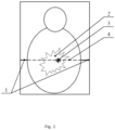
- a radiopaque linear marker (RLM) oriented in axial plane is placed under a patient's body on a diagnostic equipment table in a plane of a planned intervention.
- RLM markup instrument position corresponding to an axial plane is controlled by a CT scanner midline laser in axial plane ( Fig. 1 ).
- a RLM markup instrument may have graduation.
- a slice number locating a closest RLM markup instrument (relative to the surgery object slice number and medical instrument insertion site on the human body surface as determined at the previous step) is determined. If a single RLM markup was placed, the slice corresponding to it is chosen.
- a CT scanner table with a patient on it is set up in a position where RLM is aligned with the CT scanner midline laser ( Fig. 1 .).
- a RCG is located over a patient's body surface in a planned surgery area in a way that internal transverse jumpers are oriented in a sagittal plane while outer protrusions are oriented in an axial plane.
- a slice of chosen (or a single) RLM markup instrument with the axial line of a midline laser should be located in a slice array that includes RCG.
- RCG is located over RLM ( Fig. 2 ).
- the patient is instructed to breathe in and out several times and the dislocation of outer protrusions of the RCG markup instrument relative to the line made by the laser illumination of the diagnostic equipment and relative to the RLM markup instrument located under the patient's body on the diagnostic equipment table is evaluated.
- the dislocation is registered by visual inspection.
- a dislocation may be estimated approximately by counting RCG markup instrument outer protrusions located above or below relative to RLM markup instrument and a midline lacer axial line aligned with each other.
- a dislocation may be assessed more precisely in mm using corresponding measuring instruments graded in mm ( Fig. 2 , Fig. 3 , Fig. 6 and Fig. 7).
- Implementation of the 6th step provides information on the dislocation amplitude of a human body fitted with a grid markup tool in relation to stable markers (RLM markup tool aligned with a midline laser axial line).
- RLM markup tool aligned with a midline laser axial line.
- a dislocation value most comfortable for a patient and a corresponding respiratory movements amplitude are chosen.
- the patient is instructed on a requirement to breathe with a certain depth.
- the patient is trained to breathe with a required depth by performing several breathing movement until a required result is achieved as a dislocation with an amplitude chosen.
- Intraoperative CT examination is performed with a scope limited to the surgery area mandatory including RLM and considering their dislocation amplitude.
- the value of a patient's body surface dislocation due to breathing is assessed by dislocation of outer cell jumpers relative to RLM linear marker on a table and relative to a line created by a diagnostic equipment laser illumination; if the body surface dislocation is 15-30 mm or less, lines are drawn on the skin in axial and sagittal planes, marking a medical instrument incretion site with subsequent installing in the latter a stereotactic holder,
- the data obtained on a 7th step are subject to a multiplanar reconstruction using a CT scanner software.
- An axial slice containing an instrument insertion site is chosen.
- a position of this slice on a patient's skin may be obtained by moving a table to a required slice number with a subsequent illumination by a midline laser axial line or by calculating a distance in millimeters from a RCG markup tool upper or lower edge.
- a markup line in axial plane passing through a chosen axial slice is made on the skin with a marker.
- the sagittal slice containing the instrument insertion site is chosen.
- the position of this slice on the skin may be obtained by calculating the closest internal jumper of a RCG markup instrument or by calculating a distance in millimeters from a RCG markup instrument left or right side.
- a markup line in sagittal plane passing through a chosen sagittal slice is made on the skin with a marker.
- a RCG may be removed from the patient's body surface; if indicated, it may be left in the position described in step 5.
- a stereotactic holder is placed in the marked instrument insertion site in a way that stereotactic holder base protrusions are aligned with the axial and sagittal markup lines.
- a stereotactic holder is fixed to the patient's skin and is adjusted to a required tilt angle.
- the dislocation of the stereotactic holder base protrusions in axial plane is checked as in step 6 by visually inspecting a dislocation relative to a RLM aligned with a midline laser axial line.
- the next intraoperative CT examination of a surgical area is performed with detection of surgical site organ, RLM markup instrument and stereotactic holder base protrusions locations are determined. Correspondence to a chosen trajectory is assessed. If necessary, a stereotactic holder tilt angle is adjusted and patient's respiratory movements amplitude are adjusted.
- the medical instrument is inserted into the human body with insertion controlled by stepwise measures at step 13 or as a single-step with additional control by real-time monitoring.
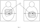
- Stereotactic holder protrusions dislocation and respiratory movements amplitude during insertion are controlled as in step 13. If a CT scanner table with a patient was moved in any direction (e.g. to create more space and freedom of movement for an operator) and a plane of midline laser axial line is not aligned with a plane of a RLM markup instrument, a dislocation of stereotactic holder base protrusions is assessed visually in relation to a current position of a midline laser axial line ( Fig. 4 and Fig. 5 ).
- a follow-up CT examination is performed, after which a medical instrument and stereotactic holder are withdrawn and a surgery is completed.
Abstract
The group of inventions relates to medicine, namely, X-ray computed tomography (X-ray CT) guided surgical procedures and means of surgical instrument positioning and orienting, e.g. in diagnostic radiology. The technical result is the improvement of medical instrument positioning quality under various human body movements during surgery by visual and radiological CT monitoring of dislocation of tissues, organs and human body parts during surgery, and the possibility of precise measurements of dislocation and timely correction of respiratory excursions during surgery. A pre-surgery diagnostic examination is performed, an operation area is determined. An RLM oriented in a direction corresponding to a coronal plane is placed under a patient's body on a diagnostic equipment table surface. An RCG is located over a patient's body surface in a planned surgery area in a way that internal jumpers are oriented in a sagittal plane while outer protrusions are oriented in a coronal plane. The patient is instructed to breathe in and out several times and the dislocation of outer protrusions of the RCG relative to the line made by the laser illumination of the diagnostic equipment and relative to the RLM located under the patient's body on the table is evaluated. The patient is trained to breathe with a required amplitude. The instrument insertion site in a human body is marked with a sterile marker. A stereotactic holder is placed in an instrument insertion site. Position (dislocation) of MR-opaque protrusions of a stereotactic holder base and RCG external protrusions is checked.
Description
- The group of inventions is related to medicine, namely, X-ray computed tomography (X-ray CT)-guided surgical procedures and means of surgical instrument positioning and orienting, e.g. in diagnostic radiology.
- The problem is in change of a spatial position of a medical instrument introduced into a human body due to human body movements, organs and tissues disposition during a surgical procedure (caused by various amplitude respiratory excursions, skeletal muscles contractions, internal organ disposition due to peristalsis). Changes in spatial position of instruments lead to a decreased precision of a procedure, require additional alignments control, increase the radiation exposure and surgery time and risk of complications, deteriorate the quality of surgical procedures and require additional equipment for monitoring.
- This problem is solved in several different ways: by using technical real-time hardware movement monitoring; by using stereotactic devices; by using repeated diagnostic series and stepwise insertion of medical instruments into the human body; by using robots to perform CT-guided surgical procedures. However, there is no universal and effective solution to the above problem as for the state of the art of medicine and technology.
- Thus, state-of-the-art conventional real-time monitoring solutions employed by CT scanner manufacturers do not allow using scanning block sizes required for a full control of instrument movement due to various angles, amplitudes and complexity of movements. Scanning blocks of modern tomographs may include a few to tens of slices with a block length in the range of 3 mm to 20-30 mm. Meanwhile, the movement of certain parts of the human body due to respiratory excursions may exceed up to 5-6 cm and real-time monitoring is not suitable for complete accommodation and control of such spatial changes. It should be noted that the use of a real-time monitoring mode is limited in time due to additional radiation exposure of the patient and medical staff; the duration offered by some CT scanner vendors is only 60 to 90 seconds, what may be insufficient for a CT-guided surgical procedure.
- Real-time X-ray monitoring solutions that are not conventional for a CT scanner (X-ray television fluoroscopy equipment) are characterized by a lower scanning resolution and inferior visualization, so the procedure is not as detailed as in CT scanning modality. This approach requires an integration of additional output devices to user interfaces, it requires rapid human-assisted analysis and interpretation (within a few seconds) in order to make decision and subsequent correct positioning of the instrument or human body. Such integration currently still requires development of medical image processing algorithms, improvements of instrumental and hardware components of utilized medical equipment, high computing capacity of workstations, using artificial intelligence to aid a human in fast integration, analysis, and interpretation of data generated during a surgical procedure, which remains an unsolved problem of the state-of-the-art medicine and technology. It should be noted that so-called real-time monitoring is provisional and only means a monitoring with a higher scanning frequency and higher frame rate of obtained images.
- Real-time monitoring devices based on other physical principles (alternative to X-ray radiation, such as ultrasound units or electromagnetic or optical control systems) have the same disadvantages as X-ray units. Its application is limited by more heterogeneous data transmitted to a user interface. The state-of-the-art technology does not provide fast and direct interaction during analysis of data transmitted by such means due to differences in vendor approach, property rights, interface protocols, etc. Some control units do not provide information on a lesion and internal organs, just reflecting spatial interrelations between its sensors (electromagnetic monitoring means) or an instrument position on a human body surface (optic navigation systems).
- The available devices of passive monitoring, including stereotactic devices, act as a markup to maintain a medical instrument in a required spatial position, but do not provide the ability of respiratory movement or spontaneous movemens assessment.
- There is a well-known group of patient-individualized surgical instrument positioning and orientation in pathway formation devices, it provide a method of invasive surgery instruments positioning. This process includes steps of detecting a pathway position for a medical instrument, obtaining individual patient's data and choosing an optimal position for placing an orienting device implemented as a stereotactic medical instrument holder. It is presented by a trajectory indicator installed in arch-shaped brackets fixed in a ring-shaped base and rotatable in two mutually perpendicular vertical planes components (RU 2 662 872 C2 , MΠK A61B 34/20 (2016.01), A61B 90/11 (2016.01)).
- A radiopaque grid for surgical field markup is well validated device. It contains of a basal layer made of a radiolucent material and radiopaque filaments incorporated in a rectangular grid with rectangular cells dimensioned of 20 to 50 mm. One side of a base has an adhesive layer along the perimeter for fixation to patient's skin (
RU 152847 U1, publ. June 20, 2015 - A stereotactic medical instrument holder including a trajectory indicator installed in arch-shaped brackets fixed in a ring-shaped base and rotatable in two mutually perpendicular vertical planes is also developed and validated (description for Patent
RU 2569720, MΠK A61B 19/00 (2006.01), published on November 27, 2015 - The objective of the invention is to develop a mean for monitoring and navigation for performing CT-guided surgical procedures in medicine, radiology, surgery and medical technology.
- The technical result is an improvement of medical instrument positioning quality under conditions of various human body movements during surgery by means of visual and radiological CT monitoring of tissue, organ and human body parts dislocation during surgery, ability of precise measurements of dislocation and in-time repositioning correction due to respiratory excursions during surgery.
- The technical result is achieved by a method of invasive surgery instrument positioning containing steps where the instrument pathway position is determined, individual patient's data is collected and an optimal position is determined for locating an orienting device implemented as a stereotactic medical instrument holder including a trajectory indicator installed in arch-shaped brackets fixed in a ring-shaped base and rotatable in two mutually perpendicular vertical planes; by a data collection step including determination of a patient's body surface dislocation during respiration and a corresponding respiratory movements amplitude by locating a radiopaque linear marker on a surgery table under a patient's body in the axial plane of the surgery object and by locating a coordinate radiopaque gride implemented as a rectangular frame with transverse jumper forming internal rectangular cells and two rows of outer rectangular cells located along transverse sides of a frame over a patient's body in a planned surgery area. The grid is located in such a way that internal cell jumpers are oriented in a sagittal plane and outer cell jumpers are oriented in an axial plane, and the magnitude of a patient's body dislocation during respiration is assessed by a dislocation of outer cell jumpers in relation to a linear marker on a surgical table and in relation to a line created by laser illumination of a diagnostic equipment. If a body region movement amplitude is 15-30 mm or less, lines are drawn on the skin in axial and sagittal planes, marking a medical instrument insertion site with subsequent installing in the latter a stereotactic holder having four pairs of radiopaque markers shaped as parallel protrusions located on a base on both sides of brackets fixtures, while a holder is installed in such a way that an axial and a sagittal marker lines are located between protrusions.
- A coordinate radiopaque grid (RCG) for a surgical field markup is presented by a rectangular frame with transverse jumper forming internal rectangular cells and has a number of outer rectangular cells on each transverse side of a frame.
- A stereotactic medical instrument holder including a trajectory indicator installed in arch-shaped brackets fixed in a ring-shaped base and rotatable in two mutually perpendicular vertical planes is additionally equipped with four pairs of radiopaque markers shaped as parallel protrusions located on a base on both sides of brackets fixtures.
- It is schematically described in
Fig.1 ,Fig.2 ,Fig.3 ,Fig.4 ,Fig.5 the steps of selection of an invasive surgery instrument position; Fig.6 illustrates a coordinate radiopaque grid (RCG); Fig. 7 illustrates a stereotactic holder; Fig.8 illustrates a stereotactic holder radiopaque markers pair. - RCG markup instrument for surgical field markup (Fig.6) is a rectangular-shaped frame with transverse parallel jumpers forming internal rectangular cells. Each transverse side of a frame has a number of outer rectangular cells with sides perpendicular to transverse jumper, forming outer protrusions.
- The resilience and rigidity of RCG construction elements may vary.
- The distance between outer protrusions and internal jumper may be different. The distance between protrusions on contralateral sides of a frame may be various.
- RCG may have graduation with different graduation values.
- Stereotactic holder (Fig.7) has four pairs of radiopaque markers shaped as parallel protrusions (Fig.8) located at an area of upper and lower segments' fixture to a base. The protrusions are developed for alignment with corresponding RCG and RLM construction elements. The protrusions may be located along the outer and/or inner circumference of a stereotactic holder base and may have different opacities under fluoroscopy, X-ray computed tomography or magnetic resonance imaging.
- A stereotactic holder may be equipped with fixation outfit to adhere an underlying surface (adhesive base, dressing, adhesive tape, suture holes, etc.)
- RLM markup instrument may have graduation in different graduation values.
- The method of invasive surgery instrument positioning includes the following steps.
- 1st. A radiopaque linear marker (RLM) oriented in axial plane is placed under a patient's body on a diagnostic equipment table in a plane of a planned intervention. A RLM markup instrument position corresponding to an axial plane is controlled by a CT scanner midline laser in axial plane (
Fig. 1 ). A RLM markup instrument may have graduation. - 2nd. A pre-surgery diagnostic examination is performed:
- a surgical procedure area is determined,
- a surgery object is detected,
- a required slice number locating a surgery object and a medical instrument insertion site on a human body surface is determined.
- 3rd. A slice number locating a closest RLM markup instrument (relative to the surgery object slice number and medical instrument insertion site on the human body surface as determined at the previous step) is determined. If a single RLM markup was placed, the slice corresponding to it is chosen.
- 4th. A CT scanner table with a patient on it is set up in a position where RLM is aligned with the CT scanner midline laser (
Fig. 1 .). - 5th. A RCG is located over a patient's body surface in a planned surgery area in a way that internal transverse jumpers are oriented in a sagittal plane while outer protrusions are oriented in an axial plane. Here, a slice of chosen (or a single) RLM markup instrument with the axial line of a midline laser should be located in a slice array that includes RCG. RCG is located over RLM (
Fig. 2 ). - 6th. The patient is instructed to breathe in and out several times and the dislocation of outer protrusions of the RCG markup instrument relative to the line made by the laser illumination of the diagnostic equipment and relative to the RLM markup instrument located under the patient's body on the diagnostic equipment table is evaluated. The dislocation is registered by visual inspection. A dislocation may be estimated approximately by counting RCG markup instrument outer protrusions located above or below relative to RLM markup instrument and a midline lacer axial line aligned with each other. A dislocation may be assessed more precisely in mm using corresponding measuring instruments graded in mm (
Fig. 2 ,Fig. 3 , Fig. 6 and Fig. 7). - Implementation of the 6th step provides information on the dislocation amplitude of a human body fitted with a grid markup tool in relation to stable markers (RLM markup tool aligned with a midline laser axial line). A dislocation value most comfortable for a patient and a corresponding respiratory movements amplitude are chosen. The patient is instructed on a requirement to breathe with a certain depth. The patient is trained to breathe with a required depth by performing several breathing movement until a required result is achieved as a dislocation with an amplitude chosen.
- 7th. Intraoperative CT examination is performed with a scope limited to the surgery area mandatory including RLM and considering their dislocation amplitude. The value of a patient's body surface dislocation due to breathing is assessed by dislocation of outer cell jumpers relative to RLM linear marker on a table and relative to a line created by a diagnostic equipment laser illumination; if the body surface dislocation is 15-30 mm or less, lines are drawn on the skin in axial and sagittal planes, marking a medical instrument incretion site with subsequent installing in the latter a stereotactic holder,
- 7th. The data obtained on a 7th step are subject to a multiplanar reconstruction using a CT scanner software. An axial slice containing an instrument insertion site is chosen. A position of this slice on a patient's skin may be obtained by moving a table to a required slice number with a subsequent illumination by a midline laser axial line or by calculating a distance in millimeters from a RCG markup tool upper or lower edge. A markup line in axial plane passing through a chosen axial slice is made on the skin with a marker. The sagittal slice containing the instrument insertion site is chosen. The position of this slice on the skin may be obtained by calculating the closest internal jumper of a RCG markup instrument or by calculating a distance in millimeters from a RCG markup instrument left or right side. A markup line in sagittal plane passing through a chosen sagittal slice is made on the skin with a marker. Thus, an instrument insertion site on a patient's skin is located at an intersection of the two above lines: axial and sagittal.
- At the 9th step, a RCG may be removed from the patient's body surface; if indicated, it may be left in the position described in
step 5. - 10th. A stereotactic holder is placed in the marked instrument insertion site in a way that stereotactic holder base protrusions are aligned with the axial and sagittal markup lines.
- 11th. A stereotactic holder is fixed to the patient's skin and is adjusted to a required tilt angle.
- 12th. The dislocation of the stereotactic holder base protrusions in axial plane is checked as in
step 6 by visually inspecting a dislocation relative to a RLM aligned with a midline laser axial line. - 13th. The next intraoperative CT examination of a surgical area is performed with detection of surgical site organ, RLM markup instrument and stereotactic holder base protrusions locations are determined. Correspondence to a chosen trajectory is assessed. If necessary, a stereotactic holder tilt angle is adjusted and patient's respiratory movements amplitude are adjusted.
- 14th. The medical instrument is inserted into the human body with insertion controlled by stepwise measures at step 13 or as a single-step with additional control by real-time monitoring. Stereotactic holder protrusions dislocation and respiratory movements amplitude during insertion are controlled as in step 13. If a CT scanner table with a patient was moved in any direction (e.g. to create more space and freedom of movement for an operator) and a plane of midline laser axial line is not aligned with a plane of a RLM markup instrument, a dislocation of stereotactic holder base protrusions is assessed visually in relation to a current position of a midline laser axial line (
Fig. 4 andFig. 5 ). - 15th. Surgical access to a desired site.
- 16th. A follow-up CT examination is performed, after which a medical instrument and stereotactic holder are withdrawn and a surgery is completed.
Claims (3)
- A method of invasive surgery instrument positioning containing steps where a medical instrument pathway position is determined, individual patient's data are collected and an optimal position is determined for locating an orienting device implemented as a stereotactic medical instrument holder including a trajectory indicator installed in arch-shaped brackets fixed in a ring-shaped base and rotatable in two mutually perpendicular vertical planes, characterized in that a data collection step including determination of a patient's body surface dislocation during respiration and a corresponding respiratory movement amplitude by locating a radiopaque linear marker on a surgery table under a patient's body in axial plane of a surgery object and by locating a coordinate radiopaque grid implemented as a rectangular frame with transverse jumper forming internal rectangular cells and two rows of outer rectangular cells located along transverse sides of a frame over the patient's body in a planned surgery area, the grid is located in such a way that internal cell jumpers are oriented in a sagittal plane and outer cell jumpers are oriented in an axial plane, where the magnitude of a patient's body dislocation during respiration is assessed by a dislocation of outer cell jumpers in relation to a linear marker on a surgical table and in relation to a line created by laser illumination of the diagnostic equipment; if the body surface movement is 15-30 mm or less, lines are drawn on the skin in axial and sagittal planes, marking the medical instrument insertion site with subsequent installation in the latter of a stereotactic holder having four pairs of radiopaque markers shaped as parallel protrusions located on a base on both sides of brackets fixtures, while a holder is installed in such a way that the axial and sagittal marker lines are located between protrusions.
- A coordinate radiopaque grid for a surgical field markup as a rectangular frame with transverse jumper forming internal rectangular cells, characterized in that it has a number of outer rectangular cells on each transverse side of a frame.
- A stereotactic medical instrument holder including a trajectory indicator installed in arch-shaped brackets fixed in a ring-shaped base and rotatable in two mutually perpendicular vertical planes, characterized in that it is equipped with four pairs of radiopaque markers shaped as parallel protrusions located on a base on both sides of brackets fixtures.
Applications Claiming Priority (2)
| Application Number | Priority Date | Filing Date | Title |
|---|---|---|---|
| RU2020131294A RU2766975C1 (en) | 2020-09-22 | 2020-09-22 | Method for positioning a medical instrument for invasive surgery and x-ray contrast grid and stereotactic holder for its implementation |
| PCT/RU2021/050292 WO2022066054A1 (en) | 2020-09-22 | 2021-09-10 | Method for positioning a medical instrument for invasive surgery |
Publications (1)
| Publication Number | Publication Date |
|---|---|
| EP4218656A1 true EP4218656A1 (en) | 2023-08-02 |
Family
ID=80736858
Family Applications (1)
| Application Number | Title | Priority Date | Filing Date |
|---|---|---|---|
| EP21873041.4A Pending EP4218656A1 (en) | 2020-09-22 | 2021-09-10 | Method for positioning a medical instrument for invasive surgery |
Country Status (4)
| Country | Link |
|---|---|
| EP (1) | EP4218656A1 (en) |
| BR (1) | BR112023005153A2 (en) |
| RU (1) | RU2766975C1 (en) |
| WO (1) | WO2022066054A1 (en) |
Family Cites Families (6)
| Publication number | Priority date | Publication date | Assignee | Title |
|---|---|---|---|---|
| US4805615A (en) * | 1985-07-02 | 1989-02-21 | Carol Mark P | Method and apparatus for performing stereotactic surgery |
| WO2013084107A2 (en) | 2011-12-05 | 2013-06-13 | Koninklijke Philips Electronics N.V. | Positioning and orientation of surgical tools during patient specific port placement |
| FR3019983A1 (en) * | 2014-04-22 | 2015-10-23 | Iin Medical | EXOCENTRIC SURGICAL DEVICE |
| RU2569720C1 (en) | 2014-05-19 | 2015-11-27 | Михаил Анатольевич Черных | Passive navigation device for medical instrument |
| RU152847U1 (en) * | 2015-02-25 | 2015-06-20 | Армен Сисакович Бенян | X-RAY CONTRAST NET FOR MARKING THE OPERATING FIELD |
| RU2670657C9 (en) * | 2017-03-14 | 2018-12-12 | Общество с ограниченной ответственностью "Автом-2" | Stereotactic tool holder of medical instrument, adapters therefor |
-
2020
- 2020-09-22 RU RU2020131294A patent/RU2766975C1/en active
-
2021
- 2021-09-10 BR BR112023005153A patent/BR112023005153A2/en unknown
- 2021-09-10 WO PCT/RU2021/050292 patent/WO2022066054A1/en unknown
- 2021-09-10 EP EP21873041.4A patent/EP4218656A1/en active Pending
Also Published As
| Publication number | Publication date |
|---|---|
| RU2766975C1 (en) | 2022-03-16 |
| BR112023005153A2 (en) | 2023-04-18 |
| WO2022066054A1 (en) | 2022-03-31 |
Similar Documents
| Publication | Publication Date | Title |
|---|---|---|
| US11596367B2 (en) | Electromagnetic tracking system and methods of using same | |
| US6122341A (en) | System for determining target positions in the body observed in CT image data | |
| Nolte et al. | A new approach to computer-aided spine surgery: fluoroscopy-based surgical navigation | |
| Shahlaie et al. | Intraoperative computed tomography for deep brain stimulation surgery: technique and accuracy assessment | |
| EP1638466B1 (en) | Remotely held needle guide for ct fluoroscopy | |
| JP5328137B2 (en) | User interface system that displays the representation of tools or buried plants | |
| CN101983033B (en) | Methods and apparatus of cone beam CT imaging and image-guided procedures | |
| JP5121401B2 (en) | System for distance measurement of buried plant | |
| US5787886A (en) | Magnetic field digitizer for stereotatic surgery | |
| US6851855B2 (en) | Registration method for navigation-guided medical interventions | |
| US5483961A (en) | Magnetic field digitizer for stereotactic surgery | |
| DE10108547B4 (en) | Operating system for controlling surgical instruments based on intra-operative X-ray images | |
| EP2790597B1 (en) | A method and a device for computer assisted surgery | |
| DE102007057094A1 (en) | Systems and methods for visual verification of CT registration and feedback | |
| GB2094590A (en) | Apparatus for stereotactic surgery | |
| US20160296293A1 (en) | Apparatus for robotic surgery | |
| Klimek et al. | Computer-assisted orbital surgery | |
| Tebo et al. | An optical 3D digitizer for frameless stereotactic surgery | |
| CN107595406B (en) | Electromagnetic guiding system for fracture closed reduction treatment | |
| JPH03210245A (en) | Method and apparatus for imaging tissue body | |
| EP4218656A1 (en) | Method for positioning a medical instrument for invasive surgery | |
| Hauser et al. | A non-invasive patient registration and reference system for interactive intraoperative localization in intranasal sinus surgery | |
| WO2021007803A1 (en) | Positioning and navigation method for fracture reduction and closure surgery, and positioning device for use in method | |
| EP4197475A1 (en) | Technique of determining a scan region to be imaged by a medical image acquisition device | |
| CN112237477B (en) | Fracture reduction closed operation positioning navigation device |
Legal Events
| Date | Code | Title | Description |
|---|---|---|---|
| STAA | Information on the status of an ep patent application or granted ep patent |
Free format text: STATUS: THE INTERNATIONAL PUBLICATION HAS BEEN MADE |
|
| PUAI | Public reference made under article 153(3) epc to a published international application that has entered the european phase |
Free format text: ORIGINAL CODE: 0009012 |
|
| STAA | Information on the status of an ep patent application or granted ep patent |
Free format text: STATUS: REQUEST FOR EXAMINATION WAS MADE |
|
| 17P | Request for examination filed |
Effective date: 20230308 |
|
| AK | Designated contracting states |
Kind code of ref document: A1 Designated state(s): AL AT BE BG CH CY CZ DE DK EE ES FI FR GB GR HR HU IE IS IT LI LT LU LV MC MK MT NL NO PL PT RO RS SE SI SK SM TR |
|
| DAV | Request for validation of the european patent (deleted) | ||
| DAX | Request for extension of the european patent (deleted) |