EP4216397A1 - Charging apparatus, method for controlling charging of charging apparatus, and vehicle - Google Patents
Charging apparatus, method for controlling charging of charging apparatus, and vehicle Download PDFInfo
- Publication number
- EP4216397A1 EP4216397A1 EP21879172.1A EP21879172A EP4216397A1 EP 4216397 A1 EP4216397 A1 EP 4216397A1 EP 21879172 A EP21879172 A EP 21879172A EP 4216397 A1 EP4216397 A1 EP 4216397A1
- Authority
- EP
- European Patent Office
- Prior art keywords
- terminal
- switching tube
- circuit unit
- bridge llc
- llc circuit
- Prior art date
- Legal status (The legal status is an assumption and is not a legal conclusion. Google has not performed a legal analysis and makes no representation as to the accuracy of the status listed.)
- Pending
Links
Images


Classifications
-
- H—ELECTRICITY
- H02—GENERATION; CONVERSION OR DISTRIBUTION OF ELECTRIC POWER
- H02M—APPARATUS FOR CONVERSION BETWEEN AC AND AC, BETWEEN AC AND DC, OR BETWEEN DC AND DC, AND FOR USE WITH MAINS OR SIMILAR POWER SUPPLY SYSTEMS; CONVERSION OF DC OR AC INPUT POWER INTO SURGE OUTPUT POWER; CONTROL OR REGULATION THEREOF
- H02M3/00—Conversion of DC power input into DC power output
- H02M3/22—Conversion of DC power input into DC power output with intermediate conversion into AC
- H02M3/24—Conversion of DC power input into DC power output with intermediate conversion into AC by static converters
- H02M3/28—Conversion of DC power input into DC power output with intermediate conversion into AC by static converters using discharge tubes with control electrode or semiconductor devices with control electrode to produce the intermediate AC
- H02M3/325—Conversion of DC power input into DC power output with intermediate conversion into AC by static converters using discharge tubes with control electrode or semiconductor devices with control electrode to produce the intermediate AC using devices of a triode or a transistor type requiring continuous application of a control signal
- H02M3/335—Conversion of DC power input into DC power output with intermediate conversion into AC by static converters using discharge tubes with control electrode or semiconductor devices with control electrode to produce the intermediate AC using devices of a triode or a transistor type requiring continuous application of a control signal using semiconductor devices only
- H02M3/33569—Conversion of DC power input into DC power output with intermediate conversion into AC by static converters using discharge tubes with control electrode or semiconductor devices with control electrode to produce the intermediate AC using devices of a triode or a transistor type requiring continuous application of a control signal using semiconductor devices only having several active switching elements
- H02M3/33573—Full-bridge at primary side of an isolation transformer
-
- H—ELECTRICITY
- H02—GENERATION; CONVERSION OR DISTRIBUTION OF ELECTRIC POWER
- H02J—ELECTRIC POWER NETWORKS; CIRCUIT ARRANGEMENTS OR SYSTEMS FOR SUPPLYING OR DISTRIBUTING ELECTRIC POWER; SYSTEMS FOR STORING ELECTRIC ENERGY
- H02J7/00—Circuit arrangements for charging or discharging batteries or for supplying loads from batteries
- H02J7/90—Regulation of charging or discharging current or voltage
-
- B—PERFORMING OPERATIONS; TRANSPORTING
- B60—VEHICLES IN GENERAL
- B60L—PROPULSION OF ELECTRICALLY-PROPELLED VEHICLES; SUPPLYING ELECTRIC POWER FOR AUXILIARY EQUIPMENT OF ELECTRICALLY-PROPELLED VEHICLES; ELECTRODYNAMIC BRAKE SYSTEMS FOR VEHICLES IN GENERAL; MAGNETIC SUSPENSION OR LEVITATION FOR VEHICLES; MONITORING OPERATING VARIABLES OF ELECTRICALLY-PROPELLED VEHICLES; ELECTRIC SAFETY DEVICES FOR ELECTRICALLY-PROPELLED VEHICLES
- B60L53/00—Methods of charging batteries, specially adapted for electric vehicles; Charging stations or on-board charging equipment therefor; Exchange of energy storage elements in electric vehicles
- B60L53/20—Methods of charging batteries, specially adapted for electric vehicles; Charging stations or on-board charging equipment therefor; Exchange of energy storage elements in electric vehicles characterised by converters located in the vehicle
- B60L53/22—Constructional details or arrangements of charging converters specially adapted for charging electric vehicles
-
- B—PERFORMING OPERATIONS; TRANSPORTING
- B60—VEHICLES IN GENERAL
- B60L—PROPULSION OF ELECTRICALLY-PROPELLED VEHICLES; SUPPLYING ELECTRIC POWER FOR AUXILIARY EQUIPMENT OF ELECTRICALLY-PROPELLED VEHICLES; ELECTRODYNAMIC BRAKE SYSTEMS FOR VEHICLES IN GENERAL; MAGNETIC SUSPENSION OR LEVITATION FOR VEHICLES; MONITORING OPERATING VARIABLES OF ELECTRICALLY-PROPELLED VEHICLES; ELECTRIC SAFETY DEVICES FOR ELECTRICALLY-PROPELLED VEHICLES
- B60L53/00—Methods of charging batteries, specially adapted for electric vehicles; Charging stations or on-board charging equipment therefor; Exchange of energy storage elements in electric vehicles
- B60L53/50—Charging stations characterised by energy-storage or power-generation means
- B60L53/53—Batteries
-
- H—ELECTRICITY
- H02—GENERATION; CONVERSION OR DISTRIBUTION OF ELECTRIC POWER
- H02J—ELECTRIC POWER NETWORKS; CIRCUIT ARRANGEMENTS OR SYSTEMS FOR SUPPLYING OR DISTRIBUTING ELECTRIC POWER; SYSTEMS FOR STORING ELECTRIC ENERGY
- H02J1/00—Circuit arrangements for DC mains or DC distribution networks
- H02J1/08—Three-wire DC power distribution systems; Systems having more than three wires
- H02J1/082—DC supplies with two or more different DC voltage levels
-
- H—ELECTRICITY
- H02—GENERATION; CONVERSION OR DISTRIBUTION OF ELECTRIC POWER
- H02J—ELECTRIC POWER NETWORKS; CIRCUIT ARRANGEMENTS OR SYSTEMS FOR SUPPLYING OR DISTRIBUTING ELECTRIC POWER; SYSTEMS FOR STORING ELECTRIC ENERGY
- H02J7/00—Circuit arrangements for charging or discharging batteries or for supplying loads from batteries
- H02J7/02—Circuit arrangements for charging or discharging batteries or for supplying loads from batteries for charging batteries from AC mains by converters
-
- H—ELECTRICITY
- H02—GENERATION; CONVERSION OR DISTRIBUTION OF ELECTRIC POWER
- H02J—ELECTRIC POWER NETWORKS; CIRCUIT ARRANGEMENTS OR SYSTEMS FOR SUPPLYING OR DISTRIBUTING ELECTRIC POWER; SYSTEMS FOR STORING ELECTRIC ENERGY
- H02J7/00—Circuit arrangements for charging or discharging batteries or for supplying loads from batteries
- H02J7/50—Circuit arrangements for charging or discharging batteries or for supplying loads from batteries acting upon multiple batteries simultaneously or sequentially
-
- H—ELECTRICITY
- H02—GENERATION; CONVERSION OR DISTRIBUTION OF ELECTRIC POWER
- H02J—ELECTRIC POWER NETWORKS; CIRCUIT ARRANGEMENTS OR SYSTEMS FOR SUPPLYING OR DISTRIBUTING ELECTRIC POWER; SYSTEMS FOR STORING ELECTRIC ENERGY
- H02J7/00—Circuit arrangements for charging or discharging batteries or for supplying loads from batteries
- H02J7/90—Regulation of charging or discharging current or voltage
- H02J7/94—Regulation of charging or discharging current or voltage in response to battery current
-
- H—ELECTRICITY
- H02—GENERATION; CONVERSION OR DISTRIBUTION OF ELECTRIC POWER
- H02M—APPARATUS FOR CONVERSION BETWEEN AC AND AC, BETWEEN AC AND DC, OR BETWEEN DC AND DC, AND FOR USE WITH MAINS OR SIMILAR POWER SUPPLY SYSTEMS; CONVERSION OF DC OR AC INPUT POWER INTO SURGE OUTPUT POWER; CONTROL OR REGULATION THEREOF
- H02M1/00—Details of apparatus for conversion
- H02M1/12—Arrangements for reducing harmonics from AC input or output
- H02M1/126—Arrangements for reducing harmonics from AC input or output using passive filters
-
- H—ELECTRICITY
- H02—GENERATION; CONVERSION OR DISTRIBUTION OF ELECTRIC POWER
- H02M—APPARATUS FOR CONVERSION BETWEEN AC AND AC, BETWEEN AC AND DC, OR BETWEEN DC AND DC, AND FOR USE WITH MAINS OR SIMILAR POWER SUPPLY SYSTEMS; CONVERSION OF DC OR AC INPUT POWER INTO SURGE OUTPUT POWER; CONTROL OR REGULATION THEREOF
- H02M1/00—Details of apparatus for conversion
- H02M1/14—Arrangements for reducing ripples from DC input or output
-
- H—ELECTRICITY
- H02—GENERATION; CONVERSION OR DISTRIBUTION OF ELECTRIC POWER
- H02M—APPARATUS FOR CONVERSION BETWEEN AC AND AC, BETWEEN AC AND DC, OR BETWEEN DC AND DC, AND FOR USE WITH MAINS OR SIMILAR POWER SUPPLY SYSTEMS; CONVERSION OF DC OR AC INPUT POWER INTO SURGE OUTPUT POWER; CONTROL OR REGULATION THEREOF
- H02M3/00—Conversion of DC power input into DC power output
- H02M3/01—Resonant DC/DC converters
-
- H—ELECTRICITY
- H02—GENERATION; CONVERSION OR DISTRIBUTION OF ELECTRIC POWER
- H02M—APPARATUS FOR CONVERSION BETWEEN AC AND AC, BETWEEN AC AND DC, OR BETWEEN DC AND DC, AND FOR USE WITH MAINS OR SIMILAR POWER SUPPLY SYSTEMS; CONVERSION OF DC OR AC INPUT POWER INTO SURGE OUTPUT POWER; CONTROL OR REGULATION THEREOF
- H02M3/00—Conversion of DC power input into DC power output
- H02M3/22—Conversion of DC power input into DC power output with intermediate conversion into AC
- H02M3/24—Conversion of DC power input into DC power output with intermediate conversion into AC by static converters
- H02M3/28—Conversion of DC power input into DC power output with intermediate conversion into AC by static converters using discharge tubes with control electrode or semiconductor devices with control electrode to produce the intermediate AC
- H02M3/325—Conversion of DC power input into DC power output with intermediate conversion into AC by static converters using discharge tubes with control electrode or semiconductor devices with control electrode to produce the intermediate AC using devices of a triode or a transistor type requiring continuous application of a control signal
- H02M3/335—Conversion of DC power input into DC power output with intermediate conversion into AC by static converters using discharge tubes with control electrode or semiconductor devices with control electrode to produce the intermediate AC using devices of a triode or a transistor type requiring continuous application of a control signal using semiconductor devices only
- H02M3/33569—Conversion of DC power input into DC power output with intermediate conversion into AC by static converters using discharge tubes with control electrode or semiconductor devices with control electrode to produce the intermediate AC using devices of a triode or a transistor type requiring continuous application of a control signal using semiconductor devices only having several active switching elements
- H02M3/33571—Half-bridge at primary side of an isolation transformer
-
- H—ELECTRICITY
- H02—GENERATION; CONVERSION OR DISTRIBUTION OF ELECTRIC POWER
- H02M—APPARATUS FOR CONVERSION BETWEEN AC AND AC, BETWEEN AC AND DC, OR BETWEEN DC AND DC, AND FOR USE WITH MAINS OR SIMILAR POWER SUPPLY SYSTEMS; CONVERSION OF DC OR AC INPUT POWER INTO SURGE OUTPUT POWER; CONTROL OR REGULATION THEREOF
- H02M3/00—Conversion of DC power input into DC power output
- H02M3/22—Conversion of DC power input into DC power output with intermediate conversion into AC
- H02M3/24—Conversion of DC power input into DC power output with intermediate conversion into AC by static converters
- H02M3/28—Conversion of DC power input into DC power output with intermediate conversion into AC by static converters using discharge tubes with control electrode or semiconductor devices with control electrode to produce the intermediate AC
- H02M3/325—Conversion of DC power input into DC power output with intermediate conversion into AC by static converters using discharge tubes with control electrode or semiconductor devices with control electrode to produce the intermediate AC using devices of a triode or a transistor type requiring continuous application of a control signal
- H02M3/335—Conversion of DC power input into DC power output with intermediate conversion into AC by static converters using discharge tubes with control electrode or semiconductor devices with control electrode to produce the intermediate AC using devices of a triode or a transistor type requiring continuous application of a control signal using semiconductor devices only
- H02M3/33569—Conversion of DC power input into DC power output with intermediate conversion into AC by static converters using discharge tubes with control electrode or semiconductor devices with control electrode to produce the intermediate AC using devices of a triode or a transistor type requiring continuous application of a control signal using semiconductor devices only having several active switching elements
- H02M3/33576—Conversion of DC power input into DC power output with intermediate conversion into AC by static converters using discharge tubes with control electrode or semiconductor devices with control electrode to produce the intermediate AC using devices of a triode or a transistor type requiring continuous application of a control signal using semiconductor devices only having several active switching elements having at least one active switching element at the secondary side of an isolation transformer
- H02M3/33584—Bidirectional converters
-
- B—PERFORMING OPERATIONS; TRANSPORTING
- B60—VEHICLES IN GENERAL
- B60L—PROPULSION OF ELECTRICALLY-PROPELLED VEHICLES; SUPPLYING ELECTRIC POWER FOR AUXILIARY EQUIPMENT OF ELECTRICALLY-PROPELLED VEHICLES; ELECTRODYNAMIC BRAKE SYSTEMS FOR VEHICLES IN GENERAL; MAGNETIC SUSPENSION OR LEVITATION FOR VEHICLES; MONITORING OPERATING VARIABLES OF ELECTRICALLY-PROPELLED VEHICLES; ELECTRIC SAFETY DEVICES FOR ELECTRICALLY-PROPELLED VEHICLES
- B60L2210/00—Converter types
- B60L2210/10—DC to DC converters
-
- B—PERFORMING OPERATIONS; TRANSPORTING
- B60—VEHICLES IN GENERAL
- B60L—PROPULSION OF ELECTRICALLY-PROPELLED VEHICLES; SUPPLYING ELECTRIC POWER FOR AUXILIARY EQUIPMENT OF ELECTRICALLY-PROPELLED VEHICLES; ELECTRODYNAMIC BRAKE SYSTEMS FOR VEHICLES IN GENERAL; MAGNETIC SUSPENSION OR LEVITATION FOR VEHICLES; MONITORING OPERATING VARIABLES OF ELECTRICALLY-PROPELLED VEHICLES; ELECTRIC SAFETY DEVICES FOR ELECTRICALLY-PROPELLED VEHICLES
- B60L2210/00—Converter types
- B60L2210/30—AC to DC converters
-
- B—PERFORMING OPERATIONS; TRANSPORTING
- B60—VEHICLES IN GENERAL
- B60L—PROPULSION OF ELECTRICALLY-PROPELLED VEHICLES; SUPPLYING ELECTRIC POWER FOR AUXILIARY EQUIPMENT OF ELECTRICALLY-PROPELLED VEHICLES; ELECTRODYNAMIC BRAKE SYSTEMS FOR VEHICLES IN GENERAL; MAGNETIC SUSPENSION OR LEVITATION FOR VEHICLES; MONITORING OPERATING VARIABLES OF ELECTRICALLY-PROPELLED VEHICLES; ELECTRIC SAFETY DEVICES FOR ELECTRICALLY-PROPELLED VEHICLES
- B60L2240/00—Control parameters of input or output; Target parameters
- B60L2240/10—Vehicle control parameters
- B60L2240/36—Temperature of vehicle components or parts
-
- H—ELECTRICITY
- H02—GENERATION; CONVERSION OR DISTRIBUTION OF ELECTRIC POWER
- H02J—ELECTRIC POWER NETWORKS; CIRCUIT ARRANGEMENTS OR SYSTEMS FOR SUPPLYING OR DISTRIBUTING ELECTRIC POWER; SYSTEMS FOR STORING ELECTRIC ENERGY
- H02J2105/00—Networks for supplying or distributing electric power characterised by their spatial reach or by the load
- H02J2105/30—Networks for supplying or distributing electric power characterised by their spatial reach or by the load the load networks being external to vehicles, i.e. exchanging power with vehicles
- H02J2105/33—Networks for supplying or distributing electric power characterised by their spatial reach or by the load the load networks being external to vehicles, i.e. exchanging power with vehicles exchanging power with road vehicles
- H02J2105/37—Networks for supplying or distributing electric power characterised by their spatial reach or by the load the load networks being external to vehicles, i.e. exchanging power with vehicles exchanging power with road vehicles exchanging power with electric vehicles [EV] or with hybrid electric vehicles [HEV]
-
- H—ELECTRICITY
- H02—GENERATION; CONVERSION OR DISTRIBUTION OF ELECTRIC POWER
- H02J—ELECTRIC POWER NETWORKS; CIRCUIT ARRANGEMENTS OR SYSTEMS FOR SUPPLYING OR DISTRIBUTING ELECTRIC POWER; SYSTEMS FOR STORING ELECTRIC ENERGY
- H02J2207/00—Details of circuit arrangements for charging or discharging batteries or supplying loads from batteries
- H02J2207/20—Charging or discharging characterised by the power electronics converter
-
- H—ELECTRICITY
- H02—GENERATION; CONVERSION OR DISTRIBUTION OF ELECTRIC POWER
- H02M—APPARATUS FOR CONVERSION BETWEEN AC AND AC, BETWEEN AC AND DC, OR BETWEEN DC AND DC, AND FOR USE WITH MAINS OR SIMILAR POWER SUPPLY SYSTEMS; CONVERSION OF DC OR AC INPUT POWER INTO SURGE OUTPUT POWER; CONTROL OR REGULATION THEREOF
- H02M1/00—Details of apparatus for conversion
- H02M1/42—Circuits or arrangements for compensating for or adjusting power factor in converters or inverters
-
- H—ELECTRICITY
- H02—GENERATION; CONVERSION OR DISTRIBUTION OF ELECTRIC POWER
- H02M—APPARATUS FOR CONVERSION BETWEEN AC AND AC, BETWEEN AC AND DC, OR BETWEEN DC AND DC, AND FOR USE WITH MAINS OR SIMILAR POWER SUPPLY SYSTEMS; CONVERSION OF DC OR AC INPUT POWER INTO SURGE OUTPUT POWER; CONTROL OR REGULATION THEREOF
- H02M3/00—Conversion of DC power input into DC power output
- H02M3/22—Conversion of DC power input into DC power output with intermediate conversion into AC
- H02M3/24—Conversion of DC power input into DC power output with intermediate conversion into AC by static converters
- H02M3/28—Conversion of DC power input into DC power output with intermediate conversion into AC by static converters using discharge tubes with control electrode or semiconductor devices with control electrode to produce the intermediate AC
- H02M3/285—Single converters with a plurality of output stages connected in parallel
-
- Y—GENERAL TAGGING OF NEW TECHNOLOGICAL DEVELOPMENTS; GENERAL TAGGING OF CROSS-SECTIONAL TECHNOLOGIES SPANNING OVER SEVERAL SECTIONS OF THE IPC; TECHNICAL SUBJECTS COVERED BY FORMER USPC CROSS-REFERENCE ART COLLECTIONS [XRACs] AND DIGESTS
- Y02—TECHNOLOGIES OR APPLICATIONS FOR MITIGATION OR ADAPTATION AGAINST CLIMATE CHANGE
- Y02T—CLIMATE CHANGE MITIGATION TECHNOLOGIES RELATED TO TRANSPORTATION
- Y02T10/00—Road transport of goods or passengers
- Y02T10/60—Other road transportation technologies with climate change mitigation effect
- Y02T10/70—Energy storage systems for electromobility, e.g. batteries
-
- Y—GENERAL TAGGING OF NEW TECHNOLOGICAL DEVELOPMENTS; GENERAL TAGGING OF CROSS-SECTIONAL TECHNOLOGIES SPANNING OVER SEVERAL SECTIONS OF THE IPC; TECHNICAL SUBJECTS COVERED BY FORMER USPC CROSS-REFERENCE ART COLLECTIONS [XRACs] AND DIGESTS
- Y02—TECHNOLOGIES OR APPLICATIONS FOR MITIGATION OR ADAPTATION AGAINST CLIMATE CHANGE
- Y02T—CLIMATE CHANGE MITIGATION TECHNOLOGIES RELATED TO TRANSPORTATION
- Y02T10/00—Road transport of goods or passengers
- Y02T10/60—Other road transportation technologies with climate change mitigation effect
- Y02T10/7072—Electromobility specific charging systems or methods for batteries, ultracapacitors, supercapacitors or double-layer capacitors
-
- Y—GENERAL TAGGING OF NEW TECHNOLOGICAL DEVELOPMENTS; GENERAL TAGGING OF CROSS-SECTIONAL TECHNOLOGIES SPANNING OVER SEVERAL SECTIONS OF THE IPC; TECHNICAL SUBJECTS COVERED BY FORMER USPC CROSS-REFERENCE ART COLLECTIONS [XRACs] AND DIGESTS
- Y02—TECHNOLOGIES OR APPLICATIONS FOR MITIGATION OR ADAPTATION AGAINST CLIMATE CHANGE
- Y02T—CLIMATE CHANGE MITIGATION TECHNOLOGIES RELATED TO TRANSPORTATION
- Y02T10/00—Road transport of goods or passengers
- Y02T10/80—Technologies aiming to reduce greenhouse gasses emissions common to all road transportation technologies
- Y02T10/92—Energy efficient charging or discharging systems for batteries, ultracapacitors, supercapacitors or double-layer capacitors specially adapted for vehicles
-
- Y—GENERAL TAGGING OF NEW TECHNOLOGICAL DEVELOPMENTS; GENERAL TAGGING OF CROSS-SECTIONAL TECHNOLOGIES SPANNING OVER SEVERAL SECTIONS OF THE IPC; TECHNICAL SUBJECTS COVERED BY FORMER USPC CROSS-REFERENCE ART COLLECTIONS [XRACs] AND DIGESTS
- Y02—TECHNOLOGIES OR APPLICATIONS FOR MITIGATION OR ADAPTATION AGAINST CLIMATE CHANGE
- Y02T—CLIMATE CHANGE MITIGATION TECHNOLOGIES RELATED TO TRANSPORTATION
- Y02T90/00—Enabling technologies or technologies with a potential or indirect contribution to GHG emissions mitigation
- Y02T90/10—Technologies relating to charging of electric vehicles
- Y02T90/14—Plug-in electric vehicles
Definitions
- the present disclosure relates to the field of vehicle technologies, and more specifically, to a charging device, a method for controlling charging of a charging device, and a vehicle.
- DC-DC direct current-direct current
- OBC on-board charger
- the DC-DC converter includes two half-bridge logical link control (LLC) resonant circuits with a parallel output voltage of 13.8 V, to supply power to a storage battery and a low-voltage appliance.
- LLC logical link control
- the present disclosure is intended to resolve at least one of technical problems existing in the related art.
- One object of the present disclosure is to provide a charging device.
- the charging device can reduce the switching loss and improve the charging efficiency.
- a second objective of the present disclosure is to provide a vehicle.
- a third purpose of the present disclosure is intended to provide a method for controlling charging of a charging device.
- an embodiment of a first aspect of the present disclosure provides a charging device.
- the charging device includes: a first DC conversion module, configured to convert a DC signal outputted by a power battery to a DC signal required for a storage battery, where the first DC conversion module includes a first half-bridge logical link control (LLC) circuit unit and a second half-bridge LLC circuit unit arranged in parallel; and a control module, connected with the first half-bridge LLC circuit unit and the second half-bridge LLC circuit unit and configured to acquire a total output current of the first DC conversion module, and control the first half-bridge LLC circuit unit and the second half-bridge LLC circuit unit to operate alternately when the total output current is less than a current threshold.
- LLC logical link control
- the first half-bridge LLC circuit unit and the second half-bridge LLC circuit unit connected in parallel are arranged on the first DC conversion module.
- the control module controls the operating state of the two half-bridge LLC circuit units based on the total output current of the first DC conversion module.
- the two half-bridge LLC circuit units are controlled to operate alternately. That is to say, the two half-bridge LLC circuit units do not operate at the same time, which can avoid a switch the whole half-bridge LLC circuit unit from always operating at high frequency, reduce the loss of the switching devices in the circuit unit, and improve the charging efficiency.
- control module is configured to cyclically perform the following process when the first half-bridge LLC circuit unit and the second half-bridge LLC circuit unit operate alternately: controlling the first half-bridge LLC circuit unit to operate, recording a first operating time of the first half-bridge LLC circuit unit, switching the second half-bridge LLC circuit unit to operate when the first operating time reaches a time threshold, recording a second operating time of the second half-bridge LLC circuit unit, and switching the first half-bridge LLC circuit unit to operate when the second operating time reaches the time threshold.
- the two half-bridge LLC circuit units can operate alternately by cyclically performing the control process. As a result, the temperature of the two half-bridge LLC circuit units can maintain balance, avoid a temperature rise caused by a long-term operation of one half-bridge LLC circuit unit, and ensure the charging safety.
- control module is further configured to control the first half-bridge LLC circuit unit and the second half-bridge LLC circuit unit to operate simultaneously when the total output current is greater than or equal to the current threshold.
- the control module is further configured to control the first half-bridge LLC circuit unit and the second half-bridge LLC circuit unit to operate simultaneously when the total output current is greater than or equal to the current threshold.
- control module is configured to control a switching tube of the first half-bridge LLC circuit unit and a switching tube of the second half-bridge LLC circuit unit alternatively at a preset phase angle difference during control of the first half-bridge LLC circuit unit and the second half-bridge LLC circuit unit to operate simultaneously.
- the output ripple current can be reduced by controlling the switching tube of the first half-bridge LLC circuit unit and the switching tube of the second half-bridge LLC circuit unit to operate alternatively by a preset phase angle.
- the first half-bridge LLC circuit unit includes: a first switching tube and a second switching tube, where a first terminal of the first switching tube is connected with a first terminal of the power battery; a second terminal of the first switching tube is connected with a first terminal of the second switching tube; a control terminal of the first switching tube is connected with the control module; a second terminal of the second switching tube is connected with a second terminal of the power battery; a control terminal of the second switching tube is connected with the control module; and a first node is arranged between the second terminal of the first switching tube and the first terminal of the second switching tube; a first capacitor and a first inductor, where a first terminal of the first capacitor is connected with the first node; and a second terminal of the first capacitor is connected with a first terminal of the first inductor; a first transformer, where the first transformer includes a first primary coil, a first secondary coil, and a second secondary coil; a first terminal of the first primary coil is connected with a second terminal of the first inductor
- the second half-bridge LLC circuit unit includes: a fifth switching tube and a sixth switching tube, where a first terminal of the fifth switching tube is connected with the first terminal of the power battery; a second terminal of the fifth switching tube is connected with a first terminal of the sixth switching tube; a control terminal of the fifth switching tube is connected with the control module; a second terminal of the sixth switching tube is connected with the second terminal of the power battery; a control terminal of the sixth switching tube is connected with the control module; and a second node is arranged between the second terminal of the fifth switching tube and the first terminal of the sixth switching tube; a second capacitor and a second inductor, where a first terminal of the second capacitor is connected with the second node; and a second terminal of the second capacitor is connected with a first terminal of the second inductor; a second transformer, where the second transformer includes a second primary coil, a third secondary coil, and a fourth secondary coil; a first terminal of the second primary coil is connected with a second terminal of the second inductor;
- the first DC conversion module further includes a filtering unit, where a first terminal of the filtering unit is connected with a first terminal of the storage battery; and a second terminal of the filtering unit is connected with a second terminal of the storage battery.
- the charging device further includes: a filtering module, where a first terminal of the filtering module is connected with an AC power supply; a power factor correction (PFC) circuit module, configured to perform a PFC on an input AC and output a DC signal after the PFC, where the PFC circuit module includes at least three-phase bridge arms; and each phase bridge arm is connected with a second terminal of the filtering module through a power inductor; and a second DC conversion module, where an input terminal of the second DC conversion module is connected with an output terminal of the PFC circuit module; and an output terminal of the second DC conversion module is connected with the power battery.
- PFC power factor correction
- an embodiment of a second aspect of the present disclosure provides a vehicle.
- the vehicle includes: a storage battery, a power battery, and the charging device according to the foregoing embodiment, where the charging device is respectively connected with the storage battery and the power battery.
- the vehicle according to the embodiment of the present disclosure uses the charging device mentioned in the above embodiment to charge the vehicle, and control the two half-bridge LLC circuit units to operate alternately. That is to say, the two half-bridge LLC circuit units do not operate at the same time, which can avoid the switch of whole half-bridge LLC circuit unit from always operating at high frequency, reduce the loss of the switching devices in the circuit unit, and improve the charging efficiency.
- an embodiment of a third aspect of the present disclosure provides a method for controlling charging of a charging device.
- the charging device includes a first DC conversion module configured to convert a DC signal outputted by a power battery to a DC signal required for a storage battery; the first DC conversion module includes a first half-bridge LLC circuit unit and a second half-bridge LLC circuit unit arranged in parallel; and the method includes: acquiring a total output current of the first DC conversion module; determining whether the total output current is less than a current threshold; and controlling the first half-bridge LLC circuit unit and the second half-bridge LLC circuit unit to operate alternately when the total output current is less than the current threshold.
- the first half-bridge LLC circuit unit and said second half-bridge LLC circuit unit are controlled to operate alternatively based on the magnitude of the total output current and the current threshold. That is to say, the two half-bridge LLC circuit units do not operate at the same time, which can avoid the switch of the whole half-bridge LLC circuit unit from always operating at high frequency, reduce the loss of the switching devices in the circuit unit, and improve the charging efficiency.
- the controlling the first half-bridge LLC circuit unit and the second half-bridge LLC circuit unit to operate alternately includes: cyclically performing the following process: controlling the first half-bridge LLC circuit unit to operate, recording a first operating time of the first half-bridge LLC circuit unit, switching the second half-bridge LLC circuit unit to operate when the first operating time reaches a time threshold, recording a second operating time of the second half-bridge LLC circuit unit, and switching the first half-bridge LLC circuit unit to operate when the second operating time reaches the time threshold.
- the method further includes: controlling the first half-bridge LLC circuit unit and the second half-bridge LLC circuit unit to operate simultaneously when the total output current is greater than or equal to the current threshold.
- the controlling the first half-bridge LLC circuit unit and the second half-bridge LLC circuit unit to operate simultaneously includes: configured to alternatively control a switching tube of the first half-bridge LLC circuit unit and a switching tube of the second half-bridge LLC circuit unit at a preset phase angle difference.
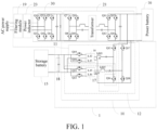
- the charging device in an embodiment of the present disclosure is illustrated below with reference to FIG. 1 .
- FIG. 1 is a schematic diagram of a charging device and connections thereof according to an embodiment of the present disclosure.
- a charging device 1 in this embodiment of the present disclosure includes a filtering module 19, a power factor correction (PFC) circuit module 30, and a second DC conversion module 21.
- a first terminal of the filtering module 19 is connected with an AC power supply.
- the PFC circuit module 30 is configured to perform a PFC on an inputAC and output a DC signal after the PFC.
- the PFC circuit module 30 includes at least three-phase bridge arms. Each phase bridge arm is connected with a second terminal of the filtering module 19 through a power inductor 23.
- An input terminal of the second DC conversion module 21 is connected with an output terminal of the PFC circuit module 30.
- An output terminal of the second DC conversion module 21 is connected with a power battery 16.
- the AC power supply enters the filtering module 19, the filtering module 19 filters the inputted AC power supply to filter out an excessive interference signal in the AC power supply, and the AC power supply after the filtering enters the PFC circuit module 30.
- the PFC circuit module 30 includes switching tubes Q1-Q6.
- the PFC circuit module 30 is configured to perform a PFC on the AC and output a DC signal.
- the DC signal enters the second DC conversion module 21.
- the second DC conversion module 21 includes devices such as switching tubes Q7-Q14 and a transformer. Based on the second DC conversion module 21, the DC signal is obtained, and DC conversion is performed on the DC signal, so as to provide a required DC signal for charging a storage battery.
- the charging device 1 in this embodiment of the present disclosure further includes a first DC conversion module 10 and a control module 20.
- the first DC conversion module 10 is configured to convert a DC signal outputted by the power battery 16 to a DC signal required for a storage battery 15.
- the DC signal charges the power battery 16 after DC conversion by the second DC conversion module 21.
- the power battery 16 outputs the DC signal.
- the first DC conversion module 10 converts the DC signal outputted by the power battery 16 to the DC signal required for the storage battery, to realize the charging of the storage battery 15.
- the first DC conversion module 10 includes a first half-bridge logical link control (LLC) circuit unit 11 and a second half-bridge LLC circuit unit 12 arranged in parallel.
- the control module 20 is connected with the first half-bridge LLC circuit unit 11 and the second half-bridge LLC circuit unit 12.
- the control module 20 is configured to acquire a total output current of the first DC conversion module 10 and control the first half-bridge LLC circuit unit 11 and the second half-bridge LLC circuit unit 12 to operate alternately when the total output current is less than a current threshold. That is to say, the control module 20 causes the two half-bridge LLC circuit units to operate alternately by monitoring the total output current based on the acquired total output current.
- an output current of the first half-bridge LLC circuit unit 11 is denoted as IoutM1
- an output current of the second half-bridge LLC circuit unit 12 is denoted as IoutM2
- the total output current of the first DC conversion module 10 is denoted as Iout
- a real-time temperature of the first half-bridge LLC circuit unit is denoted as T1
- a real-time temperature of the second half-bridge LLC circuit unit 12 is denoted as T2.
- the control module 20 controls operating states of the two half-bridge LLC circuit units based on the total output current Iout. That is, during the charging of the storage battery 15, the first half-bridge LLC circuit unit preferentially operates by default, and the total output current Iout is detected in real time.
- the control module 20 pre-stores a current threshold therein. When the total output current Iout is less than the current threshold, for example, Iout ⁇ Imax/2, the control module 20 controls the first half-bridge LLC circuit unit 11 and the second half-bridge LLC circuit unit 12 to operate alternately. During detection of the total output current of the two half-bridge LLC circuit units, the impact of a temperature on the two half-bridge LLC circuit units needs to be considered.
- the first half-bridge LLC circuit unit 11 and the second half-bridge LLC circuit unit 12 connected in parallel are arranged in the first DC conversion module 10.
- the control module 20 controls the operating states of the two half-bridge LLC circuit units based on the total output current of the first DC conversion module 10. When the total output current is less than the current threshold, the two half-bridge LLC circuit units are controlled to operate alternately. That is to say, the two half-bridge LLC circuit units operate at different times, which can prevent the whole half-bridge LLC circuit units from always being in the high frequency operating state, reduce the loss of the switching devices in the circuit unit, achieve temperature equilibrium, and improve the charging efficiency.
- the control module 20 when controlling the first half-bridge LLC circuit unit 11 and the second half-bridge LLC circuit unit 12 to operate alternately based on the total output current Iout, controls the operation of the first half-bridge LLC circuit unit 11 if the total output current Iout is detected to be less than the current threshold value Imax/2, and records a first operating time such as t1 of the first half-bridge LLC circuit unit 11.
- the first operating time t1 is compared with the time threshold such as S.
- the second half-bridge LLC circuit unit 12 is switched to operate, and a second operating time of the second half-bridge LLC circuit unit 12 is recorded, such as t2.
- the second operating time t2 is compared with the time threshold such as S.
- the first half-bridge LLC circuit unit is re-switched to operate.
- the two half-bridge LLC circuit units can operate alternately by cyclically performing the control process. As a result, the temperature of the two half-bridge LLC circuit units can maintain balance, avoid a temperature rise caused by a long-term operation of one half-bridge LLC circuit unit, and ensure the charging safety.
- the total output current Iout is continuously detected.
- the total output current Iout is different in size, and the control on the two half-bridge LLC circuit units is also different. For example, when the control module 20 detects that the total output current Iout is greater than or equal to the current threshold Imax/2, the first half-bridge LLC circuit unit 11 and the second half-bridge LLC circuit unit 12 are controlled to operate simultaneously. That is, the two half-bridge LLC circuit units are controlled to operate simultaneously, and the operating state of the two half-bridge LLC circuit units is controlled to ensure the charging effect by comparing the magnitude of the total output current Iout with the current threshold Imax/2.
- the control module 20 controls the first half-bridge LLC circuit unit 11 and the second half-bridge LLC circuit unit 12 to operate simultaneously, sets switching tube frequencies of the first half-bridge LLC circuit unit 11 and the second half-bridge LLC circuit unit 12, such as F, and is configured to interleave the switching tube of the first half-bridge LLC circuit unit 11 and the switching tube of the second half-bridge LLC circuit unit 12 at a preset phase angle difference.
- the switching tube of the first half-bridge LLC circuit unit 11 and the switching tube of the second half-bridge LLC circuit unit 12 operate alternately by 90° to reduce an output ripple current.
- the first half-bridge LLC circuit unit 11 includes a first switching tube Q15, a second switching tube Q16, a first capacitor C1, a first inductor IcM1, a first transformer 14, a third switching tube Q19, and a fourth switching tube Q20.
- a first terminal of the first switching tube Q15 is connected with a first terminal of the power battery 16.
- a second terminal of the first switching tube Q15 is connected with a first terminal of the second switching tube Q16.
- a control terminal of the first switching tube Q15 is connected with the control module 20.
- a second terminal of the second switching tube Q16 is connected with a second terminal of the power battery 16.
- a control terminal of the second switching tube Q16 is connected with the control module 20.
- a first node a is arranged between the second terminal of the first switching tube Q15 and the first terminal of the second switching tube Q16.
- the first half-bridge LLC circuit unit includes a first capacitor C1 and a first inductor IcM1.
- a first terminal of the first capacitor C1 is connected with the first node a; and a second terminal of the first capacitor C1 is connected with a first terminal of the first inductor IcM1.
- the first transformer 14 includes a first primary coil L11, a first secondary coil L12, and a second secondary coil L13.
- a first terminal of the first primary coil L11 is connected with a second terminal of the first inductor IcM1.
- a second terminal of the first primary coil L11 is connected with a second terminal of the second switching tube Q16.
- a second terminal of the first secondary coil L12 is connected with a first terminal of the second secondary coil L13 as a first common terminal; and the first common terminal is connected with a second terminal of the storage battery 15; and the first half-bridge LLC circuit unit includes a third switching tube Q19 and a fourth switching tube Q20.
- a first terminal of the third switching tube Q19 is connected with a first terminal of the first secondary coil L12; a second terminal of the third switching tube Q19 is connected with a first terminal of the storage battery 15; a control terminal of the third switching tube Q19 is connected with the control module 20; a first terminal of the fourth switching tube Q20 is connected with a second terminal of the second secondary coil L13; a second terminal of the fourth switching tube Q20 is connected with a second terminal of the third switching tube Q19 and a first terminal of the storage battery 15; and a control terminal of the fourth switching tube Q20 is connected with the control module 20.
- the control module 20 controls the switching state of each switching tube according to the magnitude of the total output current Iout of the first DC conversion module 10, so that the first half-bridge LLC circuit unit 11 and the second half-bridge LLC circuit unit 12 operate alternately.
- the first half-bridge LLC circuit unit 11 can avoid having each of the switching tubes always in operation when operating in different power ranges, and reduce the loss of the switching tube in the first half-bridge LLC circuit unit 11.
- the second half-bridge LLC circuit unit 12 includes a fifth switching tube Q17, a sixth switching tube Q18, a second capacitor C2, a second inductor IcM2, a second transformer 17, a seventh switching tube Q21, and an eighth switching tube Q22.
- a first terminal of the fifth switching tube Q17 is connected with a first terminal of the power battery 16.
- a second terminal of the fifth switching tube Q17 is connected with a first terminal of the sixth switching tube Q18.
- a control terminal of the fifth switching tube Q17 is connected with the control module 20.
- a second terminal of the sixth switching tube Q18 is connected with a second terminal of the power battery 16.
- a control terminal of the sixth switching tube Q18 is connected with the control module 20.
- a second node b is arranged between the second terminal of the fifth switching tube Q17 and the first terminal of the sixth switching tube Q18.
- Afirst terminal of the second capacitor C2 is connected with the second node b.
- a second terminal of the second capacitor C2 is connected with a first terminal of the second inductor IcM2.
- the second transformer 17 includes a second primary coil L14, a third secondary coil L15, and a fourth secondary coil L16.
- a first terminal of the second primary coil L14 is connected with a second terminal of the second inductor IcM2.
- a second terminal of the second primary coil L14 is respectively connected with the second terminal of the first transformer 14, the second terminal of the second switching tube Q16, and the second terminal of the sixth switching tube Q18.
- a second terminal of the third secondary coil L15 is connected with a first terminal of the fourth secondary coil L16 as a second common terminal.
- the second common terminal is connected with a second terminal of the storage battery 15.
- a first terminal of the seventh switching tube Q21 is connected with a first terminal of the third secondary coil L15.
- a second terminal of the seventh switching tube Q21 is connected with a first terminal of the storage battery 15.
- a control terminal of the seventh switching tube Q21 is connected with the control module 20.
- a first terminal of the eighth switching tube Q22 is connected with a second terminal of the fourth secondary coil L16.
- a second terminal of the eighth switching tube Q22 is connected with a second terminal of the seventh switching tube Q21 and a first terminal of the storage battery 15.
- a control terminal of the eighth switching tube Q22 is connected with the control module 20.
- the control module 20 controls the operating state of a master conversion unit M1 and a slave conversion unit M2 according to the magnitude of the current value of the total output current Iout received, so that a switching state of each switching tube is controlled and the first half-bridge LLC circuit unit 11 and the second half-bridge LLC circuit unit 12 operate alternately.
- the second half-bridge LLC circuit unit 12 can avoid having each of the switching tubes in operation when operating in different power ranges, and reduce the loss of the switching tube in the second half-bridge LLC circuit unit 12.
- the first DC conversion module 10 further includes a filtering unit 18.
- a first terminal of the filtering unit 18 is connected with a first terminal of the storage battery 15, and a second terminal of the filtering unit 18 is connected with a second terminal of the storage battery 15.
- the DC signal required by the storage battery is filtered by the filtering unit 18 to filter out an excess interference signal and improve the charging efficiency.
- the first half-bridge LLC circuit unit 11 and the second half-bridge LLC circuit unit 12 connected in parallel are arranged, and the control module 20 controls the operating state of the two half-bridge LLC circuit units based on the total output current of the first DC conversion module 10.
- the two half-bridge LLC circuit units are controlled to operate alternately. That is to say, the two half-bridge LLC circuit units do not operate at the same time, which can avoid the whole half-bridge LLC circuit unit from always operating at high frequency, reduce the loss of the switching devices in the circuit unit, and improve the charging efficiency.
- FIG. 3 is a block diagram of a vehicle according to an embodiment of the present disclosure.
- the vehicle 3 according to the embodiment of the present disclosure includes a storage battery 15, a power battery 16, and a charging device 1 mentioned in the above embodiment.
- the charging device 1 is respectively connected with the storage battery 15 and the power battery 16.
- the vehicle 3 according to the embodiment of the present disclosure uses the charging device 1 mentioned in the above embodiment to charge the vehicle 3, and control the two half-bridge LLC circuit units to operate alternately. That is to say, the two half-bridge LLC circuit units do not operate at the same time, which can avoid the whole half-bridge LLC circuit unit from always operating at high frequency, reduce the loss of the switching devices in the circuit unit, and improve the charging efficiency.
- the method for controlling charging of a charging device is described based on the charging device mentioned in the above embodiment.
- the charging device includes a first DC conversion module configured to convert a DC signal outputted by a power battery to a DC signal required for a storage battery.
- the first DC conversion module includes a first half-bridge LLC circuit unit and a second half-bridge LLC circuit unit arranged in parallel.
- FIG. 4 is a flowchart of a method for controlling charging of a charging device according to an embodiment of the present disclosure. As shown in FIG. 4 , the method of controlling charging of a charging device in this embodiment of the present disclosure includes at least step S1, step S2, and step S3.
- Step S1 A total output current of the first DC conversion module is acquired.
- the magnitude of the total output current is related to the operating state of the two half-bridge LLC circuit units.
- the power battery outputs the DC signal.
- the DC signal is passed through the first DC conversion module, the first DC conversion module converts the DC signal, and the controller acquires the total output current of the DC conversion module.
- Step S2 Whether the total output current is less than a current threshold is determined.
- a current threshold Imax/2 is pre-stored in the control module.
- the control module continuously detects the total output current Iout of the DC conversion module and compares the total output current Iout with the current threshold Imax/2 to determine the magnitude between the two current values.
- Step S3 The first half-bridge LLC circuit unit and the second half-bridge LLC circuit unit are controlled to operate alternately when the total output current is less than the current threshold.
- the magnitude of the total output current Iout and the current threshold Imax/2 determines the operating state of the first half-bridge LLC circuit unit and the second half-bridge LLC.
- the control module controls the two half-bridge LLC circuit units to operate alternately, which can avoid the two half-bridge LLC circuit units to always operate at high frequency and reduce the loss of switching devices in the circuit unit.
- the first half-bridge LLC circuit unit and said second half-bridge LLC circuit unit are controlled to operate alternatively based on the magnitude of the total output current and the current threshold. That is to say, the two half-bridge LLC circuit units do not operate at the same time, which can avoid the whole half-bridge LLC circuit unit from always operating at high frequency, reduce the loss of the switching devices in the circuit unit, and improve the charging efficiency.
- the control module controls the first half-bridge LLC circuit unit and the second half-bridge LLC circuit unit to operate alternately in cycles when the total output current Iout is less than the current threshold Imax/2.
- the control module detects that the total output current Iout is less than the current threshold Imax/2, the first half-bridge LLC circuit unit is controlled to operate and the first operating time t1 of the first half-bridge LLC circuit unit is recorded.
- the first operating time t1 is compared with the time threshold S.
- the second half-bridge LLC circuit unit is switched to operate, and a second operating time t2 of the second half-bridge LLC circuit unit is recorded.
- the second operating time t2 is compared with the time threshold S.
- the first half-bridge LLC circuit unit When the second operating time t2 reaches the time threshold S, the first half-bridge LLC circuit unit is re-switched to operate.
- the two half-bridge LLC circuit units can operate alternately by cyclically performing the control process. As a result, the temperature of the two half-bridge LLC circuit units can maintain balance, avoid a temperature rise caused by a long-term operation of one half-bridge LLC circuit unit, and ensure the charging safety.
- the first half-bridge LLC circuit unit and the second half-bridge LLC circuit unit are controlled to operate simultaneously.
- the operating state of the two half-bridge LLC circuit units is controlled, and the charging effect is better.
- the control module controls the first half-bridge LLC circuit unit and the second half-bridge LLC circuit unit to operate, and sets switching tube frequencies of the first half-bridge LLC circuit unit and the second half-bridge LLC circuit unit, such as F.
- the switching tube of the first half-bridge LLC circuit unit and the switching tube of the second half-bridge LLC circuit unit are staggered 90° apart to achieve a purpose of reducing an output ripple current.
- FIG. 5 is a flowchart of a method for controlling charging of a charging device according to an embodiment of the present disclosure.
- Step S11 The charging device is initially powered on.
- Step S12 A first half-bridge LLC circuit unit starts operating.
- Step S13 Whether a total output current is less than a current threshold is determined. If so, step S14 is performed, and if not, step S15 is performed.
- Step S14 The first half-bridge LLC circuit unit is controlled to operate and a first operating time of the first half-bridge LLC circuit unit is recorded.
- Step S15 The first half-bridge LLC circuit unit is controlled to operate and a second half-bridge LLC circuit unit is controlled to operate simultaneously.
- Step S16 Whether the first operating time exceeds the time threshold is determined. If so, step S17 is performed, and if not, step S16 is still performed.
- Step S17 The second half-bridge LLC circuit unit is switched to operate and a second operating time of the second half-bridge LLC circuit unit is recorded.
- Step S18 Whether the second operating time reaches the time threshold is determined. If so, step S19 is performed, and if not, step S18 is still performed.
- Step S19 The first half-bridge LLC circuit unit is switched to operate.
- the first half-bridge LLC circuit unit and said second half-bridge LLC circuit unit are controlled to operate alternatively based on the magnitude of the total output current and the current threshold. That is to say, the two half-bridge LLC circuit units do not operate at the same time, which can avoid the whole half-bridge LLC circuit unit from always operating at high frequency, reduce the loss of the switching devices in the circuit unit, and improve the charging efficiency.
Landscapes
- Engineering & Computer Science (AREA)
- Power Engineering (AREA)
- Transportation (AREA)
- Mechanical Engineering (AREA)
- Dc-Dc Converters (AREA)
- Charge And Discharge Circuits For Batteries Or The Like (AREA)
- Electric Propulsion And Braking For Vehicles (AREA)
Abstract
Description
- The present disclosure claims priority to
Chinese Patent Application No. 202011091549.8 filed on October 13, 2020 - The present disclosure relates to the field of vehicle technologies, and more specifically, to a charging device, a method for controlling charging of a charging device, and a vehicle.
- As vehicle commercialization progresses, a direct current-direct current (DC-DC) converter and an on-board charger (OBC) become vital components of vehicles.
- In response to an increasing charging demand and a demand for an increasingly short charging time, a high-power charging device is produced. In some high-power charging devices, the DC-DC converter includes two half-bridge logical link control (LLC) resonant circuits with a parallel output voltage of 13.8 V, to supply power to a storage battery and a low-voltage appliance.
- However, since an operating power range of the DC-DC converter varies between 0 W and 2500 W, a switch device thereof is always in a high frequency operating state, which causes high switching losses and affects the efficiency.
- The present disclosure is intended to resolve at least one of technical problems existing in the related art. One object of the present disclosure is to provide a charging device. The charging device can reduce the switching loss and improve the charging efficiency.
- A second objective of the present disclosure is to provide a vehicle.
- A third purpose of the present disclosure is intended to provide a method for controlling charging of a charging device.
- In order to achieve the foregoing objectives, an embodiment of a first aspect of the present disclosure provides a charging device. The charging device includes: a first DC conversion module, configured to convert a DC signal outputted by a power battery to a DC signal required for a storage battery, where the first DC conversion module includes a first half-bridge logical link control (LLC) circuit unit and a second half-bridge LLC circuit unit arranged in parallel; and a control module, connected with the first half-bridge LLC circuit unit and the second half-bridge LLC circuit unit and configured to acquire a total output current of the first DC conversion module, and control the first half-bridge LLC circuit unit and the second half-bridge LLC circuit unit to operate alternately when the total output current is less than a current threshold.
- According to the charging device in the embodiment of the present disclosure, the first half-bridge LLC circuit unit and the second half-bridge LLC circuit unit connected in parallel are arranged on the first DC conversion module. The control module controls the operating state of the two half-bridge LLC circuit units based on the total output current of the first DC conversion module. When the total output current is less than the current threshold, the two half-bridge LLC circuit units are controlled to operate alternately. That is to say, the two half-bridge LLC circuit units do not operate at the same time, which can avoid a switch the whole half-bridge LLC circuit unit from always operating at high frequency, reduce the loss of the switching devices in the circuit unit, and improve the charging efficiency.
- In some embodiments, the control module is configured to cyclically perform the following process when the first half-bridge LLC circuit unit and the second half-bridge LLC circuit unit operate alternately: controlling the first half-bridge LLC circuit unit to operate, recording a first operating time of the first half-bridge LLC circuit unit, switching the second half-bridge LLC circuit unit to operate when the first operating time reaches a time threshold, recording a second operating time of the second half-bridge LLC circuit unit, and switching the first half-bridge LLC circuit unit to operate when the second operating time reaches the time threshold. The two half-bridge LLC circuit units can operate alternately by cyclically performing the control process. As a result, the temperature of the two half-bridge LLC circuit units can maintain balance, avoid a temperature rise caused by a long-term operation of one half-bridge LLC circuit unit, and ensure the charging safety.
- In some embodiments, the control module is further configured to control the first half-bridge LLC circuit unit and the second half-bridge LLC circuit unit to operate simultaneously when the total output current is greater than or equal to the current threshold. By comparing the total output current with the current threshold, the operating state of the two half-bridge LLC circuit units is controlled when there is a large current output, and the charging effect is better.
- In some embodiments, the control module is configured to control a switching tube of the first half-bridge LLC circuit unit and a switching tube of the second half-bridge LLC circuit unit alternatively at a preset phase angle difference during control of the first half-bridge LLC circuit unit and the second half-bridge LLC circuit unit to operate simultaneously. When large current is outputted, the output ripple current can be reduced by controlling the switching tube of the first half-bridge LLC circuit unit and the switching tube of the second half-bridge LLC circuit unit to operate alternatively by a preset phase angle.
- In some embodiments, the first half-bridge LLC circuit unit includes: a first switching tube and a second switching tube, where a first terminal of the first switching tube is connected with a first terminal of the power battery; a second terminal of the first switching tube is connected with a first terminal of the second switching tube; a control terminal of the first switching tube is connected with the control module; a second terminal of the second switching tube is connected with a second terminal of the power battery; a control terminal of the second switching tube is connected with the control module; and a first node is arranged between the second terminal of the first switching tube and the first terminal of the second switching tube; a first capacitor and a first inductor, where a first terminal of the first capacitor is connected with the first node; and a second terminal of the first capacitor is connected with a first terminal of the first inductor; a first transformer, where the first transformer includes a first primary coil, a first secondary coil, and a second secondary coil; a first terminal of the first primary coil is connected with a second terminal of the first inductor; a second terminal of the first primary coil is connected with a second terminal of the second switching tube; a second terminal of the first secondary coil and a first terminal of the second secondary coil are connected as a first common terminal; and the first common terminal is connected with a second terminal of the storage battery; and a third switching tube and a fourth switching tube, where a first terminal of the third switching tube is connected with a first terminal of the first secondary coil; a second terminal of the third switching tube is connected with a first terminal of the storage battery; a control terminal of the third switching tube is connected with the control module; a first terminal of the fourth switching tube is connected with a second terminal of the second secondary coil; a second terminal of the fourth switching tube is connected with the second terminal of the third switching tube and the first terminal of the storage battery; and a control terminal of the fourth switching tube is connected with the control module. By controlling the two half-bridge LLC circuit units to operate separately, each switching tube is in the operating state, thus reducing the loss of the switching tubes in the half-bridge LLC circuit unit.
- In some embodiments, the second half-bridge LLC circuit unit includes: a fifth switching tube and a sixth switching tube, where a first terminal of the fifth switching tube is connected with the first terminal of the power battery; a second terminal of the fifth switching tube is connected with a first terminal of the sixth switching tube; a control terminal of the fifth switching tube is connected with the control module; a second terminal of the sixth switching tube is connected with the second terminal of the power battery; a control terminal of the sixth switching tube is connected with the control module; and a second node is arranged between the second terminal of the fifth switching tube and the first terminal of the sixth switching tube; a second capacitor and a second inductor, where a first terminal of the second capacitor is connected with the second node; and a second terminal of the second capacitor is connected with a first terminal of the second inductor; a second transformer, where the second transformer includes a second primary coil, a third secondary coil, and a fourth secondary coil; a first terminal of the second primary coil is connected with a second terminal of the second inductor; a second terminal of the second primary coil is connected with a second terminal of the first transformer, the second terminal of the second switching tube, and the second terminal of the sixth switching tube; a second terminal of the third secondary coil and a first terminal of the fourth secondary coil are connected as a second common terminal; and the second common terminal is connected with the second terminal of the storage battery; and a seventh switching tube and an eighth switching tube, where a first terminal of the seventh switching tube is connected with a first terminal of the third secondary coil; a second terminal of the seventh switching tube is connected with the first terminal of the storage battery; a control terminal of the seventh switching tube is connected with the control module; a first terminal of the eighth switching tube is connected with a second terminal of the fourth secondary coil; a second terminal of the eighth switching tube is connected with a second terminal of the seventh switching tube and the first terminal of the storage battery; and a control terminal of the eighth switching tube is connected with the control module. By controlling the two half-bridge LLC circuit units to operate separately, each switching tube is in the operating state, thus reducing the loss of the switching tubes in the half-bridge LLC circuit unit.
- In some embodiments, the first DC conversion module further includes a filtering unit, where a first terminal of the filtering unit is connected with a first terminal of the storage battery; and a second terminal of the filtering unit is connected with a second terminal of the storage battery.
- In some embodiments, the charging device further includes: a filtering module, where a first terminal of the filtering module is connected with an AC power supply; a power factor correction (PFC) circuit module, configured to perform a PFC on an input AC and output a DC signal after the PFC, where the PFC circuit module includes at least three-phase bridge arms; and each phase bridge arm is connected with a second terminal of the filtering module through a power inductor; and a second DC conversion module, where an input terminal of the second DC conversion module is connected with an output terminal of the PFC circuit module; and an output terminal of the second DC conversion module is connected with the power battery.
- In order to achieve the above purposes, an embodiment of a second aspect of the present disclosure provides a vehicle. The vehicle includes: a storage battery, a power battery, and the charging device according to the foregoing embodiment, where the charging device is respectively connected with the storage battery and the power battery.
- The vehicle according to the embodiment of the present disclosure uses the charging device mentioned in the above embodiment to charge the vehicle, and control the two half-bridge LLC circuit units to operate alternately. That is to say, the two half-bridge LLC circuit units do not operate at the same time, which can avoid the switch of whole half-bridge LLC circuit unit from always operating at high frequency, reduce the loss of the switching devices in the circuit unit, and improve the charging efficiency.
- In order to achieve the foregoing objectives, an embodiment of a third aspect of the present disclosure provides a method for controlling charging of a charging device. The charging device includes a first DC conversion module configured to convert a DC signal outputted by a power battery to a DC signal required for a storage battery; the first DC conversion module includes a first half-bridge LLC circuit unit and a second half-bridge LLC circuit unit arranged in parallel; and the method includes: acquiring a total output current of the first DC conversion module; determining whether the total output current is less than a current threshold; and controlling the first half-bridge LLC circuit unit and the second half-bridge LLC circuit unit to operate alternately when the total output current is less than the current threshold.
- According to the method for controlling charging of a charging device in the embodiment of the present disclosure, the first half-bridge LLC circuit unit and said second half-bridge LLC circuit unit are controlled to operate alternatively based on the magnitude of the total output current and the current threshold. That is to say, the two half-bridge LLC circuit units do not operate at the same time, which can avoid the switch of the whole half-bridge LLC circuit unit from always operating at high frequency, reduce the loss of the switching devices in the circuit unit, and improve the charging efficiency.
- In some embodiments, the controlling the first half-bridge LLC circuit unit and the second half-bridge LLC circuit unit to operate alternately includes: cyclically performing the following process: controlling the first half-bridge LLC circuit unit to operate, recording a first operating time of the first half-bridge LLC circuit unit, switching the second half-bridge LLC circuit unit to operate when the first operating time reaches a time threshold, recording a second operating time of the second half-bridge LLC circuit unit, and switching the first half-bridge LLC circuit unit to operate when the second operating time reaches the time threshold.
- In some embodiments, the method further includes: controlling the first half-bridge LLC circuit unit and the second half-bridge LLC circuit unit to operate simultaneously when the total output current is greater than or equal to the current threshold.
- In some embodiments, the controlling the first half-bridge LLC circuit unit and the second half-bridge LLC circuit unit to operate simultaneously includes: configured to alternatively control a switching tube of the first half-bridge LLC circuit unit and a switching tube of the second half-bridge LLC circuit unit at a preset phase angle difference.
- The additional aspects and advantages of the present disclosure will be provided in the following description, some of which will become apparent from the following description or may be learned from practices of the present disclosure.
- The foregoing and/or additional aspects and advantages of the present disclosure will become apparent and comprehensible from the following descriptions of the embodiments with reference to the accompanying drawings.
-
FIG. 1 is a schematic diagram of a circuit of a charging device according to an embodiment of the present disclosure. -
FIG. 2 is a schematic diagram of a circuit of a charging device according to an embodiment of the present disclosure. -
FIG. 3 is a block diagram of a vehicle according to an embodiment of the present disclosure. -
FIG. 4 is a flowchart of a method for controlling charging of a charging device according to an embodiment of the present disclosure. -
FIG. 5 is a flowchart of a method for controlling charging of a charging device according to an embodiment of the present disclosure. - The embodiments of the present invention are described in detail below, and the embodiments described with reference to accompanying drawings are exemplary.
- The charging device in an embodiment of the present disclosure is illustrated below with reference to
FIG. 1 . -
FIG. 1 is a schematic diagram of a charging device and connections thereof according to an embodiment of the present disclosure. As shown inFIG. 1 , acharging device 1 in this embodiment of the present disclosure includes afiltering module 19, a power factor correction (PFC)circuit module 30, and a secondDC conversion module 21. A first terminal of thefiltering module 19 is connected with an AC power supply. ThePFC circuit module 30 is configured to perform a PFC on an inputAC and output a DC signal after the PFC. ThePFC circuit module 30 includes at least three-phase bridge arms. Each phase bridge arm is connected with a second terminal of thefiltering module 19 through apower inductor 23. An input terminal of the secondDC conversion module 21 is connected with an output terminal of thePFC circuit module 30. An output terminal of the secondDC conversion module 21 is connected with apower battery 16. - In an embodiment, when the
charging device 1 is charging a vehicle, the AC power supply enters thefiltering module 19, thefiltering module 19 filters the inputted AC power supply to filter out an excessive interference signal in the AC power supply, and the AC power supply after the filtering enters thePFC circuit module 30. ThePFC circuit module 30 includes switching tubes Q1-Q6. ThePFC circuit module 30 is configured to perform a PFC on the AC and output a DC signal. The DC signal enters the secondDC conversion module 21. The secondDC conversion module 21 includes devices such as switching tubes Q7-Q14 and a transformer. Based on the secondDC conversion module 21, the DC signal is obtained, and DC conversion is performed on the DC signal, so as to provide a required DC signal for charging a storage battery. - As shown in
FIG. 1 andFIG. 2 , the chargingdevice 1 in this embodiment of the present disclosure further includes a firstDC conversion module 10 and acontrol module 20. The firstDC conversion module 10 is configured to convert a DC signal outputted by thepower battery 16 to a DC signal required for astorage battery 15. - Specifically, the DC signal charges the
power battery 16 after DC conversion by the secondDC conversion module 21. During charging of the storage battery, thepower battery 16 outputs the DC signal. The firstDC conversion module 10 converts the DC signal outputted by thepower battery 16 to the DC signal required for the storage battery, to realize the charging of thestorage battery 15. - In this embodiment of the present disclosure, the first
DC conversion module 10 includes a first half-bridge logical link control (LLC)circuit unit 11 and a second half-bridgeLLC circuit unit 12 arranged in parallel. Thecontrol module 20 is connected with the first half-bridgeLLC circuit unit 11 and the second half-bridgeLLC circuit unit 12. Thecontrol module 20 is configured to acquire a total output current of the firstDC conversion module 10 and control the first half-bridgeLLC circuit unit 11 and the second half-bridgeLLC circuit unit 12 to operate alternately when the total output current is less than a current threshold. That is to say, thecontrol module 20 causes the two half-bridge LLC circuit units to operate alternately by monitoring the total output current based on the acquired total output current. - In an embodiment, as shown in
FIG. 2 , for example, an output current of the first half-bridgeLLC circuit unit 11 is denoted as IoutM1, an output current of the second half-bridgeLLC circuit unit 12 is denoted as IoutM2, the total output current of the firstDC conversion module 10 is denoted as Iout, a real-time temperature of the first half-bridge LLC circuit unit is denoted as T1, and a real-time temperature of the second half-bridgeLLC circuit unit 12 is denoted as T2. Thecontrol module 20 controls operating states of the two half-bridge LLC circuit units based on the total output current Iout. That is, during the charging of thestorage battery 15, the first half-bridge LLC circuit unit preferentially operates by default, and the total output current Iout is detected in real time. Thecontrol module 20 pre-stores a current threshold therein. When the total output current Iout is less than the current threshold, for example, Iout < Imax/2, thecontrol module 20 controls the first half-bridgeLLC circuit unit 11 and the second half-bridgeLLC circuit unit 12 to operate alternately. During detection of the total output current of the two half-bridge LLC circuit units, the impact of a temperature on the two half-bridge LLC circuit units needs to be considered. By switching the first half-bridgeLLC circuit unit 11 and the second half-bridgeLLC circuit unit 12 to operate alternately, switching devices of the two half-bridge LLC circuit units are prevented from always being in a high frequency operating state, so that the temperatures of the two half-bridge LLC circuit units are kept equilibrated, which reduces the loss of the switching devices in a switching unit and improves the charging efficiency. - According to the
charging device 1 in this embodiment of the present disclosure, the first half-bridgeLLC circuit unit 11 and the second half-bridgeLLC circuit unit 12 connected in parallel are arranged in the firstDC conversion module 10. Thecontrol module 20 controls the operating states of the two half-bridge LLC circuit units based on the total output current of the firstDC conversion module 10. When the total output current is less than the current threshold, the two half-bridge LLC circuit units are controlled to operate alternately. That is to say, the two half-bridge LLC circuit units operate at different times, which can prevent the whole half-bridge LLC circuit units from always being in the high frequency operating state, reduce the loss of the switching devices in the circuit unit, achieve temperature equilibrium, and improve the charging efficiency. - In some embodiments, as shown in
FIG. 2 , thecontrol module 20, when controlling the first half-bridgeLLC circuit unit 11 and the second half-bridgeLLC circuit unit 12 to operate alternately based on the total output current Iout, controls the operation of the first half-bridgeLLC circuit unit 11 if the total output current Iout is detected to be less than the current threshold value Imax/2, and records a first operating time such as t1 of the first half-bridgeLLC circuit unit 11. The first operating time t1 is compared with the time threshold such as S. When the first operating time t1 reaches the time threshold S, the second half-bridgeLLC circuit unit 12 is switched to operate, and a second operating time of the second half-bridgeLLC circuit unit 12 is recorded, such as t2. The second operating time t2 is compared with the time threshold such as S. When the second operating time t2 reaches the time threshold S, the first half-bridge LLC circuit unit is re-switched to operate. The two half-bridge LLC circuit units can operate alternately by cyclically performing the control process. As a result, the temperature of the two half-bridge LLC circuit units can maintain balance, avoid a temperature rise caused by a long-term operation of one half-bridge LLC circuit unit, and ensure the charging safety. - In some embodiments, since the total output current Iout is constantly changing, in order to ensure the charging efficiency, the total output current Iout is continuously detected. The total output current Iout is different in size, and the control on the two half-bridge LLC circuit units is also different. For example, when the
control module 20 detects that the total output current Iout is greater than or equal to the current threshold Imax/2, the first half-bridgeLLC circuit unit 11 and the second half-bridgeLLC circuit unit 12 are controlled to operate simultaneously. That is, the two half-bridge LLC circuit units are controlled to operate simultaneously, and the operating state of the two half-bridge LLC circuit units is controlled to ensure the charging effect by comparing the magnitude of the total output current Iout with the current threshold Imax/2. - In some embodiments, when the total output current Iout is greater than or equal to the current threshold Imax/2, that is, when the output current is large, the
control module 20 controls the first half-bridgeLLC circuit unit 11 and the second half-bridgeLLC circuit unit 12 to operate simultaneously, sets switching tube frequencies of the first half-bridgeLLC circuit unit 11 and the second half-bridgeLLC circuit unit 12, such as F, and is configured to interleave the switching tube of the first half-bridgeLLC circuit unit 11 and the switching tube of the second half-bridgeLLC circuit unit 12 at a preset phase angle difference. For example, the switching tube of the first half-bridgeLLC circuit unit 11 and the switching tube of the second half-bridgeLLC circuit unit 12 operate alternately by 90° to reduce an output ripple current. - In some embodiments, as shown in
FIG. 1 andFIG. 2 , the first half-bridgeLLC circuit unit 11 includes a first switching tube Q15, a second switching tube Q16, a first capacitor C1, a first inductor IcM1, afirst transformer 14, a third switching tube Q19, and a fourth switching tube Q20. A first terminal of the first switching tube Q15 is connected with a first terminal of thepower battery 16. A second terminal of the first switching tube Q15 is connected with a first terminal of the second switching tube Q16. A control terminal of the first switching tube Q15 is connected with thecontrol module 20. A second terminal of the second switching tube Q16 is connected with a second terminal of thepower battery 16. A control terminal of the second switching tube Q16 is connected with thecontrol module 20. A first node a is arranged between the second terminal of the first switching tube Q15 and the first terminal of the second switching tube Q16. The first half-bridge LLC circuit unit includes a first capacitor C1 and a first inductor IcM1. A first terminal of the first capacitor C1 is connected with the first node a; and a second terminal of the first capacitor C1 is connected with a first terminal of the first inductor IcM1. Thefirst transformer 14 includes a first primary coil L11, a first secondary coil L12, and a second secondary coil L13. A first terminal of the first primary coil L11 is connected with a second terminal of the first inductor IcM1. A second terminal of the first primary coil L11 is connected with a second terminal of the second switching tube Q16. A second terminal of the first secondary coil L12 is connected with a first terminal of the second secondary coil L13 as a first common terminal; and the first common terminal is connected with a second terminal of thestorage battery 15; and the first half-bridge LLC circuit unit includes a third switching tube Q19 and a fourth switching tube Q20. A first terminal of the third switching tube Q19 is connected with a first terminal of the first secondary coil L12; a second terminal of the third switching tube Q19 is connected with a first terminal of thestorage battery 15; a control terminal of the third switching tube Q19 is connected with thecontrol module 20; a first terminal of the fourth switching tube Q20 is connected with a second terminal of the second secondary coil L13; a second terminal of the fourth switching tube Q20 is connected with a second terminal of the third switching tube Q19 and a first terminal of thestorage battery 15; and a control terminal of the fourth switching tube Q20 is connected with thecontrol module 20. Thecontrol module 20 controls the switching state of each switching tube according to the magnitude of the total output current Iout of the firstDC conversion module 10, so that the first half-bridgeLLC circuit unit 11 and the second half-bridgeLLC circuit unit 12 operate alternately. Thereby, the first half-bridgeLLC circuit unit 11 can avoid having each of the switching tubes always in operation when operating in different power ranges, and reduce the loss of the switching tube in the first half-bridgeLLC circuit unit 11. - In some embodiments, as shown in
FIG. 2 , the second half-bridgeLLC circuit unit 12 includes a fifth switching tube Q17, a sixth switching tube Q18, a second capacitor C2, a second inductor IcM2, asecond transformer 17, a seventh switching tube Q21, and an eighth switching tube Q22. A first terminal of the fifth switching tube Q17 is connected with a first terminal of thepower battery 16. A second terminal of the fifth switching tube Q17 is connected with a first terminal of the sixth switching tube Q18. A control terminal of the fifth switching tube Q17 is connected with thecontrol module 20. A second terminal of the sixth switching tube Q18 is connected with a second terminal of thepower battery 16. A control terminal of the sixth switching tube Q18 is connected with thecontrol module 20. A second node b is arranged between the second terminal of the fifth switching tube Q17 and the first terminal of the sixth switching tube Q18. Afirst terminal of the second capacitor C2 is connected with the second node b. A second terminal of the second capacitor C2 is connected with a first terminal of the second inductor IcM2. Thesecond transformer 17 includes a second primary coil L14, a third secondary coil L15, and a fourth secondary coil L16. A first terminal of the second primary coil L14 is connected with a second terminal of the second inductor IcM2. A second terminal of the second primary coil L14 is respectively connected with the second terminal of thefirst transformer 14, the second terminal of the second switching tube Q16, and the second terminal of the sixth switching tube Q18. A second terminal of the third secondary coil L15 is connected with a first terminal of the fourth secondary coil L16 as a second common terminal. The second common terminal is connected with a second terminal of thestorage battery 15. A first terminal of the seventh switching tube Q21 is connected with a first terminal of the third secondary coil L15. A second terminal of the seventh switching tube Q21 is connected with a first terminal of thestorage battery 15. A control terminal of the seventh switching tube Q21 is connected with thecontrol module 20. A first terminal of the eighth switching tube Q22 is connected with a second terminal of the fourth secondary coil L16. A second terminal of the eighth switching tube Q22 is connected with a second terminal of the seventh switching tube Q21 and a first terminal of thestorage battery 15. A control terminal of the eighth switching tube Q22 is connected with thecontrol module 20. Thecontrol module 20 controls the operating state of a master conversion unit M1 and a slave conversion unit M2 according to the magnitude of the current value of the total output current Iout received, so that a switching state of each switching tube is controlled and the first half-bridgeLLC circuit unit 11 and the second half-bridgeLLC circuit unit 12 operate alternately. Thereby, the second half-bridgeLLC circuit unit 12 can avoid having each of the switching tubes in operation when operating in different power ranges, and reduce the loss of the switching tube in the second half-bridgeLLC circuit unit 12. - In some embodiments, as shown in
FIG. 2 , the firstDC conversion module 10 further includes afiltering unit 18. A first terminal of thefiltering unit 18 is connected with a first terminal of thestorage battery 15, and a second terminal of thefiltering unit 18 is connected with a second terminal of thestorage battery 15. When chargingdevice 1 charges, the DC signal required by the storage battery is filtered by thefiltering unit 18 to filter out an excess interference signal and improve the charging efficiency. - Based on the above, according to the
charging device 1 in the embodiment of the present disclosure, the first half-bridgeLLC circuit unit 11 and the second half-bridgeLLC circuit unit 12 connected in parallel are arranged, and thecontrol module 20 controls the operating state of the two half-bridge LLC circuit units based on the total output current of the firstDC conversion module 10. When the total output current is less than the current threshold, the two half-bridge LLC circuit units are controlled to operate alternately. That is to say, the two half-bridge LLC circuit units do not operate at the same time, which can avoid the whole half-bridge LLC circuit unit from always operating at high frequency, reduce the loss of the switching devices in the circuit unit, and improve the charging efficiency. - A vehicle in an embodiment of a second aspect of the present disclosure is described below with reference to the accompanying drawings.
-
FIG. 3 is a block diagram of a vehicle according to an embodiment of the present disclosure. As shown inFIG. 3 , thevehicle 3 according to the embodiment of the present disclosure includes astorage battery 15, apower battery 16, and acharging device 1 mentioned in the above embodiment. The chargingdevice 1 is respectively connected with thestorage battery 15 and thepower battery 16. - The
vehicle 3 according to the embodiment of the present disclosure uses thecharging device 1 mentioned in the above embodiment to charge thevehicle 3, and control the two half-bridge LLC circuit units to operate alternately. That is to say, the two half-bridge LLC circuit units do not operate at the same time, which can avoid the whole half-bridge LLC circuit unit from always operating at high frequency, reduce the loss of the switching devices in the circuit unit, and improve the charging efficiency. - The method for controlling charging of a charging device is described based on the charging device mentioned in the above embodiment. The charging device includes a first DC conversion module configured to convert a DC signal outputted by a power battery to a DC signal required for a storage battery. The first DC conversion module includes a first half-bridge LLC circuit unit and a second half-bridge LLC circuit unit arranged in parallel. By controlling the operating state of the two half-bridge LLC circuit units, the damage to the switching devices in the circuit is reduced and the influence on the efficiency is reduced.
- The method for controlling charging of a charging device according to an embodiment of a third aspect of the present disclosure is described below with reference to the accompanying drawings.
-
FIG. 4 is a flowchart of a method for controlling charging of a charging device according to an embodiment of the present disclosure. As shown inFIG. 4 , the method of controlling charging of a charging device in this embodiment of the present disclosure includes at least step S1, step S2, and step S3. - Step S1: A total output current of the first DC conversion module is acquired.
- In the embodiment, when the charging device charges the vehicle, the magnitude of the total output current is related to the operating state of the two half-bridge LLC circuit units. The power battery outputs the DC signal. The DC signal is passed through the first DC conversion module, the first DC conversion module converts the DC signal, and the controller acquires the total output current of the DC conversion module.
- Step S2: Whether the total output current is less than a current threshold is determined.
- In the embodiment, a current threshold Imax/2 is pre-stored in the control module. The control module continuously detects the total output current Iout of the DC conversion module and compares the total output current Iout with the current threshold Imax/2 to determine the magnitude between the two current values.
- Step S3: The first half-bridge LLC circuit unit and the second half-bridge LLC circuit unit are controlled to operate alternately when the total output current is less than the current threshold.
- In the embodiment, the magnitude of the total output current Iout and the current threshold Imax/2 determines the operating state of the first half-bridge LLC circuit unit and the second half-bridge LLC. When the total output current Iout is less than the current threshold Imax/2, the control module controls the two half-bridge LLC circuit units to operate alternately, which can avoid the two half-bridge LLC circuit units to always operate at high frequency and reduce the loss of switching devices in the circuit unit.
- According to the method for controlling charging of a charging device in the embodiment of the present disclosure, the first half-bridge LLC circuit unit and said second half-bridge LLC circuit unit are controlled to operate alternatively based on the magnitude of the total output current and the current threshold. That is to say, the two half-bridge LLC circuit units do not operate at the same time, which can avoid the whole half-bridge LLC circuit unit from always operating at high frequency, reduce the loss of the switching devices in the circuit unit, and improve the charging efficiency.
- In some embodiments, the control module controls the first half-bridge LLC circuit unit and the second half-bridge LLC circuit unit to operate alternately in cycles when the total output current Iout is less than the current threshold Imax/2. When the control module detects that the total output current Iout is less than the current threshold Imax/2, the first half-bridge LLC circuit unit is controlled to operate and the first operating time t1 of the first half-bridge LLC circuit unit is recorded. The first operating time t1 is compared with the time threshold S. When the first operating time t1 reaches the time threshold S, the second half-bridge LLC circuit unit is switched to operate, and a second operating time t2 of the second half-bridge LLC circuit unit is recorded. The second operating time t2 is compared with the time threshold S. When the second operating time t2 reaches the time threshold S, the first half-bridge LLC circuit unit is re-switched to operate. The two half-bridge LLC circuit units can operate alternately by cyclically performing the control process. As a result, the temperature of the two half-bridge LLC circuit units can maintain balance, avoid a temperature rise caused by a long-term operation of one half-bridge LLC circuit unit, and ensure the charging safety.
- In some embodiments, when the total output current Iout is greater than or equal to the current threshold Imax/2, the first half-bridge LLC circuit unit and the second half-bridge LLC circuit unit are controlled to operate simultaneously. By comparing the total output current Iout with the current threshold of Imax/2, the operating state of the two half-bridge LLC circuit units is controlled, and the charging effect is better.
- In some embodiments, when the output current is large, the control module controls the first half-bridge LLC circuit unit and the second half-bridge LLC circuit unit to operate, and sets switching tube frequencies of the first half-bridge LLC circuit unit and the second half-bridge LLC circuit unit, such as F. At the same time, the switching tube of the first half-bridge LLC circuit unit and the switching tube of the second half-bridge LLC circuit unit are staggered 90° apart to achieve a purpose of reducing an output ripple current.
- The method for controlling charging of a charging device according to an embodiment of the present disclosure is described below in conjunction with
FIG. 5 . - As shown in
FIG. 5, FIG. 5 is a flowchart of a method for controlling charging of a charging device according to an embodiment of the present disclosure. - Step S11: The charging device is initially powered on.
- Step S12: A first half-bridge LLC circuit unit starts operating.
- Step S13: Whether a total output current is less than a current threshold is determined. If so, step S14 is performed, and if not, step S15 is performed.
- Step S14: The first half-bridge LLC circuit unit is controlled to operate and a first operating time of the first half-bridge LLC circuit unit is recorded.
- Step S15: The first half-bridge LLC circuit unit is controlled to operate and a second half-bridge LLC circuit unit is controlled to operate simultaneously.
- Step S16: Whether the first operating time exceeds the time threshold is determined. If so, step S17 is performed, and if not, step S16 is still performed.
- Step S17: The second half-bridge LLC circuit unit is switched to operate and a second operating time of the second half-bridge LLC circuit unit is recorded.
- Step S18: Whether the second operating time reaches the time threshold is determined. If so, step S19 is performed, and if not, step S18 is still performed.
- Step S19: The first half-bridge LLC circuit unit is switched to operate.
- step S20: Switching frequencies of the first half-bridge LLC circuit unit and the second half-bridge LLC circuit unit are set.
- step S21: A switching tube of the first half-bridge LLC circuit unit and a switching tube of the second half-bridge LLC circuit unit are controlled to operate alternatively by a preset angle.
- Based on the above, according to the method for controlling charging of a charging device in the embodiment of the present disclosure, the first half-bridge LLC circuit unit and said second half-bridge LLC circuit unit are controlled to operate alternatively based on the magnitude of the total output current and the current threshold. That is to say, the two half-bridge LLC circuit units do not operate at the same time, which can avoid the whole half-bridge LLC circuit unit from always operating at high frequency, reduce the loss of the switching devices in the circuit unit, and improve the charging efficiency.
- In the description of this specification, the description of the reference terms such as "an embodiment", "some embodiments", "exemplary embodiments", "example", "specific example", or "some examples" means that the specific features, structures, materials or characteristics described with reference to the embodiment or example are included in at least one embodiment or example of the present disclosure. In this specification, exemplary descriptions of the foregoing terms do not necessarily refer to the same embodiment or example.
- Although the embodiments of the present disclosure have been shown and described, a person of ordinary skill in the art should understand that various changes, modifications, replacements and variations may be made to the embodiments without departing from the principles and spirit of the present disclosure, and the scope of the present disclosure is as defined by the appended claims and their equivalents.
Claims (10)
- A charging device, comprising:a first DC conversion module, configured to convert a DC signal outputted by a power battery to a DC signal required for a storage battery, wherein the first DC conversion module comprises a first half-bridge logical link control (LLC) circuit unit and a second half-bridge LLC circuit unit arranged in parallel; anda control module, connected with the first half-bridge LLC circuit unit and the second half-bridge LLC circuit unit and configured to acquire a total output current of the first DC conversion module, and control the first half-bridge LLC circuit unit and the second half-bridge LLC circuit unit to operate alternately when the total output current is less than a current threshold.
- The charging device according to claim 1, wherein
the control module is configured to cyclically perform the following process when the first half-bridge LLC circuit unit and the second half-bridge LLC circuit unit operate alternately: controlling the first half-bridge LLC circuit unit to operate, recording a first operating time of the first half-bridge LLC circuit unit, switching the second half-bridge LLC circuit unit to operate when the first operating time reaches a time threshold, recording a second operating time of the second half-bridge LLC circuit unit, and switching the first half-bridge LLC circuit unit to operate when the second operating time reaches the time threshold. - The charging device according to claim 1 or 2, wherein
the control module is further configured to control the first half-bridge LLC circuit unit and the second half-bridge LLC circuit unit to operate simultaneously when the total output current is greater than or equal to the current threshold. - The charging device according to any of claims 1 to 3, wherein
the control module is configured to control a switching tube of the first half-bridge LLC circuit unit and a switching tube of the second half-bridge LLC circuit unit alternatively at a preset phase angle difference during control of the first half-bridge LLC circuit unit and the second half-bridge LLC circuit unit to operate simultaneously. - The charging device according to claim 1, wherein the first half-bridge LLC circuit unit comprises:a first switching tube and a second switching tube, wherein a first terminal of the first switching tube is connected with a first terminal of the power battery; a second terminal of the first switching tube is connected with a first terminal of the second switching tube; a control terminal of the first switching tube is connected with the control module; a second terminal of the second switching tube is connected with a second terminal of the power battery; a control terminal of the second switching tube is connected with the control module; and a first node is arranged between the second terminal of the first switching tube and the first terminal of the second switching tube;a first capacitor and a first inductor, wherein a first terminal of the first capacitor is connected with the first node; and a second terminal of the first capacitor is connected with a first terminal of the first inductor;a first transformer, wherein the first transformer comprises a first primary coil, a first secondary coil, and a second secondary coil; a first terminal of the first primary coil is connected with a second terminal of the first inductor; a second terminal of the first primary coil is connected with a second terminal of the second switching tube; a second terminal of the first secondary coil and a first terminal of the second secondary coil are connected as a first common terminal; and the first common terminal is connected with a second terminal of the storage battery; anda third switching tube and a fourth switching tube, wherein a first terminal of the third switching tube is connected with a first terminal of the first secondary coil; a second terminal of the third switching tube is connected with a first terminal of the storage battery; a control terminal of the third switching tube is connected with the control module; a first terminal of the fourth switching tube is connected with a second terminal of the second secondary coil; a second terminal of the fourth switching tube is connected with the second terminal of the third switching tube and the first terminal of the storage battery; and a control terminal of the fourth switching tube is connected with the control module.
- The charging device according to claim 1 or 5, wherein the second half-bridge LLC circuit unit comprises:a fifth switching tube and a sixth switching tube, wherein a first terminal of the fifth switching tube is connected with the first terminal of the power battery; a second terminal of the fifth switching tube is connected with a first terminal of the sixth switching tube; a control terminal of the fifth switching tube is connected with the control module; a second terminal of the sixth switching tube is connected with the second terminal of the power battery; a control terminal of the sixth switching tube is connected with the control module; and a second node is arranged between the second terminal of the fifth switching tube and the first terminal of the sixth switching tube;a second capacitor and a second inductor, wherein a first terminal of the second capacitor is connected with the second node; and a second terminal of the second capacitor is connected with a first terminal of the second inductor;a second transformer, wherein the second transformer comprises a second primary coil, a third secondary coil, and a fourth secondary coil; a first terminal of the second primary coil is connected with a second terminal of the second inductor; a second terminal of the second primary coil is connected with a second terminal of the first transformer, the second terminal of the second switching tube, and the second terminal of the sixth switching tube; a second terminal of the third secondary coil and a first terminal of the fourth secondary coil are connected as a second common terminal; and the second common terminal is connected with the second terminal of the storage battery; anda seventh switching tube and an eighth switching tube, wherein a first terminal of the seventh switching tube is connected with a first terminal of the third secondary coil; a second terminal of the seventh switching tube is connected with the first terminal of the storage battery; a control terminal of the seventh switching tube is connected with the control module; a first terminal of the eighth switching tube is connected with a second terminal of the fourth secondary coil; a second terminal of the eighth switching tube is connected with a second terminal of the seventh switching tube and the first terminal of the storage battery; and a control terminal of the eighth switching tube is connected with the control module.
- The charging device according to claim 1, wherein the first DC conversion module further comprises a filtering unit; a first terminal of the filtering unit is connected with a first terminal of the storage battery; and a second terminal of the filtering unit is connected with a second terminal of the storage battery.
- The charging device according to claim 1, further comprising:
a filtering module, wherein a first terminal of the filtering module is connected with an AC power supply;a power factor correction (PFC) circuit module, configured to perform a PFC on an input AC and output a DC signal after the PFC, wherein the PFC circuit module comprises at least three-phase bridge arms; and each phase bridge arm is connected with a second terminal of the filtering module through a power inductor; anda second DC conversion module, wherein an input terminal of the second DC conversion module is connected with an output terminal of the PFC circuit module; and an output terminal of the second DC conversion module is connected with the power battery. - A vehicle, comprising:a storage battery and a power battery; andthe charging device according to any of claims 1 to 8, wherein the charging device is connected with the storage battery and the power battery.
- A method for controlling charging of a charging device, wherein the charging device comprises a first DC conversion module configured to convert a DC signal outputted by a power battery to a DC signal required for a storage battery; the first DC conversion module comprises a first half-bridge LLC circuit unit and a second half-bridge LLC circuit unit arranged in parallel; and the method comprises:acquiring a total output current of the first DC conversion module;determining whether the total output current is less than a current threshold; andcontrolling the first half-bridge LLC circuit unit and the second half-bridge LLC circuit unit to operate alternately when the total output current is less than the current threshold.
Applications Claiming Priority (2)
| Application Number | Priority Date | Filing Date | Title |
|---|---|---|---|
| CN202011091549.8A CN114362269B (en) | 2020-10-13 | 2020-10-13 | Charging device, method of controlling charging of charging device, and vehicle |
| PCT/CN2021/117465 WO2022078126A1 (en) | 2020-10-13 | 2021-09-09 | Charging apparatus, method for controlling charging of charging apparatus, and vehicle |
Publications (2)
| Publication Number | Publication Date |
|---|---|
| EP4216397A1 true EP4216397A1 (en) | 2023-07-26 |
| EP4216397A4 EP4216397A4 (en) | 2024-04-17 |
Family
ID=81090393
Family Applications (1)
| Application Number | Title | Priority Date | Filing Date |
|---|---|---|---|
| EP21879172.1A Pending EP4216397A4 (en) | 2020-10-13 | 2021-09-09 | CHARGING DEVICE, METHOD FOR CONTROLLING THE CHARGING OF A CHARGING DEVICE AND VEHICLE |
Country Status (5)
| Country | Link |
|---|---|
| US (1) | US20230261492A1 (en) |
| EP (1) | EP4216397A4 (en) |
| JP (1) | JP7690028B2 (en) |
| CN (1) | CN114362269B (en) |
| WO (1) | WO2022078126A1 (en) |
Families Citing this family (2)
| Publication number | Priority date | Publication date | Assignee | Title |
|---|---|---|---|---|
| CN114362270B (en) * | 2020-10-13 | 2024-09-10 | 比亚迪股份有限公司 | Charging device, method of controlling charging of charging device, and vehicle |
| CN116345881A (en) * | 2023-03-21 | 2023-06-27 | 深圳陆巡科技有限公司 | Control method, device and storage medium of interleaved parallel PFC circuit |
Family Cites Families (14)
| Publication number | Priority date | Publication date | Assignee | Title |
|---|---|---|---|---|
| CN100521492C (en) * | 2007-06-13 | 2009-07-29 | 艾默生网络能源有限公司 | A harmonic vibration converter |
| CN104170204B (en) * | 2012-05-11 | 2019-02-05 | 富士电机株式会社 | motor drive |
| ITMO20130315A1 (en) * | 2013-11-14 | 2015-05-15 | Meta System Spa | EQUIPMENT FOR RECHARGING BATTERIES OF ELECTRIC OR SIMILAR VEHICLES |
| GB2540750B (en) * | 2015-07-21 | 2019-04-17 | Dyson Technology Ltd | Power supply |
| CN107662498A (en) * | 2016-07-28 | 2018-02-06 | 比亚迪股份有限公司 | Electric automobile, the multifunctional vehicle mounted charger of electric automobile and its control method |
| FR3060230B1 (en) * | 2016-12-14 | 2019-01-25 | Renault S.A.S | METHOD FOR CONTROLLING AN ON-BOARD CHARGING DEVICE ON AN ELECTRIC OR HYBRID VEHICLE |
| CN106787653B (en) * | 2017-03-31 | 2019-07-12 | 华为技术有限公司 | A kind of drive control method and power circuit |
| US10079541B1 (en) * | 2017-05-23 | 2018-09-18 | Murata Manufacturing Co., Ltd. | Wide input, wide output, high efficiency, isolated DC-DC converter-battery charger |
| CN107276190B (en) * | 2017-05-27 | 2020-02-21 | 华为技术有限公司 | Method, device and equipment for generating light-load ripple |
| CN107658955B (en) * | 2017-10-31 | 2024-05-10 | 厦门远双科技有限公司 | Energy-saving and power-saving control device and control method for vehicle-mounted charger |
| CN108683337A (en) * | 2018-04-26 | 2018-10-19 | 同济大学 | Transformation system with multiple LLC half bridge resonants and current equalizing method |
| CN109510453A (en) * | 2018-12-11 | 2019-03-22 | 南京工程学院 | An EV on-board charger based on SiC power devices |
| CN111313679B (en) * | 2020-03-02 | 2021-10-08 | 上海瞻芯电子科技有限公司 | Power supply system and charging equipment |
| CN114362270B (en) * | 2020-10-13 | 2024-09-10 | 比亚迪股份有限公司 | Charging device, method of controlling charging of charging device, and vehicle |
-
2020
- 2020-10-13 CN CN202011091549.8A patent/CN114362269B/en active Active
-
2021
- 2021-09-09 JP JP2023522796A patent/JP7690028B2/en active Active
- 2021-09-09 WO PCT/CN2021/117465 patent/WO2022078126A1/en not_active Ceased
- 2021-09-09 EP EP21879172.1A patent/EP4216397A4/en active Pending
-
2023
- 2023-04-04 US US18/295,610 patent/US20230261492A1/en active Pending
Also Published As
| Publication number | Publication date |
|---|---|
| WO2022078126A1 (en) | 2022-04-21 |
| CN114362269B (en) | 2024-08-02 |
| CN114362269A (en) | 2022-04-15 |
| EP4216397A4 (en) | 2024-04-17 |
| JP7690028B2 (en) | 2025-06-09 |
| JP2023545172A (en) | 2023-10-26 |
| US20230261492A1 (en) | 2023-08-17 |
Similar Documents
| Publication | Publication Date | Title |
|---|---|---|
| US11865933B2 (en) | Vehicle and energy conversion device and power system thereof | |
| EP3787170A1 (en) | Dcdc converter, vehicle-mounted charger and electric vehicle | |
| US9912247B2 (en) | DC link module for reducing DC link capacitance | |
| US9024465B2 (en) | Uninterruptible power system | |
| US20190288547A1 (en) | Ac charging of an intelligent battery | |
| CN204304574U (en) | The vehicle-mounted quick charge device of a kind of electric automobile | |
| US20230261492A1 (en) | Charging device, method for controlling charging of charging device, and vehicle | |
| EP3622609A1 (en) | Modular medium voltage fast chargers | |
| JPH11215841A (en) | Power supply for vehicles | |
| WO2016101380A1 (en) | Semi-vehicle-mounted rapid charging method and charging device thereof for electric bus | |
| CN108270348B (en) | Direct-current output low-frequency ripple suppression circuit of digital charger and control method thereof | |
| CN109067192B (en) | Control circuit and device for wide-voltage input inverter welding and cutting power supply | |
| CN106786886B (en) | wireless charging system charging method based on load identification technology | |
| CN111313679B (en) | Power supply system and charging equipment | |
| CN115800461A (en) | Energy storage system, three-phase energy storage system and energy storage cabinet | |
| CN114583809A (en) | Portable energy storage bidirectional inversion charging system | |
| EP3754829B1 (en) | Llc circuit | |
| US20240227591A1 (en) | Method and system for charging control, and vehicle | |
| CN114362270B (en) | Charging device, method of controlling charging of charging device, and vehicle | |
| US12470126B2 (en) | Power system and circulating current suppression method thereof | |
| CN113659843B (en) | DCDC converter with low switching loss | |
| CN108263240B (en) | Vehicle-mounted charging device of electric automobile and charging method thereof | |
| CN120280977B (en) | Energy storage system and control method thereof | |
| US20260025068A1 (en) | Resonant converter and method for parameter calculation thereof | |
| CN221929640U (en) | Power control system |
Legal Events
| Date | Code | Title | Description |
|---|---|---|---|
| STAA | Information on the status of an ep patent application or granted ep patent |
Free format text: STATUS: THE INTERNATIONAL PUBLICATION HAS BEEN MADE |
|
| PUAI | Public reference made under article 153(3) epc to a published international application that has entered the european phase |
Free format text: ORIGINAL CODE: 0009012 |
|
| STAA | Information on the status of an ep patent application or granted ep patent |
Free format text: STATUS: REQUEST FOR EXAMINATION WAS MADE |
|
| 17P | Request for examination filed |
Effective date: 20230418 |
|
| AK | Designated contracting states |
Kind code of ref document: A1 Designated state(s): AL AT BE BG CH CY CZ DE DK EE ES FI FR GB GR HR HU IE IS IT LI LT LU LV MC MK MT NL NO PL PT RO RS SE SI SK SM TR |
|
| DAV | Request for validation of the european patent (deleted) | ||
| DAX | Request for extension of the european patent (deleted) | ||
| A4 | Supplementary search report drawn up and despatched |
Effective date: 20240315 |
|
| RIC1 | Information provided on ipc code assigned before grant |
Ipc: H02M 3/28 20060101ALN20240311BHEP Ipc: H02M 1/42 20070101ALN20240311BHEP Ipc: H02M 3/00 20060101ALI20240311BHEP Ipc: H02J 7/02 20160101ALI20240311BHEP Ipc: H02J 1/08 20060101ALI20240311BHEP Ipc: B60L 53/53 20190101ALI20240311BHEP Ipc: B60L 53/22 20190101ALI20240311BHEP Ipc: H02M 1/14 20060101ALI20240311BHEP Ipc: H02M 3/335 20060101ALI20240311BHEP Ipc: H02J 7/00 20060101AFI20240311BHEP |