EP4216177A1 - Dispositif de traitement d'image de système de détection de personne - Google Patents
Dispositif de traitement d'image de système de détection de personne Download PDFInfo
- Publication number
- EP4216177A1 EP4216177A1 EP23151714.5A EP23151714A EP4216177A1 EP 4216177 A1 EP4216177 A1 EP 4216177A1 EP 23151714 A EP23151714 A EP 23151714A EP 4216177 A1 EP4216177 A1 EP 4216177A1
- Authority
- EP
- European Patent Office
- Prior art keywords
- area
- person
- obstacle
- processing device
- image processing
- Prior art date
- Legal status (The legal status is an assumption and is not a legal conclusion. Google has not performed a legal analysis and makes no representation as to the accuracy of the status listed.)
- Pending
Links
- 238000001514 detection method Methods 0.000 title claims abstract description 97
- 238000000034 method Methods 0.000 claims abstract description 93
- 238000010586 diagram Methods 0.000 description 6
- 239000000284 extract Substances 0.000 description 6
- 238000003384 imaging method Methods 0.000 description 6
- 230000007423 decrease Effects 0.000 description 5
- 230000000694 effects Effects 0.000 description 5
- 238000006243 chemical reaction Methods 0.000 description 4
- 230000003287 optical effect Effects 0.000 description 4
- 238000000926 separation method Methods 0.000 description 3
- 238000004590 computer program Methods 0.000 description 2
- 238000013135 deep learning Methods 0.000 description 2
- 238000000605 extraction Methods 0.000 description 2
- 238000010801 machine learning Methods 0.000 description 2
- 230000004044 response Effects 0.000 description 2
- 238000010276 construction Methods 0.000 description 1
- 238000012886 linear function Methods 0.000 description 1
- 238000004519 manufacturing process Methods 0.000 description 1
- 210000002784 stomach Anatomy 0.000 description 1
Images


Classifications
-
- G—PHYSICS
- G06—COMPUTING; CALCULATING OR COUNTING
- G06T—IMAGE DATA PROCESSING OR GENERATION, IN GENERAL
- G06T7/00—Image analysis
- G06T7/10—Segmentation; Edge detection
- G06T7/11—Region-based segmentation
-
- G—PHYSICS
- G06—COMPUTING; CALCULATING OR COUNTING
- G06V—IMAGE OR VIDEO RECOGNITION OR UNDERSTANDING
- G06V40/00—Recognition of biometric, human-related or animal-related patterns in image or video data
- G06V40/10—Human or animal bodies, e.g. vehicle occupants or pedestrians; Body parts, e.g. hands
-
- G—PHYSICS
- G06—COMPUTING; CALCULATING OR COUNTING
- G06V—IMAGE OR VIDEO RECOGNITION OR UNDERSTANDING
- G06V20/00—Scenes; Scene-specific elements
- G06V20/50—Context or environment of the image
- G06V20/56—Context or environment of the image exterior to a vehicle by using sensors mounted on the vehicle
- G06V20/58—Recognition of moving objects or obstacles, e.g. vehicles or pedestrians; Recognition of traffic objects, e.g. traffic signs, traffic lights or roads
-
- G—PHYSICS
- G06—COMPUTING; CALCULATING OR COUNTING
- G06T—IMAGE DATA PROCESSING OR GENERATION, IN GENERAL
- G06T7/00—Image analysis
- G06T7/60—Analysis of geometric attributes
-
- G—PHYSICS
- G06—COMPUTING; CALCULATING OR COUNTING
- G06V—IMAGE OR VIDEO RECOGNITION OR UNDERSTANDING
- G06V10/00—Arrangements for image or video recognition or understanding
- G06V10/40—Extraction of image or video features
-
- G—PHYSICS
- G06—COMPUTING; CALCULATING OR COUNTING
- G06V—IMAGE OR VIDEO RECOGNITION OR UNDERSTANDING
- G06V10/00—Arrangements for image or video recognition or understanding
- G06V10/40—Extraction of image or video features
- G06V10/50—Extraction of image or video features by performing operations within image blocks; by using histograms, e.g. histogram of oriented gradients [HoG]; by summing image-intensity values; Projection analysis
-
- G—PHYSICS
- G06—COMPUTING; CALCULATING OR COUNTING
- G06V—IMAGE OR VIDEO RECOGNITION OR UNDERSTANDING
- G06V10/00—Arrangements for image or video recognition or understanding
- G06V10/70—Arrangements for image or video recognition or understanding using pattern recognition or machine learning
- G06V10/74—Image or video pattern matching; Proximity measures in feature spaces
- G06V10/75—Organisation of the matching processes, e.g. simultaneous or sequential comparisons of image or video features; Coarse-fine approaches, e.g. multi-scale approaches; using context analysis; Selection of dictionaries
- G06V10/759—Region-based matching
-
- G—PHYSICS
- G06—COMPUTING; CALCULATING OR COUNTING
- G06V—IMAGE OR VIDEO RECOGNITION OR UNDERSTANDING
- G06V10/00—Arrangements for image or video recognition or understanding
- G06V10/70—Arrangements for image or video recognition or understanding using pattern recognition or machine learning
- G06V10/74—Image or video pattern matching; Proximity measures in feature spaces
- G06V10/761—Proximity, similarity or dissimilarity measures
-
- G—PHYSICS
- G06—COMPUTING; CALCULATING OR COUNTING
- G06V—IMAGE OR VIDEO RECOGNITION OR UNDERSTANDING
- G06V10/00—Arrangements for image or video recognition or understanding
- G06V10/70—Arrangements for image or video recognition or understanding using pattern recognition or machine learning
- G06V10/87—Arrangements for image or video recognition or understanding using pattern recognition or machine learning using selection of the recognition techniques, e.g. of a classifier in a multiple classifier system
-
- G—PHYSICS
- G06—COMPUTING; CALCULATING OR COUNTING
- G06V—IMAGE OR VIDEO RECOGNITION OR UNDERSTANDING
- G06V40/00—Recognition of biometric, human-related or animal-related patterns in image or video data
- G06V40/10—Human or animal bodies, e.g. vehicle occupants or pedestrians; Body parts, e.g. hands
- G06V40/103—Static body considered as a whole, e.g. static pedestrian or occupant recognition
-
- G—PHYSICS
- G06—COMPUTING; CALCULATING OR COUNTING
- G06T—IMAGE DATA PROCESSING OR GENERATION, IN GENERAL
- G06T2207/00—Indexing scheme for image analysis or image enhancement
- G06T2207/30—Subject of image; Context of image processing
- G06T2207/30196—Human being; Person
-
- G—PHYSICS
- G06—COMPUTING; CALCULATING OR COUNTING
- G06T—IMAGE DATA PROCESSING OR GENERATION, IN GENERAL
- G06T2207/00—Indexing scheme for image analysis or image enhancement
- G06T2207/30—Subject of image; Context of image processing
- G06T2207/30248—Vehicle exterior or interior
- G06T2207/30252—Vehicle exterior; Vicinity of vehicle
- G06T2207/30261—Obstacle
Definitions
- the present invention relates to an image processing device of a person detection system.
- an obstacle detector for detecting an obstacle is mounted on a moving body such as a vehicle.
- an obstacle detector includes a camera and an image processing device.
- the image processing device obtains image data from the camera.
- the image processing device performs a person detection process for the image data.
- the person detection process is performed using HOG (Histogram of Oriented Gradients) features, for example.
- image data does not include a whole body of a person due to a part of a moving body appearing in an imaging range of a camera, for example.
- accuracy of person detection decreases when a person detection process is performed.
- an image processing device of a person detection system mounted on a moving body configured to: detect, in image data obtained from a camera, an area in which an obstacle appears; determine whether the area meets an upper body detection process condition that the obstacle in the area is distanced from a road surface within a predetermined range from the camera; perform an upper body detection process in which the area of the image data is compared with upper body comparison data to determine whether the obstacle in the area is a person, for the area that meets the upper body detection process condition; and perform a whole-body detection process in which the area of the image data is compared with whole-body comparison data to determine whether the obstacle in the area is a person, for the area that does not meet the upper body detection process condition.
- a forklift truck 10 serving as a moving body includes a vehicle body 11, driving wheels 12, steering wheels 13, and a cargo handling apparatus 17.
- the vehicle body 11 includes a head guard 14 and a counterweight 15.
- the head guard 14 is provided above a driver seat.
- the counterweight 15 is provided at a rear part of the vehicle body 11.
- the counterweight 15 is a member for balancing a cargo loaded in the cargo handling apparatus 17.
- the forklift truck 10 may be operated in response to an operation by an operator, may be operated automatically, or may be switchable between a manual operation and an automatic operation.
- the forklift truck 10 is an example of an industrial vehicle.
- the forklift truck 10 includes a controller 20, a driving motor M11, a drive controller 23 controlling the driving motor M11, and a rotational speed sensor 24.
- the controller 20 controls a drive operation and a cargo handling operation.
- the controller 20 includes a processor 21 and a memory 22.
- the processor 21 is a CPU (Central Process Unit), a GPU (Graphics Process Unit), a DSP (Digital Signal Processor), or the like.
- the memory 22 has a RAM (Random Access Memory) and a ROM (Read Only Memory).
- the memory 22 stores programs for operating the forklift truck 10.
- the memory 22 stores program codes or commands configured to cause the processor 21 to execute processes.
- the controller 20 may include a hardware circuit such as an ASIC (Application Specific Integrated Circuit), an FPGA (Field Programmable Gate Array), and the like.
- the controller 20, which is a process circuit, may include one or more processors for operating in accordance with the computer programs, one or more hardware circuits such as the ASIC and the FPGA, or a combination thereof.
- the controller 20 gives the drive controller 23 a command for a rotational speed of the driving motor M11 such that a vehicle speed of the forklift truck 10 reaches a target vehicle speed.
- the drive controller 23 of the present embodiment is a motor driver.
- the rotational speed sensor 24 outputs the rotational speed of the driving motor M11 to the drive controller 23.
- the drive controller 23 controls the driving motor M11 such that the rotational speed of the driving motor M11 matches the command.
- a person detection system 30 is mounted on the forklift truck 10.
- the person detection system 30 includes a stereo camera 31 serving as a camera, and an image processing device 41.
- the person detection system 30 detects a person that is present around the forklift truck 10.
- the person detection system 30 may detect, in addition to the person, an obstacle other than the person.
- the image processing device 41 is an image processing device of the person detection system 30.
- the stereo camera 31 is disposed such that a road surface on which the forklift truck 10 is traveling can be seen from above the forklift truck 10.
- the stereo camera 31 is disposed in the head guard 14, for example.
- the stereo camera 31 captures an image of a rear area of the forklift truck 10.
- a person detected by the person detection system 30 is a person behind the forklift truck 10.
- the stereo camera 31 captures an image within an imaging range defined by a horizontal angle of view and a vertical angle of view.
- the counterweight 15 is included in a range of the vertical angle of view.
- a part of the counterweight 15 that is a part of the forklift truck 10 is always included in the image captured by the stereo camera 31.
- the stereo camera 31 includes a first camera 32 and a second camera 33.
- the first camera 32 and the second camera 33 include cameras using a CCD image sensor and a CMOS image sensor.
- the first camera 32 and the second camera 33 are arranged such that their optical axes are parallel to each other.
- Image data obtained by capturing of the image by the first camera 32 is referred to as first image data
- image data obtained by capturing of the image by the second camera 33 is referred to as second image data.
- the image processing device 41 has a processor 42 such as a CPU, a GPU, or a DSP, and a memory 43 including a RAM and a ROM.
- the memory 43 stores various programs for detecting an obstacle from an image captured by the stereo camera 31.
- the memory 43 stores program codes or commands configured to cause the processor 42 to execute processes.
- the memory 43 which is a computer readable medium, includes any available medium that is accessible by a general-purpose computer or a dedicated computer.
- the image processing device 41 may include a hardware circuit such as an ASIC or an FPGA.
- the image processing device 41, which is a process circuit may include one or more processors for operating in accordance with the computer programs, one or more hardware circuits such as the ASIC and the FPGA, or a combination thereof.
- the memory 43 stores whole-body dictionary data D1.
- the whole-body dictionary data D1 is dictionary data for detecting a person.
- the whole-body dictionary data D1 is, for example, data of features extracted from a plurality of known image data in which the person appears.
- the whole-body dictionary data D1 of the present embodiment is dictionary data obtained from image data in which a whole body of the person appears.
- Examples of the features include HOG (Histograms of Oriented Gradients) features and CoHOG (Co-occurrence HOG) features.
- HOG features are used.
- the HOG features each correspond to a histogram of a gradient intensity in a gradient orientation of a pixel value of a cell in the image data.
- the cell is a local area having a predetermined size.
- the image data is divided into a plurality of cells. Then, for each cell, the histogram in the gradient orientation of the pixel value is calculated and normalized within a block that is a predetermined range around the cell. Thus, the HOG features can be obtained.
- the image processing device 41 includes an auxiliary memory, the auxiliary memory may store the whole-body dictionary data D1.
- the processor 42 executes the programs stored in the memory 43 to perform the obstacle detection process.
- the obstacle detection process is repeatedly performed at a predetermined control cycle.
- Step S1 the image processing device 41 obtains the first image data and the second image data each having the same frame, from an image captured by the stereo camera 31.
- Step S2 the image processing device 41 performs a stereo process to obtain a disparity image.
- the disparity image is an image in which a disparity [px] is associated with a pixel.
- the first image data and the second image data are compared with each other, and a difference in pixels between the first image data and the second image data is calculated for the same feature point in each of the first image data and the second image data, so that a disparity is obtained.
- the feature point corresponds to a point that is visually recognized as a border such as an edge of an obstacle.
- the feature point is detected from information of brightness, and the like.
- the image processing device 41 converts RGB into YCrCb using the RAM temporarily storing each of the first image data and the second image data.
- the image processing device 41 may perform a distortion correction, an edge enhancement process, and the like.
- the image processing device 41 performs a stereo process in which a disparity is obtained by comparing similarity between each pixel of the first image data and each pixel of the second image data.
- the disparity may be calculated for each pixel, or may be calculated using a block-matching algorithm.
- each of the first image data and the second image data is divided into a plurality of blocks including a plurality of pixels to calculate the disparity for each block.
- the image processing device 41 obtains the disparity image based on the first image data as a reference image and the second image data as a comparison image. For each pixel of the first image data, the image processing device 41 extracts one of pixels of the second image data that is most similar to one of pixels of the first image data. Then, the image processing device 41 calculates a difference in horizontal pixel counts between the one of pixels of the first image data and the one of pixels of the second image data that is most similar to the one of pixels of the first image data as a disparity, which obtains the disparity image in which the disparity is associated with each pixel of the first image data that is the reference image.
- the disparity image need not be displayed, and may be data in which the disparity is associated with each pixel of the disparity image.
- the image processing device 41 may perform a process in which a disparity of a road surface is removed from the disparity image.
- the image processing device 41 derives coordinates of feature points in a world coordinate system.
- the image processing device 41 derives coordinates of feature points in a camera coordinate system.
- the stereo camera 31 is defined as an original point.
- the camera coordinate system is a cartesian coordinate system consisting of three axes, a Z-axis corresponding to an optical axis, an X-axis and a Y-axis corresponding to two axes perpendicular to the optical axis, respectively.
- the coordinates of the feature points in the camera coordinate system are represented by a Z-coordinate Zc, an X-coordinate Xc, and Y-coordinate Yc in the camera coordinate system.
- Xc xp ⁇ x ′ ⁇ Zc f Equation 3
- Yc yp ⁇ y ′ ⁇ Zc f
- xp is defined as an X-coordinate of a feature point in the disparity image
- yp is defined as a Y-coordinate of the feature point in the disparity image
- d is defined as a disparity associated with the X-coordinate and the Y-coordinate of the feature point.
- the world coordinate system is a coordinate system in a real space and is a cartesian coordinate system consisting of three axes, an X-axis corresponding to an axis extending in a horizontal direction, specifically in a vehicle width direction of the forklift truck 10, a Y-axis corresponding to an axis extending in the horizontal direction, specifically in a direction perpendicular to the X-axis, and a Z-axis corresponding to an axis perpendicular to the X-axis and the Y-axis, in a state where the forklift truck 10 is positioned on a horizontal plane.
- the Y-axis in the world coordinate system is also an axis extending in a front-rear direction of the forklift truck 10 that is a traveling direction of the forklift truck 10.
- the Z-axis in the world coordinate system is also an axis extending in a vertical direction. Coordinates of a feature point in the world coordinate system are represented by an X-coordinate Xw, a Y-coordinate Yw, and a Z-coordinate Zw in the world coordinate system.
- the image processing device 41 uses the following equation 4 to perform a world coordinate conversion that is conversion from camera coordinates into world coordinates.
- the world coordinates are coordinates in the world coordinate system. Equation 4
- Xw Yw Zw 1 0 0 0 cos ⁇ ⁇ sin ⁇ 0 sin ⁇ cos ⁇ Xc Yc Zc + 0 0 H
- H in the equation (4) is a mounting height [mm] of the stereo camera 31 in the world coordinate system
- ⁇ is an angle obtained by adding 90° to an angle defined by the optical axes of the first camera 32 and the second camera 33 parallel to each other and the horizontal plane.
- an original point in the world coordinate system corresponds to coordinates in which the X-coordinate Xw and the Y-coordinate Yw represent a position of the stereo camera 31 and the Z-coordinate Zw represents the road surface.
- the position of the stereo camera 31 is an intermediate position between a lens of the first camera 32 and a lens of the second camera 33, for example.
- the X-coordinate Xw represents a distance from the original point to a feature point in the vehicle width direction of the forklift truck 10.
- the Y-coordinate Yw represents a distance from the original point to the feature point in the traveling direction of the forklift truck 10.
- the Z-coordinate Zw represents a height from the road surface to the feature point.
- the feature point is a point representing a part of an obstacle.
- a Y-axis in the following description is in the world coordinate system. In FIG. 1 , an arrow Y represents the Y-axis in the world coordinate system, an arrow Z represents a Z-axis in the world coordinate system.
- Step S4 the image processing device 41 extracts an obstacle existing in the world coordinate system.
- the image processing device 41 defines, as one point group, a set of feature points assumed to represent the same obstacle among the feature points representing a part of the obstacle, and extracts the one point group as the obstacle.
- the image processing device 41 performs clustering to define the feature points positioned within a predetermined range as one point group from the world coordinates of the feature points derived in Step S3.
- the image processing device 41 recognizes the clustered point group as one obstacle.
- the clustering of the feature points in Step S4 is performed by various methods. That is, the clustering may be performed by any method as long as the feature points are defined as one point group and thus recognized as the obstacle.
- Step S5 the image processing device 41 derives a position of the obstacle extracted in Step S4.
- the image processing device 41 recognizes world coordinates of the obstacle from the world coordinates of the feature points forming the clustered point group.
- An X-coordinate Xw, a Y-coordinate Yw, and a Z-coordinate Zw of each feature point located at an end of the clustered point group may correspond to those of the obstacle, or an X-coordinate Xw, a Y-coordinate Yw, and a Z-coordinate Zw of a feature point as a center of the point group may correspond to those of the obstacle, for example. That is, the coordinates of the obstacle in the world coordinate system may represent the entire obstacle or one point of the obstacle.
- Step S6 the image processing device 41 detects a position of the obstacle in the first image data.
- the position of the obstacle in the first image data may be detected from the disparity image.
- the position of the obstacle in the first image data are represented in an area indicating a range of the first image data.
- the area of the present embodiment is a rectangular area.
- the rectangular area is an area including the obstacle in the first image data.
- the image processing device 41 associates the rectangular area with world coordinates of the obstacle derived in Step S6. For example, the image processing device 41 converts from the world coordinates into camera coordinates of the obstacle, and converts from the camera coordinates of the obstacle into coordinates of the first image data.
- the world coordinates of the obstacle are associated with the rectangular area. That is, the image processing device 41 can obtain world coordinates of the rectangular area.
- a Z-coordinate Zw of the rectangular area represents a height of the rectangular area from the road surface. That is, the image processing device 41 detects the height of the rectangular area from the road surface.
- the height of the rectangular area from the road surface includes a height of a lower end of the rectangular area from the road surface and a height of an upper end of the rectangular area from the road surface.
- the position of the obstacle corresponds to a position in the world coordinate system, i.e., world coordinates, and also corresponds to a position of the rectangular area.
- the position of the obstacle in first image data is in an image coordinate system.
- the image coordinate system represents pixel positions of the first image data.
- an X-axis represents a horizontal direction
- a Y-axis represents a vertical direction.
- the position of the obstacle in the first image data also corresponds to a position of the rectangular area of the first image data.
- a Y-coordinate Yi represents the Y-coordinate in the image coordinate system, as appropriate.
- the image processing device 41 performs a person detection process for the rectangular area.
- rectangular areas B1, B2 are obtained by the obstacle detection process, as illustrated in FIG. 4 .
- first image data IM1 includes a person M1 whose whole body appears and a person M2 whose lower body is hidden by the counterweight 15.
- the Y-coordinate Yi of a lower end of each of the rectangular areas B1, B2 of the first image data IM1 represents the lowest part of the obstacle in the first image data IM1.
- the Y-coordinate Yi of an upper end of each of the rectangular areas B1, B2 of the first image data IM1 represents a top of the obstacle in the first image data IM1.
- the image processing device 41 determines whether the rectangular areas B1, B2 meet an upper body detection process condition.
- the upper body detection process condition is for determining whether the obstacle hidden by an obstruction such as the counterweight 15 appears in the first image data IM1.
- the upper body detection process condition is for classifying an obstacle that may be a person whose upper body appears in the first image data IM1 and whose lower body is hidden by the obstruction, and another obstacle other than the obstacle that is such a person.
- both a distance condition and a separation condition are met, the image processing device 41 determines that the rectangular areas B1, B2 meet the upper body detection process condition.
- the distance condition means that a distance from a rear end of the forklift truck 10 to an obstacle is within a predetermined range.
- the separation condition means that an obstacle is distanced from the road surface at a predetermined height or more.
- whether the distance condition is met is determined from a distance to the obstacle in a Y-axis direction.
- the distance to the obstacle is a distance from the rear end of the forklift truck 10 to a central position of each of the rectangular areas B1, B2 in the Y-axis direction.
- Adistance L1 from the stereo camera 31 to the rear end of the forklift truck 10 in the Y-axis direction is known.
- the memory 43 pre-stores the distance L1 from the stereo camera 31 to the rear end of the forklift truck 10 or the Y-coordinate Yw of the rear end of the forklift truck 10, so that the image processing device 41 derives a distance L2 from the rear end of the forklift truck 10 to the rectangular areas B1, B2 in the Y-axis direction. Then, when the distance L2 is within a predetermined distance, the image processing device 41 determines that the distance condition is met.
- the predetermined distance of the distance condition is set based on resolution of the stereo camera 31 and the whole-body dictionary data D1, for example. As the resolution of the stereo camera 31 increases, features to be obtained increases, which increases the predetermined distance.
- a distance from the obstacle to the stereo camera 31 increases, a size of the obstacle in the first image data IM1 is reduced. Therefore, a person detectable distance is changed depending on pixel counts of image data that is used when the whole-body dictionary data D1 is obtained.
- the predetermined distance may be changed depending on the person detectable distance.
- the Y-coordinate Yw of the obstacle represents a distance from the stereo camera 31 to the obstacle. Therefore, the distance condition determines whether the distance from the stereo camera 31 to the obstacle is within the predetermined range.
- Whether the separation condition is met is determined from the Z-coordinate Zw of the lower end of each of the rectangular areas B1, B2.
- An original point of the Z-coordinate Zw corresponds to the road surface.
- the Z-coordinate Zw of the lower end of each of the rectangular areas B1, B2 represents a height H1 at which the obstacle is distanced from the road surface.
- FIG. 1 when the obstacle is hidden by the counterweight 15, a lower part of the obstacle is a blind spot in an imaging range of the stereo camera 31.
- the obstacle seems to be distanced from the road surface.
- a predetermined height is set in accordance with a height of the stereo camera 31 and a position of the counterweight 15, for example.
- the predetermined height may be a height in a range hidden by the counterweight 15 when the obstacle exists within the predetermined distance.
- the predetermined height may be changed in accordance with the Y-coordinate Yw of each of the rectangular areas B1, B2. In this case, as the rectangular areas B1, B2 are distanced from the forklift truck 10, the predetermined height may be lowered.
- the upper body detection process condition means that the obstacle is distanced from the road surface within the predetermined range from the stereo camera 31.
- the rectangular area B1 does not meet the upper body detection process condition, and the rectangular area B2 meets the upper body detection process condition.
- Step S11 When a determination result in Step S11 is NO, that is, when the obstacle does not meet the upper body detection process condition, the image processing device 41 performs a process of Step S12.
- Step S12 using the rectangular area B1 as an example.
- Step S12 the image processing device 41 performs a whole-body detection process.
- the rectangular area B1 corresponding to the obstacle that does not meet the upper body detection process condition is compared with the whole-body dictionary data D1.
- the image processing device 41 extracts features of the rectangular area B1 by the same process as features extraction used for obtaining the whole-body dictionary data D1.
- HOG features are extracted from the rectangular area B1.
- person detection is performed based on machine learning and pattern matching between the HOG features extracted from the rectangular area B1 and the whole-body dictionary data D1 to determine whether the obstacle in the rectangular area B1 is a person.
- the image processing device 41 terminates the person detection process.
- the whole-body dictionary data D1 corresponds to whole-body comparison data.
- Step S11 when the determination result in Step S11 is YES, that is, when the obstacle meets the upper body detection process condition, the image processing device 41 performs an upper body detection process S20.
- the upper body detection process S20 includes Step S21 and Step S22. The following will describe the upper body detection process S20 using the rectangular area B2 as an example.
- the image processing device 41 corrects a height of the rectangular area B2 of the first image data IM1. Specifically, the image processing device 41 corrects a position of the lower end of the rectangular area B2 in the first image data IM1, and takes out a part of the rectangular area B2 from the rectangular area B2 by a predetermined length from the upper end toward the lower end of the rectangular area B2. When the obstacle in the rectangular area B2 is a person, the image processing device 41 corrects the rectangular area B2 such that the lower end of the rectangular area B2 of the first image data IM1 corresponds to a position of a chest of the person.
- the upper end of the rectangular area B2 of the first image data IM1 corresponds to a position of a top of head of the person.
- a dimension of the rectangular area B2 in the Y-axis direction in the image coordinate system, that is, a height of the rectangular area B2 of the first image data IM1 is corrected so as to correspond to a range from the chest to the top of head of the person.
- the range from the chest to the top of head of the person varies depending on a height of the person. The taller the person, the greater the range from the chest to the top of head of the person.
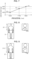
- the chest is positioned 600 [mm] below the top of head.
- the chest is positioned 540 [mm] below the top of head.
- the chest is positioned 430 [mm] below the top of head.
- a general position of the chest can be recognized by the height of the person, and thus, the height of the rectangular area B2 is corrected in accordance with a position of the top of head of the person.
- the height of the upper end of the rectangular area B2 and a correction amount are associated with each other.
- the correction amount indicates a range of the rectangular area B2 in the world coordinate system from the reference point toward the lower end of the rectangular area B2.
- the correction amount is 600 [mm].
- a height of the lower end of the rectangular area B2 is 1250 [mm], which is positioned 600 [mm] below from the height of the upper end of the rectangular area B2 that is 1850 [mm].
- a range of the rectangular area B2 in the world coordinate system is from 1850 [mm] to 1250 [mm].
- three reference points P1 to P3 are each set for the height of the upper end of the rectangular area B2 and associated with a correction amount.
- the three reference points P1 to P3 correspond to a first reference point P1, a second reference point P2, and a third reference point P3, respectively.
- the first reference point P1 is 1850 [mm].
- the second reference point P2 is 1700 [mm].
- the third reference point P3 is 1500 [mm]. 600 [mm] as the correction amount is associated with the first reference point P1.
- 540 [mm] as the correction amount is associated with the second reference point P2.
- 430 [mm] as the correction amount is associated with the third reference point P3.
- the image processing device 41 derives the correction amount from the Z-coordinate Zw of the upper end of the rectangular area B2.
- the Z-coordinate Zw of the upper end of the rectangular area B2 is a height corresponding to each of the reference points P1 to P3
- the image processing device 41 derives a value associated with each of the reference points P1 to P3 as the correction amount.
- the image processing device 41 derives 600 [mm] as the correction amount.
- the image processing device 41 derives the correction amount from a value associated with each of the reference points P1 to P3. For example, when the Z-coordinate Zw of the upper end of the rectangular area B2 is 1600 [mm], the image processing device 41 derives the correction amount based on a value associated with the second reference point P2 and a value associated with the third reference point P3. For example, the image processing device 41 only needs to derive the correction amount corresponding to 1600 [mm] from a linear function represented by the second reference point P2, the third reference point P3, the value associated with the second reference point P2, and the value associated with the third reference point P3.
- the image processing device 41 When the Z-coordinate Zw of the upper end of the rectangular area B2 corresponds to a height higher than the first reference point P1, the image processing device 41 derives a value associated with the first reference point P1 as the correction amount. When the Z-coordinate Zw of the upper end of the rectangular area B2 corresponds to a height lower than the third reference point P3, the image processing device 41 derives a value associated with the third reference point P3 as the correction amount.
- the image processing device 41 uses the derived correction amount to correct the height of the lower end of the rectangular area B2.
- the image processing device 41 sets the height of the lower end of the rectangular area B2 at a position obtained by subtracting the correction amount from the height of the upper end of the rectangular area B2. As described above, when the height of the upper end of the rectangular area B2 is 1850 [mm], the height of the lower end of the rectangular area B2 is 1250 [mm] obtained by subtracting 600 [mm] from 1850 [mm].
- the image processing device 41 derives the Y-coordinate Yi of the lower end of the rectangular area B2 of the first image data IM1 from the height of the lower end of the rectangular area B2 obtained by the correction amount.
- the image processing device 41 uses the Z-coordinate Zw corresponding to the height of the lower end of the rectangular area B2 obtained by the correction amount to derive camera coordinates of the lower end of the rectangular area B2 obtained by the correction amount.
- the camera coordinates are converted into coordinates of the first image data IM1, which derives the Y-coordinate Yi of the lower end of the rectangular area B2 of the first image data IM1.
- the Y-coordinate Yi of the lower end of the rectangular area B2 of the first image data IM1 is corrected to a position indicated by a dashed-dotted line.
- the rectangular area B2 in which the position of the lower end of the rectangular area B2 of the first image data IM1 is corrected may be referred to as a post-correction area B22.
- a dimension L3 of the post-correction area B22 in the Y-axis direction in the image coordinate system is smaller than a dimension L4 of the rectangular area B2 in the Y-axis direction in the image coordinate system.
- the post-correction area B22 of the first image data IM1 is a part of the rectangular area B2 taken out from the rectangular area B2 by a predetermined length from the upper end toward the lower end of the rectangular area B2.
- the predetermined length has a value obtained by converting the correction amount into a dimension in the image coordinate system.
- Step S21 is a process in which a part of the rectangular area B2 is taken out from the rectangular area B2 by the predetermined length from the upper end toward the lower end of the rectangular area B2 of the first image data IM1.
- Step S22 the image processing device 41 compares the post-correction area B22 with the whole-body dictionary data D1.
- comparison of the post-correction area B22 with the whole-body dictionary data D1 is performed using an area D11 representing a part of the whole-body dictionary data D1 above a position corresponding to the chest of the person. That is, the comparison is performed using the area D11 representing a part of the whole-body dictionary data D1, which is obtained from the image data in which a whole body of a person appears, corresponding to the post-correction area B22.
- the area D11 serves as upper body comparison data.
- the image processing device 41 extracts features of the post-correction area B22 by the same process as features extraction used for obtaining the whole-body dictionary data D1.
- HOG features are extracted from the post-correction area B22.
- person detection is performed based on machine learning and pattern matching between the HOG features extracted from the post-correction area B22 and the area D11 to determine whether the obstacle in the rectangular area B2 is a person.
- Step S22 is a process in which the post-correction area B22 of the first image data IM1 taken out from the rectangular area B2 is compared with the area D11 to determine whether the obstacle in the rectangular area B2 is a person. After the determination of Step S22, the image processing device 41 terminates the upper body detection process S20 and the person detection process.
- the position of the person existing around the forklift truck 10 is detected by the person detection process.
- the position of the person is outputted to the controller 20.
- the controller 20 may control the forklift truck 10 in accordance with the position of the person. For example, when a person exists within a predetermined range from the forklift truck 10, the controller 20 may limit a vehicle speed and may allow an alarm device to issue an alarm. The alarm may be issued to a person around the forklift truck 10, or a passenger of the forklift truck 10.
- the image processing device 41 extracts the rectangular areas B1, B2 in which the obstacle appears, from the first image data IM1, and determines whether the obstacle is separated from the road surface in each of the rectangular areas B1, B2.
- the rectangular areas B1, B2 including the obstacle meet the upper body detection process condition.
- the obstacle is separated from the road surface and is a person, the upper body of the person may appear in the first image data IM1.
- the image processing device 41 performs, for the rectangular area B2 that meets the upper body detection process condition, the upper body detection process in which the rectangular area B2 is compared with the area D11 to determine whether the obstacle in the rectangular area B2 is a person.
- the counterweight 15 is an example of the obstruction
- the obstruction may be any object other than the counterweight 15. Even in this case, the same effect is obtained by the same control as in the above-described embodiment.
- the lower body of the person is not hidden by the obstruction and is positioned below the imaging range of the stereo camera 31, only the upper body of the person appears in the first image data IM1. Even in this case, the same effect is obtained by the same control as in the above-described embodiment.
- the image processing device 41 need not correct the height of the rectangular area B2.
- the image processing device 41 need not derive the post-correction area B22 from the rectangular area B2.
- the image processing device 41 may perform a process in which an area ratio is detected, instead of correction of the height of the rectangular area B2.
- the area ratio means a ratio of a dimension of the rectangular area B2 from the lower end to the upper end of the rectangular area B2 to the height of a top of the obstacle.
- the height of the top of the obstacle is obtained from the Z-coordinate Zw of the upper end of the rectangular area B2.
- the area ratio is obtained by dividing a dimension between the Z-coordinate Zw of the upper end of the rectangular area B2 and the Z-coordinate Zw of the lower end of the rectangular area B2 by a height corresponding to the Z-coordinate Zw of the upper end of the rectangular area B2.
- the image processing device 41 detects the area ratio based on the height of the lower end of the rectangular area B2 from the road surface and the height of the upper end of the rectangular area B2 from the road surface. That is, Step S21 of the modified embodiment is the process in which an area ratio is detected based on the height of the lower end of the rectangular area B2 from the road surface and the height of the upper end of the rectangular area B2 from the road surface.
- Step S22 included in the upper body detection process S20 the image processing device 41 performs a process in which an area D12 obtained by applying the area ratio to the whole-body dictionary data D1 is compared with the rectangular area B2.
- Applying the area ratio to the whole-body dictionary data D1 means that an area in a direction from the upper end toward the lower end of the whole-body dictionary data D1 corresponding to the area ratio is taken out.
- the area D12 serves as upper body comparison data.
- the image processing device 41 compares the area D12 with the rectangular area B2 to detect a person.
- Step S22 of the modified embodiment is the process in which the area D12 obtained by applying the area ratio to the whole-body dictionary data D1 is compared with the rectangular area B2 of the image data to determine whether the obstacle in the rectangular area B2 is a person.
- the same effect as that in the above-described embodiment is obtained.
- the memory 43 may store the whole-body dictionary data D1 and the upper body dictionary data D2.
- the upper body dictionary data D2 corresponds to dictionary data of the features extracted from the image data in which the upper body of the person appears.
- the whole-body dictionary data D1 is used to detect a person.
- the upper body dictionary data D2 is used to detect a person.
- the upper body dictionary data D2 corresponds to upper body comparison data.
- the distance condition may be a condition in which a distance to the obstacle is within a predetermined distance from the stereo camera 31.
- the predetermined distance of the modified embodiment is simply required to correspond to a length in which the distance L1 is added to the predetermined distance of the above-described embodiment.
- the image processing device 41 may correct the rectangular area B2 such that the lower end of the rectangular area B2 of the first image data IM1 corresponds to a position different from the chest of the person.
- the image processing device 41 may correct the rectangular area B2 such that the lower end of the rectangular area B2 of the first image data IM1 corresponds to a neck or a stomach of the person.
- the post-correction area B22 is compared with the whole-body dictionary data D1 using the area D11 above a position of the person corresponding to the lower end of the rectangular area B2.
- the stereo camera 31 may be mounted such that the counterweight 15 is not included in the imaging range.
- An area in which the obstacle appears in the first image data IM1 may have any shape other than the rectangular shape, such as a circular shape.
- the person detection system 30 may detect a person in front of the forklift truck 10.
- the stereo camera 31 is mounted so as to capture an image of an area in front of the forklift truck 10.
- the person detection system 30 may detect both a person in front of the forklift truck 10 and a person in the rear of the forklift truck 10.
- two stereo cameras 31 for capturing images of the area in front of the forklift truck 10 and an area in the rear of the forklift truck 10 may be mounted on the forklift truck 10.
- the conversion from the camera coordinates into the world coordinates may be performed using table data.
- the table data includes table data in which the Y-coordinate Yw is associated with combination of the Y-coordinate Yc and the Z-coordinate Zc, and table data in which the Z-coordinate Zw is associated with combination of the Y-coordinate Yc and the Z-coordinate Zc.
- the table data is stored in the memory 43 of the image processing device 41, so that the Y-coordinate Yw and the Z-coordinate Zw in the world coordinate system are calculated from the Y-coordinate Yc and the Z-coordinate Zc in the camera coordinate system.
- the table data for calculating the X-coordinate Xw is not stored.
- the world coordinate system is not limited to a cartesian coordinate system, and may be a polar coordinate system.
- Any cameras may be used as long as world coordinates of an obstacle can be derived from image data obtained by the camera.
- a monocular camera or a ToF (Time of Flight) camera may be used.
- the forklift truck 10 may be an engine-type forklift truck.
- the stereo camera 31 may be mounted at any position such as the cargo handling apparatus 17.
- the moving body may be an industrial vehicle other than the forklift truck 10 such as a towing tractor.
- the moving body may be any vehicle such as a passenger car, a transport vehicle, construction equipment, or a flight vehicle.
Landscapes
- Engineering & Computer Science (AREA)
- Theoretical Computer Science (AREA)
- Physics & Mathematics (AREA)
- General Physics & Mathematics (AREA)
- Multimedia (AREA)
- Computer Vision & Pattern Recognition (AREA)
- Human Computer Interaction (AREA)
- Databases & Information Systems (AREA)
- Computing Systems (AREA)
- Evolutionary Computation (AREA)
- General Health & Medical Sciences (AREA)
- Medical Informatics (AREA)
- Software Systems (AREA)
- Artificial Intelligence (AREA)
- Health & Medical Sciences (AREA)
- Geometry (AREA)
- Image Processing (AREA)
- Image Analysis (AREA)
- Geophysics And Detection Of Objects (AREA)
Applications Claiming Priority (1)
| Application Number | Priority Date | Filing Date | Title |
|---|---|---|---|
| JP2022008777A JP2023107532A (ja) | 2022-01-24 | 2022-01-24 | 人検知システムの画像処理装置 |
Publications (1)
| Publication Number | Publication Date |
|---|---|
| EP4216177A1 true EP4216177A1 (fr) | 2023-07-26 |
Family
ID=84981139
Family Applications (1)
| Application Number | Title | Priority Date | Filing Date |
|---|---|---|---|
| EP23151714.5A Pending EP4216177A1 (fr) | 2022-01-24 | 2023-01-16 | Dispositif de traitement d'image de système de détection de personne |
Country Status (7)
| Country | Link |
|---|---|
| US (1) | US20230237830A1 (fr) |
| EP (1) | EP4216177A1 (fr) |
| JP (1) | JP2023107532A (fr) |
| KR (1) | KR20230114202A (fr) |
| CN (1) | CN116486365A (fr) |
| AU (1) | AU2022291527B2 (fr) |
| CA (1) | CA3186452A1 (fr) |
Citations (2)
| Publication number | Priority date | Publication date | Assignee | Title |
|---|---|---|---|---|
| WO2020129517A1 (fr) * | 2018-12-18 | 2020-06-25 | 日立オートモティブシステムズ株式会社 | Dispositif de traitement d'image |
| JP2020135616A (ja) | 2019-02-22 | 2020-08-31 | 株式会社豊田自動織機 | 物体検出装置 |
-
2022
- 2022-01-24 JP JP2022008777A patent/JP2023107532A/ja active Pending
- 2022-12-21 AU AU2022291527A patent/AU2022291527B2/en active Active
-
2023
- 2023-01-16 KR KR1020230005905A patent/KR20230114202A/ko unknown
- 2023-01-16 EP EP23151714.5A patent/EP4216177A1/fr active Pending
- 2023-01-16 CA CA3186452A patent/CA3186452A1/fr active Pending
- 2023-01-19 US US18/098,969 patent/US20230237830A1/en active Pending
- 2023-01-19 CN CN202310055426.6A patent/CN116486365A/zh active Pending
Patent Citations (2)
| Publication number | Priority date | Publication date | Assignee | Title |
|---|---|---|---|---|
| WO2020129517A1 (fr) * | 2018-12-18 | 2020-06-25 | 日立オートモティブシステムズ株式会社 | Dispositif de traitement d'image |
| JP2020135616A (ja) | 2019-02-22 | 2020-08-31 | 株式会社豊田自動織機 | 物体検出装置 |
Non-Patent Citations (1)
| Title |
|---|
| CHIEN JONG-CHIH ET AL: "An integrated driver warning system for driver and pedestrian safety", APPLIED SOFT COMPUTING, ELSEVIER, AMSTERDAM, NL, vol. 13, no. 11, 5 July 2013 (2013-07-05), pages 4413 - 4427, XP028697025, ISSN: 1568-4946, DOI: 10.1016/J.ASOC.2013.06.008 * |
Also Published As
| Publication number | Publication date |
|---|---|
| CA3186452A1 (fr) | 2023-07-24 |
| AU2022291527A1 (en) | 2023-08-10 |
| KR20230114202A (ko) | 2023-08-01 |
| JP2023107532A (ja) | 2023-08-03 |
| CN116486365A (zh) | 2023-07-25 |
| AU2022291527B2 (en) | 2024-06-13 |
| US20230237830A1 (en) | 2023-07-27 |
Similar Documents
| Publication | Publication Date | Title |
|---|---|---|
| US20120026332A1 (en) | Vision Method and System for Automatically Detecting Objects in Front of a Motor Vehicle | |
| JP6743882B2 (ja) | 画像処理装置、機器制御システム、撮像装置、画像処理方法及びプログラム | |
| JP6687039B2 (ja) | 物体検出装置、機器制御システム、撮像装置、物体検出方法、及びプログラム | |
| US10902632B2 (en) | Position detection apparatus and position detection method | |
| EP2936386A1 (fr) | Procédé de détection d'objet cible basé sur image de appareil photo par regroupement de multiples cellules d'image adjacentes, dispositif appareil photo et véhicule motorisé | |
| JP7180445B2 (ja) | 物体検出装置 | |
| EP4216176A1 (fr) | Dispositif de traitement d'image de système de détection de personne | |
| CN112611360B (zh) | 物体检测装置、车辆及物体检测处理方法 | |
| EP4177694A1 (fr) | Dispositif de détection d'obstacle et procédé de détection d'obstacle | |
| EP4216177A1 (fr) | Dispositif de traitement d'image de système de détection de personne | |
| WO2024150471A1 (fr) | Dispositif de traitement d'image et procédé de traitement d'image | |
| JP7081526B2 (ja) | 物体検出装置 | |
| JP2023105461A (ja) | 障害物検出装置、産業車両、及び障害物検出方法 |
Legal Events
| Date | Code | Title | Description |
|---|---|---|---|
| PUAI | Public reference made under article 153(3) epc to a published international application that has entered the european phase |
Free format text: ORIGINAL CODE: 0009012 |
|
| STAA | Information on the status of an ep patent application or granted ep patent |
Free format text: STATUS: REQUEST FOR EXAMINATION WAS MADE |
|
| 17P | Request for examination filed |
Effective date: 20230116 |
|
| AK | Designated contracting states |
Kind code of ref document: A1 Designated state(s): AL AT BE BG CH CY CZ DE DK EE ES FI FR GB GR HR HU IE IS IT LI LT LU LV MC ME MK MT NL NO PL PT RO RS SE SI SK SM TR |
|
| P01 | Opt-out of the competence of the unified patent court (upc) registered |
Free format text: CASE NUMBER: APP_38585/2024 Effective date: 20240627 |